

LAVAZZA Cap100US, LB5010 Instructions For Installation And Use Manual
Type Cap100US - LB5010
ENGLISHFRANÇAISESPAÑOLPORTUGUÊS
INSTRUCTIONS FOR INSTALLATION AND USE
Read these instructions carefully before using the machine
MANUEL D’INSTALLATION ET D’UTILISATION
Lire attentivement ces instructions avant d’utiliser la machine
MANUAL DE INSTALACIÓN Y DE USO
Leer atentamente las siguientes instrucciones de uso antes de utilizar la
máquina
MANUAL DE INSTALAÇÃO E USO
Ler atentamente estas instruções de uso antes de usar a máquina

ENGLISH. ..........................................3 - 29
FRANÇAIS. ...................................... 30- 56
ESPAÑOL. ......................................... 57-83
PORTUGUÊS. .................................. 84-110

••3
ENGLISH
CONTENTS
1 - MACHINE COMPOSITION ............................ 4
2 - EXPLANATORY NOTES ....................................5
2.1 Abbreviations ........................................................... 5
2.2 Editing symbols ......................................................... 5
3-
USER ........................................................................... 5
4 - MAINTENANCE TECHNICIAN..................... 5
5 - INTENDED USE OF THE MACHINE ............ 5
6 - WARNINGS AND CAUTIONS ..................... 6
7 - GENERAL PRECAUTIONS ............................... 6
8 - INFORMATION ABOUT THE MACHINE ... 6
8.1 Identification data.................................................................... 6
8.2 Technical features .................................................................... 6
8.3 Overall dimensions .................................................... 6
8.4 Brew group ............................................................... 7
8.5 Cappuccinatore Group .............................................. 7
9 - SAFETY DEVICES ................................................ 7
9.1 Residual risks ............................................................. 7
10
- INSTALLATION.................................................... 8
10.1 Notes on location ...................................................... 8
10.2 Machine positioning ................................................. 8
10.3 Water connection ..................................................... 8
10.4 Electrical connection ................................................. 9
10.5 Serial port connection ............................................... 9
11
- FIRST START-UP OF THE MACHINE ............. 9
12
- USE OF THE MACHINE ................................... 9
12.1 Machine status .......................................................... 9
12.2 Control description ................................................. 10
12.3 Menu programmable functions ................................. 12
12.4 Structure of the programming menu ......................... 12
12.5 Function description ................................................ 13
12.6 Structure of the maintenance menu ........................... 18
12.7 Display messages ..................................................... 22
12.8 Turning off the machine........................................... 22
13
- SCHEDULED MAINTENANCE .................... 2 3
13.1 Cleaning the machine ............................................. 23
13.1.1 Coffee dispenser (F. 12) ........................................... 23
13.1.2 Drip tray and relative grille ...................................... 23
13.1.3 Capsule drawer ....................................................... 23
13.1.4 Steam and hot water spouts ..................................... 23
13.1.5 Cup warming plate .................................................. 23
13.1.6 Brew Group ............................................................ 23
13.1.7 Capsule discharge hopper ....................................... 23
13.1.8 Cleaning the cappuccinatore ................................... 24
13.1.9 Regeneration of the purifier ..................................... 26
14
- UNSCHEDULED MAINTENANCE.............. 2 7
14.1 Brew group ............................................................. 27
15
- INSTRUCTIONS FOR END-OF-LIFE
DISPOSAL TREATMENT ................................. 2 8
16
- TROUBLES, CAUSES AND CURES ............ 2 9
INTRODUCTION
• This manual is an integral part of the machine and must be kept in good working order, in a well-known and easily accessible place,
throughout its operational life (even in case of changes of ownership). It is intended to convey the information required to use the
machine correctly and safely.
• If this manual is lost or worn out, please ask the Authorized Customer Service Centre for a copy, specifying the model and year of
manufacture.
• Authorized Customer Service Centres are also available to provide any technical explanations, operating information, technical
assistance or spare part supply.
• The issues covered are exclusively aimed at safe use of the machine for people, the machine itself and the environment, through the
interpretation of a simple failure diagnosis and anomalous operating conditions, by performing simple test and maintenance operations, fully compliant with the requirements specified in the following pages, and with Health and Safety Regulations in force.
• Before any operation, please read this manual very carefully and make sure its contents have been fully understood.
• If the machine is used by several people (individually), each person must read the instruction manual carefully.
• The Manufacturer reserves the right to make changes and improvements to the specified models without notice.
• For special requirements please refer to the Distributor or the local Importer (if any), or the Manufacturer
• All rights of this publication are reserved to LAVAZZA. Any reproduction or disclosure in full or in part, not duly authorised in writing, is strictly
prohibited. INDEX
••4
F. 1
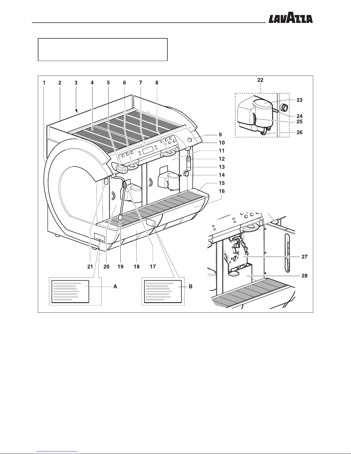
1 - MACHINE COMPOSITION
NOTE - If not expressly indicated in the text, the position numbers of machine parts refer to the following figure.
A Data plate
B System information plate
1 Left hand side panel
2 Glass
3 Rear panel
4 Cup warming plate
5 Steam knob
Clockwise: steam jet open
Counterclockwise: steam jet closed
6 Capsule drawer
7 Control panel
8 Capsule insertion drawer
9 Hot water button
10 Right hand side panel
11 Door
12 Rubber protector
13 Hot water spout
14 Spout clamp
15 Drip tray
16 Capsule drawer
17 Rubber protector
18 Capsule drawer
19 Steam spout
20 Door
21 Main switch
“I” - Enabled electric functions – Machine on –
LED illuminated.
“O” - Disabled electric functions – Machine off –
Button “I” LED turned off.
22 Coffee brew group
23 Brew group cover
24 Milk foam control
25 Temperature adjusting knob
26 Milk dispenser
27 Brew group
28 Capsule discharge hopper
••5
ENGLISH
2 - EXPLANATORY NOTES
2.1 Abbreviations
F. = Figure
P. = Page
Sect. = Section
T. = Table
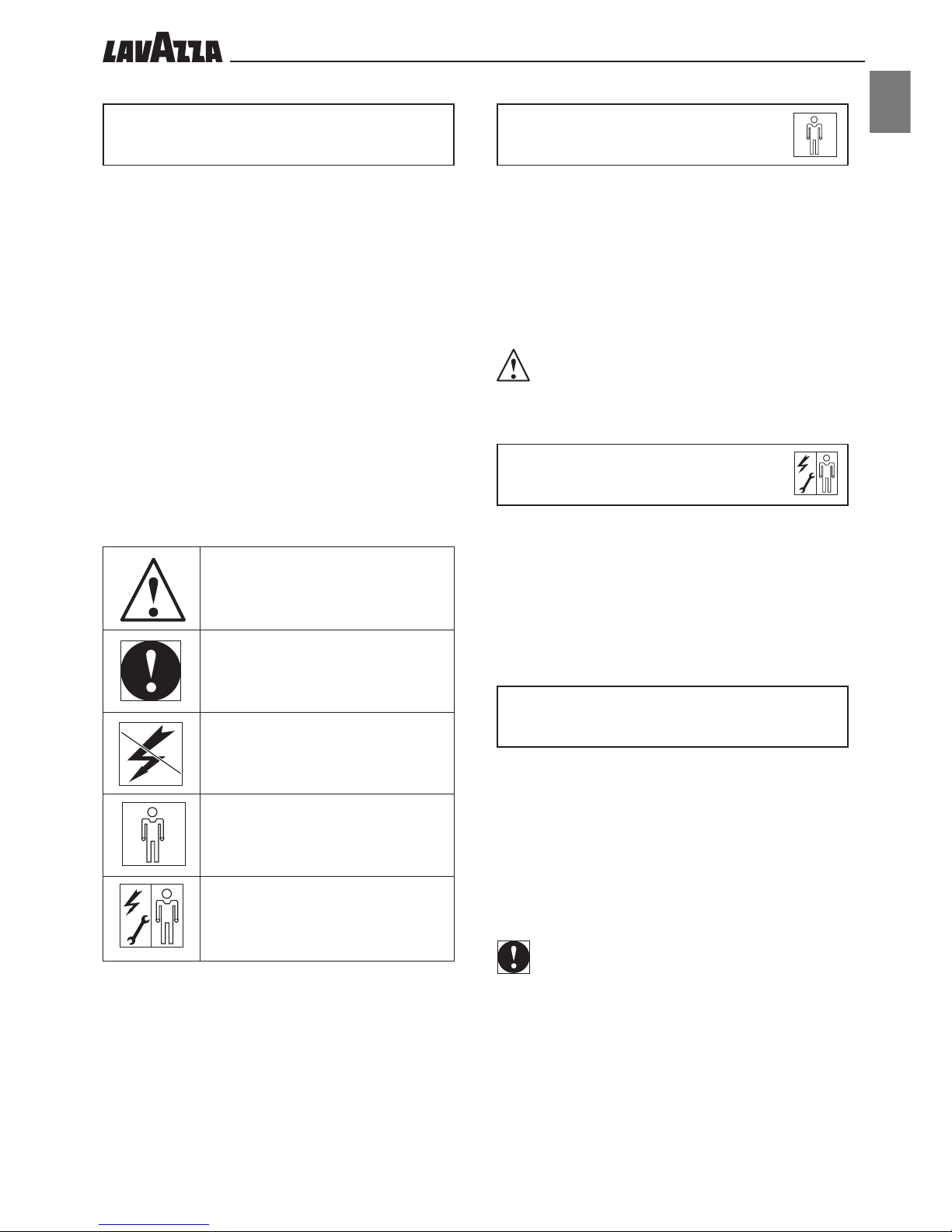
2.2 Editing symbols
WARNING!
Please pay close attention to the symbols: they are not designed
so that technical concepts or safety warnings do not have to be
repeated. They should thus be considered as memory prompts.
Please read the list of symbols whenever in doubt about their
meaning.
WARNING! - Information regarding user safety and machine integrity.
IMPORTANT! - Draws attention to particularly important issues.
Maintenance technician – Operations to
be performed exclusively by personnel in charge of unscheduled maintenance and repairs.
Machine off – Operations to be performed with power supply cut off.
User – Operations to be performed by the
user of the machine.
3 - USER
Adult person who is exclusively in charge of the following operations:
- Use, control and turning off of the machine.
- Brewing parameters setting.
- Emptying the ground and liquid trays.
- External cleaning of the machine.
WARNING
Children, teenagers and people unable to care for
themselves are prohibited from using this machine .
4 - MAINTENANCE
TECHNICIAN
Person in charge of the following operations:
- Installation, start-up, adjustment and setting up of the machine.
- Unscheduled maintenance, repairs and replacement of spare
parts.
5 - INTENDED USE OF THE
MACHINE
The machines in this manual have been designed, manufactured
and protected for automatic dispensing (programmable) of the
following beverages:
- coffee based capsules;
- milk and coffee based capsules.
- hot water and water steam for the preparation and heating of
beverages.
- hot milk.
IMPORTANT
Any other use of the machines is not foreseen by the
Manufacturer who is exempted from any liability for any
damage caused by their improper use. The improper use
also causes any type of warranty to expire.
••6
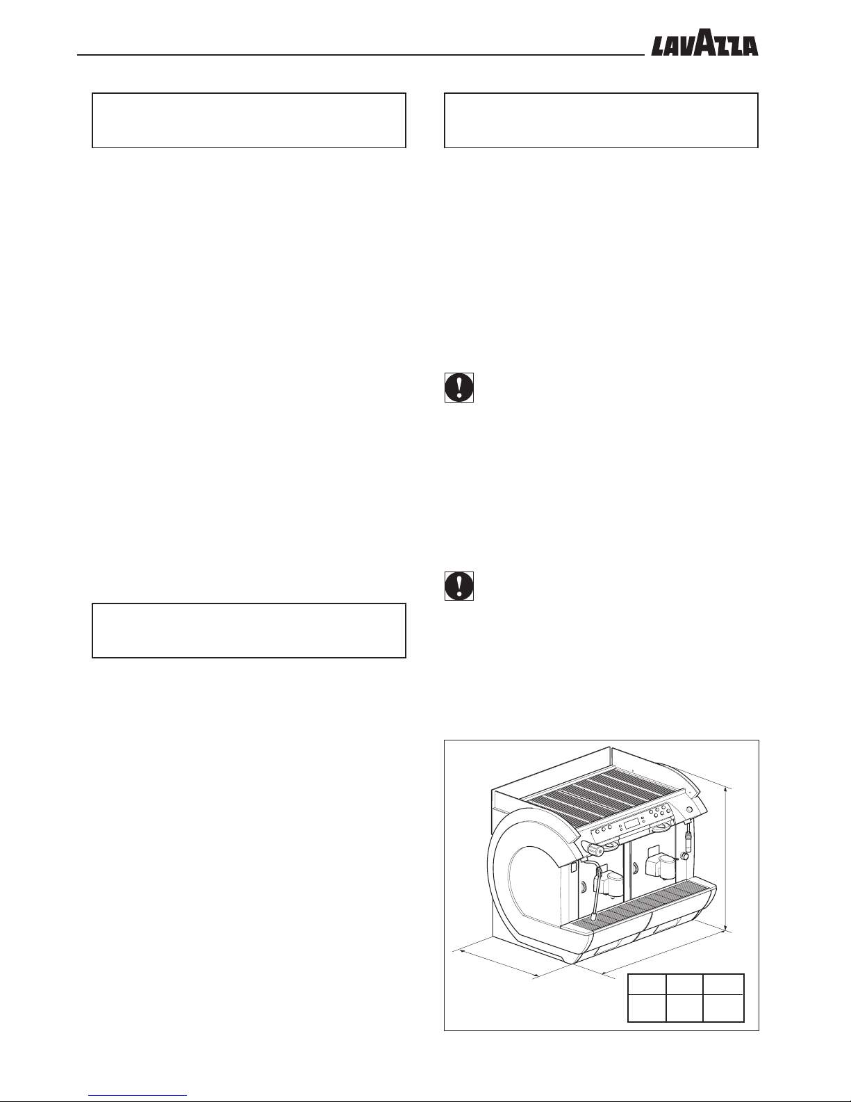
LPh
745 550 625
F. 2
L
P
h
6 - WARNINGS AND
CAUTIONS
Do not use detergents, thinners, solvents etc. for scheduled maintenance.
Cleaning is limited to non-live parts and must be performed by using
neutral or biodegradable products, or with the power cable unplugged.
Scheduled maintenance must be performed by qualified personnel or at least by suitably informed and trained personnel, with the necessary mental and physical requirements, and in full compliance with the
instructions indicated below and with the Safety and Health Regulations
in force.
It is strictly forbidden to place and/or leave tools or anything else
on the machine which may be detrimental to people’s safety or the
integrity of the machine.
Changes and tampering (even slight), as well as the use of non
original spare parts, exempt the Manufacturer from any liability for damages of any kind and cause the warranty to expire.
Use drinking water only.
N.B.: Do not use hot water.
It is essential to supply the machine with water treated by a descaling
device, which guarantees the compliance with the abovementioned
limitations. Make sure the water network provides drinking water, with
pressure ranging between 1 and 8 Bars.
7 - GENERAL PRECAUTIONS
• Before using the appliance, always make sure that the con-
tents of this manual have been thoroughly understood beforehand. Failure to comply with the instructions in this manual
exempts the Manufacturer from any liability for damages of
any kind caused to persons and/or property.
• Keep this edition for future reference.
• If installing for the first time, check beforehand for complian-
ce with the minimal safety regulations, placing and operability
of the machine, by taking note of environmental conditions
(temperature, humidity, light) and the suitability of the working
space.
• Any damage to the power cable requires Authorized Techni-
cal Assistance or a maintenance technician.
• Do not use the machine outdoors.
• In the event of failure, always ask the maintenance techni-
cian for assistance.
• Do not use water jets to clean the machine.
8 - INFORMATION ABOUT
THE MACHINE
8.1 Identification data
Plate (A) displays the following machine identification data:
• Manufacturer and marking
• model
• Serial no.
• year of manufacture
• supply voltage (V) and frequency (Hz)
• power consumption (W)
• number of phases of the electrical power line
• permitted pressure in the water network (MPa)
IMPORTANT
When contacting the Authorized Customer Service Centres,
please indicate model and serial number of the machine.
8.2 Technical features
Power supply voltage .................... 240V 60Hz
Power cable length ....................... mm 1.700
Installed power .......................... 5500 W
Water pressure .........................MPa0.1÷0.8 (1÷8 bar)
Weight ....................................kg 66
IMPORTANT
The machines are programmable for any type of dispensing
dosage. Most of the electrical components are supplied with
24 VDc.
8.3 Overall dimensions
••7
ENGLISH
F. 3
F. 4
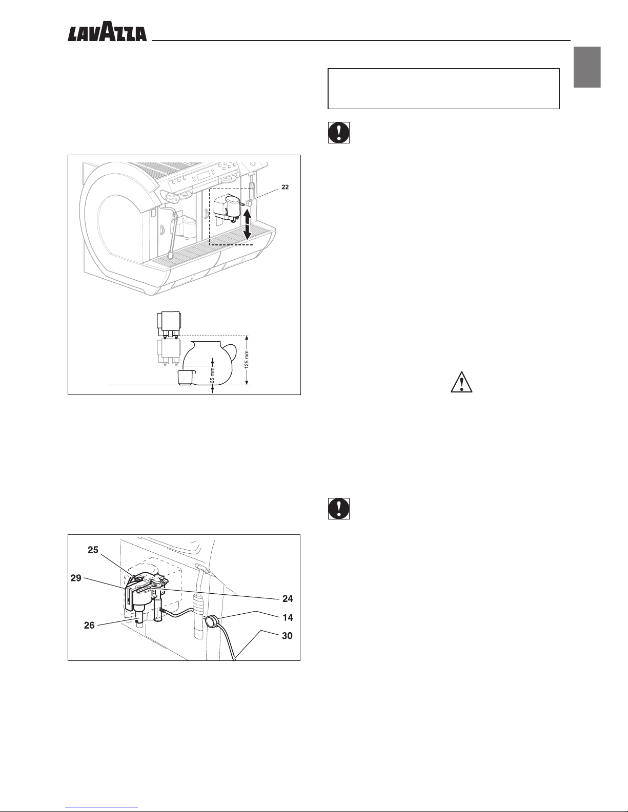
8.4 Brew group
The position of this group (22) can be changed according to the height
of the container used.
It is possible to position the brew group at the top or at the
bottom.
Different brewing heights can therefore be obtained.
8.5 Cappuccinatore Group
The cappuccinatore group is composed of:
- milk suction pipe (30);
- spout clamp (14);
- cappuccinatore (29);
- cream quality control (24);
- temperature setting lever (25);
- Milk dispenser (26).
The milk used for the CAPPUCCINATORE must be kept in a fridge at a
temperature no higher than 4° C; do not leave it outside the fridge for
more than 30 minutes.
9 - SAFETY DEVICES
IMPORTANT
The machines in this manual are manufactured in
compliance with the relevant Directives in force and are
therefore protected as to all parts which may be potentially
dangerous.
Any overpressure of the water system which controls the
production of steam and hot water is detected by 3 safety valves.
A thermostat prevents the boilers from overheating.
The position of the capsule drawer (16 and 18) and of the
door (11 and 20), is controlled by 2 microswitches which stop
the machine if one of the components is not properly in place;
(the display will show the component out of place).
An electronic pulse counter saves the number of beverages
produced and enables planning of the scheduled maintenance.
The steam (19) and hot water (13) spouts are equipped
with suitable rubber protectors (12 and 17) so they can be held
and directed even if hot.
9.1 Residual risks
The manufacturing characteristics of the machines in this publication do not protect the user from steam or hot water jets.
Danger of burns – When dispensing hot water or steam,
do not direct the jets towards other people or yourselves. Only
hold the pipe on the appropriate anti-burning protections (12
and 17).
IMPORTANT
Do not use containers not made of “food-safe” materials.
••8
75 667
296 296
80288183
70
F. 5
A
B
B
B
B
F. 7
G
F
H
I
F. 6
C
D
E
H
10 - INSTALLATION
10.1 Notes on location
The machine must be installed in a dry and sheltered area, with:
- ambient temperature: +10° C + 25° C
- maximum humidity: 65%.
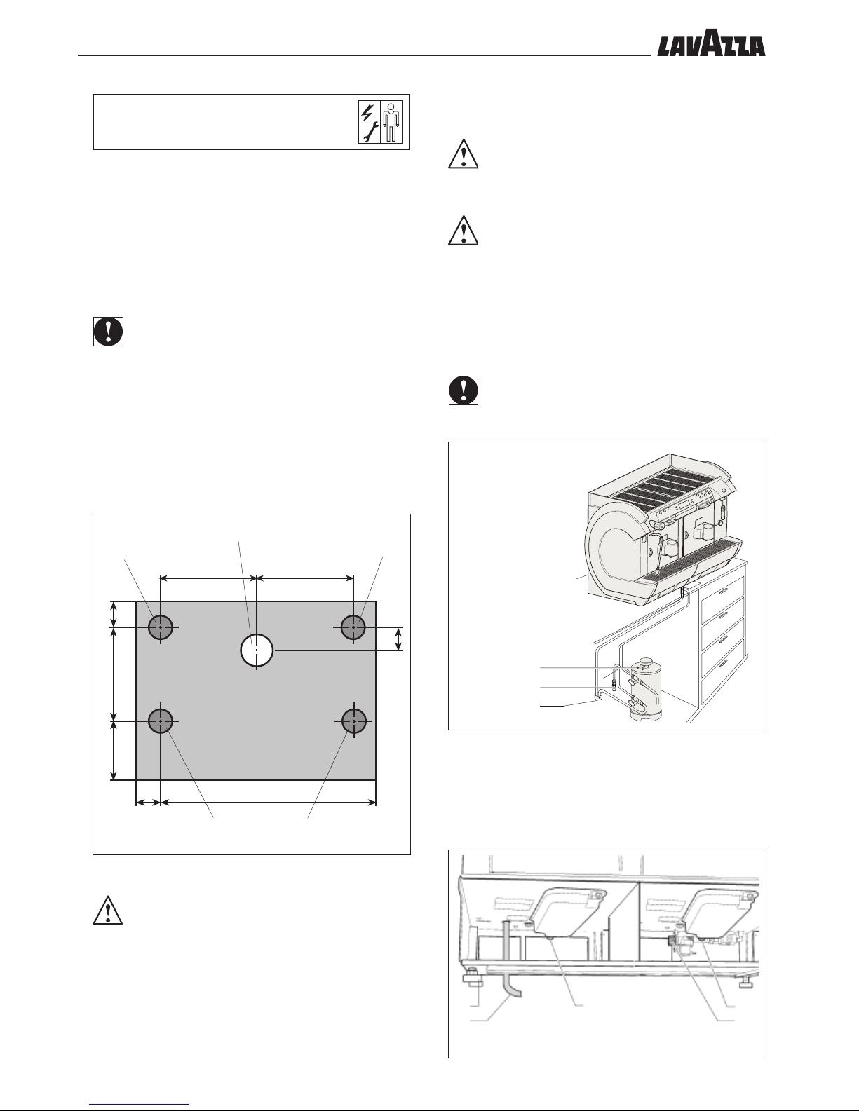
10.2 Machine positioning
IMPORTANT
Check that the installation surface is large and solid enough to
support the machine safely.
Make a Ø 100 mm hole (A - F. 5) on the supporting surface.
Place the machine in a steady position on the supporting surface (the
circles B – F. 5 indicate the optimal position of the adjustable feet).
Level the machine using the adjustable feet (F – F. 7).
10.3 Water connection
WARNING
Water and waste connections shall complhy with applicable
federal states, or local codes.
WARNING
Water hardness should never be above 8°F.
It is essential to supply the machine with water treated by a descaling
device, which guarantees compliance with the abovementioned limitations. Make sure the water network provides drinking water, with pressure ranging between 1 and 8 Bars.
- Connect the purifier (C) to the water network (D).
IMPORTANT
Before connecting the purifier to the machine, perform a washing
cycle until the water is clear; then proceed with the connection
of the purifier to the machine.
C – PURIFIER
D – WATER NETWORK
E - DRAIN CHANNEL
Connect a drain hose to the coupling (H – F. 7) and fasten it using the
hose clamp.
Using only using a hose and couplings made of “food-safe” materials,
connect the machine to the drinking water network, by means of the
coupling (I – F. 7).
Insert the outlet and filling pipes into the hole A.
WARNING /IMPORTANT
For a correct and ergonomic use of the machine, it is
recommended to install it onto a surface which is at least 1 m
high.
••9
ENGLISH
F. 9
L
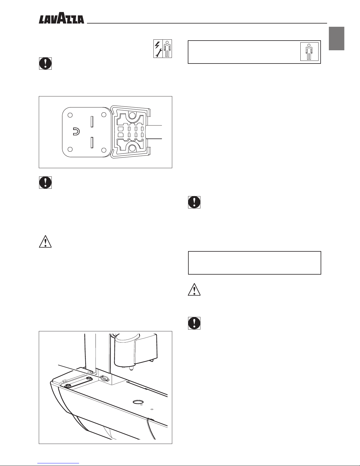
10.4 Electrical connection
IMPORTANT
The machine must be connected to a system-mono phase 240V
60Hz.
Insert the power cable (G – F.7) into hole A (F. 5).
According to the laws in force in the country of use of the machine,
the power cable must be equipped with an all-polar switch (with
minimum distance of 3 mm between contacts).
• The all-polar switch must be suitable to the machine supply
voltage and able to monitor all voltage polarities.
• Check that the size of the cables is suitable for the machine’s
absorption.
The connection point (socket or all-polar switch) must be located
in an easily accessible place for the user to be able to disconnect
the machine from the power supply line, if necessary.
Connect the cable (G - F. 7) to the power supply line.
10.5 Serial port connection
By means of the serial port RS 232 the machine may be connected to a
Personal Computer or devices supplied to the AUTHORIZED CUSTOMER SERVICE CENTRES for programming operations (L - F. 9).
11 - FIRST START-UP
OF THE MACHINE
Check that the removable parts (15,16 and 18) are present and that
the doors (11 and 20) are closed.
Otherwise, the message indicating the part out of place will appear on the display when the machine is turned on.
- Turn on the machine by means of the relevant switch (21);
- Open the capsule insertion box (6 and 8).
- Insert the capsule in the relevant seat as shown in figure F. 11
- Place the dispenser (22) so that a suitable height can be obtai-
ned for the containers used (Pr. 8.4).
- Place a container below the dispenser.
- Press the button corresponding to the type of beverage chosen.
IMPORTANT
Even though all the buttons have been already programmed to
standard values, it is necessary to check that the quantity of the
beverage dispensed corresponds to the one chosen. Otherwise
the dispensing buttons must be programmed (Pr. 12.6)
12 - USE OF THE MACHINE
WARNING
It is important to have read this manual carefully before use, to
ensure sufficient knowledge of the machine.
IMPORTANT
After a long period of disuse, the previous section “First
start-up of the machine” must be read before
the machine is used.
12.1 Machine status
Depending on the power supply, the machine may be in the following
conditions:
Off and electrically insulated
- Main switch (21) set in “0” position (or machine unplugged).
- Only the settings memory is active.
On
- Main switch (21) (or machine plugged).
- All functions are active and the display is on.
F. 8
••10
F. 10
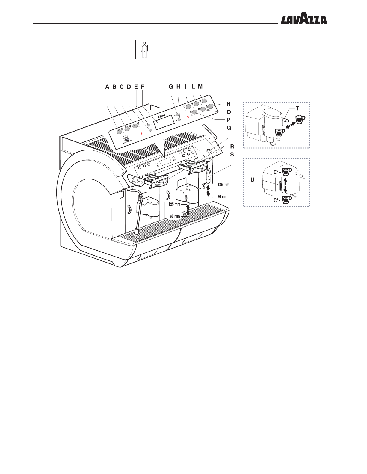
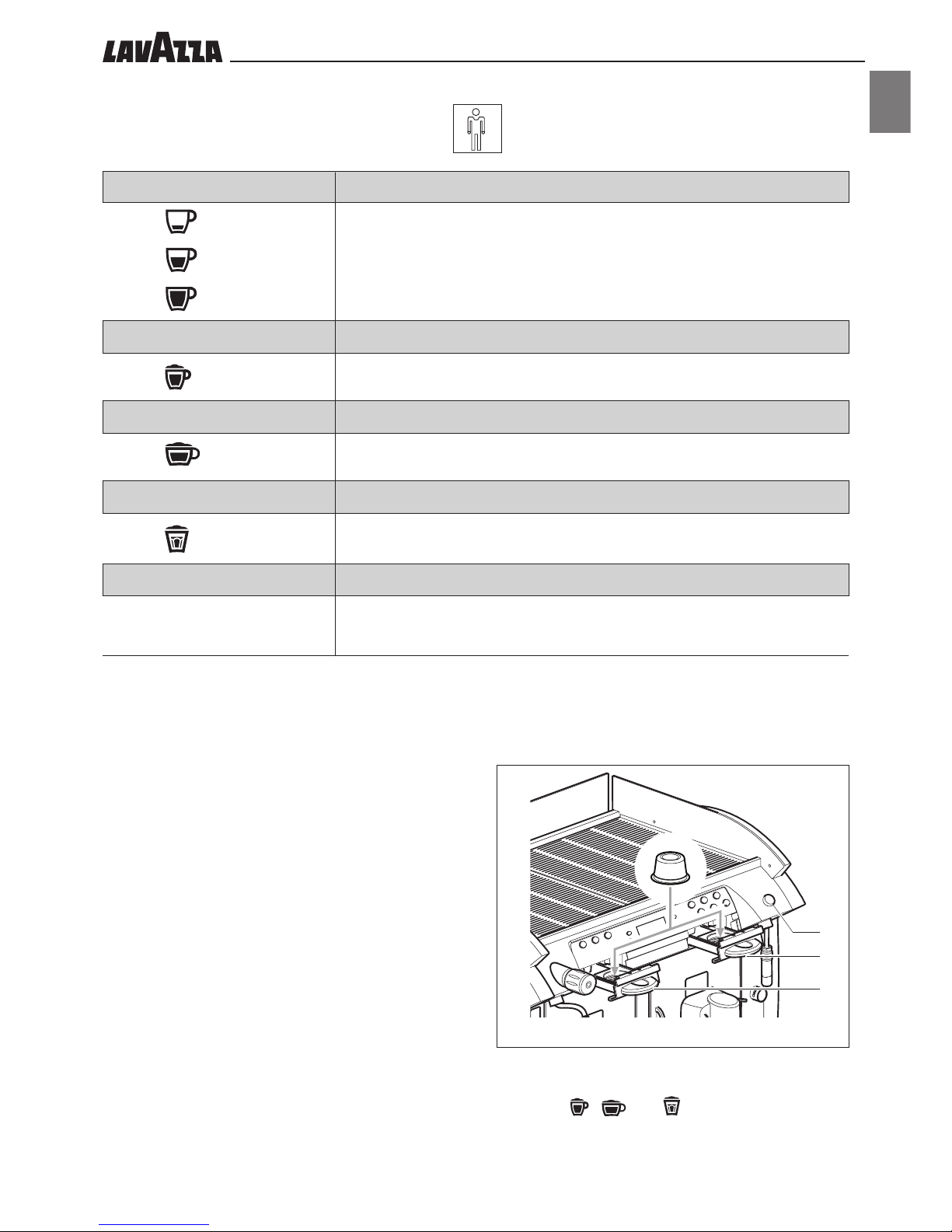
12.2 Control description
A “Strong coffee” key
B “Medium coffee” key
C “Long coffee” key
D “Down” key
E “Up” key
F Display
G “Esc” key
H “Ent” key
I “Strong coffee” key
L “Medium coffee” key
M “Long coffee” key
N “Hot milk” key
O “Cappuccino” key
P “Espresso macchiato” key
Q “Hot water” key
R Capsule insertion drawer
S Hot water spout
T Milk foam control
U Milk temperature adjusting knob
••11
ENGLISH
A , I
B , L
C, M
P
O
N
F. 11
6
8
L
Q
COFFEE
• Definitions: “Strong coffee” – “Medium coffee” – “Long coffee”, indicate three
different dispensing levels.
• On delivery the machines are set to default values.
(**)
ESPRESSO MACCHIATO
• Beverage composed of coffee with a dash of milk.
(*) , (**) , (***)
CAPPUCCINO
• Beverage composed of coffee and hot milk.
(*) , (***) , (***)
HOT MILK
• Beverage composed of milk only
(*) , (***)
HOT WATER
• Dispensing obtained using water
(*)
Milk foam adjustment
The quality of cream in the beverages depends on the use of the
adjustment lever (T).
• By turning the lever to the right, a greater quantity of cream can
be obtained.
• By turning the lever to the left, there will be a smaller quantity of
cream.
Milk temperature setting
The milk temperature is adjusted through the lever (U).
• By turning the lever upward, the temperature will increase.
• By turning the lever downward, the temperature will decrease.
(**)
Inserting the capsules
• Open the capsule box (6 and 8).
• Insert the capsule in the relevant seat as shown in figure F. 11
(***)
NB:.: Keys , and can be preset for brewing
beverages with any possible combination of milk and coffee.
Please refer to an authorized customer service centre to change
the default settings.
strong
medium
long
••12
p1. Products
p1.1. Global................................................ 40
p1.1.1. AutoProgram ........................... 40
p1.1.2. Prebrewing.............................. 40
p1.1.3. Milk Drainage ......................... 40
p1.1.4. Milk Cleaning .......................... 40
p1.2. Details ................................................ 41
p1.2.1. Left products ........................... 41
p1.2.2. Right products ..................... 42-43
p1.2.3. HotWater ............................... 43
p2. System
p2.1. Temperature ........................................ 43
p2.1.1. Delta Temperature .................... 43
p2.1.2. Coffee Heater*
p2.2. Security .............................................. 44
p2.2.1. Operator Password .................. 44
p2.2.2. Technical Password*
p2.3. Options .............................................. 44
p2.3.1. Cup Heater............................. 44
p2.3.2. Antifreezing*
p2.3.3. Unit Visible*
p2.3.4. Buzzer*
p2.4. Date/Time .......................................... 44
p2.4.1. Date ...................................... 44
p2.4.2. Date Format ............................ 44
p2.4.3. Time ....................................... 44
p2.4.4. Time format ............................. 44
p3 Factory Default . ........................................ 44
s1. Maintenance
s1.1. Water filter.......................................... 45
s1.1.1. New filter date ......................... 45
s1.1.2. Liters to Renew ......................... 45
s1.1.3. Filter limit ................................. 45
s1.1.4. Reset filter ................................ 45
s1.1.5. Filter enable ............................. 45
s1.2. Drillers ................................................ 45
s1.2.1. Warning enabled ..................... 45
s1.2.2. Left drillers states ...................... 45
s1.2.3. Right drillers states .................... 45
s1.3. Test mode*
s1.3.1. Master test*
s1.3.2. Left Coffee test*
s1.3.3. Right Coffee test*
s1.3.4. Water/Steam test*
s2. System Info
s2.1. Identification ....................................... 47
s2.1.1. Software Version ...................... 47
s2.1.2. Machine Code ........................ 47
s2.2. Error Log ............................................. 47
s2.2.1. Errors ...................................... 47
s2.2.2. Reset log*
s2.3. Audit.................................................. 48
s2.3.1. Counters from init ..................... 48
s2.3.2. Counters from reset ................... 48
s2.3.3. Reset Audit
.............................. 48
s3. Install/Uninstall
s3.1. Install*
s3.1.1. Language*
s3.1.2. Machine Code*
s3.1.3. Display Contrast*
s3.2. Uninstall*
s3.2.1. Empty Boiler*
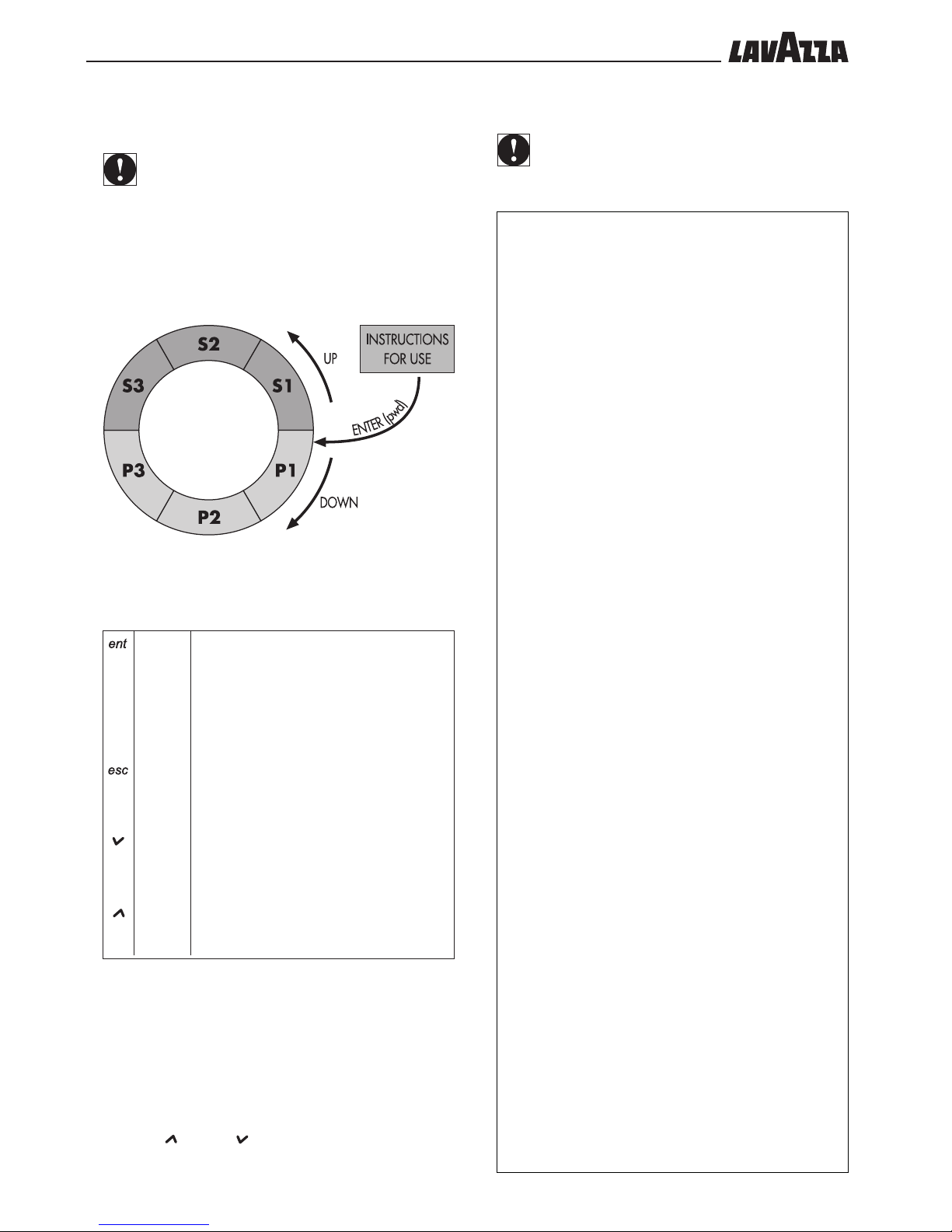
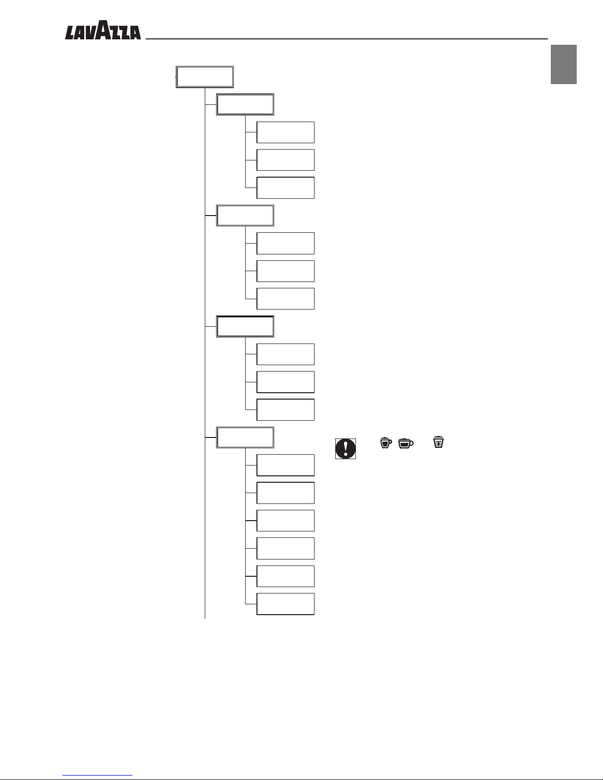
12.3 Menu programmable functions
IMPORTANT
The machine allows some adjustments and settings through
the menu settings, which adapt the dispensed product to
the User requirements
To easily access the programming menu, please see the figure
below:
(Enter) to access the programming menu (the following will
appear on the display: “PASSWORD”);
to move from one menu level to the next; prepare data to be changed; confirm data or a
function;
(Escape) to cancel the changes not confirmed;
to go back up to the previous menu level until
the menu is exited.
(Down) to move to the next item within the same pro-
gramming level;
to increase the value of data to be changed.
(Up) to move to the previous item within the same
programming level;
to reduce the value of data to be changed.
Some functions require the setting of one or more parameters
(already set to standard values).
To operate on data values to be re-set, the following is necessary:
- Select function.
- Confirm function using the “ENT” (Enter) key.
- The flashing cursor appears under the value to be changed.
- Use the “ ” (Up) or “ ”(Down) keys to change its value.
- Confirm changed data using the “ENT” (Enter) key.
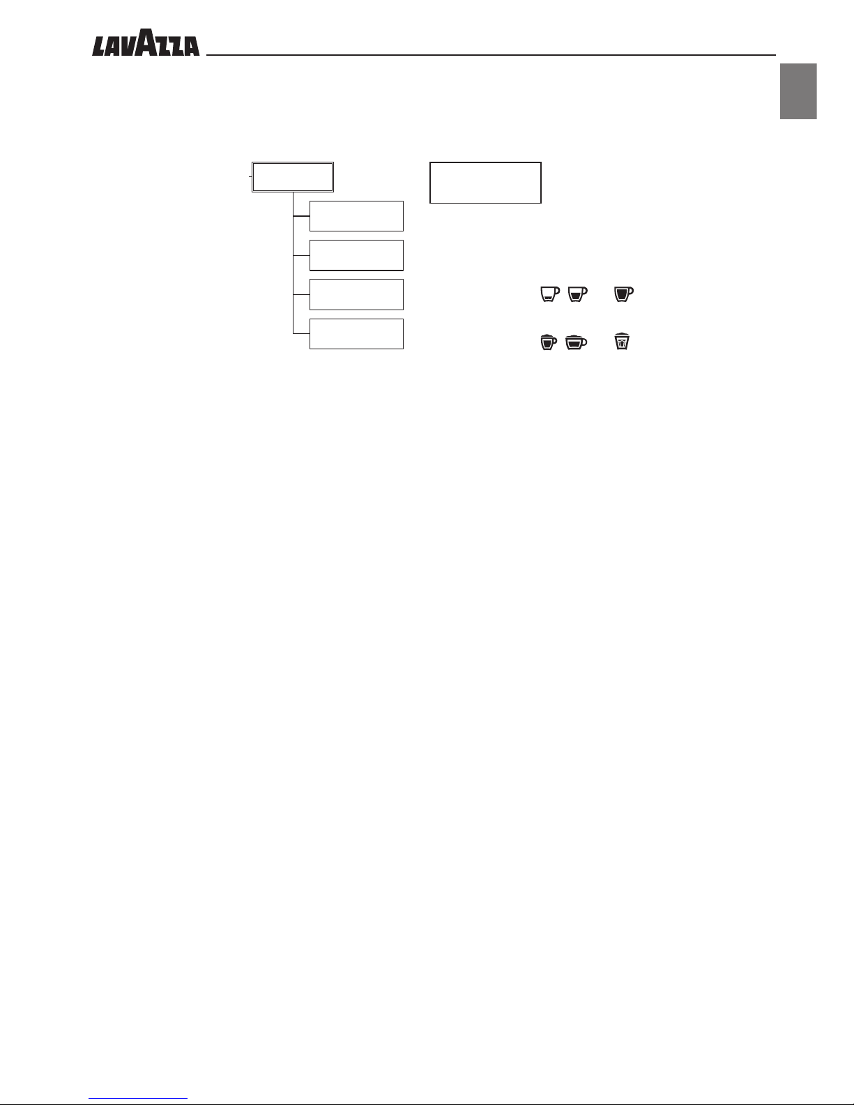
12.4
Structure of the programming menu
IMPORTANT
During programming, the menu items marked with an *
can be viewed (and therefore programmable) only with
the “Technician Password”.
••13
ENGLISH
p1. Products
p1.1. Global
p1.1.1. AutoProgram
p1.1.2. Prebrewing
p1.1.3. Milk Drainage
p1.1.4. Milk Cleaning
p1.2. Details
p1.2.1. Left products
p1.2.2. Right products
p1.2.3. HotWater
p2. System
p2.1. Temperature
p2.1.1. Delta Temperature
p2.1.2. Coffee Heater
p2.2. Security
p2.2.1. Operator Password
p2.2.2. Technical Password
p2.3. Options
p2.3.1. Cup Heater
p2.3.2. Antifreezing
p2.3.3. Unit Visible
p2.3.4. Buzzer
p2.4. Date/Time
p2.4.1. Date
p2.4.2. Date Format
p2.4.3. Time
p2.4.4. Time format
p3. Factory Default
s1. Maintenance
s1.1. Water filter
s1.1.1. New filter date
s1.1.2. Liters to Renew
s1.1.3. Filter limit
s1.1.4. Reset filter
s1.1.5. Filter enable
s1.2. Drillers
s1.2.1. Warning enabled
s1.2.2. Left driller state
s1.2.3. Right driller state
s1.3. Test mode
s1.3.1. Master test
s1.3.2. Left Coffee test
s1.3.3. Right Coffee test
s1.3.4. Water/Steam test
s2. System Info
s2.1. Identification
s2.1.1. Software Version
s2.1.2. Machine Code
s2.2. Error Log
s2.2.1. Errors
s2.2.2. Reset log
s2.3. Audit
s2.3.1. Counters from init
s2.3.2. Counters from reset
s2.3.3. Reset Audit
s3. Install/Uninstall
s3.1. Install
s3.1.1. Language
s3.1.2. Machine Code
s3.1.3. Display Contrast
s3.2. Uninstall
s3.2.1. Empty Boiler
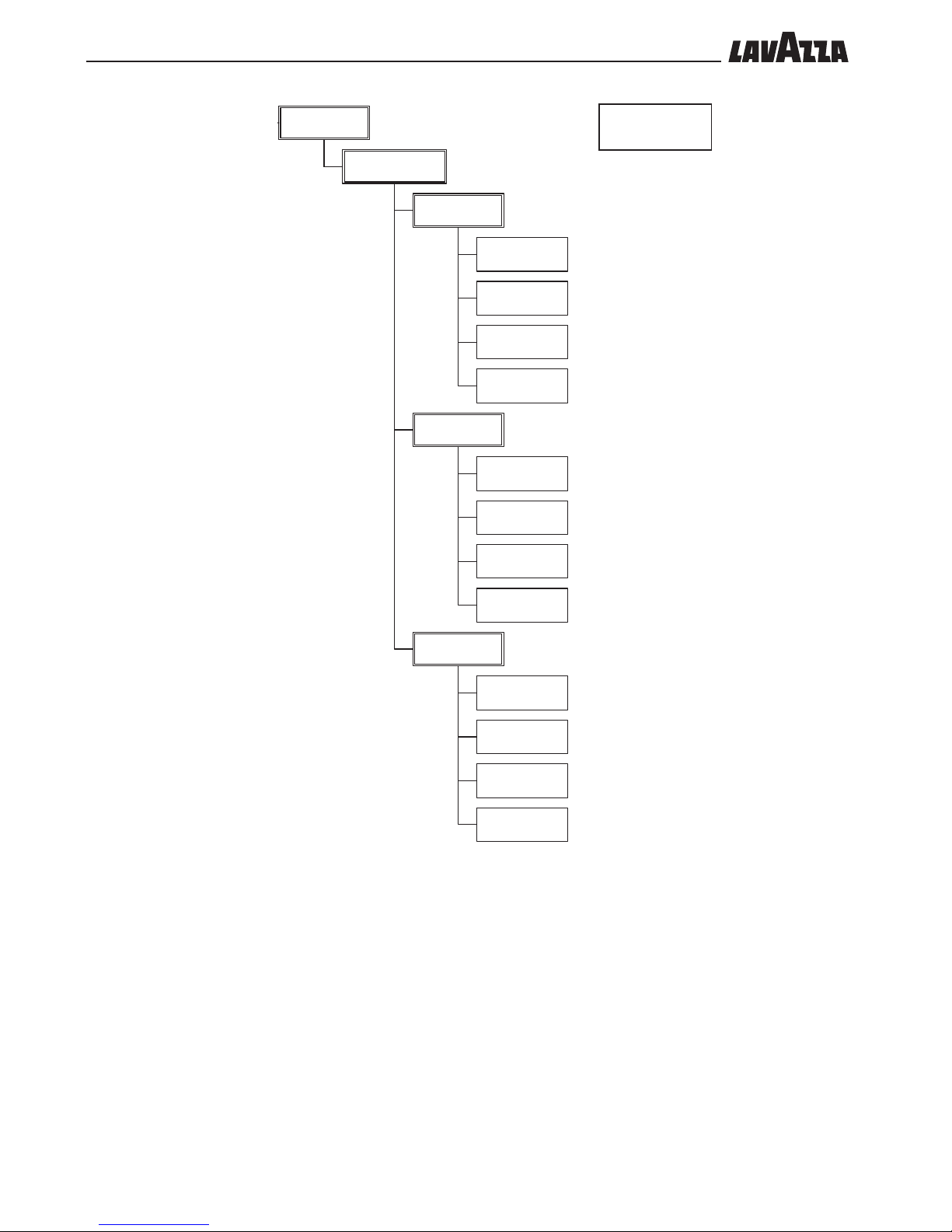
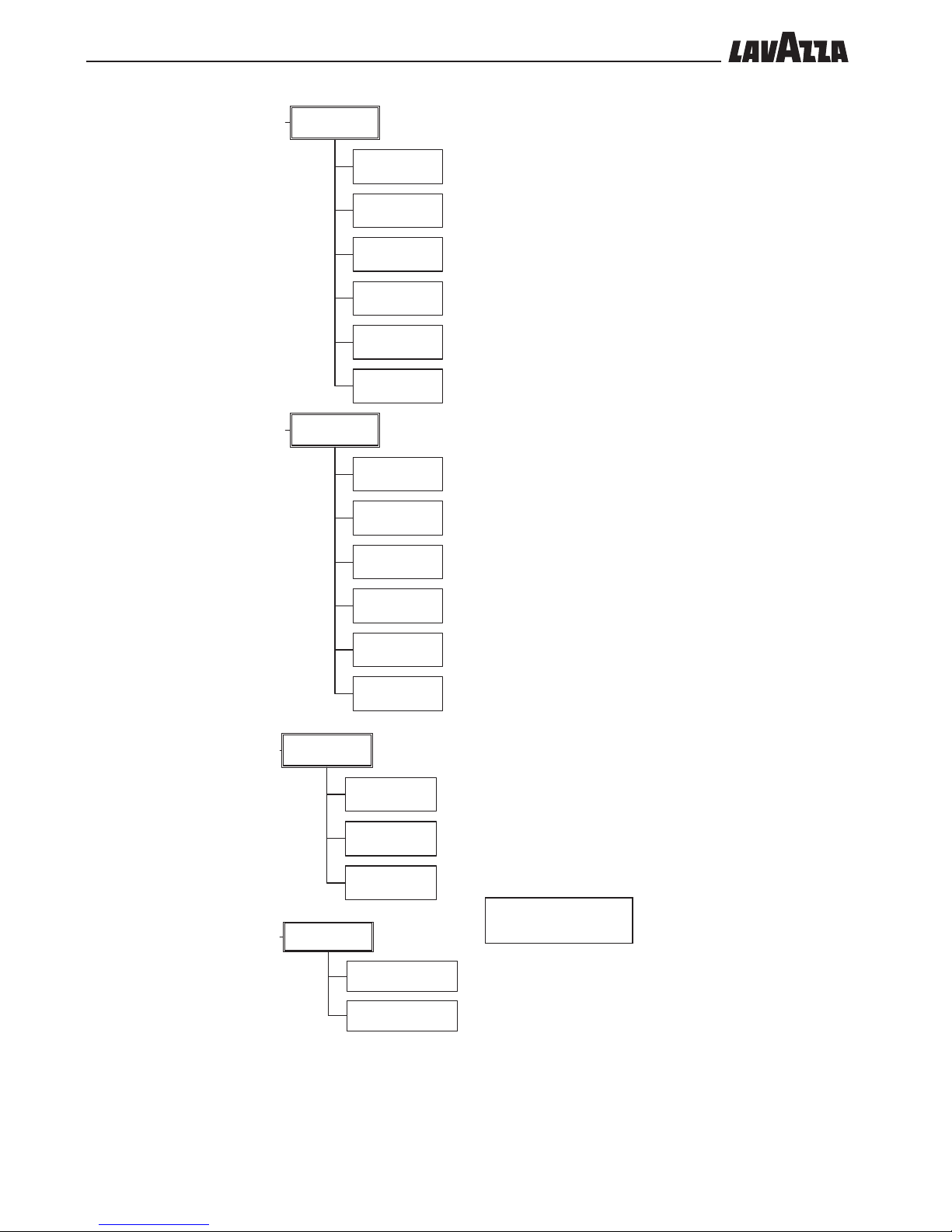
12.5 Function description
P1.1
GLOBAL
P1.1.1 Auto-programming
This functions enables to set the beverage dose.
To set the dose, press the “ENT” key and access the menu item
“P.1.1.1.1 AUTOPROG. RUNNING”:
- to program the keys , and , press the selected key to
start the programming, press the key again to save the desired
dose.
- to program the keys , and , press the selected key to
start the programming of the product, press the key again to save
the desired dose of coffee and press the key again to save the
desired dose of milk.
The saved values will be shown on the display at the end of the
programming.
P1.1.2 Prebrewing
This function enables to stop the first brewing phase for a while. This
may improve the quality of coffee which can “brew” with the first
part of water, during the stop.
The length of the stop can be set with increasing values: 0, +, ++,+++.
P1.1.3 Milk drainage
This function indicates the opening time of the solenoid valve draining the condensate in the pipe which supplies the steam to the
cappuccinatore. It can be adjusted from 0 to 8 seconds.
P1.1.4 Milk cleaning
This function indicates the length of steam washing which is performed at the end of any milk dispensing. It can be adjusted from 0 to
8 seconds.
P1.1.
Global
P1.1.1.
AutoProgram
P1.1.2.
Prebrewing
P1.1.3.
Milk Drainage
P1.1.4.
Milk Cleaning
••14
P1.2.
Details
P1.2.1.
Left products
P1.2.1.1.
Espresso
P1.2.1.1.1.
Test
P1.2.1.1.2.
Multiple
P1.2.1.1.3.
Dose
P1.2.1.1.4.
Copy to all
P1.2.1.2.
Coffee
P1.2.1.2.1.
Test
P1.2.1.2.2.
Multiple
P1.2.1.2.3.
Dose
P1.2.1.2.4.
Copy to all
P1.2.1.3.
Large Coffee
P1.2.1.3.1.
Test
P1.2.1.3.2.
Multiple
P1.2.1.3.3.
Dose
P1.2.1.3.4.
Copy to all
p1. Products
p1.1. Global
p1.1.1. AutoProgram
p1.1.2. Prebrewing
p1.1.3. Milk Drainage
p1.1.4. Milk Cleaning
p1.2. Details
p1.2.1. Left products
p1.2.2. Right products
p1.2.3. HotWater
p2. System
p2.1. Temperature
p2.1.1. Delta Temperature
p2.1.2. Coffee Heater
p2.2. Security
p2.2.1. Operator Password
p2.2.2. Technical Password
p2.3. Options
p2.3.1. Cup Heater
p2.3.2. Antifreezing
p2.3.3. Unit Visible
p2.3.4. Buzzer
p2.4. Date/Time
p2.4.1. Date
p2.4.2. Date Format
p2.4.3. Time
p2.4.4. Time format
p3. Factory Default
s1. Maintenance
s1.1. Water filter
s1.1.1. New filter date
s1.1.2. Liters to Renew
s1.1.3. Filter limit
s1.1.4. Reset filter
s1.1.5. Filter enable
s1.2. Drillers
s1.2.1. Warning enabled
s1.2.2. Left driller state
s1.2.3. Right driller state
s1.3. Test mode
s1.3.1. Master test
s1.3.2. Left Coffee test
s1.3.3. Right Coffee test
s1.3.4. Water/Steam test
s2. System Info
s2.1. Identification
s2.1.1. Software Version
s2.1.2. Machine Code
s2.2. Error Log
s2.2.1. Errors
s2.2.2. Reset log
s2.3. Audit
s2.3.1. Counters from init
s2.3.2. Counters from reset
s2.3.3. Reset Audit
s3. Install/Uninstall
s3.1. Install
s3.1.1. Language
s3.1.2. Machine Code
s3.1.3. Display Contrast
s3.2. Uninstall
s3.2.1. Empty Boiler
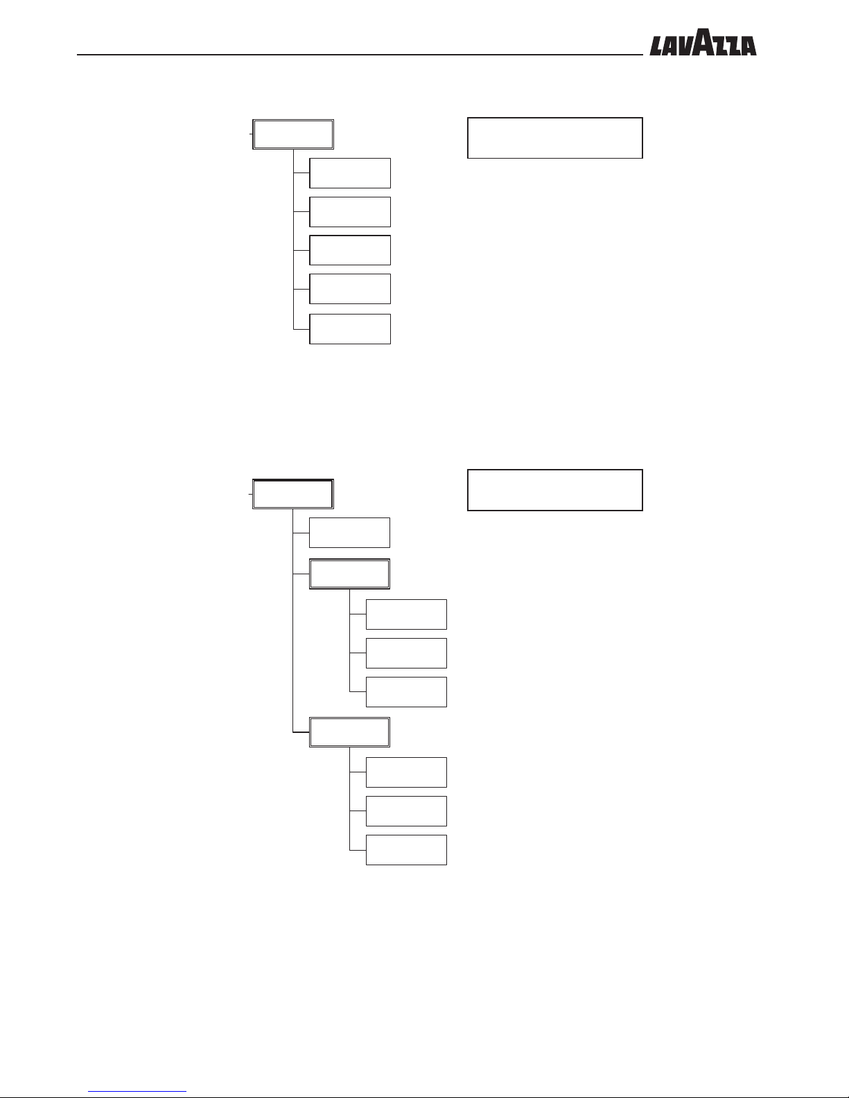
P1.2
DETAILS
P1.2.1 Left products
Enables setting of the parameters of the beverages on the left part of the machine:
P1.2.1.1. Espresso
The full product is displayed and by pressing Enter the following parameters may be
selected/set:
Test: enables dispensing of the product.
Multiple: allows enabling or disabling of
the double dose.
Dose: enables setting of the quantity of water
for the beverage.
Copy to all: enables automatic setting of
the ESPRESSO of the right part of the machine as well as the one on the left part.
P1.2.1.2. Coffee
The full product is displayed and by pressing Enter the following parameters may be
selected/set:
Test: enables dispensing of the product.
Multiple: allows enabling or disabling of
the double dose.
Dose: enables setting of the quantity of water
for the beverage.
Copy to all: enables automatic setting of
COFFEE on the right part of the machine as
well as on the left part.
P1.2.1.3. LargeCoffee
The full product is displayed and by pressing Enter the following parameters may be
selected/set:
Test: enables dispensing of the product.
Multiple: allows enabling or disabling of
the double dose.
Dose: enables setting of the quantity of water
for the beverage.
Copy to all: enables automatic setting of
the LARGECOFFEE on the right part of the
machine as well as on the left part.
••15
ENGLISH
P1.2.2.
Right products
P1.2.2.1.
Espresso
P1.2.2.1.1.
Test
P1.2.2.1.2.
Multiple
P1.2.2.1.3.
Dose
P1.2.2.2.
Coffee
P1.2.2.2.1.
Test
P1.2.2.2.2.
Multiple
P1.2.2.2.3.
Dose
P1.2.2.3.
Large Coffee
P1.2.2.3.1.
Test
P1.2.2.3.2.
Multiple
P1.2.2.3.3.
Dose
P1.2.2.4.
Macchiato
P1.2.2.4.1.
Test
P1.2.2.4.2.
Multiple
P1.2.2.4.3.
Type1
P1.2.2.4.4.
Dose1
P1.2.2.4.5.
Type2
P1.2.2.4.6.
Dose2
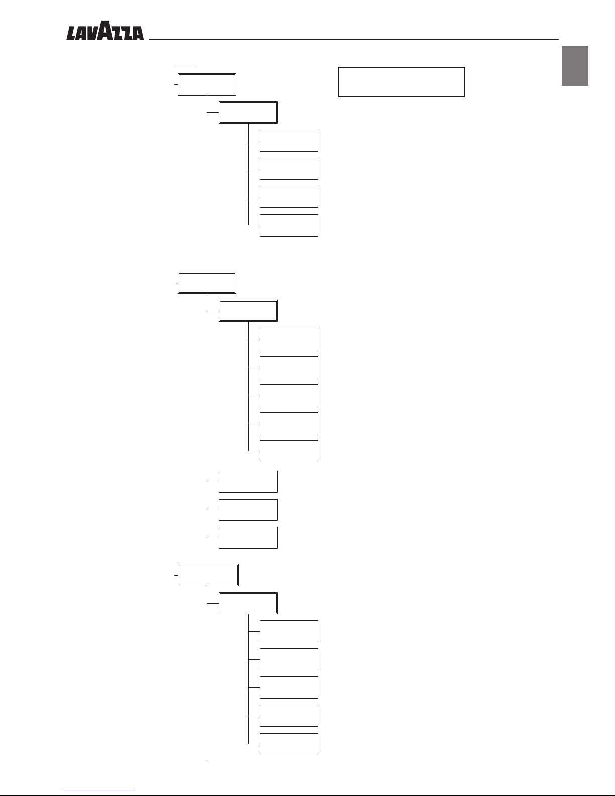
P1.2.2 Right products
Enables setting of the parameters of the beverage on the right part
of the machine:
P1.2.2.1. Espresso
The full product is displayed and by pressing Enter the
following parameters may be selected/set:
Test: enables dispensing of the product.
Multiple: allows enabling or disabling of the double
dose.
Dose: enables setting of the quantity of water for the
beverage.
P1.2.2.2. Coffee
The full product is displayed and by pressing Enter the
following parameters may be selected/set:
Test: enables dispensing of the product.
Multiple: allows enabling or disabling of the double
dose.
Dose: enables setting of the quantity of water for the
beverage.
P1.2.2.3. LargeCoffee
The full product is displayed and by pressing Enter the
following parameters may be selected/set:
Test: enables dispensing of the product.
Multiple: allows enabling or disabling of the double
dose.
Dose: enables setting of the quantity of water for the
beverage.
Keys , and can be preset for brewing
beverages of any possible combination of milk and
coffee.
P1.2.2.4. Macchiato
The full product is displayed and by pressing Enter the
following parameters may be selected/set:
Test: enables dispensing of the product.
Multiple: allows enabling or disabling of the double
dose.
Type1: enables setting of product 1 (COFFEE).
Dose1: enables setting of the quantity of water for beve-
rage 1.
Type2: enables setting of product 2 (MILK).
Dose2: enables setting of the brewing time of product 2.
p1. Products
p1.1. Global
p1.1.1. AutoProgram
p1.1.2. Prebrewing
p1.1.3. Milk Drainage
p1.1.4. Milk Cleaning
p1.2. Details
p1.2.1. Left products
p1.2.2. Right products
p1.2.3. HotWater
p2. System
p2.1. Temperature
p2.1.1. Delta Temperature
p2.1.2. Coffee Heater
p2.2. Security
p2.2.1. Operator Password
p2.2.2. Technical Password
p2.3. Options
p2.3.1. Cup Heater
p2.3.2. Antifreezing
p2.3.3. Unit Visible
p2.3.4. Buzzer
p2.4. Date/Time
p2.4.1. Date
p2.4.2. Date Format
p2.4.3. Time
p2.4.4. Time format
p3. Factory Default
s1. Maintenance
s1.1. Water filter
s1.1.1. New filter date
s1.1.2. Liters to Renew
s1.1.3. Filter limit
s1.1.4. Reset filter
s1.1.5. Filter enable
s1.2. Drillers
s1.2.1. Warning enabled
s1.2.2. Left driller state
s1.2.3. Right driller state
s1.3. Test mode
s1.3.1. Master test
s1.3.2. Left Coffee test
s1.3.3. Right Coffee test
s1.3.4. Water/Steam test
s2. System Info
s2.1. Identification
s2.1.1. Software Version
s2.1.2. Machine Code
s2.2. Error Log
s2.2.1. Errors
s2.2.2. Reset log
s2.3. Audit
s2.3.1. Counters from init
s2.3.2. Counters from reset
s2.3.3. Reset Audit
s3. Install/Uninstall
s3.1. Install
s3.1.1. Language
s3.1.2. Machine Code
s3.1.3. Display Contrast
s3.2. Uninstall
s3.2.1. Empty Boiler
••16
P1.2.2.5.
Cappuccino
P1.2.2.5.1.
Test
P1.2.2.5.2.
Multiple
P1.2.2.5.3.
Type1
P1.2.2.5.4.
Dose1
P1.2.2.5.5.
Type2
P1.2.2.5.6.
Dose2
P1.2.2.6.
Milk
P1.2.2.6.1.
Test
P1.2.2.6.2.
Multiple
P1.2.2.6.3.
Type1
P1.2.2.6.4.
Dose1
P1.2.2.6.5.
Type2
P1.2.2.6.6.
Dose2
P2.1.
Temperature
P2.1.1.
Delta Temperature
P2.1.2.
Coffee Heater
P1.2.3.
Hot Water
P1.2.3.1.
Test
P1.2.3.2.
Multiple
P1.2.3.3.
Manual Dose
P1.2.2.5. Cappuccino
The full product is displayed and by pressing Enter the following
parameters may be selected/set:
Test: enables dispensing of the product.
Multiple: allows enabling or disabling of the double dose.
Type1: enables setting of product 1 (MILK).
Dose1: enables setting of the brewing time of product 1.
Type2: enables setting of product 2 (COFFEE).
Dose2: enables setting of the quantity of water for beverage 2.
P1.2.2.6. Milk
The full product is displayed and by pressing Enter the following
parameters may be selected/set:
Test: enables dispensing of the product.
Multiple: allows enabling or disabling of the double dose.
Type1: enables setting of product 1 (MILK).
Dose1: enables setting of the brewing time of product 1.
Type2: Dose2: -
P1.2.3 Hot water
Enables setting of the parameters for hot water. The following parameters can be selected/set:
Test: enables hot water dispensing.
Multiple: allows enabling or disabling of the function to dispense
up to eight beverages. Function not implemented.
ManualDose: enables setting of the quantity of water to be di-
spensed for each selection.
P2.1
TEMPERATURE
For each coffee dispensed, it is possible to change the temperature
of the water used during dispensing and programmed during the
installation phase.
P2.1.1. Delta Temperature
sets the temperature change for both groups; the setup is the temperature set and the change can be made by means of “+” and “-”
keys:
- by pressing “+” this temperature is increased.
- by pressing “-” this temperature is decreased.
P2.1.2. Coffee Heater (technician only)
p1. Products
p1.1. Global
p1.1.1. AutoProgram
p1.1.2. Prebrewing
p1.1.3. Milk Drainage
p1.1.4. Milk Cleaning
p1.2. Details
p1.2.1. Left products
p1.2.2. Right products
p1.2.3. HotWater
p2. System
p2.1. Temperature
p2.1.1. Delta Temperature
p2.1.2. Coffee Heater
p2.2. Security
p2.2.1. Operator Password
p2.2.2. Technical Password
p2.3. Options
p2.3.1. Cup Heater
p2.3.2. Antifreezing
p2.3.3. Unit Visible
p2.3.4. Buzzer
p2.4. Date/Time
p2.4.1. Date
p2.4.2. Date Format
p2.4.3. Time
p2.4.4. Time format
p3. Factory Default
s1. Maintenance
s1.1. Water filter
s1.1.1. New filter date
s1.1.2. Liters to Renew
s1.1.3. Filter limit
s1.1.4. Reset filter
s1.1.5. Filter enable
s1.2. Drillers
s1.2.1. Warning enabled
s1.2.2. Left driller state
s1.2.3. Right driller state
s1.3. Test mode
s1.3.1. Master test
s1.3.2. Left Coffee test
s1.3.3. Right Coffee test
s1.3.4. Water/Steam test
s2. System Info
s2.1. Identification
s2.1.1. Software Version
s2.1.2. Machine Code
s2.2. Error Log
s2.2.1. Errors
s2.2.2. Reset log
s2.3. Audit
s2.3.1. Counters from init
s2.3.2. Counters from reset
s2.3.3. Reset Audit
s3. Install/Uninstall
s3.1. Install
s3.1.1. Language
s3.1.2. Machine Code
s3.1.3. Display Contrast
s3.2. Uninstall
s3.2.1. Empty Boiler

••17
ENGLISH
P2.2.
Security
P2.2.1.
Operator Password
P2.2.2.
Technical Password
P2.3.
Options
P2.3.1.
Cup Heater
P2.3.2.
Antifreezing
P2.3.3.
Unit Visible
P2.3.4.
Buzzer
P2.4.
Date/Time
P2.4.1.
Date
P2.4.1.1.
Day
P2.4.1.2.
Month
P2.4.1.3.
Year
P2.4.2.
Date Format
P2.4.3.
Time
P2.4.4.
Time format
P2.2
SECURITY
This function enables a password to be assigned to access the
programming. If no password has been assigned, the programming menu is entered directly.
P2.2.1. Operator password
By setting this password, the machine user is not authorized to operate on certain items. (see sect. “12.4
Structure of the programming menu”)
P2.2.2.
Technician password (technician only)
P2.3
OPTIONS
Allows enabling of certain standard functions.
P2.3.1. Cup Heater
By confirming “ON” the cup warming plate turns on together with
the machine.
By confirming “OFF” the cup warming plate is always off.
P2.3.2. Anti-freezing (technician only)
P2.3.3. Unit Visible (technician only)
P2.3.4. Buzzer (technician only)
P2.4
DATE/TIME
This function enables setting of the calendar and the clock of the
machine.
P2.4.1. Date
P2.4.1.1. Day
Allows the date to be changed
P2.4.1.2. Month
Allows the month to be changed
P2.4.1.3. Year
Allows the year to be changed
P2.4.2. Data format
Allows the data format to be changed.
P2.4.3. Time
Enables the time to be changed.
P2.4.4. Time format
Allows the time format to be changed.
p1. Products
p1.1. Global
p1.1.1. AutoProgram
p1.1.2. Prebrewing
p1.1.3. Milk Drainage
p1.1.4. Milk Cleaning
p1.2. Details
p1.2.1. Left products
p1.2.2. Right products
p1.2.3. HotWater
p2. System
p2.1. Temperature
p2.1.1. Delta Temperature
p2.1.2. Coffee Heater
p2.2. Security
p2.2.1. Operator Password
p2.2.2. Technical Password
p2.3. Options
p2.3.1. Cup Heater
p2.3.2. Antifreezing
p2.3.3. Unit Visible
p2.3.4. Buzzer
p2.4. Date/Time
p2.4.1. Date
p2.4.2. Date Format
p2.4.3. Time
p2.4.4. Time format
p3. Factory Default
s1. Maintenance
s1.1. Water filter
s1.1.1. New filter date
s1.1.2. Liters to Renew
s1.1.3. Filter limit
s1.1.4. Reset filter
s1.1.5. Filter enable
s1.2. Drillers
s1.2.1. Warning enabled
s1.2.2. Left driller state
s1.2.3. Right driller state
s1.3. Test mode
s1.3.1. Master test
s1.3.2. Left Coffee test
s1.3.3. Right Coffee test
s1.3.4. Water/Steam test
s2. System Info
s2.1. Identification
s2.1.1. Software Version
s2.1.2. Machine Code
s2.2. Error Log
s2.2.1. Errors
s2.2.2. Reset log
s2.3. Audit
s2.3.1. Counters from init
s2.3.2. Counters from reset
s2.3.3. Reset Audit
s3. Install/Uninstall
s3.1. Install
s3.1.1. Language
s3.1.2. Machine Code
s3.1.3. Display Contrast
s3.2. Uninstall
s3.2.1. Empty Boiler
P3.
Factory default
P3.
FACTORY DEFAULT
(technician only)
••18
S1.1.
Water filter
S1.1.1.
New filter date
S1.1.2.
Liters to Renew
S1.1.3.
Filter limit
S1.1.4.
Reset filter
S1.1.5.
Filter enable
12.6 Structure of the maintenance menu
S1.1.
WATER FILTER
S1.1.1. New filter date
Displays the date of the last descaling.
S1.1.2. Liters to Renew
Displays the litres left before descaling needs to be performed.
S1.1.3. Filter limit
Enables setting the filter duration litres. Press Enter to set the number
of litres.
S1.1.4. Reset filter
Enables performance of the descaling procedure.
S1.1.5. Filter enable
Function which allows enabling/disabling display of the service
warning.
p1. Products
p1.1. Global
p1.1.1. AutoProgram
p1.1.2. Prebrewing
p1.1.3. Milk Drainage
p1.1.4. Milk Cleaning
p1.2. Details
p1.2.1. Left products
p1.2.2. Right products
p1.2.3. HotWater
p2. System
p2.1. Temperature
p2.1.1. Delta Temperature
p2.1.2. Coffee Heater
p2.2. Security
p2.2.1. Operator Password
p2.2.2. Technical Password
p2.3. Options
p2.3.1. Cup Heater
p2.3.2. Antifreezing
p2.3.3. Unit Visible
p2.3.4. Buzzer
p2.4. Date/Time
p2.4.1. Date
p2.4.2. Date Format
p2.4.3. Time
p2.4.4. Time format
p3. Factory Default
s1. Maintenance
s1.1. Water filter
s1.1.1. New filter date
s1.1.2. Liters to Renew
s1.1.3. Filter limit
s1.1.4. Reset filter
s1.1.5. Filter enable
s1.2. Drillers
s1.2.1. Warning enabled
s1.2.2. Left driller state
s1.2.3. Right driller state
s1.3. Test mode
s1.3.1. Master test
s1.3.2. Left Coffee test
s1.3.3. Right Coffee test
s1.3.4. Water/Steam test
s2. System Info
s2.1. Identification
s2.1.1. Software Version
s2.1.2. Machine Code
s2.2. Error Log
s2.2.1. Errors
s2.2.2. Reset log
s2.3. Audit
s2.3.1. Counters from init
s2.3.2. Counters from reset
s2.3.3. Reset Audit
s3. Install/Uninstall
s3.1. Install
s3.1.1. Language
s3.1.2. Machine Code
s3.1.3. Display Contrast
s3.2. Uninstall
s3.2.1. Empty Boiler
S1.2.
DRILLERS
S1.2.1. Warning enabled
Function which allows enabling/disabling the warning to replace
the piercers.
S1.2.2. Left driller state
S1.2.2.1. Last changed
Displays the last replacement of the piercers.
S1.2.2.2. Remaining autonomy
Displays the remaining duration of the piercers.
S1.2.2.3. Change now (technician only)
S1.2.3. Right driller state
S1.2.3.1. Last changed
Displays the last replacement of the piercers.
S1.2.3.2. Remaining autonomy
Displays the remaining duration of the piercers.
S1.2.3.3. Change now (technician only)
S1.2.2.
Left driller state
S1.2.2.1.
Last changed
S1.2.2.2.
Remaining autonomy
S1.2.2.3.
Change now
S1.2.
Drillers
S1.2.1.
Warning enabled
S1.2.3.
Right driller state
S1.2.3.1.
Last changed
S1.2.3.2.
Remaining autonomy
S1.2.3.3.
Change now
••19
ENGLISH
p1. Products
p1.1. Global
p1.1.1. AutoProgram
p1.1.2. Prebrewing
p1.1.3. Milk Drainage
p1.1.4. Milk Cleaning
p1.2. Details
p1.2.1. Left products
p1.2.2. Right products
p1.2.3. HotWater
p2. System
p2.1. Temperature
p2.1.1. Delta Temperature
p2.1.2. Coffee Heater
p2.2. Security
p2.2.1. Operator Password
p2.2.2. Technical Password
p2.3. Options
p2.3.1. Cup Heater
p2.3.2. Antifreezing
p2.3.3. Unit Visible
p2.3.4. Buzzer
p2.4. Date/Time
p2.4.1. Date
p2.4.2. Date Format
p2.4.3. Time
p2.4.4. Time format
p3. Factory Default
s1. Maintenance
s1.1. Water filter
s1.1.1. New filter date
s1.1.2. Liters to Renew
s1.1.3. Filter limit
s1.1.4. Reset filter
s1.1.5. Filter enable
s1.2. Drillers
s1.2.1. Warning enabled
s1.2.2. Left driller state
s1.2.3. Right driller state
s1.3. Test mode
s1.3.1. Master test
s1.3.2. Left Coffee test
s1.3.3. Right Coffee test
s1.3.4. Water/Steam test
s2. System Info
s2.1. Identification
s2.1.1. Software Version
s2.1.2. Machine Code
s2.2. Error Log
s2.2.1. Errors
s2.2.2. Reset log
s2.3. Audit
s2.3.1. Counters from init
s2.3.2. Counters from reset
s2.3.3. Reset Audit
s3. Install/Uninstall
s3.1. Install
s3.1.1. Language
s3.1.2. Machine Code
s3.1.3. Display Contrast
s3.2. Uninstall
s3.2.1. Empty Boiler
S1.3.
TEST MODE
S1.3.1. Master test (technician only)
S1.3.1.1. Low level test (technician only)
S1.3.1.1.1. Keyboards test (technician only)
S1.3.1.1.2. Safety test (technician only)
S1.3.1.1.3. Outputs test (technician only)
S1.3.1.1.4.
Board temperature (technician only)
S1.3.1.
Master test
S1.3.1.1.
Low level test
S1.3.1.1.1.
Keyboard test
S1.3.1.1.2.
Safety test
S1.3.1.1.3.
Outputs test
S1.3.1.1.4.
Board Temperature
S1.3.2.
Left coffee test
S1.3.2.1.
Low level test
S1.3.2.1.1.
Pod drawer test
S1.3.2.1.2.
Heater test
S1.3.2.1.3.
Brewing test
S1.3.2.1.4.
Hydraulic test
S1.3.2.2.
Check motor
S1.3.2.3.
Check flow
S1.3.2.4.
Check temp
S1.3.2.1.5.
Board Temperature
S1.3.3.
Right coffee test
S1.3.3.1.
Low level test
S1.3.3.1.1.
Pod drawer test
S1.3.3.1.2.
Heater test
S1.3.3.1.3.
Brewing test
S1.3.3.1.4.
Hydraulic test
S1.3.3.1.5.
Board Temperature
S1.3.2. Left coffee test (technician only)
S1.3.2.1. Low level test (technician only)
S1.3.2.1.1.
Pod drawer test (technician only)
S1.3.2.1.2. Heater test (technician only)
S1.3.2.1.3. Brewing test (technician only)
S1.3.2.1.4. Hydraulic test (technician only)
S1.3.2.1.5.
Board temperature (technician only)
S1.3.2.2. Check motor (technician only)
S1.3.2.3. Check flow (technician only)
S1.3.2.4. Check temp (technician only)
S1.3.3. Right coffee test (technician only)
S1.3.3.1. Low level test (technician only)
S1.3.3.1.1. Pod drawer test (technician only)
S1.3.3.1.2. Heater test (technician only)
S1.3.3.1.3. Brewing test (technician only)
S1.3.3.1.4. Hydraulic test (technician only)
S1.3.3.1.5. Board temperature (technician only)
••20
S1.3.3.2. Check motor (technician only)
.
S1.3.3.3. Check flow (technician only)
S1.3.3.4. Check temp (technician only)
S1.3.4. Water/Steam test (technician only)
S1.3.4.1. Low level test (technician only)
S1.3.4.1.1. Boiler test (technician only)
S1.3.4.1.2.
Water sys. test (technician only)
S1.3.4.1.3.
Steam sys. test (technician only)
S1.3.4.1.4.
Board temperature (technician only)
S1.3.4.3. Check water flow (technician only)
p1. Products
p1.1. Global
p1.1.1. AutoProgram
p1.1.2. Prebrewing
p1.1.3. Milk Drainage
p1.1.4. Milk Cleaning
p1.2. Details
p1.2.1. Left products
p1.2.2. Right products
p1.2.3. HotWater
p2. System
p2.1. Temperature
p2.1.1. Delta Temperature
p2.1.2. Coffee Heater
p2.2. Security
p2.2.1. Operator Password
p2.2.2. Technical Password
p2.3. Options
p2.3.1. Cup Heater
p2.3.2. Antifreezing
p2.3.3. Unit Visible
p2.3.4. Buzzer
p2.4. Date/Time
p2.4.1. Date
p2.4.2. Date Format
p2.4.3. Time
p2.4.4. Time format
p3. Factory Default
s1. Maintenance
s1.1. Water filter
s1.1.1. New filter date
s1.1.2. Liters to Renew
s1.1.3. Filter limit
s1.1.4. Reset filter
s1.1.5. Filter enable
s1.2. Drillers
s1.2.1. Warning enabled
s1.2.2. Left driller state
s1.2.3. Right driller state
s1.3. Test mode
s1.3.1. Master test
s1.3.2. Left Coffee test
s1.3.3. Right Coffee test
s1.3.4. Water/Steam test
s2. System Info
s2.1. Identification
s2.1.1. Software Version
s2.1.2. Machine Code
s2.2. Error Log
s2.2.1. Errors
s2.2.2. Reset log
s2.3. Audit
s2.3.1. Counters from init
s2.3.2. Counters from reset
s2.3.3. Reset Audit
s3. Install/Uninstall
s3.1. Install
s3.1.1. Language
s3.1.2. Machine Code
s3.1.3. Display Contrast
s3.2. Uninstall
s3.2.1. Empty Boiler
S1.3.3.2.
Check motor
S1.3.3.3.
Check flow
S1.3.3.4.
Check temp
S2.1.
Identification
S2.1.1.
Software Version
S2.1.1.1.
Master unit
S2.1.1.2.
Right coffee
S2.1.1.3.
Left coffee
S2.1.1.4.
Water / Steam
S2.1.2.
Machine Code
S2.1
IDENTIFICATION
S2.1.1.Software version
Enables display of the software versions of the following cards:
- Master unit;
- Right coffee;
- Left coffee;
- Water&Steam
S2.1.2.Machine code
Enables to display the machine code
S1.3.4.
Water/Steam test
S1.3.4.1.
Low level test
S1.3.4.1.1.
Boiler test
S1.3.4.1.2.
Water sys. test
S1.3.4.1.3.
Steam sys. test
S1.3.4.2.
Check water flow
S1.3.4.1.4.
Board Temperature
S2.2.
Error Log
S2.2.1.
Errors
S2.2.2.
Reset log
S2.2
ERROR LOG
This function allows the last 50 errors occurred to the machine to
be displayed:
S2.2.1. Errors
Displays each individual error and provides certain information
about it (since last reset):
- part of the machine affected by the error;
- error number;
- error date and time.
S2.2.2. Reset log (technician only)
••21
ENGLISH
S2.3.
Audit
S2.3.1.
Counters from init
S2.3.1.1.
Right products
S2.3.1.2.
Left products
S2.3.1.3.
Hot water
S2.3.2.
Counters from reset
S2.3.2.1.
Right products
S2.3.2.2.
Left products
S2.3.2.3.
Hot water
S2.3.3.
Reset Audit
S2.3
AUDIT
S2.3.1. Counters from init
Displays the number of beverages dispensed. The beverage
count is divided into brew groups (right and left), and then for
each single beverage (espresso, milk, cappuccino, macchiato,
long and coffee).
S2.3.2. Counters from reset
Displays the number of beverages dispensed since the last reset
of the counters. The beverage count is divided into brew groups
(right and left), and then for each single beverage (espresso,
milk, cappuccino, macchiato, long and coffee).
S2.3.3. Reset audit
Enables resetting of counters of both brew groups.
p1. Products
p1.1. Global
p1.1.1. AutoProgram
p1.1.2. Prebrewing
p1.1.3. Milk Drainage
p1.1.4. Milk Cleaning
p1.2. Details
p1.2.1. Left products
p1.2.2. Right products
p1.2.3. HotWater
p2. System
p2.1. Temperature
p2.1.1. Delta Temperature
p2.1.2. Coffee Heater
p2.2. Security
p2.2.1. Operator Password
p2.2.2. Technical Password
p2.3. Options
p2.3.1. Cup Heater
p2.3.2. Antifreezing
p2.3.3. Unit Visible
p2.3.4. Buzzer
p2.4. Date/Time
p2.4.1. Date
p2.4.2. Date Format
p2.4.3. Time
p2.4.4. Time format
p3. Factory Default
s1. Maintenance
s1.1. Water filter
s1.1.1. New filter date
s1.1.2. Liters to Renew
s1.1.3. Filter limit
s1.1.4. Reset filter
s1.1.5. Filter enable
s1.2. Drillers
s1.2.1. Warning enabled
s1.2.2. Left driller state
s1.2.3. Right driller state
s1.3. Test mode
s1.3.1. Master test
s1.3.2. Left Coffee test
s1.3.3. Right Coffee test
s1.3.4. Water/Steam test
s2. System Info
s2.1. Identification
s2.1.1. Software Version
s2.1.2. Machine Code
s2.2. Error Log
s2.2.1. Errors
s2.2.2. Reset log
s2.3. Audit
s2.3.1. Counters from init
s2.3.2. Counters from reset
s2.3.3. Reset Audit
s3. Install/Uninstall
s3.1. Install
s3.1.1. Language
s3.1.2. Machine Code
s3.1.3. Display Contrast
s3.2. Uninstall
s3.2.1. Empty Boiler
S3.1.
Install
S3.1.1.
Language
S3.1.2.
Machine Code
S3.1.3.
Display Contrast
S3.2.
Uninstall
S3.2.1.
Empty Boiler
S3.1
INSTALL
S3.1.1. Language (technician only)
S3.1.2. Machine Code (technician only)
S3.1.3. Display Contrast (technician only)
S3.2
UNISTALL
S3.2.1. Empty Boiler (technician only)
••22
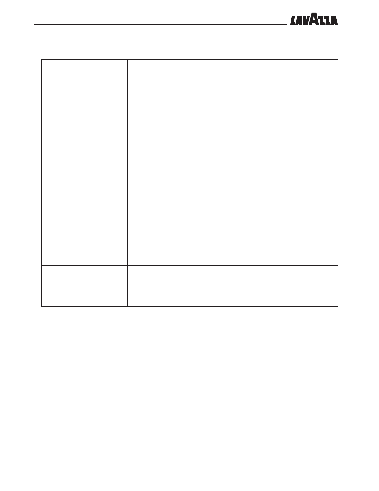
Message
BREW GROUP ERROR
EMPTY DREGDRWAWER
(WARNING)
EMPTY DREGDRWAWER
(ALARM)
CLOSE DOOR
CLOSE DREGDRAWER
PUT HOPPER
12.7 Display messages
Cause
Appears when an error occurs which can be identified by a number displayed on the service menu
at item S.2.2.1.1
Appears when the capsule drawer is almost full
(the machine has dispensed the programmed
number of beverages). Further dispensing can be
performed.
Appears when the capsule drawer is completely
full (the machine has dispensed the programmed
number of beverages). The machine is blocked
and no more dispensing can be performed until
the capsule drawer is emptied.
The door is not closed correctly.
The capsule drawer is not properly in place.
The hopper is not properly in place.
Solution
Obtain the error identification number
from the service menu, turn off the machine and call the AUTHORIZED CUSTOMER SERVICE CENTRE.
For the errors indicated below, before
calling the AUTHORIZED CUSTOMER
SERVICE CENTRE it is necessary to carry out the following checks:
52 check that water is present in the
water network;
55 check that the group is correctly in
place.
Empty the capsule drawer
Empty the capsule drawer
Close the door
Insert the capsule drawer correctly
Insert the hopper correctly
12.8 Turning off the machine
This is achieved by setting the main switch (21) in the “0” position or by
unplugging the machine.
••23
ENGLISH
F. 12
C
A
B
13 - SCHEDULED
MAINTENANCE
Warning
• For operating problems, normally reported on the display,
switch off the machine immediately, turn off the power supply using
the all-pole switch or by unplugging the machine and contact the
nearest customer service centre.
• Before carrying out any maintenance and/or cleaning
operation, disconnect the power supply using the main switch (21)
and the all-pole switch (or unplug the machine).
• All operations must be performed when the machine is cold.
• Do not perform any cleaning operation when the machine is in
“standby”.
• The cleaning products are available from all suppliers of coffee
machine spare parts. If they cannot be found locally, please ask the
principal company or the installer for assistance.
• Never wash any of the machine components in the dishwasher.
• Do not use direct jets of water.
13.1 Cleaning the machine
• Cleaning must be performed daily and if the machine will
remain inactive for a prolonged period of time, in order to avoid the
solidification of deposits in the containers, trays and dispensers.
• The removable components of the machine must be cleaned
and rinsed in tap water.
• Clean the casing, panels and machine controls using soft cloths dam-
pened with lukewarm water.
• The non-removable components and the machine must be
cleaned only with cold or lukewarm water, using non abrasive sponges and wet cloths.
• All the parts requiring cleaning are easily accessible and do not
require the use of tools.
IMPORTANT
Regular maintenance and cleaning will keep the machine in
good working order for longer as well as ensuring compliance
with basic hygiene standards.
The machine automatically warns when maintenance or
descaling operations must be carried out; the number of
beverages dispensed can be seen on the machine display; lack
of maintenance by the Maintenance Technician may cause the
machine to block.
13.1.1 Coffee dispenser (F. 12)
The following can be removed:
- the upper protection (A), of the dispenser by pulling it outwards;
- the coffee dispenser (B) by pulling it outwards;
- the coffee coupling (C) from the brew group.
13.1.2 Drip tray and relative grille
Remove the drip tray (15) and wash it in tap water, paying particular
attention to the grille.
13.1.3 Capsule drawer
Wash the capsule drawer in tap water (16 and 18) after removing it
from its seat.
13.1.4 Steam and hot water spouts
Clean the spouts (13 and 19) with a wet non abrasive cloth.
If the nozzles are clogged the end of the spouts can be unscrewed and
the nozzles re-opened using a pin.
13.1.5 Cup warming plate
Clean the cup warming plate (4) with a wet non abrasive cloth.
13.1.6 Brew Group
Remove the brew group (27) and clean it in tap water.
13.1.7 Capsule discharge hopper
Remove the capsule discharge hopper (28) and clean it in tap water.
••24
F. 14
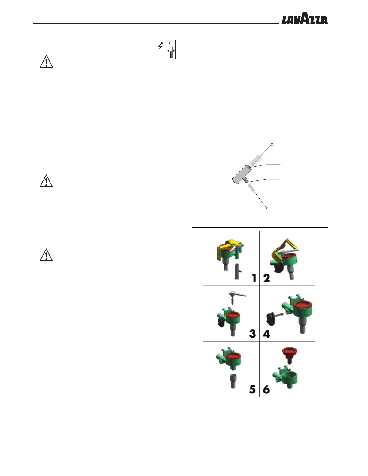
13.1.8 Cleaning the cappuccinatore
WARNING
Do not perform any cleaning operation of the cappuccinatore
when the machine is in “standby”.
The CAPPUCCINATORE must be cleaned each time it is used,
in order to avoid the solidification of deposits.
All removable components must be washed and rinsed in tap
water.
Warning! Danger of scalding. Hot water, steam sprays
and milk residue may spill out of the cappuccinatore during the
washing cycles. Do not place hands or other parts of the body
close to these parts until the cleaning cycle is complete.
The aim of this operation is to remove all the grease and scale deposits
that have formed during the flow and emulsion of the milk.
If the washing cycle is not performed, this would cause the deposits to
solidify, resulting in a loss of performance for the cappuccinatore.
WARNING
The operations described below should be performed with the
machine switched on and under pressure.
Periodic cleaning
This operation must be performed approximately every 30 minutes if the
cappuccinatore is used continuously.
- Remove the hose from the milk container and immerse it in cold water.
- Press the milk dispensing button to clean the cappuccinatore.
WARNING
It is recommended that the abovementioned cycle is performed
at least twice at intervals of one minute.
Cleaning of the cappuccinatore each evening
To be performed at the end of the working day.
- Fill a container with ½ litre of cold water and one dose of liquid
detergent (see product instructions).
- Remove the suction tube from the milk container and immerse it in the
detergent solution.
- By pressing the MILK button the water will flow out of the cappuccino
dispensing head. The message MILK will appear on the display.
Keep dispensing the milk beverage until the liquid has run out.
- The detergent will be drawn up automatically and flow out of the
cappuccinatore head.
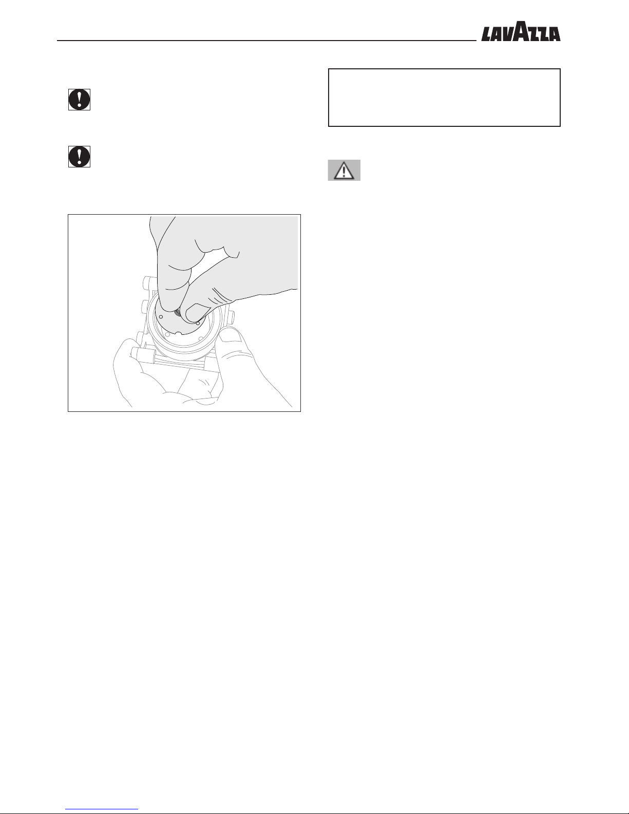
- Once the washing cycle is complete, remove the chromed cover.
- Remove the cappuccinatore (see figure 14):
- Gently pull downwards and remove the connector of the milk tube
placed at the side of the cappuccinatore.
- Remove the cappuccinatore by pulling it from the front towards you.
- Dismantle the cappuccinatore completely and disassemble the five
parts.
- Prepare a new dose of detergent solution (as above) and immerse
the parts of the cappuccinatore.
- Wash each part with a sponge and remove all organic residue,
then re-immerse the cappuccinatore in the solution for at least two
hours.
- Replace the components.
- Put the cappuccinatore back in the machine, insert the milk pipe
connector placed at the side of the cappuccinatore and replace the
chromed cover in its seat.
- Clean the holes A and B using the appropriate bottle brushes (see
figure)
F. 13
A
B
- Rinse allowing at least ½ litre of cold water to be pumped
through the cappuccinatore.
••25
ENGLISH
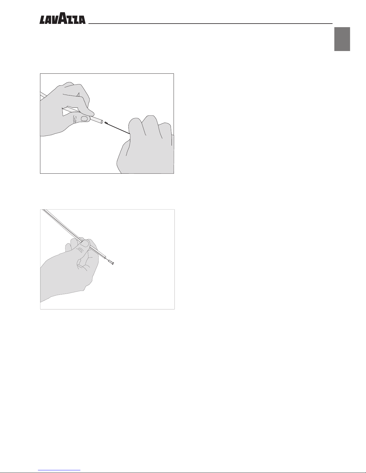
Cleaning of the cappuccinatore tube
- Remove the tube from the cappuccinatore fitting and from the milk
container
- Insert the bottle brush into the tube (see figure)
- Pull it outwards; repeat this operation at least twice
F. 15
F. 16
••26
F. 17
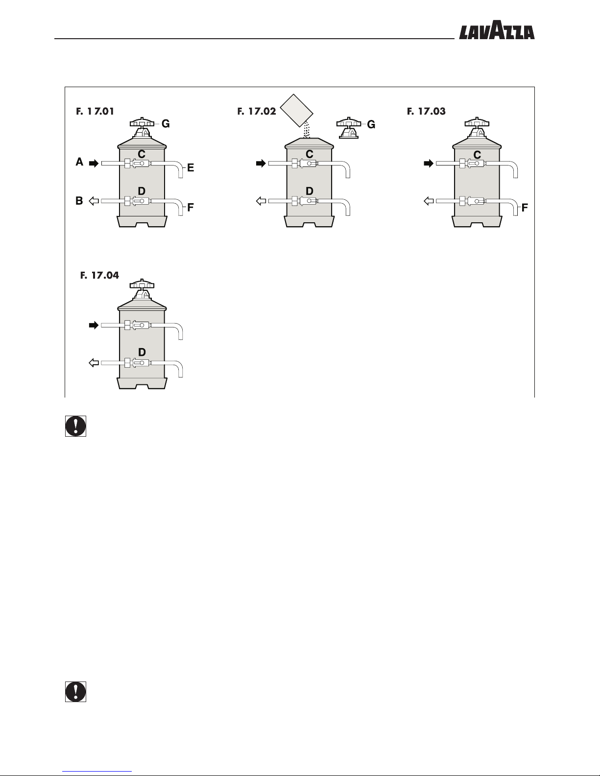
13.1.9 Regeneration of the purifier
A WATER INLET
B WATER OUTLET
C INLET TAP LEVER
D OUTLET TAP LEVER
E GROUP VACUUM UNIT
F REGENERATION PIPE
G COVER KNOB
IMPORTANT
Regenerate the purifier at the scheduled deadlines
indicated below:
HARDNESS ° F
From 00 to 20
From 21 to 30
From 31 to 40
From 41 to 50
PURIFIER TYPE 8 LITRES
regeneration after 1100 l.
regeneration after 850 l.
regeneration after 650 l.
regeneration after 450 l.
PURIFIER TYPE 12 LITRES
regeneration after 1600 l.
regeneration after 1250 l.
regeneration after 950 l.
regeneration after 650 l.
- Place an empty container with a capacity of 2 litres under the
pipe E
- Move the levers C and D from left to right as in fig. 17.02, remove
the cover by releasing the knob G, add 1.5 Kg of sodium chloride
(cooking salt), in the purifier (type 8 litres) and 2 kg in the purifier
(type 12 litres).
- Replace the cover and reposition the lever C from right to left
as in fig. 17.03 and let the salty water drain from the tap F until there
is fresh water.
- Reposition the lever D from right to left as in fig. 17.04.
IMPORTANT
The regeneration operations are correct only if the purifier
is the one shown in the figures. If it does not correspond,
proceed as indicated in the instructions attached to the
purifier.
••27
ENGLISH
PUSH
P
U
S
H
P
U
S
H
F. 18
F. 19
F. 20
F. 21
F. 22
14 - UNSCHEDULED
MAINTENANCE
IMPORTANT
Any repair and part replacements form part of the
unscheduled maintenance. They are therefore only to be
carried out by the Maintenance Technician.
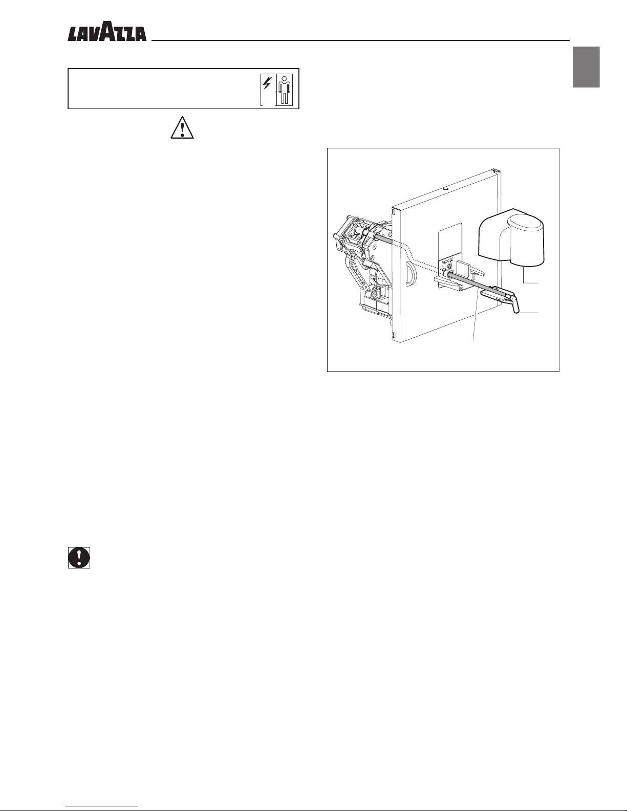
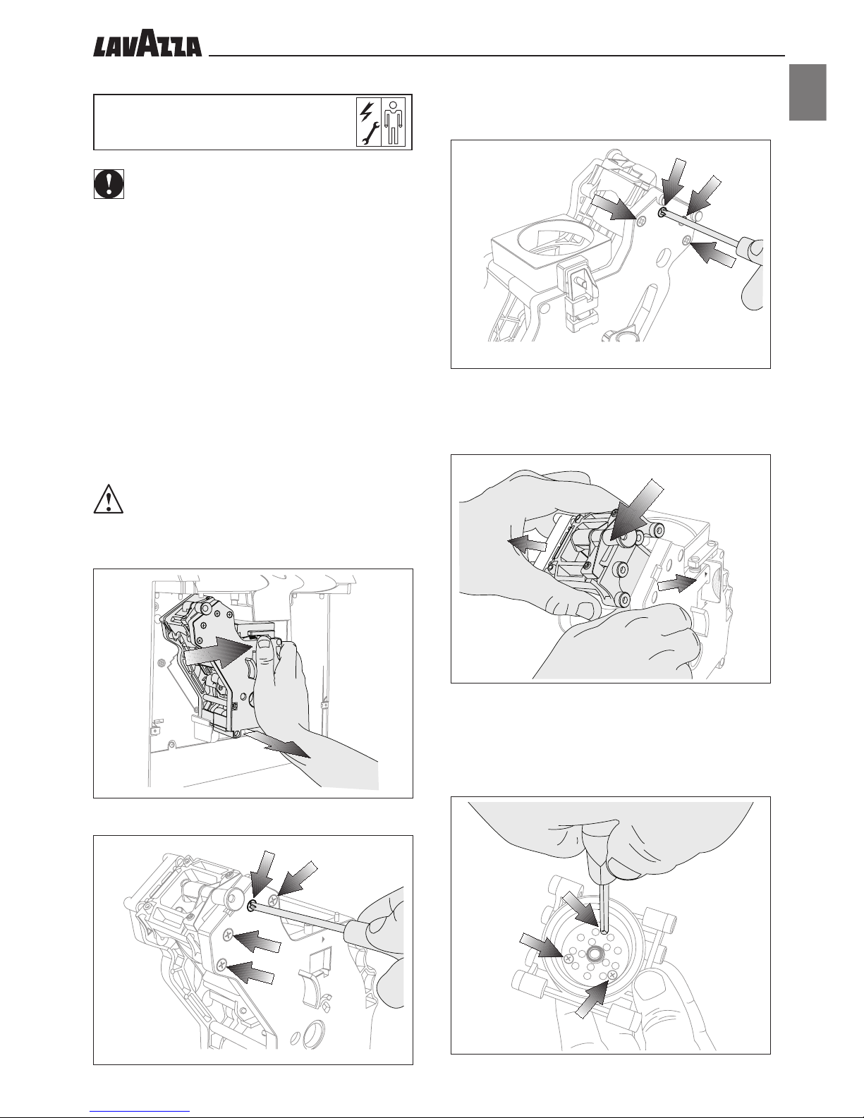
14.1 Brew group
It is recommended that the piercing filter is replaced every 40005000 cycles in order to guarantee higher quality of the coffee.
Deassembling the Piercing Filter
This section explains how to deassemble a piercing filter and
carry out maintenance on it.
Press the “PUSH” lever and remove the brew group by pulling it
outwards.
WARNING
This unit includes very sharp parts which may cause injuries
to the operator. Please be very careful when performing
maintenance operations.
Unscrew the 4 screws on the front of the brew group.
Unscrew the 4 screws located at the rear of the brew group.
Widen the walls of the brew group slightly, and take out the nonremovable container for coffee capsules.
Unscrew the 3 screws holding the perforator in place.
••28
F. 23
Remove the used perforator and put the new perforator back in place.
IMPORTANT
The perforator can be installed only in a pre-set position. To
install the perforator correctly, use the notch placed inside the
piston stop as a reference.
IMPORTANT
The perforator must be replaced if a pin is damaged.
15 - INSTRUCTIONS FOR
END-OF-LIFE DISPOSAL
TREATMENT
Warning
The diposal of the vending machine or of a part of it must be carried out
with full respect of the environment and according to local laws in force.
••29
ENGLISH
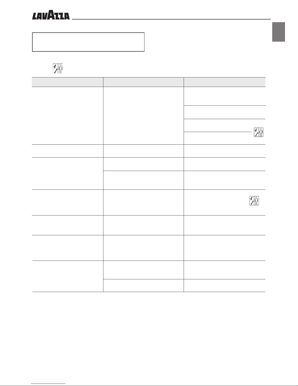
16 - TROUBLES, CAUSES
AND CURES
TROUBLE CAUSE
CURE
The machine does not start
No water or steam supply
Coffee is not hot enough
The machine requires too much
time to warm up, the water
quantity is reduced
The brew group cannot be
removed
The brew group cannot be refit
The cappuccinatore does not
dispense milk
No voltage
The steam/hot water spout’s hole is clogged
The cup has not been preheated
The machine has not yet reached the
suitable temperature
The machine circuit is clogged by scale
The brew group is not in the right position
The brew group is not in the right position
The milk used is not cold enough (see warnings)
No more milk in the container
Check:
- if the plug is connected
- if the all-pole switch (if any) is on
- the system fuses
- the electric connections
Clean it with a thin needle
Preheat the cup on the cup warming plate
Wait for the machine to reach the suitable
temperature
Descale the machine
Switch the machine on and off through the
main switch
Manually turn the group onto the standard
position, matching the reference mark placed
on the structure with the arrow
Move the temperature adjusting lever
downward
Fill milk container
Here is a list of the possible machine troubles.
The symbol in the “cure” box means that the operation must be carried out by the Maintenance Technician only.

••30
1 - COMPOSITION DE LA MACHINE ............ 3 1
2 - REMARQUES À CONSULTER....................... 3 2
2.1 Abréviations ........................................................... 32
2.2 Symboles utilisés ...................................................... 32
3 - UTILISATEUR....................................................... 3 2
4 - TECHNICIEN D’ENTRETIEN......................... 3 2
5 - UTILISATION PRÉVUE DE LA MACHINE .3 2
6 - AVERTISSEMENTS ET PRÉCAUTIONS...... 3 3
7 - PRÉCAUTIONS GÉNÉRALES ....................... 3 3
8 - INFORMATIONS SUR LA MACHINE ....... 3 3
8.1 Données d’identification .......................................... 33
8.2 Caractéristiques techniques ...................................... 33
8.3 Dimensions d’encombrement ................................... 33
8.4 Groupe de distribution de café ................................. 34
8.5 Groupe Cappuccinatore .......................................... 34
9 - DISPOSITIFS DE SÉCURITÉ ........................... 3 4
9.1 Risques résiduels ...................................................... 34
10
- INSTALLATION................................................. 3 5
10.1 Remarques sur l’emplacement ................................... 35
10.2 Mise en place de l’appareil ...................................... 35
10.3 Branchement de l’eau .............................................. 35
10.4 Raccordement électrique .......................................... 36
10.5 Connexion du port série .......................................... 36
1 1 - PREMIÈRE MISE EN CIRCUIT DE LA MACHINE. 3 6
12
- EMPLOI DE LA MACHINE ............................ 3 6
12.1 États de la machine ................................................. 36
12.2 Description des commandes ..................................... 37
12.3 Fonctions programmables du menu .......................... 39
12.4 Structure du menu de programmation ....................... 39
12.5 Description des fonctions......................................... 40
12.6 Structure du menu de service .................................... 45
12.7 Messages affichés .................................................... 49
12.8 Mise hors circuit de la machine ................................ 49
13
- ENTRETIEN DE ROUTINE .............................. 5 0
13.1 Nettoyage de la machine ......................................... 50
13.1.1 Distributeur de café (Fig. 12) .................................... 50
13.1.2 Bac et grille égouttoir .............................................. 50
13.1.3 Bac à capsules......................................................... 50
13.1.4 Tuyaux de distribution de vapeur et d’eau chaude ..... 50
13.1.5 Plaque chauffe-tasses ............................................... 50
13.1.6 Groupe de distribution ............................................. 50
13.1.7 Trémie d’éjection capsule ......................................... 50
13.1.8 Nettoyage du cappuccinatore .................................. 51
13.1.9 Régénération adoucisseur ........................................ 53
14
- ENTRETIEN CURATIF ...................................... 5 4
14.1 Groupe de distribution............................................. 54
15
- INSTRUCTIONS POUR LE TRAITEMENT
DE FIN DE VIE UTILE....................................... 5 5
16
- INCONVÉNIENTS - PROBLÈMES ET SOLUTIONS .............. 5 6
AVANT-PROPOS
• Ce manuel fait partie intégrante de la machine et il est donc à garder dans de bonnes conditions, dans un endroit facilement accessible
pendant toute la vie opérationnelle de la machine (compte tenu des passages de propriété aussi). L’objectif de ce manuel est le passage
d’informations nécessaires pour l’utilisation correcte et en toute sécurité de la machine.
• En cas de perte ou bien de détérioration de ce manuel, s’adresser à un Centre d’Assistance Agréé, afin d’en demander une copie,
et préciser le modèle et l’année de fabrication de la machine.
• Les Centres d’Assistance Agréés sont également disponibles pour tout renseignement concernant les aspects techniques, le fonction-
nement, l’assistance technique et les pièces de rechange.
• Les sujets présentés dans ce manuel sont valables pour l’utilisation de la machine dans des conditions de sécurité pour les
personnes, la machine et l’environnement, dans l’interprétation d’un simple diagnostic des endommagements et des conditions de
fonctionnement anomal, en effectuant de simples opérations de contrôle et d’entretien, dans le respect absolu des prescriptions reportées
dans les pages suivantes et des Normes de Sécurité et de Santé en vigueur.
• Avant d’effectuer toute intervention, lire attentivement le manuel et s’assurer d’en avoir bien compris le contenu.
• Si la machine est employée (individuellement) par plusieurs utilisateurs, il faut absolument que chaque utilisateur connaisse en détail
le mode d’emploi.
• Le Constructeur se réserve le droit de modifier ou bien d’effectuer des améliorations de la machine sans préavis.
• En cas d’exigences spéciales, s’adresser au Distributeur ou à l’Importateur (si présent) de son pays ou bien au Constructeur de la
machine.
• Tous les droits de ce manuel sont strictement réservés à la Maison LAVAZZA. La reproduction ou la diffusion, même en partie, sans
autorisation écrite, sont interdites.
TABLE DES MATIÈRES
 Loading...