

Lathem PC3500TX User Manual

PC3500TX Terminal
Installation &
User’s Guide

Limited One-Year Limited Warranty
Lathem warrants the hardware products described in this guide against defects in material and workmanship for a
period of one year from date of original purchase from Lathem or from an authorized Lathem reseller. The
conditions of this warranty and the extent of the responsibility of Lathem Time Corporation (“Lathem”) under this
warranty are listed below.
1. This warranty will become void when service performed by anyone other than an approved Lathem
warranty service dealer results in damage to the product.
2. This warranty does not apply to any product which has been subject to abuse, neglect, or accident, or
which has had the serial number altered or removed, or which has been connected, installed, adjusted,
or repaired other than in accordance with instructions furnished by Lathem.
3. This warranty does not cover dealer labor cost for removing and reinstalling the machine for repair,
or any expendable parts that are readily replaced due to normal use.
4. The sole responsibility of Lathem under this warranty shall be limited to repair of this product, or
replacement thereof, at the sole discretion of Lathem.
5. If it becomes necessary to send the product or any defective part to Lathem or any authorized service
dealer, the product must be shipped in its original carton or equivalent, fully insured with shipping
charges prepaid. Lathem will not assume any responsibility for any loss or damage incurred in
shipping.
6. WARRANTY DISCLAIMER AND LIMITATION OF LIABILITY: Except only the limited express
warranty set forth above, the products are sold with no expressed or implied warranties of any kind,
and the implied warranties of merchantability and fitness for a particular purpose are hereby
expressly disclaimed. No warranties are given with respect to products purchased other than from
Lathem or an authorized Lathem reseller and any such products are purchased "as is, with all faults."
In no event will Lathem be liable for any direct, indirect, special, incidental or consequential damages
arising out of or in connection with the delivery, use or inability to use, or performance of this
product. In the event any limited remedy given herein shall be deemed to have failed of its essential
purpose, Lathem's maximum liability shall be to refund the purchase price upon return of the product.
7. Proof of date of purchase from Lathem or an authorized Lathem reseller is required for warranty
service on this product.
8. This Warranty grants specific legal rights. Additional legal rights, which may vary by locale, may
also apply.
9. Should any difficulties arise with the performance of this product during warranty, or with any
Lathem authorized service centers, contact Lathem Time at the address below.
Lathem Time
200 Selig Drive, SW, Atlanta, GA 30336
404-691-0405
www.lathem.com
Copyright © 2003 Lathem Time Corporation. All rights reserved.
Document number: USG0031I
Revised 8-04-2006

PayClock, Lathem and the Lathem logo are registered trademarks of Lathem Time Corporation. Other product names
mentioned in this manual may be trademarks of their respective companies and are hereby acknowledged.
Warning: Changes or modifications to this unit not expressly approved by the party responsible for compliance could void
the user’s authority to operate the equipment.
NOTICE: This equipment has been tested and found to comply with the limits for a Class A digital device, pursuant
to Part 15 of the FCC Rules. These limits are designed to provide reasonable protection against harmful interference
when the equipment is operated in a commercial environment. This equipment generates, uses, and can radiate radio
frequency energy and, if not installed and used in accordance with the instructional manual, may cause harmful interference
to radio communications. Operation of this equipment in a residential area is likely to cause harmful interference in which
case the user will be required to correct the interference at his or her own expense.

CONTENTS
WELCOME.....................................................................................................................................1
FEATURES AND SPECIFICATIONS....................................................................................................1
MOUNTING THE TERMINAL...................................................................................................3
PRE-TERMINAL INSTALLATION......................................................................................................3
MOUNT THE TERMINAL .................................................................................................................3
CONNECT THE COMMUNICATION CABLE.........................................................................6
SETUP THE TERMINAL.............................................................................................................7
SETUP MODE .................................................................................................................................9
To Setup the PC3500TX’s Ethernet Communications....................................................................9
TEST MODE .................................................................................................................................15
To Test the Keypad..........................................................................................................................15
To Test the Badge Reader................................................................................................................15
Battery Test.......................................................................................................................................16
DI-DO Test........................................................................................................................................16
Restart Mode ....................................................................................................................................17
UNLOCKING YOUR TERMINAL THROUGH TERMINAL MANAGER.................................................17
USE THE TERMINAL................................................................................................................18
To punch .................................................................................................................................18
To transfer ..............................................................................................................................19
To start a New Day.................................................................................................................19
To enter amounts ....................................................................................................................19
To reveiw your last punch.......................................................................................................19
To see employee Info...............................................................................................................20
SUPERVISOR FUNCTIONS .............................................................................................................20
To Add an Employee Punch ....................................................................................................20
INSTALL/REPLACE THE OPTIONAL BACKUP BATTERY.............................................21
OPTIONAL SIGNAL DEVICE..................................................................................................22
NETWORK WIRING TOPOLOGIES.......................................................................................23
TROUBLESHOOTING THE TERMINAL...............................................................................25
TERMINAL DATA SHEET........................................................................................................29

CHAPTER 1
Welcome
Reliability, functionality and ease of use are trademarks of the PayClock terminals. Using
Lathem time and attendance software and your computer, PayClock terminals are the
perfect solution for businesses that want to track employee time and automate payroll.
PC3500TX NOTICE – For Firmware 177B and Earlier
¾Windows 98 2nd edition or later is required
¾PayClock Pro version 3.353 to 3.355G is required
PC3500TX NOTICE – For Firmware 177G and Later
¾Windows 2000 or Windows XP is required
¾PayClock Pro version 4.1 or later is required
Features and Specifications
Display: 4 Line x 20 Character back-lit super-twist LCD
Terminal: 12 or 24 hour-format, USA or International, quartz-precision Time-
Stamp on data transactions
Indicators: LED’s indicate low Power (yellow), Invalid registration (red) and
Valid registration (green).
Diagnostic LEDs for Ethernet, Busy (yellow), Linked (green),
Receive (yellow), Transmit (red)
Communications: TCP/IP ETHERNET 10-base-T compatible
Input: Keypad and bar code slot reader. Badges are bar code format 3 of 9
or Interleave 2 of 5
Casing: Die cast aluminum housing with steel key-lockable mounting plate.
Large 20 key tactile 4x5 matrix keypad. 9.75" wide X 7.25" high X
3.8" deep, 6 LBS
Power: +10 to +17VDC (+12VDC @ 250 milliamps Nominal). An optional
non-interruptible power supply (UPS) provides operation for up to 4
hours during power outages
Environment: Operation: 32° to 110° F (0° to 43° C)
Certification: CE Mark Certified (CE, RE, ESD, RS and CS), FCC part 15
PC3500TX Terminal Installation & User’s Guide - 1

2 - PC3500TX Terminal Installation & User’s Guide
Cable Specs: Category 4 or Category 5 unshielded twisted pair high-speed data
transmission cable. Note: All cables must conform to local
building/electrical codes. Consult a qualified installer
Capacities: Employee 600
Departments 290
Transactions 900 (approximate)
Power Surges and Spikes
Any time your terminal is connected to AC current, a power surge or spike can occur.
You should use high quality surge suppressers to protect your PC3500TX. The warranty
does not cover damage caused by power surges or spikes.
Note about Lithium Battery
This product’s lithium battery contains Perchlorate Material – special handling may
apply. Please go to web site www.dtsc.ca.gov/hazardouswaste/perchlorate for
information about proper methods of disposal in California.

PC3500TX Terminal Installation & User’s Guide - 3
CHAPTER 2
Mounting the Terminal
Pre-Terminal Installation
Before deciding where to mount the terminal, you will need to verify that it will be
within 4 feet of an 115VAC power outlet. The outlet should not be located near devices
that may cause interference on the line such as refrigerators, microwave ovens, welders,
etc.
The PC3500TX may be located at any point within a TCP/IP Ethernet 10-Base-T
network, as long as the section of cable between the network switch and PC3500TX does
not go beyond three hundred and twenty eight (328) wire-feet. A typical topography for
the PC3500TX in an Ethernet 10-Base-T network is a star configuration.
NOTE: It is recommended that the PC3500TX be plugged into a switch.
Included with the terminal is a label that is used to note specific information about the
terminal. This information should be written on the sticker and placed on either side or
the bottom of the terminal. This will be used when the terminal is setup or in
troubleshooting. The information will come from your Network Administrator.
This information includes the terminals: IP Address (this must be a static
Subnet Mask and Gateway. This information should also be written on the Terminal Data
Sheet found near the end of this document.
NOTE: Lathem representatives cannot issue or obtain this information. You must see
your network administrator prior to beginning the installation for this information.
IP address),
Mount the Terminal
The PC3500TX is designed to operate indoors. You should use the terminal where the
temperature is between 32°-110° F and humidity is less than 95%. You should choose a
place where the terminal cannot vibrate. Exposure to outdoor conditions such as rain or
snow voids the warranty and can damage the terminal.
4 - PC3500TX Terminal Installation & User’s Guide
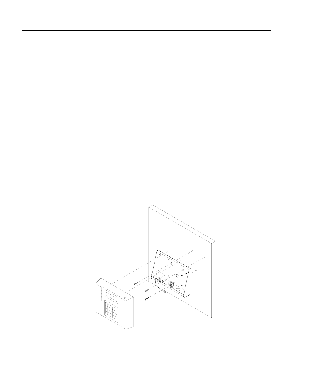
To install the mounting bracket
♦ Locate a flat wall surface. Make sure you can plug the terminal into a 110VAC wall
outlet (220VAC in Europe and other areas), which should be no farther than 4 feet
from the terminal.
♦ Place the bottom of the mounting template on the wall 48 inches from the floor and
tape the template into place.
♦ Drill the 3 holes noted on the template using a 5/16” drill bit. If wires will be ro uted
through the wall, drill up to a 3/4" hole as indicated on the template. Remove the
template.
♦ Insert a wall anchor in each of the 5/16" holes and tap with a hammer until flush
with the wall.
♦ Align the mounting bracket with the anchors, (pull wiring through the hole in the
middle of the case if wires are being routed from the wall), insert the 3 screws and
tighten with a phillips head screwdriver.

PC3500TX Terminal Installation & User’s Guide - 5
♦ If all wiring is not routed from the wall, remove one of the mounting bracket
knockouts, so you can run the communication cable and 12VDC power pack cable
to the terminal.
♦ Insert the key into the mounting bracket lock and turn the key counter clockwise.
♦ Align the slots on the back of the terminal with the tabs on the top of the mounting
bracket. Plug in the power pack and communications cable, then lower the terminal
into place.
♦ Turn the key clockwise to lock the terminal in place.
6 - PC3500TX Terminal Installation & User’s Guide
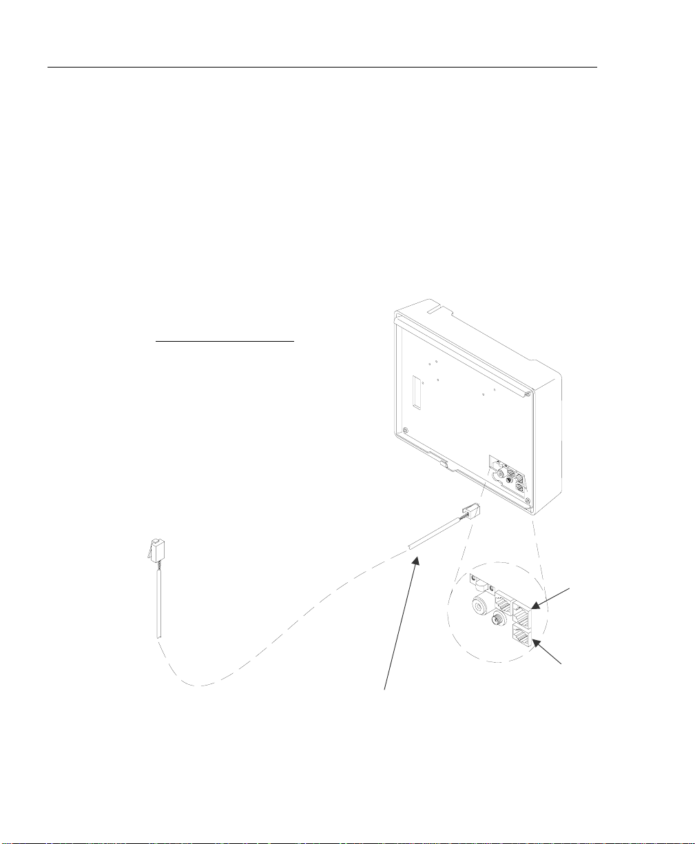
port
CHAPTER 3
Connect the Communication Cable
For Ethernet communications, CAT 4 or 5 unshielded twisted pair high-speed data
communication cable is recommended. An RJ45 plug should be attached as shown in the
diagram below. Once the plug is attached to the cable, unlock and remove the terminal
from the mounting bracket. Route the cable through the desired knockout of the
mounting plate and plug the RJ45 plug into the Ethernet Communication port as shown
below.
Typical Ethernet Pin Out
Pin 1 --- White / Orange
Pin 2 --- Orange
Pin 3 --- White / Green
Pin 4 --- Blue
Pin 5 --- White / Blue
Pin 6 --- Green
Pin 7 --- White/ Brown
Pin 8 --- Brown
Network cable with RJ-45 connector
coming from network switch
Ethernet
communication
DI-DO Connector
 Loading...