

Page 1

LSW2F8, LSW2F16
10/100 Ethernet
Switch
Installation Guide
Page 2

Table of Contents
CHAPTER 1. Introduction
1.1 Product Introduction. . . . . . . . . . . . . . . . . . . . . . . . . . . . . . . 2
1.2 Features . . . . . . . . . . . . . . . . . . . . . . . . . . . . . . . . . . . . . . . . . 3
1.3 Product Specifications . . . . . . . . . . . . . . . . . . . . . . . . . . . . . . 4
CHAPTER 2. Using the LSW Switch
2.1 Packing Checklist. . . . . . . . . . . . . . . . . . . . . . . . . . . . . . . . . . 5
2.2 Planning Your Network . . . . . . . . . . . . . . . . . . . . . . . . . . . . 5
2.2.1 Fileserver Link . . . . . . . . . . . . . . . . . . . . . . . . . . . . . . . . . . 6
2.2.2 Backbone Link. . . . . . . . . . . . . . . . . . . . . . . . . . . . . . . . . . . 7
2.2.3 10/100Mbps Bridge . . . . . . . . . . . . . . . . . . . . . . . . . . . . . . 8
2.3 Installation . . . . . . . . . . . . . . . . . . . . . . . . . . . . . . . . . . . . . . . 8
2.4 Mounting . . . . . . . . . . . . . . . . . . . . . . . . . . . . . . . . . . . . . . . 10
2.5 Connecting the LSW Switch . . . . . . . . . . . . . . . . . . . . . . . . 11
CHAPTER 3. LED Indicators
3.1 Power LED . . . . . . . . . . . . . . . . . . . . . . . . . . . . . . . . . . . . . . 12
3.2 10/100 Mbps LEDs . . . . . . . . . . . . . . . . . . . . . . . . . . . . . . . 12
3.3 Full/Col: Full or Half Duplex/Collision LEDs. . . . . . . . . 13
3.4 Link/Activity LEDs. . . . . . . . . . . . . . . . . . . . . . . . . . . . . . . 13
Limited Warranty. . . . . . . . . . . . . . . . . . . . . . . . . . . . . . . . . 14
Technical Support . . . . . . . . . . . . . . . . . . . . . . . . . . . . . . . . 14
Declaration of Conformity . . . . . . . . . . . . . . . . . . . . . . . 16
1
Page 3

CHAPTER 1 Introduction
1.1 Product Introduction
Congratulations on your purchase of the Lantronix 10/100Mbps 10port or 18-port switch. The LSW2F8 and LSW2F16 10/100 Ethernet
Switches are designed to give you the ultimate in performance, flexibility, ease-of-use, and reliability.
The LSW 10/100 switches can increase performance on your network
by bringing full Ethernet bandwidth to individual workgroups or
straight to the desktop instead of requiring all stations to share the
bandwidth of a single network. The LSW switchÕs 100Mbps Fast
Ethernet capability can eliminate bottlenecks in connection to servers,
or can link 10Mbps workgroups to a 100Mbps Fast Ethernet network
backbone.
For straight-through 10BASE-T/100BASE-TX connections to servers
and workstations, the LSW switches support full-duplex connections,
effectively doubling the total throughput on individual links. The LSW
switchÕs store-and-forward switching architecture forwards packets to
their destination with a minimum of delay and eliminates bad packets
from the network.
The LSW2F8/LSW2F16 switch can be placed on a tabletop or rackmounted, and provides the ideal solution for your small, medium, or
large Ethernet/Fast Ethernet network. These devices are designed to
comply fully with the IEEE 802.3 Ethernet and 802.3u Fast Ethernet
standards.
2
Page 4

1.2 Features
▼ The LSW2F8 provides two 100BASE-TX ports and eight 10BASE-T
ports for Ethernet and Fast Ethernet connectivity
▼ The LSW2F8/LSW2F16 comply with the IEEE 802.3 Ethernet and
IEEE 802.3u Fast Ethernet standards
▼ An Uplink switch on the front panel enables the LSW switch to be
cascaded to another 10Mbps or 100Mbps hub using a straightthrough cable
▼ Store-and-forward switching architecture for filtering bad packets
▼ Total bandwidth up to 280Mbps (LSW2F8I) and 360Mbps (LSW2F16)
▼ Automatic address learning with 8K addresses per port
▼ MemoryÐLSW2F8: 1MB total
LSW2F16: 3MB total
▼ Per-port frame filtering and forwarding capability
▼ Filtering and forwarding rate 14880 packets per second for 10Mbps
ports, 148800 per second for 100Mbps ports
▼ Global Power and individual Collision, Link/Activity LEDs
monitor system status
▼ The internal power supply automatically adjusts to the voltage
range of the AC power being supplied (100VAC/60Hz to
240VAC/50Hz), with no change in settings or fuse required
▼ FCC Class A, CE, UL, CUL, TUV certifications
▼ Five year limited warranty
3
Page 5

1.3 Product Specifications
Standards IEEE 802.3 10BASE-T Ethernet
IEEE 802.3u 100BASE-TX Fast Ethernet
Architecture Store and forward switching
Connectors LSW2F8 8x10BASE-T/2 100BASE-TX (RJ-45) Fast
Ethernet ports
LSW2F16 16x10BASE-T/2 100BASE-TX (RJ-45) Fast
Ethernet ports
Uplink ports Push button to select Uplink or Normal
connections: Port 1 and Port 10
Duplex mode Autonegotiates to highest setting on 10/100 ports
(Ports 1 and 2)
Switch-selectable on 10Mbps ports
LED indicators Power (device)
Link/Act, Full/Col (per port)
Power 100Ð240VAC, 50/60Hz
EMI Approval FCC Class A, CE, UL, CUL, TUV
Dimensions 220mm x 330mm x 44mm (L x W x H)
Environment Operating: 0¡C to 40¡C, 10% to 80% humidity
Storage: -20¡C to 70¡C, 5% to 90% humidity
Warranty 5-year limited
4
Page 6

Chapter 2 Using the LSW Switch
2.1 Packing Checklist
Your switch product package should contain the following:
✓ An LSW2F8 or LSW2F16 10/100 Ethernet Switch
✓ One AC Power Cable
✓ Four self-adhesive standoffs
✓ Rackmount brackets and screws
✓ Installation Guide
If any of these items are missing, contact your dealer immediately.
2.2 Planning Your Network
Before you install your 10/100Mbps network, you should plan out
how you wish to organize your network to take maximum advantage
of its switching capabilities. This section discusses typical applications
for the switch.
5
Page 7
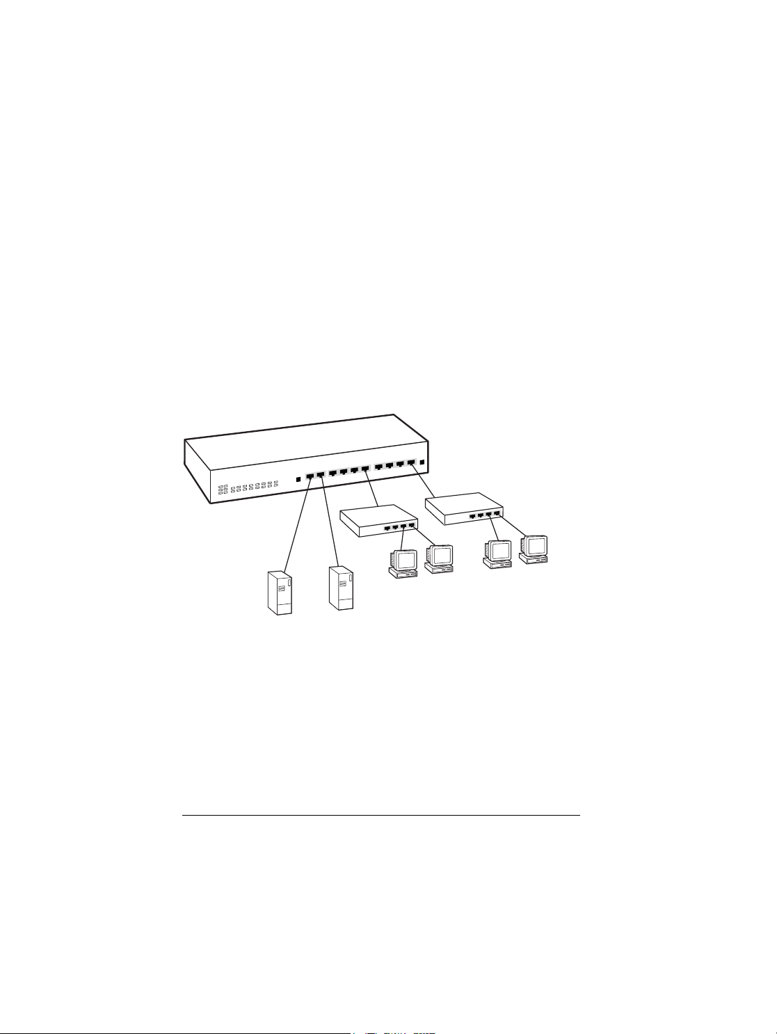
2.2.1 Fileserver Link
FULL/COL
LINK/ACT
12 3456 78910
The LSW switch can be used to greatly increase the bandwidth between
one or more fileservers and the workgroups they serve. Individual
10Mbps workgroup switches can be connected to the ports on the LSW
switch, ensuring that traffic in one workgroup will not interfere with
the performance of another workgroup. Full-duplex 100Mbps links to
fileservers guarantee that full bandwidth is delivered to each workgroup. High-performance workstations needing extra throughput can
connect directly to the switch using a full-duplex 10BASE-T connection,
giving 20Mbps of effective throughput.
Figure 2-1 Fileserver Link Application
LSW2F8
Fileserver
(100Mbps)
Hub
Hub
Workgroups
Fileserver
(100Mbps)
6
Page 8

2.2.2 Backbone Link
FULL/COL
LINK/ACT
FULL/COL
LINK/ACT
12 3456 78910
Traditionally, bridges and routers have been used to link individual
local area networks into an interconnected network. Routers and traditional bridges introduce relatively large delays when forwarding traffic
from one network to another, in addition to being difficult to manage.
Bridge architecture based on two-port bridges may require traffic to
pass through several bridges before reaching its destination. Ethernet
switches now perform these functions with especially small delays,
making them ideal for backbone link applications. Compared to
routers, LantronixÕs LSW Ethernet switches are easy to set up and
maintain. Several networks can be connected together with a single
Ethernet switch, and the forwarding delay is negligible. One or more of
the LSW switchÕs 100Mbps links can be used as a high-speed backbone
link to other switches serving as collapsed backbones.
Figure 2-2 Collapsed Backbone Application
LSW2F16
To 100Mbps
Ethernet Backbone
Fileserver
(100Mbps)
Hub
Workgroup
(10Mbps shared)
7
Hub
Workgroup
(10Mbps shared)
Page 9

2.2.3 10/100Mbps Bridging
FULL/COL
LINK/ACT
12 3456 78910
The LSW 10/100 Ethernet Switch can allow you to gradually transition
between traditional 10Mbps Ethernet and newer 100Mbps Fast
Ethernet. The addition of the LSW switch can give immediate increases
in performance on the 10Mbps networks, and allows connectivity to be
maintained when network stations are transitioned over to 100Mbps
Fast Ethernet.
Figure 2-3 10/100Mbps Bridge Application
LSW2F8
Hub
10Mbps
Hub
100Mbps
10Mbps
Hub
10BASE-T
Workgroup
100BASE-TX
10BASE-T
Workgroup
Workgroup
2.3 Installation
The LSW 10/100 Ethernet Switch is easy to install and requires no
special training. You should, however, read the following instructions
carefully before proceeding to install your switch. Figure 2-4 and Figure
2-5 show the layout of the front panels.
8
Page 10

Figure 2-4 LSW2F8 Switch Front Panel
1 2 3 4 5 6 7 8 9 10
12 3 45678910
Uplink
PWR
FULL/COL
LINK/ACT
PORT NO.
10/100 Mbps
LSW2F8
10/100
Uplink
1 2 3 4 5 6 7 8 9 10
11 12 13 14 15 16 17 18
12 3 45678910
11 12 13 14 15 16 17 18
PORT NO.
FULL/COL
LINK/ACT
PWR
FULL/COL
LINK/ACT
PORT NO.
10/100 Mbps
LSW2F16
10/100
Uplink
Uplink
Figure 2-5 LSW2F16 Switch Front Panel
The LSW 10/100 switches were designed for easy Òplug and playÓ
installation. Before you connect your switch to other devices, there are
several issues you should keep in mind:
▼ When connecting the LSW switch to a device using unshielded
twisted pair cable, you must make sure that the cable length is not
greater than 100 meters
▼ 10BASE-T Twisted Pair Ethernet cabling should be Category 3 or better
▼ 100BASE-TX Twisted Pair Fast Ethernet cabling should use tested
Category 5 cabling
▼ Network cable segments can be connected to or disconnected from
the LSW 10/100 switch while the power is on
▼ When placing your LSW switch, you need to avoid dusty locations
and electromagnetically noisy areas
9
Page 11
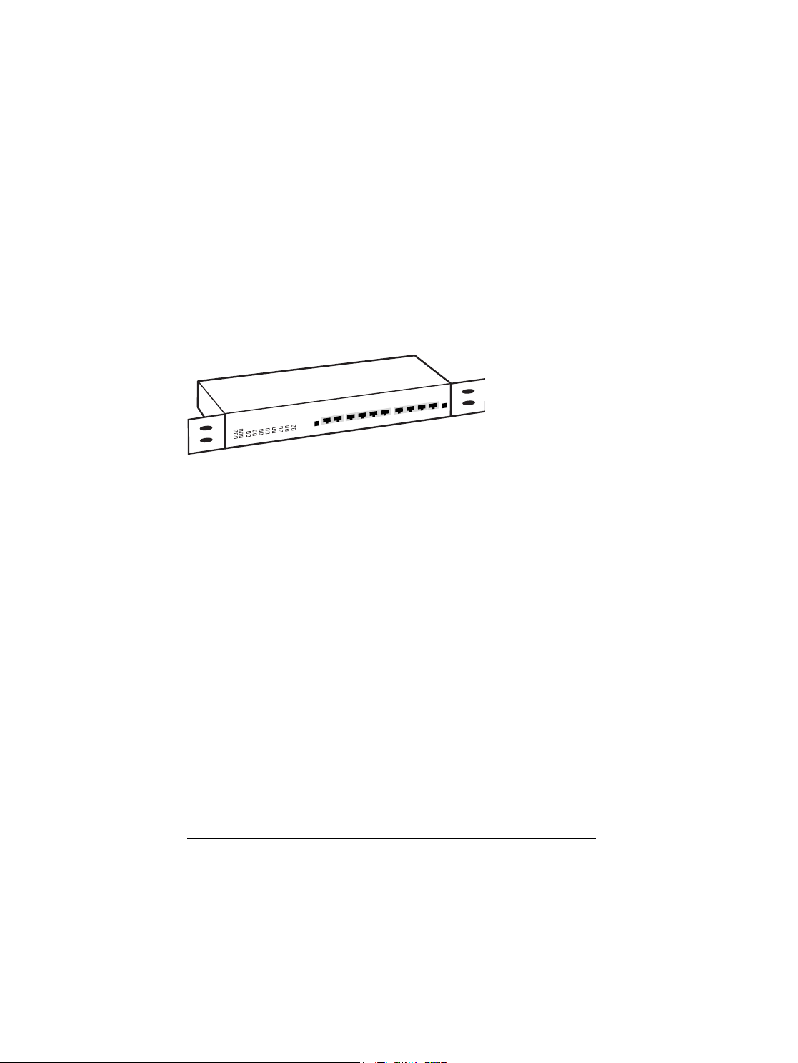
2.4 Mounting
FULL/COL
LINK/ACT
12 3456 78910
Your LSW2F8 or LSW2F16 switch is delivered with two brackets for
mounting the switch in an EIA standard 19-inch rack. Secure the
mounting brackets onto the sides of the LSW switch, fastening them
with screws as shown in Figure 2-6.
Figure 2-6 Mounting Bracket Installation
LSW2F8
If your site uses only a few switches and is not equipped with a
mounting rack, you may choose to place the LSW switch on a table or
wiring closet shelf. In this case, use the four self-adhesive rubber feet,
which are provided with the switch for cushioning purposes. Stick
them at the four corners of the bottom surface of the LSW switch to
cushion it against vibration.
10
Page 12

2.5 Connecting the LSW Switch
Use the following procedures to connect 10BASE-T or 100BASE-TX network devices to the LSW switch:
LSW2F8 Ports 2-9 Port 1 & Port 10
LSW2F16 Ports 2-18 Normal Uplink
PC, Workstation S S C
Server S S C
Hub, Switch port C C S
Hub, Switch uplink port S S C
S = Straight Cable C = Crossover cable
The following table describes the two cable types:
Straight cable Crossover cable
Pin 1 TD+ RD+
Pin 2 TD- RD-
Pin 3 RD+ TD+
Pin 6 RD- TD-
Make sure that the length of the straight-through cable between the
switch and the other device does not exceed 100 meters, including all
patch cables and cross-connect wires.
Duplex mode: each 10/100 port (Ports 1 and 2) can detect duplex mode
automatically Ð the device being connected to must support 802.3u
autonegotiation for full duplex to be used; duplex mode for 10Mbps
ports can be selected via switches on the back of the unit.
11
Page 13

Chapter 3 LED Indicators
12 34567 8910
11 12 13 14 15 16 17 18
PORT NO.
FULL/COL
LINK/ACT
PWR
FULL/COL
LINK/ACT
PORT NO.
10/100 Mbps
LSW2F16
10/100
Figure 3-1 shows the LED indicators, which indicate the link status of
each of the ports, whether the LSW switch is receiving power, and the
presence of network activity and collisions on the network.
Figure 3-1 LSW2F16 Front Panel LED Indicators
FullDuplex/Collision
Link/Activity
10/100Mbps
3.1 Power LED
The LED on the front panel labeled PWR is used to indicate that the
switch is receiving power and is turned on. If the LED is off, check the
following to isolate the problem:
▼ Make sure the power cord is properly connected to the power outlet
and is properly inserted into the power connection on the switch
▼ Determine whether or not the outlet is functional by plugging
another device into the receptacle
▼ Turn the power switch to the ON position. If there are no problems
and the LED still does not light, contact your dealer
Full-
3.2 10/100 Mbps LEDs
Each 10/100 port (Ports 1 and 2) have the 10/100Mbps LED on the front
panel. When the LED is ON, it indicates the port is in 100Mbps mode.
Otherwise, its working in 10Mbps mode.
12
Page 14

3.3 Full/Col: Full or Half Duplex/Collision LEDs
Each port has a full duplex/half duplex/Collision LED on the front
panel labeled Full/Col. On normal status, this LED indicates that transmission of selected ports is full duplex or half duplex (ON: Full duplex,
OFF: Half duplex). Also this LED is used to indicate collision status.
When two or more stations on the network segment attempted to transmit at the same time, a collision occurs, all of the stations involved in
the collision will recognize the collision, wait a random amount of time,
and retransmit. At this moment, this LED will blink on briefly.
3.4 Link/Activity LEDs
Each port on the LSW2F8 and LSW2F16 has a Link/Activity LED
which indicates whether a device is detected on the other end.
When the port is in Link OK status, this LED also used to indicate
activity on the network segment. Whenever data is transmitted and/or
received through the network segment that the port is connected to, the
LED should blink on briefly.
LED summary table
PWR Green ON=Unit is receiving power
10/100Mbps Green ON=100Mbps; OFF=10Mbps
Full/Col Yellow ON=Full Duplex; OFF=Half Duplex;
Flashing=Collision
Link/Act Green ON=Good Link; Flashing=Activity
13
Page 15

Limited Warranty
The LSW2F8 and LSW2F16 come with 5-year limited warranties. To
obtain LantronixÕs full warranty statement or if you experience problems with your unit, check our website (www.lantronix.com) or call
Lantronix for assistance.
Copyright © 1998, Lantronix. All rights reserved. No part of the contents of this guide may be transmitted or reproduced in any form or by
any means without the written permission of Lantronix.
Technical Support
If problems occur during product operation, please check the adaptor
configuration settings, cables, connectors, network terminators and other
network components for compatibility.
Write a description of the problem, including what problems occurred and
when they occurred. Also, please have the following information ready
if calling for support services:
Model number & serial number
Purchase date
Network configuration
Application environment
Hardware, software (NOS) and the DOS version
Contact Lantronix technical support at 800-422-7044 within the United
States or 949-453-3990 outside of the United States. LantronixÕs technical support can also be reached via email at support@lantronix.com,
and via the World Wide Web at www.lantronix.com or via fax
at 949-450-7226.
14
Page 16

WARNING!
This device complies with part 15 of the FCC rules. Operation is subject
to the following conditions: (1) this device may not cause harmful
interference, and (2) this device must accept any interference received,
including that which may cause undesired operation. Operation of this
equipment in a residential area is likely to cause interference in which
case the user, at his or her own expense, will be required to take whatever measures may be required to correct the interference.
NOTE: The RJ45 ports are not for telephone use.
CAUTION:
Not for installation in air ducts, plenums or other environmental
air handling spaces. Changes or modifications to this device not
explicitly approved by Lantronix will void the userÕs authority
to operate this device.
15
Page 17

Declaration of Conformity
(according to ISO/IEC Guide 22 and EN 45014)
ManufacturerÕs Name: Lantronix
ManufacturerÕs Address: 15353 Barranca Parkway
Irvine, CA 92618 USA
declares, that the product:
Product Name: 10/100 Ethernet Switches
Model Number: LSW2F8, LSW2F16
conforms to the following standards:
EMC: EN55022(1988)/CISPR 22(1985) Class B
EN60555-2(1987) Class A
prEN55024-2(1990)/IE801-2(1991) 4KV CD, 8KV AD
prEN55024-3(1991)/IE801-3(1984) 3V V/m
prEN55024-4(1992)/IE801-4(1988) 1KV - (power line)
0.5KV - (signal line)
ManufacturerÕs Contact: Director of Quality Assurance
Lantronix
15353 Barranca Parkway
Irvine, CA 92618 USA
Tel: 949-453-3990
Fax: 949-453-3995
16
Page 18

949-453-3990
15353 Barranca Parkway, Irvine, CA 92618
▼ Fax: 949-453-3995 ▼ Sales: 800-422-7055 ▼ Support: 800-422-7044
PARTNO. 900-140 Rev.A
 Loading...