

Page 1

The information in this guide may change without notice. The manufacturer assumes no responsibility for any errors which may appear in this guide.
DEC, thickwire, thinwire, VMS, VT100, and ULTRIX are trademarks of Digital Equipment Corporation. UNIX is a registered trademark of AT&T. Ethernet is a trademark of
XEROX. NetWare is a trademark of Novell Corp. AppleTalk, Chooser and Macintosh are
trademarks of Apple Computer Corp.
Copyright 1994, Lantronix. All rights reserved. No part of the contents of this book
may be transmitted or reproduced in any form or by any means without the written
permission of Lantronix. Printed in the United States of America.
The revision date for this manual is September 28, 1994.
Part Number: 900-040
WARNING
This equipment has been tested and found to comply with the limits for a Class A digital
device pursuant to Part 15 of FCC Rules. These limits are designed to provide reasonable
protection against such interference when operating in a commercial environment. This
equipment generates, uses, and can radiate radio frequency energy, and if not installed and
used in accordance with this guide, may cause harmful interference to radio communications.
Operation of this equipment in a residential area is likely to cause interference in which
case the user, at his or her own expense, will be required to take whatever measures may
be required to correct the interference.
Warning: Changes or modifications to this device not explicitly approved by Lantronix will
void the user's authority to operate this device.
Cet appareil doit se soumettre avec la section 15 des statuts et règlements de FCC. Le fonctionnement est subjecté aux conditions suivantes:
(1) Cet appareil ne doit pas causer une interférence malfaisante.
(2) Cet appareil doît accepter n'importé quelle interférence reìue qui peut causer une
opération indésirable.
Page 2

LSB4 Installation Guide
For Lantronix LSB4 Ethernet Switch
Page 3

i
Contents
1
Introduction
What the LSB4 Does............................................................................... 1-1
Advantages of the LSB4......................................................................... 1-2
Reduction of Packet Traffic................................................. 1-2
Management of Packet Traffic............................................ 1-3
Initial LSB4 Configuration .................................................................... 1-3
Networks and Protocols Supported .................................................... 1-4
LSB4 vs. Other Methods ........................................................................ 1-5
2
Installation
Installation Instructions......................................................................... 2-1
Initializing the LSB4............................................................................... 2-4
Initial LSB4 Configuration .................................................................... 2-6
Changing System Passwords................................................................ 2-7
IP Address Configuration ..................................................................... 2-8
Power-up Troubleshooting................................................................. 2-10
Page 4

ii
3
Set-up and Operation
Accessing the LSB4................................................................................. 3-1
Connections from TCP/IP Hosts ....................................... 3-2
Connections from VMS Hosts ............................................ 3-6
Connections from Netware Hosts...................................... 3-7
Connections from Macintosh Hosts using AppleTalk.... 3-9
Editing Command Entries..................................................................... 3-9
Editing Keys .......................................................................... 3-9
Automatic Command Completion .................................. 3-11
Common Configuration Changes...................................................... 3-12
Password Protection .......................................................... 3-12
System Configuration ........................................................ 3-13
Customizing Serial Console Port Settings ...................... 3-15
Switch Configuration......................................................... 3-16
Filter Configuration............................................................ 3-18
A
Technical Support
B
Spanning Tree Algorithm
C
Pinouts
D
SNMP Support
E
Updating LSB4 Software
F
LSB4 Specifications
Page 5

iii
G
Warranty
Glossary
Index
Page 6

iv
Page 7

1
Introduction
Introduction
What the LSB4 Does .................................................................................. 1-1
Advantages of the LSB4 ............................................................................ 1-2
Reduction of Packet Traffic ........................................................ 1-2
Management of Packet Traffic................................................... 1-3
Initial LSB4 Configuration........................................................................ 1-3
Networks and Protocols Supported........................................................ 1-4
LSB4 vs. Other Methods............................................................................ 1-5
Page 8

LSB4 Installation Guide Introduction
1-1
Introduction
Introduction
Congratulations on the purchase of the Lantronix Model LSB4 Switch.
This chapter gives a conceptual introduction to the LSB4. Later chapters
will cover installation and operation of the switch. For detailed information on LSB4 configuration and commands, refer to the LSB4 Reference
Manual .
The terms bridge and switch are used interchangeably in this manual;
they are equivalent in meaning.
What the LSB4 Does
The LSB4 switch switches packets between different local area network
segments. The different segments are defined by where the LSB4 is placed.
A local area network can be divided into four segments.
When a packet is received, the LSB4 completes the following steps:
1. The address is compared to an internal table, which con-
tains the source and destination addresses of the different
devices on the network. If the source Ethernet address of
the packet (the address of the Ethernet where the packet
originated) is not in the table, it is added to it.
2. The destination Ethernet address of the packet (where the
packet is going) is examined. If the destination Ethernet
address matches the current Ethernet, the packet is presumed to be at its final destination, and is discarded.
3. If the destination Ethernet address is recorded in the ad-
dress table as one of another segment, or the destination
Ethernet address is not listed in the table (not known), the
packet will be forwarded to another segment. At this
point, the packet is compared to any user-defined filters
associated with that LAN port.
User-defined filters can permit or deny packet forwarding based on the
packetÕs network protocol, source or destination Ethernet address, or
data patterns within the packet.
NOTE
1chapternumber
NOTE
Page 9

Introduction LSB4 Installation Guide
1-2
Introduction
Advantages of the LSB4
Dividing a LAN into segments has the following advantages:
♦
Reduction of packet traffic
♦
Management of packet traffic
Reduction of Packet Traffic
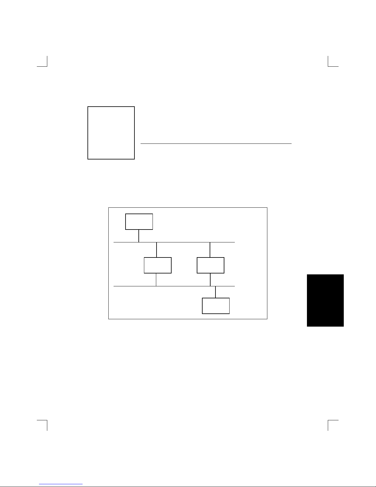
The LSB4 is designed to be connected to an Ethernet; it will divide the
Ethernet into 4 network segments. The LSB4 will isolate each segmentÕs local packet traffic; in other words, packets that are not destined for another
segment of the network will not pass through the switch. This reduces unwanted packet traffic on other segments of the network.
Figure 1-1 illustrates the use of the LSB4.
Figure 1-1: LANs With and Without LSB4
LAN Without Switch LAN With Switch
Sun Sun MicroVAXMicroVAX
LSB4
Page 10

LSB4 Installation Guide Introduction
1-3
Introduction
Introduction
In the Local Area Network without a switch [Figure 1-1], incoming packets are examined by all hosts connected to the network. In the Local Area
Network with the LSB4 installed, the only traffic on the Sun segment of the
switch will be between the Suns plus any traffic specifically directed to a
VAX or directed to a Sun from a VAX. The same applies to the VAX segment of the network.
Management of Packet Traffic
The LSB4 does not add or change any of the information in the packets that
passes through the switch. However, it can be configured to regulate the
passage of certain packet traffic through the use of filters . Filters prevent
the passage of particular packets from one segment to another.
For more information about filters, see the Filter Commands chapter of
the LSB4 Reference Manual.
Initial LSB4 Configuration
When the switch boots up, it will be configured in the following manner:
♦
Automatic filtering and forwarding of packets will
take place. To customize packet filtering, see the Filter
Commands chapter of the LSB4 Reference Manual.
♦
The Spanning Tree Algorithm will be enabled. This
can be disabled or customized to particular needs; see
Appendix B, Spanning Tree Algorithm for more information.
To view diagnostic information as the LSB4 boots up, a terminal must be
connected to the LSB4. A serial cable is shipped with the switch; this may
be used to connect a terminal to the serial console port.
NOTE
Page 11

Introduction LSB4 Installation Guide
1-4
Introduction
Networks and Protocols Supported
The LSB4 supports and processes packets for any Ethernet network. The
operation of the LSB4 is fully compliant with both the IEEE 802.3 Ethernet
specification and the IEEE 802.1d Bridge specification.
The LSB4 operates independently of the different protocols used in packets. Unless a particular protocol is specified using the Set/Define Filter
command, the bridge will pay no attention to a packet's protocol.
Remote connections can be made through one of the LAN ports using any
of the following protocols: AppleTalk, NetWare, Telnet/Rlogin, or MOP/
NCP/TSM. (The protocols may be disabled in order to improve performance.) In addition to the protocols listed above, the LSB4 responds to
pings and SNMP commands.
See Chapter 3, Set-up and Operation, for more information about logging into the LSB4 through the network.
NOTE
Page 12

LSB4 Installation Guide Introduction
1-5
Introduction
Introduction
LSB4 vs. Other Methods
A switch differs significantly from other methods of connecting Ethernet
segments together. A few examples of segment connection and the ways
in which they differ from a network switch are discussed in Table 1-1.
Table 1-1: Comparisons to Network Switch
Method of
Segment
Connection
Comparison to Network Switch
Connecting directly to
the local area
network (using a ÒTÓ
or barrel connector)
An Ethernet has maximum cable lengths and maximum numbers of devices that can be connected. With
a switch installed, each segment connected by the
switch may use the maximum amount of cable length
and maximum number of connected devices.
Connecting segments
with a repeater
A repeater forwards all network traffic, including
problems such as collisions. Rather than automatically forwarding all traffic, a switch forwards only packets intended for that particular Ethernet segment.
Nodes no longer receive unwanted traffic; this reduces network traffic on all segments.
Connecting segments
with a router
A router must be configured for the different protocols being used on the network. A switch is unaffected by the nature or contents of the data in the packets
it receives; it requires no information about the different protocols being used on the network.
Page 13

Introduction LSB4 Installation Guide
1-6
Introduction
Page 14

2
Installation
Installation
Installation Instructions.............................................................................2-1
Initializing the LSB4................................................................................... 2-4
Initial LSB4 Configuration ........................................................................2-6
Changing System Passwords.................................................................... 2-7
IP Address Configuration .........................................................................2-8
Power-up Troubleshooting..................................................................... 2-10
Page 15

LSB4 Installation Guide Installation
2-1
Introduction
Installation
Installation Instructions
To connect the LSB4 to your Local Area Network, complete the following
steps:
♦
Connect one or all of the LSB4's network ports to an Attachment Unit Interface (AUI) cable or to a transceiver.
♦
Connect a terminal to the LSB4's serial console port (optional.) The port is configured at the factory for 9600
baud, 8 data bits, no parity, and one stop bit.
♦
Plug the power cord into the AC input on the LSB4 and
into an AC power source.
See Figure 2-1 on page 2-2 for an illustration of the LSB4.
For connector specifications and configuration, see the LSB4 Reference
Manual.
The LSB4 is configured at the factory to operate in any network configuration. For specific configuration instructions, see Chapter 3, Set-up and Op-
eration .
NOTE
2chapternumber
Page 16

Installation LSB4 Installation Guide
2-2
Installation
Figure 2-1: LSB4 Back and Front Panels
The illustrations on the following page [Figure 2-2 and Figure 2-3] are examples of the placement and connection of the LSB4 to different types of
networks.
LAN Ports
Serial Console Port
AC input
AUI 3 Address::
#
AUI 4 Address:
#
Serial
95-250V ~ 50-60Hz 0.5A T2A/250V
CAUTION
For continued protection against
risk of fire, replace only with
same type and ratings of fuse
Made in U.S.A.
Fabriqué in Etats-Unis
This equipment complies with Part 15 of the FCC Rules. Operation is subject to the following
two conditions: (1) the device may not cause harmful interference, and (2) this device
must accept any interference received, including interference that may cause undesired
operation.
Serial #
LSB4
SER 2 1
LANTRONIX
LSB4
AUI 1 Address::
#
AUI 2 Address:
#
34
Page 17

LSB4 Installation Guide Installation
2-3
Introduction
Installation
Figure 2-2: Network Configuration Example ( Thickwire )
Figure 2-3: Network Configuration Example ( Thinwire/10BASE-T )
Thickwire
10BaseT Hub
Twisted Pair
Macintosh
Netware
File Server
Sun
MicroVAX
10Base2
Repeater
Thinwire
Macintosh
Sun
MicroVAX
LSB4
10BaseT Hub
Macintosh
Netware
File Server
Sun
MicroVAX
Macintosh
Thinwire
10Base2
Repeater
MicroVAX
Netware
File Server
LTX-TA
Transceivers
LSB4
LTX-2A
Page 18

Installation LSB4 Installation Guide
2-4
Installation
Initializing the LSB4
Each time the LSB4 is turned on, it will go through an initialization process. The process consists of the following steps:
♦
Power-on diagnostic tests will last approximately 5
seconds.
♦
The contents of the LSB4's internal Flash ROM will be
checked for validity and then executed. This will take
approximately thirty seconds.
The LEDs will display as follows:
♦ During power-up diagnostics, the serial and network
port LEDs will display varying patterns depending on
the test being run. If the unit fails power-up diagnostics, it will display a fixed pattern.
If the LEDs display a fixed pattern, contact Lantronix technical support
for additional information.
♦ If the unit passes its power-up diagnostics, all serial
and network port LEDs will show green for three seconds.
♦ When the LSB4 is operational, the serial LED will be
green and blink every second, or more often if the serial console port is being used. The Network Port
LEDs will blink roughly in accordance with the traffic
on the network ports. If there is no activity on a particular port, its LED will remain off. If there is no transceiver connected to a port or the port has a faulty
network connection, the Network Port LED will be
solid orange.
NOTE
Page 19

LSB4 Installation Guide Installation
2-5
Introduction
Installation
If there is a problem during the initialization process, the serial LED will
be orange after individualization is complete. If this occurs, see ÒPowerup TroubleshootingÓ on page 2-10.
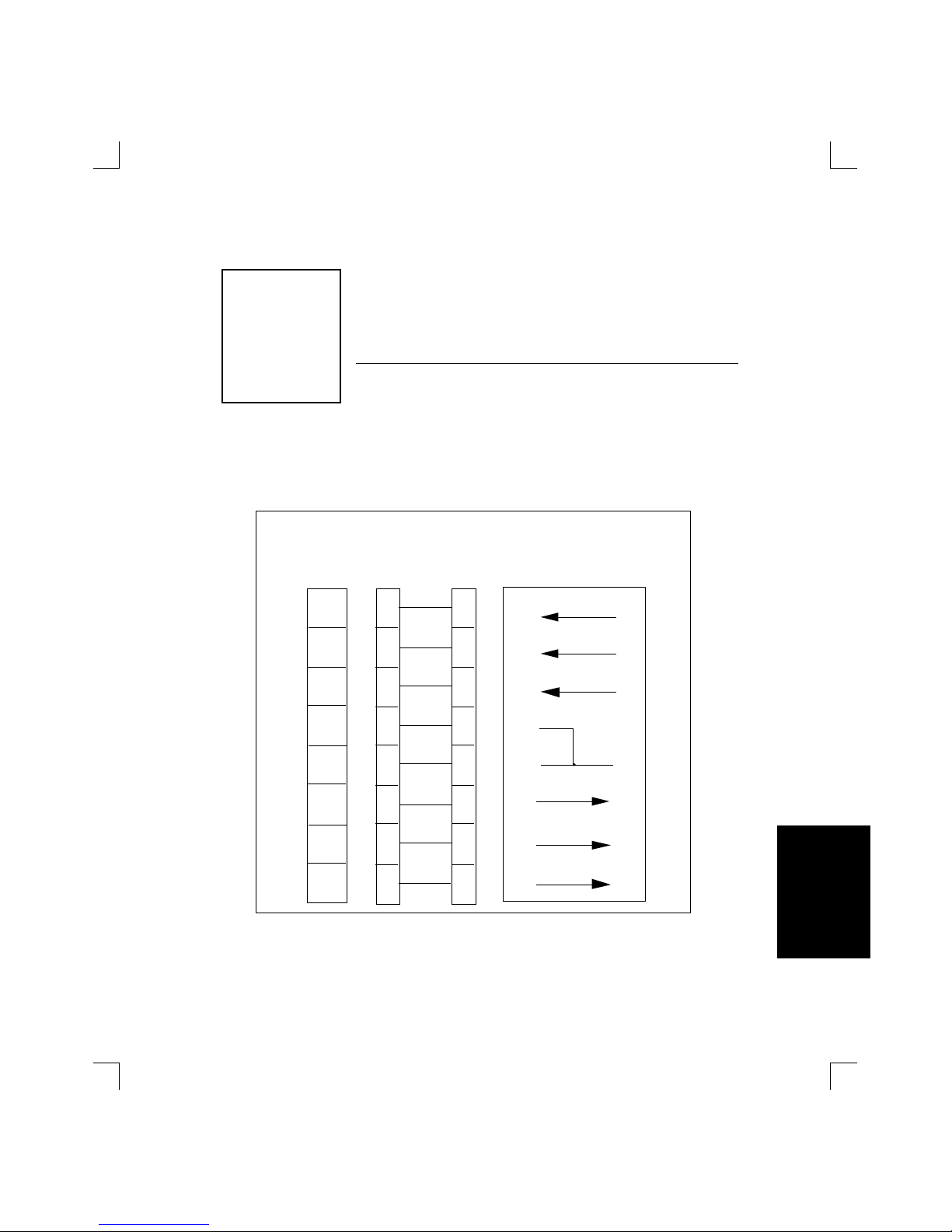
If a terminal is attached to the serial console port, text similar to the following will be displayed on the terminal during initialization [Figure 2-4].
Figure 2-4: Startup Messages
When all of the above is complete, the LSB4 is running normally.
Lantronix LSB4 Initialization
Boot Rom Version
n.n (Month Day, Year
)
Port 1: Ethernet Address: 00-80-A3-xx-xx-xx
Port 2: Ethernet Address: 00-80-A3-xx-xx-xx
Internet Address: (undefined)
Current Diagnostics Report:
RISC: 3051 (4K I/2K D) CPU Speed: 20 MHz
RAM Size: 1 MB Flash Size: 512 K
Flash Version:
n.n
Gate Array Rev:
n.n
Errors: None
Checking 8 sections from flash:
From address 0x
nnn
to 0x
nnn, nnn
bytes) -> ....
From address 0x
nnn
to 0x
nnn, nnn
bytes) ->
From address 0x
nnn
to 0x
nnn, nnn
bytes) -> ....
From address 0x
nnn
to 0x
nnn, nnn
bytes) -> ....
From address 0x
nnn
to 0x
nnn, nnn
bytes) ->
From address 0x
nnn
to 0x
nnn, nnn
bytes) -> ....
From address 0x
nnn
to 0x
nnn, nnn
bytes) -> ....
From address 0x
nnn
to 0x
nnn, nnn
bytes) ->
Loaded
nnnnnn
bytes.
Load Completed - Boot in Progress
%% Lantronix LSB4
%% Ethernet 1 Address: 00-80-A3-
xx-xx-xx
Internet Address: (Undefi
n
%% Ethernet 2 Address: 00-80-A3-
xx-xx-xx
Port 3: Ethernet Address: 00-80-A3-xx-xx-xx
Port 4: Ethernet Address: 00-80-A3-xx-xx-xx
%% Ethernet 3 Address: 00-80-A3-
xx-xx-xx
%% Ethernet 4 Address: 00-80-A3-
xx-xx-xx
NOTE
Page 20

Installation LSB4 Installation Guide
2-6
Installation
If the messages on the previous page do not appear on the terminal, see
Power-up Troubleshooting on page 2-10.
If the characters displayed on the terminal are incoherent, turn the LSB4
off, check the settings on the terminal, the cable connections, and turn the
LSB4 on again.
Initial LSB4 Configuration
The LSB4 will operate properly in all local area networks without the need
for any configuration changes. After the power-up initialization process,
the LSB4 will automatically start learning the different node addresses
connected to its ethernet ports and will start to process traffic within approximately one minute of power-up.
The LSB4 can be configured further, for example, to filter certain packet
traffic, or to enable logins from other network nodes. Configuration is
done through the use of specific commands. There are several ways to enter these commands:
♦ Connect a terminal to the LSB4's serial console port
♦ Log onto the LSB4 over the network using one of the net-
work protocols: AppleTalk, NetWare, NCP/MOP/TSM,
Telnet/Rlogin
♦ Use BOOTP or ARP to configure the IP address from a
TCP/IP network host
♦ Send SNMP commands from an SNMP manager
Instructions for configuring the LSB4 will be provided in Chapter 3, Setup and Operation.
NOTE
NOTE
Page 21

LSB4 Installation Guide Installation
2-7
Introduction
Installation
Changing System Passwords
There are two important passwords on the LSB4: the privileged password
and the login password.
The privileged password is the password that must be entered to become
the privileged user. The default privileged password is system; it can be
changed with either the Set System Privileged Password or Define Sys-
tem Privileged Password command.
The privileged user level is required before the privileged password can
be changed. Use the default privileged password to obtain the privileged
user level.
The login password is required for logging into the LSB4 through a network connection. The default login password is access; it can be changed
with either the Set System Login Password or Define System Login Pass-
word command.
To begin using the terminal connected to the serial console port, press
Return until a user prompt appears.
Use of the Set/Define System Privileged Password and Set/Define System
Login Password are shown in Figure 2-5.
Figure 2-5: Set/Define Password Commands
Local> SET PRIVILEGED
Password> SYSTEM (not echoed)
Local>> SET SYSTEM PRIVILEGED PASSWORD HOBBES
Local>> DEFINE SYSTEM PRIVILEGED PASSWORD HOBBES
Local>> SET SYSTEM LOGIN PASSWORD CALVIN
Local>> DEFINE SYSTEM LOGIN PASSWORD CALVIN
NOTE
NOTE
Page 22

Installation LSB4 Installation Guide
2-8
Installation
IP Address Configuration
The LSB4's IP address must be configured before any TCP/IP functionality is available. The address can be defined using a terminal connected to
the serial port, or via a host BOOTP or RARP server.
To define the IP address via the serial port, connect a terminal to the LSB4,
become the privileged user and issue the Set and Define Protocol IP IP-
address commands [Figure 2-6].
Figure 2-6: Set/Define Protocol IP Commands
To configure the IP address using RARP or BOOTP, see the
RARP/BOOTP server's documentation.
Many BOOTP daemons will not reply to a BOOTP request if the download filename in the configuration file does not exist. If this is the case,
create a file in the download path to get the BOOTP daemon to respond.
To configure the IP address using ARP, create an entry in the hostÕs ARP
table [Figure 2-7]. Note that this requires privileged user status.
Figure 2-7: Creating ARP Entry
Local> SET PRIVILEGED
Password> SYSTEM (not echoed)
Local>> SET PROTOCOL IP IPADDRESS xxx.xxx.xxx.xxx
Local>> DEFINE PROTOCOL IP IPADDRESS xxx.xxx.xxx.xxx
# arp -s 192.0.1.228 00:80:a3:xx:xx:xx
NOTE
Page 23

LSB4 Installation Guide Installation
2-9
Introduction
Installation
Substitute the intended IP address and the hardware address of the
switch. Then ping the switch using the following command [Figure 2-8]:
Figure 2-8: Ping Command
When the switch receives the ping packet, it will notice that its IP address
is currently not set and will send out broadcasts to see if anyone else is using this address. If no duplicates are found, the switch will use this IP address and will respond to the ping packet. The LSB4 will not save this
learned IP address permanently. It is intended as a temporary measure to
enable the administrator to telnet into the LSB4Õs console port.
Any host wishing to access the LSB4 will have to be told of the LSB4's IP
address. This is typically configured in the file /etc/hosts or via a nameserver. Refer to the host's documentation for additional information.
unix% ping xxx.xxx.xxx.xxx
Page 24

Installation LSB4 Installation Guide
2-10
Installation
Power-up Troubleshooting
There are several possible error situations if the terminal connected to the
serial port does not display the welcome message or the LEDs on the LSB4
do not light properly.
Condition: All serial and network port LEDs display a specific pattern denot-
ing the exact failure. A terminal connected to the serial console
port may also display an error message. The LSB4 is unable to proceed further.
Cause: The LSB4 has detected a fatal hardware fault.
Action: Contact your hardware dealer or Lantronix.
Condition: An error is detected during power-up that is non-fatal; the LSB4
continues to boot up but will not begin normal operation. The serial LED will blink orange. If a terminal is connected to the serial
console port, a diagnostic message is displayed. The terminal displays a Boot> prompt and awaits a response.
Cause: The LSB4 has detected network errors on one or all of the ethernet
ports.
Action: Connect a terminal to the serial console port if one is not connect-
ed. Check the network connection, and verify that power is reaching the MAUs.
Page 25

LSB4 Installation Guide Installation
2-11
Introduction
Installation
Condition: All tests have passed successfully but the instructions stored in
Flash ROM have become corrupted. The LSB4 will automatically
attempt to find and load a file containing instructions from a host
on the local area network. All of the Network Port LEDs will be alternating as the LSB4 looks for new software.
The following text will be displayed on the terminal connected to
the serial console port [Figure 2-9]:
Figure 2-9: LSB4 Searching For Instruction File
If the last line in the above message appears, the LSB4 has been
unable to find and load the instruction file.
Cause: Usually this occurs if the LSB4 is disturbed while downloading a
file containing instructions for the LSB4's Flash ROM. The stored
instructions become corrupted.
Action: Reload the file containing the Flash ROM instructions.
See Appendix E, Updating LSB4 Software for instructions on reloading
Flash-ROM.
Checking X sections from flash: invalid checksum
found.
Attempting TFTP boot....
Attempting NetWare boot.....
Attempting MOP boot....
Will wait 1 minute for next download attempt...
NOTE
Page 26

Installation LSB4 Installation Guide
2-12
Installation
Condition: All tests have passed and the unit is operating normally, but it ap-
pears that no packet traffic is being forwarded by the LSB4 to the
different segments of the local area network.
Cause: There are several conditions that can cause this problem. Often it
is caused by incorrect or faulty network cable connections or incorrect network hardware configuration.
Action: Check the LEDs of the LAN ports to see if they are green and
flashing, and use the Show Switch Status command to determine
the state of the ports.
Where Show /Monitor /List Switch and Set/Define Switch commands are used, ÒBridgeÓ can be used in place of ÒSwitch.Ó For example,
List Bridge has the same functionality as List Switch.
♦ If Show Switch Status displays that a port is in the
testing state, there is a faulty network connection.
Check the cable connections.
♦ If Show Switch Status displays that a port is in the
overflow state, there may be a ÒloopÓ in the network due to the Spanning Tree Algorithm being
disabled. Ensure that the switch state and span-
ning tree are enabled; these parameters can be set
with the Set/Define Switch command.
If conditions occur that havenÕt been described in this section, contact
Lantronix Technical Support. For contact information, refer to Appendix A.
NOTE
NOTE
Page 27

3
Set-up and Operation
Installation
Set-up and
Operation
Accessing the LSB4 .................................................................................... 3-1
Connections from TCP/IP Hosts .............................................. 3-2
Connections from VMS Hosts ................................................... 3-6
Connections from Netware Hosts............................................. 3-7
Connections from Macintosh Hosts using AppleTalk........... 3-9
Editing Command Entries ........................................................................ 3-9
Editing Keys ................................................................................. 3-9
Automatic Command Completion ......................................... 3-11
Common Configuration Changes.......................................................... 3-12
Password Protection.................................................................. 3-12
System Configuration ............................................................... 3-13
Customizing Serial Console Port Settings.............................. 3-15
Switch Configuration ................................................................ 3-16
Filter Configuration................................................................... 3-18
Page 28

3
Set-up and Operation
Installation
Set-up and
Operation
Page 29

LSB4 Installation Guide Set-up and Operation
3-1
Introduction
Set-up and
Operation
Accessing the LSB4
There are two ways to issue commands to the LSB4: through a terminal
connected to the serial console port, or through a console somewhere on
the local area network.
Connecting a terminal to the serial console port is discussed in Chapter 2,
Installation. To start using the terminal after it is physically connected,
press Return until a user prompt appears.
How the LSB4 is accessed through one of the LSB4's ethernet ports will depend on the requirements of the network host. There are several different
host types:
♦ TCP/IP
♦ VAX/VMS
♦ NetWare
♦ AppleTalk
Each host type listed above requires a somewhat different approach when
connecting over the network to the LSB4.
Remote logins via each supported protocol are enabled by default.
NOTE
3chapternumber
Page 30

Set-up and Operation LSB4 Installation Guide
3-2
Introduction
Set-up and
Operation
Connections from TCP/IP Hosts
Connecting to the LSB4 from a TCP/IP host consists of two steps: obtaining an IP address, and logging into the LSB4.
Obtaining an IP Address
An IP address is required in order to log into the LSB4 from a TCP/IP host.
The address can be defined using a terminal connected to the serial console port, or via a BOOTP or RARP host.
Contact your network administrator to obtain an IP address.
To define the IP address via the serial port, connect a terminal to the LSB4,
become the privileged user and issue the Set and Define Protocol IP IP-
Address commands [Figure 3-1].
The Set command configures something now, but is not permanent. De-
fine changes a setting permanently, but does not take effect until the
LSB4 is rebooted or initialized. For more information on Set and Define
commands, refer to the LSB4 Reference Manual.
Please note that Figure 3-1 displays the default privileged password; this
password will not be valid if the privileged password has been changed.
Figure 3-1: Set/Define Protocol IP Commands
Local> SET PRIVILEGED
Password> SYSTEM (not echoed)
Local>> SET PROTOCOL IP IPADDRESS xxx.xxx.xxx.xxx
Local>> DEFINE PROTOCOL IP IPADDRESS xxx.xxx.xxx.xxx
NOTE
NOTE
Page 31

LSB4 Installation Guide Set-up and Operation
3-3
Introduction
Set-up and
Operation
To configure the IP address using RARP or BOOTP, refer to the
RARP/BOOTP host documentation.
Many BOOTP daemons will not reply to a BOOTP request if the download filename in the configuration file does not exist. If this is the case,
create a file in the download path to get the BOOTP daemon to respond.
If the LSB4 has no IP address, it will set its address from the first directed
IP address it receives. To generate such a packet, create an entry in the
hostÕs ARP table [Figure 3-2]. Note that this requires that privileged user
status.
Figure 3-2: Creating ARP Entry
Substitute the intended IP address and the hardware address of the
switch. Then ping the switch using the following command [Figure 3-3]:
Figure 3-3: Ping Command
When the switch receives the ping packet, it will notice that its IP address
is currently not set and will send out broadcasts to see if anyone else is using this address. If no duplicates are found, the switch will use this IP address and will respond to the ping packet. The LSB4 will not save this
learned IP address permanently. It is intended as a temporary measure to
enable the administrator to telnet into the LSB4Õs console port.
Any host wishing to access the LSB4 will have to be given the LSB4's IP address. This is typically configured in the file /etc/hosts or can be obtained
via a nameserver. Refer to the host's documentation for additional information.
# arp -s 192.0.1.228 00:80:a3:xx:xx:xx
unix% ping xxx.xxx.xxx.xxx
NOTE
Page 32

Set-up and Operation LSB4 Installation Guide
3-4
Introduction
Set-up and
Operation
Logging into the LSB4
At the prompt type one of the following [Figure 3-4]:
Figure 3-4: Login Commands
where nnn.nnn.nnn.nnn is the IP address of the LSB4. nnn is a decimal
number from 0 to 255.
The following text will be displayed [Figure 3-5]:
Figure 3-5: Text Displayed Before Login
At the # prompt, type the login password. The password will not be displayed.
The default login password is access. This password can be changed using the Set/Define System Login Password command.
The following text will be displayed [Figure 3-6]:
Figure 3-6: Text Displayed Upon Login
unix% telnet nnn.nnn.nnn.nnn
unix% rlogin nnn.nnn.nnn.nnn
Trying nnn.nnn.nnn.nnn
Connected to nnn.nnn.nnn.nnn
Escape character is ‘^]’
Lantronix LSB4 Version
n.n/n(yymmdd)
Type Help at the ‘Local>’ prompt for assistance.
Username>
NOTE
Page 33

LSB4 Installation Guide Set-up and Operation
3-5
Introduction
Set-up and
Operation
Type a username at the prompt and press the Return key. The LSB4 can
then be configured as if at a terminal connected to the serial console port.
The session can be ended by typing Ctrl-D or logout.
Any privileged user can prevent TCP/IP host logins by entering the Set/
Define System Incoming None command. Port 7000 (see Console
Connections on page 3-5) and existing logins will not be affected. For
more information on this command, see the System Commands chapter
of the LSB4 Reference Manual.
Console Connections
The LSB4 enables a TCP/IP user to configure the server via a single telnet
connection to the remote console port. The remote console port is designate as port 7000. To make a connection to this port, use the telnet command [Figure 3-7].
Figure 3-7: Connecting to Console Port
Note that the # prompt requires that the login password be entered before
the connection can be made. The default login password is access. This
password can be changed with the Set System Login Password command.
See the LSB4 Reference Manual for details on this command.
% telnet xxx.xxx.xxx.xxx 7000
Trying xxx.xxx.xxx.xxx
Connected to xxx.xxx.xxx.xxx
Escape character is ‘^]’
# access (not echoed)
Lantronix LSB4 Version n.n/n (yymmddd)
Type Help at the ‘Local_4>’ prompt for assistance.
Enter Username> xxxx
NOTE
Page 34

Set-up and Operation LSB4 Installation Guide
3-6
Introduction
Set-up and
Operation
Connections from VMS Hosts
To access the LSB4 using a VMS network host, type the following
[Figure 3-8]:
Figure 3-8: VMS Connect Commands
LSB4name represents the name of the LSB4 as identified in the NCP ad-
dress database.
See your NCP documentation for information about the address database.
At the # prompt, type the login password. The password will not be displayed.
The default login password is access. This password can be changed using the Set/Define System Login Password command.
The following will be displayed [Figure 3-9]:
Figure 3-9: Text Displayed Before Login
Type a username at the prompt and press the Return key. The LSB4 can
then be configured as if at a terminal connected to the serial console port.
The session can be ended by typing Ctrl-D or logout.
$ RUN SYS$SYSTEM:NCP
NCP> CONNECT NODE
LSB4name
#
Lantronix LSB4 Version
n.n/n(yymmdd)
Type Help at the ‘Local>’ prompt for assistance.
Username>
NOTE
NOTE
Page 35

LSB4 Installation Guide Set-up and Operation
3-7
Introduction
Set-up and
Operation
Connections from Netware Hosts
For PC hosts using Netware, the BRCON utility program is provided with
the LSB4 on a DOS diskette. BRCON enables a PC host to log into or issue
commands to the LSB4.
To use the BRCON utility, a Netware file server connection must be
open, or the NetWare workstation shell program must be running.
Copy the BRCON utility program to the hard disk being used or insert the
LSB4 diskette into the A: drive and type the following command
[Figure 3-10]:
Figure 3-10: BRCON Command
A list of the parameters that can be used with the BRCON command will
be displayed [Figure 3-11].
Figure 3-11: BRCON Command List
LSB4name represents the LSB4 service name. The service name is LSB4_
(underscore), followed by the last three bytes of port 1Õs hardware address. For example, if the hardware address (listed above port 1 on the rear
of the unit) is 00-80-A3-08-02, the service name would be LSB4_A30802.
C:> BRCON
Brcon Ver. 1.5
------------------brcon list list available switches
brcon <LSB4
name
> establish a console connect
i
brcon <LSB4
name
> reload reload a switch
NOTE
Page 36

Set-up and Operation LSB4 Installation Guide
3-8
Introduction
Set-up and
Operation
Enter the following to log into the LSB4 [Figure 3-12]:
Figure 3-12: Login Command
The display will show [Figure 3-13]:
Figure 3-13: Login Prompt
At the # prompt, type the login password. The password will not be displayed.
The default login password is access. This password can be changed using the Set/Define System Login Password command.
The following will be displayed [Figure 3-14]:
Figure 3-14: Username Prompt
Type a username at the prompt and press the Return key. The LSB4 can
then be configured as if at a terminal connected to the serial console port.
To logout of the LSB4, press Ctrl-D or type logout.
C:\> BRCON LSB4_
xxxxxx
Connection established (Ctrl-break to terminate)
#
Lantronix LSB4 Version
n.n/n(yymmdd)
Type Help at the ‘Local>’ prompt for assistance.
Username>
NOTE
Page 37

LSB4 Installation Guide Set-up and Operation
3-9
Introduction
Set-up and
Operation
Connections from Macintosh Hosts using AppleTalk
The MACCON utility program is supplied with the LSB4 on a Macintosh
diskette. MACCON enables a Macintosh using AppleTalk to log into or issue commands to the LSB4.
To install MACCON, copy it onto a hard disk drive or run it directly from
the diskette. Double click on the MACCON icon to launch the program.
The screen will display AppleTalk zones and known Lantronix devices
connected to the network.
Clicking on any AppleTalk zone name will display the devices in that
zone. Double-click on any node name to log into that node, or enter configuration commands. Click the Quit button to exit MACCON.
Editing Command Entries
The LSB4 offers two features to assist you when entering commands: editing keys, and automatic command completion.
These features are not available in boot mode.
Editing Keys
Table 3-1 on page 3-10 lists the special keys used for command line editing.
NOTE
Page 38

Set-up and Operation LSB4 Installation Guide
3-10
Introduction
Set-up and
Operation
Table 3-1: Command Line Editing Keys
Key Purpose
Return Executes the command line
Delete Deletes the character immediately left of the cursor
Ctrl-A Toggles insert mode (insert or overwrite)
Ctrl-D or Ctrl-Z Logs out of the switch
Ctrl-E Moves the cursor to the end of the line
Ctrl-H or Backspace Moves the cursor to the beginning of the line
Ctrl-R Displays the current command
Ctrl-U Deletes the entire current line
Right Arrow Moves the cursor to the right
Left Arrow Moves the cursor to the left
Up Arrow or Ctrl-P Recalls the previous command
Down Arrow or Ctrl-N When scrolling through previously-entered com-
mands, displays the next command entered
!!Return Executes the previously entered command
!textReturn Recalls the last command starting with text
Page 39

LSB4 Installation Guide Set-up and Operation
3-11
Introduction
Set-up and
Operation
Automatic Command Completion
The LSB4 supports two types of automatic command completion: command recall, and partial command completion.
Command Recall
Pressing the Up Arrow and Down Arrow keys displays previously-entered commands at the input prompt. This feature is called command re-
call. The Up Arrow key scrolls backward through the previously-entered
commands, and the Down Arrow key scrolls forward.
Once recalled, the command can be executed again, or edited and then executed. Up to nine previous commands can be scrolled through. If no commands have previously been entered, a blank line will be displayed when
the Up Arrow or Down Arrow keys are pressed.
In addition to command recall, the LSB4 supports the UNIX command
history list feature, which is activated by typing exclamation ( ! ) marks.
Entering two exclamation marks (!!) executes the previous command. Typing a single exclamation mark and one or more text characters will search
for and display the previous command starting with the text characters.
Partial Command Completion
Partial command completion completes a partially-typed command when
the Space Bar or Tab key is pressed. If the LSB4 cannot determine the remainder of a partially-typed command, it will beep and wait for user in
put.
For example, if the following is entered [Figure 3-15]:
Figure 3-15: Partially-typed Command
and the space bar or the Tab key is pressed, the word filter will appear at
the prompt.
Local> SET FI
Page 40

Set-up and Operation LSB4 Installation Guide
3-12
Introduction
Set-up and
Operation
Partial command completion can be enabled or disabled; see Set/Define
Port Command Completion in Chapter 4 of the LSB4 Reference Man-
ual.
Common Configuration Changes
As stated in Chapter 2, the LSB4 does not require additional configuration
to operate properly in a local area network. Customization of the LSB4 is
optional, and includes the following:
♦ Password protection
♦ System configuration
♦ Serial console port characteristics
♦ Switch configuration
♦ Filter configuration
This section does not cover all configuration options; for a complete discussion of LSB4 configuration and commands, refer to the LSB4 Reference Manual.
Password Protection
The LSB4 is protected with two levels of passwords: the login password
and the privileged password. Using and changing these passwords is described in Changing System Passwords on page 2-7.
NOTE
NOTE
Page 41

LSB4 Installation Guide Set-up and Operation
3-13
Introduction
Set-up and
Operation
System Configuration
Three of the system configuration options are: modification of the system
name, restriction of incoming network logins, and specification of the
AppleTalk zone.
System Name
The system name is used by NetWare and AppleTalk networks to remotely access the LSB4.
The LSB4 will be identified as LSB4_xxxxxx. The xÕs represent the last six
digits of the switchÕs ethernet address. The switch name can be changed
using the Set/Define System Name command, shown in Figure 3-16.
Privileged access must be obtained before the Set/Define System Name
command can be used. Use the Set Privileged command (displayed in
the following example) to obtain privileged status.
Figure 3-16: Changing Switch Name
Incoming Network Logins
By default, the LSB4 will prevent all incoming network logins, with the exception of remote console logins using Telnet NCP/TSM connections. To
prevent all network logins, use the Set/Define System Incoming None
command [Figure 3-17, page 3-13].
Figure 3-17: Preventing All Network Logins
Local> SET PRIVILEGED
Password> SYSTEM (not echoed)
Local>> SET SYSTEM NAME
LAB_SWITCH
Local>> DEFINE SYSTEM NAME
LAB_SWITCH
Local>> SET SYSTEM INCOMING NONE
Local>> DEFINE SYSTEM INCOMING NONE
NOTE
Page 42

Set-up and Operation LSB4 Installation Guide
3-14
Introduction
Set-up and
Operation
For more information on the Set/Define System Incoming None command, see Chapter 2 of the LSB4 Reference Manual.
AppleTalk Zone
If the LSB4 is connected to an AppleTalk network that includes a router,
the LSB4 will join the default zone specified by the router. In this case, the
LSB4 and other Macintosh devices in the same zone will be seen by each
other. Devices outside the zone will not be visible.
If the LSB4 is connected to an AppleTalk network without a router, zones
will not be configured and all devices on the network (including the LSB4)
will be visible and accessible to all other Macintosh clients.
A different AppleTalk zone may be specified by entering a Set/Define
Protocol AppleTalk Zone command [Figure 3-18]:
Figure 3-18: Specifying AppleTalk Zone
The MACCON utility program and the specified zone are of consequence
only when connecting to the LSB4 through the AppleTalk network.
Local> SET PRIVILEGED
Password> SYSTEM (not echoed)
Local>> SET PROTOCOL APPLETALK ZONE RADON_LAB
Local>> DEFINE PROTOCOL APPLETALK ZONE RADON_LAB
NOTE
NOTE
Page 43

LSB4 Installation Guide Set-up and Operation
3-15
Introduction
Set-up and
Operation
Customizing Serial Console Port Settings
The default characteristics of the serial console port are listed in
Figure 3-19.
Figure 3-19: Serial Port Default Characteristics
These settings can be changed using the Set Port and Define Port commands. Some examples of Set/Define Port commands are shown below
[Figure 3-20]:
Figure 3-20: Set/Define Port Examples
To make Set Port commands permanent, use the Save Port or the Define
Port command.
For information about the Save command, refer to the LSB4 Reference
Manual.
Local> LIST PORT
Port 1: Username: Physical Port 1 (Idle)
Char Size/Stop Bits: 8/1
Input Speed: 9600
Flow Ctrl: Xon/Xoff
Output Speed: 9600
Parity: None
Modem Control: None
Terminal Type: Soft
Characteristics:
Local> SET PORT SPEED 38400
Local> SET PORT FLOW XON
Local> SET PORT COMMAND ENABLED
NOTE
Page 44

Set-up and Operation LSB4 Installation Guide
3-16
Introduction
Set-up and
Operation
The LSB4 doesn't need to be rebooted in order for Define Port commands
to take effect; they will take effect as soon as the port is logged out or finishes a print job.
When the port characteristics are changed, the terminal characteristics
may have to be changed to match.
Switch Configuration
The Set Switch and Define Switch commands can be used to configure two
areas of the LSB4: LAN port characteristics, and Spanning Tree Algorithm
specifications. Table 3-2 on page 3-17 describes the available Set/Define
Switch commands.
The Spanning Tree Algorithm is enabled by default, but can be completely disabled if necessary. For a more detailed explanation of the Spanning
Tree Algorithm, see Appendix B.
NOTE
NOTE
Page 45

LSB4 Installation Guide Set-up and Operation
3-17
Introduction
Set-up and
Operation
Table 3-2: Switch Configuration Commands
Command
Command
Type
Functionality
Set/Define Switch Forward Delay
delay
Spanning Tree Controls the delay interval be-
tween the LSB4Õs listening,
learning, and forwarding
states; is also the weed time
during topology changes
Set/Define Switch Hello Time time Spanning Tree Controls the interval between
Spanning Tree packet multicasts
Set/Define Switch Maximum Age
age
Spanning Tree Controls the time period that
the LSB4 will wait after the last
Spanning Tree packet before it
looks for a new root switch
Set/Define Switch Ethernet port
Path Cost value
Spanning Tree Controls how expensive a port
is in terms of packet forwarding time
Set/Define Switch Spanning Tree
Enabled/Disabled
Spanning Tree Enables or disables the Span-
ning Tree Algorithm
Set/Define Switch Weed weed Spanning Tree Controls the time period that
the LSB4 will wait before it removes a nodeÕs hardware address when it has not heard
from that node
Set/Define Switch Ethernet port
State Enabled/Disabled
Ethernet Port Will prevent packet traffic
through an ethernet port
Set/Define Switch Ethernet port
Priority value
Ethernet Port Assigns a value that will be
used to determine if the switch
will become the root switch
Set/Define Switch Ethernet port
Filter filtr
Ethernet Port Associates a filter list with one
of the LSB4Õs ethernet ports
Page 46

Set-up and Operation LSB4 Installation Guide
3-18
Introduction
Set-up and
Operation
Filter Configuration
When a packet is received at an LSB4 port, the source and destination addresses of the packet are compared. If the address of the source and destination of a packet are the same, the packet is presumed to be at its final
destination and doesn't need to travel any further. Once it is determined
that a packet is not at its destination (the source and destination addresses
do not match), a packet may then be subject to any existing filters.
Filters are used to permit or deny passage of data packets through the
LSB4. The Set Filter and Define Filter commands are used to specify filters. Related filter commands are Show/List Filters and Clear/Purge Fil-
ters.
Creating a “Firewall”
A firewall is often used to prevent all but one type of traffic (for example,
traffic from a specific node) from reaching a particular network segment.
When traffic destined for a specific segment reaches the LSB4, it will be
compared to a list of filters; if it is any but a specified type of traffic, it hits
a ÒfirewallÓ and goes no further--the packet is discarded.
The commands listed below [Figure 3-21] create a firewall between LAN
1 and any other network segment. Filter 1 is configured to deny access to
IP packets; this filter is assigned to port 1, preventing IP packets from traveling from port 1 to other segments.
Figure 3-21: Preventing IP Traffic Out of Port 1
Figure 3-21 included a Set Privileged command before the Set Filter
command. The Set Filter command requires privileged status; if privileged status is currently enabled, the Set Privileged command will not be
necessary.
Local_1> SET PRIVILEGED
Local_1> SYSTEM (not echoed)
Local_1>> SET FILTER 1 APPEND PROTOCOL IP DENY
Local_1>> SET SWITCH ETHERNET 1 FILTER 1
NOTE
Page 47

LSB4 Installation Guide Set-up and Operation
3-19
Introduction
Set-up and
Operation
The commands in Figure 3-22 prevent any IP traffic between LSB4 ports;
for example, IP packets from LAN 1 cannot reach LAN 2, and IP packets
from LAN 2 cannot reach LAN 4.
Figure 3-22: Preventing IP Traffic Between All Segments
The Set Switch command used above did not specify a particular ethernet
port to be used with filter 1, as a result, all LSB4 ports will deny IP traffic.
In the following example [Figure 3-23], only traffic from source hardware
address 00-80-a3-01-02-03 and source hardware address 00-80-a3-aa-bb-cc
will be forwarded by the LSB4. Nothing else will be forwarded, except for
multicast packets.
Figure 3-23: Only Permitting Specific Source Packets
An incoming packet is compared to the third filter (Òmulticast allowÓ)
only if its source address does not match the source addresses specified in
the first two filters. The fourth filter (Òall denyÓ) specifies that any packet
that is compared to the first three filters without matching them (has neither of the mentioned source addresses and is not a multicast packet) will
not be forwarded to any other segments.
The commands listed in this section are only a few examples of the use of
filters. For detailed information about filters and filter configuration, refer to the LSB4 Reference Manual.
Local> SET PRIVILEGED
Password> SYSTEM (not echoed)
Local_1>> SET FILTER 1 APPEND PROTOCOL IP DENY
Local_1>> SET SWITCH FILTER 1
Local_1> SET PRIVILEGED
Password> SYSTEM (not echoed)
Local_1>> SET FILTER 1 APPEND SOURCE 00-80-a3-01-02-03 AL
Local_1>> SET FILTER 1 APPEND SOURCE 00-80-a3-aa-bb-cc AL
Local_1>> SET FILTER 1 APPEND MULTICAST ALLOW
Local_1>> SET FILTER 1 APPEND ALL DENY
Local_1>> SET SWITCH FILTER 1
NOTE
Page 48

LSB4 Installation Guide Set-up and Operation
3-20
Introduction
Set-up and
Operation
Page 49

A-1
A
Technical Support
Installation
Technical
Support
If you are experiencing problems with the LSB4 or have suggestions for improving
the product, please contact Lantronix Technical support at the address or phone
number listed below. We are also reachable via Internet electronic mail; the address is support@lantronix.com.
LANTRONIX
15353 Barranca Parkway
Irvine, California 92718 USA
714-453-3990 ¥ FAX 714-453-3995 ¥ Toll Free 800-422-7044
When you report a problem, please provide the following information:
♦ Your name, and your company name, address, and phone number
♦ Lantronix model number
♦ Serial number of the unit
♦ Software version (use the Show System command to display)
♦ Network configuration, including the information from a Netstat com-
mand
♦ Description of the problem
♦ Debug report (stack dump) if applicable
♦ Status of the unit when the problem occurred (please try to include in-
formation on user and network activity at the time of the problem)
Aappnumber
Page 50

LSB4 Installation Guide Technical Support
A-2
Introduction
Technical
Support
Page 51
B-1
B
Spanning Tree Algorithm
Installation
Spanning Tree
Algorithm
Whenever two or more switches are connected to a local area network, the
possibility exists that more than one switch could connect the same segments. This could result in endless loops of packet traffic on the network
[Figure B-1].
Figure B-1: Multiple Paths Between Segments
The Spanning Tree Algorithm is a method used to sense the structure of
the network and prevent multiple paths between network segments. The
LSB4 uses the Spanning Tree Algorithm as defined by the IEEE specification 801.2d.
Host 1
Host 2
Switch 1 Switch 2
LAN A
LAN B
Bappnumber
Page 52

Spanning Tree Algorithm LSB4 Installation Guide
B-2
Spanning Tree
Algorithm
The Spanning Tree Algorithm looks at the network and, if it senses more
than one path from one segment to another, it will disable all except one
path [Figure B-2]. A disabled path may affect more than one port on more
than one switch.
Figure B-2: Network Using Spanning Tree Algorithm
Each disabled port will continue to listen to packet traffic, but will not forward any packets through the switch or transmit any packets out of the
disabled port. When multiple paths to the same segment have been identified, the path(s) with the highest path cost will be disabled.
The Spanning Tree Algorithm will respond to changes in network configuration. If an ethernet port has been disabled due to duplicate paths and
the single operational path becomes inoperable, a disabled ethernet port
will be re-enabled in order to recreate the path.
The Spanning Tree Algorithm is fully incorporated into the LSB4 and will
be enabled by default. To disable the algorithm, use the Set/Define Switch
Spanning command.
Host 1
Host 2
LSB4 LSB4
LAN A
LAN B
This LAN port is
now in the blocking
state -- it does not
transmit packets
Page 53

LSB4 Installation Guide Spanning Tree Algorithm
B-3
Introduction
Spanning Tree
Spanning Tree
Algorithm
Caution should be exercised when disabling the Spanning Tree Algorithm. If there are multiple paths, packets could be forwarded continuously, resulting in packet storms and node crashes. It is highly
recommended that all switches on a network enable the Spanning Tree
Algorithm. If one or more switches have the Spanning Tree Algorithm
disabled, care must be taken to avoid network loops.
The Spanning Tree Algorithm designates one of the switches as the
primary or root on the network. If there is only one switch, it is obviously
the root. If there is more than one, the hardware addresses and priority
factors will be used to select the root.
Once a root is chosen, it will send out packets called Bridge Protocol Data
Units (BPDUs) to each of its segments. Switches receiving the
BPDUs will send them to their other segment, propagating BPDUs
throughout the network.
Each switch throughout the network will then know from which ethernet
port it should be receiving Bridge Protocol Data Units. If a switch receives
one on a different port, it knows that there has been a change in the network configuration and it will re-establish a single path to each LAN segment. Conversely, if the switch stops hearing Bridge Protocol Data Units
completely, it will know a link has failed and a new path must be established.
If the root stops operating, a new root will be selected based on switch priority and hardware address.
NOTE
Page 54

Spanning Tree Algorithm LSB4 Installation Guide
B-4
Spanning Tree
Algorithm
When using the Spanning Tree Algorithm ethernet ports can be in one of
seven different conditions or states:
♦ Listening: An ethernet port will listen for multicast Bridge
Protocol Data Unit packets from other switches for
the interval specified by the Set/Define Switch
Forward Delay command. The switch starts in this
state when it is initialized.
♦ Learning: The switch will collect hardware address
information for its internal address table. The
learning state is entered when the listening
Forward Delay interval has expired; the LSB4 will
remain in the learning state for another Forward
Delay interval.
♦ Forwarding: The switch will forward packets from one segment
to another unless the port is blocked or disabled, or
there is a user-defined filter preventing the passage.
♦ Blocked: A port is prevented from passing packets from one
segment to another. This is brought about by the
Spanning Tree Algorithm (there are multiple paths
to the segment and forwarding a packet through
this port onto the segment will cause a loop.)
♦ Disabled: A port has been disabled with a Set/Define Switch
State command.
♦ Testing: The switch has detected an error in a particular
segment (for example, it is disconnected), and is
testing the segment to determine if the error has
been fixed.
♦ Overflow: There is no memory left on the switch to retrieve
incoming packets. This may occur if the Spanning
Tree Algorithm is disabled and there is a ÒloopÓ in
the network.
Page 55

LSB4 Installation Guide Spanning Tree Algorithm
B-5
Introduction
Spanning Tree
Spanning Tree
Algorithm
Particular events on the network can cause the switch to return to the Listening and Learning states. Selection of a new root is usually the event that
will cause this transition.
If the Spanning Tree Algorithm is disabled with a Set/Define Switch
Spanning command, the port state can only be Disabled, Forwarding,
Testing, or Overflow. The other three states are only reachable when the
Spanning Tree Algorithm is enabled.
NOTE
Page 56

LSB4 Installation Guide Spanning Tree Algorithm
B-6
Introduction
Spanning Tree
Spanning Tree
Algorithm
Page 57
C-1
C
Pinouts
Installation Pinouts
Figure C-1 shows the pinouts for wiring the LSB4 serial connector. Note
that these pinouts assume that the 8-conductor cable connecting the LSB4
and the Adapter block is a swapped cable.
Figure C-1: LSB4 Serial Connector Pinouts
1
2
3
4
5
6
DTR
RXD
SG
TXD
DSR
20
3
7
2
6
LSB4
RJ45
Cable
RJ45-DB25
Adaptor
RJ45 DB25
3
4
5
1
2
6
7
8
7
8
6
5
4
8
7
3
2
1
DTR
RX+
TX+
RX-
TX-
(out)
(out)
(in)
DSR
(in)
6
5
4
3
2
6
5
4
8
7
3
2
1
CTS
(in)
RTS
(out)
54CTS
RTS
Cappnumber
Page 58

Pinouts LSB4 Installation Guide
C-2
Pinouts
Figure C-2 shows how to wire the RJ45 to DB25 adapter.
Figure C-2: RJ45 to DB25 Adapter
A small square connector is provided with the LSB4 adapters. This connector is used to connect both transmit and receive grounds from the
RJ45 cable to the single signal ground on the DB25. The connector internally splices the two wires together and provides one wire into the DB25
connector. It is used as shown in Figure C-3 on the following page.
RJ45 pins 4&5
must both be
connected to
DB25 pin 7
RJ45/
Adapter Pinout
DB25 Connector
113
1425
12345678
248
135
7
6
12345678
Page 59

LSB4 Installation Guide Pinouts
C-3
Introduction
Spanning Tree
Pinouts
Figure C-3: Wire Splicer
To splice the wires, cut off the end of the wire that does not extend
through the connector and insert both wires into the connector. Make
sure that the wire that does not extend through the connector is in as far
as possible to ensure a solid connection. Carefully squeeze the connector
using a pair of pliers to ensure that it is fully latched.
Sealed at this end
DB25 Signal Ground (Pin 7)
RJ45 Tx Return (Pin 4)
RJ45 Rx Return (Pin 5)
Page 60

Pinouts LSB4 Installation Guide
C-4
Pinouts
RJ45 to DB9 (IBM PC Standard) Pinouts
To connect the LSB4 serial port to a DB9 connector using IBM PC standard pinouts, the following pinouts should be used [Figure C-4].
Figure C-4: IBM PC Standard Pinouts
1
2
3
4
5
6
DTR
RXD
SG
TXD
DSR
4
2
5
3
6
LSB4
RJ45
Cable
RJ45-DB9
Adaptor
RJ45
DB9
3
4
5
1
2
6
7
8
7
8
6
5
4
8
7
3
2
1
DTR
RX+
TX+
RX-
TX-
(out)
(out)
(in)
DSR
(in)
6
5
4
3
2
6
5
4
8
7
3
2
1
CTS
(in)
RTS
(out)
8
7
CTS
RTS
Page 61

LSB4 Installation Guide Pinouts
C-5
Introduction
Spanning Tree
Pinouts
Serial Cable Limits
Lantronix switches are RS-423 compliant, and are thus limited by the
equipment at the remote end of the serial line. If the LSB4 is connected
to an RS-232 device, it is subject to the RS-232 limits shown below. If connected to an RS-422 device, it is subject to the RS-422 limitations.
RS-232 lines are limited to 15m (50 ft) in length at 9600 baud. They will
generally work at longer lengths. RS-422 lines are limited to 300m (1000
ft).
Page 62

LSB4 Installation Guide Pinouts
C-6
Introduction
Spanning Tree
Pinouts
Page 63

D-1
D
SNMP Support
Installation
SNMP
Support
SNMP is an abbreviation for Single Network Management Protocol.
SNMP commands enable users (usually system administrators) to get information from and control other nodes on a local area network.
Information about SNMP can be obtained in RFCs (Request For Comments.) RFCs can be obtained via anonymous FTP from nisc.jvnc.net. To
obtain a specific RFC, use the pathname pub/RFC/ rfcnnn, where nnn is
the name of the desired RFC. To obtain the RFC index, use the pathname
pub/RFC/rfc-index.txt.
The LSB4 implements the Management Information Bases MIB-2 and
Bridge MIB. The MIBs and SNMP in general are documented in RFCs
1066, 1286, 1067, 1098, and 1213.
The LSB4 supports RFC 1286.
The LSB4 has the ability to access the facilities of the Management Information Base for SNMP command management on TCP/IP-based networks.
Dappnumber
NOTE
Page 64

SNMP Support LSB4 Installation Guide
D-2
SNMP
Support
The following SNMP object groups are supported:
system OBJECT IDENTIFIER ::= {mib-2 1}
interfaces OBJECT IDENTIFIER ::= {mib-2 2}
at OBJECT IDENTIFIER ::= {mib-2 3}
ip OBJECT IDENTIFIER ::= {mib-2 4}
icmp OBJECT IDENTIFIER ::= {mib-2 5}
tcp OBJECT IDENTIFIER ::= {mib-2 6}
udp OBJECT IDENTIFIER ::= {mib-2 7}
ethernet transmission OBJECT IDENTIFIER ::= {mib-2 10}
snmp OBJECT IDENTIFIER ::= {mib-2 11}
dot1dbridge OBJECT IDENTIFIER ::= {mib-2 17}
Page 65

E-1
E
Updating LSB4 Software
Updating
LSB4 Software
The latest version of the Lantronix LSB4 software and its associated release
note can obtained in three ways: from a diskette or other media (if, for example, a diskette was mailed from Lantronix), by downloading directly
from the Lantronix development systems through the Lantronix bulletin
board system (BBS), or by using anonymous ftp through the Internet. Using the Lantronix BBS and using anonymous ftp are discussed in Down-
loading from the Lantronix BBS on page E-10 and Obtaining Software via the
Internet on page E-12.
Questions or comments regarding the ftp or downloading processes can
be addressed via electronic mail: the Internet mailing address is
ftp@lantronix.com.
In addition to loading new software, this Appendix discusses reloading
current system software (if, for example, the LSB4 doesnÕt boot.) Current
LSB4 software can be reloaded from the LSB4Õs internal Flash ROM; this
procedure is discussed in Reloading Flash ROM on page E-2.
Eappnumber
Page 66

Updating LSB4 Software LSB4 Installation Guide
E-2
Updating
LB Software
Updating
LSB4 Software
Reloading Flash ROM
The LSB4 stores its software in Flash ROM. This software controls the initialization process, the operation of the LSB4, and the processing of commands. The contents of Flash ROM can be updated by downloading a new
version of the operational software.
The Flash ROM software is contained in a file called LSB.SYS, provided
with the LSB4 on a floppy diskette. This file must be accessible when updating Flash ROM.
Flash ROM can be updated using any of the following host protocols:
TCP/IP, VAX/VMS, or Netware. In addition, Boot Configuration Program (BCP) commands can be used.
Using TCP/IP Hosts
Updating the LSB4 using a TCP/IP host consists of two steps: making the
LSB.SYS file accessible on the host machine, and downloading the
LSB.SYS file from the host machine to the LSB4.
As stated in the previous section, the LSB.SYS file is shipped with the LSB4
on a DOS diskette. This diskette may be used to put the LSB.SYS file on the
host machine.
Downloading the LSB.SYS file from a TCP/IP host to the LSB4 is accomplished using the TFTP (Trivial File Transfer Protocol.) TFTP requires the
following: the LSB4Õs IP address, the host's IP address, and that the
LSB.SYS file name be identified.
If the TCP/IP host provides BOOTP support, BOOTP commands can be
used to identify the LSB4's name, IP address, hardware address, and the
pathname of the BOOTP information file. The pathname of the BOOTP
configuration file is usually /usr/etc/bootptab.
Page 67

LSB4 Installation Guide Updating LSB4 Software
E-3
Introduction
Updating
LB Software
Updating
LSB4 Software
To download the LSB.SYS file to the LSB4, enter the following commands
[Figure E-1]:
Figure E-1: Downloading LSB.SYS File
If the pathname contains lower-case characters, the name must be enclosed in quotation marks. There is an 32 character length limit for the path
name and a 16 character limit for the file name.
See the Set/Define System command in the LSB4 Reference Manual for
more details.
The Initialize Reload command will initialize the LSB4. As Set System
commands will be lost when this occurs, Define System commands should
be used (see the example above.) Use the List System command to check
the LSB4 settings before entering the Initialize Reload command.
The initialization process will take approximately one minute from the
time the Initialize command is entered. If the LSB.SYS file cannot be found
or accessed during initialization, the LSB4 will re-initialize using the current contents of the LSB4's Flash ROM.
As described in Chapter 2, the serial LED and LAN port LEDs will quickly
blink orange while the LSB4 is in boot mode (and reloading code), then
slowly blink green when the LSB4 returns to normal operational mode.
Local> SET PRIVILEGED
Password> SYSTEM (not echoed)
Local>> DEFINE PROTOCOL IP IPADDRESS
xxx.xxx.xxx.xxx
Local>> DEFINE SYSTEM SOFTWARE “/path/LSB.SYS”
Local>> DEFINE PROTOCOL IP LOADHOST
xxx.xxx.xxx.xxx
Local>> INITIALIZE RELOAD
NOTE
Page 68

Updating LSB4 Software LSB4 Installation Guide
E-4
Updating
LB Software
Updating
LSB4 Software
Using VAX/VMS Hosts
Updating the LSB4 using a VAX/VMS host consists of two steps: making
the LSB.SYS file available in the host machineÕs MOM$LOAD directory,
and downloading the LSB.SYS file from the host to the LSB4.
When the LSB.SYS file is to be loaded using MOP, the file name is the only
parameter required by the LSB4.
The LSB4's service characteristic must be enabled on the host's Ethernet
circuit. See the NCP documentation for more details about the service
characteristics.
To download the LSB.SYS file from the host to the LSB4, enter the following commands [Figure E-2]:
Figure E-2: Downloading LSB.SYS File
The initialization process will take approximately one minute from the
time the Initialize command is entered. If the LSB.SYS file cannot be found
or accessed, the LSB4 will re-initialize using the current contents of the
LSB4's Flash ROM.
During the initialization process, the serial LED and LAN port LEDs
will quickly blink orange while the LSB4 is in boot mode (and reloading
code) and then slowly blink green when it returns to normal operational
mode.
Local> SET PRIVILEGED
Password> SYSTEM (not echoed)
Local>> INITIALIZE RELOAD
NOTE
Page 69

LSB4 Installation Guide Updating LSB4 Software
E-5
Introduction
Updating
LB Software
Updating
LSB4 Software
Using Netware Hosts
Updating With BRCON
For PC hosts using Netware, the BRCON utility program is provided with
the LSB4 on a DOS diskette. BRCON enables a PC host to log into or easily
issue commands to the LSB4.
BRCON will copy the new version of LSB.SYS from a floppy diskette into
the LOGIN directory of the file server, configure the LSB4 with the proper
download file name and path, and issue the re-load command.
After becoming the supervisor on the NetWare host, type the following
[Figure E-3]:
Figure E-3: Reload Command
The following text will be displayed [Figure E-4]:
Figure E-4: Reloading LSB.SYS
After logging into the LSB4 and entering the Show System command, the
new software version will be displayed.
If the LSB.SYS file cannot be found or accessed, the LSB4 will
re-initialize using the current contents of the LSB4Õs Flash ROM.
A:> BRCON BR_
xxxxxx
RELOAD
File Server:
file_server_name
Download filename [LSB.SYS]:
File Destination [F:\LOGIN]:
Reloading LSB4_
xxxxxx
. This will take about 2 minutes.
A:>
NOTE
Page 70

Updating LSB4 Software LSB4 Installation Guide
E-6
Updating
LB Software
Updating
LSB4 Software
Updating Without BRCON
Copy the LSB.SYS into the LOGIN directory on the NetWare file server.
Without the BRCON utility, an LSB4 connection cannot be established; the
LSB4 will only be able to access files in the LOGIN directory.
Enter the following commands to re-load the LSB.SYS file into the LSB4
[Figure E-5].
Figure E-5: Reloading LSB.SYS File
There is a twenty-four character length limit for the path and file name. If
the path/file name contains lower case characters, it must be enclosed in
quotation marks.
See the Set/Define System command in the LSB4 Reference Manual for
more details.
The Initialize Reload command will initialize the LSB4. As Set System
commands will be lost when this occurs, Define System commands should
be used (see Figure E-5 above.) Use the List System command to check the
LSB4 settings before entering the Initialize Reload command.
Local> SET PRIVILEGED
Password> SYSTEM (not echoed)
Local>> DEFINE SYSTEM SOFTWARE “sys:\login\LSB.SYS”
Local>> DEFINE SYSTEM NETWARE LOADHOST
fileserver
Local>> INITIALIZE RELOAD
NOTE
Page 71

LSB4 Installation Guide Updating LSB4 Software
E-7
Introduction
Updating
LB Software
Updating
LSB4 Software
Updating the LSB4 using BCP
The Boot Configuration Program enables a user to configure the LSB4 in
the following situations: when the LSB4 fails during initialization, or when
an Initialize Noboot command is entered.
BCP commands are entered at a terminal connected to the serial console
port. (No additional software is required.) The following BCP commands
may be used:
♦ Help:
Displays a one page summary of the BCP commands.
♦ Init 451:
Re-initializes the LSB4. Use this command after other
configuration commands have been entered.
♦ Set System Hardware xx-xx-xx:
Specifies the LSB4's base hardware address. xx-xx-xx is the last
three bytes (hexadecimal characters) of the switch's Ethernet
address; the first three bytes will be supplied automatically. The
addresses of the other LAN ports are automatically computed
from this base address.
♦ Set System IPaddress address:
Specifies the LSB4's IP address. address must be entered in the
following form: nnn.nnn.nnn.nnn where nnn is a decimal number
from 0 to 255.
♦ Set System Loadhost:
The LSB4 will check this host address when attempting to load the
LSB.SYS file. address must be entered in the following form:
nnn.nnn.nnn.nnn where nnn is a decimal number from 0 to 255.
Page 72

Updating LSB4 Software LSB4 Installation Guide
E-8
Updating
LB Software
Updating
LSB4 Software
♦ Set System Netserver fileserver:
Specifies the name of the NetWare file server from which the LSB4
will attempt to load the LSB.SYS file. fileserver is any combination
of characters.
♦ Set System Software filename:
Specifies the name of the file to load. The LSB4 will automatically
add .SYS to the specified file name.
♦ Show System:
This command is used to display the current LSB4 settings.
♦ Flash:
Reloads Flash ROM software.
Page 73

LSB4 Installation Guide Updating LSB4 Software
E-9
Introduction
Updating
LB Software
Updating
LSB4 Software
Troubleshooting Flash ROM Updates
If an attempt to load new Flash ROM software fails, examine the error
message displayed on the terminal connected to the serial console port; it
can often indicate the problem.
In the event that the error cannot be determined, examine the following
list of common errors.
♦ For NetWare users, verify that the LSB.SYS file is in the
LOGIN directory. As the LSB4 cannot actually log into
the NetWare file server, it has very limited access to
the file server's directories.
♦ For TCP/IP hosts using TFTP, check the file and direc-
tory permissions. Verify that the loadhost name and
address are specified correctly and that their case
matches the case of the file names on the host system.
In addition, verify that the host has TFTP enabled.
Several major UNIX vendors ship their systems with
TFTP disabled.
♦ For VMS hosts using MOP, the Ethernet circuit must
have the service characteristic enabled. Verify that the
MOM$LOAD search path includes the directory containing the LSB.SYS file.
Page 74

Updating LSB4 Software LSB4 Installation Guide
E-10
Updating
LB Software
Updating
LSB4 Software
Downloading from the Lantronix BBS
The Lantronix bulletin board system (BBS) uses Telebit T2500 modems capable of v.32, v.42, v.42bis, 9600/2400/1200 baud operation. Kermit and
PEP file transfer protocols are available to download the file. Make sure
that the Kermit file type is set to binary mode.
BBS phone number: (714) 367-1051
Account name: LSB4
Password: LANSWITCH
The BBS system will display the following information [Figure E-6,
page E-11]:
Page 75

LSB4 Installation Guide Updating LSB4 Software
E-11
Introduction
Updating
LB Software
Updating
LSB4 Software
Figure E-6: Lantronix BBS
When downloading has been completed, use option 5 to log out of the bulletin board system.
Username: LSB4
Password: LANSWITCH (not echoed)
Welcome to the Lantronix Software Distribution System.
File Name Version
---------------------------------------LSB.SYS V1.0/10
[.1010]LSB.SYS
Please download and read release notes before installing
new code. (Note: this is important...)
NOTE: All software is also available via anonymous ftp at
ftp.lantronix.com. Questions and/or comments can be
mailed to support@lantronix.com.
Please enter your first name:
xxx
Please enter your last name:
xxx
Please enter your company name:
xxx
Lantronix Product Menu
1) Use Kermit to Download Software
2) Use Kermit to Download Release Notes
3) Send Mail Message to Lantronix
4) List the Currently Available Uploadable Files
5) Logout
Please enter option:
Page 76

Updating LSB4 Software LSB4 Installation Guide
E-12
Updating
LB Software
Updating
LSB4 Software
Obtaining Software via the Internet
The latest version of the Lantronix LSB4 software and its associated release
notes can be obtained directly from Lantronix using ftp (file transfer protocol) through Internet.
To access the Lantronix ftp file server, use ftp.lantronix.com. This currently resolves to IP address 192.73.220.81, but is subject to change at any time.
The machine issuing the ftp command must be resolvable via the
INADDR.ARPA DNS record for the connection to succeed.
If access is denied, try using a known machine as a gateway or nameserver.
If the connection should work and it does not, send email to
ftp@lantronix.com with the machine name(s) and IP address(es) and
the DNS information will be checked.
The file (LSB.SYS) is image data and should only be transferred in binary
mode. If binary mode is not used, the files will be corrupted and unusable.
NOTE
NOTE
Page 77

LSB4 Installation Guide Updating LSB4 Software
E-13
Introduction
Updating
LB Software
Updating
LSB4 Software
Enter the following to connect to the Lantronix ftp file server [Figure E-7]:
Figure E-7: Lantronix ftp File Server
All released files are in the pub directory. Always transfer the README
file in the pub directory before transferring anything else; the README
file contains a directory of available versions.
% ftp ftp.lantronix.com
Connected to ftp.lantronix.com
220 Welcome to the Lantronix FTP server.
220 [...]
(Welcome message)
Name: (ftp.lantronix.com:xxxx): anonymous
331: Guest login ok, send ident as password.
Password:
Enter your email address here
Guest login ok, access restrictions apply.
ftp>
Page 78

LSB4 Installation Guide Updating LSB4 Software
E-14
Introduction
Updating
LB Software
Updating
LSB4 Software
Page 79

F-1
F
LSB4 SpeciÞcations
Installation
Specifications
Power Requirements
Input Voltage: 95-250 VAC 3-wire single phase
Operating Current: .5 Amp at 120 Volts (maximum)
Power Consumption: 30 Watts (maximum)
Frequency: 50 to 60 Hz
Temperature Limitations
Operating: 5° to 50° C (41° to 122° F)
Storage: -40° to 66° C (-40° to 151° F)
Maximum temperature change per hour is 20° C (36° F). Rapid tempera-
ture changes may affect operation.
Altitude Limitations
Operating: 2.4 km (8000 ft.)
Storage: 9.1 km (30,000 ft.)
If operating the LSB4 above 2.4 km (8000 ft.), decrease the operating tem-
perature rating by 1.8° C for each 1000 m (1° F for each 1000 ft.)
Fappnumber
Page 80

Specifications LSB4 Installation Guide
F-2
Specifications
Relative Humidity Limitations
Operating: 10% to 90% (noncondensing)
40% to 60% recommended
Storage: 10% to 90% (noncondensing)
Power Supply Cord Specifications
Cord type: 3 conductors, 1.0 mm2 minimum conductor size
(approx. 18 AWG)
Rated for 250 Volts AC, 10 Amps
Length: ≤ 3.0 meters
The cord should have a harmonized cable type number.
ÒHarmonizedÓ refers to an internationally standardized cable description, and is prefixed by the letters HAR.
An example of a valid harmonized cord type is:
HAR HO5VV-F 3G1.00
Connectors
The cord should terminate in a molded-on IEC 320-C13 female connector
body at one end for proper insertion into the terminal server. The other
end should be a plug configuration appropriate to the country in question.
NOTE
Page 81

LSB4 Installation Guide Specifications
F-3
Introduction
Specifications
Approvals
The cord connectors used should bear the approval mark of at least one of
the following regulatory and safety agencies [Figure F-1]:
Figure F-1: Approval Marks
EMA
EUR
K
Netherlands (KEMA)
N
Norway (NEMKO)
N
F
France ( UTE)
(Note: The above sy mbols ar e appr ox im ate repres entations of the ac tual
approval sym bols , and are f or the user's ref er enc e only .)
Austria (OVE)
OVE
Switzerland (SEV)
+
S
Sweden (SEMKO)
Finland (EI)
FI
Germany (VDE)
V
DE
United Kingdom (BSI )
Denmark (DEMKO)
D
United Kingdom (AST A)
T
ASA
BS 5750
ASSESSED
QUALITY
Belgium (CEBEC)
CEBEC
Italy (IMQ)
Page 82

LSB4 Installation Guide Warranty
G-1
Introduction
Warranty
Warranty Statement
Lantronix warrants for a period of FIVE YEARS from the date of shipment that each Lantronix LSB4 Switch supplied shall be free from defects in material and workmanship.
During this period, if the customer experiences difficulties with a product and is unable to resolve the problem by
phone with Lantronix Technical Support, a Return Material Authorization (RMA) will be issued. Following receipt of a RMA number, the customer is responsible for returning the product to Lantronix, freight prepaid.
Lantronix, upon verification of warranty will, at its option, repair or replace the product in question, and return it
to the customer freight prepaid.
If the product is not under warranty, Lantronix will contact the customer who then has the option of having the
unit repaired on a fee basis or having the unit returned.
No services are handled at the customer's site under this warranty.
Lantronix warrants software for a period of sixty (60) days from the date of shipment that each software package
supplied shall be free from defects and shall operate according to Lantronix specifications. Any software revisions
required hereunder cover supply of distribution media only and do not cover, or include, any installation. The customer is responsible for return of media to Lantronix and Lantronix for freight associated with replacement media
being returned to the customer.
Lantronix shall have no obligation to make repairs or to cause replacement required through normal wear and tear
of necessitated in whole or in part by catastrophe, fault or negligence of the user, improper or unauthorized use of
the Product, or use of the Product in such a manner for which it was not designed, or by causes external to the
Product, such as, but not limited to, power or failure of air conditioning.
There are no understandings, agreements, representations or warranties, express or implied, including warranties
of merchantability or fitness for a particular purpose, other than those specifically set out above or by any existing
contract between the parties. Any such contract states the entire obligation of Lantronix. The contents of this document shall not become part of or modify any prior or existing agreement, commitment or relationship
The information, recommendation, description and safety notations in this or other documents supplied by
Lantronix are based on general industry experience and judgment with respect to such hardware and software.
THIS INFORMATION SHOULD NOT BE CONSIDERED TO BE ALL INCLUSIVE OR COVERING ALL
CONTINGENCIES.
NO OTHER WARRANTIES, EXPRESS OR IMPLIED, INCLUDING WARRANTIES OF FITNESS FOR A
PARTICULAR PURPOSE OR MERCHANTABILITY, OR WARRANTIES ARISING FROM COURSE OF
DEALING OR USAGE OF TRADE, ARE MADE REGARDING THE INFORMATION, RECOMMENDATIONS, DESCRIPTIONS AND SAFETY NOTATIONS CONTAINED HEREBY AND IN HARDWARE AND
SOFTWARE SPECIFICATION DOCUMENTATION, OR INSTRUCTIONS SUPPLIED BY LANTRONIX. In
no event will Lantronix be responsible to the user in contract, in tort (including negligence), strict liability or otherwise for any special, indirect, incidental or consequential damage or loss of equipment, plant or power system,
cost of capital, loss of profits or revenues, cost of replacement power, additional expenses in the use of existing
software, hardware, equipment or facilities, or claims against the user by its employees or customers resulting
from the use of the information, recommendations, descriptions and safety notations supplied by Lantronix.
Lantronix liability is limited (at its election) to (1) refund of buyer's purchase price for such affected products
(without interest); (2) repair of such products, or (3) replacement of such products, provided however, that the
buyer follows the procedures set forth herein
Warranty claims must be received by Lantronix within the applicable warranty period. A replaced product, or part
thereof, shall become the property of Lantronix and shall be returned to Lantronix at the Purchaser's expense. ALL
RETURN MATERIAL MUST BE ACCOMPANIED BY A RETURN MATERIAL AUTHORIZATION NUMBER ASSIGNED BY LANTRONIX.
Gappnumber
Page 83

LSB4 Installation Guide Warranty
G-2
Introduction
Warranty
Page 84

Glossary-i
Glossary
Installation
Glossary
Address Table A table maintained by the LSB containing the
addresses of all devices currently on the network. When the LSB4 receives a packet from a
node on a network segment, it stores the nodeÕs
address and the segment on which the node is
located in the address table. This enables the
LSB4 to know which of its ports to forward traffic to.
If no packets are received by the LSB4 from an
address within a certain time period (weed
time; see page v), the address is deleted from
the table. Up to 4096 node addresses may be
stored in the LSB4 table.
BCP Boot Configuration Program. BCP commands
enable the user to configure the LSB4 when it
fails during initialization, or when the Initialize
Noboot command is entered. See page E-7 for a
listing of all BCP commands.
BPDU Bridge Protocol Data Unit. A type of packet
that is sent out by a root (see Root on page iv)
to notify switches on the network of its existence. Used to monitor that the root is up and
running; in addition, it enables the switch receiving the packet to monitor the path to the
root.
Happnumber
Page 85

Glossary LSB4 Installation Guide
Glossary-ii
Glossary
BRCON A program that enables a user to connect to the
LSB4 from a NetWare host. To use BRCON, see
Appendix E.
Bridge A device that moves (ÒswitchesÓ) packets from
one network segment to another.
The LSB4 moves packets according to the
scheme described in the IEEE 802.1d bridging
specification.
Broadcast A packet sent out to all other nodes on a net-
work. For example, a special broadcast packet
called an Address Resolution Packet (ARP) is
often used. All broadcasts have the same destination address.
Collision Only one node can transmit packets on the eth-
ernet at a time; a collision occurs when two
nodes send packets simultaneously. When a
collision is detected, both nodes will wait for a
random period of time. When that time is
elapsed, the nodes will attempt to send their
packets again.
Filter A filter controls the passage of particular pack-
ets from one network segment to another. Users can specify a number of filters (called a filter
list) to be used with a particular port; for example, a port can be configured to prevent all
broadcast packets but allow all IP traffic. For
details, refer to Chapter 6 of the LSB4 Reference
Manual.
Page 86

LSB4 Installation Guide Glossary
Glossary-iii
Introduction
Glossary
Filtering Rate The maximum number of packets that a switch
can receive and discard at the same time. The
maximum possible forwarding rate of any
switch is the speed of the ethernet (14880 packets per second) multiplied by the number of
ports.
Firewall A method used to block all but a particular type
of traffic from reaching a network segment. Often used to limit traffic to packets originating
from specific nodes.
Flood When the LSB4 receives a packet destined for a
specific address that is not in its address table,
it forwards the packet to all of its ports. This is
called flooding. All multicast packets (see page
iv) are automatically flooded.
Forwarding Rate A measurement of the maximum rate at which
a switch can forward packets from one network
segment to another. Using ethernet, the maximum possible forwarding rate is 14880 packets
per second.
Learning State When the Spanning Tree Algorithm is enabled,
the LSB4 can be in a number of different states.
During the Learning state, the LSB4 collects
hardware address information for its internal
address table.
Listening State When the Spanning Tree Algorithm is enabled,
the LSB4 can be in a number of different states.
During the Listening state, an LSB4 ethernet
port will listen for BPDU packets from other
switches.
MACCON A program that enables Macintosh users to
connect to the LSB4. To use MACCON, see Appendix E.
Page 87

Glossary LSB4 Installation Guide
Glossary-iv
Glossary
MIB Management Information Base; a list of entries
that may be queried or modified. The LSB4
supports the Bridge MIB, which contains lists
of bridge-specific information. The information
contained in MIBs can be retrieved or modified
using SNMP commands; for more information,
refer to Appendix D.
Multicast A packet to be sent to more than one network
address. There are many different types of multicast packets; for example, IP multicasts, sent
only to IP addresses.
Overrun An overrun results when there is not sufficient
memory on the LSB4 for it to receive packets.
Overruns may occur when the network is extremely busy; for example, when the number of
packets per second traveling on the network
exceeds the LSB4Õs forwarding or filtering rate.
When an overrun occurs, the LSB4 will ignore
packets (rather than forward them) until sufficient memory becomes available.
RFC Request for Comments; a document that lists a
standard method of completing a particular
task. RFCs are available over the internet at no
cost; for details, refer to Appendix D.
Root A particular switch designated by the Span-
ning Tree Algorithm. This switch regularly
sends out BPDU packets (see page i) to enable
other switches to monitor the network (in order
to prevent network loops). For details, see
page B-3.
Page 88

LSB4 Installation Guide Glossary
Glossary-v
Introduction
Glossary
Spanning Tree Algorithm A method used to ensure that there is only one
possible path between network segments. The
Spanning Tree Algorithm is enabled by default
on the LSB4. For details, refer to Appendix B.
Switch A device that moves (ÒswitchesÓ) packets from
one network segment to another.
The LSB4 moves packets according to the
scheme described in the IEEE 802.1d bridging
specification.
Unicast A packet that is destined for only one node on
a network.
Weed Time If the LSB4 doesnÕt hear from a hardware ad-
dress for a period of time, it will remove the address from its address table (see page i). This
time interval is the weed time -- the time that
the LSB4 will wait before Òweeding outÓ the
hardware address from the table.
Page 89

LSB4 Installation Guide Glossary
Glossary-vi
Introduction
Glossary
Page 90

Index
Index
Index-i
A
Accessing the LSB4 ..................3-1
Altitude requirements ..............F-1
B
Bugs, reporting ........................A-1
C
Command completion
Command recall ................3-11
Partial command
completion.........................3-11
Commands, editing .................3-9
Configuration, initial ...............2-6
Customization
Filters ...............................3-18
LSB4 .................................3-12
Password protection ..........3-12
Serial console port .............3-15
E
Editing command entries .........3-9
Editing keys ............................3-9
F
Factory configuration ...............2-6
Flash ROM, reloading ..............E-2
H
Humidity limitations ...............F-2
I
Initialization ............................2-4
IP address, obtaining ...............3-2
Page 91

Introduction
Index LSB4 Installation Guide
Index-ii
Introduction
Index
L
LSB4
Advantages of ...................1-2
Comparison to other segment
connectors .........................1-5
Function of ........................1-1
Initial configuration ...........1-3
Networks and protocols
supported .........................1-4
M
MIB (Management
Information Base) ....................D-1
P
Password protection ................3-12
PC hosts, connections from ......3-7
Pinouts ...................................C-1
RJ45 to DB9 .......................C-4
Power cord specifications .........F-2
Power requirements ................F-1
R
RJ45 ........................................C-4
S
Serial cable limits .....................C-5
SNMP support ........................D-1
Software updates
Downloading from BBS .....E-10
Using BCP ........................E-7
Using Internet ...................E-12
Using Netware hosts ..........E-5
Using TCP/IP hosts ...........E-2
Using VAX/VMS hosts ......E-4
Spanning Tree algorithm ..........B-1
Specifications
Altitude ............................F-1
Humidity ..........................F-2
Power ...............................F-1
Temperature .....................F-1
Support, technical ....................A-1
Switch, function of ...................1-1
T
TCP/IP hosts, connecting from .3-2
Temperature requirements .......F-1
V
VMS hosts, connections from ....3-6
W
Warranty information ..............G-1
 Loading...