

Page 1

IntelliBox®-I/O 2100
User Guide
Part Number 900-474
Revision B March 2012
Page 2

Copyright & Trademark
© 2012 Lantronix. All rights reserved. No part of the contents of this book may be
transmitted or reproduced in any form or by any means without the written permission of
Lantronix. Printed in the United States of America.
Ethernet is a trademark of XEROX Corporation. UNIX is a registered trademark of The
Open Group. Windows is a trademark of Microsoft Corporation.
Warranty
For details on the Lantronix warranty replacement policy, please go to our web site at
www.lantronix.com/support/warranty.
Patents
Patent #4,972,470; other patents pending.
Contacts
Lantronix Corporate Headquarters
167 Technology Drive
Irvine, CA 92618, USA
Toll Free: 800-526-8766
Phone: 949-453-3990
Fax: 949-450-7249
Technical Support
Online:
Sales Offices
For a current list of our domestic and international sales offices, go to the Lantronix web
site at
www.lantronix.com/support
www.lantronix.com/about/contact.
Disclaimer & Revisions
Operation of this equipment in a residential area is likely to cause interference, in which
case the user, at his or her own expense, will be required to take whatever measures
may be required to correct the interference.
Attention: This product has been designed to comply with the limits for a Class A digital
device pursuant to Part 15 of FCC Rules. These limits are designed to provide
reasonable protection against such interference when operating in a commercial
environment. This equipment generates, uses, and can radiate radio frequency energy,
and if not installed and used in accordance with this guide, may cause harmful
interference to radio communications.
This Class A digital apparatus complies with Canadian ICES-003.
IntelliBox-I/O 2100 User Guide 2
Page 3

Cet appareil num′erique de la classe A est conforme ′a la norme NMB-003 du
Canada.
Changes or modifications to this device not ex plic it l y approv ed b y Lantron ix will v oid the
user's authority to operate this device.
The information in this guide may change without notice. The manufacturer assumes no
responsibility for any errors that may appear in this guide.
Revision Histor y
Date Rev. Comments
May 2007 A Initial Document.
March 2012 B Updated for firmware version 1.4.0.0.
Page 4

Contents
List of Figures ______________________________________________________ 10
List of Tables _______________________________________________________ 12
1: Preface 14
Purpose and Audience _______________________________________________ 14
Summary of Chapters ________________________________________________ 14
Additional Documentation _____________________________________________ 15
2: Introduction 16
IntelliBox-I/O 2100 Overview __________________________________________ 16
EventTrak™ Overview _______________________________________________ 19
Features _____________________________________________________________ 17
Typical Devices ________________________________________________________ 17
Automated Monitoring and Control _________________________________________ 19
Automated Reporting ___________________________________________________ 19
Evolution OS™ _____________________________________________________ 19
Web-Based Configuration and Troubleshooting _______________________________ 19
Command-Line Interface (CLI) ____________________________________________ 20
SNMP Management ____________________________________________________ 20
XML-Based Architecture and Device Control _________________________________ 20
Really Simple Syndication (RSS) __________________________________________ 20
Enterprise-Grade Security ________________________________________________ 20
Troubleshooting Capabilities ______________________________________________ 21
Applications ________________________________________________________ 21
Building Automation/Security ______________________________________________ 22
Industrial Automation ____________________________________________________ 22
Medical/Healthcare _____________________________________________________ 22
Retail Automation/Point-of-Sale ___________________________________________ 22
Traffic Management ____________________________________________________ 23
Product Information Label _____________________________________________ 23
3: EventTrak 24
Overview __________________________________________________________ 24
Automated Device Management, Monitoring, and Control _______________________ 24
Automated Reporting ___________________________________________________ 24
Examples _________________________________________________________ 24
Industrial _____________________________________________________________ 24
IntelliBox-I/O 2100 User Guide 4
Page 5

Contents
Other Examples ________________________________________________________ 25
Inputs and Outputs __________________________________________________ 26
Events ____________________________________________________________ 26
Actions ___________________________________________________________ 26
Chain Definitions ____________________________________________________ 26
Definitions or Monitoring and Control Settings ________________________________ 26
Automated Reporting ________________________________________________ 27
4: Installation 28
Package Contents ___________________________________________________ 28
User-Supplied Items _________________________________________________ 28
Identifying Hardware Connectors _______________________________________ 29
Screw Terminal Serial Connectors _________________________________________ 30
Ethernet Port __________________________________________________________ 30
Terminal Block Power Connector __________________________________________ 31
Digital I/Os ____________________________________________________________ 31
Relay Port ____________________________________________________________ 32
LEDs ________________________________________________________________ 32
Reset Button __________________________________________________________ 33
Physically Installing the IntelliBox-I/O 2100 _______________________________ 33
Finding a Suitable Location _______________________________________________ 33
Connecting the IntelliBox-I/O 2100 _________________________________________ 33
5: Getting Started 35
Using DeviceInstaller ________________________________________________ 35
Starting DeviceInstaller __________________________________________________ 35
Viewing IntelliBox-I/O 2100 Properties ______________________________________ 37
Configuration Methods _______________________________________________ 38
Configuring from the Web Manager Interface _________________________________ 38
Configuring via an SSH/Telnet Session or Serial Port Using the CLI _______________ 39
Configuring from the XML Interface _________________________________________ 39
6: Configuration Using the Web Manager 40
Accessing the Web Manager through a Web Browser _______________________ 40
Navigating Through the Web Manager ___________________________________ 42
Understanding the Web Manager Pages _________________________________ 49
Device Status Page__________________________________________________ 50
IntelliBox-I/O 2100 User Guide 5
Page 6

Contents
7: Network, Serial Line, Tunnel, and Modbus Settings 51
Network Configuration Page ___________________________________________ 51
Line Settings Pages _________________________________________________ 54
Line - Configuration Page ________________________________________________ 55
Line – Command Mode Page _____________________________________________ 58
Tunnel Pages ______________________________________________________ 60
Tunnel – Statistics Page _________________________________________________ 60
Tunnel – Serial Settings Page _____________________________________________ 61
Tunnel – Start/Stop Characters Page _______________________________________ 62
Tunnel – Accept Mode Page ______________________________________________ 64
Tunnel – Connect Mode Page _____________________________________________ 67
Tunnel – Disconnect Mode Page __________________________________________ 70
Tunnel – Packing Mode Page _____________________________________________ 71
Tunnel – Modem Emulation Page __________________________________________ 72
Modbus Pages _____________________________________________________ 74
Modbus – Statisti cs Page ________________________________________________ 74
Modbus – Configuration Page _____________________________________________ 75
8: Terminal and Host Settings 76
Terminal Settings ___________________________________________________ 76
Host Configuration __________________________________________________ 78
9: Services Settings 79
DNS Page _________________________________________________________ 79
SNMP Page _______________________________________________________ 80
FTP Page _________________________________________________________ 82
TFTP Page ________________________________________________________ 83
Syslog Page _______________________________________________________ 84
HTTP Pages _______________________________________________________ 85
HTTP Statistics Page ________________________________________________ 85
HTTP Configuration Page _____________________________________________ 85
HTTP Authentication Page ____________________________________________ 88
RSS Page _________________________________________________________ 90
LPD Pages ________________________________________________________ 91
10: Security Settings 94
SSH Pages ________________________________________________________ 94
SSH Server: Host Keys Page _____________________________________________ 94
SSH Client: Known Hosts Page ___________________________________________ 97
SSH Server: Authorized Users Page ________________________________________ 98
IntelliBox-I/O 2100 User Guide 6
Page 7

Contents
SSH Client: Users Page _________________________________________________ 99
SSL Page ________________________________________________________ 101
11: Maintenance and Diagnostics Settings 104
Filesystem Pages __________________________________________________ 104
Filesystem Statistics Page _______________________________________________ 104
Filesystem Browser Page _______________________________________________ 105
Diagnostics Pages _________________________________________________ 107
Diagnostics: Hardware Page _____________________________________________ 107
MIB-II Network Statistics Page ___________________________________________ 108
IP Sockets Page ______________________________________________________ 109
Diagnostics: Ping Page _________________________________________________ 110
Diagnostics: Traceroute Page ____________________________________________ 111
Diagnostics: DNS Lookup Page __________________________________________ 112
Diagnostics: Memory Page ______________________________________________ 113
Diagnostics: Buffer Pool ________________________________________________ 114
Diagnostics: Processes Page ____________________________________________ 115
System Page ______________________________________________________ 117
Query Port Page ___________________________________________________ 118
12: Advanced Settings 120
Input/Output Page __________________________________________________ 120
Input/Output Page _____________________________________________________ 120
Email Pages ______________________________________________________ 122
Email Statistics Page ___________________________________________________ 122
Email Configuration Page _______________________________________________ 122
CLI Pages ________________________________________________________ 125
Command Line Interface Statistics Page____________________________________ 125
Command Line Interface Configuration Page ________________________________ 126
XML Pages _______________________________________________________ 129
XML Configuration Record: Export System Configuration Page __________________ 129
XML Status Record: Export System Status __________________________________ 131
XML: Import System Configuration Page ___________________________________ 133
Protocol Stack Page ___________________________________________________ 135
IP Address Filter Page ______________________________________________ 138
13: EventTrak Pages 139
EventTrak – Status Page________________________________________________ 140
EventTrak – Monitoring Page ____________________________________________ 141
Match String Examples _________________________________________________ 143
EventTrak – Control Page _______________________________________________ 144
IntelliBox-I/O 2100 User Guide 7
Page 8

Contents
14: Updating Firmware 150
Obtaining Firmware _________________________________________________ 150
Upgrading Using DeviceInstaller _______________________________________ 150
Loading New Firmware _________________________________________________ 150
Updating Firmware ____________________________________________________ 150
CLI Settings _______________________________________________________ 151
Diagnostics Settings ________________________________________________ 151
Email Settings _____________________________________________________ 152
EventTrak Settings _________________________________________________ 152
FTP Settings ______________________________________________________ 153
HTTP Settings _____________________________________________________ 153
Input/Output Settings _______________________________________________ 154
IP Address Filter Settings ____________________________________________ 154
Modbus Settings ___________________________________________________ 154
Network Configuration Settings _______________________________________ 155
Query Port Settings _________________________________________________ 155
RSS Settings ______________________________________________________ 156
Serial Port Line Settings _____________________________________________ 156
Configuration _________________________________________________________ 156
Command Mode ______________________________________________________ 157
SNMP Settings ____________________________________________________ 157
Syslog Settings ____________________________________________________ 158
System Settings ___________________________________________________ 158
TFTP Settings _____________________________________________________ 158
Tunnel Settings ____________________________________________________ 159
Serial Settings ________________________________________________________ 159
Start/Stop Characters __________________________________________________ 159
Accept Mode _________________________________________________________ 159
Connect Mode ________________________________________________________ 160
Disconnect Mode ______________________________________________________ 161
Packing Mode ________________________________________________________ 161
Modem Emulation _____________________________________________________ 161
AES Keys ___________________________________________________________ 162
SSL _____________________________________________________________ 163
Benefits of SSL _______________________________________________________ 163
How SSL Works ______________________________________________________ 164
Digital Certificates _____________________________________________________ 164
SSH _____________________________________________________________ 165
IntelliBox-I/O 2100 User Guide 8
Page 9

Contents
How Does SSH Authenticate? ____________________________________________ 165
What Does SSH Prote ct Against ? _________________________________________ 165
Tunneling ________________________________________________________ 166
Tunneling and the IntelliBox _____________________________________________ 167
Connect Mode ________________________________________________________ 167
Accept Mode _________________________________________________________ 168
Disconnect Mode ______________________________________________________ 169
Packing Mode ________________________________________________________ 169
Modem Emulation __________________________________________________ 169
Command Mode ______________________________________________________ 170
Overview _________________________________________________________ 172
Examples ________________________________________________________ 173
Modbus/TCP Master Talking to Modbus/TCP Slave ___________________________ 173
Modbus/TCP Master Talking to Modbus/RTU Serial Slave ______________________ 173
Local Slave __________________________________________________________ 174
Absolute Maximum Ratings __________________________________________ 178
Electrical Characteristics _____________________________________________ 179
Declaration of Conformity _______________________________________________ 185
IntelliBox-I/O 2100 User Guide 9
Page 10

List of Figures
Figure 2-1 IntelliBox-I/O 2100 Device Server (Front)
Figure 4-1 Front View of the IntelliBox-I/O 2100
Figure 4-2 Back View of the IntelliBox-I/O 2100
Figure 5-1 Lantronix DeviceInstaller
Figure 6-1 Prompt for User Name and Password
Figure 6-2 Web Manager Device Status Page
Figure 6-3 Web Manager Menu Structure (1 of 5)
Figure 6-4 Web Manager Menu Structure (2 of 5)
Figure 6-5 Web Manager Menu Structure (3 of 5)
Figure 6-6 Web Manager Menu Structure (4 of 5))
Figure 6-7 Web Manager Menu Structure (5 of 5)
Figure 6-8 Components of the Web Manager Page
Figure 6-9 Device Status Page (IntelliBox-I/O 210 0)
Figure 7-1 Network Configuration
Figure 7-2 Line – Statistics Page
Figure 7-3 Line – Configuration Page
Figure 7-4 Line – Command Mode Page
Figure 7-5 Tunnel - Statistics Page
Figure 7-6 Tunnel – Ser ial Sett ings Pa ge
Figure 7-7 Tunnel – Start/Stop Chars Page
Figure 7-8 Tunnel – Accept Mode Page
Figure 7-9 Tunnel -- Connect Mode Page
Figure 7-10 Tunnel – Disconnect Mode Page
Figure 7-11 Tunnel – Packing Mode Page ................................................................ 71
Figure 7-12 Modbus – Statistics Page
Figure 7-13 Modbus – Configuration Page
Figure 9-1 DNS Page
Figure 9-2 SNMP Page
Figure 9-3 FTP Page
Figure 9-4 TFTP Page
Figure 9-5 Syslog Page
Figure 9-6 HTTP Statistics Page
Figure 9-7 HTTP Configuration Page
Figure 9-8 HTTP Authentication Page
Figure 9-9 RSS Page
Figure 10-1 SSH Server: Host Keys Page
Figure 10-2 SSH Client: Known Hosts Page
Figure 10-3 SSH Server: Authorized Users Page
Figure 10-4 SSH Client: Users Page
Figure 10-5 SSL Page
Figure 11-1 Filesystem Statistics Page
Figure 11-2 Filesystem Browser Page
Figure 11-3 Diagnostics: Har d ware Pa ge
Figure 11-4 Diagnostics: MIB-II Network Statistics Page
Figure 11-5 Diagnostics: IP Sockets Page
Figure 11-6 Diagnostics: Ping Page
Figure 11-7 Diagnostics: Trac eroute Pa ge
Figure 11-8 Diagnostics: DNS Lookup Page
Figure 11-9 Diagnostics: Memory Page
Figure 11-10 Diagnostics: Buffer Pools Page
Figure 11-11 Diagnostics: Processes Page
Contents
................................................ 17
........................................................ 29
........................................................ 29
.......................................................................... 36
...................................................... 40
.......................................................... 41
..................................................... 44
..................................................... 45
..................................................... 46
.................................................... 47
..................................................... 48
.................................................. 49
................................................. 50
.............................................................................. 51
............................................................................... 54
........................................................................ 55
................................................................... 58
............................................................................ 60
.................................................................. 61
.............................................................. 62
.................................................................... 64
................................................................. 67
........................................................... 70
....................................................................... 74
................................................................ 75
................................................................................................. 79
.............................................................................................. 80
.................................................................................................. 82
............................................................................................... 83
............................................................................................. 84
............................................................................... 85
........................................................................ 86
....................................................................... 89
................................................................................................. 90
................................................................. 95
............................................................. 97
..................................................... 98
......................................................................... 99
............................................................................................. 101
.................................................................... 104
..................................................................... 105
................................................................ 107
........................................ 108
.............................................................. 109
........................................................................ 110
.............................................................. 111
........................................................... 112
................................................................... 113
.......................................................... 114
............................................................. 116
IntelliBox-I/O 2100 User Guide 10
Page 11

Contents
Figure 11-12 System Page ...................................................................................... 117
Figure 11-13 Query Port Page
Figure 12-1 Input Output Page
Figure 12-2 Email Statistics Page
Figure 12-3 Email Configuration Page
Figure 12-4 Command Line Interface Statistics Page
Figure 12-5 Command Line Interface Configuration Page
Figure 12-6 XML Configuration Record: Export System Configuration Page
Figure 12-7 XML Status Record: Export System Status Page
Figure 12-8 XML: Import System Configuration Page
Figure 12-9 Protocol Stack Page (TCP)
Figure 12-10 Protocol Stack Page (IP)
Figure 12-11 Protocol Stack Page (ICMP)
Figure 12-12 Protocol Stack Page (ARP)
Figure 12-13 IP Address Filter Page
Figure 13-1 EventTrak Status Page
Figure 13-2 EventTrak Monitoring Pag e
Figure 12-3 EventTrak Control Pag e
................................................................................. 118
................................................................................ 120
............................................................................ 122
..................................................................... 123
............................................. 125
...................................... 127
.......... 130
................................ 132
............................................. 133
.................................................................. 135
.................................................................... 136
............................................................... 136
................................................................ 137
........................................................................ 138
......................................................................... 140
.................................................................. 141
....................................................................... 145
IntelliBox-I/O 2100 User Guide 11
Page 12

List of Tables
Contents
Table 4-1.Serial 1 Pin Assignments ........................................................................... 30
Table 4-2 Serial 2 Pin Assignm ents ........................................................................... 30
Table 4-3 Power Input Port Pinouts ........................................................................... 31
Table 4-4 Digital I/O Pins ........................................................................................... 32
Table 4-5 Relay Port Pins .......................................................................................... 32
Table 4-6 Ethernet Port LEDs .................................................................................... 32
Table 4-7 LEDs on Top Cover ................................................................................... 32
Table 5-1 IntelliBox-I/O 2100 Properties .................................................................... 37
Table 6-1 Summary of Web Manager Pages ............................................................ 42
Table 7-1 Network Configuration Page Settings ........................................................ 52
Table 7-2 Configuration Page .................................................................................... 56
Table 7-3 Line – Command Mode Page .................................................................... 59
Table 7-4 Tunnel – Serial Settings Page ................................................................... 61
Table 7-5 Tunnel – Start/Stop Chars Page ................................................................ 63
Table 7-6 Tunnel – Accept Mode Page ..................................................................... 65
Table 7-7 Tunnel -- Connect Mode Settings .............................................................. 68
Table 7-8 Tunnel – Disconnect Mode Page .............................................................. 70
Table 7-9 Tunnel – Packing Mode Page.................................................................... 71
Table 7-10 Tunnel – Modem Emulation Page ........................................................... 73
Table 7-11 Modbus – Configuration Page ................................................................. 75
Table 8-1 Terminal on Network and Line Settings ..................................................... 77
Table 8-2 Host Configuration ..................................................................................... 78
Table 9-1 DNS Page .................................................................................................. 79
Table 9-2 SNMP Page ............................................................................................... 81
Table 9-3 FTP Page ................................................................................................... 82
Table 9-4 TFTP Page................................................................................................. 83
Table 9-5 Syslog Page ............................................................................................... 84
Table 9-6 HTTP Configuration Page .......................................................................... 87
Table 9-7 HTTP Authentication Page ........................................................................ 89
Table 9-8 HTTP RSS Page ........................................................................................ 90
Table 9-9 LPD Configuration ..................................................................................... 92
Table 10-1 SSH Server: Host Keys Page .................................................................. 96
Table 10-2 SSH Client: Known Hosts Page .............................................................. 97
Table 10-3 SSH Server: Authorized Users Page ....................................................... 98
Table 10-4 SSH Client: Users Page ........................................................................ 100
Table 10-5 SSL Page ............................................................................................... 102
Table 11-1 Filesystem Browser Page ...................................................................... 106
Table 11-2 Diagnostics: Ping Page .......................................................................... 110
Table 11-3 Diagnostics: Traceroute Page ............................................................... 111
Table 11-4 Diagnostics: DNS Lookup Page ............................................................ 112
Table 11-5 System Page ......................................................................................... 118
Table 11-6 Query Port Page .................................................................................... 119
Table 12-1 Input/Output Page .................................................................................. 121
Table 12-2 Email Configuration Page ...................................................................... 124
Table 12-3 Command Line Interface Configuration Page ....................................... 127
Table 12-4 Configuration Record: Export System Configuration Page ................... 131
Table 12-5 XML Status Record: Export System Status Page ................................. 132
Table 12-6 XML: Import System Configuration Page .............................................. 134
Table 12-7 TCP Protocol Stack Page ...................................................................... 135
Table 12-8 IP Protocol Stack Page .......................................................................... 136
Table 12-9 ICMP Protocol Stack Page .................................................................... 136
Table 12-10 ARP Protocol Stack Page .................................................................... 137
IntelliBox-I/O 2100 User Guide 12
Page 13

Contents
Table 12-11 IP Address Filter Page ......................................................................... 138
Table 13-1 EventTrak -- Status Page ...................................................................... 140
Table 13-2 EventTrak Monitoring Page ................................................................... 141
Table 13-3 EventTrak Control Settings .................................................................... 145
Table 13-4 EventTrak Control Step Settings ........................................................... 147
Table A-1 CLI Telnet Settings .................................................................................. 151
Table A-2 Diagnostic Ping Sett ings ......................................................................... 151
Table A-3 Email Sett in gs ......................................................................................... 152
Table A-4 Monitoring Settings .................................................................................. 152
Table A-5 Control – Task Settings ........................................................................... 153
Table A-6 FTP Settings ............................................................................................ 153
Table A-7 HTTP Settings ......................................................................................... 153
Table A-8 HTTP Authentication Settings ................................................................. 154
Table A-9 Input/Output Sett ings ............................................................................... 154
Table A-10 IP Address Settings ............................................................................... 154
Table A-11 Modbus Settings .................................................................................... 154
Table A-12 Network Configuration Settings ............................................................. 155
Table A-13 Query Port Settings ............................................................................... 155
Table A-14 RSS Settings ......................................................................................... 156
Table A-15 Configuration Settings ........................................................................... 156
Table A-16 Command Mode Settings ...................................................................... 157
Table A-17 SNMP Settings ...................................................................................... 157
Table A-18 Syslog Settings ...................................................................................... 158
Table A-19 System Settings .................................................................................... 158
Table A-20 TFTP Settings ....................................................................................... 158
Table A-21 Serial Settings ....................................................................................... 159
Table A-22 Start/Stop Character Settings ............................................................... 159
Table A-23 Accept Mode Settings ........................................................................... 159
Table A-24 Connect Mode Settings ......................................................................... 160
Table A-25 Disconnect Mode Settings..................................................................... 161
Table A-26 Packing Mode Settings .......................................................................... 161
Table A-27 Modem Emulation Settings ................................................................... 161
Table A-28 AES Key Sett ings .................................................................................. 162
Table D-1 Technical Specifications .......................................................................... 175
Table E-1 Rext Values ............................................................................................. 181
IntelliBox-I/O 2100 User Guide 13
Page 14

applications for which they are suited.
attached devices.
components.
configuring the IntelliBox.
Manager
IntelliBox device servers.
Modbus Settings
network, serial line, tunnel, and Modbus settings.
Instructions for configuring ter mina l and host sett ing s.
settings for DNS, SNMP, FTP, and other services.
and SSL security settings.
problems.
advanced settings: input/output, email, CLI, and XML.
1: Preface
Purpose and Audience
This guide describes how to install, configure, use, and update the IntelliBox-I/O 2100. It
is for those who w il l use the IntelliBox to network-enable their serial devices, primarily
industrial automation end users, VARs, and integrators.
Summary of Chapte rs
The remaining chapters in this guide include:
Chapter Description
2: Introduction
3: EventTrak
4: Installation
5: Getting Started
6: Configuration Using the Web
7: Network, Serial Line, Tunnel, and
8: Terminal and Host Settings
9: Services Settings
10: Security Settings
Main features of the IntelliBox device servers and the
Overview of using the IntelliBox to monitor for events,
take actions in response to events, and report on
Instructions for getting the IntelliBox device server up
and running. Includes a description of hardware
Instructions for starting DeviceInstaller and viewing
current configuration setting s. Introduces methods of
Instructions for using the web interface to configure
Instructions for using the web interface to configure
Instructions for using the web interface to configure
Instructions for using the web interface to configure SSH
11: Maintenance and Diagnostics
12: Advanced Settings
IntelliBox-I/O 2100 User Guide 14
Instructions for using the web interface to maintain the
IntelliBox, view statistics, files, and logs, and diagnose
Instructions for using the web interface to configure
Page 15

Chapter Description
the attached device.
14: Updating Firmware
Instructions for upgrading the IntelliBox firmware.
configuration settings.
as it relates to the IntelliBox device servers.
Modbus/TCP with the IntelliBox.
E: Isolated I/O Specifications
Table of technical data about the digital I/Os and relay.
F:State Diagram Template
Provides a template for planning EventTrak settings.
Support.
regulatory standards.
I: Warranty
Information about the product’ s war ranty .
IntelliBox-I/O 2100
Start Guide
Provides the steps for getting the IntelliBox up and running.
IntelliBox-I/O 2100
Command Reference
Describes how to configure the IntelliBox using Telnet or the serial
Secure Com Port
User Guide
Provides information for using the Lantronix Windows-based utility to
1: Preface
13: EventTrak
A: Factory Default Configuration
B: Networking and Security
C: Modbus
D: Technical Specification
G:Technical Support
H: Compliance
Instructions for setting up EventTrak to monitor for, take
actions in response to, and notify of events that occur on
Quick reference of the IntelliBox factory-default
In-depth description of networking and network security
Explanation and examples of the advantages of using
Table of technical data about the products.
Information about contacting Lantronix Technical
Information about the product's compliance with
Additional Documentation
Visit the Lantronix Web site at www.lantronix.com/support/documentation for the latest
documentation and the following additional documentation.
Document Description
Device Server Quick
Device Server
Redirector
Note: For detailed application examples, please go to the Lantroix web site.
port and summarizes the CLI and XML configuration commands.
create secure virtual com ports.
IntelliBox-I/O 2100 User Guide 15
Page 16

2: Introduction
This chapter introduces the Lantronix IntelliBox-I/O 2100 device server. It provides an
overview of the product, lists its key features, and describes the applications for which it
is suited.
The IntelliBox programmable device server provides a quick and easy method to
automate remote equipment with real-time event management and reporting. Powered by
Lantronix EventTrak™ technology, the IntelliBox enables customers to connect their
industrial, commercial, medical, retail and security equipment to IP networks to
proactively monitor and respond to events automatically. IntelliBox also has the ability to
notify the end user of detected events and actions taken. Multiple serial ports, digital I/Os,
and a relay enable real-time access for remote configuring, event monitoring, and
controlling PLCs, motor drives, process controls, power monitoring equipment, barcode
scanners, or virtually any RS-232, RS-422/485 factory floor device or discrete digital I/O
device.
IntelliBox-I/O 2100 Overview
The IntelliBox is a compact, easy-to-use device server that gives you the abilit y to
network-enable asynchronous RS-232 and RS-422/485 serial de vic es . It can deliver fully
transparent RS-232/422 point-to-point connections and RS-485 multi-drop connections
without requiring modifications to existing software or hardware components in your
application.
Port 1 supports RS-232 devices, and Port 2 supports 422/485 devices by means of screw
terminals. The IntelliBox supports two user-configurable digital I/Os and one relay for
industrial sensing and control.
The IntelliBox provides automated and unattended event monitoring, response, and
notification, and reporting of attached devices. You can program the IntelliBox to respond
to external events automatically, for example, the IntelliBox can detect an event and
automatically reboot the attached device, send email notifications, reconfigure the
attached device, or trigger an alarm. The IntelliBox notifies users that it has detected an
emergency, fixed the problem, and emailed or logged the details.
IntelliBox-I/O 2100 User Guide 16
Page 17

Features
2: Introduction
Figure 2-1 IntelliBox-I/O 2100 Device Server (Front)
The following list summarizes the key features of the IntelliBox-I/O 2100.
Monitor events in real-time
Automatically respond to events with user-defined actions
Query and gather data from attached device (sent to user via email and RSS feed)
One RS-232 serial port
One RS-422/485 serial port
One RJ45 Ethernet port
Two isolated configurable digital I/Os
One isolated non-latching relay
4 MBytes Flash memory
2 MB (or 16 Mbit) SRAM (Static Random Access Memory)
Based on Lantronix’s Evolution OS™
Supports secure data encryption by means of AES, SSH, or SSL sessions
Supports three convenient configuration methods (web, command line, and XML)
Supports Modbus/TCP, Modbus/RTU and Modbus/ASCII protocols
Simultaneous communication from up to 16 Modbus CP masters
Operational temp range -40°C to +75°C
Wall mount tabs and optional dinrail mount clip
Typical Devices
Examples of typical devices that can connect to the IntelliBox digital I/Os:
Proximity Sensor
IntelliBox-I/O 2100 User Guide 17
Page 18

2: Introduction
Current sensor
Magnetic sensor
Float sensor
Pressure sensor
Infra-red sensor
Photoelectric sensors (LED & Laser)
Ultrasonic sensor
Typical serial devices that the IntelliBox can automatically monitor and control:
Phone systems (PBX)
Fire alarm panels
Heating and Air-conditioning (HVAC)
PLCs
Projectors
HVAC (Heating , Ventilation and Air conditioning)
Security Cameras
Access control panels
Proximity Readers
Card readers
IntelliBox-I/O 2100 User Guide 18
Page 19

EventTrak™ Overview
Automated Monitoring and Control
IntelliBox inc orp or ates Eve ntTrak Technology to monitor and track activity and events on
the attached equipment. When it detects an event, the IntelliBox automatically responds
with user-defined actions. This enables the IntelliBox to fix problems before they become
emergencies. After an event occurs, the IntelliBox can em ail the user with information on
the event and the actions it took .
Automated Reporting
With EventTrak's automated reporting feature, the IntelliBox queries attached devices at
specified times to gather information. After gathering the information, IntelliBox imbeds
the data in an email and send it to the user or posts the data to a web page using an RSS
feed. From a single web browser, you can monitor hundreds of devices in this w a y.
IntelliBox also scans the gathered data for user-specified information. If it detects the
information, IntelliBox flags the email as "important" and can take preemptive action that
the user has defined.
Evolution OS™
2: Introduction
IntelliBox device servers inc or porate Lantronix’s Evolution OS™. Key features of the
Evolution OS™ include:
Built-in web server for configuration and troubleshooting from web-b ased br o wsers
CLI configurability
SNMP management
XML data transport and configurability
Really Simple Syndication (RSS) information
Enterprise-grade security with SSL and SSH
Comprehensive troubleshooting tools
Web-Based Configuration and Troubleshooting
Built upon popular Internet-based standards, the IntelliBox enables users to configure,
manage, and troubleshoot efficiently through a simplified browser-based interface that
can be accessed anytime from anywhere. All configuration and troubleshooting options
are launched from a well-organized, multi-page interface. Users can access all
functionality via a web browser, allowing them flexibility and remote access. As a result,
users can enjoy the twin advantages of decreased downtime (based on the
troubleshooting tools) and the ability to implement configuration changes easily (based
on the configuration tools).
In addition, users can load their own web pages onto the IntelliBox to facilitate monitoring
and control of their own serial devices that are attached to the IntelliBox.
IntelliBox-I/O 2100 User Guide 19
Page 20

2: Introduction
Command-Line Interface (CLI)
Making the edge-to-enterprise vision a reality, the IntelliBox with the Evolution OS™ uses
industry-standard tools for configuration, communication, and control. For example, the
Evolution OS™ uses a Cisco
similar to that used by data center equipment such as routers and hubs.
®
-like command line interface (CLI) whose syntax is very
SNMP Management
The IntelliBox supports full SNMP management, making it ideal for applications where
device management and monitoring are critical. These features allow networks with
SNMP capabilities to correctly diagnose and monitor IntelliBox device servers.
XML-Based Architecture and Device Control
XML is a fundamental building block for the future growth of M2M networks. The
IntelliBox supports XML-based configuration setup records that makes device
configuration transparent to users and administrators. The XML is easily editable with a
standard text or XML editor.
Really Simple Syndication (RSS)
The IntelliBox supports Really Simple Syndicati on (RSS), a rapidly emerging technology
for streaming and managing on-line content. The IntelliBox queries and gathers data from
the attached devices and makes it available through RSS feeds. The feed is then read
(polled) by an RSS aggregator. More powerful than simple email alerts, RSS uses XML
as an underlying web page transport and adds intelligence to the networked device while
not taxing already overloaded email systems.
Enterprise-Grade Security
Without the need to disable any features or functionality, the Evolution OS™ provides the
IntelliBox the highest level of security possible. This data center-grade protection ensures
that each device on the M2M network carries the same level of security as traditional IT
networking equipment in the corporate data center.
With built-in SSH and SSL, secure communications can be established between t he
IntelliBox serial ports and the remote end device or application. By protecting the privacy
of serial data being transmitted across public networks, users can maintain their existing
investment in serial technology, wh ile taking advantage of the highest data-protection
levels possib le.
With SSH and SSL, Intelli Box can:
Verify the data received came from the proper source
Validate that the data transferred from the source over the network has not changed
when it arrives at its destination (shared secret and hashing)
Encrypt data to protect it from prying eyes and nefarious individuals
Provide the ability to run popular M2M protocols over a secure SSH connection
In addition to keeping data safe and accessible, the IntelliBox has robust defenses to
hostile Internet attacks, such as denial of service (DoS), which can take down the
network. Moreover, the IntelliBox cannot bring down other devices on the network.
IntelliBox-I/O 2100 User Guide 20
Page 21

2: Introduction
The IntelliBox can be used with Lan tron ix ’s Secure Com Port Redirector (SCPR) to
encrypt COM port-based communications between PCs and virtually any electronic
device. SCPR is a Windows application that creates a secure communications path over
a network between the computer and serial-based devices that are traditionally controlled
by means of a COM port. With SCPR installed at each computer, computers that were
formerly “hard-wired” by serial cabling for security purposes or to accommodate
applications that only understood serial data instead communicate over an Ethernet
network or the Internet.
The IntelliBox also supports a variety of popular cipher technologies including:
Advanced Encryption Standard (AES)
Triple Data Encryption Standard (3DES)
RC4
Hashing algorithms such as Secure Hash Algorithm (SHA-1) and MD5
Troubleshooting Capabilities
The IntelliBox offers a comprehensive diagnostic toolset that lets you troubleshoot
problems quickly and easily. Available from the Web Manager, CLI, and XML interfaces,
the diagnostic tools let you:
View critical hardware, memory, MIB-II, buffer pool, and IP socket information.
Perform ping and traceroute oper ati ons .
Conduct forward or backup DNS lookup operations.
View all processes currently running on the IntelliBox, includi ng CPU uti li zat ion and
total stack space available.
Applications
IntelliBox device servers deliver simple, reliable, and cost-effective network connectivity
for all your serial devices and address the growing need to connect individual devices to
the network over industry-standard Ethernet connections. The IntelliBox is ideal for a
variety of applications, including:
Building automation/security
Industrial automation
Medical/healthcare
Retail automation/point-of-sale
Traffic management
These applications are described below.
IntelliBox-I/O 2100 User Guide 21
Page 22

2: Introduction
Building Automation/Security
Automating, managing, and controlling many different aspects of a building is possible
with the IntelliBox. It can overcome the hurdle of stand-alone networks or individual
control systems that are not able to communicate with each other, and not able to share
vital data, in a cost effective way.
The IntelliBox can automatically manage equipment and devices centrally over a new or
existing Ethernet network to improve the safety and comfort of building occupants, while
lowering heating, ventilating, air conditioning (HVAC), lighting, and overall energy
operating costs through centralized management and monitoring.
Industrial Automation
Today’s manufacturing facilities face the common challenges of productivity
improvements, inventory management, and quality control. From warehouse to
automotive environments, the need to attach and manage the following devices, whether
new or legacy continues to grow:
Programmable Logic Controllers (PLCs), Computer Numeric Control and Direct
Numeric Control (CNC/DNC) equipment, process and quality-control equipment
Pump controllers
Bar-code readers and scanners, operator displays, scales, and weighing stations
Printers, machine-vision systems, and other types of manufacturing equipment
The IntelliBox is well suited to deliver network connectivity and management to all of
these devices.
Medical/Healthcare
Hospitals, clinics, and labor atories face a rapidly growing need to deliver medical
information accurately, quickly, and easily, whether at bedside, the nurse’s station, or
anywhere in the facility. The goal to improve healthcare services, however, is balanced
with the need to keep the bottom line from exceeding already constrained budgets.
The IntelliBox can network enable medical equipment and devices using the hospital’s
existing Ethernet network to improve patient care and slash operating costs. This enables
medical staff members to easily monitor and control equipment over the network, whether
it is located at the point of care, in a laboratory, or somewhere else in the building, all
resulting in improved quality of service and reduced operational costs.
Retail Automation/Point-of-Sale
Having the right solution in the store to manage deliveries, track orders, and keep pricing
current are all improvements that the IntelliBox can offer to make retail operations more
successful. From big to small, one store to thousands of outlets, the IntelliBox can
empower point-of-sale (POS) devices to share information across the network effectively.
With the IntelliBox, retailers can increase and streamline productivity quickly and easily
by network-enabling serial devices like card swipe readers, bar-code scanners, scales,
cash registers, and receipt printers.
IntelliBox-I/O 2100 User Guide 22
Page 23

Traffic Management
With the ubiquity of Ethernet networks, managing cities over Ethernet is now within
reach. The IntelliBox provides an easy conversion from serial ports on traffic cameras,
billboards, and traffic lights to Ethernet. The IntelliBox obviates the need for long-haul
modems and enables the management of traffic equipment over the network.
Product Informa ti on Label
The product information label on the unit contains the following information about the
specific unit:
Bar Code
Serial Number
Part Number
Country of Origin
Product Revision
2: Introduction
Hardware Address (MAC Address)
Figure 2-1 Product Label
IntelliBox-I/O 2100 User Guide 23
Page 24

3: EventTrak
Overview
Automated Device Management, Monitoring, and Control
The IntelliBox with EventTrak technology enables you to automate tasks related to your
industrial and commercial equipment that normally require human input or intervention.
Devices typically require manual monitoring and control, necessitating users to
periodically check the device or wait for critical equipment failure before taking action.
You can configure the IntelliBox to monitor equipment and respond to events
automatically. Upon detecting an event, the IntelliBox fixes a problem before it becomes
an emergency and sends an email to the designated user indicating that the IntelliBox
proactively discovered and f ix ed the problem.
Automated Reporting
The IntelliBox consolidates monitoring and reporting of devices, enabling you to aut omate
data capture. Previously, you had to query and review the output of each device
separately. With the IntelliBox's easy-to-use web-based interface, you configure the
IntelliBox to query the attached devices at configurable intervals and gather the data
returned. Users receive data from the attached equipment by email or RSS feed so they
can review the data at their leisure or monitor hundreds of devices aggregated on a
single page of an RSS client application or RSS-enabled web browser.
With EventTrak’s automated monitoring and control functionality, the IntelliBox scans
incoming data for specific information, and when it detects that information, takes specific
actions, including flagging the email being sent as “important.” Thus users reviewing
reports from many devices avoid sifting through hundreds of emails and focus on the
flagged emails.
Examples
Following are examples of how the IntelliBox with EventTrak can be used.
Industrial
Industrial automation and building automation can use the digital I/O and serial port
hardware on the IntelliBox. As there are hundreds of different types of digital sensors,
there are also hundreds of different applications for which the IntelliBox can be used.
Typical events that the IntelliBox detects include triggers from specific sensors connected
to the IntelliBox ’s dig it a l inputs and user-specified data detected on the IntelliBox’s serial
ports. Following are some examples.
IntelliBox-I/O 2100 User Guide 24
Page 25

3: EventTrak
Detect fluid levels (float sensor connected to the IntelliBox’s digital input)
At low level, the IntelliBox triggers its relay to start a fluid pump. If the fluid lever is
abnormally low, the IntelliBox sends an email indicating the problem and the action
taken.
At high level, IntelliBox triggers its relay to stop a fluid pump or open a valve to
release the fluid. If the fluid level is abnormally high, the IntelliBox sends an email
indicating the problem and the action taken.
Detect pressure (using a digital pressure sensor connected to the IntelliBox digital
input)
Shuts off the valve or opens an emergency valve when it detects high pressure.
Turns off a pump or motor.
Notifies the user by email.
Monitor a PLC (connected to the IntelliBox’s serial port)
Queries the device.
Sends reports by email and RSS Feed (monitor using an RSS client or a web
browser).
Scans for specific data. When the IntelliBox detects the data, it can autom at ically:
o Reconfigure the attached device
o Soft reboot the attached device (through the serial port)
o Hard reboot the attached device (using the relay)
o Trigger an alarm (using the relay)
Other Examples
Security
Controls a camera using proximity sensors (e.g., zoom, pan, and rotate).
Security and Theft Prevention
Monitors an attached de vic e.
If the device disconnects, sends an email or triggers an alarm (for example).
HVAC Systems
Preemptively notifies the user of equipment failure.
Initiates emergency shutdown or startup.
Automatically reports HVAC status (email with attached data).
Performs consolidated monitoring of many HVAC systems (RSS feed to a web
browser).
IntelliBox-I/O 2100 User Guide 25
Page 26

Inputs and Outputs
EventTrak monitors the IntelliBox's various inputs and outputs.
Inputs: Include digital inputs that EventTrak triggers and detects, serial data that it
receives and analyzes, and ping responses that it detects.
Outputs: Include digital outputs being triggered, serial data being sent, pings being sent,
email being sent, and RSS feeds. Using a simple web interface, you can configure the
IntelliBox to initiate an output, wait for one or more expected inputs (an event or chain of
events), and take one or more actions (outputs) based on user-definable criteria.
Events
An event is an occurrenc e or multiple occurrences that the EventTrak detects. For
example, it:
Recognizes a configurable string from the serial port.
Detects a triggered digital input.
3: EventTrak
Monitors serial ports for activity (in or out). Registers an event if the serial port is idle
until a user-configurable timeout ends
Monitors a ping response. Registers an event if it receives no response
Actions
An action is the IntellliBox's response to one or more events. For example, it:
Sends an email (with optional data from the attached device).
Switches a relay for a configurable amount of time.
Sends a string out the serial port
Triggers a digital output.
Triggers a separate task
Chain Definitions
Definitions or Monitoring and Control Settings
A chain definition is the combination of settings that define what EventTrak will monitor
for and what actions it will take in response to detected events. This includes all the
settings on the Monitoring and Control pages under the EventTrak 1 or EventTrak 2
configuration pages. For example, one or more tasks within Event T r ak may require the
IntelliBox to do one or more of the following:
Wait for a specified amount of time before continuing to the next step
Wait for an event to be detected before continuing to the next step
Send an initial action at the beginning of each step within a task. For example:
IntelliBox-I/O 2100 User Guide 26
Page 27

o Ping a configurable destination address
o Set a digital output switch
o Set the relay to closed or open
Take action in response to a detected ev ent or an expired timeout. For example:
o Send an email (with or without serial data from attached device)
o Update an RSS feed with user-specified data including attached device data if
needed
o Send a string (or multiple strings) out a serial port
o Clear the serial line receive buffer
o Fire a trigger (event) on another task
Automated Reporting
With the IntelliBox, you can use EventTrak settings to schedule automated reporting of
devices.
3: EventTrak
IntelliBox-I/O 2100 User Guide 27
Page 28

4: Installation
This chapter describes how to install the IntelliBox device server.
Package Contents
Your IntelliBox-I/O 2100 package includes the following items:
One IntelliBox-I/O 2100 device server
One DB9F-to-3.5 mm 7-position screw terminal block, RoHS (Lantronix PN 500-172-
R)
Note: The serial cable provided is for configuration set-up (female DB9 to be
connected to a host computer).
A printed Quick Start Guide
User-Supplied Items
To complete your IntelliBox insta llati on, you must provide:
RS-232 and/or RS-422/485 serial devices or digital I/O devices that require network
connectivity. One IntelliBox serial port supports a directly connected RS-232 serial
device; one serial port supports an RS-422/485.
Note: The IntelliBox supports digital I/Os and has a relay, so you do not
necessarily need to supply a serial device.
An available connection to your Ethernet network and an Ethernet cable.
9-30 VDC or 9-24 VAC connec ted to the IntelliBox power input.
Chassis (earth) ground
Caution: Even though chassis ground is not required for operation, it is
mandatory for protection against transient voltages and ESD. Chassis ground is
to be connected to earth.
IntelliBox-I/O 2100 User Guide 28
Page 29

Identifying Hardware Connectors
Figure 4-1 shows the hardware components on the front of the IntelliBox, and Figure 4-2
shows the hardware connectors on the back of the IntelliBox.
Figure 4-1 Front View of the IntelliBox-I/O 2100
4: Installation
Figure 4-2 Back View of the IntelliBox-I/O 2100
The bottom of the IntelliBox (not shown) has a product information label. This label
contains the following information:
Bar code
Serial number
Product ID (name)
Product description
Hardware address (also referred to as Ethernet or MAC address)
Agency certifications
IntelliBox-I/O 2100 User Guide 29
Page 30

4: Installation
1
DSR1
Input
2
CTS1
Input
3
RXD1
Input
4
GND
Ground
5
TXD1
Output
6
RTS1
Output
7
DTR1
Output
1
TX2+ /
(+)
4-Wire: TX2+. Output from IntelliBox-I/O 2100.
2-Wire: (+)
(-)
2-Wire: (-)
3
GND
Ground
DNU
2-Wire: Do not use, leave open
5
RX2- /
DNU
4-Wire: RX2-. Input to IntelliBox-I/O 2100.
2-Wire: Do not use, leave open
Screw Terminal Serial Connectors
The back of the IntelliBox-I/O 2100 has two terminal block serial ports. These screwdown blocks are set for easy adaptability to industrial environments. Screw down stripped
wire into these blocks in wiring locations corresponding to signal names appearing on the
case. You do not need special cables to attach to the IntelliBox.
Serial port 1 supports RS-232 devices.
Serial port 2 supports RS-422 and RS-485 (4-wire/2-wire) serial devices.
See Figure 4-4 for pin assignments.
Port 1 is configured as DTE and supports baud rates up to 230,400 baud. Serial ports
have 15kv ESD protection.
Note: Shielded cable may be required to avoid character framing errors at high speeds.
Table 4-1.Serial 1 Pin Assignments
Pin # Pin Name Description
Table 4-2 Serial 2 Pin Assignments
Pin # Pin Name Description
2 TX2- /
4 RX2+ /
4-Wire: TX2-. Output from IntelliBox-I/O 2100.
4-Wire: RX2+. Input to IntelliBox-I/O 2100.
Note: There is an on-board 120-ohm termination option in 2-wire mode
configured using the Web Page, CLI, or XML.
Ethernet Port
The front panel of the IntelliBox-I/O 2100 provides an RJ45 Ethernet port. This port can
connect to an Ethernet (10 Mbps) or Fast Ethernet (100 Mbps) network. There are two bicolor (green/amber) LEDs that indicate speed (10/100 MHz) and activity (full/half duplex).
(See Figure 4-9.) You can configure the IntelliBox to operate at a fixed Ethernet speed
and duplex mode (half- or full-duplex) or auto-negotiate the connection to the Ethernet
network.
The drawing below shows a typical RJ45 connector. The color is not standard but very
typical of an Ethernet patch cable. Pin 1 is located at the top of the connector (orange +
white). The view is from the end of the connector.
IntelliBox-I/O 2100 User Guide 30
Page 31

4: Installation
1
PWRIN+
Power Input, positive contact
2
PWRIN-
Power Input, negative contact
3
GND
Earth Ground
Figure 4-3.Typical RJ45 Connector
Terminal Block Power Connector
The front of the IntelliBox-I/O 2100 has a terminal block screw connector for attaching to
an appropriate power source, such as those used in automation and manufacturing
industries. The terminal block connector supports a power range from 9 to 30 VDC or
9 to 24 VAC.
Table 4-3 Power Input Port Pinouts
Pin # Pin Name Description
Notes:
Voltage input can be 9 to 30 VDC or 9 to 24 VAC. There are polarity indicators of the
input. However, since the IntelliBox can accept VAC, polarity reversal still results in
a normal operation (IntelliBox still operates norma lly if the positive contact is hooked
to V-, and the negative contact is hooked to V+ of the power input).
The power input port is isolated from the inner circuitry.
Earth ground is not required for normal operation, but is essential and required for
transient suppression, ESD protection, and EMC compliance.
Digital I/Os
The unit has two digital I/Os (UL Class III or Class 2) that you can configure as eit her
input or output. The digital I/Os are isolated from each other and from the inner circuitry
of the IntelliBox us ing opt o-isolators.
When digital I/Os are configured as inputs: High-level input logic can be as low
as 3 volts with 1 mA current drawn. For higher logic le ve l input, for example 8V or
more, a current-limiting resistor is required. The inputs are protected from polarity
reversal.
When digital I/Os are configured as outpu ts: This is a solid-state relay output;
thus, it is not sensitive to polarity orientation and has low impedance.
For more information, see E: Isolated I/O Specifications.
IntelliBox-I/O 2100 User Guide 31
Page 32

4: Installation
1
1+
2-wire configurable digital IO, positiv e conta ct, 1st por t
2
1-
2-wire configurable digital IO, negative contact, 1st port
3
2+
2-wire configurable digital IO, positiv e conta ct, 2nd por t
4
2-
2-wire configurable digital IO, negative contact, 2nd port
1
COM
Common contact
2
NO
Normally open when power ON (closed to COM when power is OFF)
3
NC
Normally closed to COM when power ON (open when power is OFF)
Left – Amber ON
Link Established – 10BASE-T
Right – Amber ON
Half Duplex (Blinking = Activity)
Power/Diagnostic - Blue
Power Indicator and Diagnostic
TX Serial 1 - Amber
Serial 1 Transmitted Data Activity
TX Serial 2 - Amber
Serial 2 Transmitted Data Activity
Table 4-4 Digital I/O Pins
Pin # Pin Name Description
Relay Port
A 3-terminal relay-controlled dry contact NC, COM, NO (up to 8A) is on the front of the
unit. The relay is for SELV applications only (UL Class III or Class 2). The relay contacts
are isolated from the inner circuit of the IntelliBox.
Pin 1 = COM, PIN 2 = NO, PIN 3 = NC due to recent change
Table 4-5 Relay Port Pins
Pin # Pin Name Description
LEDs
The IntelliBox has the following LEDs:
Table 4-6 Ethernet Port LEDs
LEDs Descriptions
Left – Green ON Link Established – 100BASE-T
Right – Green ON Full Duplex (Blinking = Activity)
Table 4-7 LEDs on Top Cover
LEDs Descriptions
RX Serial 1 - Green Serial 1 Received Data Activity
RX Serial 2 - Green Serial 2 Received Data Activity
IntelliBox-I/O 2100 User Guide 32
Page 33

Reset Button
The reset button is on the front panel. You can use it to reboot the unit or reload factory
defaults.
To reboot:
1. Press and hold the reset button for about 3 seconds. The blue power LED blinks
quickly.
2. When the fast blinks stop, release the button. When the unit reboots, the power LED
changes from a fast blink to a solid ON.
To restore factory defaults:
1. Press and hold the reset button for about 11 seconds. The LED blinks quickly for
about 3 seconds, then comes on for about 5 seconds, then blinks slowly for about 2
seconds.
2. When the slow blinks stop, release the button.
Physically Installing the IntelliBox-I/O 2100
4: Installation
Finding a Suitable Location
Place the IntelliBox on a flat horizontal or vertical surface. The IntelliBox comes with
mounting brackets installed for vertically mounting the unit, for example, on a wall.
If using AC power, avoid outlets controlled by a wall switch.
Connecting the IntelliBox-I/O 2100
Observe the following guidelines when attaching serial devices:
Serial port 1 supports RS-232 devices.
Serial port 2 supports RS-422 and RS-485 (4-wire/2-wire) serial devices.
See Figure 4-4 for pin assignments.
To connect the IntelliBox-I/O 2100 to one or more serial devices:
Note: We recommend you power off the serial devices that will be connected
to the IntelliBox.
IntelliBox-I/O 2100 User Guide 33
Page 34

Figure 4-4 Example of the IntelliBox-I/O 2100 Connections
4: Installation
1. Connect serial devices to screw-down connectors.
2. Connect an Ethernet cable between the IntelliBox-I/O 2100 Ethernet port and your
Ethernet network.
3. Attach the power source to the terminal block connector on the front of the IntelliBox.
The terminal block connector supports a power range of 9 to 30 VDC or 9 to 24 VAC.
The IntelliBox powers up automatically. After power-up, the self-test begins and
Evolution OS™ starts.
4. Power up all connected serial devices.
IntelliBox-I/O 2100 User Guide 34
Page 35

5: Getting Started
Using DeviceInstaller
DeviceInstaller is a free utility program provided by Lantronix that discovers, configures,
upgrades and manages Lantronix Device Servers. To use the DeviceInstaller utility, first
install the latest version from the downloads page on the Lantronix web site
www.lantronix.com/downloads
Note: You can also assign an IP address and other basic network settings. For
instructions, see the DeviceInstaller Online Help.
Starting DeviceInstaller
.
Follow the prompts to install DeviceInstaller.
To run DeviceInstaller:
1. From the Windows Start menu, click Start All Programs, Lantronix
DeviceInstallerDeviceInstaller.
2. When DeviceInstaller starts, it will perform a network device search. To perform
another search, click Search.
3. Expand the IntelliBox folder by clicking the + symbol next to the folder icon. The list of
available Lantronix IntelliBox devices appears.
4. Expand the IntelliBox-I/O 2100 folder. The list of available devices displays.
5. To view the configuration of the IntelliBox, select the unit by clicking its IP address.
IntelliBox-I/O 2100 User Guide 35
Page 36

Figure 5-1 Lantronix DeviceInstaller
5: Getting Started
IntelliBox-I/O 2100 User Guide 36
Page 37

5: Getting Started
The name associated with the IntelliBox's current IP
address, if the IP address was obtained dynamically.
IP Address was Obtained
Obtain via DHCP
DHCP, with values of True or False.
Obtain via BOOTP
Indicates whether the IPaddress was dynamically
assigned via BOOTP, with values of True or False.
Subnet Mask
Displays the subnet mask specifying the network
segment on which the IntelliBox resides.
Viewing IntelliBox-I/O 2100 Properties
To view the IntelliBox's properties, in the right window, click the Device Details tab. The
current properties for the IntelliBox display. Figure 5-2 lists the IntelliBox properties and
whether they are user configurable or read only.
Note: On this screen, you can change Group and Comments. You can only
view the remaining properties. To change them, use one of the IntelliBox
configuration methods desc ribed in Configuration Met h ods .
Table 5-1 IntelliBox-I/O 2100 Properties
Property Description
Name
DHCP Device Name
Group
Comments
Device Family Displays the IntelliBox’s device family type as IntelliBox.
Type Displays the device type as IntelliBox I/O 2100.
ID
Hardware Address
Firmware Version
Extended Firmware Version
Online Status
IP Address
Displays the name of the IntelliBox, if configured.
Enter a group to categorize the IntelliBox. Double-click
the field, enter the value, and press Enter to complete.
Enter comments for the IntelliBox. Double-click the field,
enter the value, and press Enter to complete.
Displays the IntelliBox’s ID embedded within the box.
Displays IntelliBox’s hardware (MAC) address.
Displays the firmware currently installed on the IntelliBox.
Displays the full version of firmware currently installed on
the IntelliBox.
Displays the IntelliBox status.
Online = the IntelliBox is online.
Offline = the IntelliBox is offline.
Unreachable = the IntelliBox is on a different subnet.
Busy = the IntelliBox is currently performing a task.
Displays the IntelliBox’s current IP address. To change it,
click the Assign IP button on the DeviceInstaller menu
bar.
Appears “Dynamically” if the IntelliBox automatically
received an IP address (e.g., from DHCP). Appears
“Statically” if the IP address was configured manually. If
the IP address was assigned dynamically, the following
fields appear:
Obtain via DHCP with values of True or False.
Obtain via BOOTP with values of True or False.
Indicates whether the IP address was assigned via
IntelliBox-I/O 2100 User Guide 37
Page 38

Property Description
Gateway
Displays the IP address of the router of this network.
There is no default.
Number of Ports
Supports Configurable Pins
Displays False.
Supports Email Triggers
Displays True.
Displays the number of ports on this IntelliBox.
5: Getting Started
Telnet Supported
Telnet Port
Web Port
Firmware Upgradeable Displays True if the IntelliBox firmware is upgradeable.
Note: These parameters are stored on the computer running DeviceInstaller.
Configuration Me thods
When your IntelliBox boots for the first time, it automatically loads its factory-default
configuration settings. For a list of the factory-default configuration settings, see
A: Factory Default Configuration.
For convenience, there are three ways to configure the IntelliBox.
Using the Web Manager interface
Using the CLI through an SSH/Telnet session or an IntelliBox serial port.
Using the XML interface
Displays whether Telnet is supported on this IntelliBox.
Displays the IntelliBox’s port for Telnet sessions.
Displays the IntelliBox’s port for Web Manager
configuration.
For firmware-upgrade instructions, see 14: Updating
Firmware.
These unified configuration methods provide access to all features, giving you the same
level of control over the IntelliBox regardless of the configuration method you choose.
Configuring from the Web Manager Interface
With this method, you can use a web browser to configure the IntelliBox using a webbased graphical point-and-click interface. The advantages to this method are ease of use
and location independence. With this method, you can configure the IntelliBox from any
location that has access to a web browser and the Internet.
For more information, see 6: Configuration Using the Web Manager.
IntelliBox-I/O 2100 User Guide 38
Page 39

5: Getting Started
Configuring via an SSH/Telnet Session or Serial Port Using the
CLI
The IntelliBox provides a command-line interface (CLI) designed to enable the
configuration and systems management functions that can also be performed through the
Web Manager and XML interfaces. To configure the IntelliBox using the CLI, you must
either start an SSH or Telnet session or use a terminal or a computer attached to one of
the IntelliBox serial ports.
The difference between the SSH/Telnet and serial interfaces is the physical connection
paths to the IntelliBox. With an SSH /Telnet session, you can configure the unit without
having to be in the same location as the IntelliBox. The serial-interface method, however,
requires a terminal or computer to be attached to an available IntelliBox serial port. This
means the terminal or computer must be in the same location as the IntelliBox.
For more information, refer to the IntelliBox-I/O 2100 Command Reference, which is
available on the Lantronix web site
(www.lantronix.com).
Configuring from the XML Interface
The IntelliBox also provides an XML interface that can be used to perform configuration
and systems-management functions. This configuration method lets you automate the
configuration process using XML configuration files. This method is particularly
convenient if you have multiple IntelliBox device servers that will use the same
configuration settings, because you can define a configuration profile that can be
imported by, and shared among, your other IntelliBox device servers.
For more information, refer to the IntelliBox-I/O 2100 Command Reference, which is
available on the Lantronix web site
(www.lantronix.com).
IntelliBox-I/O 2100 User Guide 39
Page 40

6: Configuration Using the Web Manager
This chapter describes how to configure the IntelliBox-I/O 2100 using the Web Manager,
Lantronix’s browser-based configuration tool. The unit’s configuration is stored in
nonvolatile memory and retained without power. All changes take effect immediately,
unless otherwise noted.
Accessing the Web Manager thr ough a W eb Browser
The following procedure describes how to log into the IntelliBox-I/O 2100 using a
standard web browser.
Note: Alternatively, access the Web Manager by selecting the Web
Configuration tab from DeviceInstaller.
To access Web Manager:
1. Open a standard web browser such as Netscape Navigator 6.x and later, Internet
Explorer 5.5 and later, Mozilla Suite, Mozilla Firefox, or Opera.
2. Enter the IP address of the IntelliBox in the address bar. The IntelliBox’s built-in
security requires you to log in with your user name and password.
Figure 6-1 Prompt for User Name and Password
3. Enter your user name and password in the appropriate fields. The Device Status
page displays (see Figure 6-2). This page is the Web Manager home page.
IntelliBox-I/O 2100 User Guide 40
Page 41

6: Configuration Using the Web Manager
Note: The factory-default user name is admin and the factory-default pas s word
is PASS. After you log in to the Web Manager, we recommend you use the FTP
page to change the default FTP password, see the HTTP Authentication Page to
change the HTTP authentication password, and the CLI Pages to change the CLI
password.
Figure 6-2 Web Manager Device Status Page
IntelliBox-I/O 2100 User Guide 41
Page 42

6: Configuration Using the Web Manager
that occur on the attached device.
Navigating Through the Web Manager
The Web Manager provides an intuitive point-and-click interface. A menu bar at the left
side of each page provides links you can click to navigate from one page to another.
Some pages are read-only, while others let you change configuration settings.
Note: There may be times when you must reboot the IntelliBox for the new
configuration settings to take effect. The chapters that follow ind ic ate when a
change requires a reboot.
Figure 6-7 shows the structure of the multilevel Web Manager configuration pages.
Table 6-1 Summary of Web Manager Pages
Page Description See
Page
Status Displays IntelliBox product information and n etwork, line, and
tunneling settings.
CLI Displays Command Line Interface (CLI) statistics and lets you
change the current CLI configuration settings.
Diagnostics Lets you perform various diagnostic procedures.
DNS Displays the current configuration of the DNS subsystem and
lets you change primary and secondary DNS servers.
Email Displays email statistics and enables you clear the email log,
configure email settings, and send an email.
EventTrak Displays the current settings and enables you set up EventTrak
to monitor for, take actions in response to, and notify of events
Filesystem Displays filesystem statistics and lets you browse the filesystem
to create a file or directory, upload files using HTTP, copy a file,
move a file, or perform TFTP actions.
FTP Displays statistics and lets you change the current
configuration for the File Transfer Protocol (FTP) server.
Host Lets you view and change settings for a host on the network.
HTTP Displays Hypertext Transfer Protocol (HTTP) statistics and lets
you change the current configuration, authentication, and RSS
settings.
Input/Output Displays the current settings and lets you manage the input
and output pins on the IntelliBox.
IP Address
Filter
Line Displays statistics and lets you change the current
LPD Shows LPD (Line Printer Daemon) Queue statistics and lets
Modbus Displays the current connection status of the Modbus servers
Lets you specify all the IP addresses and subnets that are
allowed to send data to this device.
configuration and Command mode settings for the 2 serial lines
of the IntelliBox.
you configure the LPD and print a test page.
listening on the TCP ports and lets you add a second server.
50
125
107
79
122
139
104
82
78
85
120
138
54
91
74
IntelliBox-I/O 2100 User Guide 42
Page 43

6: Configuration Using the Web Manager
Page Description See
Page
Network Lets you configure the current network interface on the
IntelliBox.
Protocol
Stack
Query Port Displays and lets you change configuration settings for the
RSS Enables you to configure the RSS feed that contains up-to-date
SNMP Displays and lets you change the current Simple Network
SSH Displays and lets you change the configuration settings for
SSL Lets you upload an existing certificate or create a new self-
Syslog Lets you specify the severity of events to log and the server
System Lets you reboot the IntelliBox, restore factory defaults, upload
Terminal Lets you change current settings for a terminal.
TFTP Displays statistics and lets you change the current
Tunnel Displays the current connection statistics and lets you change
XML Lets you export XML configuration and status records, and
Lets you perform lower level network stack-spe cif ic act iv it ie s.
query port.
information about configuration changes.
Management Protocol (SNMP) configuration settings.
SSH server host keys, SSH server authorized users, SSH client
known hosts, and SSH client users.
signed certificate.
and ports to which the syslog should be sent.
new firmware, change the IntelliBox's long and short names,
and change the time setting.
configuration for the Trivial File Transfer Protocol (TFTP)
server.
the current configuration settings for 2 tunnels for the IntelliBox.
import XML configuration records.
51
135
118
90
80
165
101
84
117
76
83
60
129
IntelliBox-I/O 2100 User Guide 43
Page 44

6: Configuration Using the Web Manager
Product Information
Network Settings
Line Settings
Tunneling
Status
Line 1
Line 2
Line 3
Line 4
Statistics
Configuration
Command Mode
Data Bits
Stop Bits
Flow Control
Mode
Wait Time
Serial String
Echo Serial String
Signon Message
Line
Parity
Baud Rate
Name
Status
Xon char
Xoff char
.
.
.
Network Configuration Boot Client
DHCP Client
IP Address
Network Mask
Gateway
Hostname
Domain
DHCP Client ID
Network
Ethernet Link
Tunnel 1
Tunnel 2
Tunnel 3
Tunnel 4
Statistics
Accept Mode
Packing Mode
Serial Settings
Connect Mode
Modem Emulation
Start/Stop Chars
Disconnect Mode
AES Keys
Tunnel
.
.
.
Figure 6-3 Web Manager Menu Structure (1 of 5)
IntelliBox-I/O 2100 User Guide 44
(continued on next page)
Page 45

6: Configuration Using the Web Manager
Figure 6-4 Web Manager Menu Structure (2 of 5)
IntelliBox-I/O 2100 User Guide 45
(continued on next page)
Page 46
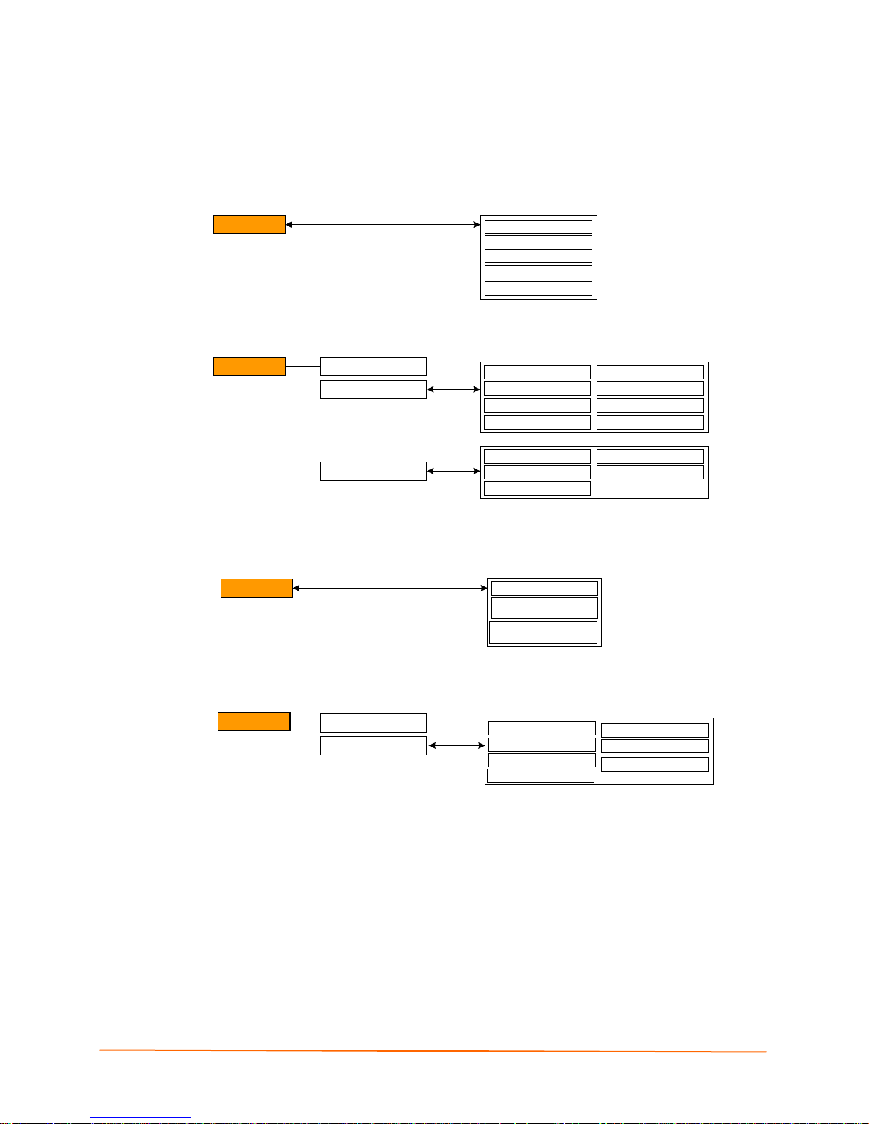
6: Configuration Using the Web Manager
Syslog
Syslog
Host
Local Port
Remote Port
Severity to Log
Statistics
Configuration
Authentication
HTTP Server
HTTP Port
HTTPS Port
Max Timeout
Max Bytes
Logging
Max Log Entries
Log Format
URI
Realm
Auth Type
Username
Password
HTTP
Statistics
Configuration
Telnet Access
Telnet Port
SSH Access
SSH Port
Password
Enable Password
CLI
Quick Connect Line
RSS Feed On/Off
Persistent
RSS
Max Entries
Figure 6-5 Web Manager Menu Structure (3 of 5)
(continued on next page)
IntelliBox-I/O 2100 User Guide 46
Page 47

6: Configuration Using the Web Manager
Figure 6-6 Web Manager Menu Structure (4 of 5))
IntelliBox-I/O 2100 User Guide 47
(continued on next page)
Page 48

6: Configuration Using the Web Manager
Figure 6-7 Web Manager Menu Structure (5 of 5)
IntelliBox-I/O 2100 User Guide 48
Page 49

6: Configuration Using the Web Manager
Understanding the Web Manager Pages
Figure 6-8 shows the areas of the Web Manager page.
Figure 6-8 Components of the Web Manager Page
The header always displays at the top of the page. The header information remains the
same regardless of the page displayed.
The menu bar always displays at the left side of the page, regardless of the page
displayed. The menu bar lists the names of the pages available in the Web Manager. To
display a page, click it in the menu bar.
When you click the name of a page in the menu bar, the page displays in the main area.
The main area of most pages contains two sections:
IntelliBox-I/O 2100 User Guide 49
Page 50

The top section lets you select or enter new configuration settings. After you change
settings, click the Submit button to apply the change. Some settings require you to
reboot the IntelliBox before the settings take effect. Those settings are identified in
the appropriate sections in this chapter.
The bottom section shows the current configuration.
The information area shows information or instructions associated with the page.
The footer displays at the bottom of the page. It contains copyright information and a link
to the Lantronix home page.
Device Status Page
The Device Status page is the first page that displays when you log into the Web
Manager. It also displays when you click the Status link in the menu bar. This read-only
page shows the IntelliBox product information, network settings, line settings, and
tunneling settings.
Figure 6-9 Device Status Page (IntelliBox-I/O 2100)
6: Configuration Using the Web Manager
IntelliBox-I/O 2100 User Guide 50
Page 51

7: Network, Serial Line, Tunnel, and Modbus
Settings
Network Configur ation Page
Clicking the Network link in the menu bar displays the Network Configuration page. Here
you can change the following IntelliBox network configuration settings:
BOOTP and DHCP client
IP address, network mask, and gateway
Hostname and domain
DHCP client ID
Ethernet transmission speed
Figure 7-1 Network Configuration
IntelliBox-I/O 2100 User Guide 51
Page 52

7: Network, Serial Line, Tunnel, and Modbus Settings
The After Reboot column in the Current Configuration section of this page shows the
settings that will take effect the next time the IntelliBox reboots.
Changes to the following settings require you to reboot the IntelliBox before the new
settings take effect:
BOOTP Client
DHCP Client
IP Address
Network Mask
DHCP Client ID
Note: Some settings in the Current Configuration section, such as IP Address
and Network Mask have a Delete link you can click to delete the setting. If you
click this link, a warning message asks whether you are sure you want to delete
the setting. Click OK to delete the setting or Cancel to keep it.
Table 7-1 Network Configuration Page Settings
Network
Description
Configuration
Page Settings
BOOTP Client Select whether the IntelliBox should send BOOTP requests. Changing
this value requires the IntelliBox to be rebooted. Choices are:
On = IntelliBox sends BOOTP requests on a DHCP-managed network.
This setting overrides the configured IP address, network mask,
gateway, host name, and domain settings. If DHCP is set to On, the
IntelliBox automatically uses DHCP, regardless of whether BOOTP
Client is set to On.
Off = IntelliBox does not se nd BO OT P requests.
DHCP Client Select whether the IntelliBox IP address is automatically assigned by a
DHCP server. Changing this value requires you to reboot the IntelliBox.
Choices are:
On = IntelliBox receives its IP address automatically from a DHCP
server, regardless of the BOOTP Client setting. This setting overrides the
configured IP address, network mask, gateway, host name, and domain
settings.
Off = IntelliBox does not receive its IP address automatically.
IP Address Enter the IntelliBox static IP address. The IP address consists of four
octets separated by a period and is used if BOOTP and DHCP are both
set to Off. Changing this value requires you to reboot the IntelliBox.
Note: When DHCP is enabled, the IntelliBox tries to obtain an IP address
from DHCP. If it cannot, the IntelliBox uses an Auto IP address in the
range of 169.254.xxx.xxx.
Network Mask Enter the IntelliBox subnet mask. The subnet mask consists of four
octets separated by a period. Changing this value requires you to reboot
the IntelliBox.
Note: When DHCP is enabled, the IntelliBox tries to obtain a network
mask from DHCP. If it cannot, the IntelliBox uses a network mask of
255.255.0.0.
IntelliBox-I/O 2100 User Guide 52
Page 53

7: Network, Serial Line, Tunnel, and Modbus Settings
Network
Description
Configuration
Page Settings
Gateway Enter the router IP address from the local LAN the IntelliBox is on. The
address consists of four octets separated by a period.
Hostname Enter the IntelliBox host name. The host name can be up to 31
characters with no spaces.
Domain Enter the IntelliBox domain name.
DHCP Client ID Enter a DHCP ID if used by the DHCP server. Changing this value
requires the IntelliBox to be rebooted.
Primary DNS IP address of the primary name server. This entry is required if you
choose to configure the DNS (Domain Name Server) servers.
Secondary DNS IP address of the secondary name server.
IntelliBox-I/O 2100 User Guide 53
Page 54

Line Settings Pages
The Line Settings page displays the status and statistics for each of the serial lines
(ports). This page also lets you change the character format and command mode settings
for the serial lines.
To select a line, click Line 1 or Line 2 at the top of the page.
After you select a serial line, you can click Statistics, Configuration, or Command
Mode to view and change the settings of the selected s er ial line. Because all serial lines
operate independently, you can specify different configuration settings for each line.Line
– Statistics Page
The Line – Statistics page displays when you click Line in the menu bar. It also displays
when you click Statistics at the top of one of the other Line Settings pages. This readonly page shows the status and statistics for the serial line selected at the top of this
page.
7: Network, Serial Line, Tunnel, and Modbus Settings
Figure 7-2 Line – Statistics Page
IntelliBox-I/O 2100 User Guide 54
Page 55

7: Network, Serial Line, Tunnel, and Modbus Settings
Line - Configuration Page
If you click Configuration at the top of one of the Line Settings pages, the Line –
Configuration page displays. This page shows the configuration settings for the serial line
selected at the top of the page and lets you change the settings for that serial line.
Figure 7-3 Line – Configuration Page
IntelliBox-I/O 2100 User Guide 55
Page 56

7: Network, Serial Line, Tunnel, and Modbus Settings
below.
Table 7-2 Configuration Page
Line –
Description
Configuration
Page Settings
Name (optional) Enter a name for the serial port. The name may have up to 25
characters.
Interface Line 1 is always RS232.
For Line 2, select the RS485 duplex mode. Choices are:
RS485 Half Duplex (default)
RS485 Full-Duplex
Termination
(line 2 only)
State Select to enable or disable the current line.
Protocol Select the protocol used on the current serial line. Choices are:
Select to enable or disable RS-485 termination.
None
Tunnel (default)
Modbus RTU
Modbus ASCII
LPD
LPD or Tunnel
Note: Modbus protocols change the display in sev eral fie lds
Baud Rate Select the baud rate for the currently selected serial port.
Choices are:
300 baud to 230,400 baud. (Default is 9600 baud.)
Custom = lets you enter in the Custom text box a speed other
than those shown.
Note: Any baud rate over 19200, Lantronix requests flow control
usage.
Parity Select the parity used by the currently selected serial line.
Choices are:
None (default)
Even (default for Modbus RTU and Modbus ASCII)
Odd
Data Bits Select the number of data bits used by the currently selected
serial line. Choices are:
7
8 (default)
For the Modbus protocols, this setting cannot be changed.
For Modbus RTU, the setting is 8. For Modbus ASCII, the setting
is 7.
IntelliBox-I/O 2100 User Guide 56
Page 57

7: Network, Serial Line, Tunnel, and Modbus Settings
Line –
Description
Configuration
Page Settings
Stop Bits Select the number of stop bits used by the currently selected
serial line. Choices are:
1 (default)
2
For the Modbus protocols, the default is 1; this setting
automatically changes to 2 if parity is None.
Flow Control Select the flow control method used by the currently selected
serial line. Choices are:
None (default for Tunnel protocol)
Hardware (commonly called CTS/RTS)
Software (commonly called Xon/Xoff)
On Line 1, for the Modbus protocols, Flow Control defaults to
None; this setting cannot be changed.
On Line 2, Flow Control is unavailable for all protocols.
Xon char Character to use to initiate a flow of data.
When Flow Control is set to Software, specif y Xon char. Prefix
a decimal character with \ or a hexadecimal character with 0x, or
provide a single printable character. The default Xon char is
0x11.
Xoff char
When Flow Control is set to Software, specif y Xo ff char. Prefix
a decimal character with \ or a hexadecimal character with 0x, or
provide a single printable character. The default Xoff char is
0x13.
IntelliBox-I/O 2100 User Guide 57
Page 58

7: Network, Serial Line, Tunnel, and Modbus Settings
Line – Command Mode Page
If you click Command Mode at the top of one of the Line Settings pages, the Line –
Command Mode page displays. This page shows the command mode settings for the
serial line selected at the top of the page and lets you change the settings for that serial
line.
Figure 7-4 Line – Command Mode Page
IntelliBox-I/O 2100 User Guide 58
Page 59

7: Network, Serial Line, Tunnel, and Modbus Settings
Table 7-3 Line – Command Mode Page
Line –
Description
Command
Mode Page
Settings
Mode Select the method of enabling command mode or choose to disable
command mode. Choices are:
Always = immediately enables command mode for the serial line.
Use Serial String = enables command mode when the serial string is
read on the serial line during boot time.
Disabled = Disables command mode.
Wait Time Enter the maximum number of milliseconds the selected serial line waits
to receive the specific serial string at boot time to enter command mode.
Default is 5000 milliseconds.
Serial String Enter the serial string that places the serial line into command mode.
After entering a string, use the buttons to indicate whether the string is a
text or binary value.
Echo Serial
String
Signon
Message
Select whether the serial line echoes the specified serial string at boot
time. Choices are:
Yes = echoes the characters specified in the Serial String text box.
No = does not echo the characters specifie d in the Serial String text
box.
Enter a message to send on the serial line at bootup. Select Text or
Binary to indicate the form of the entry.
IntelliBox-I/O 2100 User Guide 59
Page 60

Tunnel Pages
The Tunnel pages let you view and configure settings for tunnels. (For more information,
see Tunneling.)
To select a tunnel, click Tunnel 1 or Tunnel 2 at the top of the page.
After you select a tunnel, you can click Statistics, Serial Settings, Start/Stop Chars,
Accept Mode, Connect Mode, Disconnect Mode, Packing Mode, or Modem
Emulation to view and change the settings of the selected tunnel. Because all tunnels
operate independently, you can specify different configuration settings for each tunnel.
Tunnel – Statistics Page
The Tunnel – Statistics page displays when you click Tunnel in the menu bar. It also
displays when you click Statistics at the top of one of the other Tunnel pages. This readonly page shows the status and statistics for the tunnel currently selected at the top of
this page.
7: Network, Serial Line, Tunnel, and Modbus Settings
Figure 7-5 Tunnel - Statistics Page
IntelliBox-I/O 2100 User Guide 60
Page 61

7: Network, Serial Line, Tunnel, and Modbus Settings
Tunnel – Serial Settings Page
If you click Serial Settings at the top of one of the Tunnel pages, the Tunnel – Serial
Settings page displays. This page shows the settings for the tunnel selected at the top of
the page and lets you change the settings. If you change the Buffer Size value, you must
reboot the IntelliBox for the change to take effect. Changing the other values does not
require a reboot.
Under Current Configuration, Buffer Size has a Reset link that lets you reset the buffer
size to its default value. If you click this link, a message tells you that you will have to
reboot the IntelliBox. Click OK to proceed or Cancel to cancel the operation.
Note: The default protocol is Tunnel. The protocol on the line 1 page must be
Tunnel for tunneling to operate.
Figure 7-6 Tunnel – Serial Settings Page
Table 7-4 Tunnel – Serial Settings Page
Tunnel –
Description
Serial
Settings Page
Line Settings Lists current serial settings for the line.
Protocol Lists the protocol being used on the line.
Buffer Size Enter the size of the buffer used to receive data on the serial line.
Range = 1 to 4096 bytes. Default is 2048 bytes. Changing this value
requires you to reboot the IntelliBox.
DTR
Select Asserted while conne cted to assert DTR whenever a connect or
an accept mode tunnel connection is active. Select Continuously
Asserted (default) to assert DTR regardless of the status of a tunnel
connection.
Unasserted sets DTR off always.
IntelliBox-I/O 2100 User Guide 61
Page 62

7: Network, Serial Line, Tunnel, and Modbus Settings
Tunnel – Start/Stop Characters Page
If you click Start/Stop Chars at the top of one of the Tunnel pages, the Tunnel –
Start/Stop Chars page displays. This page shows the start and stop characters used for
the tunnel selected at the top of the page and lets you change the settings for that tunnel.
Figure 7-7 Tunnel – Start/Stop Chars Page
IntelliBox-I/O 2100 User Guide 62
Page 63

7: Network, Serial Line, Tunnel, and Modbus Settings
Table 7-5 Tunnel – Start/Stop Chars Page
Tunnel –
Description
Start/Stop Chars
Page Settings
Start Character Enter the start character. When this character is read on the
serial line, it either initiates a new connection (for a tunnel in
Connect Mode) or enables a tunnel in Accept Mode to start
listening for connections. Default is <none>.
Stop Character Enter the stop character. When this character is read on the
serial line, it disconnec ts an ac tiv e tunnel con nec tion . Default is
<none>.
Echo Start
Character
Echo Stop
Character
Select whether the start character is forwarded (or “echoed’)
through the selected tunnel when the serial line is read. Choices
are:
On = echo the start character on the selected tunnel when the
serial line is read.
Off = do not echo the start character. (default)
Select whether the stop character is echoed through the
selected tunnel when the serial line is read. Choices are:
On = echo the stop character on the selected tunnel when the
serial line is read.
Off = do not echo the stop character. (default)
IntelliBox-I/O 2100 User Guide 63
Page 64

7: Network, Serial Line, Tunnel, and Modbus Settings
Tunnel – Accept Mode Page
Accept Mode determines how the IntelliBox “listens” for an incoming connection. If yo u
click Accept Mode at the top of one of the Tunnel pages , the Tunnel – Accept Mode
page displays. Here you can select the method for starting a tunnel in Acc ept Mode and
select other settings for the tunnel selected at the top of the page.
For more information about Accept Mode, see Accept Mode.
Figure 7-8 Tunnel – Accept Mode Page
IntelliBox-I/O 2100 User Guide 64
Page 65

7: Network, Serial Line, Tunnel, and Modbus Settings
Table 7-6 Tunnel – Accept Mode Page
Tunnel –
Description
Accept Mode
Page Settings
Mode Select the method used to start a tunnel in Accept Mode. Choices are:
Disable = do not accept an incoming connection.
Always = accept an incoming connection. (default)
Any Character = start waiting for an incoming connection when any
character is read on the serial line.
Start Character = start waiting for an incoming connection when the
start character for the selected tunnel is read on the serial line.
Modem Control Asserted = start waiting for an incoming connection as
long as the Modem Control pin (DSR) is asserted on the serial line until
a connection is made.
Modem Emulation = start waiting for an incoming connection when
triggered by modem emulation AT commands. Connect Mode must also
be set to Modem Emulation.
Local Port Enter the number of the local port used to receive (or listen for) packets.
Default is 10001 for Tunnel 1, 10002 for Tunnel 2, and so forth.
Protocol Select the protocol to be used on the connection. Choices are:
TCP (default)
SSH
SSL
TCP
TCP/AES
Telnet
TCP Keep Alive Specify the number of milliseconds the IntelliBox waits during an
inactive connection before checking the status of the connection. If the
IntelliBox does not receive a response from the remote host, it drops
that connection.
AES Encrypt Key Specify the Advanced Encryption Standard (AES) key string to be used
for encrypting outgoing data in Accept Mode tunneling. Then, select the
key form:
Text
Hexadecimal
AES Decrypt Key Specify the Advanced Encryption Standard (AES) key string to be used
for decrypting incoming data in Accept Mode tunneling. Then, select the
key form:
Text Hexadecimal
Flush Serial Select whether the serial line is flushed when a connection is made.
Choices are:
Enabled = flush the serial line when a connection is made.
Disabled = do not flush the serial line. (default)
IntelliBox-I/O 2100 User Guide 65
Page 66

7: Network, Serial Line, Tunnel, and Modbus Settings
Tunnel –
Description
Accept Mode
Page Settings
Block Serial
Block Network
Password Enter a password that clients must send to the IntelliBox within 30
Prompt for
Password
Select whether incoming serial data should be discarded. This setting is
used for debugging purposes. Choices are:
On = discard all incoming serial data on the respective interface.
Off = do not discard all incoming serial data. (default)
Select whether incoming network data should be discarded. This setting
is used for debugging purposes. Choices are:
On = discard all incoming network data on the respective interface.
Off = do not discard all incoming network data. (default)
seconds from opening a network connection to enable data
transmission.
The password can have up to 31 characters and must contain only
alphanumeric characters and punctuation. When set, the password sent
to the IntelliBox must be terminated with one of the following: (a) 0x10
(LF), (b) 0x00, (c) 0x13 0x10 (CR LF), or (d) 0x13 0x00.
Indicate whether the user should be prompted for the password upon
connection.
Enabled = prompt for a password upon connection.
Disabled = do not prompt for a password upon connection.
Email on Connect Select whether an email is sent when a connection is made.
None = do not send an email.
Email # = send an email corresponding to the tunnel number.
Email on
Disconnect
Output Selection Select the output to be closed while a connection is active.
Mode Select whether the same output may also be closed by another
RSS Trace
Connections
Select whether an email corresponding to the tunnel number is sent
when a connection is closed.
None = do not send an email.
Email # = send an email corresponding to the tunnel number.
None
XI01 = output from digital port 1
XI02 = output from digital port 2
Relay = output from the relay
condition (e.g. Connect Mode settings from Tunnel 1 and Tunnel 2 for
the same digital port.)
Exclusive Control = same output may not be closed by another
condition.
Logical-Or = same output may be closed by another condition.
Select to enable or disable RSS Trace Connections.
IntelliBox-I/O 2100 User Guide 66
Page 67

7: Network, Serial Line, Tunnel, and Modbus Settings
Tunnel – Connect Mode Page
Connect Mode determines how the IntelliBox initiates a connection to a remote host or
device. If you click Connect Mode at the top of one of the Tunnel pages, the Tunnel –
Connect Mode page displays. Here you can select the method for starting a tunnel in
Connect Mode and select other settings for the tunnel selected at the top of the page. A
tunnel, like an LPD is directed to a single serial port.
Any configuration changes you make on the displayed page apply to the tunnel y ou
selected at the top of this page. For example, if Tunnel 1 is selected, any configuration
changes you make apply to tunnel 1.
Under Current Configuration, Remote Address has a Delete link that lets you delete
the remote address shown. If you click this link, a message tells you that your action may
stop an active connection. Click OK to proceed or Cancel to cancel the operation.
Remote Port defaults to Random. If you have configured a specific port number, a
Random link displays that enables you to restore the default. For more information about
Connect Mode, see Connect Mode.
Figure 7-9 Tunnel -- Connect Mode Page
IntelliBox-I/O 2100 User Guide 67
Page 68

7: Network, Serial Line, Tunnel, and Modbus Settings
Table 7-7 Tunnel -- Connect Mode Settings
Tunnel – Connect
Description
Mode Page
Settings
Mode Select the method used to start a tunnel in Accept Mode. Choices
are:
Disable = do not accept an incoming connection.
Always = accept an incoming connection. (default)
Any Character = start waiting for an incoming connection when any
character is read on the serial line.
Start Character = start waiting for an incoming connection when the
start character for the selected tunnel is read on the serial line.
Modem Control Asserted = start waiting for an incoming connection
as long as the Modem Control pin (DSR) is asserted on the serial line
until a connection is made.
Modem Emulation = start waiting for an incoming connection when
triggered by modem emulation AT commands. Connect Mode must
also be set to Modem Emulation.
Remote Address Enter the address of the remote host to which the selected tunnel will
connect. Default is <none>.
Remote Port Enter the number of the remote port to which the selected tunnel will
connect. Default is <none>.
Local Port Enter the number of the local port used to receive (or listen for)
packets. Random by default, but can be overridden.
Protocol Select the protocol to be used on the connection. Choices are:
TCP (default)
SSH SSL
TCP
TCP/AES
Telnet
UDP
UDP/AES
TCP Keep Alive Specifies the number of milliseconds the IntelliBox waits during an
AES Encrypt Key Specify the Advanced Encryption Standard (AES) key string to be used
AES Decrypt Key Specify the Advanced Encryption Standard (AES) key string to be used
IntelliBox-I/O 2100 User Guide 68
inactive connection before checking the status of the connection. If
the IntelliBox does not receive a response from the remote host, it
drops that connection.
for encrypting outgoing data in Connect Mode tunneling. Then, select the
key form:
Text
Hexadecimal
for decrypting incoming data in Connect Mode tunneling. Then, select the
key form:
Text
Hexadecimal
Page 69

7: Network, Serial Line, Tunnel, and Modbus Settings
Tunnel – Connect
Description
Mode Page
Settings
Reconnect Timer Enter the maximum number of milliseconds to wait before trying to
reconnect to the remote host after a previous attempt failed or the
connection was closed. Default is 15000 milliseconds.
Flush Serial Data Select whether to flush the serial line when a connection is made.
Choices are:
Enabled = flush the serial line when a connection is made.
Disabled = do not flush the serial line. (default)
SSH Username If you selected SSH as the protocol for this tunnel, enter the SSH
client user that is to be used for the SSH connection. Default is
<none>.
Block Serial Select whether incoming block serial data should be discarded. This
setting is used for debugging purposes. Choices are:
On = discard all incoming serial data on the respective interface.
Off = do not discard all incoming serial data. (default)
Block Network Select whether incoming block network data should be discarded.
This setting is used for debugging purposes. Choices are:
On = discard all incoming network data on the respective interface.
Off = do not discard all incoming network data. (default)
Email on Connect Select whether email should be sent when a connection is made.
None = do not send an email.
Email # = send an email corresponding to the tunnel number.
Email on Disconnect Select whether email should be sent when a connection is closed.
None = do not send an email.
Email # = send an email corresponding to the tunnel number.
Output Select Select the output to be closed while a connection is active.
XI01 = Output from digital port 1
XI02 = Output from digital port 2
Relay = Output from the relay
Mode Select whether the same output may also be closed by another
condition, (e.g. Connect Mode settings from Tunnel 1 and Tunnel 2
for the same digital port.)
Exclusive Control = The same output may not be closed by another
condition.
Logical-Or = The same output may be closed by another condition.
IntelliBox-I/O 2100 User Guide 69
Page 70

7: Network, Serial Line, Tunnel, and Modbus Settings
Tunnel – Disconnect Mode Page
If you click Disconnect Mode at the top of one of the Tunnel pages, the Tunnel –
Disconnect Mode page displays. Here you can select the disconnect method for the
tunnel selected at the top of the page. For more information about Disconnect Mode, see
Disconnect Mode.
Figure 7-10 Tunnel – Disconnect Mode Page
Table 7-8 Tunnel – Disconnect Mode Page
Tunnel –
Description
Disconnect Mode
Page Settings
Character Stop Select whether to enable disconnect when the “Stop Character”
(configured on the “Start/Stop Chars” page) is read on the serial line.
Choices are:
Enabled
Disabled
Modem Control Select whether to enable disconnect when the modem control pin is not
asserted on the serial line. Choices are:
Enabled
Disabled
Timeout Enter the idle time, in milliseconds, that must elapse for a connection
before it is disconnected. Default is 60000 milliseconds. The value 0
(zero) disables the idle timeout.
Flush Serial Data Select whether the serial line should be flushed when a connection is
disconnected. Choices are:
Enabled = flush the serial line when a connection is disconnected.
Disabled = do not flush the serial line. (default)
IntelliBox-I/O 2100 User Guide 70
Page 71

7: Network, Serial Line, Tunnel, and Modbus Settings
Tunnel – Packing Mode Page
When tunneling, data can be packed (queued) and sent in large chunks on the network
instead of being sent immediately after being read on the serial line. If you click Packing
Mode at the top of one of the Tunnel pages, the Tunnel – Packing Mode page displays.
Here you can select packing settings for the tunnel selected at the top of the page. For
more information about Packing Mode, see Packing Mode.
Figure 7-11 Tunnel – Packing Mode Page
Table 7-9 Tunnel – Packing Mode Page
Tunnel – Packing
Description
Mode Page
Settings
Mode Select the method used to pack data. Choices are:
Disabled = data is never packed. (default)
Timeout = data is sent after the timeout elapses.
Send Character = data is sent when the send character is read on
the serial line.
Timeout Enter the maximum number of milliseconds to wait before sending
queued data across the network. Default is 1000 milliseconds.
Threshold Enter the queued data limit that, when reached, immediately sends
queued data to the network. Default is 512 bytes.
Send Character Enter the send character. When this character is read on the serial
line, it forces the queued data to be sent immediately. Default is
<none>.
Trailing Character Enter the trailing character. This character is inserted into the
outgoing data stream immediately after the send character. Default is
<none>.
IntelliBox-I/O 2100 User Guide 71
Page 72

7: Network, Serial Line, Tunnel, and Modbus Settings
Tunnel – Modem Emulation Page
A tunnel in Connect Mode can be initiated using modem commands incoming from the
serial line. If you click Modem Emulation at the top of one of the Tunnel pages, the
Tunnel – Modem Emulation page displays. Here you can select modem emulation
settings for the tunnel selected at the top of the page. For more information about modem
emulation, see Modem Em ulat io n.
Tunnel – Modem Emulation Page
IntelliBox-I/O 2100 User Guide 72
Page 73

7: Network, Serial Line, Tunnel, and Modbus Settings
Table 7-10 Tunnel – Modem Emulation Page
Tunnel – Modem
Description
Emulation Page
Settings
Echo Pluses Select whether the modem +++ escape sequence is echoed
(sent). Choices a re:
On = modem pluses are sent into the network.
Off = modem pluses are suppressed. (default).
Echo Commands Select whether modem commands are echoed on the serial line.
Choices are:
On = modem commands are echoed. (default)
Off = modem commands are not echoed.
Verbose Response
Codes
Response Codes Select whether modem response (result) codes sent on the serial
Error Unknown
Commands
Select whether modem response (result) codes are sent on the
serial line. Choices are:
Text = modem responses are sent on the serial line. (default)
Numeric = modem responses are not sent.
line take the form of words or numbers. Choices are:
Text = modem responses are sent as words. (default)
Numeric = modem responses are sent as numbers.
Select whether an ERROR or OK response is sent in reply to
unrecognized AT commands. Choices are:
On = ERROR is returned for unrecognized AT commands.
Off = OK is returned for unrecognized AT commands. (default)
Incoming Connection Select how to manage incoming requests. Choices are:
Disabled = disable requests (ATS0=0)
Automatic = automatically answer requests (ATS0=1)
Manual = manually answer requests via the ATA command after
an incoming RING (ATS0=2)
Connect String If required, enter a customized string that is sent along with the
CONNECT response code. Default is <none>.
Display Remote IP Select whether to enable an incoming RING followed by the IP
address of the caller. Choices are:
Enabled
Disabled
IntelliBox-I/O 2100 User Guide 73
Page 74

Modbus Pages
The Modbus pages let you view and configure settings for Modbus servers listening on
the TCP ports. (For more information, see the appendix, C: Modbus.)
Modbus – Statistics Page
The Modbus – Statistics page displays when you click Modbus in the menu bar. It also
displays when you click Statistics at the top of the Modbus - Configuration page. This
page shows the status and statistics for up to two Modbus servers. The standard TCP
server port number is 502.
When a connection is active, the remote client information displays as well as the number
of Protocol Data Units (PDUs) that have been sent and received. This is a count of
messages, not bytes. If a connection is active, a Kill link (at its right)) enables you to
close the connection.
7: Network, Serial Line, Tunnel, and Modbus Settings
Figure 7-12 Modbus – Statistics Page
IntelliBox-I/O 2100 User Guide 74
Page 75

7: Network, Serial Line, Tunnel, and Modbus Settings
Modbus – Configuration Page
If you click Configuration at the top of one of the Modbus – Statistics page, the Modbus
Configuration page disp lays. Modbus Configuration enables you to add a Modbus
server.
The Modbus server, if enabled, is active on TCP port 502. You have the option of using
an additional port.
Figure 7-13 Modbus – Configuration Page
Table 7-11 Modbus – Configuration Page
Modbus –
Description
Configuration
Page Settings
TCP Server State Select whether to enable a second Modbus server to have access.
Choices are:
On = Modbus server is enabled. (default)
Off = Modbus server is disabled.
Additional TCP
Server Port
Response
Timeout
Enter the number of the TCP port on which the IntelliBox additional server
listens for connections.
Indicate the response timeout in milliseconds. Mus t be a minimum of 10
msec.
IntelliBox-I/O 2100 User Guide 75
Page 76

8: Terminal and Host Settings
This chapter describes how to view and configure the Terminal Login Connect Menu and
associated Host configuration. The Terminal Login Connect Menu feature allows the
IntelliBox device to present a menu of predefined connections when the device is
accessed via telnet, ssh, or a serial port. From the menu, a user can choose one of the
presented options and the device automatically makes the predefined connection.
The Terminal page controls whether a Telnet, SSH, or serial port connection presents the
CLI or the Login Connect Menu. By default, the CLI is presented when the device is
accessed. When configured to present the Login Connec t Menu, the hos ts conf igur ed via
the Hosts page, and named serial lines are presented.
Terminal Settings
This page shows configuration settings for each terminal connection method. You can
configure whether each serial line or the telnet/SSH server presents a CLI or a Login
Connect manu when a connection is made.
Figure 8-1 Terminal on Network and Line
IntelliBox-I/O 2100 User Guide 76
Page 77

8: Terminal and Host Settings
enabled.
Table 8-1 Terminal on Network and Line Settings
Terminal on
Description
Network and Line
Settings
Terminal Type Enter the Terminal Type to be sent from the host via IAC.
Note: IAC means “interpret as command”. It is a way to send
commands over the networks such as send break or start
echoing.
Login Connect Menu Select the interface to display when the user logs in. Choices are:
Enabled = shows the Login Connect menu
Disabled = shows the CLI (default)
Exit Connect Menu Select whether to display a choice for the user to exit the Login
Connect menu and reach the CLI. Choices are:
Enabled = a choice allows the user to exit to the CLI
Disabled = there is no exit to the CLI (default)
Send Break Enter a Send Break control character, e.g., <control> Y, or keep
blank to disable. When the Send Break control character is
received from the network on its way to a Serial Line, it will not be
sent to the Line; instead, the line output will be forced inactive.
Note: This configuration option is only available for Line
Terminals.
Break Duration Specify, in milliseconds, how long the “spacing”condition will be
placed on the line when a break is sent. May enter a value up to
10000. Default is 500.
Note: This configuration option is only available for Line
Terminals.
Echo Select whether to enable echo. Choices are:
Enabled
Disabled
Note: Applies only to Connect Mode Telnet connections, not to
Accept Mode. Only disable Echo if your terminal echoes, in which
case you will see double of each character typed. Default is
IntelliBox-I/O 2100 User Guide 77
Page 78

Host Configuration
characters. To leave a host out of the menu, leave this field blank.
Select the protocol to use to connect to the host. Choices are:
The Host page is where you view and configure settings for a remote host.
8: Terminal and Host Settings
Figure 8-3 Host Configuration
Table 8-2 Host Configuration
Host Settings Description
Name
Protocol
SSH Username
Remote Address Enter an IP address for the host to which the device will connect.
Remote Port Enter the port on the host to which the device will connect.
Enter a name for the host. This name appears on the Login
Connect Menu. The maximum length of the host name is 63
Telnet
SSH
Note: SSH Keys must be loaded or created in SSH for the SSH
protocol to work.
Enter a username to select a pre-configured Username/Password/
Key (configured on the SSH: Client Users), or leave it blank to be
prompted for a username and password at connect time.
Note: This field appears if you selected SSH as the protocol.
IntelliBox-I/O 2100 User Guide 78
Page 79

9: Services Settings
DNS Page
Clicking the DNS link in the menu bar displays the DNS page. This page displays and
allows changes to configuration settings for the domain name system (DNS).
The DNS page also shows any contents in the DNS cache. When a DNS name is
resolved using a forward lookup, the results are stored in the DNS cache temporarily.
The IntelliBox consults this cache when performing forward lookups. Each item in the
cache eventually times out and is removed automatically after a certain period, or you
can delete it manually.
Figure 9-1 DNS Page
Note: If the current configuration shows an address comes from DHCP or
BOOTP, the new static address overrides it until you reboot the device.
Table 9-1 DNS Page
DNS Page
Settings
Primary DNS Enter the DNS primary server that maintains the master zone information/file
Secondary DNS Enter the DNS secondary server that backs up the primary DNS server for a
DNS Cache Lists the e ntries in the cache.
Description
for a domain. Default is <none>.
zone. Default is <none>.
IntelliBox-I/O 2100 User Guide 79
Page 80

SNMP Page
Clicking the SNMP link in the menu bar displays the SNMP page. This page is used to
configure the Simple Network Management Protocol (SNMP) agent. Using this page, you
can configure the SNMP service to send a trap when it receives a request for information
that contains an incorrect community name and does not match an accepted system
name for the service.
Under Current Configuration, several settings have a Delete link that lets you delete
these settings. If you click these links, a message asks whether you are sure you want to
delete this information. Click OK to proceed or Cancel to cancel the operation.
9: Services Settings
Figure 9-2 SNMP Page
IntelliBox-I/O 2100 User Guide 80
Page 81

9: Services Settings
Table 9-2 SNMP Page
SNMP Page Settings Description
SNMP Agent Select whether SNMP is enabled. Choices are:
On = SNMP is enabled. (default)
Off = SNMP is disabled.
Read Community Enter the case-sensitive community name from which the
IntelliBox will receive trap messages. Default is public. For
security, the read community name displays as <Configured>
to show that one is enabled.
Write Community Enter the case-sensitive community name to which the
IntelliBox will send trap messages. Default is private. For
security, the write community name displays as <Configured>
to show that one is enabled.
System Contact Enter the name of the system contact. Default is <None>.
System Name Enter the IntelliBox’s name.
System Description Enter a system description for the IntelliBox.
System Location Enter the geographic location of the IntelliBox. Default is
<None>.
Enable Traps Select whether SNMP cold start trap messa ges are enab led
at boot. Choices are:
On = SNMP cold start trap messages are enabled at boot
time. (default)
Off = SNMP traps are disabled.
Primary Trap Dest IP Enter the primary SNMP trap host. Default is <None>.
Secondary Trap Dest IP Enter the secondary SNMP trap host. Default is <None>.
IntelliBox-I/O 2100 User Guide 81
Page 82

FTP Page
Clicking the FTP link in the menu bar displays the FTP page. This page displays the
current File Transfer Protocol (FTP) connection status and various statistics about the
FTP server.
Under Current FTP Configuration and Statistics, FTP Password has a Reset link that
lets you reset the FTP password. If you click this link, a message asks whether you are
sure you want to reset this information. Click OK to proceed or Cancel to cancel the
operation.
9: Services Settings
Figure 9-3 FTP Page
Table 9-3 FTP Page
FTP Page
Description
Settings
FTP Server Select whether the FTP server is enabled. Choices are:
On = FTP server is enabled. (default)
Off = FTP server is disabled.
FTP Username Enter the username required to gain FTP access. Default is admin.
FTP Password Enter the password associated with the username. Default is PASS.
IntelliBox-I/O 2100 User Guide 82
Page 83

TFTP Page
Clicking the TFTP link in the menu bar displays the TFTP page. This page displays the
status and various statistics about the Trivial File Transfer Protocol (TFTP) server.
9: Services Settings
Figure 9-4 TFTP Page
Table 9-4 TFTP Page
TFTP Page Settings Description
TFTP Server Select whether the TFTP server is enabled. Choices are:
On = TFTP server is enabled. (default)
Off = TFTP server is disabled.
Allow TFTP File
Creation
Select whether the TFTP server can create a file if it does not
already exist. If you enable this feature, it exposes the IntelliBox
to possible Denial-of-Service (DoS) attacks against the
filesystem. Choices are:
On = files can be created by the TFTP server.
Off = files cannot be created by the TFTP server. (default)
IntelliBox-I/O 2100 User Guide 83
Page 84

Syslog Page
Enter the number for the port on the remote serv er that sup p or ts
Clicking the Syslog link in the menu bar displays the Syslog page. This page shows the
current configuration, status, and statistics for the syslog. Here you can configure the
syslog destination and the severity of the events to log.
9: Services Settings
Figure 9-5 Syslog Page
Table 9-5 Syslog Page
Syslog Page
Description
Settings
Host Enter the IP address of the remote server from which system
logs are sent for storage.
Local Port Enter the number for the loc al port on the IntelliBox from which
system logs are sent. The default is 514.
The system log is always saved to local storage, but it is not
retained through reboots. Saving the system log to a server that
supports remote logging servic es (see RFC 3164) enables the
administrator to save the complete system log history.
Remote Port
Severity to Log From the drop-down box, select the minimum level of system
logging services. The default is 514.
message the IntelliBox should log. This setting applies to all
syslog facilities. The drop-down list is in descending order of
severity, e.g., Emergency is more severe than Alert.
IntelliBox-I/O 2100 User Guide 84
Page 85

HTTP Pages
Clicking the HTTP link in the menu bar displays the HTTP Statistics page. This page has
three links at the top for viewing statistics and for viewing and changing configuration and
authentication settings.
HTTP Statistics Page
The HTTP Statistics page displays when you click HTTP in the menu bar. It also displays
when you click Statistics at the top of one of the other HTTP pages. This read-only page
shows various statistics about the Hyper Text Transfer Protocol (HTTP) server.
Note: The HTTP log is a scrolling log, with the last Max Log Entries cached and
viewable. To change the maximum number of entries that can be viewed, go to
the HTTP Configuration Page.
9: Services Settings
Figure 9-6 HTTP Statistics Page
HTTP Configurati on Page
If you click Configuration at the top of one of the HTTP pages, the HTTP Configuration
page displays. Here you can change HTTP configuration settings.
Under Current Configuration, Logs has View and Clear links that let you view or clear
the log. If you click View, the log displays. If you click Clear, a message asks whether
you are sure you want to delete this information. Click OK to proceed or Cancel to cancel
the operation.
Note: For help changing the format of the log, see Log Format Directives.
IntelliBox-I/O 2100 User Guide 85
Page 86

Figure 9-7 HTTP Configuration Page
9: Services Settings
IntelliBox-I/O 2100 User Guide 86
Page 87

Table 9-6 HTTP Configuration Page
9: Services Settings
HTTP
Description
Configuration
Page Settings
HTTP Server Select whether the HTTP server is enabled. Choices are:
On = HTTP server is enabled. (default)
Off = HTTP server is disabled.
HTTP Port Enter the number of the port on which the IntelliBox listens for
incoming HTTP connections from a web browser. Default is 80.
HTTPS Port Enter the number of the port on which the IntelliBox listens for
incoming HTTPS connections from a web browser. Default is 443.
The IntelliBox listens on the HTTPS port only when an SSL
certificate has been configured for the device (see SSL).
HTTPS Protocols Select whether to enable or disable the following protocols:
SSL3
TLS1.0
TLS1.1
Max Timeout Enter the maximum number of seconds that the IntelliBox waits for a
request from a client. This value helps prevent Denial of Service
(DoS) attacks against the HTTP Server. Default is 10 seconds.
Max Bytes Enter the maximum number of bytes allowed in a client request. This
value helps prevent Denial of Service (DoS) attacks against the
HTTP Server. Default is 40960 bytes.
Logging Select whether the HTTP log is enabled. Choices are:
On = HTTP log is enabled. (default)
Off = HTTP log is disabled.
Max Log Entries Enter the maximum number of entries t hat can be cached and
viewed in the HTTP log. The HTTP log is a scrolling log, with only
the last Max Log Entries cached and viewable. Default is 50.
Log Format
Enter the format of the HTTP log. The log format directives:
%a remote IP address (could be a proxy)
%b bytes sent excluding headers
%B bytes sent excluding headers (0 = '-')
%h remote host (same as '%a')
%{h}i header contents from request (h = header
string)
%m request method
%p ephemeral local port value used for request
%q query string (prepend with '?' or empty '-')
%t timestamp HH:MM:SS (same as Apache
'%(%H:%M:%S)t' or '%(%T)t')
%u remote user (could be bogus for 401 status)
%U URL path info
%r first line of request (same as '%m %U%q
<version>')
%s return status
The maximum length for each directive is 64 bytes. The exception is
'%r' where each element is limited to 64 bytes (i.e. method, URL
path info, and query string). The default log format string is: %h %t
"%r" %s %B "%{Referer}i" "%{User-Agent}i"
IntelliBox-I/O 2100 User Guide 87
Page 88

HTTP Authentication Page
HTTP Authentication enables you to require usernames and passwords to access
specific web pages or directories on the IntelliBox’s built-in web server.
For example, to add web pages to the IntelliBox to control or monitor of a device attached
to a port on the IntelliBox, you can specify the user and password that can access that
web page.
If you click Authentication at the top of one of the HTTP pages, the HTTP Authentication
page displays. Here you can change HTTP authentication settings.
Under Current Configuration, URI and Users have a Delete link. If you click Delete, a
message asks whether you are sure you want to delete this information. Click OK to
proceed or Cancel to cancel the operation.
Example:
The following example shows how to add authentication to user-loaded web pages in a
directory called port1control.
1. Create a directory called port1control in the IntelliBox’s file system (using an FTP
client, Windows Explorer, or the IntelliBox Web Manager).
9: Services Settings
2. Copy the custom web pages to this directory.
3. On the HTTP Authentication page of the IntelliBox Web Manager, add:
A URI of Location where to store the user
A Realm of Monitor
An AuthType of Digest
A Username and Password
4. Click the Submit button. The IntelliBox creates a username and password to allow
the user to access all web pages located in the directory port1control in the
IntelliBox file system.
Note: The URI, realm, username, and password are user-specified, free-form
fields. The URI must match the directory created on the IntelliBox file system.
The URI and realm used in the example above are only examples and would
typically be different as specified by the user.
IntelliBox-I/O 2100 User Guide 88
Page 89

Figure 9-8 HTTP Authentication Page
9: Services Settings
Table 9-7 HTTP Authentication Page
HTTP
Description
Authentication
Page Settings
URI Enter the Uniform Resource Identifier (URI) of the resource that will
participate in the authentication process. Default is /.
Realm Enter the domain, or realm, used for HTTP operations. Default is
<config>.
AuthType Select an authorization type. Different types of authorization offer
varying levels of security. Choices are (from least to most secure):
None = no authentication necessary.
Basic = encodes passwords using Base64.
Digest = encodes passwords using M D 5. (default)
SSL = page can only be accessed over SSL (no password).
SSL/Basic = page can only be accessed over SSL (encodes
passwords using Base64).
SSL/Digest = page can only be accessed over SSL (encodes
passwords using MD5).
SSL alone does not require a password, but all data transferred to and
from the HTTP Server is encrypted. There is no reason to create an
authentication directive using None, unless you want to override a
parent directive that uses some other AuthType. Multiple users can be
configured within a single authentication directive.
Username Enter the name of the user who will participate in the authentication.
Default is admin.
Password Enter the password that will be associated with the username. Default
is PASS.
IntelliBox-I/O 2100 User Guide 89
Page 90

RSS Page
f you click RSS on the menu, the RSS pag e displays. Here you can specify RDF Site
Summary (RSS) information. RSS is a way of feeding online content to web users.
Instead of actively searching for IntelliBox configuration changes, RSS displays only
relevant and new information regarding changes made to the IntelliBox via an RSS
publisher.
Under Current Configuration, Data has View and Clear links. If you click View, the data
displays. If you click Clear, a message asks whether you are sure you want to delete this
information. Click OK to proceed or Cancel to cancel the operation.
9: Services Settings
Figure 9-9 RSS Page
Table 9-8 HTTP RSS Page
HTTP RSS
Description
Page Settings
RSS Feed Select whether an RSS feed is enabled or disabled. An RSS syndication
feed is served by the HTTP server. This feed contains up-to-date
information about configuration changes that occur on the IntelliBox.
Choices are:
On = RSS feed is enabled.
Off = RSS feed is disabled. (default)
Persistent Select whether the RSS feed is persistent. Choices are:
On = data is stored on the filesystem, in the file /cfg_log.txt. This allows
feed data to be available across reboots or until the factory defaults are set.
Off = data is not stored on the filesystem. (default)
Note: If you select On, only configuration entries correspon ding to
configuration changes become persistent.
Max Entries Enter the maximum number of log entries. The RSS feed is a scrolling feed,
with only the last Max Entries cached and viewable. To be notified
automatically about any conf ig ur atio n chang es that occur, register the RSS
feed within your favorite RSS aggregator. Default is 100.
Each RSS feed entry is prefixed with a timestamp [BC:HH:MM:SS]. BC is
the Boot Cycle value and indi c ates the number of times the IntelliBox has
rebooted since factory defaults were last loaded. The resulting "HH:MM:SS"
is the time since the IntelliBox booted.
IntelliBox-I/O 2100 User Guide 90
Page 91

LPD Pages
The IntelliBox device acts as a print server ifa printer gets connecte3d to one of its serial
ports. Clicking the Line Printer Daemon (LPD) link in the Main Menu displays the LPD
web page. The LPD web page has three sub-menus for viewing print queue statistics,
changing print queue configuration, and printing a test page. Because the LPD lines
operate independently, you can specify different configuration settings for each.
9: Services Settings
Figure 9-12 LPD Statistics
Figure 9-13 LPD Configuration
IntelliBox-I/O 2100 User Guide 91
Page 92

Table 9-9 LPD Configuration
LPD Page Settings Description
Banner
Binary
Start of Job
End of Job
Select Enabled to print the banner even if the print job doe s not
specify to do so. Selected by default.
Select Enabled for the device to pass the entire file to the printer
unchanged. Otherwise, the device passes only valid ASCII and
valid control characters to the printer. Valid control characters
include the tab, linefeed, formfeed, backspace, and newline
characters. All others are stripped. Disabled by default.
Select Enabled to print a “start of job” string before sending the
print data.
Select Enabled to send an “end of job” string.
9: Services Settings
Formfeed
Convert Newlines
SOJ String
EOJ String
Queue Name To change the name of the print queue, enter a new name. The
Select Enabled to force the printer to advance to the next page at
the end of each print job.
Select Enabled to convert single newlines and carriage returns to
DOS-style line endings.
.
If Start of Job (above) is enabled, enter the string to be sent to
the printer at the beginning of a print job. The limit is 100
characters.
Indicate whether the string is in text or binary format.
If End of Job (above) is enabled, enter the string to send at the
end of a print job. The limit is 100 characters. Indicate whether
the string is in text or binary format.
name cannot have white space in it and is limited to 31
characters. The default is LPDQueueX (for line number X).
IntelliBox-I/O 2100 User Guide 92
Page 93
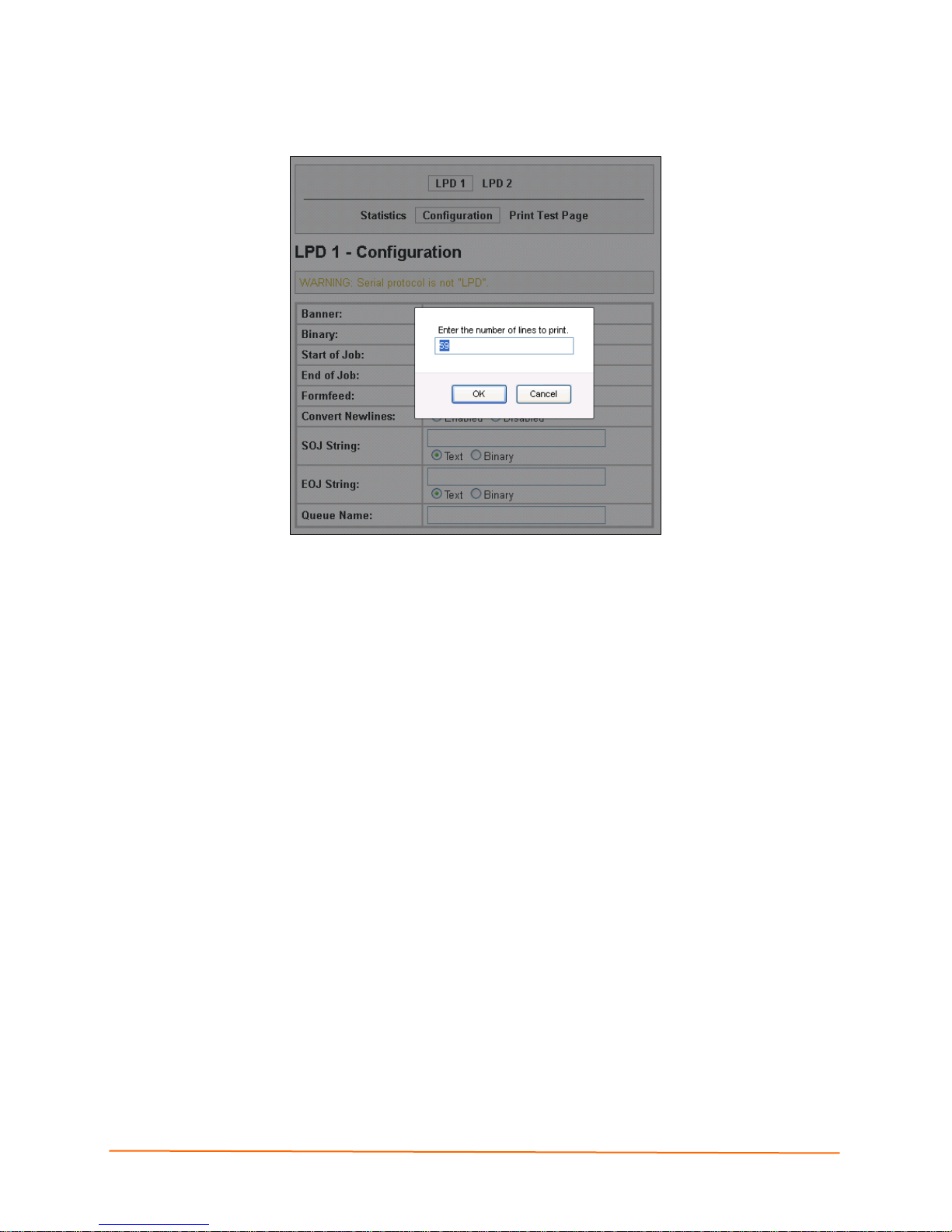
Figure 9-15 LPD Print Test Page
9: Services Settings
To print an LPD test page
1. Enter the number of lines to print.
2. Click the OK button.
IntelliBox-I/O 2100 User Guide 93
Page 94

10: Security Settings
SSH Pages
Clicking the SSH link in the menu bar displays the SSH Server: Host Keys page. This
page has four links at the top for viewing and changing SSH server host keys, SSH
server authorized keys, SSH client known hosts, and SSH client users.
Note: For more information, see SSH.
SSH Server: Host Keys Page
The SSH Server: Host Keys page displays when you click SSH in the menu bar. It also
displays when you click SSH Server: Host Keys at the top of one of the other SSH
pages. Here you can create new keys and upload them to an SSH server.
SSH server private and public host keys are used by all applications that play the role of
an SSH server, specifically the CLI and tunneling in Accept Mode. These keys can be
created elsewhere and uploaded to the device, or automatically generated on the device.
Under Current Configuration, Public RSA Key and Public DSA Key have View and
Delete links if these keys have been created. If you click View, the key displays. If you
click Delete, a message asks whether you are sure you want to delete this information.
Click OK to proceed or Cancel to cancel the operation.
IntelliBox-I/O 2100 User Guide 94
Page 95

Figure 10-1 SSH Server: Host Keys Page
10: Security Settings
IntelliBox-I/O 2100 User Guide 95
Page 96

Table 10-1 SSH Server: Host Keys Page
10: Security Settings
SSH Server: Host
Description
Keys Page Settings
Upload Keys
Private Key Enter the path and name of the existing private key you want to
Public Key Enter the path and name of the existing public key you want to
Key Type Select a key type to be used. Choices are:
Create New Keys
Key Type Select a key type to be used for the new key. Choices are:
Bit Size Select a bit length for the new key. Choices are:
upload or use the Browse button to select the key. Be sure the
private key will not be compromised in transit. This implies the
data is uploaded over some kind of secure private network.
upload or use the Browse button to select the key.
RSA = use this key with SSH1 and SSH2 protocols.
DSA = use this key with the SSH2 protocol.
RSA = use this key with the SSH1 and SSH2 protocols.
DSA = use this key with the SSH2 protocol.
512
768
1024
Using a larger bit size takes more time to generate the key.
Approximate times are:
10 seconds for a 512-bit RSA key
1 minute for a 768-bit RSA key
2 minutes for a 1024-bit RSA key
2 minutes for a 512-bit DSA key
10 minutes for a 768-bit DSA key
15 minutes for a 1024-bit DSA key
Some SSH clients require RSA host keys to be at least 1024
bits long.
IntelliBox-I/O 2100 User Guide 96
Page 97

10: Security Settings
SSH Client: Known Hosts Page
If you click SSH Client: Known Hosts at the top of one of the SSH pages, the SSH
Client: Known Hosts page displays. Here you can change SSH client settings for known
hosts.
Note: You do not have to complete the fields on this page for communication to
occur. However, completing them adds another layer of security that protects
against Man-In-The-Mid dle (MI TM) attacks.
Figure 10-2 SSH Client: Known Hosts Page
Table 10-2 SSH Client: Known Hosts Page
SSH Client:
Description
Known Hosts
Page Settings
Server Enter the name or IP address of a known host. If you entered a server
name, the name should match the name of the server used as the
Remote Address in Connect Mode tunneling.
Public RSA Key Enter the path and name of the existing public RSA key you want to use
with this known host or use the Browse button to select the key.
Public DSA Key Enter the path and name of the existing public DSA key you want to use
with this known host or use the Browse button to select the key.
IntelliBox-I/O 2100 User Guide 97
Page 98

10: Security Settings
SSH Server: Authorized Users Page
If you click SSH Server: Authorized Users at the top of one of the SSH pages, the SSH
Server: Authorized Users page displays. Here you can change SSH server settings for
authorized users.
SSH Server Authorized Users are accounts on the IntelliBox that can be used to log into
the IntelliBox via SSH. For instance, these accounts can be used to SSH into the CLI or
open an SSH connection to a device port. Every account must have a password.
The user's public keys are optional and only necessary if public key authentication is
wanted. Using public key authentication enables a connection to be made without the
password being asked.
Under Current Configuration, User has a Delete User link, and Public RSA Key and
Public DSA Key have View Key and Delete Key links. If you click a Delete link, a
message asks whether you are sure you want to delete this information. Click OK to
proceed or Cancel to cancel the operation.
Figure 10-3 SSH Server: Authorized Users Page
SSH Server:
Authorized Users
Page Settings
Username Enter the name of the user authorized to access the SSH
Password Enter the password associated with the username.
Public RSA Key Enter the path and name of the existing public RSA key you
Public DSA Key Enter the path and name of the existing public DSA key you
IntelliBox-I/O 2100 User Guide 98
Table 10-3 SSH Server: Authorized Users Page
Description
server.
want to use with this user or use the Browse button to select
the key. If authentication is successful with the key, no
password is required.
want to use with this user or use the Browse button to select
the key. If authentication is successful with the key, no
password is required.
Page 99

SSH Client: Users Page
If you click SSH Client: Users at the top of one of the SSH pages, the SSH Client: Users
page displays. Here you can change SSH client settings for users.
SSH client known hosts are used by all applications that play the role of an SSH client,
specifically tunneling in Connect Mode. At the very least, a password or key pair must be
configured for a user. The keys for public key authentication can be created elsewhere
and uploaded to the device or automatically generated on the device. If uploading
existing keys, be sure the private key will not be compromised in transit. This implies the
data is uploaded over some kind of secure private network.
Note: If you are providing a key by uploading a file, make sure that the key is not
password protected.
10: Security Settings
Figure 10-4 SSH Client: Users Page
IntelliBox-I/O 2100 User Guide 99
Page 100

Table 10-4 SSH Client: Users Page
10: Security Settings
SSH Client: Users
Description
Page Settings
Username Enter the name that the IntelliBox uses to connect to the
SSH client user.
Password Enter the password associated with the username.
Remote Command Enter the command that can be executed remotely. Default
is “shell,” which tells the SSH server to execute a remote
shell upon connection. This command can be changed to
anything the remote host can perform.
Private Key Enter the name of the existing private key you want to use
with this SSH client user. You can either enter the path
and name of the key, or use the Browse button to select
the key.
Public Key Enter the path and name of the existing public key you
want to use with this SSH client user or use the Browse
button to select the key.
Key Type Select the key type to be used. Choices are:
RSA = use this key with the SSH1 and SSH2 protocols.
DSA = use this key with the SSH2 protocol.
Create New Keys
Username Enter the name of the user associated with the new key.
Key Type Select the key type to be used for the new key. Choices
are:
RSA = use this key with the SSH1 and SSH2 protocols.
DSA = use this key with the SSH2 protocol.
Bit Size Select the bit length of the new key. Choices are:
512
768
1024
Using a larger Bit Size takes more time to generate the
key. Approximate times are:
10 seconds for a 512-bit RSA key
1 minute for a 768-bit RSA key
2 minutes for a 1024-bit RSA key
2 minutes for a 512-bit DSA key
10 minutes for a 768-bit DSA key
15 minutes for a 1024-bit DSA key
Some SSH clients require RSA host keys to be at least
1024 bits long.
IntelliBox-I/O 2100 User Guide 100
 Loading...