

Page 1

Application Note
In-Vehicle Installation Guidelines for FOX3-
2G/3G/4G and BOLERO40 Series
Part Number APP-0019
Revision A October 2019
Page 2

In-Vehicle Installation Guidelines for FOX3-2G/3G/4G and BOLERO40 Series 2
Intellectual Property
© 2019 Lantronix, Inc. All rights reserved. No part of the contents of this publication may
be transmitted or reproduced in any form or by any means without the written permission
of Lantronix.
Lantronix is a registered trademark of Lantronix, Inc. in the United States and other
countries.
Patented: www.lantronix.com/legal/patents/; additional patents pending.
All trademarks and trade names are the property of their respective holders.
Contacts
Lantronix, Inc.
7535 Irvine Center Drive, Suite 100
Irvine, CA 92618, USA
Toll Free: 800-526-8766
Phone: 949-453-3990
Fax: 949-453-3995
Technical Support
Online: www.lantronix.com/support
Sales Offices
For a current list of our domestic and international sales offices, go to the Lantronix web
site at www.lantronix.com/about/contact
Disclaimer
All information contained herein is provided “AS IS.” Lantronix undertakes no obligation to
update the information in this publication. Lantronix does not make, and specifically
disclaims, all warranties of any kind (express, implied or otherwise) regarding title, noninfringement, fitness, quality, accuracy, completeness, usefulness, suitability or
performance of the information provided herein. Lantronix shall have no liability
whatsoever to any user for any damages, losses and causes of action (whether in contract
or in tort or otherwise) in connection with the user’s access or usage of any of the
information or content contained herein. The information and specifications contained in
this document are subject to change without notice.
Page 3

In-Vehicle Installation Guidelines for FOX3-2G/3G/4G and BOLERO40 Series 3
Revision History
Date
Rev.
Comments
July 2006
1.0.0
Initial version.
December 2006
1.0.1
Added all applicable devices
January 2007
1.0.2
Replaced Figure 3 by a new one. Added description below this
figure.
February 2007
1.0.3
Added point 12 in chapter Fehler: Verweis nicht gefunden devices are not protected against over-voltage.
November 2007
1.0.4
Added additional information about usage of IGN - pin.
These application notes are adapted to the STEPPIII-UX device.
January 2009
1.0.5
Added additional installation instructions in chapters 1.1 and 3.1.
Added Figure 1 - prior Figures 1, 2 and 3 removed.
Added chapter APPENDIX - Contains the pinout of the vehicle
installation cable for STEPPIII-UX, FOX/-LT, BOLERO-LT and
TANGO55/56/864 devices.
September 2009
1.0.6
Added additional installation instructions when using features of
the built-in 3D acceleration sensor.
December 2009
1.0.7
Made corrections and improvements throughout this document.
Added installation instructions for FOX-LT-IP - see chapter 2.1.1
September 2011
1.0.8
Added a new point (9) in chapter "1.1.1" - to filter electromagnetic
and radio-frequency interferences we recommend to use ferrite
clips at power entry point (see fig. 1).
Added the maximum and the recommended tightening torque
that can be used on the mounting nut on the FOX-LT-IP device.
Read chapter 2.1.1.
December 2011
1.0.9
Added new devices FOX-IN, FOX-EN and BOLERO-LT2.
The name FOX-LT-IP changed by DISCO-B4.
Added a new point in to the chapter 1.1.2 - Metal plates near the
antenna may disturb and attenuate the GSM signal.
Added Figure 4 - Axes of Acceleration Sensitivity for FOX-IN/EN
and BOLERO-LT2.
Page 4

In-Vehicle Installation Guidelines for FOX3-2G/3G/4G and BOLERO40 Series 4
February 2013
1.0.10
Added section 1.1.3 "Device installation order", see page 6.
Added new point in chapter "Importance of connection" - see
point "The installation cable with fuse should not be under
tension".
Added the 3-axis diagram for DISCO-B4 and DISCO-B5MAGNET - see Figure 4.
September 2014
1.0.11
Added FOX3-2G/3G/4G series
December 2018
1.1.11
Added BOLERO40 series
Removed FOX-IN, FOX-EN, BOLERO-LT2 and STEPPIII
Added the pinout of all available cables.
October 2019
A
Initial Lantronix document. Added Lantronix document part
number, logo, contact information, and links.
For the latest revision of this product document, please check our online documentation at
www.lantronix.com/support/documentation.
Page 5

In-Vehicle Installation Guidelines for FOX3-2G/3G/4G and BOLERO40 Series 5
Table of Contents
Introduction ............................................................................................. 6
1.1 Installation guidelines and importance of connection for all Lantronix products ... 6
1.1.1 Importance of connection ...................................................................................6
1.2 Installation guidelines .............................................................................................. 7
1.3 Device installation order .......................................................................................... 8
Installation instructions ............................................................................ 9
1.4 Connection precautions ........................................................................................... 9
1.5 Installing DISCO-B4 ................................................................................................. 11
Additional installation help ..................................................................... 13
1.6 Selecting a location with good reception for AVL devices ..................................... 13
1.7 Install Ignition (Optional) ....................................................................................... 13
1.8 Install additional Inputs/Outputs (Optional) .......................................................... 13
1.9 Perform testing ...................................................................................................... 14
APPENDIX ............................................................................................... 15
1.10 CA31b - Vehicle installation cable for FOX3-2G/3G/4G and BOLERO40 series...... 15
1.11 CA39b - Main port extended vehicle installation cable ......................................... 16
1.12 CA68 - Main port extended vehicle installation cable ........................................... 16
1.13 CA70 - Main port basic vehicle installation cable .................................................. 17
1.14 CA69 – Accessory port cable .................................................................................. 17
1.15 CA71 - Accessory port basic cable .......................................................................... 18
1.16 CA38b - Vehicle installation cable for IOBOX-MINI/CAN/WLAN............................ 18
1.17 CA123 - OBDII cable with IGN as separate wire ..................................................... 19
Documentation ....................................................................................... 20
1.18 Additional documentation & software tools ......................................................... 20
Page 6

In-Vehicle Installation Guidelines for FOX3-2G/3G/4G and BOLERO40 Series 6
INTRODUCTION
This document provides all the necessary information to allow your Lantronix products (e.g. FOX3 vehicle
telematics device) to be properly and safely installed. Before beginning the installation of your product, the
installation technician must read completely these Application notes and the hardware manual of the used
product. Important information contained herein is to prevent damages of the used Lantronix product.
This document is applicable only for the following Lantronix devices:
• FOX3-2G/3G/4G series,
• BOLERO40 series,
• DISCO-B4/GLONASS/B5-MAGNET
This document is only addressed to qualified personnel which are well skilled in electronical/electrical
installation and not addressed to private consumers/end users. The installation, implementing or setting
into operation of the product can only be performed by these qualified personnel.
1.1 Installation guidelines and importance of connection for all Lantronix
products
Read these precautions carefully before installing one of the AVL devices in a vehicle. Proper installation
of the Lantronix products requires the installer to have a good understanding of automotive electronics,
systems and well skilled in electronical/electrical installation. Secure placement or installation is the
owner's responsibility. Lantronix shall not be liable for any accident by improper placement or installation
of devices.
1.1.1 Importance of connection
❖ Before beginning any wiring procedure, be sure you understand the wiring diagram added (see Figure 2)
in this document for your particular model. A summary of hints is also given in this diagram.
❖ Turn car ignition off before making any connection.
❖ Apply power to the Lantronix device only when all connections have been made properly. FIRST complete
all the connections required among the device according to the instructions given in this document and
then FINALLY apply power to the unit by connecting the positive pole (+IN) of the device to a vehicle
(+12V or +24V) power source.
❖ Use a common ground point for all ground wires of the device. Improper grounding can create a fault
current.
❖ Prevent second ground connection path between your Lantronix device and vehicle, which may create
ground loops between your unit and vehicle accessories. These ground loops can damage the device (see
Fig. 2 in this document).
❖ The ground-mounted antennas or the device case may often create a fault current, if improper grounding
is made.
❖ To prevent a second ground path during installing the device, first install the GNSS/GSM antenna, then
connect the negative pole of the device (GND) to the vehicle's battery (-) negative terminal and, when
you are sure that all other connections are properly made, apply power to the device by connecting the
positive pole of the device (+IN) to vehicle battery (+) positive terminal or any other (+12V or +24V)
power source.
Page 7
In-Vehicle Installation Guidelines for FOX3-2G/3G/4G and BOLERO40 Series 7
❖ Depending on the Lantronix product you are using, be careful to select the proper wire length and colour
codes of cable used for installation. For more detailed information, refer to the hardware manual of the
Lantronix product you are using.
❖ To eliminate broadcast signals, reduce electromagnetic interference (EMI) and radio-frequency
interference (RFI) we recommend to use ferrite clips which should be installed at the end of the cable
closest to the AVL device (see figure below).
Figure 1: A ferrite clip is placed on the AVL installation cable for reducing electromagnetic interference during the device operation.
❖ All wires of the cable should be firmly secured. Leaving some slack in the wires or bad wire connections
may cause the connections getting loose due to vibration.
❖ The installation cable with fuse should not be under tension. When connecting the installation cable do
not pull on the wire with fuse, you can damage the fuse or lose the connection. We recommend to fix
the fuse case to prevent getting loose due to vibration.
❖ The range of input voltage that may be applied to the Lantronix AVL devices is from +10.8 V ... +32.0 VDC.
Exceeding these ratings could cause damage to the AVL device. To fulfil the range of operating voltage,
Lantronix recommends using the installation cable with the voltage converter called "KNT100V". This
cable can only be used for the vehicles with 24 VDC voltage sources.
❖ All Lantronix AVL devices are not protected internally against over current. Therefore, for safety reasons
and to eliminate over current, all leading lines on an AVL device, such as Continuous plus (clamp 30) or
Ignition (clamp 15), must be externally protected in the following way: nominal protection value in the
direct line maximally 2A (slow-blow-fuse); nominal protection value in the next superordinate circle
maximally 15A. The CE-conformity of the product is given only under adherence to these electrical
operating conditions. The disregard of these electrical operating conditions leads to an offence against
the EN/IEC 60950-1, particularly against the regulations to the reduction of the fire risk.
❖ Improper wiring can damage the device and the vehicle's wiring system.
❖ Your device installation should be checked periodically to maintain proper operation with your vehicle.
1.2 Installation guidelines
❖ Do not mount the Lantronix device or the antenna connected to the device near the electronic devices
and control systems such as speakers, fan motors or actuators. In particular, devices with internal
antenna react sensitively with interferences on the GPS receiver.
❖ Do not mount the Lantronix device, antenna, or any other item in the deployment path of the airbag
system.
Page 8

In-Vehicle Installation Guidelines for FOX3-2G/3G/4G and BOLERO40 Series 8
❖ Do not cover vehicle instruments and displays with cables connected to the Lantronix device.
❖ Do not mount the external antenna or the Lantronix device with internal antenna on the metal plates as
these may disturb and attenuate the GSM signal.
❖ Do not mount cables, antennas or devices in locations that they may be affected by moving parts (in
particular, pedals with lever, shift linkage, control mechanism for ventilation and actuators, rotating
parts, hand brake lever, steering linkages and so on).
❖ Do not mount the device near the heat exchangers and their channels. These belong to the air
conditioning system and heating. The consequences are often overheating or condensation on
electronics, SIM card etc.
❖ Always ensure that connections are clean, secure and fasten. Never let them loose, convoluted or
unsecured in cavities. These may often get out of place due to the vibrations and touch any moving parts
in the vehicle.
❖ Do not bundle or roll up the excess cable. The produced coil is often the reason for induced voltages that
may affect the GNSS and GSM performances as well as the operating voltage of the device.
❖ Do not place battery-powered devices direct in sunlight or air currents of the heating system. Generally,
batteries operate from -20 °C - +60 °C (discharge range) and 0 °C to +45 °C (charge range).
❖ Some vehicles use glass that contains a thin metallic coating for defrosting or to control solar gain; glass-
mount antennas may NOT function properly when mounted on this type of glass. However, most
manufacturers leave free unprocessed places, mostly centrally, for back fitting of GNSS technology.
❖ Glass mounted antennas should not be mounted in places where the vignettes are fixed. These are often
constructed with metallic inside, which also disrupts GNSS and GSM reception.
1.3 Device installation order
Instructions provided in this section describe the hardware installation of an Lantronix AVL device. It is
recommended that you print this list for reference when installing Lantronix devices. To install a Lantronix
AVL device in a vehicle, follow these steps:
1. Before you connect the wires of the installation cable to the fuse box in the vehicle, plug in the 8-Pin
connector into the device
2. Connect the brown wire (which is the GND) to the GND of the vehicle
3. Connect the blue wire (which is the IGN line) to the ignition of the vehicle and other wires like digital
inputs (if needed)
4. Pins that are not planned for usage can be left open without anything connected to them. Table 1, 2 and
3 in chapter APPENDIX describe the pin functionality for the installation cable on the Lantronix AVL
devices
5. Finally, connect the red wire (which is the Vin) to the external power supply (positive pole)
6. Now turn ON the ignition of the vehicle to start up the AVL device
Page 9

In-Vehicle Installation Guidelines for FOX3-2G/3G/4G and BOLERO40 Series 9
INSTALLATION INSTRUCTIONS
1.4 Connection precautions
Selecting an installation location for an external antenna or device is critical:
If your product comes with an external glass-mounted antenna, then install the GNSS antenna in the vehicle
in the locations that are dry and distanced from sources of extreme heat and where the system can receive
GNSS satellite signals from all directions. During installing the antenna, be sure that the cable is extended
and not rolled up. When rolling up the antenna cables, the induced voltage caused by magnetic field may
effect on GSM and GNSS performances and operating voltage as well.
If you use a ground-mounted antenna, please ensure that the antenna ground does NOT come into contact
with vehicle body. This is recommended to avoid the ground loops, which may occur when there is more
than one ground connection path available.
If your product comes with built-in antenna (e.g. BOLERO40) or you want to use the device with internal
antennas (e.g. FOX3), then install the device in a suitable location that does not interfere with the GNSS/GSM
reception. Do not mount the antenna or devices with internal antennas on the metal plates as these may
disturb and attenuate the GSM signal. When a location is found, then perform the test given in chapter 3.4.
Identifying suitable power sources for the unit is also critical.
Turn car ignition off before making any connection to the AVL device. Check the polarity of the battery
terminals with a voltmeter before connecting any of the Lantronix products in the vehicle. Later on, you have
to identify an electrical ground in the vehicle and it should be used as a common ground point for all ground
wires. Connect the unit ground wire to the identified ground ([-]) negative ground battery terminal or vehicle
chassis, see possibilities for power source connections below) and, only when all other connections are
made, connect the unit power lead (+IN) directly to the vehicle battery (+) positive terminal (12V/24V) by
using a 2A fuse.
Possibilities for power source connections:
A) Power is taken directly from the vehicle battery and the vehicle chassis is used as a common ground:
The vehicle chassis (➋) can be used as a common ground ONLY WHEN your vehicle does not have a main
switch (➊) equipped between the battery negative terminal and the vehicle ground. If this switch is in your
vehicle and you select the vehicle chassis as a common ground, then the external power to the unit will
depend on the position of this switch. For non-battery-powered units, the unit is powered OFF, once this
switch is OFF.
B) Power supply pins are connected directly to the vehicle battery:
The battery negative (-) terminal can be used as a common ground ONLY WHEN no second ground occurs.
When an electronic accessory in-vehicle (e.g. radio, cool box and so on) uses the body of the vehicle for
ground, and the device ground pin is directly connected to the battery negative (-) terminal, this can form a
common return path if the antenna (➌) or device case comes into contact with vehicle body (Figure below
illustrates such ground-loops). In such cases, some vehicle accessories can limit the amount of ground that
other accessories can receive. This is commonly known as a ground loop. In other words, a ground loop is an
unwanted electric current path in a circuit resulting in interference, when two grounded points in the same
circuit have different potentials. To prevent such ground loops, it is recommended to shield your device and
the antenna so that no second ground occurs. Additionally, the device positive lead (+IN pin) must be
protected by using a 2A fuse. Most vehicle manufacturers recommend that when both leads (positive and
Page 10

In-Vehicle Installation Guidelines for FOX3-2G/3G/4G and BOLERO40 Series 10
negative) go directly to the battery, they need to be fused (refer to the manufacturer’s installation guidelines
manual for the vehicle).
Figure 2: Power supply pins are connected directly to the vehicle battery. The unit case, antenna and cables are electrically
shielded to avoid ground loops (in the diagram are shown in the green color).
The latest vehicles are equipped with a shunt circuit protection between vehicle battery and vehicle fuse box
allowing the measurement of sink current values flowing through it. Normally, when the vehicle ignition is
turned off, just a small current is drawn from the battery - less than 50 mA. That means, if the power pin
(+IN) is connected behind the shunt circuit, the installed Lantronix device will not be able to draw current
from the vehicle battery while the vehicle is off, as the shunt limits the current flowing through it. Therefore,
it is recommended to install one of Lantronix devices in front of the shunt, as shown in the Fig.2 above.
According to your application requirements, several power sources may be required:
❖ The input supply voltage must provide continuous 12V/24V power and must be able to supply sufficient
current even when the vehicle is off.
❖ Voltage on the ignition pin should be 12V/24V when the vehicle is on, and 0V when it is off (for ignition
controlled application).
❖ To get input changes events, the voltage on an input pin should be 12V/24V for high and 0 V for low.
Using a voltmeter to test for these conditions will help to ensure a successful installation. During this time,
ensure that all vehicle accessories (radio, lights, air conditioning, etc.) are turned off.
If the IGN-pin is not used to control the vehicle ignition states, then it is recommended to connect it to the
operating voltage (+IN) to use the IGN - Sleep mode. With the help of an external switch this will wake up
the device from IGN - Sleep mode (with a HIGH signal on this pin).
Page 11

In-Vehicle Installation Guidelines for FOX3-2G/3G/4G and BOLERO40 Series 11
Additional installation instructions when using features of the built-in 3D acceleration sensor:
To use the features of the built-in 3D acceleration sensor, please ensure:
1. The device should be accurately installed on any flat surface that is parallel to the horizontal axis of
your vehicle with the 16pin connector (for FOX3) or antenna cables pointing to the driving direction.
2. The device should be secured to the vehicle so that no false events can be occurred.
3. The device should be configured by additional alarms to fully use this feature. The force value that
you will enter in the configuration should correspond to the value that your application requires.
4. The value in the configuration should be entered without commas or points (e.g. 1500).
Figure 3: Direction of the detectable accelerations FOX3-2G/3G/4G and BOLERO40 series
Please note that, the pictures below shows that the Z-axis are vertical and pointing up (positive up) and the
X- and Y-axes lie on a horizontal plane. The arrows show always positive values.
1.5 Installing DISCO-B4
The DISCO-B4 contained in a PA6 plastic weatherproof enclosure is designed for mounting on an exterior flat
surface of a vehicle such as the roof. After you have inserted the SIM card inside the device and the casing is
completely water-sealed, then you can install your device on the vehicle's roof or somewhere else on the flat
surfaces. The DISCO-B4 device can be installed in various ways. The following figure gives an example of a
typical installation variant. Before you start the installation, ask for professional advice on the mounting that
would best suit your needs.
To install the DISCO-B4, follow the steps listed below:
✓ Place the six rubber feet into the six spacers of the device.
✓ Installing of the DISCO-B4 requires drilling to your vehicle roof in order to bolt them on. To avoid keeping
the device in direct contact to the sunlight that leads to overheating, it is recommended to mount the
DISCO-B4 device behind the air deflector on your truck roof. Therefore, locate the mounting place and
drill a 32 mm (±0.1mm) hole in the vehicle roof. The device should be placed away from other installed
devices that may obstruct the line of sight between the device and the satellites.
✓ First loosen the mounting nut on the device's bottom side and take it out of cable.
✓ Pass the cables through the hole and then place the device on the mounting surface. The rubber feet
must make full contact with the vehicle's metal roof.
✓ Pass the cable in the nut and then tighten the mounting nut until movement is blocked. The maximum
tightening torque used on the mounting nut must not exceed the maximum value of 12 Nm,
recommended 10 Nm.
Page 12

In-Vehicle Installation Guidelines for FOX3-2G/3G/4G and BOLERO40 Series 12
✓ Make sure the top surface of the device is pointing upwards when tightening the mounting nut (see
example in diagram below).
✓ Finally, connect the vehicle installation cable to the 8pin connector on the external cable of the DISCO-
B4.
✓ Another mount option is to use 6 x hex cap screws M4x30 or longer (not included) - as shown on the
right side of the figure below (second mounting option). For this mount option, refer to the DISCO-B4
Hardware Manual and find out the dimensions of housing.
Figure 5: Mounting the DISCO-B4 on the vehicle's roof
The pin out of the 8pin connector at the end of the cable is given in chapter 4.1.
Page 13

In-Vehicle Installation Guidelines for FOX3-2G/3G/4G and BOLERO40 Series 13
ADDITIONAL INSTALLATION HELP
1.6 Selecting a location with good reception for AVL devices
The unit (e.g. FOX3-2G/3G/4G or BOLERO40 series) should be affixed to:
✓ a dry solid surface,
✓ not exposed to extreme heat,
✓ free from extreme vibration.
The antenna should be placed in a location where:
✓ valid GNSS fix could be obtained,
✓ not covered or blocked by metal,
✓ not near electronic management and control systems,
✓ all connection points to the vehicle are easily accessible (by the user).
Good mounting locations can often be found:
✓ on the windscreen (not for battery-powered devices),
✓ under the vehicle’s dashboard,
✓ under the seats,
✓ on the underside of the rear windshield deck in passenger cars.
1.7 Install Ignition (Optional)
It is recommended to install the IGN line as shown in Fig.2 above. Ignition-controlled power can often be
found in the vehicle’s fuse box or directly from the vehicle’s ignition system. When testing for ignitioncontrolled power, ensure that your power source remains at 12V/24V when the ignition of vehicle is on.
Connect the ignition wire from the unit’s power cable to the ignition-controlled source protected with a 2A
fuse. The ignition input can also be used for journey START and STOP reports (programmable in the software).
The pinout of the vehicle installation cable for FOX3-2G/3G/4G or BLERO40 series is given in chapter Error! R
eference source not found..
1.8 Install additional Inputs/Outputs (Optional)
The inputs provided on the FOX3-2G/3G/4G or BOLERO40 series are high active and will sense a voltage
change between low (ground) and high (12V/24V). This can be done by installing a push button between the
digital input and 12V/24V. Push buttons are open by default, and when the button is pressed the switch
closes to 12V/24V. When the push button is closed (12V/24V) the input changes its state from low to high
and the internal software generates the rising edge event. Similarly, when the push button is opened
(grounded), the input changes its state and the unit generates the opposite falling edge event. These events
can then be programmed in the internal software to execute different alarms or activate e.g. a siren mounted
in the car via a digital output. The provided outputs can be used to control external devices, usually a relay.
For more details, refer to the hardware manual of your device.
Page 14

In-Vehicle Installation Guidelines for FOX3-2G/3G/4G and BOLERO40 Series 14
1.9 Perform testing
The test should be performed with vehicle in an open area where GNSS signal is available. When performing
the initial test, follow the steps listed below:
Make sure all electrical connections including grounding are properly done.
Turn the device on and check its behaviors whether there is sufficient GNSS and GSM reception using
Workbench software. You may also configure 4 alarms to show the GNSS and GSM operation via LED
indicators. See examples below.
Example
PFAL,Cnf.Set,AL1=GSM.GPRS.eConnected:IO12.Set=high
PFAL,Cnf.Set,AL2=GSM.GPRS.eDisconnected:IO12.Set=low
PFAL,Cnf.Set,AL3=GPS.Nav.eFix=valid:IO13.Set=high
PFAL,Cnf.Set,AL4=GPS.Nav.eFix=invalid:IO13.Set=low
If you see that there is sufficient GNSS and GSM reception (note that, acquiring of initial GNSS fix may take
more than 2 minutes), turn on your vehicle and check again if any of vehicle's electronics is causing
interferences to the device. If the device could not obtain a fix within 5-20 minutes, then change the
mounting location of the device and restart the test.
If no interferences are detected and the device gets a fix, then perform the same test during driving, to
check if the GNSS fix stays stable and the device is able to get a valid fix even when the GNSS fix is lost.
When the mounting location has been determined and the test has been successfully completed, turn off
your device and your vehicle and perform the complete installation by keeping in mind the instructions
given in chapter 1.1.
After the device has been mounted, refer to the Getting Started Guide to perform an end-to-end system
test.
Page 15

In-Vehicle Installation Guidelines for FOX3-2G/3G/4G and BOLERO40 Series 15
APPENDIX
1.10 CA31b - Vehicle installation cable for FOX3-2G/3G/4G and BOLERO40
series
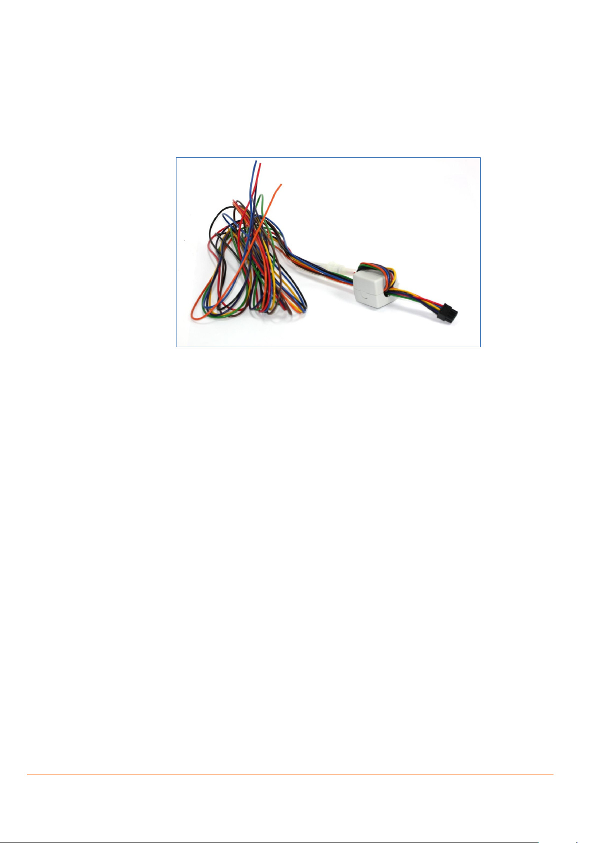
Main port extended installation cable with 8pin (2x4) connector, 4pin (2x2) UCOM connector, 2A-blade-fuse
and open ends.
The pin function, wire assignments and colour codes on the vehicle installation cable for FOX-2G/3G/4G and
BOLERO40 series is listed in table below:
PIN
COLOR
FUNCTION
I/O
DESCRIPTION
1
Red
+IN I INPUT, V+IN = + 10.8 ... + 32.0 VDC; Imax ≤ 2A
2
Brown
GND -
3
Blue
IGN I INPUT HIGH ≥+10.8 .. +32.0 V DC; LOW = 0V
(It can be used to wake up the device from IGN sleep)
4
Orange
I/O1
I/O
Free configurable Input / Output pins.
Digital OUT: 100 mA max. @ +0 .. +32.0V DC
Digital IN: 0 V..+32.0V DC (High & Low = free-programmable)
Analog IN: Up to 32.0 V DC/10 bits resolution
(I/O1 can be used to wake up the device from AiWu sleep)
5
Yellow
I/O2
I/O
6
Green
I/O3
I/O
7
Violette
RxA_0
I
Serial port (receive data) for direct connection to the host PC. If this pin is not used
leave it open. INPUT; V24, ±12 V
8
Black
TxA_0
O
Serial port (transmit data) for direct connection to the host PC. If not used leave it
open. OUTPUT; V24, ±12 V
Table 1: CA31b - Vehicle installation cable pinout
Page 16
In-Vehicle Installation Guidelines for FOX3-2G/3G/4G and BOLERO40 Series 16
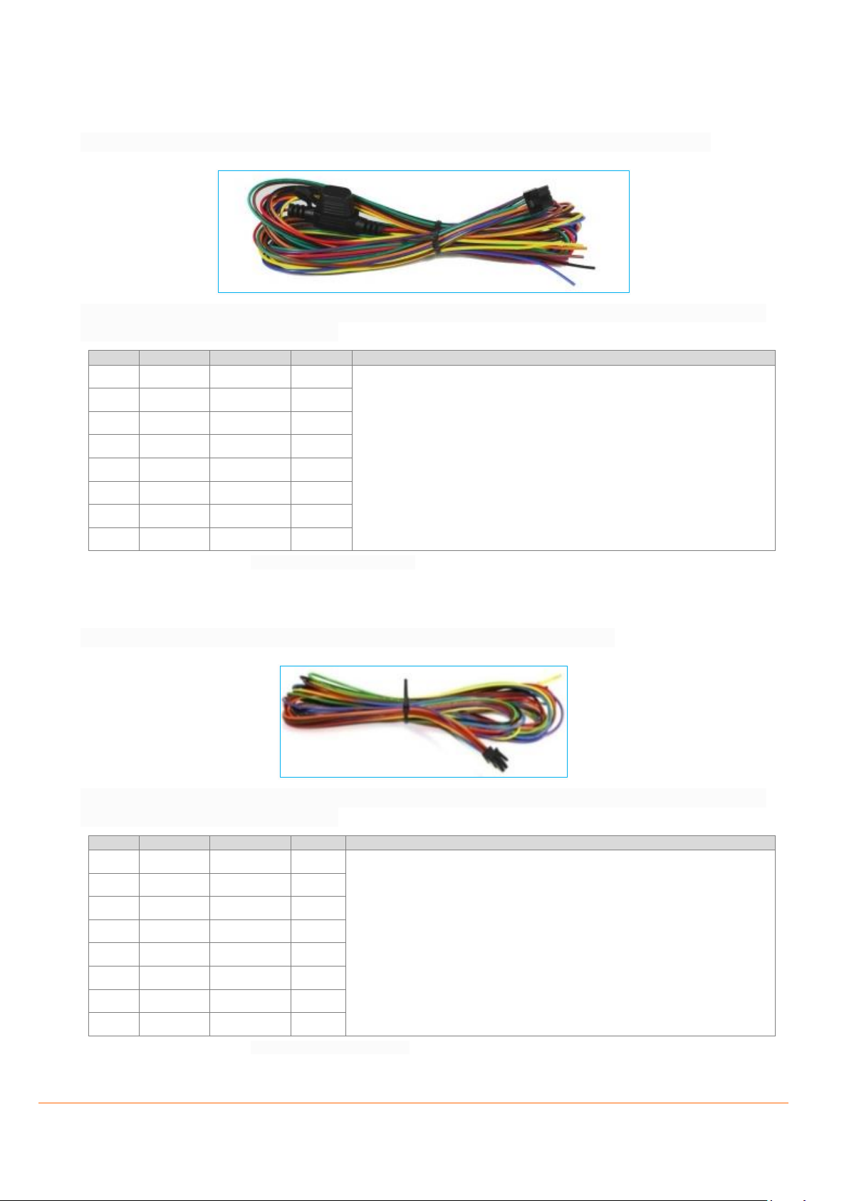
1.11 CA39b - Main port extended vehicle installation cable
The main port extended installation cable with 8pin (2x4) connector, 2A-blade-fuse and open ends.
The pin function, wire assignments and colour codes on the vehicle installation cable for FOX-2G/3G/4G and
BOLERO40 series is listed in table below:
PIN
COLOR
FUNCTION
I/O
DESCRIPTION
1
Red
+IN
I
See description in Table 1
2
Brown
GND - 3
Blue
IGN I 4
Orange
I/O1
I/O
5
Yellow
I/O2
I/O
6
Green
I/O3
I/O
7
Violette
RxA_0
I
8
Black
TxA_0
O
Table 2: Description of cable CA39b
1.12 CA68 - Main port extended vehicle installation cable
The main port extended installation cable with 8pin (2x4) connector and open ends.
The pin function, wire assignments and colour codes on the vehicle installation cable for FOX-2G/3G/4G and
BOLERO40 series is listed in table below:
PIN
COLOR
FUNCTION
I/O
DESCRIPTION
1
Red
+IN
I
See description in Table 1
2
Brown
GND
-
3
Blue
IGN
I
4
Orange
I/O1
I/O
5
Yellow
I/O2
I/O
6
Green
I/O3
I/O
7
Violette
RxA_0
I
8
Black
TxA_0
O
Table 3: Description of cable CA68
Page 17
In-Vehicle Installation Guidelines for FOX3-2G/3G/4G and BOLERO40 Series 17
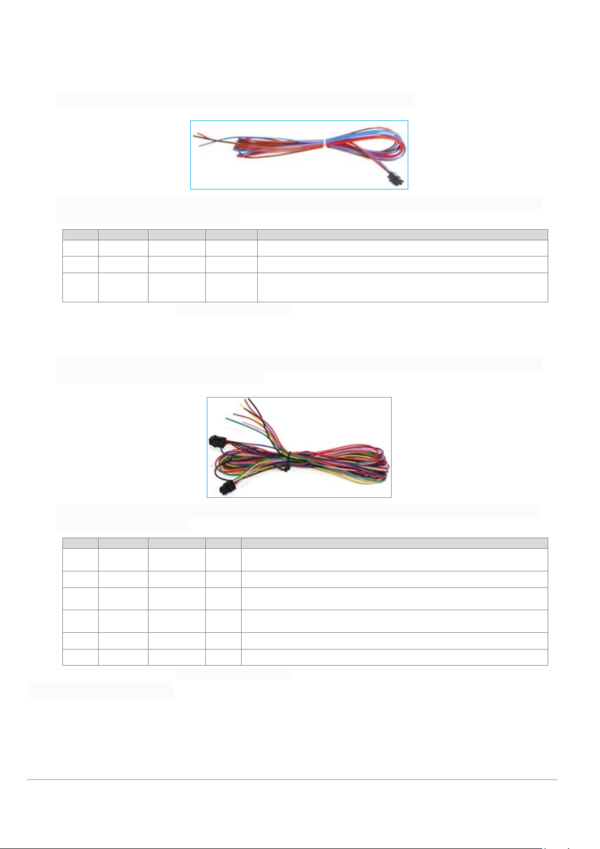
1.13 CA70 - Main port basic vehicle installation cable
The main port basic installation cable with 3pin (2x4) connector and open ends.
The pin function, wire assignments and colour codes on the vehicle installation cable for FOX-2G/3G/4G and
BOLERO40 series is listed in table below:
PIN
COLOR
FUNCTION
I/O
DESCRIPTION
1
Pink
+IN I INPUT, V+IN = + 10.8 ... + 32.0 VDC; Imax ≤ 2A
2
Brown
GND -
3
Violette
IGN I INPUT HIGH ≥+10.8 .. +32.0 V DC; LOW = 0V
(It can be used to wake up the device from IGN sleep)
Table 4: Description of cable CA70
1.14 CA69 – Accessory port cable
The accessory port cable with 6pin (2x3) connector, 4pin (2x2) UCOM connector and open ends can be used
for FOX3-2G/3G/4G series (excl. LITE models).
The pin function, wire assignments and colour codes on the vehicle installation cable for FOX-2G/3G/4G
series is listed in table below:
PIN
COLOR
FUNCTION
I/O
DESCRIPTION
1
Pink
1-Wire
I/O
1-Wire master interface for Driver ID, temperature and humidity sensors. VOUT
= + 2.8 .. +5.0 V
2
Brown
GND
-
Ground Reference.
3
Violette
RxA_1
I
Serial port 1 (receive data) for direct connection to the host PC. If not used leave
it open. V24, ±12 V
4
Black
TxA_1
O
Serial port 1 (transmit data) for direct connection to the host PC. If not used
leave it open. V24, ±12 V
5
Yellow
SCL (I²C)
O
Not supported
6
Green
SDA (I²C)
I/O
Not supported
Table 5: Description of cable CA69
Page 18
In-Vehicle Installation Guidelines for FOX3-2G/3G/4G and BOLERO40 Series 18
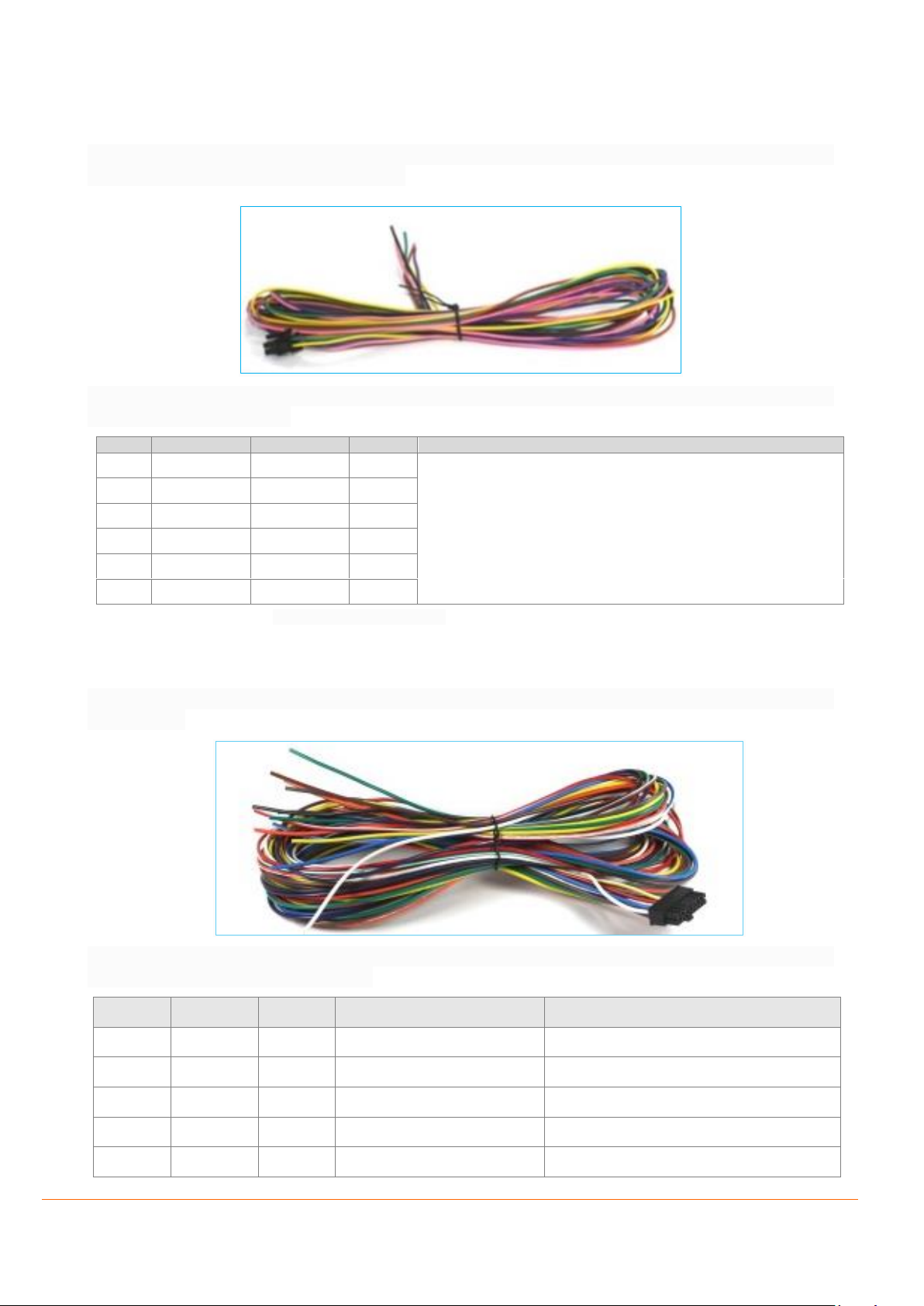
1.15 CA71 - Accessory port basic cable
The accessory port cable with 6pin (2x3) connector, 4pin (2x2) UCOM connector and open ends can be used
for FOX3-2G/3G/4G series (excl. LITE models).
The pin function, wire assignments and colour codes on the vehicle installation cable for FOX-2G/3G/4G
series is listed in table below:
PIN
COLOR
FUNCTION
I/O
DESCRIPTION
1
Pink
1-Wire
I/O
See description in Table 5
2
Brown
GND
-
3
Violette
RxA_1
I
4
Black
TxA_1
O 5 Yellow
SCL (I²C)
O
6
green
SDA (I²C)
I/O
Table 6: Description of cable CA71
1.16 CA38b - Vehicle installation cable for IOBOX-MINI/CAN/WLAN
The automotive connection cable with 16pin (2x8) connector and open ends for IOBOX-MINI, IOBOX-CAN or
IOBOX-WLAN.
The pin function, wire assignments and colour codes on the vehicle installation cable for IOBOXMINI/CAN/WKAN is listed in table below:
PIN
NAME
I/O
DESCRIPTION
LEVEL
1
GND - Ground.
0 V 2 IN5 I Digital input.
0 .. +32.0 V DC (V+IN = +IN)
3 - -
No function
- 4 IN6 I Digital input.
0 .. +32.0 V DC (V+IN = +IN)
5 - -
No function
-
Page 19
In-Vehicle Installation Guidelines for FOX3-2G/3G/4G and BOLERO40 Series 19
PIN
NAME
I/O
DESCRIPTION
LEVEL
6
IN7 I Digital input.
0 .. +32.0 V DC (V+IN = +IN)
7
ANA I Analogue input with 10 bits resolution
0 .. +32.0V DC
8
IN0 I Digital input.
0 .. +32.0 V DC (V+IN = +IN)
9
OUT0
O
Open collector output *
100 mA max. @ 0 .. +32.0V DC
10
IN1 I Digital input.
0 .. +32.0 V DC (V+IN = +IN)
11
OUT1
O
Open collector output *
100 mA max. @ 0 .. +32.0V DC
12
IN2 I Digital input.
0 .. +32.0 V DC (V+IN = +IN)
13
OUT3
O
Open collector output *
100 mA max. @ 0 .. +32.0V DC
14
IN3 I Digital input.
0 .. +32.0 V DC (V+IN = +IN)
15
OUT2
O
Open collector output *
100 mA max. @ 0 .. +32.0V DC
16
IN4 I Digital input.
0 .. +32.0 V DC (V+IN = +IN)
Table 7: Description of cable CA38b
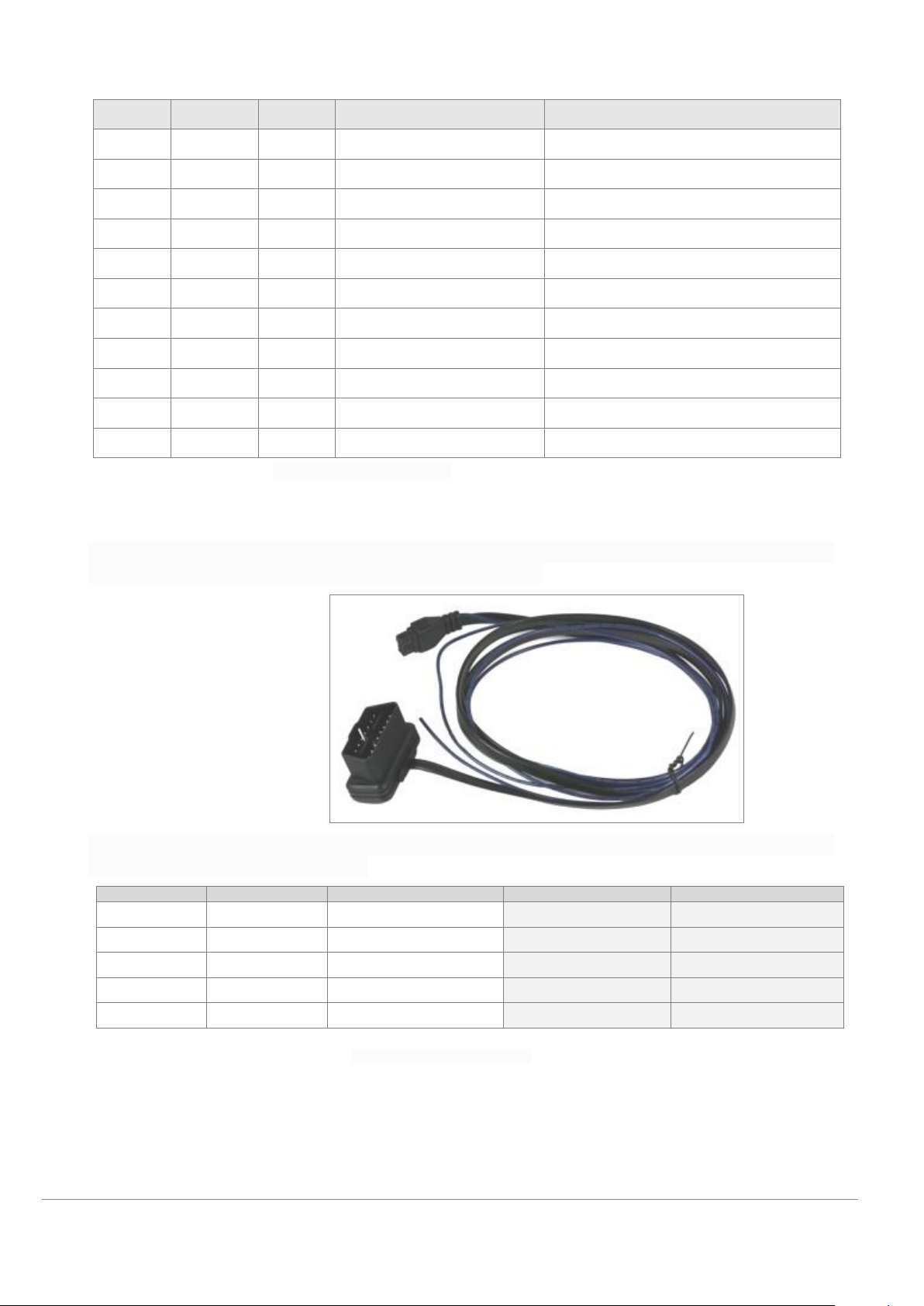
1.17 CA123 - OBDII cable with IGN as separate wire
2x4 MICROFIT to OBDII cable with IGN as separate wire. This cable allows you to apply power to the FOX32G/3G/4G series and BOLERO40 from your car’s OBDII connector.
The pin function, wire assignments and colour codes on the vehicle installation cable for FOX-2G/3G/4G and
BOLERO40 series is listed in table below:
Table 8: Description of cable CA123
2x4 MICROFIT
OBDII connector
Description
FOX3-2G/3G/4G
BOLERO40
2 5 GND
6 6 CAN_High
-
5
14
CAN_Low
-
1
16
V+
3
NC
IGN as separate wire
Page 20

In-Vehicle Installation Guidelines for FOX3-2G/3G/4G and BOLERO40 Series 20
DOCUMENTATION
1.18 Additional documentation & software tools
If this application note does not cover all the information you need to setup, refer to the additional
documents listed below, which can be found on the Product Index or Application Notes pages.
Filename
Description
AVL_PFAL_Configuration_Command_Set.pdf
Lists and describes all PFAL commands supported by the AVL devices.
FOX3_3G_4G_HardwareManual.pdf
Contains instructions for safety and operation of the FOX3-2G/3G/4G devices.
Workbench Software
Description
Lantronix Workbench
Lantronix Workbench configuration tool (Windows XP, Windows Vista, Windows
7 32 bit)
 Loading...