

Page 1

Print Server Installation Guide
For EPS2-100 and EPS4-100 Fast Ethernet Print Servers
Part Number 900-190
Rev. C 1/08
Page 2

Copyright and Trademark
©2002, 2007 Lantronix. All rights reserved. No part of the contents of this book may be transmitted or reproduced
in any form or by any means without the written permission of Lantronix. Printed in the United States of America.
Ethernet is a trademark of XEROX Corporation. UNIX is a registered trademark of The Open Group. Windows
95, Windows 98, Windows 2000, and Windows NT are trademarks of Microsoft Corp. Netscape is a trademark of
Netscape Communications Corporation.
Lantronix
15353 Barranca Parkway
Irvine, CA 92618
USA Phone: 949-453-3990 Fax: 949-453-3995
Technical Support
Online: www.lantronix.com/support
Page 3

Contents
Print Server Installation Guide
1 Introduction
2 Installation
3 Getting Started
4 TCP/IP Configuration
5 NetWare Configuration
6 LAT Configuration
7 AppleTalk Configuration
8 LAN Manager/DLC Configuration
A Contact Information
B Troubleshooting
CPinouts
D Updating Software
E Specifications
F Frequently-used Commands
Warranty Statement
i
Page 4

Declaration of Conformity
Index
Page 5

Introduction
1 - Introduction
The Lantronix multi-port Fast Ethernet Print Servers (EPS2-100 and EPS4-100) are multiprotocol
print servers that provide shared network access to printers for a variety of network protocols and
operating systems. The EPS2-100 and EPS4-100 support the AppleTalk (EtherTalk), LAN
Manager, Local Area Transport (LAT), IPX (NetWare), and TCP/IP protocols. Both servers queue
multiple pending jobs and service those jobs in the order that they are received from the hosts.
NOTE: In this manual, both the EPS2-100 and the EPS4-100 servers will be
referred to as the EPS or as the Server unless a distinction needs to be
made between the models.
1 - 1
Page 6

Introduction
1.1 How to Use This Manual
This guide is structured as follows:
Chapter 2, Installation, explains how to physically install the Server.
Chapter 3, Getting Started, explains the minimum configuration needed to operate the
Server.
Chapters 4 through 8 cover protocol-specific setup needed to install print queues and
otherwise use the Server.
Read chapters 2 and 3 in order, then proceed to the protocol-specific chapter that relates to your
network.
1 - 2
Page 7
Installation
2 - Installation
2.1 Product Description
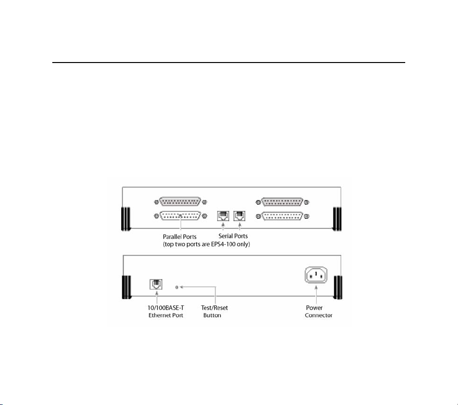
The front panel of the EPS has two RJ45 ports and either two DB25 ports (EPS2-100) or 4 DB25
ports (EPS4-100). The back panel of the EPS has one 10/100BASE-T port, a Test/Reset button,
and a power plug.
Figure 2-1: The EPS Front and Back
2 - 1
Page 8
Installation
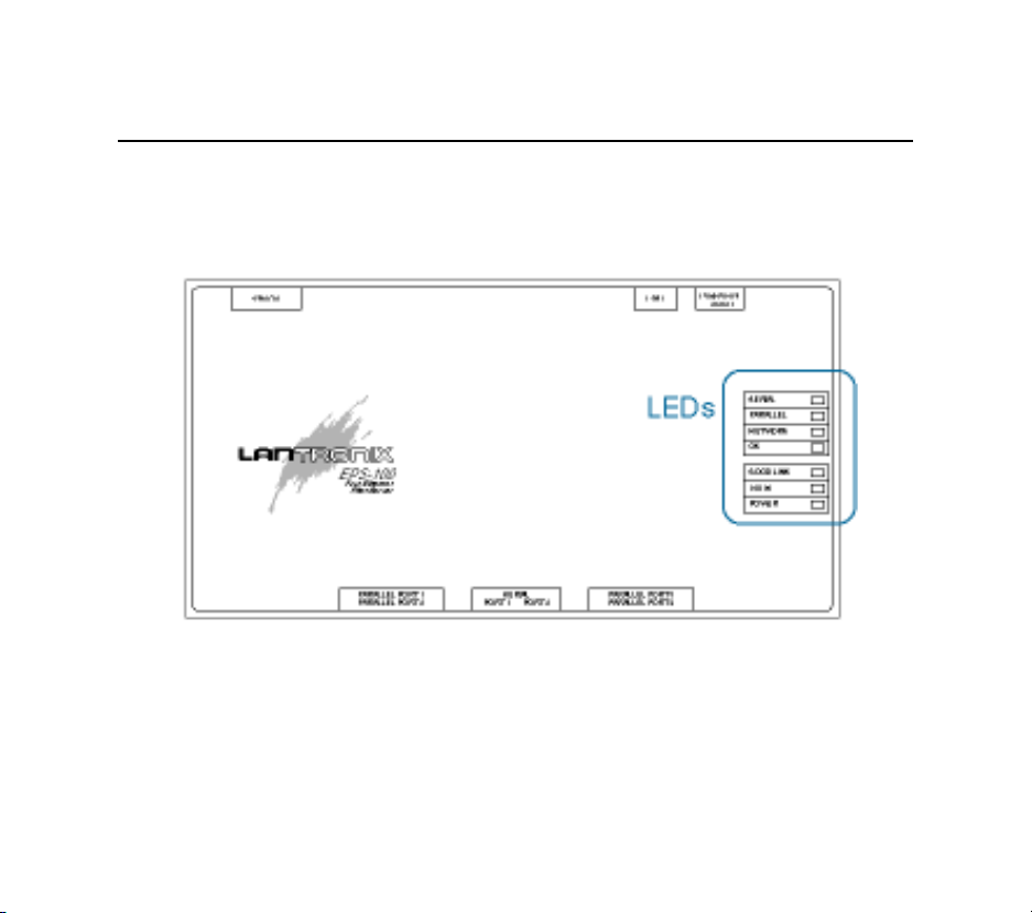
The EPS has 7 LEDs on the top panel
Figure 2-2: EPS LED Location
LED functionality is explained in Table 2-1.
LEDs
2 - 2
Page 9

Installation
Table 2-1: LED Functionality
LED Function During Normal Operation
SERIAL Blinks yellow to indicate serial port activity.
PARALLEL Blinks yellow to indicate parallel port activity.
NETWORK Blinks yellow to indicate Ethernet activity.
OK Lights green (blinks occasionally) to indicate the unit is functioning properly.
GOOD LINK Lights solid green to indicate a working Ethernet connection (either 10BASE-T or
100BASE-T).
10/100 Lights solid green to indicate a 100BASE-T Ethernet connection. If the other LEDs
are functioning normally and this LED is not lit, it means that the connected
network is 10BASE-T.
POWER Lights solid green to indicate that the unit has power.
2 - 3
Page 10
Installation
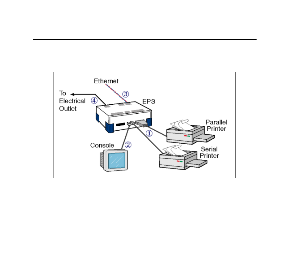
2.2 Installation
The following diagram shows a properly-installed EPS.
To install the server, complete the following steps in order. Refer to the numbers in the figure for
help.
2 - 4
Page 11

Installation
1. Connect at least one printer to the EPS using an available serial or parallel port.
2. If desired, connect a terminal to port 1 (the console port) to receive diagnostic and initial
configuration messages.
3. Connect the EPS to the 10/100BASE-T network.
NOTE: The default serial port settings are 9600 baud, 8 bit characters, and no parity.
4. Attach one end of the power cable to the EPS; plug the other end into an electrical outlet.
Power will come on automatically.
5. Allow 45 seconds for the unit to fully boot. The OK LED should be lit to show the unit is
functioning properly.
If you have connected a 10BASE-T cable to the Server, the Link LED should be solid
green. If you have connected a 100BASE-T cable, The Link and 100MBit LEDs should
both be solid green. If not, check your network connection.
6. Print a Test page by pressing the Test/Reset button.
NOTE: If the Power LED does not light or the Test page does not print, refer to
Appendix I, Troubleshooting.
7. Install EZWebCon on your 32-bit Windows PC to configure your Server. The EZWebCon
software is located on the CD-ROM. See EZWebCon Configuration on page 3-2 for more
information.
2 - 5
Page 12

Page 13

Getting Started
3 - Getting Started
It is important to consider the following points before logging into and configuring the EPS:
The EPS IP address must be configured before any TCP/IP functionality is available.
(See Setting the IP Address on page 4-2.)
There are two important passwords on the EPS: the privileged password and the login
password.
Changing any server, service, or port setting requires privileged user status. The default privileged password is system.
The login password is required for remote console logins.
The default login password is access.
NOTE: If you would like to change either the privileged or login password,
either use EZWebCon or refer to the Print Server Reference Manual
located on the CD-ROM.
3 - 1
Page 14

Getting Started
3.1 EZWebCon Configuration
The EZWebCon configuration software is the recommended way to configure the EPS.
EZWebCon is a graphical user interface that guides first time users through the initial
configuration process and allows experienced users to update and change any configurable
parameters. There are two important things to note about EZWebCon:
Your Server must have an IP address before EZWebCon can log into it for configura-
tion purposes. See Setting the IP Address on page 4-2 for instructions.
EZWebCon requires a Java Virtual Machine (JVM) on the client. Lantronix provides
JVM installers for Solaris and 32-bit Windows users, as well as source code and
instructions for compiling it for use on other systems.
The EZWebCon software is located on the distribution CD-ROM. All instructions for installing
EZWebCon are provided in the README file. For assistance once EZWebCon is running, refer to
the EZWebCon on-line help.
NOTE: EZWebCon is also available from the Lantronix FTP and BBS servers.
See Appendix D for more information about logging into the FTP and
BBS servers.
3 - 2
Page 15

Getting Started
3.2 Incoming Logins
Incoming logins made via EZWebCon can be used to configure the server. Incoming LAT and
TCP/IP logins can also be used.
Incoming Telnet is enabled by default to allow TCP/IP connections. To change this setting, use
the Define Server Incoming command described in the Command Reference chapter of the Print
Server Reference Manual located on CD-ROM.
Incoming logins do not prompt for a login password; therefore, you may wish to disable them. If
it is undesirable to disable incoming logins, the Server can be configured to prompt for a
password with the Define Server Incoming Password Enabled command.
3.3 Services
With few exceptions, a service must be created before print queues can be configured on the EPS.
A service is a resource accessible to network hosts. A Lantronix service is also known as a remote
printer name or remote queue name on many operating systems.
The EPS
xxxxxx represents the last six numbers of the unit’s Ethernet address and yy is the port name, for
example EPS_xxxxxx_S1 (serial port) or EPS_xxxxxx_P1 (parallel port).
offers a default service on each port. The service names are EPS_xxxxxx_yy where
NOTE: The default service names are based on the server name; therefore the
server name must be no more than 13 characters.
3 - 3
Page 16

Getting Started
The default services on the serial ports have the TCP/IP, NetWare, LAN Manager, and AppleTalk
protocols enabled. Parallel port services have TCP/IP, NetWare, and LAN Manager enabled. LAT
is disabled by default on all services provided by the Server
because many network managers
object to the frequent LAT service announcements. AppleTalk is disabled on parallel port services
because AppleTalk requires Bitronics mode, which is disabled by default.
If you need to modify a default service, use EZWebCon or see the Server Configuration chapter of
the Print Server Reference Manual located on the CD-ROM.
3 - 4
Page 17

TCP/IP Configuration
4 - TCP/IP Configuration
The EZWebCon configuration software is the easiest way to configure the EPS. The following
sections cover IP address configuration and print configuration methods for TCP/IP hosts.
NOTE: The Server needs an IP address before you can use EZWebCon. See
page 4-2 for instructions.
The EPS provides two major methods of printing via TCP/IP: Berkeley remote LPR and RTEL
host software.
Neither Windows for Workgroups nor Windows 95 support LPR directly; however, there are third
party solutions available. For more information about recommended peer-to-peer printing
solutions, see the Lantronix Windows 95 FAQ on the CD-ROM or the Lantronix web site.
4 - 1
Page 18

TCP/IP Configuration
4.1 Setting the IP Address
The EPS IP address must be configured before any TCP/IP functionality is available.
To set the IP address, use one of the following methods: EZWebCon; a directed Ping packet; a
DHCP, BOOTP, or RARP reply; or commands entered at the command line (Local>) interface.
4.1.1 Using EZWebCon
The EPS must have an IP address before you can log into it using EZWebCon. To assign the IP
address from EZWebCon:
1. Start EZWebCon. Instructions for installing, running, and using EZWebCon can be found
on the distribution CD-ROM.
2. Click on the Lantronix logo menu in the bottom left corner of the EZWebCon window,
then select Assign IP Address to Server.
3. Fill in the following information:
A. The last three bytes of the EPS’s hardware address. The hardware address is printed
on the bottom of the Server.
B. The desired IP address.
C. The subnet, if you wish to use a subnet other than the default.
4 - 2
Page 19
TCP/IP Configuration
D. The IP address of the TFTP server you wish to use, if desired.
4. Click OK.
5. Cycle power on the server. EZWebCon will let you know whether the configuration was
successful.
4.1.2 Using a Directed Ping Packet
The ARP/ping method is available under UNIX, Windows 95, and Windows NT. If the EPS has
no IP address, it will set its address from the first directed IP packet it receives.
NOTE: The ARP/ping method only works during the first two minutes of EPS
operation. After two minutes, an alternate method must be used or the
EPS must be rebooted.
On a UNIX host, create an entry in the host’s ARP table and substitute the intended IP address
and the hardware address of the server, then ping the server. This process typically requires
superuser privileges.
# arp -s 192.0.1.228 00:80:a3:xx:xx:xx
% ping 192.0.1.228
4 - 3
Page 20
TCP/IP Configuration
In order for the ARP command to work on Windows, the ARP table on the PC must have at least
one IP address defined other than its own. If the ARP table is empty, the command will return an
error message. Type ARP -A at the DOS command prompt to verify that there is at least one entry
in the ARP table.
If there is no other entry beside the local machine, ping another IP machine on your network to
build the ARP table. This has to be a host other than the machine that you're working on. Once
there is at least one entry in the ARP table, use the following commands to ARP the IP address to
the EPS and make the EPS acknowledge the IP assignment.
C:\ ARP -S 192.0.1.228 00-80-A3-XX-XXXX
C:\ PING 192.0.1.228
NOTE: There should be replies from the IP address if the ARP command
worked.
When the EPS receives the ping packet, it will notice that its IP address is not set and will send out
broadcasts to see if another node is using the specified address. If no duplicate is found, the server
will use the IP address and will respond to the ping packet.
The EPS will not save the learned IP address permanently; this procedure is intended as a
temporary measure to enable EZWebCon to communicate with the server, or allow an
4 - 4
Page 21

TCP/IP Configuration
administrator to Telnet into the EPS. Once logged in, the administrator can enter the Change
IPaddress command to make the address permanent.
% telnet 192.0.1.228
Trying 192.0.1.228
Lantronix Version n.n/n (yymmdd)
Type Help at the ‘Local_>’ prompt for assistance.
Enter Username> gopher
Local> SET PRIVILEGED
Password> system (not echoed)
Local>> DEFINE IPADDRESS 192.0.1.228
Any host wishing to access the EPS will have to be told the EPS’s IP address. This is typically
configured in the unix file /etc/hosts or via a nameserver. Refer to the host’s documentation for
additional information.
4 - 5
Page 22

TCP/IP Configuration
4.1.3 Using a DHCP, BOOTP, or RARP Reply
At boot time a host-based DHCP, BOOTP, or RARP server can respond to an EPS request for an
available IP address. For information about configuring the DHCP, BOOTP, or RARP server, see
your host documentation.
4.1.4 Using the Command Line Interface
1. Connect to the serial port (Port 1) using a terminal emulation program. The serial settings
should be 9600 baud, 8 bits, 1 stop bit, no parity.
2. Become the privileged user and enter the new IP address.
Local> SET PRIVILEGED
Password> system (not echoed)
Local>> DEFINE SERVER IPADDRESS 192.0.1.201
4 - 6
Page 23

TCP/IP Configuration
4.2 Notes About LPR
There are four important things to note about the LPR printing method:
1. Because of the way the LPR protocol is typically implemented on the host, the processing
options and banner page are sent after the job data itself. The EPS will print a banner
page at the end of a job, and cannot support most of the LPR options. If it is necessary
to have the banner page at the beginning of the printout, install and use the RTEL software. If banners are not needed, they can be disabled.
2. The EPS cannot print multiple copies of the print job when using the -#n lpr option.
3. If two print queues on the host refer to two services on the same EPS, they must use separate spooling directories.
4. No special purpose input or output filters can be used when printing via LPR. If this functionality is necessary, use the named pipe interface program in the RTEL print queue configuration software.
4 - 7
Page 24
TCP/IP Configuration
4.3 LPR on Windows NT 4.x
NOTE: This installation assumes that TCP/IP, Simple TCP/IP, and Microsoft
TCP/IP printing have been installed on the Windows NT host.
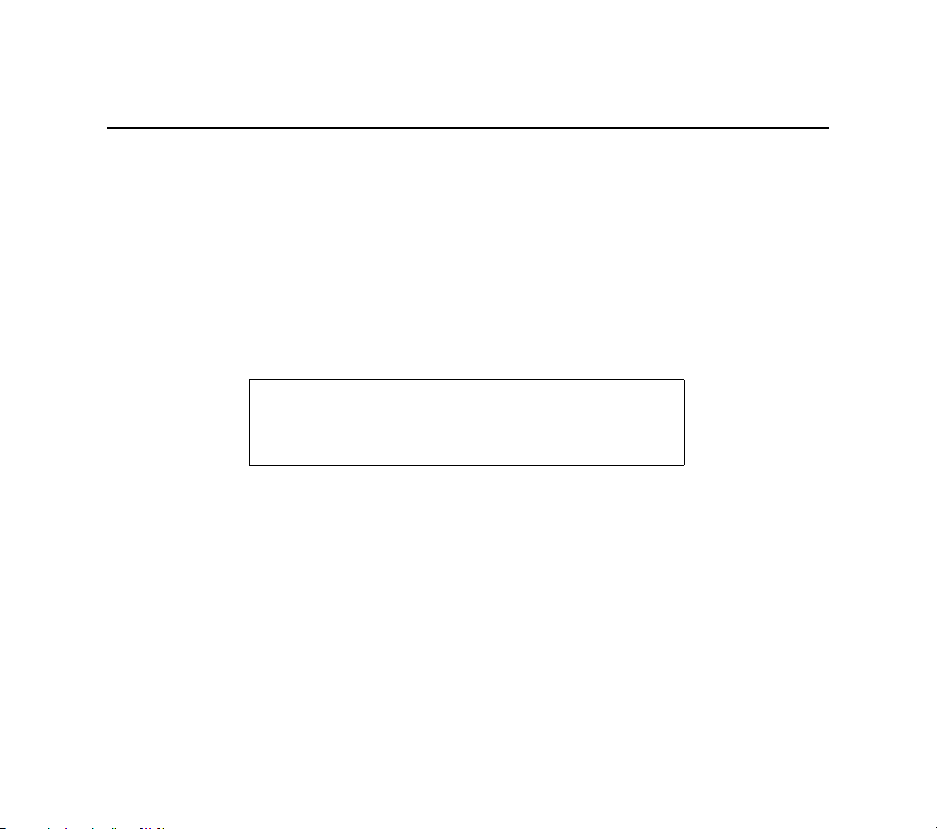
1. In the Control Panel, double-click the Printers icon.
2. Double-click the Add Printer icon.
3. In the window that appears, choose My computer and click Next.
4 - 8
Page 25
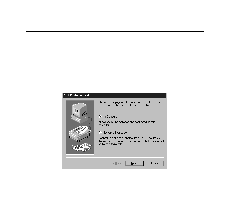
4. Select the Add Port button and click Next.
TCP/IP Configuration
4 - 9
Page 26
TCP/IP Configuration
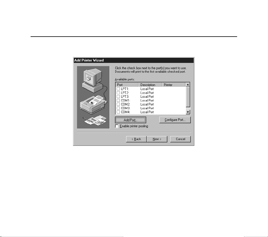
5. Select LPR Port.
NOTE: If LPR Port is not an option, refer to your Windows NT documentation for
instructions on installing the Microsoft TCP/IP Printing service.
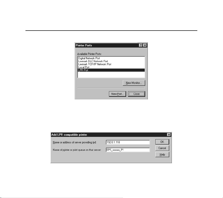
6. Enter the name or IP address of your EPS on the first line, and enter the name of your EPS
print service on the second line.
4 - 10
Page 27
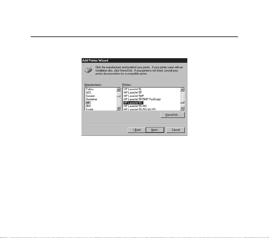
7. Select the manufacturer and printer type.
TCP/IP Configuration
4 - 11
Page 28
TCP/IP Configuration
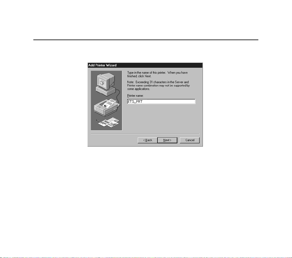
8. Enter the queue name.
4 - 12
Page 29
TCP/IP Configuration
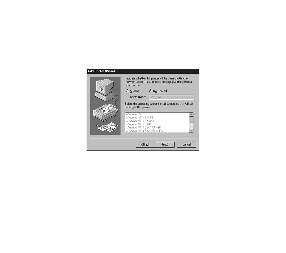
9. If applicable, choose Shared and select the type of operating system that the printer will
be working with. (First confirm that the print queue is working.)
4 - 13
Page 30
TCP/IP Configuration
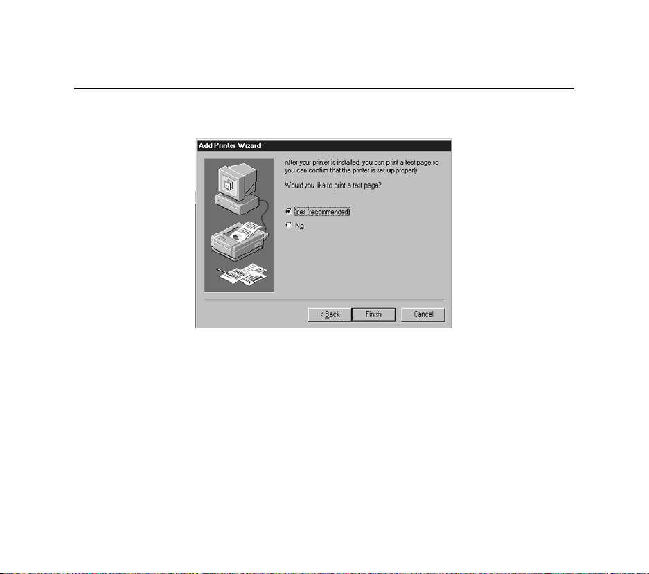
10. Test the printer.
4 - 14
Page 31

TCP/IP Configuration
4.4 LPR on UNIX Hosts
The Berkeley remote printing system is supported on many machines, and is simple to configure.
This section describes how to configure LPR print queues on generic UNIX hosts such as SUN
hosts. There are slight variations in LPR configuration for AIX, HP, and SCO hosts, as will be
explained in the following sections.
1. Install a print queue on your host by adding the EPS name and IP address to the
/etc/hosts file:
192.0.1.88 EPS_xxxxxx
2. Add the host print queue to the /etc/printcap file:
eps_prt|Printer on LAB EPS:\
:rm=EPS_xxxxxx:\
:rp=EPS_xxxxxx_TEXT:\
:sd=/usr/spool/lpd/eps_prt:
The punctuation shown is required, and no extra spaces should be added.
4 - 15
Page 32

TCP/IP Configuration
This will create a host queue named eps_prt. The rm parameter is the name of the EPS in
the host's address file, the rp parameter is the name of the service as it exists on the EPS,
and the sd parameter specifies the name of a directory used to hold temporary spooling files.
3. Create a world-writable spooling directory using the mkdir command.
# mkdir /usr/spool/lpd/eps_prt
# chmod 777 /usr/spool/lpd/eps_prt
4. If desired, use the mx option to allow unlimited size files to be printed and the sh option to
prevent header pages from being generated. See the host's documentation or man pages for
more information on the format of the printcap file and how to create the spool directory.
5. Print to the queue using normal lpr commands:
% lpr -Peps_prt /etc/hosts
4.4.1 LPR on AIX Hosts
LPR has only been tested on AIX versions 3.2 and higher. The System Management Interface
Tool (SMIT) allows you to enable LPD printing and create print queues.
4 - 16
Page 33

TCP/IP Configuration
To create a print queue:
1. At the host prompt type smit.
2. Choose Print Spooling.
3. Choose Manage Print Server and Start the Print Server Subsystem (lpd
daemon).
4. In the Start the Print Server Subsystem dialog box, type both in the first field.
The message The lpd subsystem has been started will appear. Click Done.
To add a print queue:
1. From the main window choose Print Spooling.
2. Choose Manage Print Server and Manage Print Queues.
3. Choose Add a print queue.
4. From the dialog box that appears choose remote.
5. From the next dialog box choose Remote Printing.
6. The Add a Standard Remote Print Queue dialog box will appear. Enter the
following information.
- The name of the print queue,
4 - 17
Page 34

TCP/IP Configuration
- The name of the EPS unit,
- The name of the EPS service,
- The type of print spooler on the remote server, and
- A description of the printer on the remote server.
A dialog box will appear with the message Added print queue eps_prt.
NOTE: If you are unable to use SMIT, see the Print Server Reference Manual
for UNIX commands for setting up print queues.
7. Print to the queue using normal lp syntax.
% lp -deps_prt filename
4 - 18
Page 35

4.4.2 LPR on HP Hosts
The System Administration Manager (SAM) allows you to create print queues.
NOTE: If you are unable to use SAM, the Print Server Reference Manual
located on the CD-ROM described UNIX commands that can be used
to set up print queues.
To create a print queue:
1. At the HP prompt type sam.
2. From the main application window choose Printers and Plotters.
3. Choose Printers/Plotters from the Printers and Plotters window.
4. In the pull-down menu select Remote Printer/Plotter from the Actions menu.
5. The Add Remote Printer window will appear. SAM will prompt you for:
- The printer name (the name of the print queue),
- The remote system name (the EPS name),
- The remote printer name (the EPS service),
- The remote cancel model, and
TCP/IP Configuration
- The remote status model.
4 - 19
Page 36

TCP/IP Configuration
4.4.3 LPR on SCO UNIX Hosts
LPR is supported in SCO V3.2 release 4 with TCP/IP Version 1.2 and greater.
To configure a print queue using LPR:
1. Issue the mkdev rlp command. This will install the Berkeley remote printing files and executable programs.
NOTE: The mkdev rlp command should only be issued once, or serious problems
will occur. If this happens, contact SCO technical support.
You can print to this queue using normal lp syntax once the remote printer is set up.
To create a remote printer:
1. Issue the rlpconf command.
2. Answer the questions that follow. See the figure on the next page for more
information.
4 - 20
Page 37

TCP/IP Configuration
Remote Printing Configuration
Enter information for remote printers or local printers accepting remote
printing requests
Please enter the printer name (q to quit): backupprinter
Is printer backupprinter a remote printer or a local printer? (r/l) r
Please enter the name of the remote host that backupprinter is attached
to: EPS_xxxxxx
The backupprinter is connected to host EPS_xxxxxx.
Is this correct? (y/n) y
Would you like this to be the sys.default printer? (y/n) y
Make sure your hostname appears in EPS_PRT’s /etc/hosts.equivor or /etc/
hosts:lpd file.
Make sure backupprinter appears in /etc/printcap (in BSD format).
Make sure backupprinter has a spool directory on EPS_PRT.
Putting the printer in printer description file and creating spool directory... done
Updating LP information... done
The printer name is your EPS service name. The remote host name is the name of your EPS
as it is listed in your hosts file.
4 - 21
Page 38

TCP/IP Configuration
During initial configuration, the queue name must be the same as the remote printer name.
However, you may change the queue name later by manually editing the printcap file.
4.5 RTEL Functionality
If the LPR method of printing is not adequate for an application (for example, if you need banners
before jobs, or more flexibility), configure the Lantronix-supplied RTEL software on the host.
After installing the software configuring the connections to the EPS, you can use normal UNIX
print commands and queue utilities such as lpc and lpstat.
NOTE: RTEL binaries are provided for many systems. Source code is also
provided for use on non-supported systems.
To print to the EPS using special formatting or using third-party software packages, you may
have to create print pipes on the host. The RTEL software provides this functionality by
providing a UNIX named-pipe interface.
To recreate the RTEL source files:
1. Copy the file RTEL_SRC.TAR from the distribution CD-ROM to the UNIX host. Ensure
that a binary copy is performed.
2. Untar the archive.
4 - 22
Page 39

TCP/IP Configuration
3. See the README files in the created directories that describe the contents of the RTEL
distribution and man pages that describe the actual software functionality.
4.6 Unix Host Troubleshooting
Table 4-1: TCP Troubleshooting
Area to Check Explanation
The Server IP address and name are
entered in the host file
Jobs that appear in the host queue reach
the Server
Telnet to the Server using the name in the host file and
verify that the Server name is resolvable and that the Server
is reachable via the network.
From within the LPC administrative utility, enter these
commands to clear and reset the host queue:
abort queue_name
clear queue_name
enable queue_name
start queue_name.
4 - 23
Page 40

Page 41

NetWare Configuration
5 - NetWare Configuration
The EZWebCon configuration software is the easiest way to configure the EPS. The following
sections cover print configuration methods for NetWare hosts.
NOTE: The Server needs an IP address before you can use EZWebCon. See
the Setting the IP Address section on page 4-2 for instructions.
This chapter explains creating NDS print queues with NetWare Administrator and with the
PCONSOLE Quick Setup option. To create NDS print queues, you must be running NetWare
version 4.x with NDS capabilities.
If you are running NetWare versions 2.x, 3.x, or version 4.x with bindery emulation, you may
configure bindery print queues using QINST (bindery only) or PCONSOLE. For more
information, see the NetWare chapter of the Print Server Reference Manual, located on CD-ROM.
5 - 1
Page 42

NetWare Configuration
5.1 Obtaining an NDS License
If you wish to create NDS print queues, you must read and complete an NDS registration form via
one of the following methods:
Using a forms-capable Internet browser, navigate to the Lantronix World Wide Web
site (located at URL http://www.lantronix.com) and find the NDS Registration link.
Send email to nds-info@lantronix.com. You will receive a blank registration form
that can be completed and returned to Lantronix.
If you don’t have Internet access, contact a Lantronix Technical Support representa-
tive for assistance. Contact information is provided in Appendix A -.
1. License NDS on your server using the string obtained from Lantronix.
Local>> DEFINE PROTOCOL NETWARE DSLICENSE licensestring
2. Define the directory service tree in which the Server is located.
Local>> DEFINE PROTOCOL NETWARE DSTREE foodco
NOTE: For an explanation of the structure of the NetWare Directory Service
5 - 2
Page 43

NetWare Configuration
tree, see your host documentation.
3. Define the directory service context in which the Server is located.
Local>> DEFINE PROTOCOL NETWARE DSCONTEXT ou=kiwi.ou=exotic.o=fruit
4. Enter the List Protocol NetWare Access command to ensure that at least one of the file
servers in the directory service tree is in the access list.
5. If desired file server is not in the access list, add it.
Local>> DEFINE PROTOCOL NETWARE ACCESS fileserver
6. Reboot the EPS.
Local>> INITIALIZE DELAY 0
5.2 Creating Print Queues Using NetWare Administrator Quick Setup
The NetWare Administrator management utility allows you to manage network resources, such as
queue-based print services, in a tree structure. You can either use the Quick Setup option or
individually create printing-related objects.
5 - 3
Page 44

NetWare Configuration
To create a print queue with the Quick Setup option.
NOTE: NetWare Administrator can be used for both NDS and bindery print queues.
1. Start NetWare Administrator.
2. In the Directory Tree windows, select the context in which to install the printer.
3. From the Menu Bar, select Tools: Print Services Quick Setup.
4. In the Print Server Name field, enter the name of your Lantronix server (viewable by
entering the Show Server command at the Local> prompt).
5. In the Printer Name field, enter the name of the desired print service configured on your
Lantronix server.
6. In the Print Queue Name field, enter the name of the print queue to create. The name
should be meaningful to you; it will not affect Server configuration.
7. Click Create.
8. Reboot the EPS.
5 - 4
Page 45

NetWare Configuration
5.3 Creating NDS Print Queues Using PCONSOLE
1. Log in as Admin on the file server you will be changing.
2. Type PCONSOLE at the X: prompt to start the utility.
For example, if your file server is mapped to the F: drive, you would use the F: prompt.
3. From the main menu choose Quick Set-Up.
4. PCONSOLE will prompt you for information with which to configure the print queue.
The print server name is the name of your EPS (EPS_xxxxxx). The new printer name is the
service name (for example, EPS_xxxxxx_Text). The new print queue can be any name. The
print queue volume is the name of the file server from which the printer receives print
requests. The remaining fields can be left in their default settings.
NOTE: In the above text, xxxxxx represents the last 6 digits of your EPS’s
hardware address. The hardware address is printed on the unit’s
label.
5. Press the F10 key to save the print queue information.
6. Reboot the EPS.
5 - 5
Page 46

NetWare Configuration
5.4 NetWare Host Troubleshooting
Table 5-1: NetWare Host Troubleshooting (Bindery Mode)
Area to Check Explanation
The server and queue names in
PCONSOLE match the print server name
and its service name?
The Server’s NetWare access table Use the Show Protocols NetWare Access command.
Use PCONSOLE to check.
Scanning too many file servers can cause a delay between
jobs.Configure the access list to only scan for jobs on the file
servers of interest.
Table 5-2: NetWare Host Troubleshooting (NDS)
Area to Check Explanation
The Server’s NetWare access table Use the Show Protocols NetWare Access command. By
default, only local file servers are scanned for queues.
The login password on the Server and
the queue password on the file server
5 - 6
The passwords must match or the Server will not be able to log
into the file servers to scan for jobs.
Page 47

Table 5-2: NetWare Host Troubleshooting (NDS), cont.
Area to Check Explanation
NetWare Configuration
The print server has successfully
attached to the queue
The DSTree, DSContext, and
DSLicense
Printer and queue changes have
propagated through the NDS tree
Typ e NETSTAT at the Local> prompt. This will display
information about fileservers, printers, and queues that the
print server has found. If a queue is in JobPoll, the print server
has successfully attached to the queue.
Typ e Show Protocol NetWare NDS. This command shows
the tree and the context that you have configured, a failure
code, and an NDS error code for each server.
DSTree is the directory service tree on which the print server is
located. DSContext is the context where the print server is
located; it must match the context on the file server (The
DSContext must be of the following form: ou=fruit.o=exotic).
DSLicensed should be yes.
It may take a few minutes for the changes to propagate. If the
print server doesn’t attach, reboot the server.
5 - 7
Page 48

NetWare Configuration
Table 5-3: NDS Errors from the File Server
Failure code Failure code meaning Remedy
0xfffffda7 Object could not be found in the
given context
0xfffffda5 The requested attribute could not
be found
0xfffffd69 DS Database is locked An administrator is probably updating the database.
0xfffffd63 The password is invalid The password for the print server object under
0xfffffd54 Secure NCP violation Turn down the NCP packet signature level so that it is
Check the print server name, DScontext, and DStree to
make sure that the printer server is set up correctly with
PCONSOLE.
Use PCONSOLE to make sure that the print server has
associated printers and that the printers have associated
queues.
Wait a few minutes and issue the Set Protocol
NetWare Reset command.
PCONSOLE must match the Server’s login password.
If the login password on the Server is left as the default
(access), there should be no password for the print
server object.
not required from the server.
5 - 8
Page 49

NetWare Configuration
Table 5-4: NDS Printing Errors
Bit Failure Code Meaning Remedy
1 Server out of memory Turn the Server off, wait a few seconds, and turn it back on. Disable
unused protocols and/or remove fileservers without print queues from
the NetWare access list.
2, 3 Unexpected response from
file server
4 No printers found for the
Server
5 No printer queue found Ensure that the printers have associated queues.
6 Login failed Ensure there is a print server object configured with the same name as
7 Authentication failed Ensure the Server login password is the same as the print server object
8 Server cannot attach to queue Check the NDS partitions, replicas, and volumes to ensure the file
Report the problem to Lantronix Technical Support.
Ensure that there are printers for the print server, and the printer names
match the service names on the print server.
the Server.
password. If the Server is using the default password (access), there
should be no print server object password.
server where the queue lives has the correct information about the
Server and printers.
5 - 9
Page 50

Page 51

LAT Configuration
6 - LAT Configuration
The EZWebCon configuration software is the easiest way to configure the EPS. The following
sections cover print configuration methods for LAT hosts.
NOTE: The Server needs an IP address before you can use EZWebCon. See
the Setting the IP Address section on page 4-2 for instructions.
NOTE: To use LAT you must obtain a LAT license from your dealer or Lantronix
and use the Set/Define Protocol LAT License command on your EPS.
LAT print queues can be created by printing to a port or printing to a service. Printing directly to a
port requires no EPS configuration.
NOTE: Printing directly to a port is the easiest method for printing to the
EPS. If you would like instructions for printing to a service, see the
Print Server Reference Manual on the CD-ROM.
6 - 1
Page 52

LAT Configuration
6.1 Printing Directly to a Port
1. Create a LAT application port that references the Server port.
$ RUN SYS$SYSTEM:LATCP
LATCP> CREATE PORT LTAnnn/APPLICATION
LATCP> SET PORT LTAnnn/NODE=EPS_xxxxxx/PORT=Port_n
LATCP> EXIT
2. Create and start a print queue that uses the LAT application port.
$ INITIALIZE/QUEUE/START/ON=LTAnnn:/PROCESSOR=LATSYM
/RETAIN=ERROR queue_name
3. Add the commands to the SYS$MANAGER:LAT$STARTUP.COM file so the required
LAT devices will be recreated after each host reboot.
NOTE: LAT terminal device characteristics may have to be changed to correctly
print certain files. See your VMS documentation for more information.
6 - 2
Page 53

LAT Configuration
4. Print to the queue.
$ PRINT/QUEUE=queue_name filename.txt
6.1.1 LAT Host Troubleshooting
By default, the LAT error message codes on the host are not translated into text error messages. If
a LAT job fails and appears in the queue with an eight-digit hex result code, the code can be
translated by issuing the following commands:
$ SHOW QUEUE/FULL/ALL queue_name
(note the error code nnnnnnnn)
$ SET MESSAGE SYS$MESSAGE:NETWRKMSG.EXE
$ EXIT %Xnnnnnnnn
6 - 3
Page 54

Table 6-1: Troubleshooting LAT Configurations Using a Port
Area to check Explanation
The specified node name matches the Server’s
node name
The specified port name matches the port’s name Use the List Port 1 command.
Use the Show Server command.
Page 55

AppleTalk Configuration
7 - AppleTalk Configuration
The EZWebCon configuration software is the easiest way to configure the EPS. The following
sections cover print configuration methods for AppleTalk hosts.
NOTE: The Server needs an IP address before you can use EZWebCon. See
the Setting the IP Address section on page 4-2 for instructions.
NOTE: Macintoshes that do not support EtherTalk will need either an Ether-
net card or a LocalTalk-to-EtherTalk router to use the EPS.
7.1 Bitronics
The EPS advertises its printer as a LaserWriter. Therefore, printing from a Macintosh is only
possible with a PostScript printer and bi-directional communication between the EPS and that
printer.
NOTE: MacOS 8.1 can also print via LPD. See the Print Server Reference Manual
located on CD-ROM for configuration instructions.
The EPS supports the Bitronics interface, an extension to the standard Centronics interface.
Printers that support Bitronics allow bi-directional communication via the parallel port. To enable
Bitronics on an EPS parallel port, use the Define Port n Bitronics Enabled command.
7 - 1
Page 56

AppleTalk Configuration
7.2 Macintosh Services
Before attempting to print from a Macintosh, ensure that AppleTalk and PostScript are both
enabled on at least one service. Once the service is configured, it will appear in the Chooser in the
same zone as the EPS. Select the service in the Chooser and complete the appropriate setup
options. Then close the Chooser window and print a test page of text to the Macintosh service.
7.3 AppleTalk Zones
If there is a router on the network, the EPS will appear in the default zone specified by the router.
To change the default zone use the Define Protocol AppleTalk Zone command.
If the EPS is attached to a network without an AppleTalk router, all AppleTalk devices (including
the EPS) will appear in the default zone in the Chooser.
NOTE: If no router is present on the network, the EPS will not accept AppleTalk
print jobs for 60 seconds after booting.
7 - 2
Page 57

7.3.1 AppleTalk Host Troubleshooting
Table 7-1: AppleTalk Host Troubleshooting
Area to Check Explanation
AppleTalk Configuration
The printer is available to be selected in
the Chooser
Bidirectional communication Lock the printer in PostScript mode and issue the Te st
Make sure the printer is in the right zone.
Service PostScript Count n command. This sends a job
to the printer and waits for the response.
7 - 3
Page 58

Page 59

LAN Manager/DLC Configuration
8 - LAN Manager/DLC Configuration
The EZWebCon configuration software is the easiest way to configure the EPS. This chapter
explains DLC configuration for Windows NT 4.x hosts. Windows 95 does not support DLC
printing (see Chapter 4, TCP/IP Configuration, for more information).
NOTE: The Server needs an IP address before you can use EZWebCon. See
the Setting the IP Address section on page 4-2 for instructions.
NOTE: Printing using an LPD client is the preferred method for sending print
jobs to the EPS. To print using the TCP/IP protocol see the Using the
Command Line Interface section on page 4-8.
8.1 DLC Configuration
8.1.1 Server Configuration
To use the DLC protocol, you must have one service with the DLC characteristic enabled. Use the
Define Service servicename DLC Enabled command. The DLC characteristic may be associated
with only one service on a given EPS.
8.1.2 Host Configuration
To send print jobs from a Windows NT host to the EPS, add the EPS as a Windows NT printer.
8 - 1
Page 60

LAN Manager/DLC Configuration
1. Double-click the Printers icon in the Control Panel.
2. Double-click the Add Printer icon.
3. In the window that appears select My Computer and click Next.
4. Select the Add Port button.
5. Select Hewlett-Packard Network Port and click New Port.
If Hewlett-Packard port is not one of the available options, you must install DLC printing
from your Windows NT system disks. DLC is not installed by default.
6. Enter the Server’s hardware address. It is printed on the Server’s bottom label.
7. Select Job-based.
8. Select the manufacturer and printer type.
9. Enter the queue name.
10. If applicable, choose Shared and select the operating system the printer will be working
with. (First confirm that the print queue is working.)
11. Test the printer.
8 - 2
Page 61

Contact Information
A - Contact Information
A.1 Technical Support
If you are experiencing an error that is not described in this chapter, or if you are unable to fix the
error, you may:
Check our online knowledge base at www.lantronix.com/support
Firmware downloads, FAQs, and the most up-to-date documentation are available at:
www.lantronix.com/support
Technical Support Europe, Middle East, Africa
Phone: +33 1 39 30 41 72
Email: eu_techsupp@lantronix.com or eu_support@lantronix.com
When you report a problem, please provide the following information:
Your name, and your company name, address, and phone number
Lantronix model number
Lantronix serial number
Software version (use the Show Server command to display)
A - 1
Page 62

Contact Information
Network configuration, including the information from a Netstat command
Description of the problem
Debug report (stack dump), if applicable
Status of the unit when the problem occurred (please try to include
information on user and network activity at the time of the problem)
A.2 Sales Offices
For a list of our domestic and international sales offices, go to the Lantronix web site at
www.lantronix.com/about/contact.
A - 2
Page 63

I - Troubleshooting
I.1 Power-Up Troubleshooting
There are several possible error situations if the LEDs do not flash.
Tab l e I - 1: Error Messages
Message Diagnosis/Remedy
Troubleshooting
Power-up diagnostic failure (hardware failure)
The Server boots but does not try to load the
Flash ROM code
Network Error: The ACT LED will blink
yellow 2-3 times per second
Note which LED is blinking and its color, then contact your
dealer or Lantronix Technical Support.
Press the Test button. A brief description of the problem will
be queued to the parallel port and printed.
A. Make sure the Ethernet network cable is properly connected and reboot the server.
B. If option A fails to resolve the problem, reload Flash
ROM. See Appendix D.
I - 1
Page 64

Troubleshooting
I.2 Printing Problems
Table I-2: General Printing Problems
Area to Check Explanation
Physical connection To test a non-PostScript printer use the Test Port 1 Count 100
Service characteristics Use the Show Service Local Characteristics command from
The IP address The IP address must be unique on the network. Many prob-
Queue Status and Port counters Use the Monitor Queue command to ensure queue entries
command. This command will send 100 lines of test data out
the parallel port.
the Server’s Local> prompt to see if the desired service is
available and to verify that the appropriate protocols are
enabled on the service.
lems will occur when there are duplicate IP addresses on the
network.
appear in the job list. If an entry does not appear, refer to the
appropriate host section in this Appendix.
Use the Monitor Port n Counters command to verify that the
counter is incrementing with each job. If it is not, verify the
connection between the Server and the printer.
I - 2
Page 65

Troubleshooting
I.3 BOOTP Troubleshooting
If the BOOTP request is failing and you have configured your host to respond to the request,
check these areas:
Tabl e I-3 : BOOTP Troubleshooting
Area to Check Explanation
BOOTP is in your system’s
/etc/services file
The Server is in the loadhost’s
/etc/hosts file
The download file is in the correct
directory and is world-readable
The Server and host are in the same
IP network
BOOTP must be an uncommented line in the /etc/services file.
The Server must be in this file for the host to answer a BOOTP or
TFTP request.
The download file must be in the correct directory and world-readable. Specify the complete pathname for the download file in the
BOOTP configuration file or, a add a default pathname to the
download filename.
Some hosts will not allow BOOTP replies across IP networks.
Either use a host running a different operating system or put the
Server in the same IP network as the host.
I - 3
Page 66

Troubleshooting
I.4 DHCP Troubleshooting
Table I-4: DHCP Troubleshooting
Area to Check Explanation
DHCP is enabled on the Server. Use the Define Server DHCP Enabled command.
If you manually enter an IP address, DHCP is automatically
disabled.
Make sure the DHCP server is operational.
Did the Server get its IP address from the
DHCP server?
I - 4
Check to see that the DHCP server is on and is functioning
correctly.
Refer to the DHCP Manager on your DHCP server for
information about addresses currently in use. If the DHCP
server does not list your Server’s IP address, there may be a
problem.
Page 67

I.5 RARP Troubleshooting
Table I-5: RARP Troubleshooting
Area to Check Explanation
Troubleshooting
The Server’s name and hardware address
in the host’s /etc/ethers file
The Server’s name and IP address in the /
etc/hosts file
The operating system Many operating systems do not start a RARP server at boot
The Server’s name and hardware address must be in this file
for the host to answer a RARP request.
The Server’s name and IP address must be in this file for the
host to answer a RARP request.
time. Check the host’s RARPD documentation for details,
or use the ps command to see if there is a RARPD process
running.
I - 5
Page 68

Troubleshooting
I.6 PostScript Problems
PostScript printers will silently abort jobs if they detect an error.
Tab l e I - 6: PostScript Troubleshooting
Area to Check Explanation
The Server is communicating
with the printer
The printer is configured to use
8-bit characters
Service Characteristics Issue the Show Service Characteristics command. If the service rat-
To test a PostScript printer use the Test Port 1 PostScript Count 2.
This command will send 2 pages of PostScript data out the parallel
port. Watch the indicators on the printer to verify that the Server is
communicating with the printer.
If the printer is capable of bidirectional communication, use the Tes t
Service EPS_xxxxxx_PS PostScript Count 5 command. This will
transfer data both to and from the printer. Autoselection must be disabled and the printer must be configured as a PostScript printer for this
test to succeed.
If special characters or bitmaps are not printing correctly, the printer
may be incorrectly configured to use 7-bit characters.
ing is zero, the parallel port is in use. Verify that the PostScript characteristic and appropriate protocols have been enabled on the service.
I - 6
Page 69

Tabl e I-6 : PostScript Troubleshooting, cont.
Area to Check Explanation
Troubleshooting
Port Counters If PostScript jobs appear to print but nothing comes out of the printer,
verify the amount of data sent from the host. Issue the appropriate print
command from the host system. After the job has completed, use the
Show Port 1 Counters command.
The bytes output value should be approximately 171 bytes greater than
the size of the file on the host system. These numbers are only approximate, but will show that data is flowing to the printer.
I.6.1 Bitmap Graphics
If files that contain embedded bitmap graphics print incorrectly, it is because the bitmaps are
being sent as actual binary data and binary data cannot be printed via serial or parallel interfaces.
Most major application packages have provisions to print using either binary postscript (for
printers connected to the network via LocalTalk) or hex postscript (for printers connected to the
network via a serial port or parallel port). If your application does not have this provision, ask the
application vendor for an upgrade version or patch that will add the hex postscript function.
I - 7
Page 70

Page 71

J - Pinouts
J.1 Parallel Information
Lantronix uses standard Centronics parallel connectors.
For optimum performance of your Server, Lantronix recommends the use of high quality parallel
cables. Choose one of the following:
A Lantronix parallel port cable, part number #500-011 (6 feet).
Any other brand of IEEE Std 1284-1994 compliant cable. Compliant
cables can easily be identified by the permanent label IEEE Std 1284-1994
compliant on the cable itself.
NOTE: Non-compliant cables have the same type of connectors but different
electrical characteristics.
J.2 Serial Information
Lantronix servers are RS-423 compliant, and are thus limited by the equipment at the remote end
of the serial line. If the Server is connected to an RS-232 device, it is subject to RS-232 limits:
15m (50 ft.) in length at 9600 baud, and to 2m (6 ft.) at 115.2K baud, although they will generally
work at longer lengths.
Pinouts
J - 1
Page 72

Pinouts
Figure J-1: Pinout of RJ45 Serial Ports
J.2.1 RJ45 to DB25
If you are connecting an RJ45 port to a DTE device (such as a terminal) that has a DB25
connector, you will need to use an RJ45-DTE DB25 adapter. To connect an RJ45 port to a DB25
connector on a DCE device, you will need an RJ45-DCE DB25 adapter. The pinout information
for both connections is shown in Figure J-2.
J - 2
Page 73

Pinouts
Figure J-2: Pinouts of RJ45-DB25 Connections
The arrows in Figure J-2 represent the direction of the signal. The pinouts assume that the 8conductor cable connecting the Server and the adapter block is a swapped cable. Both the transmit
and receive ground signals on the Server connector are wired to the signal ground on a DB25
adapter.
J - 3
Page 74

Pinouts
A crimper block can be used to connect both transmit and receive grounds from the RJ45 cable to
the single signal ground on the DB25. The connector internally splices the two wires together and
provides one wire into the DB25 connector as shown below:
Figure J-3: Wire Splicer
Sealed at this end
RJ45 Tx Return
RJ45 Rx Return
DB9 Signal Ground
To splice the wires, cut off the end of the wire that does NOT extend through the connector and
insert both wires into the connector. Make sure that the wire that does not extend through the
connector is in as far as possible to ensure a solid connection. Make sure that the wire that does
extend through the connector extends far enough on the other side to be inserted in to the DB25
connector. Carefully squeeze the connector using a pair of pliers to make sure it is fully latched.
J - 4
Page 75

J.2.2 RJ45 to DB9
Pinouts
Figure J-4: RJ45-DTE DB9 Adapter
J - 5
Page 76

Pinouts
The arrows in Figure J-4 represent the direction of the signal. The pinouts assume that the 8conductor cable connecting the Server and the adapter block is a swapped cable. Both the transmit
and receive ground signals on the Server connector are wired to the signal ground on a DB9
adapter.
The information about crimping the RJ45 ground wires on page J-4 applies to the DB9 connector
as well.
J - 6
Page 77

Updating Software
K - Updating Software
Current software files are available on the distribution CD. Software updates and release notes for
the Server can be downloaded directly from the Lantronix development systems in one of three
ways: via the Lantronix World Wide Web site located at
http://www.lantronix.com, using anonymous FTP through the Internet, and via dial-up modem.
K.1 Updating Via the Web
The latest version of EPS.SYS can be downloaded from the Lantronix Web site. The following
instructions will lead you through the web site to the software file.
1. On the home page, http://www.lantronix.com, click on Free Software Updates.
2. From the directory that appears, choose pub/.
3. From the resulting directory, choose the server acronym.
4. From the resulting directory, choose the software volume.
5. From the final directory, choose EPS.SYS.
NOTE: As a result of Netscape Navigator’s configuration, clicking on the software
name will not allow you to download the file. You must save the file as a
source document to your host.
K - 1
Page 78

Updating Software
K.2 Updating Using FTP
The server software resides on the Lantronix FTP server (ftp.lantronix.com). Most of these files
are binary data, so the binary option must be used to transfer the files. All released files are in the
pub directory. Always download the README file in the pub directory before downloading
anything else; it contains a directory of available versions.
To log into the FTP server, enter a username of anonymous and enter your full email address as
the password. The following text will be displayed.
K - 2
Page 79

Updating Software
230-Welcome to the Lantronix FTP Server.
230230-IMPORTANT: Please get the README file before proceeding.
230-IMPORTANT: Set BINARY mode before transferring
executables.
220230-Direct questions to support@lantronix.com or
1.800.422.7044
230-Questions about this ftp account only to
ftp@lantronix.com
230230 Guest login ok, access restrictions apply.
Remote system type is UNIX. [your type will be displayed
here]
Using binary mode to transfer files.
ftp>
K.3 Updating Using the BBS
The Lantronix system uses high speed modems for the physical connection and allows file
transfers using KERMIT, xmodem, ymodem, and zmodem. The modem phone number is (949)
367-1051. The account name is ets and the password is server.
K - 3
Page 80

Updating Software
Remember that the download files (EPS.SYS) and executable images are image data and should
only be transferred in binary mode, otherwise the files will be corrupted.
SunOS UNIX (nexus)
login: ets
Password: server (not echoed)
Last login: Mon Jun 5 13:21:13 from company.com
SunOS Release 4.1.3_U1 (NEXUS) #2: Fri Dec 2 10:08:39 PST 1997
Welcome to the Lantronix BBS. Type ‘h’ for help
userid (‘new’ for new user): new
Welcome, new user! Enter a userid, 1-12 characters, no spaces.
Userid: bob
Enter Passwd: platypus (not echoed)
Confirm Passwd: platypus (not echoed)
User Name: bob
Terminal type (default=vt100):
Email address, if any: bob@widgets.com
--CONTINUED NEXT PAGE--
K - 4
Page 81

Updating Software
Welcome to the "NEW" Lantronix Bulletin Board System.
To access the files menu, type ‘f’ at the main menu.
At the files menu, type ‘p’ to select a download protocol
(a=ascii, k=kermit, x=xmodem, y=ymodem, z=zmodem)
At the files menu, type ‘l’ to list available software
directories.
Select the board name by entering its number.
At any menu, press ‘h’ to receive additional help.
Press [Return] to continue:
K.4 Reloading Software
The Server stores software in Flash ROM to control the initialization process, operation, and
command processing. The contents of Flash ROM can be updated by downloading a new version
of the operational software via NetWare, TCP/IP, or MOP. Regardless of which protocol is used to
update Flash ROM, the following points are important:
The Flash ROM software is contained in a file called EPS.SYS. The name
should not be changed.
The download file should be world-readable on the host.
There is a sixteen character length limit for the path name.
There is a twelve character limit for the filename.
K - 5
Page 82

Updating Software
Define commands must be used because Set configurations are cleared
when the Server boots. Use the List Server Boot command to check settings before rebooting.
NOTE: It is very important to check the Server settings before using the Initialize
Reload command to ensure that you are reloading the correct software file.
K.4.1 Reloading Sequence
If DHCP, BOOTP, or RARP is enabled on the Server, the Server will request assistance from a
DHCP, BOOTP, or RARP server before starting the download attempts. The Server will then try
TFTP, NetWare, and MOP booting, in that order, provided that it has enough information to try
each download method.
Downloading and rewriting the Flash ROM will take approximately two minutes from the time
the Initialize command is issued. If the download file cannot be found or accessed, the Server can
be rebooted with the code still in Flash ROM. As noted in Chapter 2, the OK/ACT LED will blink
quickly while the Server is booting (and reloading code) and then slowly when it returns to normal
operation.
NOTE: If you experience problems reloading Flash ROM, refer to Troubleshooting
Flash ROM Updates on page K-10.
K - 6
Page 83

Updating Software
K.4.2 NetWare
The EPS.SYS file should be placed in the login directory on the NetWare file server. The Server
cannot actually log into the file server (since it knows no username/password); it can only access
files in the login directory itself. On the Server, specify the file server name, filename, and path.
Local> SET PRIVILEGED
Password> SYSTEM (not echoed)
Local>> DEFINE SERVER NETWARE LOADHOST
fileserver
Local>> DEFINE SERVER SOFTWARE SYS:\LOGIN\
EPS.SYS
Local>> INITIALIZE RELOAD
K.4.3 TCP/IP
Before the Server downloads the new software, it will send DHCP, BOOTP, and/or RARP queries
(BOOTP and RARP queries are enabled by default). Next, the Server will attempt to download
the EPS.SYS file using TFTP (Trivial File Transfer Protocol).
If a host provides DHCP, BOOTP, or RARP support, it can be used to set the Server's IP address
(all) and loadhost information (BOOTP and RARP only). Add the Server's name, IP address,
K - 7
Page 84

Updating Software
hardware address, and download path and filename to the appropriate host file (usually /etc/
bootptab).
Some BOOTP and TFTP implementations require a specific directory for the EPS.SYS file; in
this case the path should not be specified in the bootptab file and the file must be placed in that
directory. See your host’s documentation for instructions on how to configure the EPS.SYS file in
the directory.
If BOOTP cannot be used to configure the Server's IP parameters, configure them by hand using
the following commands listed below.
Local> SET PRIVILEGED
Password> SYSTEM (not echoed)
Local>> DEFINE SERVER IPADDRESS nnn.nnn.nnn.nnn
Local>> DEFINE SERVER SOFTWARE "/tftpboot/
EPS.SYS"
Local>> DEFINE SERVER LOADHOST nnn.nnn.nnn.nnn
Local>> LIST SERVER BOOT
Local>> INITIALIZE RELOAD
NOTE: For instructions on how to log into the Server and enter these commands,
refer to Chapter 6, TCP/IP Configuration.
K - 8
Page 85

Updating Software
The path and filename are case-sensitive and must be enclosed by quotation marks. When
attempting to boot across an IP router, you must configure the router to proxy-ARP for the Server,
or use the bootgateway feature. For more information, see Set/Define Bootgateway in the
Commands chapter of the Print Server Reference Manual on CD-ROM.
K.4.4 MOP
Copy the EPS.SYS file to the MOM$LOAD directory. The EPS.SYS filename is the only
parameter that the Server needs to reload via MOP. Make sure the service characteristic is enabled
on the host's Ethernet circuit, and then reload the server using the Initialize Reload command.
NOTE: If an error message is displayed indicating an invalid record size on the
VAX console, the EPS.SYS file was not transferred in binary mode.
K - 9
Page 86

Updating Software
K.5 Troubleshooting Flash ROM Updates
Many of the problems that occur when updating the Flash ROM can be solved by completing the
following steps:
Tabl e K-1 : Flash ROM Troubleshooting
Protocol Area to Check
NetWare Ensure the file is in the login directory. Since the Server cannot actually
TFTP Check the file and directory permissions.
log into the file server, it has very limited access to the server directories.
Ensure the loadhost name and address are specified correctly and that their
case matches that of the filenames on the host system.
Ensure the file and pathnames are enclosed in quotes to preserve case.
Ensure that TFTP is enabled on the host; several major UNIX vendors ship
their systems with TFTP disabled by default.
K - 10
Page 87

Updating Software
Tab l e K - 1: Flash ROM Troubleshooting, cont.
Protocol Area to Check
MOP The Ethernet circuit must have the service characteristic enabled.
Ensure that the MOM$LOAD search path includes the directory containing the EPS.SYS file.
Ensure that the files were transferred in Binary mode
K - 11
Page 88

Updating Software
K - 12
Page 89

L - Specifications
L.1 Power Requirements
Voltage: 95 - 250 Volts AC, 3-wire single phase, autoranging
Frequency: 47-63 Hz
Operating Current: 0.8 Amp (maximum)
Power: 25 Watts
L.1.1 Power Supply Cord
Cord type: 3 conductors, 1.0 mm2 minimum conductor size
Rated for: 250 Volts AC, 10 Amps
Length: ≤ 3.0 meters
Specifications
(approximately 18 AWG)
L - 1
Page 90

Specifications
L.2 Temperature Limitations
Operating range: 0° to 50°C (32° to 122°F)
Storage range: -40° to 66°C (-40° to 151°F)
Max temperature
change per hour:
Rapid temperature changes may affect operation. Therefore, do not operate the Server near
heating or cooling devices, large windows, or doors that open to the outside.
20°C (36°F)
L.3 Altitude Limitations
Operating: 2.4 km (8000 ft.)
Storage: 9.1 km (30,000 ft.)
If operating the Server above 2.4 km (8000 ft.), decrease the operating temperature rating by 1°F
for each 1000 ft.
L - 2
Page 91

L.4 Relative Humidity Limitations
Operating: 10% to 90% noncondensing
(40% to 60% recommended))
Storage: 10% to 90% (noncondensing)
Specifications
L - 3
Page 92

Specifications
L - 4
Page 93

Frequently-used Commands
M - Frequently-used Commands
This appendix lists some of the most frequently-used commands of the Print Server command set.
More information about the command set, including additional options, can be found in the Print
Server Reference Manual on the CD-ROM.
Please note the following before continuing:
Commands are divided into Server (general), Port, and Protocol sections.
Within each section, commands are listed alphabetically.
Commands may require privileged user status. Enter Set Privileged,
then enter the privileged password when prompted.
When you enter a Define or Purge command, you must reboot the Server
for the command to take effect.
When the abbreviated syntax "{EN|DIS}" is shown, you must choose
either Enabled or Disabled to complete the command.
When nn is shown, enter a single port number, a list of port numbers sepa-
rated by commas, a range of port numbers separated by dashes, or the word
all.
M - 1
Page 94

Frequently-used Commands
M.1 Server Commands
Table M-1: Frequently-used Server Commands
Command Option(s) Description
DEFINE SERVER BOOTP {EN|DIS}
DEFINE SERVER DHCP {EN|DIS}
DEFINE SERVER GATEWAY ipaddress
DEFINE SERVER
INCOMING option
BOTH
LAT
NONE
TELNET
PASSWORD
NOPASSWORD
Enables or disables querying for a BOOTP host at
system boot time.
Enables or disables querying for a DHCP host at system boot time.
Specifies the host to be used as a TCP/IP gateway to
forward packets between networks. Enter an IP
address.
Enables incoming LAT and Telnet connections.
Enables only incoming LAT connections.
Disables incoming connections.
Enables only incoming Telnet connections.
Causes the server to prompt for a password for all
incoming connections.
Allows connections to be established without prompting for a password.
M - 2
Page 95

Table M-1: Frequently-used Server Commands, cont.
Command Option(s) Description
DEFINE SERVER IPADDRESS ipaddress
DEFINE SERVER LOADHOST ipaddress
DEFINE SERVER LOGIN PASSWORD
DEFINE SERVER NAME "newname"
DEFINE SERVER NETWARE LOADHOST
server
DEFINE SERVER PRIVILEGED PASSWORD
DEFINE SERVER RARP {EN|DIS}
Sets the Server’s network IP address.
Specifies the TCP/IP host from which the Server
requests its run-time code.
Sets a new password that will be required before
incoming logins are accepted. You will be prompted
for the new password (up to 6 alphanumeric characters, case-insensitive).
Specifies a new name for the Server. Names are
restricted in length; generally a name of 11 or fewer
characters is permissible.
Specifies the NetWare host from which the Server
requests its run-time code. Enter a file server name of
up to 11 characters.
Sets a new password that will be required for privileged user status. You will be prompted for the new
password (up to 6 alphanumeric characters, caseinsensitive).
Enables or disables querying for a RARP host at system boot time.
Frequently-used Commands
M - 3
Page 96

Frequently-used Commands
Table M-1: Frequently-used Server Commands, cont.
Command Option(s) Description
DEFINE SERVER SOFTWARE "filename"
DEFINE SERVER SUBNET MASK ipmask
HELP option <nothing>
<keyword>
DEFINE SERVICE "name" PORT num
Specifies the name or path (TCP) of the software
download file. The filename can be up to 11 characters, and the pathname can be up to 26. The Server
will add a ".SYS" extension.
Specifies the subnet mask to be used for the Server.
The
ipmask must be in n.n.n.n format.
Displays a list of top-level (general) Help topics.
Displays information about the keyword(s) entered.
Multiple keywords must be specified in the order they
occur in a command.
Creates a new service and associates it with the specified port.
M - 4
Page 97

Table M-1: Frequently-used Server Commands, cont.
Command Option(s) Description
DEFINE SERVICE
"name" option
APPLETALK
{EN|DIS}
LANMAN {EN|DIS}
LAT {EN|DIS}
NETWARE {EN|DIS}
RTEL {EN|DIS}
Toggles whether the named service can be used to service networks running the specified protocol. RTEL
applies to TCP/IP networks.
Frequently-used Commands
M - 5
Page 98

Frequently-used Commands
Table M-1: Frequently-used Server Commands, cont.
Command Option(s) Description
DEFINE SERVICE
"name" option
M - 6
DLC {EN|DIS}
BANNER {EN|DIS}
BINARY {EN|DIS}
EOJ string
FORMFEED
{EN|DIS}
POSTSCRIPT
{EN|DIS}
PSCONVERT
{EN|DIS}
SOJ string
Specifies which service will handle print requests
from DLC hosts. DLC can be enabled on one service
per Server.
When Enabled, causes the Server to print a banner
page before jobs.
When Enabled, the Server will not process data
passed through the service. This characteristic should
be enabled when printing PCL data.
Causes the Server to send an end-of-job string to the
attached device after every job. Enter an end string or
the word none.
When Enabled, causes the Server to append a formfeed to the end of LPR print jobs.
When Enabled, causes the Server to assume the
attached device is a PostScript device and act accordingly.
When Enabled, causes the Server to place a PostScript
wrapper around each job.
Causes the Server to send a start-of-job string to the
attached device before every job. Enter a start string
or the word none.
Page 99

Table M-1: Frequently-used Server Commands, cont.
Command Option(s) Description
DEFINE SERVICE
TCPPORT string
"name" option
TELNETPORT
string
INITIALIZE
DELAY num Schedules a reboot after num minutes. Enter a value
option
CANCEL
FACTORY
NOBOOT
RELOAD
LOGOUT option <nothing>
PORT num
Specifies a raw TCP listener socket for the service.
Enter a socket number (4000 to 4999) or the word
none.
Specifies a TCP listener socket for the service. Unlike
TCPport, this option performs Telnet IAC interpretation on the data stream. Enter a socket number (4000
to 4999) or the word none.
from 0 to 120.
Cancels an impending initialization.
Reboots the server to its factory default settings.
Forces the Server to stop in Boot Configuration Mode
rather than fully rebooting.
Forces the Server to download new operational code
and reprogram its flash-ROM.
Logs out the current port (the port that issued the command).
Logs out the specified port.
Frequently-used Commands
M - 7
Page 100

Frequently-used Commands
Table M-1: Frequently-used Server Commands, cont.
Command Option(s) Description
PURGE SERVICE
option
LOCAL
"service"
SET PRIVILEGED
{SHOW|MONITOR} QUEUE
{SHOW|MONITOR}
<nothing>
SERVER
COUNTERS
{SHOW|MONITOR}
<nothing>
SERVICE option
"service"
ZERO COUNTERS
option
ALL
PORT num
Removes the definitions of all local services.
Removes the definition of the specified service.
Enters privileged mode, provided the user enters the
proper privileged password when prompted.
Displays the status of Server queues once (Show) or
continually every three seconds (Monitor).
Displays Server information once (Show) or continually every three seconds (Monitor).
Displays characteristics related to the various counters
kept by the Server.
Displays characteristics about all configured services
once (Show) or continually every three seconds (Monitor).
Displays only characteristics related to the named service.
Zeroes all port, node, and Server counters.
Zeroes port counters for the specified port.
M - 8
 Loading...