

Page 1
EMG™ Edge Management Gateway
User Guide
EMG 8500
Part Number PMD-00008
Revision A October 2019
Page 2

Intellectual Property
© 2019 Lantronix, Inc. All rights reserved. No part of the contents of this publication may be
transmitted or reproduced in any form or by any means without the written permission of Lantronix.
Lantronix is a registered trademarks of Lantronix, Inc. in the United States and other countries.
EMG and SLC are trademarks of Lantronix, Inc.
Patented: http://www.
Windows and Internet Explorer are registered trademarks of Microsoft Corporation. Firefox is a
registered trademark of the Mozilla Foundation. Chrome is a trademark of Google Inc. All other
trademarks and trade names are the property of their respective holders.
Warranty
For details on the Lantronix warranty policy, please go to our web site at
http
Contacts
Lantronix Corporate Headquarters
7535 Irvine Center Drive
Suite100
Irvine, CA 92618, USA
Toll Free: 800-526-8766
Phone: 949-453-3990
Fax: 949-453-3995
Technical Support
Online: https://
lantronix.com/legal/patents/; additional patents pending.
s://www.lantronix.com/support/warranty.
www.lantronix.com/support
Sales Offices
For a current list of our domestic and international sales offices, go to the Lantronix web site at
https://
www.lantronix.com/about-us/contact.
Open Source Software
Some applications are Open Source software licensed under the Berkeley Software Distribution
(BSD) license, the GNU General Public License (GPL) as published by the Free Software
Foundation (FSF), or the Python Software Foundation (PFS) License Agreement for Python 2.7.3
(Python License). Lantronix grants you no right to receive source code to the Open Source
software; however, in some cases, rights and access to source code for certain Open Source
software may be available directly from Lantronix’ licensors. Your use of each Open Source
component or software is subject to the terms of the applicable license. The BSD license is
available at http://opensource.org/licenses
www.gnu.org/licenses/. The Python License is available at http://cmpt165.csil.sfu.ca/Python-Docs/
license.html. Your use of each Open Source component or software is subject to the terms of the
applicable license.
OPEN SOURCE SOFTWARE IS DISTRIBUTED WITHOUT ANY WARRANTY, INCLUDING ANY
IMPLIED WARRANTY OF MERCHANTABILITY OR FITNESS FOR A PARTICULAR PURPOSE.
SEE THE APPLICABLE LICENSE AGREEMENT FOR ADDITIONAL INFORMATION.
. The GNU General Public License is available at http://
EMG™ Edge Management Gateway User Guide 2
Page 3

Disclaimer & Revisions
All information contained herein is provided “AS IS.” Lantronix undertakes no obligation to update
the information in this publication. Lantronix does not make, and specifically disclaims, all
warranties of any kind (express, implied or otherwise) regarding title, non-infringement, fitness,
quality, accuracy, completeness, usefulness, suitability or performance of the information provided
herein. Lantronix shall have no liability whatsoever to any user for any damages, losses and
causes of action (whether in contract or in tort or otherwise) in connection with the user’s access or
usage of any of the information or content contained herein. The information and specifications
contained in this document are subject to change without notice.
Operation of this equipment in a residential area is likely to cause interference, in which case the
user, at his or her own expense, will be required to take whatever measures may be required to
correct the interference.
Note: This equipment has been tested and found to comply with the limits for Class A digital
device pursuant to Part 15 of the FCC Rules. These limits are designed to provide reasonable
protection against harmful interference when the equipment is operated in a commercial
environment. This equipment generates, uses, and can radiate radio frequency energy and, if not
installed and used in accordance with this user guide, may cause interference to radio
communications. Operation of this equipment in a residential area is likely to cause interference, in
which case the user will be required to correct the interference at his own expense.
User Information
Class A Equipment (Broadcasting and communication equipments for office work)
Seller and user shall be noticed that this equipment is suitable for electromagnetic equipments for
office work (Class A) and it can be used outside home.
Changes or modifications made to this device that are not explicitly approved by Lantronix will void
the user's authority to operate this device.
EMG™ Edge Management Gateway User Guide 3
Page 4

Revision History
Date Rev. Comments
October 2019 A Initial release for EMG 8500
EMG™ Edge Management Gateway User Guide 4
Page 5

Table of Contents
Intellectual Property ________________________________________________________2
Warranty _________________________________________________________________2
Contacts _________________________________________________________________2
Open Source Software ______________________________________________________2
Disclaimer & Revisions ______________________________________________________3
Revision History ___________________________________________________________4
Table of Contents __________________________________________________________5
List of Figures ____________________________________________________________15
List of Tables ____________________________________________________________19
1: About this Guide 20
Purpose and Audience _____________________________________________________20
Summary of Chapters ______________________________________________________20
Additional Documentation ___________________________________________________21
2: Introduction 22
EMG 8500 Overview _______________________________________________________ 22
Key Features _____________________________________________________________22
Console Management __________________________________________________22
Performance Monitoring _________________________________________________23
Security ______________________________________________________________ 23
Power _______________________________________________________________23
Integration with Lantronix ConsoleFlow™ ___________________________________23
Applications ______________________________________________________________23
Protocol Support __________________________________________________________24
Configuration Methods _____________________________________________________24
Product Information Label ___________________________________________________25
Hardware Components _____________________________________________________26
System Features __________________________________________________________28
Access Control ________________________________________________________28
Device Port Buffer _____________________________________________________28
Console Port Interface __________________________________________________28
Device Port Interfaces __________________________________________________29
I/O Modules __________________________________________________________30
Network Connections ___________________________________________________31
Connectivity Modules ___________________________________________________32
Front Panel LEDs ______________________________________________________33
Digital IO Port _________________________________________________________33
EMG™ Edge Management Gateway User Guide 5
Page 6

3: Installation 35
Package Contents _________________________________________________________35
Order Information ______________________________________________________36
User Supplied Items ____________________________________________________36
Customize an EMG ____________________________________________________36
Hardware Specifications ____________________________________________________37
Physical Installation ________________________________________________________38
Rack Mount Installation _________________________________________________39
Wall Mounting Instructions _______________________________________________40
Connecting to a Device Port ______________________________________________41
Modular Expansion for I/O Module Bays ____________________________________43
Connecting to Network Ports _____________________________________________44
Modular Expansion for Connectivity Module Bays _____________________________44
Connecting Terminals ___________________________________________________ 45
Power Input __________________________________________________________46
I/O Module Installation __________________________________________________47
Connectivity Module Installation ___________________________________________48
4: Quick Setup 50
Recommendations ________________________________________________________ 50
IP Address _______________________________________________________________50
Lantronix Provisioning Manager ______________________________________________51
Method #1 Quick Setup on the Web Page ______________________________________ 51
Network Settings ______________________________________________________53
Date & Time Settings ___________________________________________________ 54
Administrator Settings __________________________________________________54
Method #2 Quick Setup on the Command Line Interface ___________________________55
Next Step _______________________________________________________________58
Limiting Sysadmin User Access ______________________________________________58
5: Web and Command Line Interfaces 59
Web Manager ____________________________________________________________59
Logging in ____________________________________________________________61
Logging Out __________________________________________________________61
Web Page Help _______________________________________________________61
Command Line Interface ____________________________________________________62
Logging In ____________________________________________________________62
Logging Out __________________________________________________________62
Command Syntax ______________________________________________________62
Command Line Help ____________________________________________________63
Tips _________________________________________________________________63
General CLI Commands _________________________________________________64
EMG™ Edge Management Gateway User Guide 6
Page 7

6: Networking 66
Requirements ____________________________________________________________66
Network Port Settings ______________________________________________________67
Ethernet Interfaces (Eth1 and Eth2) ________________________________________70
Hostname & Name Servers ______________________________________________72
DNS Servers __________________________________________________________72
DHCP-Acquired DNS Servers ____________________________________________72
TCP Keepalive Parameters ______________________________________________73
Gateway _____________________________________________________________73
Fail-Over Settings ______________________________________________________73
Fail-Over Cellular Gateway Configuration ___________________________________74
Advanced Cellular Gateway Configuration ___________________________________75
Fail-Over Cellular Gateway Firmware _______________________________________75
Load Cellular Gateway Firmware Options ___________________________________76
Ethernet Counters _____________________________________________________76
Network Commands ____________________________________________________76
Cellular Modem Settings ____________________________________________________ 77
Cellular Interface ______________________________________________________78
Cellular Modem Configuration ____________________________________________78
Cellular Modem Firmware ________________________________________________78
Cellular Modem Commands ______________________________________________78
IP Filter _________________________________________________________________79
Viewing IP Filters ______________________________________________________79
Mapping Rulesets ______________________________________________________79
Enabling IP Filters _____________________________________________________80
Configuring IP Filters ___________________________________________________81
Rule Parameters _______________________________________________________ 82
Updating an IP Filter ____________________________________________________82
Deleting an IP Filter ____________________________________________________83
IP Filter Commands ____________________________________________________83
Routing _________________________________________________________________83
Dynamic Routing ______________________________________________________84
Static Routing _________________________________________________________84
Routing Commands ____________________________________________________84
VPN Settings _____________________________________________________________84
Sample ipsec.conf Files _________________________________________________ 95
VPN Commands ______________________________________________________100
Security ________________________________________________________________101
Performance Monitoring ___________________________________________________103
Performance Monitoring - Add/Edit Probe __________________________________106
Performance Monitoring - Results ________________________________________109
Performance Monitoring Commands ______________________________________112
FQDN List ______________________________________________________________113
EMG™ Edge Management Gateway User Guide 7
Page 8

7: Services 114
System Logging and Other Services __________________________________________114
SSH/Telnet/Logging ______________________________________________________114
System Logging ______________________________________________________115
Audit Log ___________________________________________________________116
SMTP ______________________________________________________________ 116
SSH _______________________________________________________________116
Telnet ______________________________________________________________ 117
Web SSH/Web Telnet Settings __________________________________________117
SSH Commands ______________________________________________________118
Logging Commands ___________________________________________________118
SNMP _________________________________________________________________118
v1/v2c Communities ___________________________________________________121
Version 3 ___________________________________________________________121
V3 User Read-Only ___________________________________________________121
V3 User Read-Write ___________________________________________________122
V3 User Trap ________________________________________________________122
Services Commands __________________________________________________122
NFS and SMB/CIFS ______________________________________________________122
SMB/CIFS Share _____________________________________________________124
NFS and SMB/CIFS Commands _________________________________________124
Secure Lantronix Network __________________________________________________125
Browser Issues _______________________________________________________127
Troubleshooting Browser Issues _________________________________________128
Web SSH/Telnet Copy and Paste ________________________________________130
Secure Lantronix Network Commands _____________________________________130
Date and Time ___________________________________________________________131
Date and Time Commands ______________________________________________ 132
Web Server _____________________________________________________________133
Admin Web Commands ________________________________________________ 135
Services - SSL Certificate _______________________________________________ 135
Services - Web Sessions _______________________________________________ 138
ConsoleFlow ____________________________________________________________138
ConsoleFlow Commands _______________________________________________142
8: USB/SD Card Port 143
Set up USB/SD Card Storage _______________________________________________ 143
Manage Files ____________________________________________________________146
USB Commands ______________________________________________________147
SD Card Commands __________________________________________________147
EMG™ Edge Management Gateway User Guide 8
Page 9

9: Device Ports 148
Connection Methods ______________________________________________________148
Permissions _____________________________________________________________148
I/O Modules _____________________________________________________________149
Device Status ___________________________________________________________150
Device Ports ____________________________________________________________150
Telnet/SSH/TCP in Port Numbers ________________________________________152
Device Port Global Commands __________________________________________152
Device Ports - Settings ____________________________________________________152
Device Port Settings ___________________________________________________155
IP Settings __________________________________________________________157
Data Settings ________________________________________________________158
Hardware Signal Triggers _______________________________________________159
Modem Settings (Device Ports) __________________________________________160
Modem Settings: Text Mode _____________________________________________ 161
Modem Settings: PPP Mode ____________________________________________162
Port Status and Counters _______________________________________________163
Device Ports - Power Management _______________________________________163
Device Port - Sensorsoft Device __________________________________________ 166
Device Port Commands ________________________________________________ 168
Device Commands ____________________________________________________168
Interacting with a Device Port _______________________________________________168
Device Ports - Logging and Events ___________________________________________169
Local Logging ________________________________________________________169
NFS File Logging _____________________________________________________169
USB and SD Card Logging ______________________________________________ 170
Token/Data Detection __________________________________________________170
Syslog Logging _______________________________________________________170
Token & Data Detection ________________________________________________171
Local Logging ________________________________________________________173
Log Viewing Attributes _________________________________________________173
NFS File Logging _____________________________________________________173
USB / SD Card Logging ________________________________________________ 173
Syslog Logging _______________________________________________________173
Logging Commands ___________________________________________________174
Console Port ____________________________________________________________174
Console Port Commands _______________________________________________175
DIO Port _______________________________________________________________ 175
DIO Commands ______________________________________________________176
Xmodem _______________________________________________________________176
Xmodem Commands __________________________________________________179
Host Lists ______________________________________________________________180
Host Parameters ______________________________________________________ 180
EMG™ Edge Management Gateway User Guide 9
Page 10

Host List Commands __________________________________________________183
Sites __________________________________________________________________183
Site Commands ______________________________________________________186
Modem Dialing States _____________________________________________________ 186
Dial In ______________________________________________________________186
Dial-back ____________________________________________________________ 187
Dial-on-demand ______________________________________________________188
Dial-in & Dial-on-demand _______________________________________________188
Dial-back & Dial-on-demand _____________________________________________ 189
CBCP Server and CBCP Client __________________________________________189
CBCP Server ________________________________________________________190
CBCP Client _________________________________________________________190
Key Sequences ______________________________________________________191
10: Remote Power Managers 192
Devices - RPMs _________________________________________________________192
RPMs - Add Device ___________________________________________________195
RPMs - Manage Device ___________________________________________________198
RPMs - Outlets __________________________________________________________202
RPM Shutdown Procedure _________________________________________________202
Optimizing and Troubleshooting RPM Behavior _________________________________204
RPM Commands _____________________________________________________205
11: Scripts 206
Script Commands _____________________________________________________211
Batch Script Syntax _______________________________________________________211
Interface Script Syntax ____________________________________________________212
Primary Commands ___________________________________________________213
Secondary Commands _________________________________________________214
Control Flow Commands _______________________________________________216
Custom Script Syntax _____________________________________________________218
Example Scripts _________________________________________________________219
12: Connections 235
Typical Setup Scenarios for the EMG unit _____________________________________ 235
Terminal Server ______________________________________________________235
Remote Access Server _________________________________________________236
Reverse Terminal Server _______________________________________________ 236
Multiport Device Server ________________________________________________237
Console Server _______________________________________________________237
Connection Configuration _______________________________________________238
Connection Commands ________________________________________________240
EMG™ Edge Management Gateway User Guide 10
Page 11

13: User Authentication 241
Authentication Commands ______________________________________________243
User Rights _____________________________________________________________243
Local and Remote User Settings ____________________________________________245
Adding, Editing or Deleting a User ________________________________________246
Shortcut ____________________________________________________________250
Local Users Commands ________________________________________________250
Remote User Rights Commands _________________________________________250
NIS ___________________________________________________________________ 251
NIS Commands ______________________________________________________253
LDAP __________________________________________________________________254
LDAP Commands _____________________________________________________258
RADIUS ________________________________________________________________259
RADIUS Commands ___________________________________________________262
User Attributes & Permissions from LDAP Schema or RADIUS VSA _____________ 262
Kerberos _______________________________________________________________263
Kerberos Commands __________________________________________________ 266
TACACS+ ______________________________________________________________266
TACACS+ Groups ____________________________________________________267
TACACS+ Commands _________________________________________________270
Groups ________________________________________________________________271
Group Commands ____________________________________________________274
SSH Keys ______________________________________________________________274
Imported Keys _______________________________________________________274
Exported Keys _______________________________________________________274
Imported Keys (SSH In) ________________________________________________ 276
Host & Login for Import _________________________________________________ 276
Exported Keys (SSH Out) _______________________________________________ 276
Host and Login for Export _______________________________________________277
SSH Commands ______________________________________________________279
Custom Menus __________________________________________________________279
Custom User Menu Commands __________________________________________282
14: Maintenance 283
Firmware & Configurations _________________________________________________283
HTTPS Push Configuration Restore _______________________________________ 283
Internal Temperature __________________________________________________286
Site Information ______________________________________________________286
EMG Firmware _______________________________________________________286
Boot Banks and Bootloader Settings ______________________________________287
Load Firmware Via Options _____________________________________________288
Configuration Management _____________________________________________288
EMG™ Edge Management Gateway User Guide 11
Page 12

Manage Files ________________________________________________________290
Administrative Commands ______________________________________________ 290
System Logs _________________________________________________________291
System Log Commands ________________________________________________292
Audit Log _______________________________________________________________293
Audit Log Commands __________________________________________________294
Email Log ______________________________________________________________ 294
Logging Commands ___________________________________________________294
Diagnostics _____________________________________________________________295
Diagnostic Commands _________________________________________________298
Status/Reports __________________________________________________________298
View Report _________________________________________________________298
Status Commands ____________________________________________________300
Emailing Logs and Reports _________________________________________________ 300
Events _________________________________________________________________303
Events Commands ____________________________________________________305
Banners ________________________________________________________________305
Administrative Banner Commands ________________________________________306
15: Application Examples 307
Telnet/SSH to a Remote Device _____________________________________________308
Dial-in (Text Mode) to a Remote Device _______________________________________ 309
Local Serial Connection to Network Device via Telnet ____________________________311
16: Command Reference 313
Introduction to Commands _________________________________________________313
Command ___________________________________________________________313
Command Line Help ___________________________________________________314
Tips ________________________________________________________________314
Administrative Commands _________________________________________________ 315
Audit Log Commands _____________________________________________________327
Authentication Commands _________________________________________________327
Kerberos Commands _____________________________________________________328
LDAP Commands ________________________________________________________329
Local Users Commands ___________________________________________________331
NIS Commands __________________________________________________________335
RADIUS Commands ______________________________________________________336
TACACS+ Commands ____________________________________________________337
User Permissions Commands _______________________________________________338
Remote User Commands __________________________________________________339
Cellular Modem Commands ________________________________________________341
ConsoleFlow Commands __________________________________________________342
CLI Commands __________________________________________________________344
EMG™ Edge Management Gateway User Guide 12
Page 13

Connection Commands ____________________________________________________346
Console Port Commands __________________________________________________349
Custom User Menu Commands _____________________________________________350
Date and Time Commands _________________________________________________351
Device Commands _______________________________________________________353
Device Port Commands ___________________________________________________354
DIO Commands _________________________________________________________358
Diagnostic Commands ____________________________________________________359
Events Commands _______________________________________________________363
Groups Commands _______________________________________________________ 365
Host List Commands ______________________________________________________366
Internal Modem Commands ________________________________________________367
IP Filter Commands ______________________________________________________368
Logging Commands ______________________________________________________369
Network Commands ______________________________________________________372
NFS and SMB/CIFS Commands _____________________________________________376
Performance Monitoring Commands _________________________________________377
Routing Commands ______________________________________________________381
RPM Commands _________________________________________________________382
Script Commands ________________________________________________________384
SD Card Commands ______________________________________________________ 387
Security Commands ______________________________________________________388
Services Commands ______________________________________________________ 388
Site Commands __________________________________________________________389
SLC Network Commands __________________________________________________390
SSH Key Commands _____________________________________________________391
Status Commands ________________________________________________________394
System Log Commands ___________________________________________________395
USB Access Commands ___________________________________________________396
USB Device Commands ___________________________________________________396
USB Storage Commands __________________________________________________397
USB Modem Commands __________________________________________________399
VPN Commands _________________________________________________________400
Temperature Commands __________________________________________________ 403
Xmodem Commands _____________________________________________________403
Appendix A: Security Considerations 405
Security Practice _________________________________________________________405
Factors Affecting Security __________________________________________________405
Appendix B: Safety Information 406
Safety Precautions _______________________________________________________406
Fuse Caution Statement ________________________________________________406
EMG™ Edge Management Gateway User Guide 13
Page 14

Cover ______________________________________________________________406
Power Plug __________________________________________________________406
Input Supply _________________________________________________________ 407
Grounding ___________________________________________________________407
Rack Mounting _______________________________________________________ 407
Wall Mounting ________________________________________________________407
Port Connections _____________________________________________________408
Appendix C: Adapters and Pinouts 409
Appendix D: Protocol Glossary 412
Appendix E: Compliance Information 415
RoHS, REACH and WEEE Compliance Statement ______________________________416
EMG™ Edge Management Gateway User Guide 14
Page 15

List of Figures
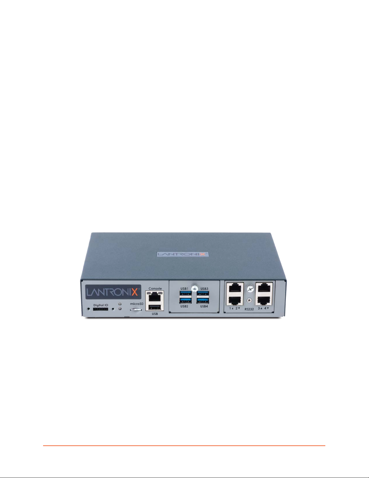
Figure 2-1 EMG 8500 Edge Management Gateway _____________________________________22
Figure 2-2 EMG 8500 Product Label _________________________________________________25
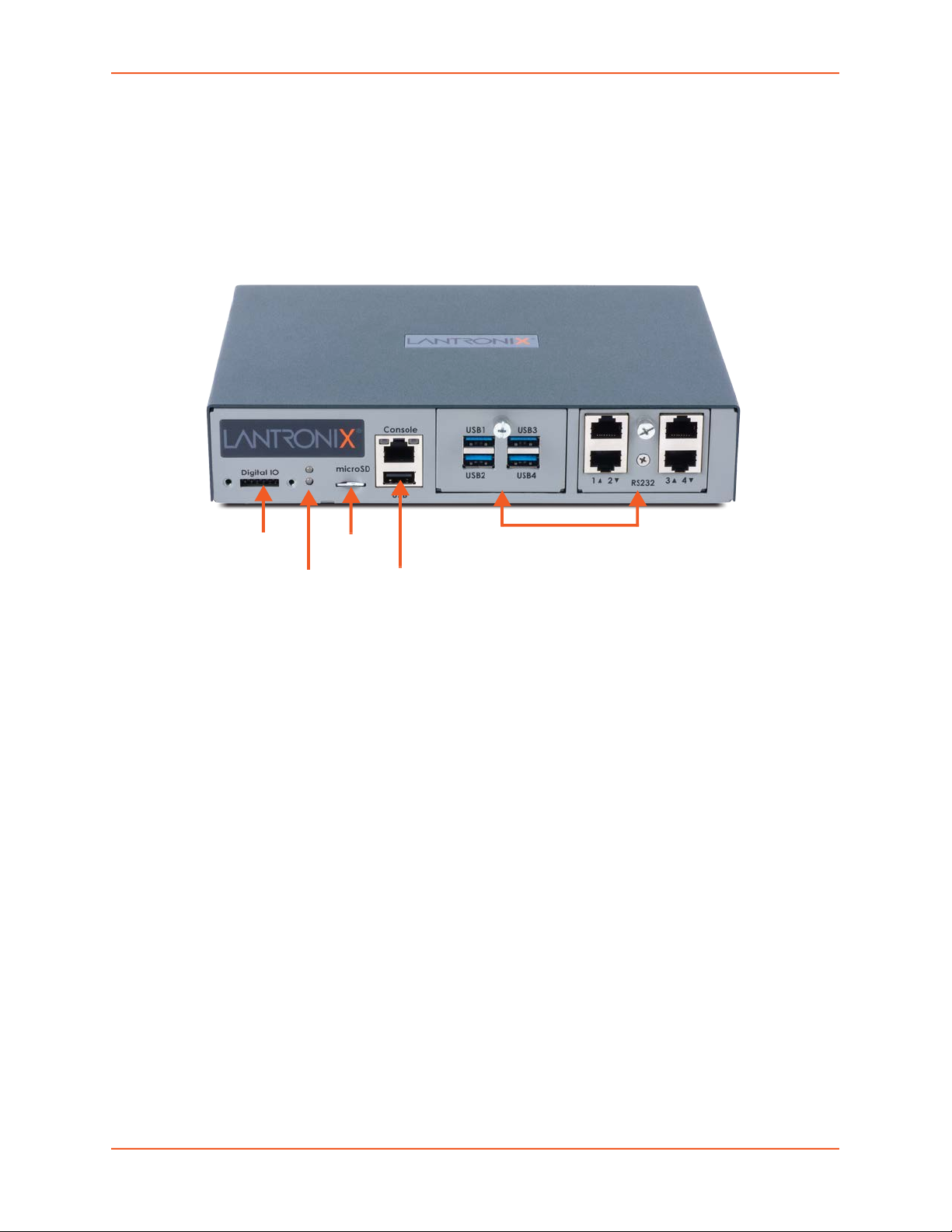
Figure 2-3 EMG 8500 Unit (front side) ________________________________________________26
Figure 2-4 EMG 8500 Unit (back side) ________________________________________________27
Figure 2-5 Console Port (Front Side) _________________________________________________29
Figure 2-7 I/O Modules ____________________________________________________________30
Figure 2-9 Dual Ethernet Network Connection __________________________________________31
Figure 2-10 Dual SFP Connection. Inserting the SFP transceiver ___________________________32
Figure 2-11 LTE Cellular Modem Module ______________________________________________33
Figure 2-13 Digital I/O Port ________________________________________________________34
Figure 3-4 Rack Mount Dimensions __________________________________________________ 40
Figure 3-5 Wall Mount Dimensions___________________________________________________41
Figure 3-8 Sample Device Port Connections (Front Side) _________________________________43
Figure 3-10 Sample Connectivity Module Configuration (Back Side) _________________________45
Figure 3-11 Power Input ___________________________________________________________46
Figure 4-2 Quick Setup ____________________________________________________________52
Figure 4-3 Quick Setup Completed in Web Manager _____________________________________54
Figure 4-4 Home _________________________________________________________________55
Figure 4-5 Beginning of Quick Setup Script ____________________________________________55
Figure 4-6 Quick Setup Completed in CLI _____________________________________________57
Figure 5-1 Web Page Layout _______________________________________________________59
Figure 5-2 Sample Dashboard ______________________________________________________60
Figure 6-1 Network > Network Settings (1 of 2) _________________________________________68
Figure 6-2 Network > Network Settings (2 of 2) _________________________________________69
Figure 6-3 Network Settings > SFP NIC Information & Diagnostics __________________________70
Figure 6-4 Network > Cellular Modem Settings Page_____________________________________77
Figure 6-5 Network > IP Filter ______________________________________________________79
Figure 6-6 Network > IP Filter Ruleset (Adding/Editing Rulesets) ___________________________81
Figure 6-7 Network > Routing _______________________________________________________83
Figure 6-8 Network > VPN (1 of 2) ___________________________________________________86
Figure 6-9 Network > VPN (2 of 2) ___________________________________________________87
Figure 6-10 Network > Security ____________________________________________________102
Figure 6-11 Network > Perf Monitoring _______________________________________________104
Figure 6-12 Performance Monitoring - Add/Edit Probe___________________________________106
Figure 6-14 Performance Monitoring - Operations ______________________________________112
EMG™ Edge Management Gateway User Guide 15
Page 16

Figure 6-15 FQDN List ___________________________________________________________113
Figure 7-1 Services > SSH/Telnet/Logging____________________________________________115
Figure 7-2 Services > SNMP ______________________________________________________119
Figure 7-3 Services > NFS & SMB/CIFS _____________________________________________123
Figure 7-4 Services > Secure Lantronix Network _______________________________________125
Figure 7-5 IP Address Login Page __________________________________________________126
Figure 7-6 SSH or Telnet CLI Session _______________________________________________ 126
Figure 7-7 Disabled Port Number Popup Window ______________________________________ 127
Figure 7-8 Services > Secure Lantronix Network - Search Options _________________________128
Figure 7-9 Services > Date & Time _________________________________________________131
Figure 7-10 Services > Web Server ________________________________________________133
Figure 7-11 Web Server - SSL Certificate_____________________________________________136
Figure 7-12 Web Server - Web Sessions _____________________________________________138
Figure 7-13 Services > ConsoleFlow ________________________________________________140
Figure 8-1 Devices > USB / SD Card ________________________________________________144
Figure 8-2 Devices > USB > Configure ______________________________________________145
Figure 8-3 Devices > SD Card > Configure ___________________________________________145
Figure 8-4 Firmware and Configurations - Manage Files _________________________________147
Figure 9-2 Devices > Device Status _________________________________________________150
Figure 9-3 Devices > Device Ports __________________________________________________151
Figure 9-4 Device Ports > Settings (1 of 2)____________________________________________154
Figure 9-5 Device Ports > Settings (2 of 2)____________________________________________155
Figure 9-7 Device Ports - Power Management_________________________________________165
Figure 9-8 Devices > Device Ports - Sensorsoft ________________________________________167
Figure 9-9 Sensorsoft Status ______________________________________________________168
Figure 9-10 Devices > Device Ports - Logging & Events _________________________________171
Figure 9-11 Devices > Console Port _________________________________________________ 174
Figure 9-12 Devices > Host Lists ___________________________________________________180
Figure 9-13 Devices >View Host Lists _______________________________________________182
Figure 9-14 Devices > Sites _______________________________________________________184
Figure 10-1 Devices > RPMs ______________________________________________________192
Figure 10-2 RPM Shutdown Order __________________________________________________193
Figure 10-3 RPM Notifications _____________________________________________________ 194
Figure 10-4 RPM Raw Data Log____________________________________________________194
Figure 10-5 RPM Logs ___________________________________________________________195
Figure 10-6 RPM Environmental Log ________________________________________________ 195
Figure 10-7 Devices > RPMs - Add Device ___________________________________________196
Figure 10-8 RPMs - Manage Device_________________________________________________ 199
EMG™ Edge Management Gateway User Guide 16
Page 17

Figure 10-9 RPMs - Outlets _______________________________________________________202
Figure 11-1 Devices > Scripts______________________________________________________206
Figure 11-2 Adding or Editing New Scripts ____________________________________________207
Figure 11-3 Scripts > Custom Scripts - Scheduler ______________________________________209
Figure 12-1 Terminal Server _______________________________________________________235
Figure 12-2 Remote Access Server _________________________________________________236
Figure 12-3 Reverse Terminal Server________________________________________________ 236
Figure 12-4 Multiport Device Server _________________________________________________237
Figure 12-5 Console Server _______________________________________________________238
Figure 12-6 Devices > Connections _________________________________________________239
Figure 12-7 Current Connections ___________________________________________________240
Figure 13-1 User Authentication > Auth Methods _______________________________________242
Figure 13-3 User Authentication > Local/Remote Users__________________________________245
Figure 13-4 User Authentication > Local/Remote User Settings ___________________________247
Figure 13-5 User Authentication > NIS _______________________________________________251
Figure 13-6 User Authentication > LDAP _____________________________________________255
Figure 13-7 User Authentication > RADIUS ___________________________________________259
Figure 13-8 User Authentication > Kerberos___________________________________________264
Figure 13-9 User Authentication > TACACS+__________________________________________268
Figure 13-10 User Authentication > Groups ___________________________________________272
Figure 13-11 User Authentication > SSH Keys_________________________________________275
Figure 13-12 Current Host Keys ____________________________________________________278
Figure 13-13 User Authentication > Custom Menus _____________________________________ 280
Figure 14-1 Maintenance > Firmware & Configurations __________________________________285
Figure 14-2 Network > Firmware/Config > Manage _____________________________________290
Figure 14-3 Maintenance > System Logs _____________________________________________291
Figure 14-4 View System Logs _____________________________________________________292
Figure 14-5 Maintenance > Audit Log________________________________________________293
Figure 14-6 Maintenance > Email Log _______________________________________________294
Figure 14-7 Maintenance > Diagnostics ______________________________________________295
Figure 14-8 Diagnostics Output ____________________________________________________297
Figure 14-9 Maintenance > Status/Reports ___________________________________________298
Figure 14-10 Generated Status/Reports______________________________________________300
Figure 14-11 Emailed Log or Report_________________________________________________ 301
Figure 14-12 About EMG _________________________________________________________302
Figure 14-13 Maintenance > Events _________________________________________________ 303
Figure 14-14 Maintenance > Banners________________________________________________305
Figure 15-1 EMG - Configuration ___________________________________________________307
EMG™ Edge Management Gateway User Guide 17
Page 18

Figure 15-2 Remote User Connected to a SUN Server via the Console Manager______________308
Figure 15-3 Dial-in (Text Mode) to a Remote Device ____________________________________309
Figure 15-4 Local Serial Connection to Network Device via Telnet _________________________311
Figure C-1 RJ45 Receptacle to DB25M DCE Adapter for the EMG Unit (PN 200.2066A)________409
Figure C-2 RJ45 Receptacle to DB25F DCE Adapter for the EMG Unit (PN 200.2067A) ________ 410
Figure C-3 RJ45 Receptacle to DB9M DCE Adapter for the EMG Unit (PN 200.2069A)_________410
Figure C-4 RJ45 Receptacle to DB9F DCE Adapter for the EMG Unit (PN 200.2070A) _________ 411
Figure C-5 RJ45 Receptacle to DB25M DTE Adapter (PN 200.2073) _______________________411
EMG™ Edge Management Gateway User Guide 18
Page 19

List of Tables
Table 2-6 Console (DTE) Port Pinout ________________________________________________29
Table 2-8 Device (DCE Reversed & DTE) Port Pinout ___________________________________30
Table 2-12 Front Panel LED Indicators _______________________________________________ 33
Table 3-1 EMG 8500 Parts ________________________________________________________35
Table 3-2 EMG 8500 Device Modules ________________________________________________35
Table 3-3 EMG Technical Specifications ______________________________________________37
Table 3-6 Console Port and Device Port - Reverse Pinout Disabled _________________________ 42
Table 3-7 Device Port - Reverse Pinout Enabled (Default) ________________________________42
Table 3-9 Available I/O Module Configurations _________________________________________44
Table 4-1 Methods of Assigning an IP Address _________________________________________50
Table 5-3 SCS Commands ________________________________________________________ 64
Table 5-4 CLI Keyboard Shortcuts ___________________________________________________ 65
Table 6-13 Error Conditions Detected by Probes ______________________________________111
Table 9-1 Supported I/O Module Configurations _______________________________________149
Table 9-6 Port Status and Counters _________________________________________________163
Table 11-4 Interface Script Syntax Definitions _________________________________________212
Table 11-5 Primary Commands ____________________________________________________213
Table 11-6 Secondary Commands _________________________________________________215
Table 11-7 Control Flow Commands ________________________________________________216
Table 13-2 User Types and Rights _________________________________________________244
Table 16-1 Actions and Category Options ___________________________________________ 313
EMG™ Edge Management Gateway User Guide 19
Page 20

1: About this Guide
Purpose and Audience
This guide provides the information needed to install, configure, and use the Lantronix EMG™
edge management gateway. The EMG gateway is for IT professionals who must remotely and
securely configure and administer servers, routers, switches, telephone equipment, or other
devices equipped with a serial port for facilities that are typically remote branch offices or
“distributed” IT locations.
Note: EMG edge management gateways are referred to as either EMG or as EMG 8500
when referring to the specific series. Edge management gateway or console manager
may be used to describe the EMG devices.
Summary of Chapters
The remaining chapters in this guide include:
Chapter Description
Chapter 2: Introduction Describes the EMG models, their main features, and the protocols they
support.
Chapter 3: Installation Provides technical specifications; describes connection form factors and
power supplies; provides instructions for installing the EMG in a rack.
Chapter 4: Quick Setup Provides instructions for getting your EMG unit up and running and for
configuring required settings.
Chapter 5: Web and
Command Line Interfaces
Chapter 6: Networking Provides instructions for configuring network ports, firewall and routing
Chapter 7: Services Provides instructions for enabling and disabling system logging, SSH and
Chapter 8: USB/SD Card Port Provides instructions for using the USB and SD Card ports.
Chapter 9: Device Ports Provides instructions for configuring global device port settings, individual
Chapter 10: Remote Power
Managers
Chapter 11: Scripts Provides instructions for creating scripts to automate tasks performed on the
Chapter 12: Connections Provides instructions for configuring connections and viewing, updating, or
Chapter 13: User
Authentication
Describes the web and command line interfaces available for configuring
the EMG.
The configuration chapters (6-15) provide detailed instructions for using the
web interface and include equivalent command line interface commands.
settings, and VPN.
Telnet logins, SNMP, SMTP, and the date and time.
device port settings, and console port settings.
Provides instructions for using RPMs.
EMG command line interface (CLI) or on device ports.
disconnecting a connection.
Provides instructions for enabling or disabling methods that authenticate
users who attempt to log in via the web, SSH, Telnet, or the console port.
Provides instructions for creating custom menus.
EMG™ Edge Management Gateway User Guide 20
Page 21

1: About this Guide
Chapter (continued) Description
Chapter 14: Maintenance Provides instructions for upgrading firmware, viewing system logs and
diagnostics, generating reports, and defining events. Includes information
about web pages and commands used to shut down and reboot the EMG.
Chapter 15: Application
Examples
Chapter 16: Command
Reference
Appendix A: Security
Considerations
Appendix B: Safety
Information
Appendix C: Adapters and
Pinouts
Appendix D: Protocol
Glossary
Appendix E: Compliance
Information
Shows three different configurations to set up and use the EMG unit.
Lists and describes all of the commands available on the EMG command
line interface.
Provides tips for enhancing EMG security.
Lists safety precautions for using the EMG.
Includes adapter and pinout diagrams.
Lists the protocols supported by the EMG unit with brief descriptions.
Provides information about the EMG unit’s compliance with industry
standards.
Additional Documentation
Visit the Lantronix Web site at www.lantronix.com/support/documentation for the latest
documentation and the following additional documentation.
Document Description
EMG Quick Start Guide Provides accessories and part number information,
EMG Product Brief Provides product overview and specifications.
hardware installation instructions, directions to connect the
EMG unit, and network IP configuration information.
EMG™ Edge Management Gateway User Guide 21
Page 22
2: Introduction
The EMG edge management gateway enables IT system administrators to manage remote
servers and IT infrastructure equipment securely over the Internet.
IT equipment can be configured, administered, and managed in a variety of ways, but most
devices have one of two methods in common: via USB port and/or via an RS-232 serial port,
sometimes called a console, auxiliary, or management port. These ports are often accessed
directly by connecting a terminal or laptop to them, meaning that the administrator must be in the
same physical location as the equipment. The EMG gives the administrator a way to access them
remotely from anywhere there is a network or modem connection.
EMG 8500 Overview
The EMG 8500 is a modular edge management gateway that offers serial RJ45 and USB console
connectivity with user swappable I/O modules and connectivity modules. The EMG unit can
accommodate up to two user swappable I/O modules (4 port serial RJ45 and/or 4 port serial USB).
For connectivity, the EMG provides dual Ethernet or dual small form-factor pluggable (SFP)
network ports and up to two user replaceable modules for one LTE cellular modem, and in a future
release for one Wi-Fi modem or dialup modem.
Figure 2-1 EMG 8500 Edge Management Gateway
Key Features
Console Management
Enables system administrators to remotely manage devices with serial and/or USB console
ports with RS-232C (now EIA-232) or USB compatible serial consoles in a 1U-tall rack space.
Provides up to 8 serial RJ45 RS-232 or USB Type A console connections.
Dual 10/100/1000 Base-T Ethernet or dual 1 Gb SFP network ports for in-band network device
access
EMG™ Edge Management Gateway User Guide 22
Page 23

2: Introduction
Local terminal or internal cellular modem (LTE cellular) for out-of-band network device access
Modular design allows user to add or swap I/O modules (RJ45, USB) and connectivity
modules (LTE cellular)
Data logging, device port buffering, network performance monitoring, system event logs and
console event notification via email
Integrated automatic fail-over/failback mechanism for seamless connection to IT equipment
Sun Break Safe compatible
Remote power manager (RPM) control of UPS and PDU devices
Scripting to automate tasks performed on the CLI or on device ports
Performance Monitoring
Performance Monitoring probes to analyze network performance
Security
Enterprise-grade security and secure user access control with local or remote authentication
Power
An external Universal AC (90W, 100-240V, 50/60 Hz) power supply provides power to the unit
DC power port. The DC power port supports 9 to 30Vdc.
Convection cooled, silent operation, low power consumption
Integration with Lantronix ConsoleFlow™
Compatible with Lantronix ConsoleFlow™management software for an end-to-end Out-of-
Band (OOB) management solution.
Applications
The EMG edge management gateway is suitable for remote and secure management of the
following types of IT equipment:
Servers: Unix, Linux, Windows, and others.
Networking equipment: Routers, switches, storage networking.
Telecom: PBX, voice switches.
Other systems with serial interfaces: Heating/cooling systems, security/building access
systems, uninterruptible power supply (UPS), medical devices.
EMG™ Edge Management Gateway User Guide 23
Page 24

Protocol Support
The EMG supports the following protocols:
TCP/IP network protocol
SSH, TLS, SSL, Telnet and TCP for connections in and out of device ports
DHCP and BOOTP for dynamic IP address assignment
DNS for IP address name resolution
SNMP for remote monitoring and management
SCP, FTP, and SFTP for file transfers and firmware upgrades
TFTP for firmware upgrades
SMTP for mail transfer
HTTPS (SSL) for secure browser-based configuration
NTP for time synchronization
UDP, PPP with PAP/CHAP, NFS and CIFS for data storage
LDAP/AD, NIS, RADIUS with VSA support, CHAP, PAP, Kerberos, TACACS+, and SecurID
(via RADIUS) for remote authentication
2: Introduction
Callback Control Protocol (CBCP) for PPP server callback
StrongSwan IPsec for VPN access
For brief descriptions of these protocols, see Appendix D: Protocol Glossary on page 412.
Configuration Methods
After installation, the EMG requires configuration. For the unit to operate correctly on a network, it
must have a unique IP address on the network. This IP address references the specific unit.
For details on how to configure the unit with basic network settings, see Chapter 4: Quick Setup.
The EMG provides the following methods for logging into the unit to configure EMG settings
monitor performance:
Web Manager: View and configure all settings through a secure, encrypted web interface
using most web browsers (Firefox, Chrome, or Internet Explorer with the latest browser
updates). See Chapter 5: Web and Command Line Interfaces.
Command Line Interface (CLI): The command mode may be accessed through Telnet, SSH,
Web Telnet/SSH or connecting a terminal (or a PC running a terminal emulation program) to
the unit’s console port. See Chapter 5: Web and Command Line Interfaces.
EMG™ Edge Management Gateway User Guide 24
Page 25
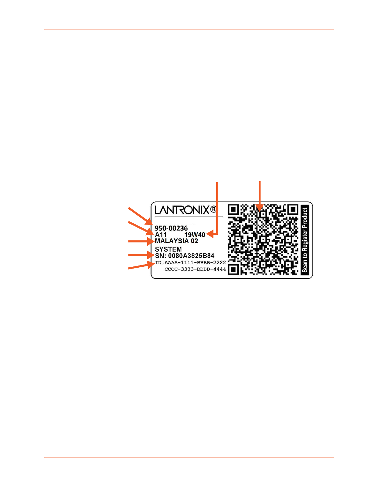
Product Information Label
The product information label on the unit contains the following information about the specific unit:
Bar Code
Product Part Number
Product Revision
Manufacturing Date Code
Country of Manufacturing Origin
Hardware Address (MAC address or serial number)
Device ID (used to connect to ConsoleFlow central management software)
2: Introduction
Figure 2-2 EMG 8500 Product Label
Product Part Number
Product Revision
Country of
Manufacturing Origin
Serial Number
Device ID
(ConsoleFlow)
Manufacturing
Date Code
Bar Code
EMG™ Edge Management Gateway User Guide 25
Page 26
Hardware Components
EMG Chassis: The EMG has a 1U-tall (1.75 inch), 212.6mm [8.37”] L x 167.68mm [6.60”] W
x 43.21mm [1.70”]
Front Chassis: Figure 2-3 shows the front view of the EMG:
H chassis. Options for rack mounting and wall mounting are available.
2: Introduction
Figure 2-3 EMG 8500 Unit (front side)
DIO Port Micro
SD Card
LEDs
The front of the EMG unit appearance and function will depend
upon the type(s) of I/O modules installed in Bay 1 and Bay 2.
Console Port
USB Port
Two I/O Modular Device Port Bays
- Two I/O Module Bays are available to accommodate a total of 8 device ports depending
on the number of I/O modules installed. Configuration possibilities are listed below. See
Table 3-9 on page 44 which describes different I/O module configurations.
Up to two 4 port RJ45 I/O modules can be installed to provide a maximum of 8 serial
RS-232C (EIA-232) device ports. The serial RJ45 ports match the RJ45 pinouts of the
console ports of many popular devices found in a network environment, and where
different can be converted using Lantronix adapters. The RJ45 ports have software
reversible pinouts to switch between digital terminal equipment (DTE) and digital
communications equipment (DCE) applications. See Appendix C: Adapters and
Pinouts on page 409 for more information on serial adapters and pin-outs.
Up to two 4 port USB I/O modules can be installed to provide a maximum of 8 USB
type A device ports.
A combination of 4 port USB I/O modules and 4 port RJ45 I/O modules can be
installed to provide up to 8 serial device ports.
- One serial console port (RJ45, RS-232) for VT100 terminal or PC with emulation with
light emitting diode (LED) for activity indicators
- One 2.0 USB type A port (HS, FS, LS) for use with flash drive or external USB modem
(V.92 dialup)
EMG™ Edge Management Gateway User Guide 26
Page 27
2: Introduction
One Micro Secure Digital (micro SD) memory card slot for use with micro SD card to collect
logs, save configurations, and update firmware. (Micro SD card provided by the user)
- One digital IO (DIO) port with two digital inputs and one relay output (terminal block) for
use with sensors
- LED indicators for ethernet port status and connectivity module status
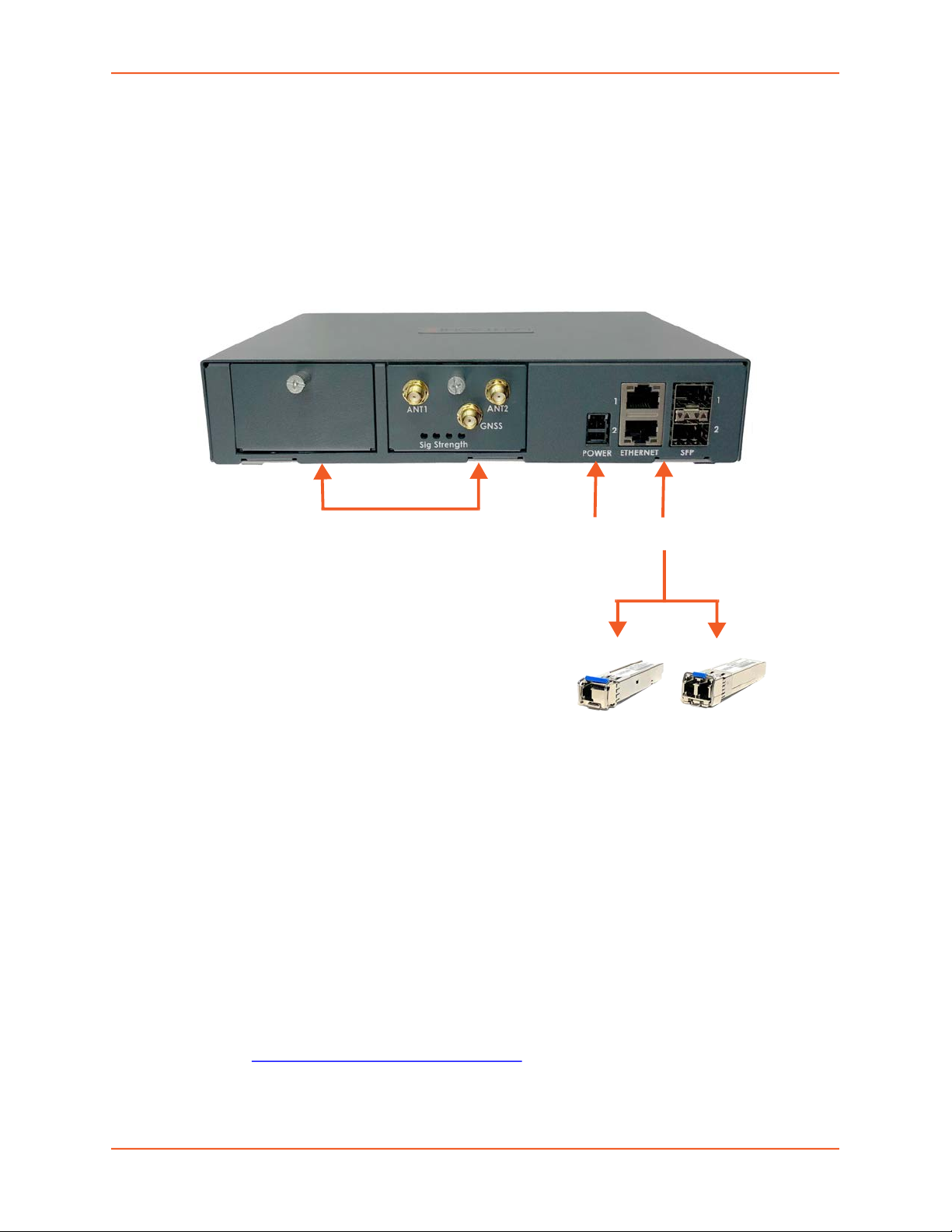
Back Chassis: Figure 2-4 shows the back view of the EMG 8500:
Figure 2-4 EMG 8500 Unit (back side)
Two Connectivity Module Bays
The appearance and function of the EMG will
depend upon the type(s) of the installed
connectivity modules.
The EMG supports the use of single mode and
multi-mode fiber optic SFP transceiver modules.
Power inlet
Dual Ethernet and
SFP Ports
- Two Connectivity Module Bays accommodate up to two connectivity modules.
Configuration possibilities are listed below. See Figure 3-10 on page 45 for a sample
connectivity module configuration.
One LTE cellular modem module can be installed to provide cellular connectivity.
- Network Interface: Dual 10/100/1000 Base-T Ethernet port I/F card. Ethernet ports are
referred to as Eth1 and Eth2 in the user interface and this user guide.
- Network Interface: Dual 1 Gigabit-capable SFP port I/F card to support single or multi-
mode fiber optic SFP transceiver modules. SFP transceiver modules are referred to as
SFP1 and SFP2 in the user interface and this user guide.
Note: EMG will recognize two network connections. Either Eth1 or SFP1 is active, but
not both. Similarly, either Eth2 or SFP2 is active, but not both.
Lantronix offers SFP Transceivers (“modules”) for EMG 8500 edge management
gateways and SLC 8000 console managers with fiber SFP ports. To learn more, go to
https://www.lantronix.com/products/sfp/
SFP transceiver modules are provided by users according to fiber mode and brand
preferences.
EMG™ Edge Management Gateway User Guide 27
Page 28

Network ports and the SFP port have LEDs to indicate link and activity status. If a
single mode and a multi-mode are both installed on the EMG unit, the device can be
configured to utilize one mode at a time.
- Power supply inlet: The unit accepts a 9 to 30 Vdc power input via a back-panel
connector. A universal AC power input (100-240V, 50/60 Hz) to 12 Vdc power supply brick
is available for use with the unit.
System Features
This section describes system features, interfaces, and ports of the EMG.
Access Control
The system administrator controls access to attached servers or devices by assigning access
rights to up to 128 user profiles. Each user has an assigned ID, password, and access rights.
Other user profile access options may include externally configured authentication methods such
as Radius, TACACS+, NIS, and LDAP. Groups are supported in LDAP, RADIUS (using VSA), and
TACACS+ (using priv_lvl).
2: Introduction
Device Port Buffer
The EMG unit supports real-time data logging for each device port. The port can save the data log
to a file, send an email notification of an issue, or take no action.
You can define the path for logged data on a port-by-port basis, configure file size and number of
files per port for each logging event, and configure the device log to send an email alert message
automatically to the appropriate parties indicating a particular error.
Console Port Interface
The EMG unit supports local access through a dedicated front panel serial console port (see
Figure 2-3). The console port supports the RS-232C (EIA-232) standard. RJ45 cabling (e.g.,
category 5 or 6 patch cabling) is used.
Figure 2-5 and Table 2-6 show the Console port and port pinout.
The console port supports the following baud rate options: 300, 600, 1200, 2400, 4800, 9600,
19200, 38400, 57600, 115200, 230400, 460800, and 921600 baud.
EMG™ Edge Management Gateway User Guide 28
Page 29
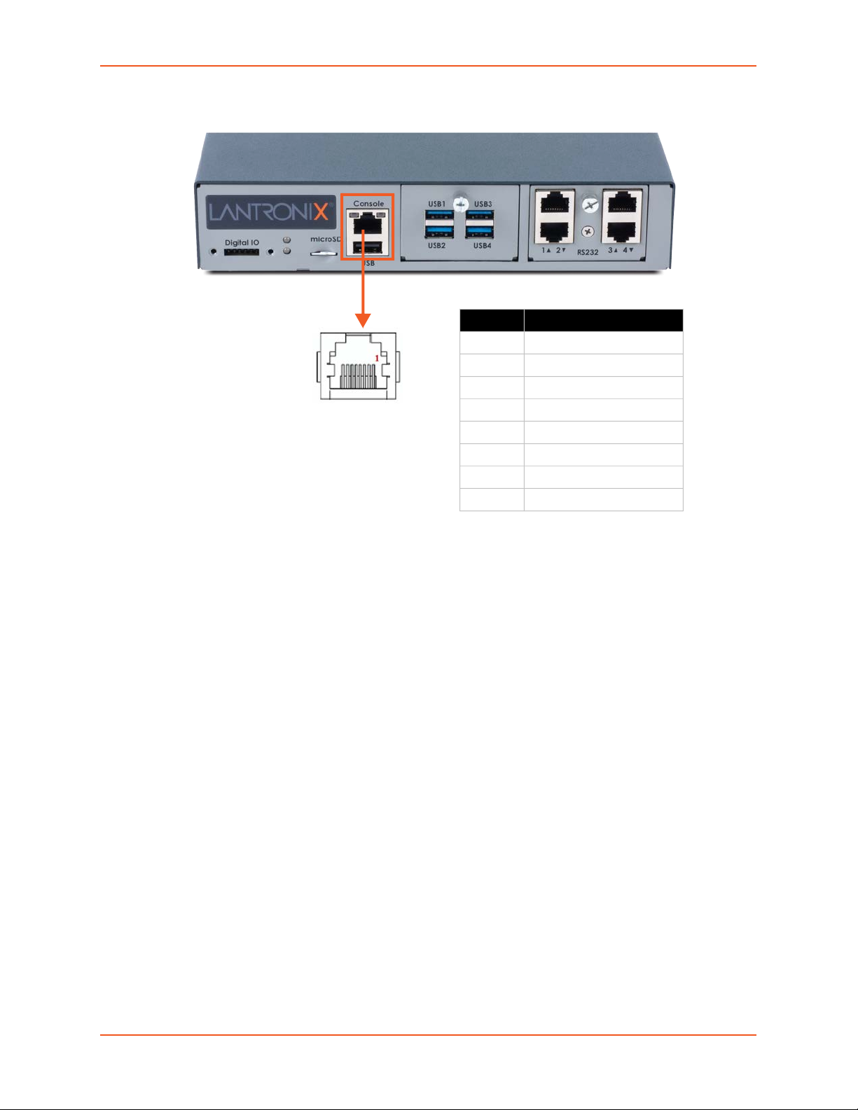
Figure 2-5 Console Port (Front Side)
Table 2-6 Console (DTE) Port Pinout
DTE Pin Description
1 RTS (output)
2 DTR (output)
3 TXD (output)
4 Ground
5 Ground
6 RXD (input)
7 DSR (input)
8 CTS (input)
2: Introduction
Device Port Interfaces
RS-232 RJ45 Interface
The device ports are located on the front of the EMG unit in the I/O module device port bays (see
Figure 2-3).
All devices attached to the RJ45 device ports must support the RS-232C (EIA-232) standard. For
serial RJ45 device ports, RJ45 cabling (e.g., category 5 or 6 patch cabling) is used.
Serial RJ45 device ports for the EMG are reversed by default so that straight-through RJ45 patch
cables may be used to connect to Cisco and Sun RJ45 serial console ports. See Figure 2-7 and
Table 2-8. The RJ45 ports have software reversible pinouts to switch between DTE and DCE
applications.
Note: RJ45 to DB9/DB25 adapters are available from Lantronix. For serial pinout
information, see the Appendix C: Adapters and Pinouts on page 409.
Additional device port features:
RAW TCP, Telnet or SSH to a serial port by IP address per port or by IP address and TCP port
number
Simultaneous access on the same port - “listen” and “direct” connect mode
Device ports support the following baud rate options: 300, 600, 1200, 2400, 4800, 9600,
19200, 38400, 57600, 115200, 230400, 460800, and 921600 baud.
USB Interface
EMG™ Edge Management Gateway User Guide 29
Page 30
2: Introduction
The USB device ports are located on the front of the EMG unit in the I/O module device port bays
(see Figure 2-3). USB device ports can be used with a USB type A connector to serial adapter, if
needed.
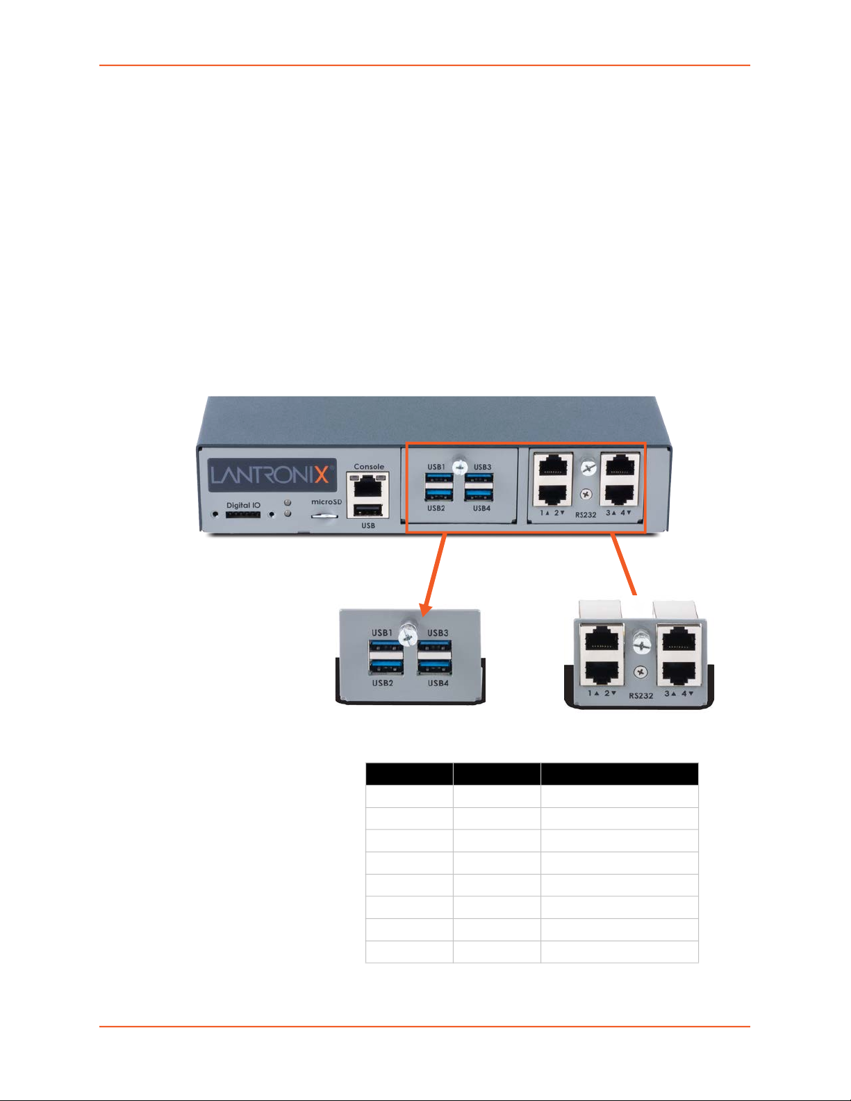
I/O Modules
EMG provides two I/O slots for user replaceable I/O modules to be installed on the front side of the
EMG 8500 unit.
Figure 2-7 shows a sample configuration of an EMG 8500 unit containing one 4 port USB I/O
module in Bay 1 and one 4 port RJ45 I/O module in Bay 2 for a total of 8 device ports.
Note: When installing the I/O modules, they can be populated or swapped in any order.
One but not both of the slots can be empty. The I/O modules must only be installed on the
front of the unit, never in the connectivity slots on the back.
Figure 2-7 I/O Modules
I/O Module Device Port Bays
Bay 1 Bay 2
4-port RJ45 I/O module4-port USB I/O module
Table 2-8 Device (DCE Reversed & DTE) Port Pinout
DCE Pin DTE Pin Description
8 1 RTS (output)
7 2 DTR (output)
6 3 TXD (output)
5 4 Ground
4 5 Ground
3 6 RXD (input)
2 7 DSR (input)
1 8 CTS (input)
EMG™ Edge Management Gateway User Guide 30
Page 31

2: Introduction
Network Connections
Dual Ethernet Port and Dual SFP Port
The back side of the EMG unit is equipped with two Ethernet and two SFP ports. The EMG
network interfaces are 10/100/1000 Base-T Ethernet for use with a conventional Ethernet network as
shown in Figure 2-9. Use standard RJ45-terminated cables, such as a Category 5 or 6 patch cable.
CAT5E or better cables are recommended for 1000 Base Ethernet. Network parameters must be
configured before the EMG can be accessed over the network.
The SFP interfaces support the use of single and multi-mode SFP transceivers. Fiber optic 1 Gigabit
SFP transceiver modules may be used. See Figure 2-10.
Note: EMG will recognize two network connections. Either Eth1 or SFP1 is active, but
not both. Either Eth2 or SFP2 is active, but not both.
One possible use for the two Ethernet ports is to have one port on a private, secure network and
the other on a public, unsecured network. The EMG can also be equipped with a factory-installed
network interface card (NIC) (Ethernet RJ45 or SFP ports). The NIC with SFP ports can support
single/multi-mode fiber optic SFP transceiver modules at 1 Gigabit speed.
Ethernet and SFP LEDs
The Ethernet ports and the SFP ports contain LEDs. The LED indicators are the following:
Green LED - indicates link status
Yellow LED - indicates activity status
Figure 2-9 Dual Ethernet Network Connection
Bay 1 Bay 2
EMG™ Edge Management Gateway User Guide 31
Page 32

Figure 2-10 Dual SFP Connection. Inserting the SFP transceiver
2: Introduction
Connectivity Modules
EMG provides two connectivity slots for user replaceable connectivity modules on the back of the
unit.
Note: When installing the connectivity modules, they can be populated or swapped in
any order. One or both of the slots can be empty. The connectivity modules must only be
installed on the back of the unit, never in the I/O slots on the front.
LTE Cellular Modem
One LTE/4G cellular modem may be installed in either connectivity slot. The LTE cellular modem
may be configured to function as the failover interface with Eth1 as the primary link.
The LTE cellular modem module supports one main antenna, one AUX antenna, and one GPS
antenna for geolocation. (The geolocation function is not active in the current release).
The LTE cellular modem module supports one external SIM card, provided by the user. The SIM
card slot is located on the inside of the cellular modem module, as shown in Figure 2-11. To install
the SIM card, power off the EMG unit, unscrew the module faceplate and remove it from the EMG
unit. Insert the SIM card into the slot and replace the cellular modem module in the EMG unit.
EMG™ Edge Management Gateway User Guide 32
Page 33

Figure 2-11 LTE Cellular Modem Module
SIM card
LTE cellular module
2: Introduction
Front Panel LEDs
The front panel LEDs provide quick visual troubleshooting. Table 2-12 describes the front panel
LED indicators.
Table 2-12 Front Panel LED Indicators
Indicator LED 1 (Ethernet port) LED 2 (Connectivity)
Solid Green At least one of the Ethernet ports has a
link, or both Ethernet ports are
disabled.
Solid Orange Not applicable An LTE modem module is installed but
Blinking Red None of the Ethernet ports has a link. An LTE modem module is installed but
Indicates one of the following
conditions:
There are no connectivity modules
installed
An LTE modem module is installed
and is disabled
An LTE modem module is installed
and has a link
no SIM card is present
does not have a link.
Digital IO Port
The terminal block digital input relay output is located on the front panel of the EMG unit. It
provides two digital inputs and one relay output (terminal block) for use with sensors. The DIO port
requires an adapter, which is available and sold separately. Figure 2-13 shows the DIO adapter
installed on the EMG 8500 with the DIO port pin order and pin definition.
EMG™ Edge Management Gateway User Guide 33
Page 34

Figure 2-13 Digital I/O Port
The DIO connector description is provided below.
Connector Description
Relay Output Output supports 1A 24V
Inputs Inputs accept voltage 0 to 30 VDC.
ON: Max 30 VDC
Min 2 VDC
OFF: Max 0.7 VDC
Min 0 VDC
2: Introduction
Pin Number Pin Definition
1 Relay Out
2 Relay In
3 Input1+
4 Input1-
5 Input2+
6 Input2-
EMG™ Edge Management Gateway User Guide 34
Page 35

3: Installation
This chapter provides a high-level procedure for installing the EMG followed by more detailed
information about the EMG connections and power supplies.
Caution: To avoid physical and electrical hazards, please read
Appendix A: Security Considerations before installing the EMG.
Package Contents
The EMG 8500 package includes the following items. Verify and inspect the contents of the EMG
package using the enclosed packing slip. If any item is missing or damaged, contact your place of
purchase immediately.
Name
One EMG8500 EDGE MANAGEMENT GATEWAY
RJ45 to DB9F Adapter
RJ45 to RJ45 Cat5 Cable, 6.6 ft (2m) straight-through RJ45 patch
RJ45 Loopback Adapter
External Universal AC (90W, 100-240V, 50/60 Hz) power supply
North American Power cord - 110V AC power cord, 8 ft (2.43m), RoHS
Power cords for international regions are available and sold separately.
Note:
EMG Quick Start Guide
Table 3-1 EMG 8500 Parts
The following user replaceable device modules are available and sold separately.
Table 3-2 EMG 8500 Device Modules
Name
User Replaceable Device Modules
I/O Modules
EMG 8500 FRU, RS232 SERIAL 4-PORT (UART)
EMG 8500 FRU, USB 4-PORT
Connectivity Modules
EMG 8500 FRU, LTE, US
EMG 8500 FRU, LTE, APAC
Additional parts and accessories are available and sold separately. For details and purchasing
information, refer to the next section Order Information.
External DIO adapter
Wall mount kit
Rail mount kit
EMG™ Edge Management Gateway User Guide 35
Page 36

3: Installation
Order Information
To view order information, part numbers and extended support options, go to https://
www.lantronix.com/products/lantronix-emg/#tab-order-now.
User Supplied Items
To complete your installation you will need the following items:
Medium size Phillips screwdriver to install the mounting brackets to the EMG unit, if applicable
One or more serial devices that require network connectivity
A serial cable for each serial device.
- For RJ45 ports, you may use a straight-through RJ45 patch cable to connect to Cisco and
Sun RJ45 serial console ports.
- For USB ports, use a cable with a USB Type A connector
- For information about Lantronix adapters, see Appendix C: Adapters and Pinouts.
An available connection to your Ethernet network and an Ethernet cable CAT5E or better
cables are recommended for 1000 Base Ethernet.
A working AC power outlet to power the unit using the included AC (90W, 100-240V, 50/60
Hz) power supply.
If the LTE cellular modem is installed, a network SIM card (and data services) from a service
provider
Customize an EMG
Build any combination up to 8 managed console ports and up to two connectivity modules by
following these steps:
1. Pick a baseline configuration:
I/O: 4 port RS-232 or 4 port USB or two 4 port RS-232 modules
Connectivity module: Zero or one LTE module
2. Add up to one I/O module and up to two connectivity modules:
I/O: 4 port RS-232 or 4 port USB
EMG™ Edge Management Gateway User Guide 36
Page 37

Connectivity module: LTE or Wi-Fi module (coming soon)
3. Protect the investment with various extended warranty and service options. Go to https://
www.lantronix.com/products/lantronix-emg/#tab-order-now to purchase extended support.
Hardware Specifications
Table 3-3 EMG Technical Specifications
Component Description
Serial Interface (Device)
USB 2.0 Interface
(Device)
Serial Interface (Console)
Network Interface
Up to 8 RJ45-type 8-conductor connectors as up to two 4 port RJ45 I/O
Speed software selectable (300 to 921600 baud)
Up to 8 USB type A (Host) as up to two 4 port USB I/O modules can be
HS, FS, and LS
Capable of providing VBUS 5V up to 100 mA per port, but not to exceed 400
May be used with a USB-to-serial adapter to connect a serial device, if
Caution: USB ports are designed for data traffic only. They are not
designed for charging or powering devices. Over-current conditions on
VBUS 5V may disrupt operations.
(1) RJ45-type 8-pin connector (DTE)
Speed software selectable (300 to 921600 baud)
LEDs:
(2) 10/100/1000 Base-T RJ45 Ethernet with LED indicators:
AND
(2) SFP ports to support standard fiber SFP transceiver modules (single or
active, but not both Eth and SFP.
3: Installation
modules can be installed. These connectors have individually configurable
standard and reversible pinouts, 4 ports per I/O module.
Note: Serial RJ45 device ports for the EMG are reversed by default.
installed.
mA total per 4 port USB I/O module.
needed. Please contact Lantronix for the list of tested adapters.
Green light ON indicates data transmission activity
Yellow light ON indicates data receiving activity
Green light ON indicates a link at 1000 Base-T.
Green light OFF indicates a link at other speeds or no link.
Yellow light ON indicates a link is established.
Yellow light blinking indicates activity.
multi-mode) at speed 1 Gigabit. with LED indicators:
Green light ON indicates a link is established.
Green light OFF indicates no link.
Yellow light steady ON indicates no activity.
Yellow light blinking indicates activity.
Note: Either Eth1 and Eth2 ports are active or SFP1 and SFP2 ports are
EMG™ Edge Management Gateway User Guide 37
Page 38

3: Installation
Component (continued) Description
Connectivity Modules (2) connectivity slots to support 2 connectivity modules.
One LTE/4G cellular modem
One Wi-Fi module (coming soon)
Power
Dimensions
(L x W x H)
Weight 1.406 kg (3.10 lbs)
Temperature
Relative Humidity
Front USB Port
Front Memory Card (1) Secure Digital (micro SD) memory card slot supporting:
Internal Memory Optional: 128 GB Flash internal storage
Front DIO Port (1) Digital IO slot with two digital inputs and one relay output (terminal block)
LED Indicators
Operating Atmosphere
Caution: EQUIPMENT
IS FOR INDOOR USE
ONLY!
Input: DC jack, 9-30 VDC (standard)
External AC (90W, 100-240V, 50/60 Hz) power supply shipped with unit
212.6mm [8.37”] x 167.68mm [6.60”] x 43.21mm [1.70”], 1U
Operating: 0 to 50°C (32 to 122°F)
Storage: -20 to 80°C (-4 to 176°F)
Heat flow rate: TBD BTU per hour
Operating: 10% to 90% non-condensing
Storage: 10% to 90% non-condensing
(1) port, type A, host USB 2.0 (HS, FS, LS)
SD
SDHC
Ethernet port (upper LED on front panel)
Connectivity (lower LED on front panel)
RJ45 Ethernet (Activity/Link)
SFP (Activity/Link)
LTE Signal Strength
For use at altitudes no more than 2000 meters above sea level only.
For use in non-tropical conditions only.
Physical Installation
Install the EMG as a free-standing desktop unit, mounted on a wall, or mounted in an EIA-standard
19-inch rack (1U tall).
The EMG module uses convection cooling to dissipate excess heat.
To install the EMG unit:
1. If you have purchased additional I/O or Connectivity modules, install these modules.
For I/O modules, see I/O Module Installation (on page 47).
For Connectivity modules, see Connectivity Module Installation (on page 48).
Note: Always remove the power cord from the unit prior to installing or removing the I/O
or Connectivity modules.
EMG™ Edge Management Gateway User Guide 38
Page 39

3: Installation
2. Prepare the EMG unit for installation:
If free-standing, attach the adhesive-backed rubber feet to the base of the EMG unit.
If rack-mounted or wall-mounted, attach the brackets on the sides of the EMG unit using a
screw driver and the screws provided with the mounting kit.
3. Mount the EMG unit.
If free-standing, place the unit securely on a desktop or other flat horizontal surface.
If rack-mounted, mount the unit securely in a 19-inch rack. See Rack Mount Installation
(on page 39).
If wall-mounted, mount the unit securely on a flat vertical surface. See Wall Mounting
Instructions (on page 40).
Warning: Do not block the air vents on the sides of the EMG module. If you mount
the EMG in an enclosed rack, we recommend that the rack have a
ventilation fan to provide adequate airflow through the EMG unit.
4. Connect the serial device(s) to the EMG unit’s device ports. See Connecting to a Device Port
(on page 41).
5. Choose one of the following options:
To configure the EMG using the network, or to monitor serial devices on the network,
connect at least one EMG network port to a network. See Connecting to Network Ports
(on page 44).
To configure the EMG unit using a dumb terminal or a computer with terminal emulation,
connect the terminal or PC to the front panel EMG console port. See
Connecting Terminals (on page 45).
6. Connect the power cord to power on the unit. See Power Input (on page 46).
7. Wait approximately one minute for the boot process to complete.
The first time the EMG boots, it attempts to get an IP address from DHCP. To configure the
network settings, see Chapter 4: Quick Setup.
Rack Mount Installation
Attach the brackets on the sides of the EMG unit using a screwdriver and the screws provided with
the mounting kit.
Mount the unit securely in a 19-inch rack.
EMG™ Edge Management Gateway User Guide 39
Page 40

3: Installation
Figure 3-4 Rack Mount Dimensions
Warning: Do not block the air vents on the sides of the EMG module. If you mount
the EMG in an enclosed rack, we recommend that the rack have a
ventilation fan to provide adequate airflow through the EMG unit.
Wall Mounting Instructions
For installations to Walls Requiring Anchors
These instructions are for mounting the EMG to walls made of solid concrete, block, brick, or
plasterboard.
(1) Wall mount:
1. Locate the place where you want to mount the unit and mark four holes using your EMG
mount as a guide for the screws. See Figure 3-5 for the location of the screw holes.
2. Drill four 3/16 inch (4.8 mm) diameter holes at a depth of 1.25 inches (32 mm).
3. Insert the anchors until they are flush with the surface.
4. Thread four pan head top mount screws through the unit mount hole and through the anchor,
and tighten them.
(2) Keyhole mount:
1. Locate the place where you want to mount the unit and mark two holes using your EMG mount
as a guide for the screws. See Figure 3-5 for the location of the screw holes.
2. Drill two 3/16 inch (4.8 mm) diameter holes at a depth of 1.25 inches (32 mm).
3. Insert the anchors until they are flush with the surface.
4. Thread two pan head top mount screws through the unit mount hole and through the anchor,
and reserve 0.08” to 0.12” (2-3 mm) clearance to the anchor surface.
5. Hang the EMG unit where both keyholes of wall mounts can go through the screw heads on
the wall.
For installations to Walls Not Requiring Anchors
These instructions are for mounting the EMG to walls made of solid wood at least two (2) inches
thick.
(1) Wall mount:
EMG™ Edge Management Gateway User Guide 40
Page 41

3: Installation
1. Locate the place where you want to mount the unit and mark four holes using your EMG
mount as a guide for the screws. See Figure 3-5 for the location of the screw holes.
2. Drill four 3/16 inch (4.8 mm) diameter holes at a depth of 1.25 inches (32 mm).
3. Thread four pan head top mount screws through the unit mount hole and tighten them.
(2) Keyhole mount:
1. Locate the place where you want to mount the unit and mark two holes using your EMG mount
as a guide for the screws. See Figure 3-5 for the location of the screw holes.
2. Drill two 3/16 inch (4.8 mm) diameter holes at a depth of 1.25 inches (32 mm).
3. Thread two pan head top mount screws through the unit mount hole and reserve 0.08” to 0.12”
(2-3 mm) clearance to the wall surface.
4. Hang the EMG unit where both keyholes of wall mounts can go through the screw heads on
the wall.
Figure 3-5 Wall Mount Dimensions
(1) Wall
mount
(2) Keyhole
mount
(1)
(1)
(2)
(1)
Connecting to a Device Port
You can connect almost any device that has a serial console port to a device port on the EMG unit
for remote administration. The console port must support the RS-232C interface.
Note: Many servers must either have the serial port enabled as a console or the
keyboard and mouse detached. Consult the server hardware and/or software
documentation for more information.
To connect to a serial RJ45 device port:
1. Connect one end of the Cat 5 cable to the device port.
2. Connect the other end of the Cat 5 cable to an RJ45 serial console port on the serial device or
use a Lantronix serial console adapter to connect it to other port types.
EMG™ Edge Management Gateway User Guide 41
Page 42

Notes:
3: Installation
See Device Port Commands to enable or disable reverse pinouts through the CLI.
Table 3-6 and Table 3-7 provide additional information on reverse pinouts.
See Appendix C: Adapters and Pinouts for information about Lantronix adapters.
Table 3-6 Console Port and Device Port - Reverse Pinout Disabled
Pin Number Description
1 RTS (output)
2 DTR (output)
3 TXD (output)
4 Ground
5 Ground
6 RXD (input)
7 DSR (input)
8 CTS (input)
Table 3-7 Device Port - Reverse Pinout Enabled (Default)
Pin Number Description
1 CTS (input)
2 DSR (input)
3 RXD (input)
4 Ground
5 Ground
6 TXD (output)
7 DTR (output)
8 RTS (output)
To connect to a USB device port:
1. Connect the USB type A connector of a USB cable to a device port.
2. Connect the other end of the USB cable to a USB console port.
Figure 3-8 shows a sample I/O module installation with one 4-port RJ45 I/O module and one 4-port
USB I/O module, and how the device ports correspond to the buttons on the Web Manager
Dashboard.
EMG™ Edge Management Gateway User Guide 42
Page 43

Figure 3-8 Sample Device Port Connections (Front Side)
Dashboard
Bay 1 Bay 2
4-Port USB
I/O Module
4-Port RJ45
I/O Module
3: Installation
Modular Expansion for I/O Module Bays
The EMG module configuration can be changed by adding or replacing I/O modules in the I/O
module bays. When populating the bays, Bay 1 and Bay 2 may be populated in any order and one
module may be left empty. The bays are ordered from left to right: Bay 1 is the slot next to the
console port and USB port and Bay 2 is the slot to the right of Bay 1. See Figure 3-8.
Any changes to the I/O modules must be done while the EMG unit is powered off. Table 3-9 shows
the available I/O module configurations. To install an I/O module, refer to I/O Module Installation
on page 47.
Warning: The I/O module slots on the front of the EMG unit may only be used with
the RJ45 or USB I/O modules. Do not insert the connectivity modules on
the front of the EMG unit.
EMG™ Edge Management Gateway User Guide 43
Page 44

Table 3-9 Available I/O Module Configurations
3: Installation
Connecting to Network Ports
The EMG network ports, 10/100/1000 Base-T Ethernet, allow remote access to the attached
devices and the system administrative functions. Use a standard RJ45-terminated Category 5
cable to connect to the network port. A CAT5e or better cable is recommended for use with a 1000
Base-T Ethernet connection.
Note: One possible use for the two Ethernet ports is to have one port on a private,
secure network, and the other on an unsecured network.
Modular Expansion for Connectivity Module Bays
The EMG module configuration can be changed by adding or replacing connectivity modules in
the Connectivity module bays. Bay 1 and Bay 2 may be populated in any order and one or both
bays may be left empty. The bays are ordered from left to right: Bay 1 is the slot on the left side of
the back panel and Bay 2 is the slot to the right of Bay 1. See Figure 3-10.
Any changes to the connectivity modules must be done while the EMG unit is powered off. Figure
3-10 shows a sample connectivity module installation with one LTE module, and how the
connectivity interfaces correspond to the buttons on the Dashboard. and how the device ports
correspond to the buttons on the Web Manager
To install a connectivity module, refer to Connectivity Module Installation on page 48.
Warning: The Connectivity module slots on the back of the EMG unit may only be
used with the connectivity modules. Do not insert the I/O modules in the
slots on the back of the EMG unit.
EMG™ Edge Management Gateway User Guide 44
Page 45

3: Installation
Figure 3-10 Sample Connectivity Module Configuration (Back Side)
Web Manager
Dashboard
Bay 1(empty) Bay 2 Ethernet/SFP
Connecting Terminals
The console port is for local access to the EMG and the attached devices. You may attach a dumb
terminal or a computer with terminal emulation to the console port. The EMG console port uses
RS-232C protocol and supports VT100 emulation. The default serial settings are:
9600 baud
8 bit data
No parity
1 stop bit
No flow control
To connect the console port to a terminal or computer with terminal emulation, Lantronix offers
optional adapters that provide a connection between an RJ45 jack and a DB9 or DB25 connector.
The console port is configured as DTE (non-reversed RJ45). See Appendix C: Adapters and
Pinouts for more information.
To connect a terminal:
1. Attach the Lantronix adapter to your terminal (typically a PN 200.2066A adapter - see
Figure C-1) or your PC's serial port (use PN 200. adapter - see Figure C-4).
2. Connect the Cat 5 cable to the adapter, and connect the other end to the EMG console port.
3. Turn on the terminal or start your computer's communication program (e.g., PuTTY or
TeraTerm Pro).
4. Once the EMG is running, press Enter to establish connection. You should see the model
name and a login prompt on your terminal. On a factory default EMG you may log in with the
default user name sysadmin and the password PASS.
Note: For security purposes, we recommend that you change the default password and
choose a strong password.
EMG™ Edge Management Gateway User Guide 45
Page 46

3: Installation
Power Input
The EMG has a DC input jack connector for applying 9 to 30V DC. The EMG ships with an
external 100 to 200VAC 50/60Hz to 12V DC power supply brick for supplying power to the DC
input jack. (See Package Contents on page 35.)
Warning: Risk of serious electric shock! Disconnect the power cord before
servicing the EMG.
Figure 3-11 Power Input
Pin assignments
Pin 1: Input voltage 9-30 VDC
Pin 2: Power supply fault/power fail (active
low)
Pin 3: Ground
Pin 4: Earth Ground
EMG™ Edge Management Gateway User Guide 46
Page 47

3: Installation
I/O Module Installation
The EMG module port configuration can be changed by adding or replacing I/O modules in the I/O
module bays.
Warning: Install the I/O module on the front only of the EMG unit. Do not insert
any other module on the front of the EMG unit. Doing so may damage
the EMG unit and will void the warranty.
To install an I/O module:
1. Disconnect the power cord from the EMG unit and from the wall outlet. The EMG must be
powered off when installing or replacing the modules.
2. On the front of the EMG unit, locate the module bay where the module will be inserted.
3. Unscrew the existing module or faceplate from the module bay with your fingers and carefully
remove it from the module bay.
4. Insert the module into the module bay making sure the module sits completely and securely in
the housing.
5. The module will sit flush with the EMG chassis.
6. Tighten the screw on the module with your fingers. Be careful not to over tighten it.
7. To verify the new module is recognized, connect power to the EMG, wait for it to boot, and log
EMG™ Edge Management Gateway User Guide 47
Page 48

3: Installation
into the web manager. The new module will be displayed in the Dashboard.
Connectivity Module Installation
The EMG module port configuration can be changed by adding or replacing connectivity modules
in the connectivity module bays.
Warning: Install the connectivity module on the back only of the EMG unit. Do not
insert any other module on the back of the EMG unit. Doing so may
damage the EMG unit and will void the warranty.
To install the connectivity module:
1. Disconnect the power cord from the EMG unit and from the wall outlet. The EMG must be
powered off when installing or replacing the modules.
2. On the back of the EMG unit, locate the module bay where the module will be inserted.
3. Unscrew the existing module or faceplate from the module bay with your fingers and carefully
remove it from the module bay.
4. Insert the module into the module bay making sure the module sits completely and securely in
the housing.
5. The module will sit flush with the EMG chassis.
6. Tighten the screw on the module with your fingers. Be careful not to over tighten it.
7. Insert and screw in the antennas to the module with your fingers.
EMG™ Edge Management Gateway User Guide 48
Page 49

3: Installation
8. To verify the new module is recognized, connect power to the EMG, wait for it to boot, and log
into the web manager. The new module will be displayed in the Dashboard.
EMG™ Edge Management Gateway User Guide 49
Page 50

4: Quick Setup
This chapter helps get the IP network port up and running, so you can administer the EMG using
your network.
Recommendations
To set up the network connections, we suggest you do one of the following:
Complete the Quick Setup (see Figure 4-2) on the web interface.
SSH to the command line interface and follow the Quick Setup script on the command line
interface.
Connect to the console port and follow the Quick Setup script on the command line interface.
Note: The first time you power up the EMG unit, Eth1 tries to obtain its IP address via
DHCP. If you have connected Eth1 to the network, and Eth1 is able to acquire an IP
address, you can view this IP address by running the Lantronix Provisioning Manager
application. If Eth1 cannot acquire an IP address, you cannot use Telnet, SSH, or the web
interface to run Quick Setup.
IP Address
Your EMG must have a unique IP address on your network. The system administrator generally
provides the IP address and corresponding subnet mask and gateway. The IP address must be
within a valid range and unique to your network. If a valid gateway address has not been assigned
the IP address must be on the same subnet as workstations connecting to the EMG over the
network.
The following table lists the options for assigning an IP address to your EMG unit.
Method Description
DHCP A DHCP server automatically assigns the IP address and network settings.
BOOTP Non-dynamic predecessor to DHCP.
Serial port login to
command line interface
Table 4-1 Methods of Assigning an IP Address
The EMG is DHCP-enabled by default.
With the Eth1 network port connected to the network, and the EMG unit
powered up, Eth1 acquires an IP address.
At this point, you can use SSH or use the web interface to connect to the EMG.
You assign an IP address and configure the EMG unit using a terminal or a PC
running a terminal emulation program to the EMG serial console port
connection.
EMG™ Edge Management Gateway User Guide 50
Page 51

Lantronix Provisioning Manager
You may use the Lantronix Provisioning Manager application to locate a device and view its
properties and details such as its IP address. Lantronix Provisioning Manager is a free utility
program provided by Lantronix that discovers, configures, upgrades, and manages Lantronix
devices. It can be downloaded from the Lantronix website at https://www.lantronix.com/products/
lantronix-provisioning-manager/. For instructions on using the application, see the Lantronix
Provisioning Manager online help.
To install Lantronix Provisioning Manager:
1. Download the latest version of Lantronix Provisioning Manager from https://
www.lantronix.com/products/lantronix-provisioning-manager/.
2. In most cases, you can simply extract the application from the archive and run the executable.
To access EMG using Lantronix Provisioning Manager:
Note: For detailed instructions, see the Lantronix Provisioning Manager online help.
1. Launch Lantronix Provisioning Manager:
2. If this is the first time you have launched Lantronix Provisioning Manager, you may need to
proceed through an initial setup.
4: Quick Setup
3. Locate the EMG in the device list. The device’s firmware version, serial number, IP address,
and MAC address will be shown. Additional information can be obtained by clicking the three
dot menu and clicking Get Device Info.
4. In order to perform operations on the EMG such as upgrading the firmware, updating the
configuration, or uploading to the file system, click the checkbox next to the device, click the
menu button at the top and select an operation.
Method #1 Quick Setup on the Web Page
After the unit has an IP address, you can use the Quick Setup page to configure the remaining
network settings. This page displays the first time you log into the EMG only. Otherwise, the EMG
Home page displays.
To complete the Quick Setup page:
1. Open a web browser (Firefox, Chrome or Internet Explorer web browsers with the latest
browser updates).
2. In the URL field, type https:// followed by the IP address of your EMG.
Note: The web server listens for requests on the unencrypted (HTTP) port (port 80) and
redirects all requests to the encrypted (HTTPS) port (port 443).
3. Log in using sysadmin as the user name and PASS as the password. The first time you log in to
the EMG unit, the Quick Setup page automatically displays.
Note: To open the Quick Setup page at another time, click the Quick Setup tab.
EMG™ Edge Management Gateway User Guide 51
Page 52

Figure 4-2 Quick Setup
4: Quick Setup
4. To accept the defaults, select the Accept default Quick Setup settings checkbox on the top
portion of the page and click the Apply button at the bottom of the page. Otherwise, continue
with step 5.
Note: Once you click the Apply button on the Quick Setup page, you can continue using
the web interface to configure the EMG further.
5. Enter the following settings:
EMG™ Edge Management Gateway User Guide 52
Page 53

4: Quick Setup
Network Settings
Note: Configurations with the same IP subnet on multiple interfaces (Ethernet or PPP)
are not currently supported.
Network Setting Description
Eth 1 Settings
IP Address
(if specifying)
Subnet Mask If specifying an IP address, enter the subnet mask for the network on which the EMG
Default Gateway The IP address of the router for this network. There is no default.
Hostname
Domain If desired, specify a domain name (for example, support.lantronix.com). The
Obtain from DHCP: Acquires IP address, subnet mask, hostname and gateway
from the DHCP server. (The DHCP server may not provide the hostname
gateway, depending on its setup.) This is the default setting. If you select this
option, skip to Gateway.
Obtain from BOOTP: Lets a network node request configuration information from
a BOOTP "server" node. If you select this option, skip to Gateway.
Specify: Lets you manually assign a static IP address, generally provided by the
system administrator.
Enter an IP address that is unique and valid on your network. There is no default.
Enter all IP addresses in dot-quad notation. Do not use leading zeros in the fields
for dot-quad numbers less than 100. For example, if your IP address is
172.19.201.28, do not enter 028 for the last segment octet.
Note: Currently, the EMG does not support configurations with the same IP subnet
on multiple interfaces (Ethernet or PPP).
unit resides. There is no default.
The default host name is emg
hardware address of Ethernet Port 1. There is a 64-character limit (contiguous
characters, no spaces).
Note: The host name becomes the prompt in the command line interface.
domain name is used for host name resolution within the EMG. For example, if abcd
is specified for the SMTP server, and mydomain.com is specified for the domain, if
abcd cannot be resolved, the EMG unit attempts to resolve abcd.mydomain.com
for the SMTP server.
XXXX, where XXXX is the last 4 characters of the
EMG™ Edge Management Gateway User Guide 53
Page 54

4: Quick Setup
Date & Time Settings
Date & Time Setting Description
Change Date/Time Select the checkbox to manually enter the date and time at the EMG unit’s location.
Date From the drop-down lists, select the current month, day, and year.
Time From the drop-down lists, select the current hour and minute.
Time Zone From the drop-down list, select the appropriate time zone.
Administrator Settings
Administrator
Setting
Sysadmin Password To change the password (e.g., from the default) enter a Sysadmin Password of up
Retype Password Re-enter the Sysadmin Password above in this field as a confirmation.
Description
to 64 characters.
Note: As a security measure, we recommend that you change the default
sysadmin password initially and then change the password periodically.
6. Click the Apply button to save your entries.
Figure 4-3 Quick Setup Completed in Web Manager
If Quick Setup has already been run the standard Home page will display.
EMG™ Edge Management Gateway User Guide 54
Page 55

Figure 4-4 Home
4: Quick Setup
Method #2 Quick Setup on the Command Line Interface
If the EMG does not have an IP address, you can connect a dumb terminal or a PC running a
terminal emulation program (VT100) to access the command line interface. (See Connecting
Terminals on page 45.) If the unit has an IP address, you can use SSH or Telnet to connect to the
EMG unit.
By default, Telnet is disabled and SSH is enabled. To enable Telnet, use the
Services > SSH/Telnet/Logging (on page 115).
To complete the command line interface Quick Setup script:
1. Do one of the following:
- With a serial terminal connection, power up, and when the command line displays, press
Enter.
- With a network connection, use an SSH client or Telnet program (if Telnet has been
enabled) to connect to xx.xx.xx.xx (the IP address in dot quad notation), and press
Enter. You should be at the login prompt.
2. Enter sysadmin as the user name and press Enter.
3. Enter PASS as the password and press Enter. The first time you log in, the Quick Setup script
runs automatically. Normally, the command prompt displays.
Figure 4-5 Beginning of Quick Setup Script
Welcome to the Lantronix Edge Management Gateway
Model Number: EMG851000
EMG™ Edge Management Gateway User Guide 55
Page 56

4: Quick Setup
Quick Setup will now step you through configuring a few basic settings.
The current settings are shown in brackets ('[]').
You can accept the current setting for each question by pressing
<return>.
4. Enter the following information at the prompts:
Note: To accept a default or to skip an entry that is not required, press Enter.
CLI Quick Setup
Settings
Configure Eth1 Select one of the following:
IP Address (if
specifying)
Subnet Mask The subnet mask specifies the network segment on which the EMG resides. There is
Default Gateway IP address of the router for this network. There is no default.
Hostname
Domain If desired, specify a domain name (for example, support.lantronix.com). The domain
Time Zone If the time zone displayed is incorrect, enter the correct time zone and press Enter. If
Date/Time If the date and time displayed are correct, type n and continue. If the date and time
Description
(1) obtain IP Address from DHCP: The unit will acquire the IP address, subnet
mask, hostname, and gateway from the DHCP server. (The DHCP server may or
may not provide the gateway and hostname, depending on its setup.) This is the
default setting.
(2) obtain IP Address from BOOTP: Permits a network node to request
configuration information from a BOOTP "server" node.
(3) static IP Address: Allows you to assign a static IP address manually. The IP
address is generally provided by the system administrator.
An IP address that is unique and valid on your network and in the same subnet as
your PC. There is no default.
If you selected DHCP or BOOTP, this prompt does not display.
Enter all IP addresses in dot-quad notation. Do not use leading zeros in the fields for
dot-quad numbers less than 100. For example, if your IP address is 172.19.201.28,
do not enter 028 for the last octet.
Note: Configurations with the same IP subnet on multiple interfaces (Ethernet or
PPP) are not currently supported.
no default. If you selected DHCP or BOOTP, this prompt does not display.
The default host name is
hardware address of Ethernet Port 1. There is a 64-character limit (contiguous
characters, no spaces).
Note: The host name becomes the prompt in the command line interface.
name is used for host name resolution within the EMG unit. For example, if abcd is
specified for the SMTP server, and mydomain.com is specified for the domain, if
abcd cannot be resolved, the EMG attempts to resolve abcd.mydomain.com for
the SMTP server.
the entry is not a valid time zone, the system guides you through selecting a time
zone. A list of valid regions and countries displays. At the prompts, enter the correct
region and country.
are incorrect, type y and enter the correct date and time in the formats shown at the
prompts.
emgXXXX, where XXXX is the last 4 characters of the
EMG™ Edge Management Gateway User Guide 56
Page 57

4: Quick Setup
CLI Quick Setup
Settings
Sysadmin
password
Description
Enter a new sysadmin password.
Note: As a security measure, we recommend that you change the default sysadmin
password initially and then change the password periodically.
After you complete the Quick Setup script, the changes take effect immediately.
Figure 4-6 Quick Setup Completed in CLI
Welcome to the Lantronix Edge Management Gateway
Model Number: EMG851000
Quick Setup will now step you through configuring a few basic settings.
The current settings are shown in brackets ('[]').
You can accept the current setting for each question by pressing
<return>.
____Ethernet Port and Default Gateway___________________________________
The EMG851000 has two ethernet ports, Eth1 and Eth2.
By default, both ports are configured for DHCP.
Configure Eth1: (1) obtain IP Address from DHCP
(2) obtain IP Address from BOOTP
(3) static IP Address
Enter 1-3: [1]
The EMG851000 can be configured to use a default gateway.
Enter gateway IP Address: [none]
____Hostname____________________________________________________________
The current hostname is 'emgfcf0', and the current domain is
'<undefined>'.
The hostname will be shown in the CLI prompt.
Specify a hostname: [emgfcf0]
Specify a domain: [<undefined>]
____Time Zone___________________________________________________________
The current time zone is 'GMT'.
Enter time zone: [GMT]
____Date/Time___________________________________________________________
The current time is Wed Jul 3 14:23:24 2019
Change the current time? [n]
____Sysadmin Password___________________________________________________
The default sysadmin (administrator user) password is 'PASS'.
Enter new password: [PASS]
Quick Setup is now complete.
For a list of commands, type 'help'.
EMG™ Edge Management Gateway User Guide 57
Page 58

Next Step
After completing quick setup on the EMG, you may want to configure other settings. You can use
the web page or the command line interface for configuration.
For information about the web and the command line interfaces, go to Chapter 5: Web and
Command Line Interfaces.
To continue configuring the EMG unit, go to Chapter 6: Networking.
Limiting Sysadmin User Access
For security purposes, full administrative access to the EMG via the default sysadmin local user
account can be limited to only the front console port of the EMG device.
These steps will prevent any local users from logging in, restrict the default sysadmin local user to
the front console port, and allow a user with administrative rights to login, as long as remote
authentication is working.
4: Quick Setup
To configure limited sysadmin user access:
1. Enable the Sysadmin access limited to Console Port option on the Local/Remote Users web
page.
2. Enable a remote authentication method (such as TACACS+ or LDAP) and configure the
remote authentication method to be first in the order of methods used.
3. Create a remote user account with full administrative rights.
4. Uncheck the Attempt next method on authentication rejection checkbox on the
Authentication Methods web page.
EMG™ Edge Management Gateway User Guide 58
Page 59

5: Web and Command Line Interfaces
The EMG offers a web interface (Web Manager) and a command line interface (CLI) for
configuring the EMG unit.
Note: See Chapter 4: Quick Setup for instructions on configuring basic network settings
using the Web Manager and CLI quick setup.
Web Manager
A Web Manager allows the system administrator and other authorized users to configure and
manage the EMG using most web browsers (Firefox, Chrome, Safari or Internet Explorer web
applications with the latest browser updates). The EMG unit provides a secure, encrypted web
interface over SSL (secure sockets layer).
Note: The web server listens for requests on the unencrypted (HTTP) port (port 80) and
redirects all requests to the encrypted (HTTPS) port (port 443).
The following figure shows a typical web page:
Figure 5-1 Web Page Layout
Logout Button
Dashboard
Tabs
Options
Entry Fields
and Options
Icons
Help Button
The web page has the following components:
Tabs: Groups of settings to configure.
EMG™ Edge Management Gateway User Guide 59
Page 60

5: Web and Command Line Interfaces
Options: Below each tab are options for specific types of settings.
Note: Only those options for which the currently logged-in user has rights display.
Figure 5-2 Sample Dashboard
Dashboard
The Dashboard buttons allow you to view and configure EMG ports and interfaces. The
appearance of the dashboard will differ according to the I/O and connectivity modules installed
in the EMG and the type of network interface installed. See System Features on page 28. The
dashboard buttons are defined below:
Cellular connectivity settings for the LTE cellular module (if installed). See Chapter 6:
Cellular Modem Settings.
DIO port settings. See DIO Port on page 175.
USB device (flash drive or modem) plugged into the front panel USB connector. See
Chapter 8: USB/SD Card Port.
SD card settings. See Chapter 8: USB/SD Card Port.
Network settings for the Ethernet port. See Network Port Settings on page 67.
Network settings for the SFP transceiver port. See Network Port Settings on page 67.
Device port settings for the device ports. Only ports to which the currently logged-in user
has rights are enabled. See Device Ports - Settings on page 152.
Dashboard Options: Options for use with the port buttons.
- Select a port and the Configuration option: displays the Device Ports > Settings (1 of 2)
page.
- Select a port and the WebSSH option: displays the WebSSH window for the device port -
if Web SSH is enabled, and if SSH is enabled for the device port.
- Select a port and the Connected Device option: allows access to supported devices such
as remote power managers (RPMs) and/or SensorSoft temperature and humidity probes
connected to the device port.
EMG™ Edge Management Gateway User Guide 60
Page 61

5: Web and Command Line Interfaces
Entry Fields and Options: Allow you to enter data and select options for the settings.
Note: For specific instructions on completing the fields on the web pages, see Chapters
6 through 14.
Apply Button: The Apply button (not shown in Figure 5-1 Web Page Layout) on each web
page makes the changes immediately and saves them so they will be there when the EMG is
rebooted.
Icons: The icon bar above the Main Menu has icons that display the following:
Home page.
Information about the EMG unit and Lantronix contact information.
Configuration site map.
Status of the EMG.
Help Button: Provides online Help for the specific web page.
Logging in
Only the system administrator or users with web access rights can log into the Web Manager.
More than one user at a time can log in, but the same user cannot log in more than once.
To log in to the Web Manager:
1. Open a web browser.
2. In the URL field, type https:// followed by the IP address of your EMG.
3. To configure the EMG unit, use sysadmin as the user name and PASS as the password.
(These are the default values.)
Note: The system administrator may have changed the password using one of the
Quick Setup methods in the previous chapter.
The Quick Setup page displays automatically the first time you log in. Subsequently, the Home
page displays. (If you want to display the Quick Setup page again, click Quick Setup on the main
menu.)
Logging Out
To log off the EMG web interface:
1. Click the Logout button located on the upper left part of any Web Manager page. You are
brought back to the login screen when logout is complete.
Web Page Help
To view detailed information about an EMG web page:
1. Click the Help button to the right of any Web Manager page. Online Help contents will appear
in a new browser window.
EMG™ Edge Management Gateway User Guide 61
Page 62

Command Line Interface
A command line interface (CLI) is available for entering all the commands you can use with the
EMG. In this user guide, after each section of instructions for using the web interface, you will find
a link to the equivalent CLI commands. You can access the command line interface using Telnet,
SSH, or a serial terminal connection.
Note: By default, Telnet is disabled and SSH is enabled. To enable Telnet, use the
Services > SSH/Telnet/Logging web page, a serial terminal connection, or an SSH
connection. (See Chapter 7: Services.)
The sysadmin user and users with full administrative rights have access to the complete command
set, while all other users have access to a reduced command set based on their permissions.
Logging In
To log in to the EMG command line interface:
1. Do one of the following:
- With a serial terminal connection, power up, and when the command line displays, press
Enter.
5: Web and Command Line Interfaces
- If the EMG already has an IP address (assigned previously or assigned by DHCP), Telnet
(if Telnet has been enabled) or SSH to xx.xx.xx.xx (the IP address in dot quad
notation) and press Enter. The login prompt displays.
2. To log in as the system administrator for setup and configuration, enter sysadmin as the user
name and press Enter.
3. Enter PASS as the password and press Enter. The first time you log in, the Quick Setup script
runs automatically. Normally, the command prompt displays. (To display the Quick Setup
script again, use the admin quicksetup command.)
Note: The system administrator may have changed the password using one of the
Quick Setup methods in the previous chapter.
To log in any other user:
1. Enter your EMG user name and press Enter.
2. Enter your EMG password and press Enter.
Logging Out
To log out of the EMG command line interface, type logout and press Enter.
Command Syntax
Commands have the following format:
<action> <category> <parameter(s)>
where
<action> is set, show, connect, admin, diag, or logout.
<category> is a group of related parameters whose settings you want to configure or view.
Examples are ntp, deviceport, and network.
EMG™ Edge Management Gateway User Guide 62
Page 63

5: Web and Command Line Interfaces
<parameter(s)> is one or more name-value pairs in one of the following formats:
<parameter name> <aa|bb>
<parameter name> <Value>
User must specify one of the values (aa or bb) separated by a
vertical line (
entered exactly as shown. Bold indicates a default value.
User must specify an appropriate value, for example, an IP address.
The parameter values are in mixed case. Square brackets
indicate optional parameters.
| ). The values are in all lowercase and must be
[ ]
Command Line Help
For general Help and to display the commands to which you have rights, type: help
For general command line Help, type: help command line
For release notes for the current firmware release, type: help release
For more information about a specific command, type help followed by the command. For
example: help set network or help admin firmware
Tips
Type enough characters to identify the action, category, or parameter name uniquely. For
parameter values, type the entire value. For example, you can shorten:
set network port 1 state static ipaddr 122.3.10.1 mask 255.255.0.0
to
se net po 1 st static ip 122.3.10.1 ma 255.255.0.0
Use the Tab key to automatically complete action, category, or parameter names. Type a
partial name and press Tab either to complete the name if only one is possible, or to display
the possible names if more than one is possible. Following a space after the preceding name,
Tab displays all possible names.
Should you make a mistake while typing, backspace by pressing the Backspace key and/or
the Delete key, depending on how you accessed the interface. Both keys work if you use
VT100 emulation in your terminal access program when connecting to the console port. Use
the left and right arrow keys to move within a command.
Use the up and down arrows to scroll through previously entered commands. If desired, select
one and edit it. You can scroll through up to 100 previous commands entered in the session.
To clear an IP address, type 0.0.0.0, or to clear a non-IP address value, type CLEAR.
When the number of lines displayed by a command exceeds the size of the window (the
default is 25), the command output is halted until the user is ready to continue. To display the
next line, press Enter, and to display the page, press the space bar. You can override the
number of lines (or disable the feature altogether) with the set cli command.
EMG™ Edge Management Gateway User Guide 63
Page 64

General CLI Commands
The following commands relate to the CLI itself.
To configure the current command line session:
set cli scscommands <enable|disable>
5: Web and Command Line Interfaces
Allows you to use Lantronix
executing commands:
Note: Settings are retained between CLI sessions for local users and users listed in the
remote users list.
SCS Commands Commands
info 'show sysstatus'
version 'admin version'
reboot 'admin reboot'
poweroff 'admin shutdown'
listdev 'show deviceport names'
direct 'connect direct deviceport'
listen 'connect listen deviceport'
clear 'set locallog clear'
telnet 'connect direct telnet'
ssh 'connect direct ssh'
Secure Console Server (SCS)-compatible commands as shortcuts for
Table 5-3 SCS Commands
To set the number of lines displayed by a command:
set cli terminallines <disable|Number of lines>
Sets the number of lines in the terminal emulation (screen) for paging through text one screenful at
a time, if the EMG unit cannot detect the size of the terminal automatically.
To show current CLI settings:
show cli
To view the last 100 commands entered in the session:
show history
To clear the command history:
set history clear
To view the rights of the currently logged-in user:
show user
EMG™ Edge Management Gateway User Guide 64
Page 65

5: Web and Command Line Interfaces
Note: For information about user rights, see Chapter 13: User Authentication.
Table 5-4 CLI Keyboard Shortcuts
Keyboard Shortcut Description
Control + [a] Move to the start of the line.
Control + [e] Move to the end of the line.
Control + [b] Move back to the start of the current word.
Control + [f] Move forward to the end of the next word.
Control + [u] Erase from cursor to the beginning of the line.
Control + [k] Erase from cursor to the end of the line.
EMG™ Edge Management Gateway User Guide 65
Page 66

6: Networking
This chapter explains how to set the following network settings for the EMG using the web
interface or the CLI:
Network Port Settings
Cellular Modem Settings
IP Filter and Routing
VPN Settings
Security
Performance Monitoring
FQDN List
Requirements
If you assign a different IP address from the current one, it must be within a valid range and unique
to your network. If a valid gateway address has not been assigned the IP address must be on the
same subnet as workstations connecting to the EMG over the network.
To configure the unit, you need the following information:
Eth1 IP address: ________ - ________ - ________ - ________
Subnet mask: ________ - ________ - ________ - ________
Eth2 IP address (optional): ________ - ________ - ________ - ________
Subnet mask (optional): ________ - ________ - ________ - ________
Gateway: ___________ - ___________ - ___________ - ___________
DNS: ___________ - ___________ - ___________ - ___________
EMG™ Edge Management Gateway User Guide 66
Page 67

Network Port Settings
Network parameters determine how the EMG unit interacts with the attached network. Use this
page to set the following basic configuration settings for the network ports (Eth1 and Eth2).
The EMG supports the following types of network interfaces:
RJ-45 ports, as one of the user-selectable active ports on the EMG. In the web UI port banner
bar, these are represented as and . These ports can be configured for speeds of
10Mbit, 100 Mbit or 1000 Mbit, at half-duplex or full-duplex. The RJ45 Ethernet LEDs display
the following states:
- Green Light On: indicates a link at 1000 BASE-T
- Green Light Off: indicates a link at other speeds, or no link
- Yellow Light On: indicates a link is established
- Yellow Light Blinking: indicates link activity
A variety of SFP modules, as one of the user-selectable active ports on the EMG. In the web
UI port banner bar, these are represented as and , in a variety of colors.
- : Single mode 1000 BASE-LX optical SFPs
- : Multi mode 1000 BASE-SX optical SFPs
6: Networking
- : RJ45 1000 BASE-T SFPs
- F1: A port with no SFP module is shown in white.
- : A port with an unknown SFP module
The SFP Ethernet LEDs are located between the two SFP module slots; the LEDs for Ethernet
1 are on the left, and the LEDs for Ethernet 2 are on the right. They display the following
states:
- Green Light On: indicates a link is established
- Green Light Off: indicates no link
- Yellow Light On: indicates no link activity
- Yellow Light Blinking: indicates link activity
These ports are fixed at 1000 Mbit full-duplex. Note that in some vendor's RJ45 1000 BASE-T
transceivers, the RX LOS is internally ground, so the link status feature may fail.
EMG™ Edge Management Gateway User Guide 67
Page 68

6: Networking
To enter settings for one or both network ports:
1. Click the Network tab and select the Network Settings option. The Network > Network
Settings (1 of 2) and Network > Network Settings (2 of 2) displays.
Figure 6-1 Network > Network Settings (1 of 2)
The SFP NIC Info & Diagnostics link brings you to the Network Settings > SFP NIC Information &
Diagnostics page.
EMG™ Edge Management Gateway User Guide 68
Page 69

Figure 6-2 Network > Network Settings (2 of 2)
6: Networking
EMG™ Edge Management Gateway User Guide 69
Page 70

Figure 6-3 Network Settings > SFP NIC Information & Diagnostics
2. Enter the following information:
6: Networking
Ethernet Interfaces (Eth1 and Eth2)
Note: Configurations with the same IP subnet on multiple interfaces (Ethernet or PPP)
are not currently supported.
Eth 1 Settings
or
Eth 2 Settings
IP Address
(if specifying)
Subnet Mask If specifying an IP address, enter the network segment on which the EMG unit
Disabled: If selected, disables the network port.
Obtain from DHCP: Acquires IP address, subnet mask, hostname and gateway
from the DHCP server. (The DHCP server may not provide the hostname
gateway, depending on its setup.) This is the default setting. If you select this
option, skip to Gateway.
Obtain from BOOTP: Lets a network node request configuration information
from a BOOTP "server" node. If you select this option, skip to Gateway.
Specify: Lets you manually assign a static IP address, generally provided by the
system administrator.
Enter an IP address that will be unique and valid on your network. There is no
default.
Enter all IP addresses in dot-quad notation. Do not use leading zeros in the
fields for dot-quad numbers less than 100. For example, if your IP address is
172.19.201.28, do not enter 028 for the last segment octet.
Note: Currently, the EMG unit does not support configurations with the same IP
subnet on multiple interfaces (Ethernet or PPP).
resides. There is no default.
EMG™ Edge Management Gateway User Guide 70
Page 71

6: Networking
IPv6 Address
(Static)
Address of the port in IPv6 format.
Note: The EMG supports IPv6 connections for the following services: the web,
SSH, Telnet, remote syslog, SNMP, NTP, LDAP, Kerberos, RADIUS, TACACS+,
connections to device ports, and diagnostic ping.
IPv6 addresses are written as 8 sets of 4-digit hexadecimal numbers separated by
colons. There are several rules for modifying the address. For example:
1234:0BCD:1D67:0000:0000:8375:BADD:0057 may be shortened to
1234:BCD:1D67::8375:BADD:57.
IPv6 Address
(Global)
IPv6 Address
(Link Local)
Mode Select the direction, duplex mode (full duplex or half-duplex), and speed (10, 100,
MTU Specifies the maximum transmission unit (MTU) or maximum packet size of
Active Port Selects either the RJ45 port or the SFP port as the active Ethernet port. Selecting
HW Address Displays the hardware address of the Ethernet port.
Multicast Displays the multicast address of the Ethernet port.
Enable IPv6 Select this box to enable the IPv6 protocol. If changed, the EMG unit will need to
IP Forwarding If enabled, IP forwarding enables IPv4 network traffic received on one interface
IPv6 Forwarding If enabled, IPv6 forwarding enables IPv6 network traffic received on one interface
IPv6 address with global scope that is generated by address auto configuration.
The address is generated from a combination of router advertisements and MAC
address to create a unique IPv6 address. This field is read only.
Note: This field will not appear in the absence of an IPv6 global address.
An IPv6 address that is intended only for communications within the segment of a
local network. This field is read only.
or 1000 Mbit) of data transmission. The default is Auto, which allows the Ethernet
port to auto-negotiate the speed and duplex with the hardware endpoint to which it
is connected.
packets at the IP layer (OSI layer 3) for the Ethernet port. When fragmenting a
datagram, this is the largest number of bytes that can be used in a packet. The
minimum MTU size is 108 bytes (to conform with RFC 2460) and the maximum size
is 1500 bytes.
SFP requires that a SFP transceiver module be inserted into the appropriate SFP
slot.
When switching from RJ45 to SFP or vice versa, any active network connections
may be disrupted or broken.
reboot. Enabled by default.
(Eth1, Eth2, or an external/USB modem attached to the EMG unit with an active
PPP connection) to be transferred out another interface (any of the above). The
default behavior (if IP forwarding is disabled) is for network traffic to be received but
not routed to another destination.
Enabling IP forwarding is required if you enable Network Address Translation
(NAT) for any device port modem or USB/ISDN modem. IP forwarding allows a
user accessing the EMG over a modem to access the network connected to Eth1 or
Eth2.
(Eth1, Eth2, or an external/USB modem attached to the EMG unit with an active
PPP connection) to be transferred out another interface (any of the above). The
default behavior (if IP forwarding is disabled) is for network traffic to be received but
not routed to another destination.
EMG™ Edge Management Gateway User Guide 71
Page 72

6: Networking
SFP NIC Info &
Diagnostics (Link)
Ethernet Bonding Ethernet 1 and Ethernet 2 can be bonded to support redundancy (Active Backup),
Ethernet Bonding
Status (Link)
Clicking the link brings you to the Network Settings > SFP NIC Information &
Diagnostics page showing information and diagnostics about the SFP connection
port, temperature, voltage, current, output power, input power, LOS, and TX fault.
Click Back to Network Settings to return to the Network Settings page.
Note:
aggregation (802.3ad), and load balancing. Disabled by default. Ethernet Bonding
requires that Eth1 and Eth2 must be set to Static IP.
Note: If Ethernet Bonding is enabled, assigning individual IP Addresses to Device
Ports is not supported.
Click the link to access Ethernet bonding status information. Ethernet 1 and
Ethernet 2 can be bonded to support redundancy (Active Backup), aggregation
(802.3ad), and load balancing. Disabled by default. Ethernet Bonding requires that
Eth1 and Eth2 must be set to Static IP.
Note: If Ethernet Bonding is enabled, assigning individual IP Addresses to Device
Ports is not supported.
Click Back to Network Settings link to return to the Network Settings page.
Note: Configurations with the same IP subnet on multiple interfaces (Ethernet or PPP)
are not currently supported.
Hostname & Name Servers
Hostname
Domain If desired, specify a domain name (for example, support.lantronix.com). The domain
The default host name is
hardware address of Ethernet Port 1. There is a 64-character limit (contiguous
characters, no spaces). The host name becomes the prompt in the command line
interface.
name is used for host name resolution within the EMG unit. For example, if abcd is
specified for the SMTP server, and mydomain.com is specified for the domain, if
abcd cannot be resolved, the EMG attempts to resolve abcd.mydomain.com for
the SMTP server.
emgXXXX, where XXXX is the last 4 characters of the
DNS Servers
#1 - #3 Configure up to three name servers with an IPv4 or IPv6 address. #1 is required if
you choose to configure DNS (Domain Name Server) servers. The EMG will attempt
to contact each DNS server in the order that they are given. If a DNS server cannot
be reached, the next DNS server will be tried. If a DNS server is reachable, but does
not resolve a hostname, no other attempts will be made to resolve the hostname
using the remaining DNS servers.
The first three DNS servers acquired via DHCP through Eth1 and/or Eth2 display
automatically.
DHCP-Acquired DNS Servers
#1 - #3 Displays the IP address of the name servers if automatically assigned by DHCP.
Prefer IPv4 DNS
Records
If enabled, IPv4 DNS records will be preferred when DNS hostname lookups are
performed. Otherwise IPv6 records will be preferred (when IPv6 is enabled). Enabled
by default.
EMG™ Edge Management Gateway User Guide 72
Page 73

6: Networking
TCP Keepalive Parameters
Start Probes Number of seconds the EMG unit waits after the last transmission before sending the
first probe to determine whether a TCP session is still alive. The default is 600
seconds (10 minutes).
Number of Probes Number of probes the EMG sends before closing a session. The default is 5.
Interval The number of seconds the EMG unit waits between probes. The default is 60
seconds.
Gateway
Default IP address of the IPv4 router for this network.
If this has not been set manually, any gateway acquired by DHCP for Eth1 or Eth2
displays.
All network traffic that matches the Eth1 IP address and subnet mask is sent out
Eth1. All network traffic that matches the Eth2 IP address and subnet mask is sent
out Eth 2.
If you set a default gateway, any network traffic that does not match Eth1 or Eth2 is
sent to the default gateway for routing.
DHCP-Acquired Gateway acquired by DHCP for Eth1 or Eth2. View only.
Precedence Indicates whether the gateway acquired by DHCP or the default gateway takes
precedence. The default is DHCP Gateway. If the DHCP Gateway is selected and
both Eth1 and Eth2 are configured for DHCP, the EMG unit gives precedence to the
Eth1 gateway.
IPv6 Default Indicates the IP address of the IPv6 router for this network.
Fail-Over Settings
Fail-over Gateway
IP Address
IP Address to Ping to
Trigger Fail-over
Ethernet Port for
Ping
Delay between Pings Number of seconds between pings. The default is 3.
Number of Failed
Pings
Fail-over Port The network interface to use for fail-over. The Fail-over Gateway IP address should
The fail-over gateway is a backup default gateway, used when it is determined
through a fail-over trigger that the primary default gateway is no longer a viable
route. A fail-over event happens when a Ping device reachable via an Ethernet
interface and the default gateway becomes unreachable. Fail-back occurs when the
Ping device becomes reachable again, causing the primary default route to be
restored.
Note: The fail-over gateway is not supported when DHCP is used.
IP address to ping to determine whether to use the fail-over gateway.
Ethernet port to use for the ping. The options are Eth1, Eth2, and Cell (cellular).
Number of pings that fail before the EMG uses the fail-over gateway. The default is
10.
either be accessible via this interface or assigned directly to this interface. Select
Eth2 or Cellular if a cellular modem module is installed.
EMG™ Edge Management Gateway User Guide 73
Page 74

6: Networking
Fail-Over Cellular Gateway Configuration
Fail-over Device Note: The external gatewways, Lantronix PremierWave XC HSPA+ Cellular
Gateway and the Sierra Wireless AirLink ES450, are not supported in the current
release.
Select an integrated external device to be used as the fail-over gateway. Currently
the Lantronix PremierWave XC HSPA+ Cellular Gateway and the Sierra Wireless
AirLink ES450 are supported. When using an internal cellular modem as the failover gateway, the Fail-over Device should be set to None.
The HSPA+ gateway must be configured in gateway mode before it can be used as
the fail-over gateway. It is recommended that the HSPA+ Cellular Connection Mode
be set to On Demand, which will leave the link quiescent until an application
attempts to make use of the cellular network connection. It is also recommended
that the SNTP protocol be disabled, as On Demand mode uses the egress traffic as
a trigger. The console manager automatically disables UPnP on the HSPA+
gateway. If PIN or PUK is required by HSPA but not supplied by console manager
then a syslog message and a non fatal error message will be generated.
The Sierra gateway must be properly provisioned before first use by initializing the
access point name (APN) of the installed SIM card. This is done by connecting the
Sierra gateway to the second ethernet port of the EMG, and assigning a static IP
address to the EMG port so that it is in the same subnet as the IP address of the
Sierra gateway. Use the console CLI or web graphical user interface (GUI) to set
the APN of the SIM card. After setting the APN, power cycle the Sierra gateway and
allow it to reboot completely.
The failover feature requires that both Ethernet ports be configured with a static IP
address. Using DHCP on one of the Ethernet ports may overwrite the default route,
interfering with fail-over and fail-back.
Note: The commands sent to the fail-over device to retrieve status and update the
configuration are shown in the syslog (messages may be displayed under Network
syslog; at the Debug level). If there are errors retrieving status or updating the
configuration, check messages in the Network syslog, the device administrator
login/password, connectivity to the device and the firmware version of the fail-over
device (the minimum required firmware version for HSPA+ is 8.1.0.0 and for Sierra
Wireless ES450, it is 4.9.2). For the HSPA+ gateway, if the firmware is updated and
new items are added to the status output by the gateway, the new items will
automatically be displayed on the EMG.
When the EMG sends an updated configuration to the fail-over device, it is
recommended to check the EMG syslog, even if the EMG indicates that the update
was successful. Responses from the fail-over device indicating that the device
needs to be rebooted for configuration changes to take affect may also be in the
syslog. The configuration will be re-sent to the device if any of the fail-over device
settings are changed, or the selected fail-over device is changed from None to one
of the supported fail-over device types.
When a fail-over or fail-back occurs, running applications such as VPN tunnel and
ConsoleFlow will be restarted.
APN of Mobile
Carrier
Admin Login and
Password/Retype
Change Admin
Password (check
box)
For the HSPA+ and Sierra gateways, configure the Access Point Name for the
mobile carrier. May have up to 256 characters.
For the selected Fail-over Device, the administrator login and password used to
retrieve status from the device and send configuration updates to the device. The
login may have up to 32 characters, and the password may have up to 64
characters. The Admin Password displays the current password masked.
Select this check box if you wish to update the admin password for the selected
gateway Fail-over Device.
EMG™ Edge Management Gateway User Guide 74
Page 75

6: Networking
New Admin
Password/Retype
Reboot Gateway
When Making
Changes (check
box)
Fail-Over Cellular
Gateway Status
(link)
For the selected Fail-over Device, the administrator password can be changed on
the gateway. The password may have up to 64 characters.
To change the Admin Password, click the Change Admin Password checkbox and
enter the new password in the New Admin Password and Retype fields. Changing
the HSPA+ Admin password will save the password on the EMG for status and
configuration queries to the HSPA+ gateway. The password must match what is
stored on the HSPA+ gateway. Changing the Sierra Admin password will save the
password on the EMG for status and configuration queries to the Sierra gateway.
The new password will also be configured on the Sierra gateway. The Sierra
gateway login must be set as ‘user’.
Select this check box if you wish to reboot the selected fail-over device when
making changes.
Clicking the link opens the Fail-Over Cellular Gateway status window, showing
status and statistics about the fail-over gateway.
Click Back to Network Settings to return to the Network Settings page.
Advanced Cellular Gateway Configuration
SIM Card PIN Lock
(check box)
Pin # for SIM Card/
Retype
SIM PUK/Retype For the HSPA+ gateway, the SIM Personal Unblocking Key (PUK). May have up to
SIM Username For the HSPA+ gateway, enter the username for dial up to the cellular carrier, if
SIM Password For the HSPA+ gateway, enter the password for dial up to the cellular carrier, if
Dial-up String For the HSPA+ gateway, enter the modem string used for making a connection to
Roaming For the HSPA+ gateway, enable or disable network roaming. The Sierra gateway
For the HSPA+ and Sierra gateways, enable a lock so that the SIM card used by the
gateway cannot be used by anyone who does not have the PIN.
For the HSPA+ and Sierra gateways, the PIN number for the SIM card used by the
gateway. May have up to 8 characters.
16 characters. The Sierra gateway does not have this feature.
required. May have up to 64 characters. The Sierra gateway does not have this
feature.
required. May have up to 64 characters. The Sierra gateway does not have this
feature.
the carrier. May have up to 64 characters. The Sierra gateway does not have this
feature.
does not have this feature.
Fail-Over Cellular Gateway Firmware
Note: The HSPA+ or Sierra fail-over device must be selected in order for you to be able
to update the firmware.
Update Firmware
(check box)
Functional Firmware
Filename
EMG™ Edge Management Gateway User Guide 75
Select this option to update firmware on the HSPA+ gateway or the Sierra gateway.
The Functional Firmware file and the Radio Firmware file (required for the Sierra
gateway only) will be transferred to the EMG using the method selected by the
Load Firmware via option. Once the file(s) have been transferred to the EMG, the
EMG will initiate the firmware update on the gateway.
Enter the name of the firmware filename exactly as it is represented.
Page 76

6: Networking
Radio Firmware
Filename
Load Firmware via Select the method to load the firmware from the options in the drop-down menu.
Enter the name of the radio firmware filename exactly as it is represented.
Options are: FTP, SFTP, SCP, USB, SD Card, and HTTPS. FTP is the default.
If you select HTTPS, the Upload File link becomes active. Select the link to open
a popup window that allows you to browse to a firmware update file to upload.
If you select NFS, the mount directory must be specified.
Note: Connections available depend on the model of the EMG unit.
Load Cellular Gateway Firmware Options
USB Port The USB Port selection becomes active when you choose to Load Firmware via
USB. EMG provides one USB port called U1 in the interface. The firmware files
must be stored in the top level directory of the USB flash drive.
FTP/SFTP/SCP
Server
Path Enter the path on the server for obtaining firmware update files.
Login Enter the user login for the FTP/SFTP/SCP server to verify access. May be blank.
Password/
Retype Password
3. To save your entries, click the Apply button. Apply makes the changes immediately and
saves them so they will persist when the EMG is rebooted.
Enter the IP address or host name of the server used for obtaining the firmware
files. May have up to 64 alphanumeric characters; may include hyphens and
underscore characters.
Enter the FTP/SFTP/SCP user password. Retype the password in the Retype
Password field.
Ethernet Counters
The Network > Network Settings (1 of 2) page displays statistics for each of the EMG Ethernet
ports since boot-up. The system automatically updates them.
Note: For Ethernet statistics for a smaller time period, use the diag perfstat
command.
Network Commands
Go to Network Commands to view CLI commands which correspond to the web page entries
described above.
EMG™ Edge Management Gateway User Guide 76
Page 77

Cellular Modem Settings
The EMG supports the use of one internal LTE cellular modem installed in the EMG unit. The
Cellular Settings web page allows the user to configure parameters that determine how the EMG
cellular modem network behaves, and to update the cellular modem firmware.
To complete the Cellular Settings page:
1. Click the Network tab and select the Cellular Modem option. The following page displays:
Figure 6-4 Network > Cellular Modem Settings Page
6: Networking
EMG™ Edge Management Gateway User Guide 77
Page 78

6: Networking
2. Enter the following information:
Cellular Interface
Cell Settings Disabled: If selected, disables the cellular interface. Default is enabled
for DHCP.
Obtain from DHCP: Acquires IP address and subnet mask from DHCP.
IP Address (view only) An IP address acquired via DHCP.
Subnet Mask (view only) The network segment acquired via DHCP.
Cellular Modem Configuration
APN of Cellular Carrier Configure the Access Point Name for the cellular carrier. May have up to
256 characters.
Reboot Modem Select this option to restart the cellular modem. It is recommended that
the modem be restarted after firmware update, after changing the state of
the SIM Card PIN Lock, and after changing the PIN # for SIM Card.
Cellular Network Username
and Password
Cell Network Auth Specify the type of authentication to be used for connecting to the cellular
Roaming Enable or disable network roaming. Disabled by default.
SIM Card PIN Lock Enable a lock so that the SIM card used by the cellular gateway cannot
PIN # for SIM Card The PIN number for the SIM card used by the gateway. May have up to 8
The login and password for connecting to the cellular carrier, if required.
The login may have up to 32 characters, and the password may have up
to 64 characters. The Cellular Network Password displays the current
password masked.
carrier. This is to be configured only if your carrier has setup the APN with
a user name and password. The authentication type specifies the security
protocol to be used for sending your user name and password to the
server to establish a connection. The supported protocols are PAP
(Password Authentication Protocol) and CHAP (Challenge Handshake
Authentication Protocol), with CHAP considered to be more secure.
be used by anyone who does not have the PIN.
characters.
Cellular Modem Firmware
Update Firmware Select this option to update firmware on the cellular modem. The Modem
Firmware file and the PRI Carrier file will be transferred to the console
manager using the method selected by the Load Firmware via option.
Once the file have been transferred to the console manager, the console
manager will initiate the firmware update on the gateway.
3. To save your entries, click the Apply button. Apply makes the changes immediately and
saves them so they will persist when the EMG is rebooted.
Cellular Modem Commands
Go to Cellular Modem Commands to view CLI commands which correspond to the web page
entries described above.
EMG™ Edge Management Gateway User Guide 78
Page 79

IP Filter
IP filters (also called a rule set) act as a firewall to allow or deny an individual MAC address or
individual or a range of IP addresses, ports, and protocols. When a network connection is
configured to use an IP filter, all network traffic through that connection is compared, in order, to
the rules of that filter. Network traffic may be allowed to pass, it may be dropped (without notice),
or it may be rejected (sends back an error packet) depending upon the rules of that filter rule set.
The administrator uses the Network > IP Filter page to view, add, edit, delete, and map IP filters.
Warning: IP filters configuration is a feature for advanced users. Adding and
Viewing IP Filters
You can view a list of filters and a table showing how each filter is mapped to an interface.
To view a list of IP filters:
1. Click the Network tab and select the IP Filter option. The following page displays:
6: Networking
enabling IP filter sets incorrectly can disable access to your EMG unit.
Figure 6-5 Network > IP Filter
Mapping Rulesets
The administrator can assign an IP Filter Rule set to a network interface (Eth1 or Eth2), a modem
connected to a device port, a USB modem, or an LTE modem, dialup modem, or Wi-Fi interface, if
any of those connectivity modules are installed.
To map a ruleset to a network interface:
1. Click the Network tab and select the IP Filter option. The Network > IP Filter page displays.
2. Select the IP filter rule set to be mapped.
EMG™ Edge Management Gateway User Guide 79
Page 80

6: Networking
3. From the Interface drop-down list, select the desired network interface and click the Map
Ruleset button. The Interface and rule set display in the IP Filter Mappings table.
To delete a mapping:
1. Click the Network tab and select the IP Filter option. The Network > IP Filter page displays.
2. Select the mapping from the list and click the Delete Mappings button. The mapping no
longer displays.
3. Click the Apply button.
Enabling IP Filters
On the Network > IP Filter page, you can enable all filters or disable all filters.
Note: There is no way to enable or disable individual filters.
To enable IP filters:
1. Enter the following:
Enable IP Filter Select the Enable IP Filter checkbox to enable all filters, or clear the checkbox
to disable all filters. Disabled by default.
Packets Dropped Displays the number of data packets that the filter ignored (did not respond to).
View only.
Packets Rejected Displays the number of data packets that the filter sent a “rejected” response to.
View only.
Test Timer Timer for testing IP Filter rulesets. Select No to disable the timer. Select Yes,
minutes (1-120) to enable the timer and enter the number of minutes the timer
should run. The timer automatically disables the IP Filters when the time
expires.
Time Remaining Indicates how many minutes are left on the timer before it expires and IP Filters
disabled. View only.
EMG™ Edge Management Gateway User Guide 80
Page 81

6: Networking
Configuring IP Filters
The administrator can add, edit, delete, and map IP filters.
Note: A configured filter has no effect until it is mapped to a network interface.
See Mapping Rulesets on page 79.
To add an IP filter:
1. On the Network > IP Filter page, click the Add Ruleset button. The following page displays:
Figure 6-6 Network > IP Filter Ruleset (Adding/Editing Rulesets)
Rulesets can be added or updated on this page.
2. Enter the following:
Ruleset Name Name that identifies a filter; may be composed of letters, numbers, and hyphens
only. (The name cannot start with a hyphen.)
Example:
FILTER-2
EMG™ Edge Management Gateway User Guide 81
Page 82

6: Networking
Rule Parameters
IP Address(es) Specify a single IP address to act as a filter.
Example:
Subnet Mask Specify a subnet mask to determine how much of the address should apply to the
filter.
Example:
MAC Address Specify a single MAC address to act as a filter.
Example: 10:7d:1a:33:5c:e1
Protocol From the drop-down list, select the type of protocol through which the filter will
operate. The default setting is All.
Port Range Enter a range of destination TCP or UDP port numbers to be tested. An entry is
required for TCP, TCP New, TCP Established, and UDP, and is not allowed for
other protocols. Separate multiple ports with commas. Separate ranges of ports by
colons.
Examples:
22 – filter on port 22 only
23,64,80 – filter on ports 23, 64 and 80
23:64,80,143:150 – filter on ports 23 through 64, port 80 and ports 143 through
Action Select whether to Drop, Reject, or Allow communications for the specified IP
address, subnet mask, protocol, and port range. Drop ignores the packet with no
notification. Reject ignores the packet and sends back an error message. Allow
permits the packet through the filter.
Clear Click the Clear button to clear any Rule Parameter information set above.
Generate rule to
allow service
You may wish to “punch holes” in your filter set for a particular protocol or service.
For instance, if you have configured your NIS server and wish to create an opening
in your filter set, select the NIS option and click the Add Rule button. This entry
adds a new rule to your filter set using the NIS -configured IP address. Other
services and protocols added automatically generate the necessary rule to allow
their use.
172.19.220.64 – this specific IP address only
255.255.255.255 to specify the whole address should apply.
150
3. Click the right arrow button to add the new rule to the bottom of the Rules list box on the
right. A maximum of 64 rules can be created for each ruleset.
4. To remove a rule from the filter set, highlight that line and click the left arrow. The rule
populates the rule definition fields, allowing you to make minor changes before reinserting the
rule. To clear the definition fields, click the Clear button.
5. To change the order of priority of the rules in the list box, select the rule to move and use the
up or down arrow buttons on the right side of the filter list box.
6. To save, click the Apply button. The new filter displays in the menu tree.
Note: To add another new filter rule set, click the Back to IP Filter link to return to the
Network > IP Filter page.
Updating an IP Filter
To update an IP filter rule set:
EMG™ Edge Management Gateway User Guide 82
Page 83

1. From the Network > IP Filter page, the administrator selects the IP filter rule set to be edited
2. Edit the information as desired and click the Apply button.
Deleting an IP Filter
To delete an IP filter rule set:
1. On the Network > IP Filter page, the administrator selects the IP filter rule set to be deleted
IP Filter Commands
Go to IP Filter Commands to view CLI commands which correspond to the web page entries
described above.
Routing
6: Networking
and clicks the Edit Ruleset button to return to the Network > IP Filter Ruleset (Adding/Editing
Rulesets) page (see Figure 6-6).
and clicks the Delete Ruleset button.
The EMG allows you to define static routes and, for networks using Routing Information Protocol
(RIP)-capable routes, to enable the RIP protocol to configure the routes dynamically.
To configure routing settings:
1. Click the Network tab and select the Routing option. The following page displays:
Figure 6-7 Network > Routing
2. Enter the following:
EMG™ Edge Management Gateway User Guide 83
Page 84

6: Networking
Dynamic Routing
Enable RIP Select to enable Dynamic Routing Information Protocol (RIP) to assign routes
automatically. Disabled by default.
RIP Version Select the RIP version. The default is 2.
Static Routing
Enable Static
Routing
3. Click the Apply button.
Note: To display the routing table, status or specific report, see the section,
Status/Reports on page 298.
Routing Commands
Go to Routing Commands to view CLI commands which correspond to the web page entries
described above.
VPN Settings
This page can be used to create a Virtual Private Network (VPN) tunnel to the EMG for secure
communication between the EMG unit and a remote host or gateway. The EMG supports IPSec
tunnels using Encapsulated Security Payload (ESP). The EMG unit supports host-to-host, net-tonet, host-to-net, and roaming user tunnels.
Select to assign the routes manually. The system administrator usually provides the
routes. Disabled by default.
To add a static route, enter the IP Address, Subnet Mask, and Gateway for the
route and click the Add/Edit Route button. The route displays in the Static Routes
table. You can add up to 64 static routes.
To edit a static route, select the radio button to the right of the route, change the IP
Address, Subnet Mask, and Gateway fields as desired, and click the Add/Edit
Route button.
To delete a static route, select the radio button to the right of the route and click the
Delete Route button.
Note: To allow VPN tunnel access if the EMG firewall is enabled, traffic to UDP ports
500 and 4500 from the remote host should be allowed, as well as protocol ESP from the
remote host.
The EMG provides a strongSwan-based VPN implementation (version 5.6.3). The EMG UI
provides access to a subset of the strongSwan configuration options, and also allows upload of a
custom ipsec.conf file, which gives an administrator access to most strongSwan configuration
options. For more information on strongSwan, see https://www.strongswan.org
strongSwan Documentation site
available on the strongSwan Wiki. NAT Traversal
. A list of Internet Key Exchange IKEv1 and IKEv2 cipher suites is
is handled automatically without any special
and the
configuration. VPN related routes are installed in a separate table and can be viewed in the
detailed VPN status or in the IP Routes table.
When a tunnel is up, the amount of data passed through the tunnel can be viewed in the status
with the bytes_i (bytes input) and bytes_o (bytes output) counters. An example of the VPN status
is below (the status will vary depending on the authentication, subnets and algorithms used). For
example, the status displays the IP addresses on either side of the tunnel (192.168.1.103 and
220.41.123.45), the type of authentication (pre-shared key authentication), the algorithms in use
EMG™ Edge Management Gateway User Guide 84
Page 85

6: Networking
(IKEv1 Aggressive and 3DES_CBC/HMAC_MD5_96/PRF_HMAC_MD5/MODP_1024), when the
tunnel will be rekeyed/SA Lifetime (rekeying in 7 hours), the bytes in and out (131 bytes_i (1 pkt,
93s ago), 72 bytes_o (1 pkt, 94s ago)), a dynamic address assigned to the console manager side
of the tunnel (child: dynamic and 172.28.28.188), and the subnets on both sides of the tunnel
(172.28.28.188/32 === 10.3.0.0/24 10.81.101.0/24 10.81.102.0/24 10.81.103.0/24).
Connections:
MyVPNConn: 192.168.1.103...220.41.123.45 IKEv1 Aggressive,
dpddelay=30s
MyVPNConn: local: [vpnid] uses pre-shared key authentication
MyVPNConn: local: [vpnid] uses XAuth authentication: any with XAuth
identity 'gfountain'
MyVPNConn: remote: [220.41.123.45] uses pre-shared key
authentication
MyVPNConn: child: dynamic === 0.0.0.0/0 TUNNEL, dpdaction=restart
Security Associations (1 up, 0 connecting):
MyVPNConn[1]: ESTABLISHED 26 minutes ago,
192.168.1.103[vpnid]...220.41.123.45[220.41.123.45]
MyVPNConn[1]: IKEv1 SPIs: 62c06b5b5fc3c5de_i* 74300552060118f6_r,
pre-shared key+XAuth reauthentication in 2 hours
MyVPNConn[1]: IKE proposal: 3DES_CBC/HMAC_MD5_96/PRF_HMAC_MD5/
MODP_1024
MyVPNConn{1}: INSTALLED, TUNNEL, reqid 1, ESP in UDP SPIs: c6b71deb_i
95f877ec_o
MyVPNConn{1}: 3DES_CBC/HMAC_MD5_96/MODP_1024, 131 bytes_i (1 pkt, 93s
ago), 72 bytes_o (1 pkt, 94s ago), rekeying in 7 hours
MyVPNConn{1}: 172.28.28.188/32 === 10.3.0.0/24 10.81.101.0/24
10.81.102.0/24 10.81.103.0/24
The EMG loads a subset of the available strongSwan plugins
. If an option is given in a custom
ipsec.config file that requires a plugin that is not loaded by the EMG, this may cause an error
during tunnel negotiation. The loaded plugins can be viewed in the VPN Status when the VPN
tunnel is enabled.
Sample ipsec.conf files are provided in the EMG online help files for a variety of tunnel
configurations and peers. The strongSwan Wiki also provides a variety of usable examples
sample configurations
, in addition to interoperability recommendations.
and
Depending on the VPN configuration, it may be necessary to enable IP Forwarding or to add static
routes; in some cases traffic may not be passed through the tunnel without enabling IP Forwarding
or static routes. Refer to the VPN routing table that is displayed with the VPN status.
A watchdog program is automatically run when the VPN tunnel is enabled. This program will
detect if the VPN tunnel goes down (for reasons other than the user disabling the tunnel). The
watchdog program will:
Generate a syslog message when the tunnel goes up or down
If traps are enabled, send a slcEventVPNTunnel SNMP trap when the tunnel goes up or down
If an email address is configured in the VPN configuration, send an email when the tunnel
goes up or down
If enabled, automatically restart the VPN tunnel
When using VPN with Network Fail-over, the Local IP Address should not be configured for the
VPN tunnel. This will allow strongSwan to automatically determine the IP address on the local
EMG™ Edge Management Gateway User Guide 85
Page 86

6: Networking
(console manager) side of the tunnel based on the network configuration during both fail-over and
fail-back.
VPN tunnels over an console manager Ethernet interfaces that is configured with an MTU less
than 256 may experience issues (traffic loss, etc).
To set up a VPN connection:
1. Click the Network tab and select the VPN option. The following page displays:
Figure 6-8 Network > VPN (1 of 2)
EMG™ Edge Management Gateway User Guide 86
Page 87

Figure 6-9 Network > VPN (2 of 2)
6: Networking
2. Enter the following:
Enable VPN Tunnel Select to create a tunnel. Disabling this option will terminate any currently
running tunnel.
Note: The VPN peer that sends the first packet in tunnel bringup is the
initiator or client; the VPN peer that listens for and responds to the first
packet is the responder or server. In general, the responder / server side
should be started before the initiator / client side. If it is desired to have the
console manager VPN tunnel automatically reconnect when the remote
peer disconnects and then reconnects, the console manager side of the
tunnel should be started first so that it will act as a responder or server. If
the console manager side of the tunnel is started after the remote peer, the
console manager will act as a initiator / client, and may not automatically
reconnect when the remote peer disconnects and is brought back up.
Name The name assigned to the tunnel. Required to create a tunnel.
Remote Peer The IP address or FQDN of the remote host's public network interface. The
special value of any can be entered to signify an address to be filled in by
automatic keying during negotiation. The console manager will act as a
responder/server.
Remote Id How the remote host should be identified for authentication. The Id is used
to select the proper credentials for communicating with the remote host.
EMG™ Edge Management Gateway User Guide 87
Page 88

6: Networking
Remote Subnet(s) One or more allowed subnets behind the remote host, expressed in CIDR
notation (IP address/mask bits). If multiple subnets are specified, the
subnets should be separated by a comma. Up to 10 local subnets
supported.
Configured subnets of the peers may differ, the protocol narrows it to the
greatest common subnet. In IKEv1, this may lead to problems with other
implementations. Make sure to configure identical subnets in such
configurations.
If the remote subnet is not defined, it will be assumed that the remote end of
the connection goes to the remote peer only.
Remote Source IP The internal source IP to use in a tunnel(Virtual IP). Currently the accepted
values are config, CIDR Notation, IP Address Range or poolname. If the
value is config on the responder side, the initiator must propose an address
which is then echoed back. The supported address pools are expressed as
CIDR notation and IP Address range as - or the use of an external IP
address pool using poolname is the name of the IP address pool used for
the lookup.
Local IP Address The IP address of the EMG (local) side of the tunnel, specifically the public-
network interface. If no IP address is given, the value %any will be used in
ipsec.conf (this is the default), signifying an address to be filled in (by
automatic keying) during negotiation. If the EMG initiates the connection
setup the routing table will be queried to determine the correct local IP
address. In case the EMG is responding to a connection setup then any IP
address that is assigned to a local interface will be accepted.
Local Id How the EMG should be identified for authentication. The Id is used by the
remote host to select the proper credentials for communicating with the
EMG.
Local Subnet(s) One or more subnets behind the EMG, expressed in CIDR notation (IP
address/mask bits). If multiple subnets are specified, the subnets should be
separated by a comma. Up to 10 local subnets supported.
Configured subnets of the peers may differ, the protocol narrows it to the
greatest common subnet. In IKEv1, this may lead to problems with other
implementations. Make sure to configure identical subnets in such
configurations.
If the local subnet is not defined, it will be assumed that the local end of the
connection goes to the console manager only.
Local Source IP The internal source IP to use in a tunnel (Virtual IP). Currently the accepted
values are config4, config6 or Valid IP Address. With config4 and config6
an address of the given address family will be requested explicitly. If an IP
address is configured, it will be requested from the responder, which is free
to respond with a different address.
EMG™ Edge Management Gateway User Guide 88
Page 89

6: Networking
IKE Negotiation The Internet Key Exchange (IKE) protocol is used to exchange security
options between two hosts who want to communicate via IPSec. The first
phase of the protocol authenticates the two hosts to each other and
establishes the Internet Security Association Key Management Protocol
Security Association (ISAKMP SA). The second phase of the protocol
establishes the cryptographic parameters for protecting the data passed
through the tunnel, which is the IPSec Security Association (IPSec SA). The
IPSec SA can periodically be renegotiated to ensure security.
The IKE protocol can use one of two modes: Main Mode, which provides
identity protection and takes longer, or Aggressive Mode, which provides
no identity protection but is quicker. With Aggressive Mode, there is no
negotiation of which cryptographic parameters will be used; each side must
give the correct cryptographic parameters in the initial package of the
exchange, otherwise the exchange will fail. If Aggressive Mode is used, the
IKE Encryption, IKE Authentication, and IKE DH Group must be
specified.
IKE Version IKE Version settings to be used. Currently the accepted values are IKEv1,
IKEv2 and Any. Default is IKEv2. Any uses IKEv2 when initiating but will
accept any protocol version while responding.
It is recommended that any IKE Encryption or ESP Encryption parameters
that are selected be supported by the IKE Version that is used. Refer to the
list of
IKEv1 and IKEv2 cipher suites for more information.
IKE Encryption The type of encryption, 3DES, AES, AES192 or AES256, used for IKE
negotiation. Any can be selected if the two sides can negotiate which type of
encryption to use.
Note: If IKE Encryption, Authentication and DH Group are set to Any,
default cipher suite(s) will be used. If the console manager acts as an
initiator, the tunnel will use a default IKE cipher of aes128-sha256-ecp256
(for IKEv1). For IKEv2 or when the console manager is the responder in
tunnel initiation, it will propose a set of cipher suites and will accept the first
supported proposal received from the peer.
IKE Authentication The type of authentication, SHA2_256, SHA2_384, SHA2_512, SHA1, or
MD5, used for IKE negotiation. Any can be selected if the two sides can
negotiate which type of authentication to use.
IKE DH Group The Diffie-Hellman Group, 2 (modp1024), 5 (modp1536), 14 (modp2048),
15 (modp3072), 16 (modp4096), 17 (modp6144), 18 (modp8192) or 19
(ecp256) can be used for IKE negotiation. Any can be selected if the two
sides can negotiate which Diffie-Hellman Group to use.
EMG™ Edge Management Gateway User Guide 89
Page 90

6: Networking
ESP Encryption The type of encryption, 3DES , AES, AES192 or AES256, used for
encrypting the data sent through the tunnel. Any can be selected if the two
sides can negotiate which type of encryption to use.
Note: If ESP Encryption, Authentication and DH Group are set to Any,
default cipher suite(s) will be used. If the console manager acts as an
initiator, the tunnel will use a default ESP cipher of aes128-sha256 (for
IKEv1). For IKEv2 or when the console manager is the responder in tunnel
initiation, it will propose a set of cipher suites and will accept the first
supported proposal received from the peer. The proposal sent from the
remote peer and the proposal used by the console manager can be viewed
in the VPN logs. If there is no match between the two sets of proposals, the
tunnel will fail with the message
no matching proposal found,
sending NO_PROPOSAL_CHOSEN. If a matching proposal is found,
tunnel negotiation will proceed. Below is an example of no matching
proposal in the log messages:
charon: 04[CFG] received proposals:
ESP:AES_CBC_128/HMAC_SHA2_256_128/ECP_256/
NO_EXT_SEQ
charon: 04[CFG] configured proposals:
ESP:AES_CBC_128/AES_CBC_192/ AES_CBC_256/
HMAC_SHA2_256_128/ HMAC_SHA2_384_192/
HMAC_SHA2_512_256/ HMAC_SHA1_96/AES_XCBC_96/
NO_EXT_SE
charon: 04[IKE] no matching proposal found,
sending NO_PROPOSAL_CHOSEN
ESP Authentication The type of authentication, SHA2_256, SHA2_384, SHA2_512,
SHA2_256_96, SHA1, or MD5, used for authenticating data sent through
the tunnel. Any can be selected if the two sides can negotiate which type of
authentication to use.
ESP DH Group The Diffie-Hellman Group, 2 (modp1024), 5 (modp1536), 14 (modp2048),
15 (modp3072), 16 (modp4096), 17 (modp6144), 18 (modp8192) or 19
(ecp256) can be used for the key exchange for data sent through the tunnel.
Any can be selected if the two sides can negotiate which Diffie-Hellman
Group to use.
Note: PFS is automatically enabled by configuring ESP Encryption to use
a DH Group (ESP Encryption without a DH Group will disable PFS); see
Perfect Forward Secrecy below.
EMG™ Edge Management Gateway User Guide 90
Page 91

6: Networking
Authentication The type of authentication used by the host on each side of the VPN tunnel
to verify the identity of the other host.
For RSA Public Key, each host generates a RSA public-private key pair,
and shares its public key with the remote host. The RSA Public Key for
the EMG (which has 4096 bits) can be viewed at either the web or CLI.
For Pre-Shared Key, each host enters the same passphrase to be used
for authentication.
For X.509 Certificate, each host is configured with a Certificate Authority
certificate along with a X.509 certificate with a corresponding private key,
and shares the X.509 certificate with the remote host.
Before using RSA Public Key authentication, select Generate EMG RSA
Key to generate the EMG’s RSA public/private key pair. This RSA key can
be regenerated at any time.
Note: strongSwan does not support IKEv1 aggressive mode with Pre-
Shared Key authorization without XAUTH enabled. If a tunnel is initiated
RSA Public Key for
Remote Peer
with this configuration the log message
disabled for security reasons
will not be initiated. It is possible to override this behavior, but it is not
recommended.
If RSA Public Key is selected for authentication, the remote peer's public
key can be uploaded or deleted. If a public key has been uploaded this field
will display key installed. The peer RSA public key must be in Privacy
Enhanced Mail (PEM) format, e.g.:
Aggressive Mode PSK
will be displayed, and a tunnel
-----BEGIN PUBLIC KEY----(certificate in base64 encoding)
-----END PUBLIC KEY-----
Pre-Shared Key If Pre-Shared Key is selected for authentication, enter the key.
Retype Pre-Shared Key If Pre-Shared Key is selected for authentication, re-enter the key.
Certificate Authority for
Remote Peer
Certificate File for Remote
Peer
A certificate can be uploaded to the EMG unit for peer authentication. The
certificate for the remote peer is used to authenticate the EMG to the remote
peer, and at a minimum contains the public certificate file of the remote
peer. The certificate may also contain a Certificate Authority file; if the
Certificate Authority file is omitted, the EMG may display "issuer cacert not
found" and "X.509 certificate rejected" messages, but still authenticate. The
Certificate Authority file and public certificate File must be in PEM format,
e.g.:
-----BEGIN CERTIFICATE----(certificate in base64 encoding)
-----END CERTIFICATE-----
EMG™ Edge Management Gateway User Guide 91
Page 92

6: Networking
Certificate Authority for
Local Peer
Certificate File for Local
Peer
Key File for Local Peer
A certificate can be uploaded to the EMG unit for peer authentication. The
certificate for the local peer is used to authenticate any remote peer to the
EMG, and contains a Certificate Authority file, a public certificate file, and a
private key file. The public certificate file can be shared with any remote
peer for authentication. The Certificate Authority and public certificate file
must be in PEM format, e.g.:
-----BEGIN CERTIFICATE----(certificate in base64 encoding)
-----END CERTIFICATE-----
The key file must be in RSA private key file (PKCS#1) format, eg:
-----BEGIN RSA PRIVATE KEY----(private key in base64 encoding)
-----END RSA PRIVATE KEY-----
SA Lifetime How long a particular instance of a connection should last, from successful
negotiation to expiry, in seconds. Normally, the connection is renegotiated
(via the keying channel) before it expires.
The formula for how frequently rekeying (renegotiation) is done is:
rekeytime = lifetime - (margintime + random(0,
margintime * rekeyfuzz))
where the default margintime is 9m (or 540 seconds) and the default
rekeyfuzz is 100%. For example, if the SA Lifetime is set to 3600 seconds
(1 hour), how often the tunnel is rekeyed is calculated as:
rekeytime minimum = 1h - (9m + 9m) = 42m rekeytime
maximum = 1h - (9m + 0m) = 51m
So the rekeying time will vary between 42 minutes and 51 minutes.
It is recommended that the SA Lifetime be set greater than 540 seconds;
any values less than 540 seconds may require adjustments to the
margintime and rekeyfuzz values (which can be set with a custom
ipsec.conf file). Some peer devices (Cisco, etc) may require that the SA
Lifetime be set to a minimum of 3600 seconds in order for the VPN tunnel to
come up and rekeying to function properly.
For more information see the
XAUTH Client If this is enabled, the EMG will send authentication credentials to the remote
host if they are requested. XAUTH, or Extended Authentication, can be
used as an additional security measure on top of the Pre-Shared Key or
RSA Public Key. This is typically used with Cisco peers, where the Cisco
peer is acting as an XAUTH server.
XAUTH Login (Client) If XAUTH Client is enabled, this is the login used for authentication.
XAUTH Password/Retype
Password
Cisco Unity If enabled, sends the Cisco Unity vendor ID payload (IKEv1 only), indicating
If XAUTH Client is enabled, this is the password used for authentication.
that the EMG is acting as a Cisco Unity compliant peer. This indicates to the
remote peer that Mode Config is supported (an IKE configuration method
that is widely adopted, documented
strongSwan Expiry documentation.
here).
EMG™ Edge Management Gateway User Guide 92
Page 93

6: Networking
Mode Config In remote access scenarios, it is highly desirable to be able to push
configuration information such as the private IP address, a DNS server's IP
address, and so forth, to the client. This option defines which mode is used:
pull where the config is pulled from the peer (the default), or push where
the config is pushed to the peer. Push mode is not supported with IKEv2.
Force Encapsulation In some cases, for example when ESP packets are filtered or when a
broken IPsec peer does not properly recognise NAT, it can be useful to
force RFC-3948 encapsulation.
Dead Peer Detection Sets the delay (in seconds) between Dead Peer Detection (RFC 3706)
keepalives (R_U_THERE, R_U_THERE_ACK) that are sent for the tunnel
(default 30 seconds). Dead Peer Detection can also be disabled.
Dead Peer Detection
Timeout
Dead Peer Detection Action When a Dead Peer Detection enabled peer is declared dead, the action that
Sets the length of time (in seconds) the EMG will idle without hearing either
an R_U_THERE poll from the peer, or an R_U_THERE_ACK reply. The
default is 120 seconds. After this period has elapsed with no response and
no traffic, the EMG will declare the peer dead, remove the Security
Association (SA), and perform the action defined by Dead Peer Detection
Action.
should be taken. Hold (the default) means the tunnel will be put into a hold
status. Clear means the Security Association (SA) will be cleared. Restart
means the SA will immediately be renegotiated.
EMG™ Edge Management Gateway User Guide 93
Page 94

6: Networking
Custom ipsec.conf
Configuration
A custom ipsec.conf file can be uploaded to the EMG. This file can include
any of the strongSwan options which are not configurable from the UIs. The
ipsec.conf file should include one
defines the tunnel parameters. An ipsec.conf file containing more than one
conn <Tunnel Name> section which
conn section will be rejected for upload.
When a custom ipsec.conf file has been uploaded to the console manager,
any VPN options configured via the UIs (with the exception of authentication
tokens, see below) are ignored, and the UIs will not display the options
given in the custom ipsec.conf file.
A description of the format of the ipsec.conf file as well as all strongSwan
options is available
all options listed in the strongSwan ipsec.conf documentation will be
supported by the EMG.
Any authentication tokens (pre-shared keys, RSA keys, X.509 certificates)
required by the custom ipsec.conf must be configured through the EMG UIs,
and must be configured or installed before a tunnel is brought up with an
uploaded ipsec.conf file. When a tunnel is started with a custom ipsec.conf
file, the authentication tokens required for the
verified to exist before the tunnel is started. For example, if
here. The EMG uses strongSwan version 5.6.3, so not
authby parameter are
authby=rsasig, the EMG will verify that the EMG RSA public/private
key has been generated and that the peer RSA public key has been
uploaded.
To upload a custom ipsec.conf file, select the Upload File link next to the
Uploaded Configuration field.
To delete an uploaded custom ipsec.conf file, select the Delete
Configuration File checkbox next to the Uploaded Configuration field.
To view an uploaded custom ipsec.conf file, select the View Configuration
link next to the Uploaded Configuration field. If a file has been uploaded it
will be displayed; otherwise the auto-generated file will be displayed if it
exists. The file is auto-generated when a tunnel is enabled (if a custom file
has not been uploaded).
To download the current in-use ipsec.conf file (either the ipsec.conf file
automatically generated by the EMG or an uploaded custom ipsec.conf file),
select the Download Configuration button. Downloading the ipsec.conf file
automatically generated by the EMG is a good starting point for adding
extra VPN options; the tunnel must be enabled in order for the EMG to autogenerate an ipsec.conf file that can be downloaded.
Tunnel Restart If enabled, the watchdog program will automatically restart the VPN tunnel
when the tunnel goes down.
Email Address Email address to receive email alerts when the tunnel goes up or down.
3. To save, click Apply button.
More Actions on the VPN page:
To see details of the VPN tunnel connection, including the cryptographic algorithms used,
select the View Detailed Status link.
To see the last 200 lines of the logs associated with the VPN tunnel, select the View VPN
Logs link.
To see the RSA public key for the EMG (required for configuring the remote host if RSA Public
Keys are being used), and the RSA public key for the remote peer, select the View console
manager and Remote Peer RSA Public Key link.
To see the X.509 Certificates for the local peer and the remote peer, select the View X.509
Certificates link.
EMG™ Edge Management Gateway User Guide 94
Page 95

6: Networking
Sample ipsec.conf Files
Sample ipsec.conf files are provided for a variety of tunnel setups and peers. In all examples, any
left options are for the console manager/local side of the tunnel, and any right options are for the
remote side of the tunnel.
Cisco Pre-Shared Key / XAUTH / MODECFG / IKEv1
Cisco ASA5525x Pre-Shared Key / IKEv1
Cisco ASA5525x Pre-Shared Key / IKEv2
Cisco ISR 2921 Pre-Shared Key / XAUTH / IKEv2
Cisco Pre-Shared Key / XAUTH / MODECFG / IKEv1
This configuration is an example of a remote access connection to a Cisco VPN server / responder
that uses XAUTH and MODECFG
servers to a VPN client. The use of aggressive mode requires that ike and esp algorithms be
specified and exactly match what the Cisco server is expecting.
to authenticate and push dynamic IP addresses and DNS
Console manager configuration
The pre-shared key and the XAUTH password need to be configured via the console manager UI.
conn Cisco
keyexchange=ikev1
ike=3des-md5-modp1024!
esp=3des-md5-modp1024!
aggressive=yes
lifetime=28800s
forceencaps=no
authby=xauthpsk
left=10.0.1.55
leftsourceip=%config4
leftid=@vpnid
xauth=client
xauth_identity=username
modeconfig=pull
right=220.41.123.45
rightsubnet=0.0.0.0/0
dpddelay=30
dpdtimeout=120
dpdaction=hold
auto=start
type=tunnel
EMG™ Edge Management Gateway User Guide 95
Page 96

6: Networking
Cisco ASA5525x Pre-Shared Key / IKEv1
This configuration is an example of a remote access connection to a Cisco ASA5525 VPN server /
responder.
EMG configuration
The pre-shared key needs to be configured via the console manager UI.
conn ASA5525
keyexchange=ikev1
ike=aes-sha1-modp1536!
esp=aes-sha1-modp1536!
aggressive=yes
lifetime=86400s
forceencaps=no
authby=secret
left=%any
leftsubnet=192.168.0.0/24
modeconfig=pull
right=192.168.1.130
rightsubnet=192.168.3.0/24
dpddelay=10
dpdtimeout=5
dpdaction=restart
auto=start
type=tunnel
Cisco configuration
Note: Main or aggressive mode is determined by the EMG side of the tunnel, and does
not require any change in the Cisco configuration:
interface GigabitEthernet0/0
nameif outside
security-level 0
ip address 192.168.1.130 255.255.255.0
interface GigabitEthernet0/3
nameif inside security-level 100
ip address 192.168.3.130 255.255.255.0
object-group network local-network
network-object 192.168.3.0 255.255.255.0
object-group network remote-network
network-object 192.168.0.0 255.255.255.0
access-list asa-router-vpn extended permit ip object-group local-network
object-group remote-network
route outside 192.168.0.0 255.255.255.0 192.168.1.204 1
route inside 192.168.3.250 255.255.255.255 192.168.3.250 1
crypto ipsec ikev1 transform-set ipsecvpn esp-aes esp-sha-hmac
EMG™ Edge Management Gateway User Guide 96
Page 97

crypto ipsec security-association pmtu-aging infinite
crypto map site2site 10
match address asa-router-vpn
set pfs group5
set peer 192.168.1.204
set ikev1 transform-set ipsecvpn
crypto map site2site interface outside
crypto ikev1 enable outside
crypto ikev1 policy 10
authentication pre-share encryption aes
hash sha
group 5
lifetime 86400
tunnel-group 192.168.1.204 type ipsec-l2l
tunnel-group 192.168.1.204 ipsec-attributes
ikev1 pre-shared-key *****
Cisco ASA5525x Pre-Shared Key / IKEv2
6: Networking
This configuration is an example of a remote access connection to a Cisco ASA5525 VPN server /
responder. The aggressive setting can be either yes
configuration.
Console manager configuration
The pre-shared key needs to be configured via the console manager UI.
conn ASA5525
keyexchange=ikev2
ike=3des-sha2_256-modp1536!
esp=3des-sha2_256-modp1536!
aggressive=no
lifetime=86400s
forceencaps=no
authby=secret
left=%any
leftsubnet=192.168.0.0/24
modeconfig=pull
right=192.168.1.130
rightsubnet=192.168.3.0/24
dpddelay=0
dpdtimeout=5
dpdaction=restart
auto=start
type=tunnel
or no; the Cisco ASA will honor the peer
EMG™ Edge Management Gateway User Guide 97
Page 98

6: Networking
Cisco configuration
interface GigabitEthernet0/0
nameif outside
security-level 0
ip address 192.168.1.130 255.255.255.0
interface GigabitEthernet0/3
nameif inside security-level 100
ip address 192.168.3.130 255.255.255.0
object-group network local-network
network-object 192.168.3.0 255.255.255.0
network-object 192.168.3.250 255.255.255.255
object-group network remote-network
network-object 192.168.0.0 255.255.255.0
network-object 192.168.0.222 255.255.255.255
access-list asa-router-vpn extended permit ip object-group local-network
object-group remote-network
access-list ASA-SLC-ACCESS extended permit ip object-group local-network
object-group remote-network
route outside 192.168.0.0 255.255.255.0 192.168.1.204 1
route inside 192.168.3.250 255.255.255.255 192.168.3.250 1
crypto ipsec ikev2 ipsec-proposal IPSECv2
protocol esp encryption 3des
protocol esp integrity sha-256
crypto ipsec security-association pmtu-aging infinite
crypto map CM 20
match address ASA-SLC-ACCESS
set pfs group5
set peer 192.168.1.204
set ikev2 ipsec-proposal IPSECv2
crypto map CM interface outside
crypto ikev2 policy 20
encryption 3des integrity sha256
group 5
prf sha256
lifetime seconds 86400
crypto ikev2 enable outside
tunnel-group 192.168.1.204 type ipsec-l2l
tunnel-group 192.168.1.204 ipsec-attributes
ikev2 remote-authentication pre-shared-key *****
ikev2 local-authentication pre-shared-key *****
EMG™ Edge Management Gateway User Guide 98
Page 99

6: Networking
Cisco ISR 2921 Pre-Shared Key / XAUTH / IKEv2
This configuration is an example of a remote access connection to a Cisco ISR2921 VPN server /
responder.
Console manager configuration
The pre-shared key needs to be configured via the console manager UI.
conn ISR2921
keyexchange=ikev2
ike=aes-sha2_384-modp1536!
esp=3des-sha2_384-!
aggressive=no
lifetime=86400s
forceencaps=no
authby=secret
left=%any
leftsubnet=192.168.0.0/24
modeconfig=pull
right=192.168.1.102
rightsubnet=192.168.2.0/24
dpddelay=0
dpdtimeout=120
dpdaction=restart
auto=start
type=tunnel
Cisco configuration
crypto ikev2 proposal PROP
encryption aes-cbc-128
integrity sha256
group 2
crypto ikev2 policy ikev2policy
proposal PROP
crypto ikev2 keyring KEYRING
peer ALL
address 0.0.0.0 0.0.0.0
pre-shared-key local cisco123
pre-shared-key remote cisco123
crypto ikev2 profile IKEv2_Profile
match identity remote address 192.168.1.100 255.255.255.0
identity local address 192.168.1.102
authentication remote pre-share
authentication local pre-share
keyring local KEYRING
crypto isakmp policy 1
encr aes
authentication pre-share
EMG™ Edge Management Gateway User Guide 99
Page 100

group 2
crypto isakmp policy 5
encr 3des
authentication pre-share
group 5
crypto isakmp policy 10
lifetime 120
crypto isakmp key cisco123 address 192.168.1.100
crypto ipsec transform-set ISR esp-3des esp-sha384-hmac
mode tunnel
crypto map CM 10 ipsec-isakmp
set peer 192.168.1.100
set transform-set ISR
set ikev2-profile IKEv2_Profile
match address VPN-TRAFFIC
crypto map IPSEC-SITE-TO-SITE 10 ipsec-isakmp
set peer 192.168.1.100
set transform-set ISR
set pfs group2
match address VPN-TRAFFIC
6: Networking
VPN Commands
Go to VPN Commands to view CLI commands which correspond to the web page entries
described above.
EMG™ Edge Management Gateway User Guide 100
 Loading...