

Page 1

EDS Device Servers
User Guide
EDS4100
EDS8PR
EDS16PR
EDS32PR
Part Number 900-433
Revision E January 2007
Page 2

Copyright & Trademark
© 2006, 2007 Lantronix. All rights reserved. No part of the contents of this book may be
transmitted or reproduced in any form or by any means without the written permission of
Lantronix. Printed in the United States of America.
Ethernet is a trademark of XEROX Corporation. UNIX is a registered trademark of The
Open Group. Windows 95, Windows 98, Windows 2000, and Windows NT are
trademarks of Microsoft Corp. Netscape is a trademark of Netscape Communications
Corporation.
Contacts
Lantronix Corporate Headquarters
15353 Barranca Parkway
Irvine, CA 92618, USA
Phone: 949-453-3990
Fax: 949-453-3995
Technical Support
Online: www.lantronix.com/support
Sales Offices
For a current list of our domestic and international sales offices, go to the Lantronix web
site at www.lantronix.com/about/contact
.
Disclaimer & Revisions
Operation of this equipment in a residential area is likely to cause interference, in which
case the user, at his or her own expense, will be required to take whatever measures
may be required to correct the interference.
Changes or modifications to this device not explicitly approved by Lantronix will void the
user's authority to operate this device.
Attention: With the purchase of the EDS, the OEM agrees to an OEM firmware license
agreement that grants the OEM a non-exclusive, royalty-free firmware license to use and
distribute the binary firmware image provided, only to the extent necessary to use the
EDS hardware. For further details, please see the EDS OEM firmware license
agreement.
The information in this guide may change without notice. The manufacturer assumes no
responsibility for any errors that may appear in this guide.
Date Rev. Comments
3/06 A Initial Document
10/06 B EDS16PR and EDS32PR products added.
12/06 D German and English TUV certication added.
1/07 E EDS8PR products added.
EDS Device Servers User Guide 2
Page 3

Contents
1: Preface 10
Purpose and Audience_______________________________________________ 10
Summary of Chapters _______________________________________________ 10
Additional Documentation ____________________________________________ 11
2: Introduction 12
EDS4100 Overview _________________________________________________ 12
EDS8PR, EDS16PR and EDS32PR Overview ____________________________ 13
Evolution OS™ ____________________________________________________ 14
Features ______________________________________________________________ 13
Features ______________________________________________________________ 14
Web-Based Configuration and Troubleshooting _______________________________ 15
Command-Line Interface (CLI)_____________________________________________ 15
SNMP Management_____________________________________________________ 15
XML-Based Architecture and Device Control__________________________________ 15
Rich Site Summary (RSS) ________________________________________________ 15
Enterprise-Grade Security ________________________________________________ 15
Troubleshooting Capabilities ______________________________________________ 16
Applications _______________________________________________________ 17
Building Automation/Security ______________________________________________ 17
Industrial Automation ____________________________________________________ 17
Medical/Healthcare______________________________________________________ 17
Retail Automation/Point-of-Sale ____________________________________________ 18
Console Management ___________________________________________________ 18
Traffic Management _____________________________________________________ 18
3: Installation: EDS4100 19
Package Contents __________________________________________________ 19
User-Supplied Items ________________________________________________ 19
Identifying Hardware Components______________________________________ 20
Serial Ports____________________________________________________________ 21
Ethernet Port __________________________________________________________ 22
Terminal Block Connector ________________________________________________ 22
LEDs_________________________________________________________________ 22
Reset Button___________________________________________________________ 23
Physically Installing the EDS4100 ______________________________________ 23
EDS Device Servers User Guide 3
Page 4

Contents
Finding a Suitable Location _______________________________________________ 23
Connecting the EDS4100_________________________________________________ 23
4: Installation: EDS8PR, EDS16PR and EDS32PR 25
Package Contents __________________________________________________ 25
User-Supplied Items ________________________________________________ 25
Identifying Hardware Components______________________________________ 26
Serial Ports____________________________________________________________ 27
Ethernet Port __________________________________________________________ 27
LEDs_________________________________________________________________ 27
Reset Button___________________________________________________________ 28
Physically Installing the EDS8/16/32PR__________________________________ 28
Finding a Suitable Location _______________________________________________ 28
Connecting the EDS8/16/32PR ____________________________________________ 28
5: Getting Started 30
Using DeviceInstaller ________________________________________________ 30
Starting DeviceInstaller __________________________________________________ 30
Viewing EDS Properties __________________________________________________ 31
Configuration Methods_______________________________________________ 32
Configuring from the Web Manager Interface _________________________________ 32
Configuring via an SSH/Telnet Session or Serial Port Using the CLI _______________ 32
Configuring from the XML Interface _________________________________________ 33
6: Configuration Using the Web Manager 34
Accessing the Web Manager through a Web Browser ______________________ 34
Navigating Through the Web Manager __________________________________ 36
Understanding the Web Manager Pages_________________________________ 42
Device Status Page _________________________________________________ 43
7: Network, Serial Line, and Tunnel Settings 44
Network Configuration Page __________________________________________ 44
Line Settings Pages_________________________________________________ 47
Line – Statistics Page____________________________________________________ 48
Line - Configuration Page ________________________________________________ 49
Line – Command Mode Page _____________________________________________ 51
Tunnel Pages______________________________________________________ 52
Tunnel – Statistics Page _________________________________________________ 52
Tunnel – Serial Settings Page _____________________________________________ 53
Tunnel – Start/Stop Characters Page _______________________________________ 55
Tunnel – Accept Mode Page ______________________________________________ 56
EDS Device Servers User Guide 4
Page 5

Contents
Tunnel – Connect Mode Page _____________________________________________ 59
Tunnel – Disconnect Mode Page ___________________________________________ 62
Tunnel – Packing Mode Page _____________________________________________ 64
Tunnel – Modem Emulation Page __________________________________________ 65
Tunnel – AES Keys Page_________________________________________________ 67
8: Services Settings 70
DNS Page ________________________________________________________ 70
SNMP Page _______________________________________________________ 71
FTP Page_________________________________________________________ 72
TFTP Page________________________________________________________ 74
Syslog Page_______________________________________________________ 75
HTTP Pages ______________________________________________________ 76
HTTP Statistics Page ____________________________________________________ 76
HTTP Configuration Page ________________________________________________ 77
HTTP Authentication Page________________________________________________ 79
HTTP RSS Page _______________________________________________________ 82
9: Security Settings 84
SSH Pages _______________________________________________________ 84
SSH Server: Host Keys Page _____________________________________________ 84
SSH Client: Known Hosts Page ____________________________________________ 86
SSH Server: Authorized Users Page ________________________________________ 88
SSH Client: Users Page__________________________________________________ 89
SSL Page_________________________________________________________ 92
10: Maintenance and Diagnostics Settings 95
Filesystem Pages___________________________________________________ 95
Filesystem Statistics Page ________________________________________________ 95
Filesystem Browser Page ________________________________________________ 96
Diagnostics Pages __________________________________________________ 98
Diagnostics: Hardware Page ______________________________________________ 98
MIB-II Network Statistics Page_____________________________________________ 99
IP Sockets Page_______________________________________________________ 100
Diagnostics: Ping Page _________________________________________________ 101
Diagnostics: Traceroute Page ____________________________________________ 102
Diagnostics: DNS Lookup Page___________________________________________ 103
Diagnostics: Memory Page ______________________________________________ 104
Diagnostics: Buffer Pool_________________________________________________ 105
Diagnostics: Processes Page ____________________________________________ 106
System Page _____________________________________________________ 107
EDS Device Servers User Guide 5
Page 6

Contents
Query Port Page __________________________________________________ 109
11: Advanced Settings 111
Email Pages______________________________________________________ 111
Email Statistics Page ___________________________________________________ 111
Email Configuration Page _______________________________________________ 112
CLI Pages _______________________________________________________ 114
Command Line Interface Statistics Page ____________________________________ 114
Command Line Interface Configuration Page ________________________________ 115
XML Pages ______________________________________________________ 117
XML Configuration Record: Export System Configuration Page __________________ 117
XML Status Record: Export System Status __________________________________ 119
XML: Import System Configuration Page____________________________________ 120
Protocol Stack Page _______________________________________________ 122
IP Address Filter Page ______________________________________________ 124
12: Updating Firmware 126
Obtaining Firmware ________________________________________________ 126
Upgrading Using DeviceInstaller ______________________________________ 126
Loading New Firmware _________________________________________________ 126
Updating the Boot Loader from DeviceInstaller _______________________________ 126
Updating Firmware _____________________________________________________ 127
A: Factory Default Configuration 128
Network Configuration Settings _______________________________________ 128
Serial Port Line Settings ____________________________________________ 128
Tunnel Settings ___________________________________________________ 129
Serial Settings ________________________________________________________ 129
Start/Stop Characters___________________________________________________ 129
Accept Mode _________________________________________________________ 130
Connect Mode ________________________________________________________ 130
Disconnect Mode ______________________________________________________ 131
Packing Mode_________________________________________________________ 131
Modem Emulation _____________________________________________________ 131
AES Keys ____________________________________________________________ 132
DNS Settings _____________________________________________________ 132
SNMP Settings____________________________________________________ 132
FTP Settings _____________________________________________________ 133
TFTP Settings ____________________________________________________ 133
Syslog Settings ___________________________________________________ 133
EDS Device Servers User Guide 6
Page 7

Contents
HTTP Settings ____________________________________________________ 134
Configuration _________________________________________________________ 134
Authentication_________________________________________________________ 134
RSS ________________________________________________________________ 134
CLI Settings ______________________________________________________ 135
Telnet _______________________________________________________________ 135
Email Settings ____________________________________________________ 135
Query Port Settings ________________________________________________ 136
Diagnostics Settings _______________________________________________ 136
Ping ________________________________________________________________ 136
System Settings ___________________________________________________ 136
IP Address Filter __________________________________________________ 136
B: Technical Specifications 137
EDS4100 ________________________________________________________ 137
EDS8/16/32PR____________________________________________________ 139
C: Networking and Security 141
SSL ____________________________________________________________ 141
Benefits of SSL________________________________________________________ 141
How SSL Works _______________________________________________________ 142
Digital Certificates _____________________________________________________ 142
SSH ____________________________________________________________ 143
How Does SSH Authenticate? ____________________________________________ 143
What Does SSH Protect Against? _________________________________________ 143
Tunneling ________________________________________________________ 144
Tunneling and the EDS _________________________________________________ 145
Connect Mode ________________________________________________________ 145
Accept Mode _________________________________________________________ 146
Disconnect Mode ______________________________________________________ 146
Packing Mode_________________________________________________________ 147
Modem Emulation _________________________________________________ 147
Command Mode_______________________________________________________ 148
D: Technical Support 150
E: Lantronix Cables and Adapters 151
F: Compliance 152
Lithium Battery Notice ______________________________________________ 153
Installationsanweisungen____________________________________________ 153
Rackmontage _________________________________________________________ 153
EDS Device Servers User Guide 7
Page 8

G: Warranty 155
Index 156
Figures
Contents
Energiezufuhr _________________________________________________________ 153
Erdung ______________________________________________________________ 153
Installation Instructions _____________________________________________ 153
Rack Mounting ________________________________________________________ 153
Input Supply __________________________________________________________ 154
Grounding____________________________________________________________ 154
Figure 2-1. EDS4100 4 Port Device Server.............................................................. 13
Figure 2-2. EDS16PR Device Server........................................................................ 14
Figure 3-1. Front View of the EDS4100..................................................................... 20
Figure 3-2. Back View of the EDS4100 ..................................................................... 20
Figure 3-3. RS-232 Serial Port Pins (Serial Ports 1, 2, 3, 4) ..................................... 21
Figure 3-4. RS-422/RS-485 Serial Port Pins ............................................................. 21
Figure 3-5. Terminal Block Connector Pin Assignments ........................................... 22
Figure 3-6 .Back Panel LEDs..................................................................................... 22
Figure 3-7. Example of EDS4100 Connections ......................................................... 24
Figure 4-1. Front View of the EDS16PR.................................................................... 26
Figure 4-2. Back View of the EDS16PR .................................................................... 26
Figure 4-3. RJ45 Serial Port ...................................................................................... 27
Figure 4-4. Example of EDS16PR Connections ........................................................ 29
Figure 5-1. Lantronix DeviceInstaller ........................................................................ 30
Figure 5-2. EDS4100 Properties................................................................................ 31
Figure 6-1. Prompt for User Name and Password..................................................... 34
Figure 6-2. Web Manager Device Status Page ......................................................... 35
Figure 6-3. Web Manager Menu Structure (1 of 4).................................................... 38
Figure 6-4. Web Manager Menu Structure (2 of 4).................................................... 39
Figure 6-5. Web Manager Menu Structure (3 of 4).................................................... 40
Figure 6-6. Web Manager Menu Structure (4 of 4).................................................... 41
Figure 6-7. Components of the Web Manager Page................................................. 42
Figure 6-8. Device Status Page (EDS4100) .............................................................. 43
Figure 7-1. Network Configuration............................................................................. 45
Figure 7-2. Line –Statistics Page............................................................................... 48
Figure 7-3. Configuration Page.................................................................................. 49
Figure 7-4. Line – Command Mode Page.................................................................. 51
Figure 7-5. Tunnel - Statistics Page.......................................................................... 53
Figure 7-6. Tunnel – Serial Settings Page................................................................. 54
Figure 7-7. Tunnel – Start/Stop Chars Page ............................................................. 55
Figure 7-8. Tunnel – Accept Mode Page .................................................................. 57
Figure 7-9. Connect Mode Page................................................................................ 60
Figure 7-10. Tunnel – Disconnect Mode Page .......................................................... 63
Figure 7-11. Tunnel – Packing Mode Page ............................................................... 64
Figure 7-12. Tunnel – AES Keys Page...................................................................... 68
Figure 8-1. DNS Page................................................................................................ 70
Figure 8-2. SNMP Page............................................................................................. 71
Figure 8-3. FTP Page................................................................................................. 73
Figure 8-4. TFTP Page .............................................................................................. 74
EDS Device Servers User Guide 8
Page 9

Contents
Figure 8-5. Syslog Page ............................................................................................ 75
Figure 8-6. HTTP Statistics Page .............................................................................. 76
Figure 8-7. HTTP Configuration Page ....................................................................... 77
Figure 8-8. HTTP Authentication Page...................................................................... 80
Figure 8-9. HTTP RSS Page ..................................................................................... 82
Figure 9-1. SSH Server: Host Keys Page.................................................................. 85
Figure 9-2. SSH Client: Known Hosts Page .............................................................. 87
Figure 9-3. SSH Server: Authorized Users Page ...................................................... 88
Figure 9-4. SSH Client: Users Page .......................................................................... 90
Figure 9-5. SSL Page................................................................................................. 93
Figure 10-1. Filesystem Statistics Page..................................................................... 95
Figure 10-2. Filesystem Browser Page...................................................................... 96
Figure 10-3. MIB-II Network Statistics Page.............................................................. 99
Figure 10-4 IP Sockets Page ................................................................................... 100
Figure 10-5 Diagnostics: Ping Page ........................................................................ 101
Figure 10-6 Diagnostics: Traceroute Page .............................................................. 102
Figure 10-7 Diagnostics: DNS Lookup Page........................................................... 103
Figure 10-8 Diagnostics: Memory Page .................................................................. 104
Figure 10-9. Diagnostics: Buffer Pools Page........................................................... 105
Figure 10-10. Diagnostics: Processes Page............................................................ 106
Figure 10-11. System Page ..................................................................................... 108
Figure 10-12. Query Port Page................................................................................ 110
Figure 11-1. Email Statistics Page........................................................................... 112
Figure 11-2. Email Configuration Page.................................................................... 113
Figure 11-3. Command Line Interface Statistics Page ............................................ 115
Figure 11-4. Command Line Interface Configuration Page ..................................... 116
Figure 11-5. XML Configuration Record: Export System Configuration Page......... 118
Figure 11-6. XML Status Record: Export System Status Page ............................... 119
Figure 11-7. XML: Import System Configuration Page............................................ 121
Figure 11-8. Protocol Stack Page............................................................................ 123
Figure 11-9. IP Address Filter Page......................................................................... 125
EDS Device Servers User Guide 9
Page 10

1: Preface
Purpose and Audience
This guide describes how to install, configure, use, and update the EDS4100 4-Port,
EDS8PR 8-Port, EDS16PR 16-Port, and EDS32PR 32-Port Device Servers. It is for
users who will use the EDS to network-enable their serial devices.
Summary of Chapters
The remaining chapters in this guide include:
Chapter Description
2: Introduction
3: Installation: EDS4100
4: Installation: EDS8PR, EDS16PR and
EDS32PR
5: Getting Started
6:Configuration Using the Web Manager
7: Network, Serial Line, and Tunnel
Settings
8: Services Settings
9: Security Settings
Main features of the EDS device servers and the
applications for which they are suited.
Instructions for getting the EDS4100 device server
up and running. Includes a description of hardware
components.
Instructions for getting the EDS8PR, EDS16PR and
EDS32PR device server up and running. Includes a
description of hardware components.
Instructions for starting DeviceInstaller and viewing
current configuration settings. Introduces methods
of configuring the EDS.
Instructions for using the web interface to configure
EDS device servers.
Instructions for using the web interface to configure
network, serial line, and tunnel settings.
Instructions for using the web interface to configure
settings for DNS, SNMP, FTP, and other services.
Instructions for using the web interface to configure
SSH and SSL security settings.
10: Maintenance and Diagnostics
11: Advanced Settings
12:Updating Firmware
Instructions for using the web interface to maintain
the EDS, view statistics, files, and logs, and
diagnose problems.
Instructions for using the web interface to configure
advanced settings, e.g., email, CLI, and XML.
Instructions for upgrading the EDS firmware.
EDS Device Servers User Guide 10
Page 11

Chapter Description
1: Preface
A: Factory Default Configuration
B: Technical Specifications
C: Networking and Security
D: Technical Support
F: Compliance
G:Warranty
Additional Documentation
The following guide is available on the product CD or the Lantronix Web site:
www.lantronix.com.
Document Description
EDS Device Server
Quick Start Guide
EDS Device Server
Command Reference
Secure Com Port
Redirector
User Guide
Provides the steps for getting the EDS up and running.
Describes how to configure the EDS using Telnet or the serial port
and summarizes the CLI and XML configuration commands.
Provides information for using the Lantronix Windows-based utility to
create secure virtual com ports.
Quick reference of the EDS factory-default
configuration settings.
Tables of technical data about the products...
In-depth description of networking and network
security as it relates to the EDS device servers.
Information about contacting Lantronix Technical
Support.
Information about the products' compliance with
regulatory standards.
Provides information on the Lantronix warranty for
the EDS.
EDS Device Servers User Guide 11
Page 12

2: Introduction
This chapter introduces the Lantronix EDS family of device servers. It provides an
overview of the products, lists their key features, and describes the applications for which
they are suited.
EDS device servers contain all the components necessary to deliver full network
connectivity to virtually any kind of serial device, a reliable TCP/IP protocol stack, and a
variety of remote management capabilities. They boast an innovative design and run on
Lantronix’s leading-edge Evolution OS™.
EDS4100 Overview
The EDS4100 is a compact, easy-to-use device server that gives you the ability to
network-enable asynchronous RS-232 and RS-422/485 serial devices. It can deliver fully
transparent RS-232/422 point-to-point connections and RS-485 multi-drop connections
without requiring modifications to existing software or hardware components in your
application.
Note: RS-485 circuits support 32 full-load devices or 128 quarter-load devices.
Each EDS4100 RS-485 port, however, counts as one device, leaving up to 31
full-load or 127 quarter-load devices that can be connected to the RS-485 circuit.
The EDS4100 device server supports the Power-over-Ethernet (PoE) standard.
With PoE, power is supplied to the EDS over the Ethernet cable, by either an
Ethernet switch or a midspan device. Being able to draw power through the
Ethernet cable eliminates power supply and cord clutter. It also allows the EDS to
be located in areas where power is not typically available.
Ports 1 through 4 support RS-232 devices.
Ports 1 and 3 also support RS-422/485 devices.
EDS Device Servers User Guide 12
Page 13
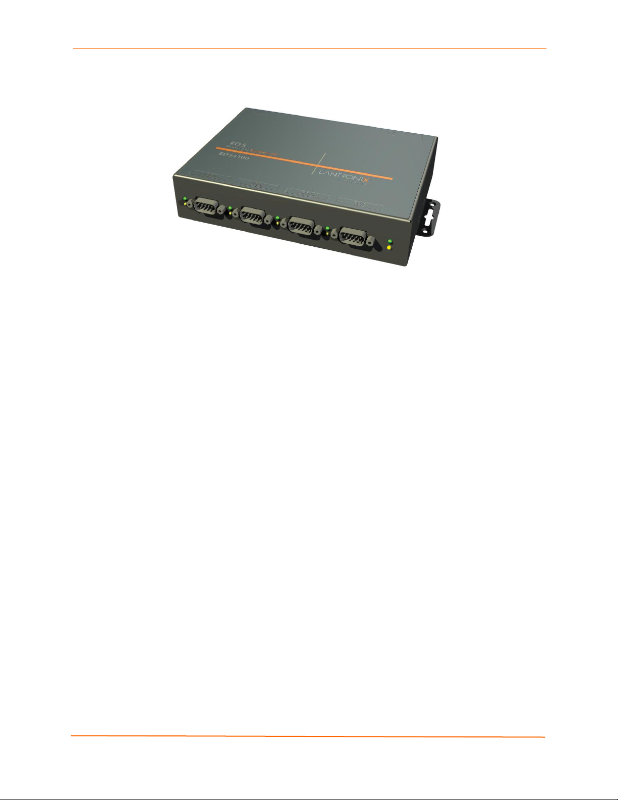
Figure 2-1. EDS4100 4 Port Device Server
Features
The following list summarizes the key features of the EDS4100.
2: Introduction
Includes four serial ports with hardware handshaking signals
Supports RS-232 and RS-422/485
Includes one RJ45 Ethernet port
Supports the IEEE 802.3af standard for Power-over-Ethernet (PoE)
8 MB Flash memory
32 MB Random Access Memory (RAM)
Based on Lantronix’s Evolution OS™
Supports secure data encryption by means of AES, SSH, or SSL sessions
Supports three convenient configuration methods (Web, command line, and
XML)
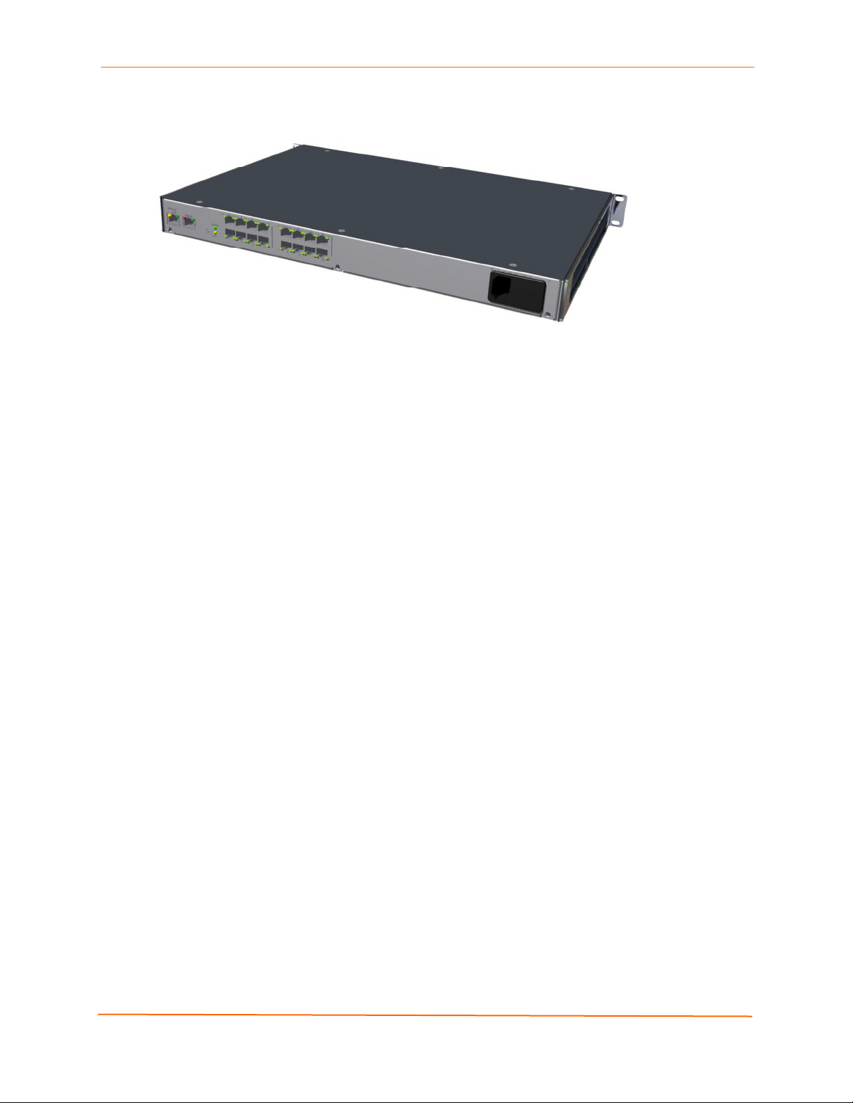
EDS8PR, EDS16PR and EDS32PR Overview
The EDS8PR (8 serial ports), EDS16PR (16 serial ports), and EDS32PR (32 serial ports)
are compact easy-to-use, rack-mountable device servers that give you the ability to
network-enable asynchronous RS-232 serial devices. They provide fully transparent RS232 point-to-point connections without requiring modifications to existing software or
hardware components in your application.
EDS Device Servers User Guide 13
Page 14
2: Introduction
Figure 2-2. EDS16PR Device Server
Features
The following list summarizes the key features of the EDS8PR,, EDS16PR and
EDS32PR.
Includes 8 (EDS8PR), 16 (EDS16PR) or 32 (EDS32PR) serial ports with
hardware handshaking signals
Supports RS-232
Includes one RJ45 Ethernet port
8 MB Flash memory
32 MB Random Access Memory (RAM)
Based on Lantronix’s Evolution OS™
Includes a dedicated console port
Supports secure data encryption by means of AES, SSH, or SSL sessions
Supports three convenient configuration methods (Web, command line, and
XML)
Evolution OS™
EDS device servers incorporate Lantronix’s Evolution OS™. Key features of the
Evolution OS™ include:
Built-in Web server for configuration and troubleshooting from Web-based
browsers
CLI configurability
SNMP management
XML data transport and configurability
Rich Site Summary (RSS) information feeds
Enterprise-grade security with SSL and SSH
Comprehensive troubleshooting tools
EDS Device Servers User Guide 14
Page 15

2: Introduction
Web-Based Configuration and Troubleshooting
Built upon popular Internet-based standards, the EDS enables users to configure,
manage, and troubleshoot efficiently through a simplified browser-based interface that
can be accessed anytime from anywhere. All configuration and troubleshooting options
are launched from a well-organized, multi-page interface. Users can access all
functionality via a Web browser, allowing them flexibility and remote access. As a result,
users can enjoy the twin advantages of decreased downtime (based on the
troubleshooting tools) and the ability to implement configuration changes easily (based
on the configuration tools).
In addition, users can load their own Web pages onto the EDS to facilitate monitoring and
control of their own serial devices that are attached to the EDS.
Command-Line Interface (CLI)
Making the edge-to-enterprise vision a reality, the EDS with the Evolution OS™ uses
industry-standard tools for configuration, communication, and control. For example, the
Evolution OS™ uses a Cisco
similar to that used by data center equipment such as routers and hubs.
®
-like command line interface (CLI) whose syntax is very
SNMP Management
The EDS supports full SNMP management, making it ideal for applications where device
management and monitoring are critical. These features allow networks with SNMP
capabilities to correctly diagnose and monitor EDS device servers.
XML-Based Architecture and Device Control
XML is a fundamental building block for the future growth of M2M networks. The EDS
supports XML-based configuration setup records that makes device configuration
transparent to users and administrators. The XML is easily editable with a standard text
or XML editor.
Rich Site Summary (RSS)
The EDS supports Rich Site Summary (RSS), a rapidly emerging technology for
streaming and managing on-line content. RSS feeds all the configuration changes that
occur on the device. The feed is then read (polled) by an RSS aggregator. More powerful
than simple email alerts, RSS uses XML as an underlying Web page transport and adds
intelligence to the networked device while not taxing already overloaded email systems.
Enterprise-Grade Security
Without the need to disable any features or functionality, the Evolution OS™ provides the
EDS the highest level of security possible. This ‘data center grade’ protection ensures
that each device on the M2M network carries the same level of security as traditional IT
networking equipment in the corporate data center.
With built-in SSH and SSL, secure communications can be established between the EDS
serial ports and the remote end device or application. By protecting the privacy of serial
data being transmitted across public networks, users can maintain their existing
EDS Device Servers User Guide 15
Page 16

2: Introduction
investment in serial technology, while taking advantage of the highest data-protection
levels possible.
SSH and SSL can:
Verify the data received came from the proper source
Validate that the data transferred from the source over the network has not
changed when it arrives at its destination (shared secret and hashing)
Encrypt data to protect it from prying eyes and nefarious individuals
Provide the ability to run popular M2M protocols over a secure SSH connection
In addition to keeping data safe and accessible, the EDS has robust defenses to hostile
Internet attacks such as denial of service (DoS), which can be used to take down the
network. Moreover, the EDS can not be used to bring down other devices on the network.
The EDS can be used with Lantronix’s Secure Com Port Redirector (SCPR) to encrypt
COM port-based communications between PCs and virtually any electronic device.
SCPR is a Windows application that creates a secure communications path over a
network between the computer and serial-based devices that are traditionally controlled
via a COM port. With SCPR installed at each computer, computers that were formerly
“hard-wired” by serial cabling for security purposes or to accommodate applications that
only understood serial data can instead communicate over an Ethernet network or the
Internet.
The EDS also supports a variety of popular cipher technologies including:
Advanced Encryption Standard (AES)
Triple Data Encryption Standard (3DES)
RC4
Hashing algorithms such as Secure Hash Algorithm (SHA-1) and MD5
Troubleshooting Capabilities
The EDS offers a comprehensive diagnostic toolset that lets you troubleshoot problems
quickly and easily. Available from the Web Manager, CLI, and XML interfaces, the
diagnostic tools let you:
View critical hardware, memory, MIB-II, buffer pool, and IP socket information.
Perform ping and traceroute operations.
Conduct forward or backup DNS lookup operations.
View all processes currently running on the EDS, including CPU utilization and
total stack space available.
EDS Device Servers User Guide 16
Page 17

Applications
EDS device servers deliver simple, reliable, and cost-effective network connectivity for all
your serial devices and address the growing need to connect individual devices to the
network over industry-standard Ethernet connections. The EDS is ideal for a variety of
applications, including:
Building automation/security
Industrial automation
Medical/healthcare
Retail automation/point-of-sale
Console management
Traffic management
Building Automation/Security
Automating, managing, and controlling many different aspects of a building is possible
with the EDS. It can overcome the hurdle of stand-alone networks or individual control
systems that are not able to communicate with each other, and not able to share vital
data, in a cost effective way.
2: Introduction
The EDS can also be used to centrally manage equipment and devices over a new or
existing Ethernet network to improve the safety and comfort of building occupants, while
lowering heating, ventilating, air conditioning (HVAC), lighting, and overall energy
operating costs through centralized management and monitoring.
Industrial Automation
Today’s manufacturing facilities face the common challenges of productivity
improvements, inventory management, and quality control. From warehouse to
automotive environments, the need to attach the following devices, whether new or
legacy, continues to grow:
Programmable Logic Controllers (PLCs), Computer Numeric Control and Direct
Numeric Control (CNC/DNC) equipment, process and quality-control equipment
Pump controllers
Bar-code readers and scanners, operator displays, scales, and weighing stations
Printers, machine-vision systems, and other types of manufacturing equipment
The EDS is well suited to deliver network connectivity to all of these devices.
Medical/Healthcare
Hospitals, clinics, and laboratories face rapidly growing needs to deliver medical
information accurately, quickly, and easily, whether at bedside, the nurse’s station, or
anywhere in the facility. The goal to improve healthcare services, however, is balanced
with the need to keep the bottom line from exceeding already constrained budgets.
The EDS can network enable medical equipment and devices using the hospital’s
existing Ethernet network to improve patient care and slash operating costs. This allows
EDS Device Servers User Guide 17
Page 18

2: Introduction
medical staff members to easily monitor and control equipment over the network, whether
it is located at the point of care, in a laboratory, or somewhere else in the building, all
resulting in improved quality of service and reduced operational costs.
Retail Automation/Point-of-Sale
Having the right solution in the store to manage deliveries, track orders, and keep pricing
current are all improvements that the EDS can offer to make retail operations more
successful. From big to small, one store to thousands of outlets, the EDS can empower
point-of-sale (POS) devices to share information across the network effectively.
With the EDS, retailers can increase and streamline productivity quickly and easily by
network-enabling serial devices like card swipe readers, bar-code scanners, scales, cash
registers, and receipt printers.
Console Management
Remote offices can have routers, PBXs, servers and other networking equipment that
require remote management from the corporate facility. The EDS easily attaches to the
serial ports on a server, Private Branch Exchange (PBX), or other networking equipment
to deliver central, remote monitoring and management capability.
Traffic Management
With the ubiquity of Ethernet networks, managing cities over Ethernet is now within
reach. The EDS provides an easy conversion from serial ports on traffic cameras,
billboards, and traffic lights to Ethernet. The EDS obviates the need for long-haul
modems and enables the management of traffic equipment over the network.
EDS Device Servers User Guide 18
Page 19

3: Installation: EDS4100
This chapter describes how to install the EDS4100 device server.
Package Contents
Your EDS4100 package includes the following items:
One EDS4100 device server
One RJ45-to-DB9Fnull modem cable
One product CD that includes this User Guide, the Command Reference, and the
Quick Start guide.
A printed Quick Start guide
Your package may also include a power supply.
User-Supplied Items
To complete your EDS4100 installation, you need the following items:
RS-232 and/or RS-422/485 serial devices that require network connectivity:
− Each EDS4100 serial port supports a directly connected RS-232 serial
device.
− Ports 1 and 3 also support RS-422/485 and can accommodate 31 full-load
RS-485 multi-drop devices or 127 quarter-load RS-485 multi-drop devices
per port, for a total of 62 full-load or 254 quarter-load devices.
A serial cable for each serial device to be connected to the EDS4100. One end of
the cable must have a female DB9 connector to connect to the EDS4100 serial
port. The connector on the other end must be configured for your serial device.
Note: To connect an EDS4100 serial port to another DTE device, you will need a
null modem cable, such as the one supplied in your EDS4100 package. To
connect the EDS4100 serial port to a DCE device, you will need a straightthrough (modem) cable.
An available connection to your Ethernet network and an Ethernet cable.
A working power outlet if the unit will be powered from an AC outlet.
EDS Device Servers User Guide 19
Page 20
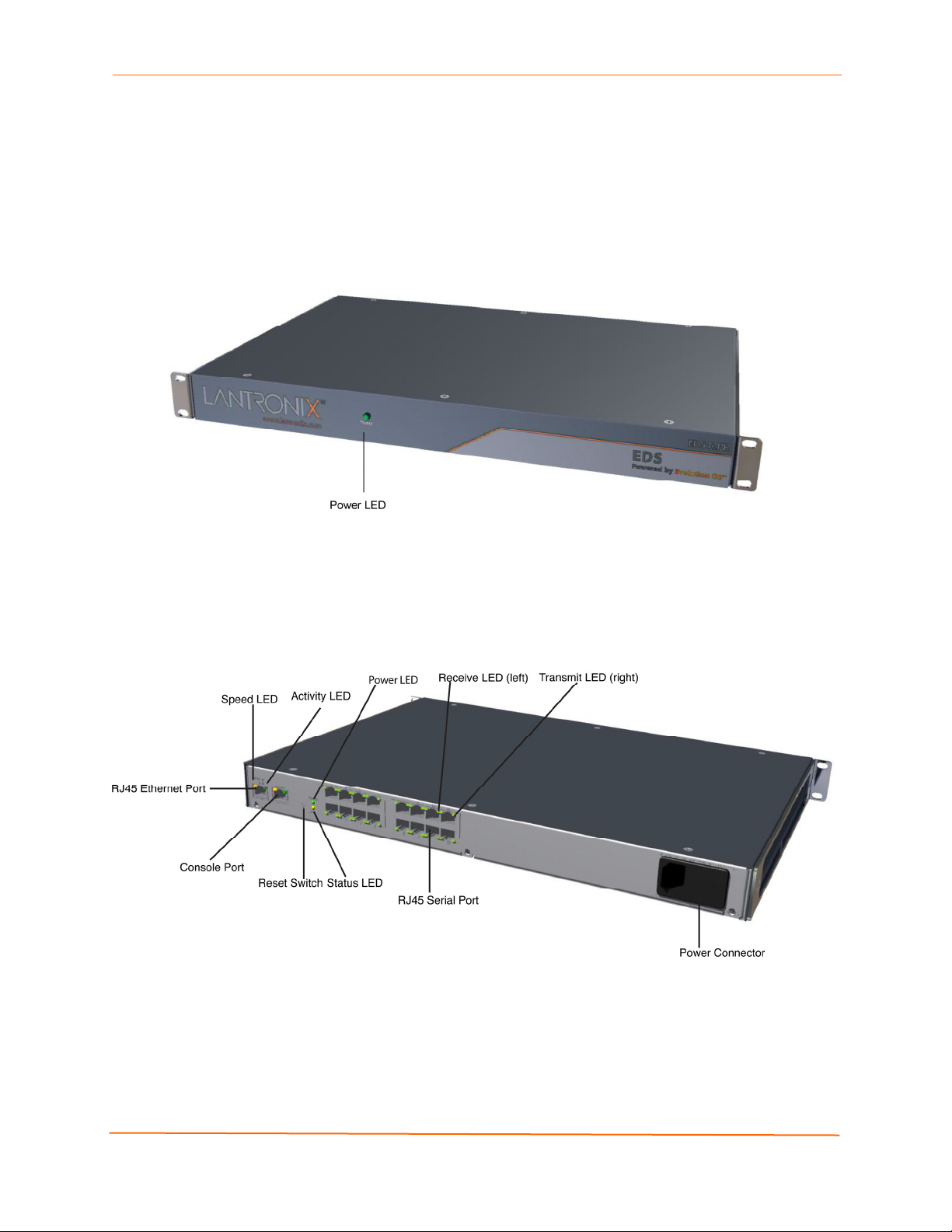
Identifying Hardware Components
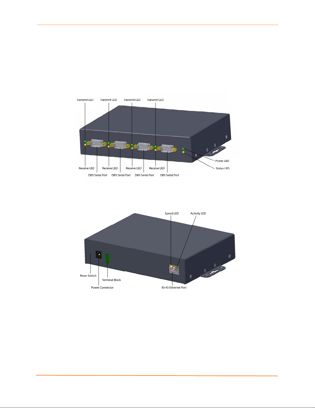
Figure 3-1 shows the hardware components on the front of the EDS4100. Figure 3-2
shows the hardware components on the back of the EDS4100.
Figure 3-1. Front View of the EDS4100
3: Installation: EDS4100
Figure 3-2. Back View of the EDS4100
The bottom of the EDS4100 (not shown) has a product information label. This label
contains the following information:
Bar code
Serial number
Product ID (name)
Product description
Hardware address (also referred to as Ethernet or MAC address)
Agency certifications
EDS Device Servers User Guide 20
Page 21
3: Installation: EDS4100
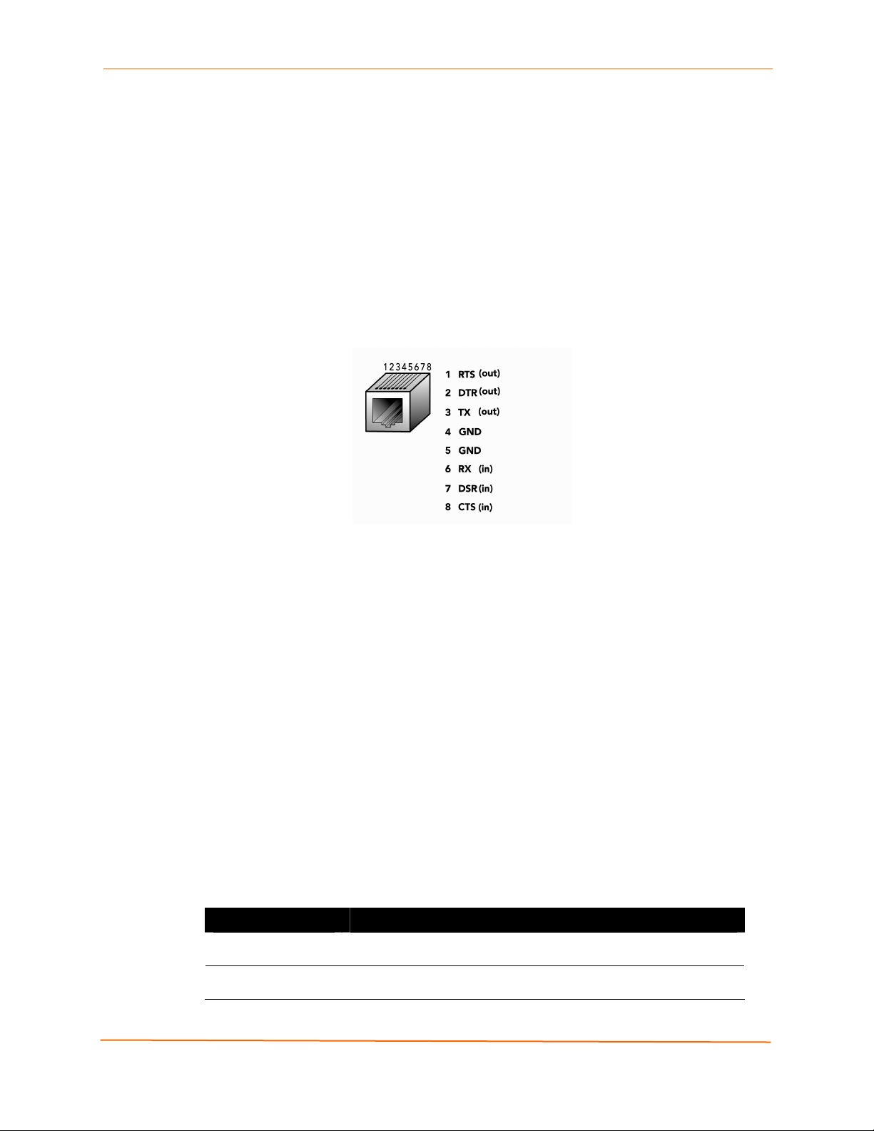
Serial Ports
The front of the EDS4100 has four male DB9 serial ports. These ports allow you to
connect up to four standard serial devices:
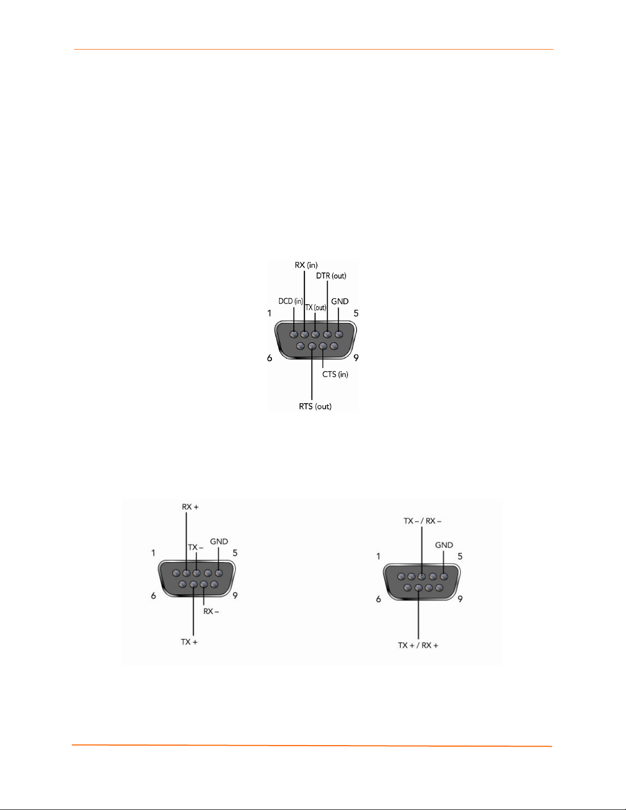
All four serial ports support RS-232 devices. See Figure 3-3 for pin assignments.
Serial ports 1 and 3 also support RS-422 and RS-485 serial devices.
See
Figure 3-4 for pin assignments.
All four serial ports are configured as DTE and support baud rates up to 230,400 baud.
Figure 3-3. RS-232 Serial Port Pins (Serial Ports 1, 2, 3, 4)
Figure 3-4. RS-422/RS-485 Serial Port Pins
RS-422/485 4-wire Pin Assignments
(Serial Ports 1 and 3)
RS-485 2-wire Pin Assignments
(Serial Ports 1 and 3)
Note: Multi-drop connections are supported in 2-wire mode only.
EDS Device Servers User Guide 21
Page 22

3: Installation: EDS4100
Ethernet Port
The back panel of the EDS4100 provides an RJ45 Ethernet port. This port can connect to
an Ethernet (10 Mbps) or Fast Ethernet (100 Mbps) network. The Speed LED on the
back of the EDS4100 shows the connection of the attached Ethernet network. The
EDS4100 can be configured to operate at a fixed Ethernet speed and duplex mode (halfor full-duplex) or auto-negotiate the connection to the Ethernet network.
Terminal Block Connector
The back of the EDS4100 has a terminal block screw connector for attaching to an
appropriate power source, such as those used in automation and manufacturing
industries. The terminal block connector supports a power range from 42 VDC to
56 VDC. It can be used with the EDS4100’s barrel power connector and PoE capabilities
as a redundant power source to the unit.
Figure 3-5. Terminal Block Connector Pin Assignments
Pin Signal
Top V+
Middle V-
Bottom Ground
LEDs
Light-emitting diodes (LEDs) on the front and back panels show status information.
Back panel. Each serial port has a Transmit and a Receive LED. The Ethernet
connector has Speed and Activity LEDs. In addition, the back panel has a Power
LED and a Status LED.
Front panel. The front panel has a green Power LED.
The table below describes the LEDs on the back of the EDS4100.
Figure 3-6 .Back Panel LEDs
LED Description
Transmit (green) Blinking = EDS is transmitting data on the serial port.
Receive (yellow) Blinking = EDS is receiving data on the serial port.
Power (green) On = EDS is receiving power.
Status (yellow) Fast blink = initial startup (loading OS).
Slow blink (once per second) = operating system startup.
On = unit has finished booting.
On = EDS is connected to a 100 Mbps Fast Ethernet network. Speed (yellow)
Off = EDS is connected to a 10 Mbps Ethernet network.
Activity (green) Blink = EDS is sending data to or receiving data from the Ethernet
network.
EDS Device Servers User Guide 22
Page 23

Reset Button
The reset button is on the back of the EDS4100, to the left of the power connector.
Pressing this button reboots the EDS4100 and terminates all data activity occurring on
the serial and Ethernet ports.
Physically Installing the EDS4100
Finding a Suitable Location
Place the EDS4100 on a flat horizontal or vertical surface. The EDS4100 comes
with mounting brackets installed for vertically mounting the unit, for example, on
a wall.
If using AC power, avoid outlets controlled by a wall switch.
3: Installation: EDS4100
Connecting the EDS4100
Observe the following guidelines when attaching serial devices:
All four EDS4100 serial ports support RS-232 devices.
Alternatively, ports 1 and 3 support RS-422/485 devices.
To connect an EDS4100 serial port to another DTE device, use a null modem
cable.
To connect the EDS4100 serial port to a DCE device, use a straight-through
(modem) cable.
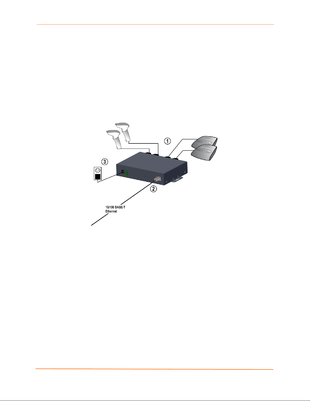
To connect the EDS4100 to one or more serial devices, use the following procedure.
Note: We recommend you power off the serial devices that will be connected to
the EDS4100.
1. For each serial device you want to connect, attach a serial cable between the
EDS4100 and your serial device.
2. Connect an Ethernet cable between the EDS4100 Ethernet port and your Ethernet
network.
3. Use one or more of the following methods to power-up the EDS4100:
PoE method: Power is supplied to the EDS4100 over the Ethernet cable by
either an Ethernet switch or a midspan device.
Barrel power connector: Insert the round end of the supplied power cord into
the barrel power connector on the back of the EDS4100. Plug the other end into
an AC wall outlet. The barrel power connector supports a power range of 9 to 30
VDC.
EDS Device Servers User Guide 23
Page 24
3: Installation: EDS4100
Terminal block connector: Attach the power source to the terminal block
connector on the back of the EDS4100. The terminal block connector supports a
power range of 42 VDC to 56 VDC.
The EDS4100 powers up automatically. After power-up, the self-test begins and
Evolution OS™ starts.
Note: These power-up methods can be used together to provide a redundant
power source to the unit.
4. Power up all connected serial devices.
Figure 3-7. Example of EDS4100 Connections
EDS Device Servers User Guide 24
Page 25

5
4: Installation: EDS8PR, EDS16PR and EDS32PR
This chapter describes how to install the EDS8PR, EDS16PR and EDS32PR device
servers.
Package Contents
Your EDS package includes the following items:
One EDS device server (EDS8PR, EDS16PR or EDS32PR)
One RJ45-to-DB9Fnull modem cable
One product CD that includes this User Guide, the Command Reference, and the
Quick Start guide.
A printed Quick Start guide
Your package may also include a power supply.
User-Supplied Items
To complete your EDS8/16/32PR installation, you need the following items:
RS-232 serial devices that require network connectivity. Each EDS8/16/32PR
serial port supports a directly connected RS-232 serial device.
A serial cable for each serial device to be connected to the EDS8/16/32PR. All
devices attached to the device ports support the RS-232C (EIA-232) standard.
Category 5 cabling with RJ45 connections is used for the device port
connections.
Note: To connect an EDS8/16/32PR serial port to another DTE device,
you need a null modem cable, such as the one supplied in your
EDS8/16/32PR package. To connect the EDS8/16/32PR serial port to a
DCE device, you need a straight-through (modem) cable. For a list of the
Lantronix cables and adapters you can use with the EDS8/16/32PR, see
E: Lantronix Cables and Adapters.
An available connection to your Ethernet network and an Ethernet cable.
A working power outlet if the unit will be powered from an AC outlet.
EDS Device Servers User Guide 2
Page 26
4: Installation: EDS8PR, EDS16PR and EDS32PR
Identifying Hardware Components
Figure 3-1 shows the hardware components on the front of the EDS16PR. Figure 3-2
shows the hardware components on the back of the EDS16PR.
Figure 4-1. Front View of the EDS16PR
Figure 4-2. Back View of the EDS16PR
The bottom of the EDS8/16/32PR has a product information label. This label contains the
following information:
Bar code
Serial number
EDS Device Servers User Guide 26
Page 27
4: Installation: EDS8PR, EDS16PR and EDS32PR
Product ID (name)
Product description
Hardware address (also referred to as Ethernet or MAC address)
Agency certifications
Serial Ports
The EDS8PR has 8 serial ports, the EDS16PR has 16 serial ports, and the EDS32PR
has 32 serial ports. All serial ports are configured as DTE and support baud rates up to
230,400 baud.
Figure 4-3. RJ45 Serial Port
Ethernet Port
The back panel of the EDS8/16/32PR provides an RJ45 Ethernet port. This port can
connect to an Ethernet (10 Mbps) or Fast Ethernet (100 Mbps) network. The Speed LED
on the back of the EDS8/16/32PR shows the connection of the attached Ethernet
network. The EDS8/16/32PR can be configured to operate at a fixed Ethernet speed and
duplex mode (half- or full-duplex) or auto-negotiate the connection to the Ethernet
network.
LEDs
Light-emitting diodes (LEDs) on the front and back panels show status information.
Back panel. Each serial port has a Transmit and a Receive LED. The Ethernet
connector has a Speed and an Activity LEDs. In addition, the back panel has a
Power LED and a Status LED.
Front panel. The front panel has a green Power LED.
The table below describes the LEDs on the back of the EDS.
Back Panel LEDs
LED Description
Transmit (green) Blinking = EDS is transmitting data on the serial port.
Receive (yellow) Blinking = EDS is receiving data on the serial port.
EDS Device Servers User Guide 27
Page 28

4: Installation: EDS8PR, EDS16PR and EDS32PR
LED Description
Power (green) On = EDS is receiving power.
Status (yellow) Fast blink = initial startup (loading OS).
Slow blink (once per second) = operating system startup.
On = unit has finished booting.
On = EDS is connected to a 100 Mbps Fast Ethernet network. Speed (yellow)
Off = EDS is connected to a 10 Mbps Ethernet network.
Activity (green) Blink = EDS is sending data to or receiving data from the Ethernet
network.
Reset Button
The reset button is on the back of the EDS8/16/32PR, to the left of the power connector.
Pressing this button for 2-to-3 seconds reboots the EDS8/16/32PR and terminates all
data activity occurring on the serial and Ethernet ports.
Physically Installing the EDS8/16/32PR
Finding a Suitable Location
You can install the EDS8/16/32PR either in an EIA-standard 19-inch rack (1U
tall) or as a desktop unit.
If using AC power, avoid outlets controlled by a wall switch.
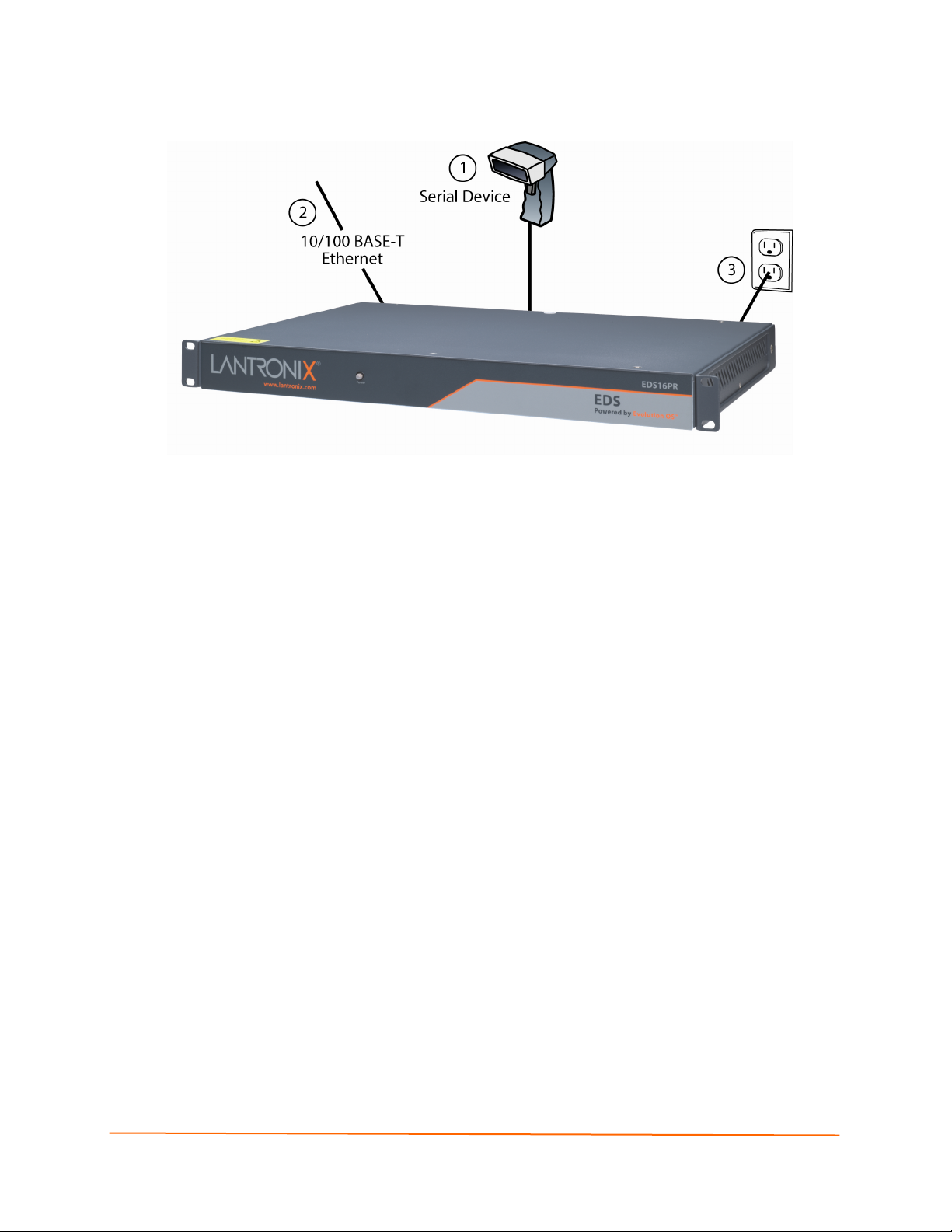
Connecting the EDS8/16/32PR
All serial ports support RS-232 devices.
To connect the EDS8/16/32PR to one or more serial devices, use the following
procedure:
Note: We recommend you power off the serial devices that will be connected to
the EDS8/16/32PR.
1. For each serial device you want to connect, attach a CAT 5 serial cable between the
EDS8/16/32PR and your serial device. For a list of cables and adapters you can use
with the EDS8/16/32PR, see E: Lantronix Cables and Adapters.
2. Connect an Ethernet cable between the EDS8/16/32PR Ethernet port and your
Ethernet network.
3. Insert the supplied power cord into the power connector on the back of the
EDS8/16/32PR. Plug the other end into an AC wall outlet. After power-up, the selftest begins.
4. Power up all connected serial devices.
EDS Device Servers User Guide 28
Page 29
4: Installation: EDS8PR, EDS16PR and EDS32PR
Figure 4-4. Example of EDS16PR Connections
EDS Device Servers User Guide 29
Page 30
0
5: Getting Started
Using DeviceInstaller
The product CD included with your EDS package includes a program called
DeviceInstaller. This program lets you view the properties of the EDS and launch EDS
configuration methods.
Note: You can also assign an IP address and other basic network settings. For
instructions, see the online Help.
Starting DeviceInstaller
Follow the prompts to install DeviceInstaller.
To run DeviceInstaller:
1. From the Windows Start menu, click StartÆPrograms, LantronixÆ
DeviceInstallerÆDeviceInstaller.
2. Click the EDS folder. The list of Lantronix EDS devices available displays.
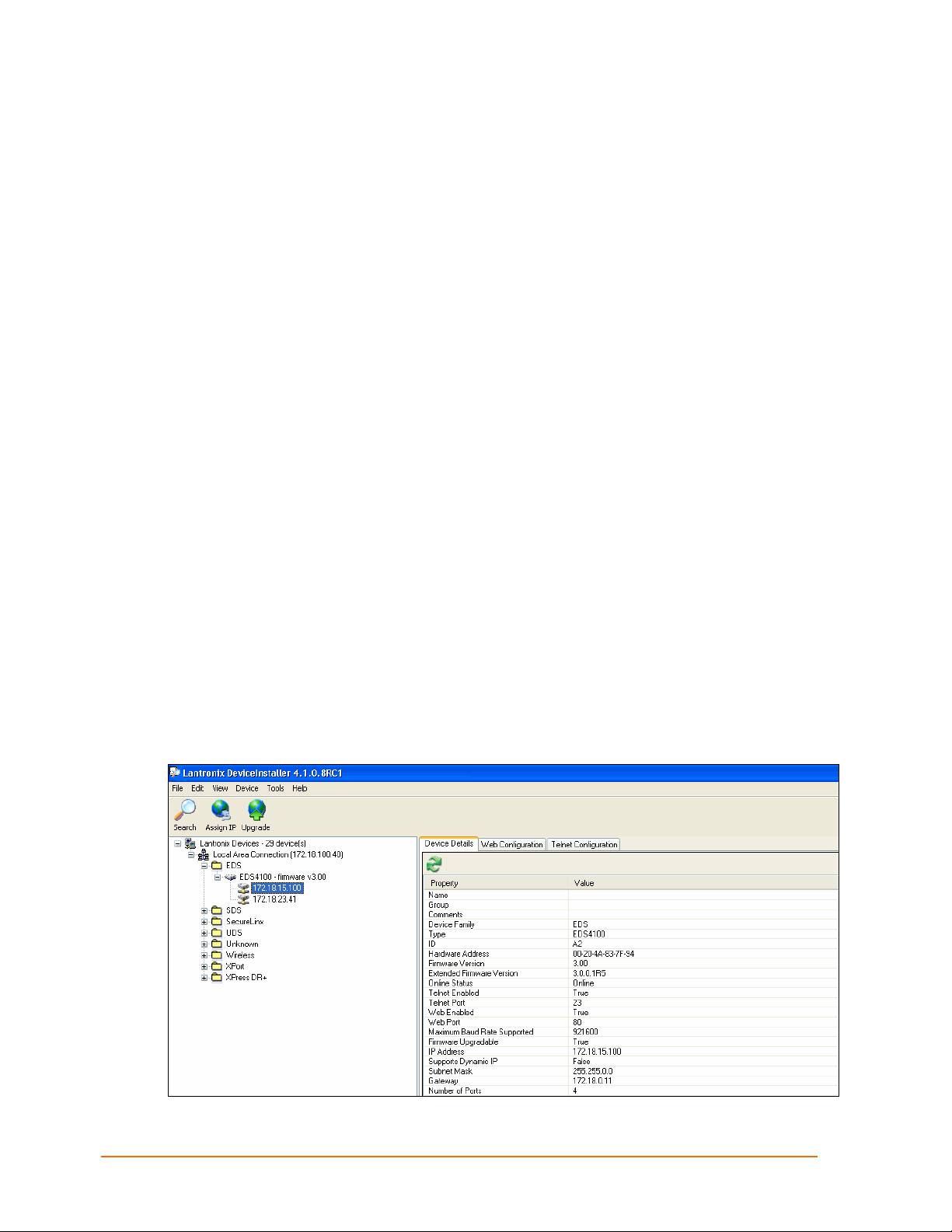
3. Expand the list by clicking the + symbol next to the icon for the desired EDS model.
4. To view the configuration of the EDS, select the unit by clicking its IP address.
Figure 5-1. Lantronix DeviceInstaller
EDS Device Servers User Guide 3
Page 31

5: Getting Started
Viewing EDS Properties
To view the EDS’s properties, in the right window, click the Device Details tab. The
current properties for the EDS display. Figure 5-2 lists the EDS properties and whether
they are user configurable or read only. The properties of the other EDS models are
similar except for the number of ports.
Note: On this screen, you can change Group and Comments. You can only
view the remaining properties. To change them, use one of the EDS
configuration methods described on page 32.
Figure 5-2. EDS4100 Properties
Property Description
Name
Displays the name of the EDS, if configured.
Group
Comments
Device Family Displays the EDS’s device family type as EDS.
Type Displays the device type as EDS.
ID
Hardware Address
Firmware Version
Extended Version
Online Status
Telnet Enabled
Enter a group to categorize the EDS. Double-click
on the field, enter the value, and press Enter to
complete.
Enter comments for the EDS. Double-click on the
field, type in the value, and press Enter to
complete.
Displays the EDS’s ID embedded within the box.
Displays the EDS’s hardware address.
Displays the firmware currently installed on the
EDS.
Displays the full version of firmware currently
installed on the UDS.
Displays the EDS status.
Online = the EDS is online.
Offline = the EDS is offline.
Unreachable = the EDS is on a different subnet.
Busy = the EDS is currently performing a task.
Displays whether Telnet is enabled on this EDS.
Telnet Port
Web Enabled
Web Port
Maximum Baud Rate
Supported
Firmware Upgradeable Displays True if the EDS firmware is upgradeable.
IP Address
Displays the EDS’s port for Telnet sessions.
Displays whether Web Manager access is enabled
on this EDS.
Displays the EDS’s port for Web Manager
configuration.
Displays the EDS’s maximum baud rate.
Note: The EDS may not be operating at this rate.
Displays the EDS’s current IP address. To change
it, click the Assign IP button on the DeviceInstaller
menu bar.
EDS Device Servers User Guide 31
Page 32

Property Description
Supports Dynamic IP Displays True if the EDS automatically receives an
Subnet Mask
Gateway
Number of Ports
Note: These parameters are stored on the computer running DeviceInstaller.
Configuration Methods
When your EDS boots for the first time, it automatically loads its factory-default
configuration settings. For a list of the factory-default configuration settings, see
A: Factory Default Configuration.
For convenience, there are three ways to configure the EDS.
Using the Web Manager interface
5: Getting Started
IP address (e.g., from DHCP). Displays False if
not.
Displays the subnet mask specifying the network
segment on which the EDS resides.
Displays the IP address of the router of this
network. There is no default.
Displays the number of ports on this EDS.
Using the CLI through a SSH/Telnet session or an EDS8/16/32PR serial port.
Using the XML interface
These unified configuration methods provide access to all features, giving you the same
level of control over the EDS8/16/32PR regardless of the configuration method you
choose.
Configuring from the Web Manager Interface
With this method, you can use a Web browser to configure the EDS using a Web-based
graphical point-and-click interface. The advantages to this method are ease of use and
location independence. With this method, you can configure the EDS from any location
that has access to a Web browser and the Internet.
Configuring via an SSH/Telnet Session or Serial Port Using the
CLI
The EDS provides a command-line interface (CLI) designed to enable the configuration
and systems management functions that can also be performed through the Web
Manager and XML interfaces. To configure the EDS using the CLI, you must either start
an SSH or Telnet session or use a terminal or a computer attached to one of the EDS
serial ports or the console port on the EDS8/16/32PR.
The difference between the SSH/Telnet and serial interfaces is the physical connection
paths to the EDS. With an SSH/Telnet session, you can configure the unit without having
to be in the same location as the EDS. The serial-interface method, however, requires a
terminal or computer to be attached to an available EDS serial port. This means the
terminal or computer must be in the same location as the EDS.
For more information, see the EDS Command Reference on the product CD or the
Lantronix web site (www.lantronix.com
).
EDS Device Servers User Guide 32
Page 33

5: Getting Started
Configuring from the XML Interface
The EDS also provides an XML interface that can be used to perform configuration and
systems-management functions. This configuration method lets you automate the
configuration process using XML configuration files. This method is particularly
convenient if you have multiple EDS device servers that will use the same configuration
settings, because you can define a configuration profile that can be imported by, and
shared among, your other EDS device servers.
For more information, see the EDS Command Reference on the product CD or the
Lantronix web site (www.lantronix.com
).
EDS Device Servers User Guide 33
Page 34

6: Configuration Using the Web Manager
This chapter describes how to configure the EDS using the Web Manager, Lantronix’s
browser-based configuration tool. The unit’s configuration is stored in nonvolatile memory
and retained without power. All changes take effect immediately, unless otherwise noted.
Accessing the Web Manager through a Web Browser
The following procedure describes how to log into the EDS using a standard Web
browser.
Note: Alternatively, access the Web Manager by selecting the Web
Configuration tab from DeviceInstaller (see Viewing EDS Properties on
page 31).
To access Web Manager:
1. Open a standard Web browser such as Netscape Navigator 6.x and later, Internet
Explorer 5.5. and later, Mozilla Suite, Mozilla Firefox, or Opera.
2. Enter the IP address of the EDS in the address bar. The EDS’s built-in security
requires you to log in with your user name and password.
Figure 6-1. Prompt for User Name and Password
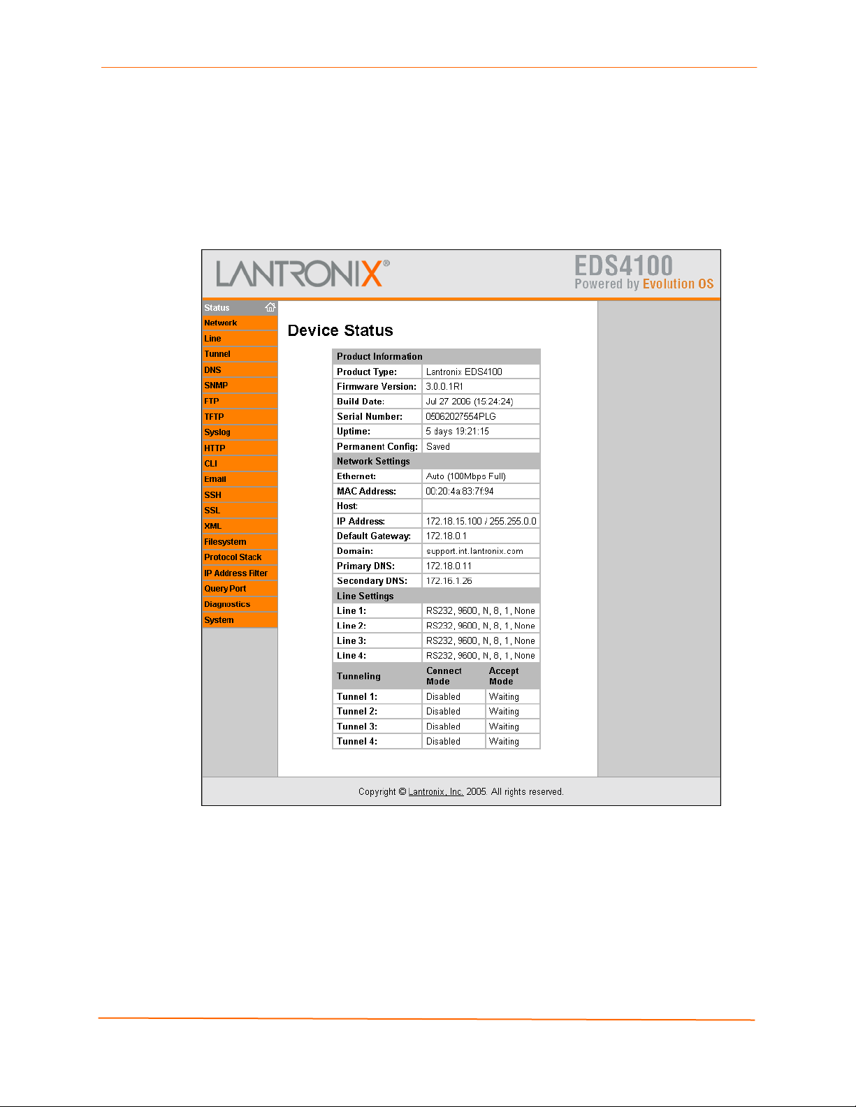
3. Enter your user name and password in the appropriate fields. The Device Status
page displays (see Figure 6-2). This page is the Web Manager home page.
EDS Device Servers User Guide 34
Page 35
6: Configuration Using the Web Manager
Note: The factory-default user name is admin and the factory-default password
is PASS. After you log in to the Web Manager, we recommend you use the FTP
page to change the default FTP password (see page 72), the HTTP
Authentication Page to change the HTTP authentication password (see page 79),
and the Command Line Interface Configuration Page to change the CLI
password (see page 115).
Figure 6-2. Web Manager Device Status Page
EDS Device Servers User Guide 35
Page 36

6: Configuration Using the Web Manager
Navigating Through the Web Manager
The Web Manager provides an intuitive point-and-click interface. A menu bar at the left
side of each page provides links you can click to navigate from one page to another.
Some pages are read-only, while others let you change configuration settings.
Note: There may be times when you must reboot the EDS for the new
configuration settings to take effect. The chapters that follow indicate when a
change requires a reboot.
Figure 6-6 shows the structure of the multilevel Web Manager configuration pages.
Summary of Web Manager Pages
Page Description See
Page
Device
Status
Network Lets you configure the current network interface on the EDS. 44
Line Displays statistics and lets you change the current configuration
Tunnel Displays the current connection statistics and lets you change the
DNS Displays the current configuration of the DNS subsystem and lets
SNMP Displays and lets you change the current Simple Network
FTP Displays statistics and lets you change the current configuration
TFTP Displays statistics and lets you change the current configuration
Syslog Lets you specify the severity of events to log and the server and
HTTP Displays HyperText Transfer Protocol (HTTP) statistics and lets
CLI Displays Command Line Interface (CLI) statistics and lets you
Email Displays email statistics and lets you clear the email log,
SSH Displays and lets you change the configuration settings for SSH
SSL Lets you upload an existing certificate or create a new self-signed
XML Lets you export XML configuration and status records, and import 117
Displays EDS product information and network, line, and
tunneling settings.
and Command mode settings of 4 serial lines for the EDS4100,
16 serial lines for the EDS16PR, and 32 serial lines for the
EDS32PR.
current configuration settings for up to 4 tunnels for the EDS4100,
16 tunnels for the EDS16PR, and 32 tunnels for the EDS32PR.
you change primary and secondary DNS servers.
Management Protocol (SNMP) configuration settings.
for the File Transfer Protocol (FTP) server.
for the Trivial File Transfer Protocol (TFTP) server.
ports to which the syslog should be sent.
you change the current configuration, authentication, and RSS
settings.
change the current CLI configuration settings.
configure email settings, and send an email.
server host keys, SSH server authorized users, SSH client known
hosts, and SSH client users.
certificate.
40
47
52
70
71
72
74
75
75
84
111
111
92
EDS Device Servers User Guide 36
Page 37

6: Configuration Using the Web Manager
Page Description See
Page
XML configuration records.
Filesystem Displays filesystem statistics and lets you browse the filesystem
to create a file or directory, upload files using HTTP, copy a file,
move a file, or perform TFTP actions.
Protocol
Stack
IP Address
Filter
Query Port Displays and lets you change configuration settings for the query
Diagnostics Lets you perform various diagnostic procedures. 95
System Lets you reboot the EDS, restore factory defaults, upload new
Lets you perform lower level network stack-specific activities. 122
Lets you specify all the IP addresses and subnets that are
allowed to send data to this device.
port.
firmware, change the EDS’s long and short names, and change
the time setting.
95
124
109
107
EDS Device Servers User Guide 37
Page 38

6: Configuration Using the Web Manager
Figure 6-3. Web Manager Menu Structure (1 of 4)
(continued on next page)
EDS Device Servers User Guide 38
Page 39

6: Configuration Using the Web Manager
Figure 6-4. Web Manager Menu Structure (2 of 4)
(continued on next page)
EDS Device Servers User Guide 39
Page 40

6: Configuration Using the Web Manager
Figure 6-5. Web Manager Menu Structure (3 of 4)
(continued on next page)
EDS Device Servers User Guide 40
Page 41

6: Configuration Using the Web Manager
Figure 6-6. Web Manager Menu Structure (4 of 4)
EDS Device Servers User Guide 41
Page 42

6: Configuration Using the Web Manager
r
r
Understanding the Web Manager Pages
Figure 6-7 shows the areas of the Web Manager page.
Figure 6-7. Components of the Web Manager Page
Menu Ba
Information
Area
Foote
The header always displays at the top of the page. The header information remains the
same regardless of the page displayed.
The menu bar always displays at the left side of the page, regardless of the page
displayed. The menu bar lists the names of the pages available in the Web Manager. To
display a page, click it in the menu bar.
When you click the name of a page in the menu bar, the page displays in the main area.
The main area of most pages is divided into two sections:
The top section lets you select or enter new configuration settings. After you
change settings, click the Submit button to apply the change. Some settings
require the EDS to be rebooted before the settings take effect. Those settings
are identified in the appropriate sections in this chapter.
The bottom section shows the current configuration.
The information area shows information or instructions associated with the page.
The footer displays at the bottom of the page. It contains copyright information and a link
to the Lantronix home page.
Main Area
EDS Device Servers User Guide 42
Page 43

Device Status Page
The Device Status page is the first page that displays when you log into the Web
Manager. It also displays when you click the Status link in the menu bar. This read-only
page shows the EDS product information, network settings, line settings, and tunneling
settings.
Figure 6-8. Device Status Page (EDS4100)
6: Configuration Using the Web Manager
EDS Device Servers User Guide 43
Page 44

7: Network, Serial Line, and Tunnel Settings
Network Configuration Page
Clicking the Network link in the menu bar displays the Network Configuration page. Here
you can change the following EDS network configuration settings:
BOOTP and DHCP client
IP address, network mask, and gateway
MAC address
Hostname and domain
DHCP client ID
Ethernet transmission speed
EDS Device Servers User Guide 44
Page 45

7: Network, Serial Line, and Tunnel Settings
Figure 7-1. Network Configuration
EDS Device Servers User Guide 45
Page 46

7: Network, Serial Line, and Tunnel Settings
The bottom part of this page shows the current configuration. The After Reboot column
in the Current Configuration section of this page shows the settings that will take effect
the next time the EDS reboots.
Changes to the following settings require the EDS to be rebooted before the new settings
take effect:
BOOTP Client
DHCP Client
IP Address
Network Mask
MAC Address
DHCP Client ID
Notes: Some settings in the Current Configuration section, such as IP
Address and Network Mask have a Delete link you can click to delete the
setting. If you click this link, a warning message asks whether you are sure you
want to delete the setting. Click OK to delete the setting or Cancel to keep it.
Network Configuration Page Settings
Network
Description
Configuration
Page Settings
BOOTP Client Select whether the EDS should send BOOTP requests. Changing this
value requires the EDS to be rebooted. Choices are:
On = EDS sends BOOTP requests on a DHCP-managed network. This
setting overrides the configured IP address, network mask, gateway,
host name, and domain settings. If DHCP is set to On, the EDS
automatically uses DHCP, regardless of whether BOOTP Client is set to
On.
Off = EDS does not send BOOTP requests.
DHCP Client Select whether the EDS IP address is automatically assigned by a DHCP
server. Changing this value requires the EDS to be rebooted. Choices
are:
On = EDS receives its IP address automatically from a DHCP server,
regardless of the BOOTP Client setting. This setting overrides the
configured IP address, network mask, gateway, host name, and domain
settings.
Off = EDS does not receive its IP address automatically.
IP Address Enter the EDS static IP address. The IP address consists of four octets
separated by a period and is used if BOOTP and DHCP are both set to
Off. Changing this value requires the EDS to be rebooted.
Note: When DHCP is enabled, the EDS tries to obtain an IP address
from DHCP. If it cannot, the EDS uses an Auto IP address in the range of
169.254.xxx.xxx.
EDS Device Servers User Guide 46
Page 47

7: Network, Serial Line, and Tunnel Settings
Network
Description
Configuration
Page Settings
Network Mask Enter the EDS subnet mask. The subnet mask consists of four octets
separated by a period. Changing this value requires the EDS to be
rebooted.
Note: When DHCP is enabled, the EDS tries to obtain a network mask
from DHCP. If it cannot, the EDS uses a network mask of 255.255.0.0.
Gateway Enter the router IP address from the local LAN the EDS is on. The
address consists of four octets separated by a period.
MAC Address Enter the EDS MAC address. Default is factory set. Changing this value
may cause unexpected results. Changing this value requires the EDS to
be rebooted.
Hostname Enter the EDS host name. The host name can be up to 31 characters
with no spaces.
Domain Enter the EDS domain name.
DHCP Client ID Enter a DHCP ID if used by the DHCP server. Changing this value
requires the EDS to be rebooted.
Ethernet Link Select the Ethernet link speed. Default is Auto.
Line Settings Pages
The Line Settings page displays the status and statistics for each of the serial lines
(ports). This page also lets you change the character format and command mode settings
for the serial lines.
To select a line:
EDS4100: Click Line 1, Line 2, Line 3, or Line 4 at the top of the page.
EDS8/16/32PR: Select the line from the Select Line drop-down list at the top of the
page.
After you select a serial line, you can click Statistics, Configuration, or Command
Mode to view and change the settings of the selected serial line. Because all serial lines
operate independently, you can specify different configuration settings for each line.
EDS Device Servers User Guide 47
Page 48

7: Network, Serial Line, and Tunnel Settings
Line – Statistics Page
The Line – Statistics page displays when you click Line in the menu bar. It also displays
when you click Statistics at the top of one of the other Line Settings pages. This readonly page shows the status and statistics for the serial line selected at the top of this
page.
Figure 7-2. Line –Statistics Page
EDS Device Servers User Guide 48
Page 49

7: Network, Serial Line, and Tunnel Settings
Line - Configuration Page
If you click Configuration at the top of one of the Line Settings pages, the Line –
Configuration page displays. This page shows the configuration settings for the serial line
selected at the top of the page and lets you change the settings for that serial line.
Figure 7-3. Configuration Page
Configuration Page
Line –
Description
Configuration
Page Settings
Name (optional) Enter a name for the serial port. The name may have up to 25
characters.
Status Select to enable or disable the selected EDS serial port.
Baud Rate Select the baud rate for the currently selected serial port.
Choices are:
300 baud to 230,400 baud. Default is 9600 baud.
Custom = lets you enter in the Custom text box a speed other
than those shown.
EDS Device Servers User Guide 49
Page 50

7: Network, Serial Line, and Tunnel Settings
Line –
Description
Configuration
Page Settings
Parity Select the parity used by the currently selected serial line.
Choices are:
None (default)
Even
Odd
Data Bits Select the number of data bits used by the currently selected
serial line. Choices are:
7
8 (default)
Stop Bits Select the number of stop bits used by the currently selected
serial line. Choices are:
1 (default)
2
Flow Control Select the flow control method used by the currently selected
serial line. Choices are:
None(default)
Hardware
Software
Xon char Character to use to initiate a flow of data.
When Flow Control is set to Software, specify Xon char. Prefix
a decimal character with \ or a hexadecimal character with 0x, or
provide a single printable character. The default Xon char is
0x11.
Xoff char
When Flow Control is set to Software, specify Xoff char. Prefix
a decimal character with \ or a hexadecimal character with 0x, or
provide a single printable character. The default Xoff char is
0x13.
EDS Device Servers User Guide 50
Page 51

7: Network, Serial Line, and Tunnel Settings
Line – Command Mode Page
If you click Command Mode at the top of one of the Line Settings pages, the Line –
Command Mode page displays. This page shows the command mode settings for the
serial line selected at the top of the page and lets you change the settings for that serial
line.
Figure 7-4. Line – Command Mode Page
EDS Device Servers User Guide 51
Page 52

7: Network, Serial Line, and Tunnel Settings
Line – Command Mode Page
Line –
Description
Command
Mode Page
Settings
Mode Select the method of enabling command mode or choose to disable
command mode. Choices are:
Always = immediately enables command mode for the serial line.
Use Serial String = enables command mode when the serial string is
read on the serial line during boot time.
Disabled = Disables command mode.
Wait Time Enter the maximum number of milliseconds the selected serial line waits
to receive the specific serial string at boot time to enter command mode.
Default is 5000 milliseconds.
Serial String Enter the serial string that places the serial line into command mode.
After entering a string, use the buttons to indicate whether the string is a
text or binary value.
Echo Serial
String
Signon
Message
Select whether the serial line echoes the specified serial string at boot
time. Choices are:
Yes = echoes the characters specified in the Serial String text box.
No = does not echo the characters specified in the Serial String text
box.
Enter the boot-up signon message to be sent over the serial line at boot
time. After entering the message, select whether the string is a text or
binary value.
Tunnel Pages
The Tunnel pages let you view and configure settings for tunnels. (For more information,
see Tunneling on page 144.)
To select a tunnel:
EDS4100: Click Tunnel 1, Tunnel 2, Tunnel 3, or Tunnel 4 at the top of the page.
EDS8/16/32PR: Select the tunnel from the Select Tunnel drop-down list at the top of the
page.
After you select a tunnel, you can click Statistics, Serial Settings, Start/Stop Chars,
Accept Mode, Connect Mode, Disconnect Mode, Packing Mode, Modem Emulation,
or AES Keys to view and change the settings of the selected tunnel. Because all tunnels
operate independently, you can specify different configuration settings for each tunnel.
Tunnel – Statistics Page
The Tunnel – Statistics page displays when you click Tunnel in the menu bar. It also
displays when you click Statistics at the top of one of the other Tunnel pages. This readonly page shows the status and statistics for the tunnel currently selected at the top of
this page.
EDS Device Servers User Guide 52
Page 53

7: Network, Serial Line, and Tunnel Settings
Figure 7-5. Tunnel - Statistics Page
Tunnel – Serial Settings Page
If you click Serial Settings at the top of one of the Tunnel pages, the Tunnel – Serial
Settings page displays. This page shows the settings for the tunnel selected at the top of
the page and lets you change the settings. If you change the Buffer Size value, the EDS
must be rebooted for the change to take effect. Changing the other values does not
require a reboot.
EDS Device Servers User Guide 53
Page 54

7: Network, Serial Line, and Tunnel Settings
Under Current Configuration, Buffer Size has a Reset link that lets you reset the buffer
size value shown. If you click this link, a message tells you that you will have to reboot
the EDS. Click OK to proceed or Cancel to cancel the operation.
Figure 7-6. Tunnel – Serial Settings Page
Tunnel – Serial Settings Page
Tunnel –
Description
Serial
Settings Page
Buffer Size Enter the size of the buffer used to receive data on the serial line.
Range = 1 to 4096 bytes. Default is 2048 bytes. Changing this value
requires the EDS to be rebooted.
Read Timeout Enter the maximum number of milliseconds that the EDS waits for
incoming data on the serial line. Default is 200 milliseconds.
Wait for Read
Timeout
Select whether the EDS waits the entire Read Timeout value for incoming
data on the serial line. Waiting occurs even if there is data in the read
buffer ready to be processed. The Read Timeout is ignored only when the
read buffer completely fills with data. Choices are:
Enabled = waits the entire Read Timeout value for incoming data on the
serial line.
Disabled = does not wait the entire Read Timeout value for incoming data
(default).
EDS Device Servers User Guide 54
Page 55

7: Network, Serial Line, and Tunnel Settings
Tunnel – Start/Stop Characters Page
If you click Start/Stop Chars at the top of one of the Tunnel pages, the Tunnel –
Start/Stop Chars page displays. This page shows the start and stop characters used for
the tunnel selected at the top of the page and lets you change the settings for that tunnel.
Figure 7-7. Tunnel – Start/Stop Chars Page
EDS Device Servers User Guide 55
Page 56

7: Network, Serial Line, and Tunnel Settings
Tunnel – Start/Stop Chars Page
Tunnel –
Description
Start/Stop Chars
Page Settings
Start Character Enter the start character. When this character is read on the
serial line, it either initiates a new connection (for a tunnel in
Connect mode) or enables a tunnel in Accept mode to start
listening for connections. Default is <none>.
Stop Character Enter the stop character. When this character is read on the
serial line, it disconnects an active tunnel connection. Default is
<none>.
Echo Start
Character
Echo Stop
Character
Select whether the start character is forwarded (or “echoed’)
through the selected tunnel when the serial line is read. Choices
are:
On = echo the start character on the selected tunnel when the
serial line is read.
Off = do not echo the start character. (default)
Select whether the stop character is echoed through the
selected tunnel when the serial line is read. Choices are:
On = echo the stop character on the selected tunnel when the
serial line is read.
Off = do not echo the stop character. (default)
Tunnel – Accept Mode Page
Accept Mode determines how the EDS “listens” for an incoming connection. If you click
Accept Mode at the top of one of the Tunnel pages, the Tunnel – Accept Mode page
displays. Here you can select the method for starting a tunnel in Accept mode and select
other settings for the tunnel selected at the top of the page.
Under Current Configuration, Local Port has a Reset link if it has been changed from
the default. If you click this link, a message tells you that your action may stop an active
connection. Click OK to proceed or Cancel to cancel the operation.
For more information about Accept mode, see Accept Mode on page 146.
EDS Device Servers User Guide 56
Page 57

7: Network, Serial Line, and Tunnel Settings
Figure 7-8. Tunnel – Accept Mode Page
EDS Device Servers User Guide 57
Page 58

7: Network, Serial Line, and Tunnel Settings
Tunnel – Accept Mode Page
Tunnel –
Description
Accept Mode
Page Settings
Mode Select the method used to start a tunnel in Accept mode. Choices are:
Disabled = do not accept an incoming connection.
Enabled = accept an incoming connection. (default)
Any Character = start waiting for an incoming connection when any
character is read on the serial line.
Start Character = start waiting for an incoming connection when the
start character for the selected tunnel is read on the serial line.
Modem Control Asserted = start waiting for an incoming connection as
long as the Modem Control pin (DSR) is asserted on the serial line until
a connection is made.
Modem Emulation = start waiting for an incoming connection when
triggered by modem emulation AT commands. Connect mode must also
be set to Modem Emulation (see Tunnel – Connect Mode on page 59).
Local Port Enter the number of the local port used to receive (or listen for) packets.
Default is 10001 for Tunnel 1, 10002 for Tunnel 2, and so forth.
Protocol Select the protocol to be used on the connection. Choices are:
TCP (default)
SSH = use this setting if security is a concern. When using SSH, both
the SSH Server Host Keys and SSH Server Authorized Users must be
configured. (See SSH on page 143.)
Telnet
TCP/AES = use for secure tunneling between two EDS’s or software
that supports AES such as the Secure Com Port Redirector. Secure
Com Port Redirector is on the CD that came with your EDS or on the
Lantronix Web Site (www.lantronix.com
Flush Serial Drive Select whether the serial line is flushed when a connection is made.
Choices are:
Enabled = flush the serial line when a connection is made.
Disabled = do not flush the serial line. (default)
Block Serial Data Select whether incoming serial data should be discarded. This setting is
used for debugging purposes. Choices are:
On = discard all incoming serial data on the respective interface.
Off = do not discard all incoming serial data. (default)
Block Network
Data
TCP Keep Alive Specify the number of milliseconds the EDS waits during an inactive
Select whether incoming network data should be discarded. This setting
is used for debugging purposes. Choices are:
On = discard all incoming network data on the respective interface.
Off = do not discard all incoming network data. (default)
connection before checking the status of the connection. If the EDS
does not receive a response from the remote host, it drops that
connection.
).
EDS Device Servers User Guide 58
Page 59

7: Network, Serial Line, and Tunnel Settings
Tunnel –
Description
Accept Mode
Page Settings
Email on Connect Select whether an email is sent when a connection is made.
None = do not send an email.
Email # = send an email corresponding to the tunnel number.
Email on
Disconnect
Password Enter a password that clients must send to the EDS within 30 seconds
Prompt for
Password
Select whether an email corresponding to the tunnel number is sent
when a connection is closed.
None = do not send an email.
Email # = send an email corresponding to the tunnel number.
from opening a network connection to enable data transmission.
The password can have up to 31 characters and must contain only
alphanumeric characters and punctuation. When set, the password sent
to the EDS must be terminated with one of the following: (a) 0x10 (LF),
(b) 0x00, (c) 0x13 0x10 (CR LF), or (d) 0x13 0x00.
Indicate whether the user should be prompted for the password upon
connection.
On = prompt for a password upon connection.
Off = do not prompt for a password upon connection.
Tunnel – Connect Mode Page
Connect Mode determines how the EDS initiates a connection to a remote host or device.
If you click Connect Mode at the top of one of the Tunnel pages, the Tunnel – Connect
Mode page displays. Here you can select the method for starting a tunnel in Connect
mode and select other settings for the tunnel selected at the top of the page.
Any configuration changes you make on the displayed page apply to the tunnel you
selected at the top of this page. For example, if Tunnel 1 is selected, any configuration
changes you make apply to tunnel 1.
Under Current Configuration, both Remote Address and Remote Port have a Delete
link that lets you delete the remote address and port number shown. If you click this link,
a message tells you that your action may stop an active connection. Click OK to proceed
or Cancel to cancel the operation.
For more information about Connect mode, see Connect Mode on page 145.
EDS Device Servers User Guide 59
Page 60

7: Network, Serial Line, and Tunnel Settings
Figure 7-9. Connect Mode Page
EDS Device Servers User Guide 60
Page 61

7: Network, Serial Line, and Tunnel Settings
Tunnel – Connect Mode Page
Tunnel – Connect
Description
Mode Page
Settings
Mode Select the method to be used to start a connection to a remote host
or device. Choices are:
Disabled = an outgoing connection is never started. (default)
Enabled = a connection is attempted until one is made. If the
connection gets disconnected, the EDS retries until a connection is
made.
Any Character = a connection is started when any character is read
on the serial line.
Modem Control Asserted = a connection is attempted as long as the
Modem Control pin (DSR) is asserted until a connection is made.
Start Character = a connection is attempted when the start character
for the selected tunnel is read on the serial line.
Modem Emulation = a connection is started when triggered by
modem emulation AT commands.
Remote Address Enter the address of the remote host to which the selected tunnel will
connect. Default is <none>.
Remote Port Enter the number of the remote port to which the selected tunnel will
connect. Default is <none>.
Local Port Enter the number of the local port that will participate in this tunnel.
Default is Port 1 = 10001, Port 2 = 10002, Port 3 = 10002, and Port 4
= 10004, and so forth.
Protocol Select the protocol to use on the connection. Choices are:
TCP (default)
UDP
SSH = use this setting if security is a concern. This setting requires
you to enter an SSH username.
TCP/AES = use for secure tunneling by means of TCP between two
EDS devices or other devices that support AES.
UDP/AES = use for secure tunneling by means of UDP between two
EDS devices or other devices that support AES.
Reconnect Timer Enter the maximum number of milliseconds to wait before trying to
reconnect to the remote host after a previous attempt failed or the
connection was closed. Default is 15000 milliseconds.
Flush Serial Data Select whether to flush the serial line when a connection is made.
Choices are:
Enabled = flush the serial line when a connection is made.
Disabled = do not flush the serial line. (default)
SSH Username If you selected SSH as the protocol for this tunnel, enter the SSH
client user that is to be used for the SSH connection. Default is
<none>.
EDS Device Servers User Guide 61
Page 62

7: Network, Serial Line, and Tunnel Settings
Tunnel – Connect
Description
Mode Page
Settings
Block Serial Data Select whether incoming block serial data should be discarded. This
setting is used for debugging purposes. Choices are:
On = discard all incoming serial data on the respective interface.
Off = do not discard all incoming serial data. (default)
Block Network Data Select whether incoming block network data should be discarded.
This setting is used for debugging purposes. Choices are:
On = discard all incoming network data on the respective interface.
Off = do not discard all incoming network data. (default)
TCP Keep Alive Specifies the number of milliseconds the EDS waits during an inactive
connection before checking the status of the connection. If the EDS
does not receive a response from the remote host, it drops that
connection.
Email on Connect Select whether email should be sent when a connection is made.
None = no email should be sent.
Email # = send an email corresponding to the tunnel number.
Email on Disconnect Select whether email should be sent when a connection is closed.
None = do not send an email
Email # = send an email corresponding to the tunnel number.
Tunnel – Disconnect Mode Page
If you click Disconnect Mode at the top of one of the Tunnel pages, the Tunnel –
Disconnect Mode page displays. Here you can select the disconnect method for the
tunnel selected at the top of the page. For more information about Disconnect mode, see
Disconnect Mode on page 146.
EDS Device Servers User Guide 62
Page 63

7: Network, Serial Line, and Tunnel Settings
Figure 7-10. Tunnel – Disconnect Mode Page
Tunnel – Disconnect Mode Page
Tunnel –
Description
Disconnect
Mode Page
Settings
Mode Select the method used to disconnect an active tunnel connection.
Choices are:
Disabled = an active connection is never disconnected. (default)
Timeout = an active connection is disconnected after the specified idle
time elapses.
Stop Character = an active connection is disconnected when the
specified stop character is read on the serial line.
Modem Control Not Asserted = an active connection is disconnected
when the Modem Control pin (DSR) is de-asserted on the serial line.
Timeout Enter the idle time, in milliseconds, that must elapse for a connection
before it is disconnected. Default is 60000 milliseconds.
Flush Serial
Data
Select whether the serial line should be flushed when a connection is
disconnected. Choices are:
Enabled = flush the serial line when a connection is disconnected.
Disabled = do not flush the serial line. (default)
EDS Device Servers User Guide 63
Page 64

7: Network, Serial Line, and Tunnel Settings
Tunnel – Packing Mode Page
When tunneling, data can be packed (queued) and sent in large chunks on the network
instead of being sent immediately after being read on the serial line. If you click Packing
Mode at the top of one of the Tunnel pages, the Tunnel – Packing Mode page displays.
Here you can select packing settings for the tunnel selected at the top of the page. For
more information about Packing mode, see Packing Mode on page 147.
Figure 7-11. Tunnel – Packing Mode Page
EDS Device Servers User Guide 64
Page 65

7: Network, Serial Line, and Tunnel Settings
Tunnel – Packing Mode Page
Tunnel – Packing
Description
Mode Page
Settings
Mode Select the method used to pack data. Choices are:
Disabled = data is never packed. (default)
Timeout = data is sent after the timeout elapses.
Send Character = data is sent when the send character is read on
the serial line.
Timeout Enter the maximum number of milliseconds to wait before sending
queued data across the network. Default is 1000 milliseconds.
Threshold Enter the queued data limit that, when reached, immediately sends
queued data to the network. Default is 512 bytes.
Send Character Enter the send character. When this character is read on the serial
line, it forces the queued data to be sent immediately. Default is
<none>.
Trailing Character Enter the trailing character. This character is inserted into the
outgoing data stream immediately after the send character. Default is
<none>.
Tunnel – Modem Emulation Page
A tunnel in connect mode can be initiated using modem commands incoming from the
serial line. If you click Modem Emulation at the top of one of the Tunnel pages, the
Tunnel – Modem Emulation page displays. Here you can select modem emulation
settings for the tunnel selected at the top of the page. For more information about modem
emulation, see Modem Emulation on page 147.
EDS Device Servers User Guide 65
Page 66

7: Network, Serial Line, and Tunnel Settings
Tunnel – Modem Emulation Page
EDS Device Servers User Guide 66
Page 67

7: Network, Serial Line, and Tunnel Settings
Tunnel – Modem Emulation Page
Tunnel – Modem
Description
Emulation Page
Settings
Echo Pluses Select whether the modem plus (+) command is echoed (sent).
Choices are:
On = modem pluses are echoed.
Off = modem pluses are not echoed. (default)
Echo Commands Select whether modem commands are echoed on the serial line.
Choices are:
On = modem commands are echoed. (default)
Off = modem commands are not echoed.
Verbose Response
Codes
Response Codes Select whether modem response (result) codes sent on the serial
Error Unknown
Commands
Connect String If required, enter a customized string that is sent along with the
Select whether modem response (result) codes are sent on the
serial line. Choices are:
Text = modem responses are sent on the serial line. (default)
Numeric = modem responses are not sent.
line take the form of words or numbers. Choices are:
Text = modem responses are sent as words. (default)
Numeric = modem responses are sent as numbers.
Select whether an ERROR or OK response is sent in reply to
unrecognized AT commands. Choices are:
On = ERROR is returned for unrecognized AT commands.
Off = OK is returned for unrecognized AT commands. (default)
CONNECT response code. Default is <none>.
Tunnel – AES Keys Page
Four Advanced Encryption Standard (AES) Encryption Keys are used for tunneling.
Connect mode and Accept mode contain their own sets of keys. One key is used for
encrypting outgoing data and another key is used for decrypting incoming data. These
AES keys are fixed at 16 bytes. Any keys entered that are less than 16 bytes long are
padded with zeroes.
If you click AES Keys at the top of one of the Tunnel pages, the Tunnel – AES Keys
page displays. Here you can enter key data as text or binary values for the tunnel
selected at the top of the page. Binary values are a string of characters representing
hexadecimal or decimal values.
Note: Keys are shared secret keys that must be known by both sides of the
connection and kept secret.
EDS Device Servers User Guide 67
Page 68

7: Network, Serial Line, and Tunnel Settings
Note: Tunneling using AES encryption uses a non-standard protocol and shared
keys, making it not very secure. The EDS also supports SSH as an alternative
method of secure tunneling. SSH tunneling has the advantage of not using
shared keys.
Figure 7-12. Tunnel – AES Keys Page
EDS Device Servers User Guide 68
Page 69

7: Network, Serial Line, and Tunnel Settings
Tunnel – AES Keys Page
Tunnel – AES
Keys Page
Settings
Accept Mode AES
Keys: Encrypt Key
Accept Mode AES
Keys: Decrypt
Key
Connect Mode
AES Keys:
Encrypt Key
Connect Mode
AES Keys:
Decrypt Key
Description
Enter the AES encrypt key for Accept mode. After entering a value,
select an option to specify whether the value is text or binary.
Default is <none>.
Enter the AES decrypt key for Accept mode. After entering a value,
select an option to specify whether the value is text or binary.
Default is <none>.
Enter the AES encrypt key for Connect mode. After entering a
value, select an option to specify whether the value is text or binary.
Default is <none>.
Enter the AES decrypt key for Connect mode. After entering a
value, select an option to specify whether the value is text or binary.
Default is <none>.
EDS Device Servers User Guide 69
Page 70

0
8: Services Settings
DNS Page
Clicking the DNS link in the menu bar displays the DNS page. This page displays
configuration settings for the domain name system (DNS) and lets you change them as
necessary.
The DNS page also shows any contents in the DNS cache. When a DNS name is
resolved using a forward lookup, the results are stored in the DNS cache temporarily.
The EDS consults this cache when performing forward lookups. Each item in the cache
eventually times out and is removed automatically after a certain period, or you can
delete it manually.
Figure 8-1. DNS Page
Note: If the current configuration shows an address comes from DHCP or
BOOTP, the new static address overrides it until you reboot the device.
EDS Device Servers User Guide 7
Page 71

DNS Page
8: Services Settings
DNS Page
Settings
Primary Server Enter the DNS primary server that maintains the master zone
Secondary Server Enter the DNS secondary server that backs up the primary DNS
SNMP Page
Clicking the SNMP link in the menu bar displays the SNMP page. This page is used to
configure the Simple Network Management Protocol (SNMP) agent. Using this page, you
can configure the SNMP service to send a trap when it receives a request for information
that contains an incorrect community name and does not match an accepted system
name for the service.
Under Current Configuration, several settings have a Delete link that lets you delete
these settings. If you click these links, a message asks whether you are sure you want to
delete this information. Click OK to proceed or Cancel to cancel the operation.
Description
information/file for a domain. Default is <none>.
server for a zone. Default is <none>.
Figure 8-2. SNMP Page
EDS Device Servers User Guide 71
Page 72

8: Services Settings
SNMP Page
SNMP Page Settings Description
SNMP Agent Select whether SNMP is enabled. Choices are:
On = SNMP is enabled. (default)
Off = SNMP is disabled.
Read Community Enter the case-sensitive community name from which the
EDS will receive trap messages. Default is public. For
security, the read community name displays as <Configured>
to show that one is enabled.
Write Community Enter the case-sensitive community name to which the EDS
will send trap messages. Default is private. For security, the
write community name displays as <Configured> to show that
one is enabled.
System Contact Enter the name of the system contact. Default is <None>.
System Name Enter the EDS’s name.
System Description Enter a system description for the EDS.
System Location Enter the geographic location of the EDS. Default is <None>.
Enable Traps Select whether SNMP cold start trap messages are enabled
at boot. Choices are:
On = SNMP cold start trap messages are enabled at boot
time. (default)
Off = SNMP traps are disabled.
Primary TrapDest IP Enter the primary SNMP trap host. Default is <None>.
Secondary TrapDest IP Enter the secondary SNMP trap host. Default is <None>.
FTP Page
Clicking the FTP link in the menu bar displays the FTP page. This page displays the
current File Transfer Protocol (FTP) connection status and various statistics about the
FTP server.
Under Current FTP Configuration and Statistics, FTP Password has a Reset link that
lets you reset the FTP password. If you click this link, a message asks whether you are
sure you want to reset this information. Click OK to proceed or Cancel to cancel the
operation.
EDS Device Servers User Guide 72
Page 73

Figure 8-3. FTP Page
8: Services Settings
FTP Page
FTP Page
Description
Settings
FTP Server Select whether the FTP server is enabled. Choices are:
On = FTP server is enabled. (default)
Off = FTP server is disabled.
FTP Username Enter the username required to gain FTP access. Default is admin.
FTP Password Enter the password associated with the username.
EDS Device Servers User Guide 73
Page 74

TFTP Page
Clicking the TFTP link in the menu bar displays the TFTP page. This page displays the
status and various statistics about the Trivial File Transfer Protocol (TFTP) server.
8: Services Settings
Figure 8-4. TFTP Page
TFTP Page
TFTP Page Settings Description
TFTP Server Select whether the TFTP server is enabled. Choices are:
On = TFTP server is enabled. (default)
Off = TFTP server is disabled.
Allow TFTP File
Creation
Select whether the TFTP server can create a file if it does not
already exist. If you enable this feature, it exposes the EDS to
possible Denial-of-Service (DoS) attacks against the filesystem.
Choices are:
On = files can be created by the TFTP server.
Off = files cannot be created by the TFTP server. (default)
EDS Device Servers User Guide 74
Page 75

Syslog Page
Clicking the Syslog link in the menu bar displays the Syslog page. This page shows the
current configuration, status, and statistics for the syslog. Here you can configure the
syslog destination and the severity of the events to log.
8: Services Settings
Figure 8-5. Syslog Page
Syslog Page
Syslog Page
Description
Settings
Host Enter the IP address of the remote server to which system logs
are sent for storage.
Local Port Enter the number of the local port on the EDS to which system
logs are sent.
The system log is always saved to local storage, but it is not
retained through reboots. Saving the system log to a server that
supports remote logging services (see RFC 3164) allows the
administrator to save the complete system log history. The
default is 514.
Remote Port
Enter the number of the port on the remote server that supports
logging services. The default is 514.
EDS Device Servers User Guide 75
Page 76

8: Services Settings
Syslog Page
Settings
Severity to Log From the drop-down box, select the minimum level of system
HTTP Pages
Clicking the HTTP link in the menu bar displays the HTTP Statistics page. This page has
four links at the top for viewing statistics and for viewing and changing configuration,
authentication, and RSS settings.
HTTP Statistics Page
The HTTP Statistics page displays when you click HTTP in the menu bar. It also displays
when you click Statistics at the top of one of the other HTTP pages. This read-only page
shows various statistics about the Hyper Text Transfer Protocol (HTTP) server.
Note: The HTTP log is a scrolling log, with the last Max Log Entries cached and
viewable. To change the maximum number of entries that can be viewed, go to
the HTTP Configuration page (described on page 77).
Description
message the EDS should log. This setting applies to all syslog
facilities. The drop-down list is in descending order of severity
(e.g., Emergency is more severe than Alert.)
Figure 8-6. HTTP Statistics Page
EDS Device Servers User Guide 76
Page 77

8: Services Settings
HTTP Configuration Page
If you click Configuration at the top of one of the HTTP pages, the HTTP Configuration
page displays. Here you can change HTTP configuration settings.
Under Current Configuration, Logs has View and Clear links that let you view or clear
the log. If you click View, the log displays. If you click Clear, a message asks whether
you are sure you want to delete this information. Click OK to proceed or Cancel to cancel
the operation.
Note: For help changing the format of the log, see Log Format Directives in the
information area or on page 79.
Figure 8-7. HTTP Configuration Page
EDS Device Servers User Guide 77
Page 78

HTTP Configuration Page
8: Services Settings
HTTP
Description
Configuration
Page Settings
HTTP Server Select whether the HTTP server is enabled. Choices are:
On = HTTP server is enabled. (default)
Off = HTTP server is disabled.
HTTP Port Enter the number of the port on which the EDS listens for incoming
HTTP connections from a Web browser. Default is 80.
HTTPS Port Enter the number of the port on which the EDS listens for incoming
HTTPS connections from a Web browser. Default is 443. The EDS
listens on the HTTPS port only when an SSL certificate has been
configured for the device (see SSL on page 92).
Max Timeout Enter the maximum number of seconds that the EDS waits for a
request from a client. This value helps prevent Denial of Service
(DoS) attacks against the HTTP Server. Default is 10 seconds.
Max Bytes Enter the maximum number of bytes allowed in a client request. This
value helps prevent Denial of Service (DoS) attacks against the
HTTP Server. Default is 40960 bytes.
Logging Select whether the HTTP log is enabled. Choices are:
On = HTTP log is enabled. (default)
Off = HTTP log is disabled.
Max Log Entries Enter the maximum number of entries that can be cached and
viewed in the HTTP log. The HTTP log is a scrolling log, with only
the last Max Log Entries cached and viewable. Default is 50.
EDS Device Servers User Guide 78
Page 79

8: Services Settings
HTTP
Description
Configuration
Page Settings
Log Format Enter the format of the HTTP log. The log format directives are as
follows:
%a remote IP address (could be a proxy)
%b bytes sent excluding headers
%B bytes sent excluding headers (0 = '-')
%h remote host (same as '%a')
%{h}i header contents from request (h = header string)
%m request method
%p ephemeral local port value used for request
%q query string (prepend with '?' or empty '-')
%t timestamp HH:MM:SS (same as Apache '%(%H:%M:%S)t' or
'%(%T)t')
%u remote user (could be bogus for 401 status)
%U URL path info
%r first line of request (same as '%m %U%q <version>')
%s return status
The maximum length for each directive is 64 bytes. The exception is
'%r' where each element is limited to 64 bytes (i.e. method, URL
path info, and query string). The default log format string is: %h %t
"%r" %s %B "%{Referer}i" "%{User-Agent}i"
HTTP Authentication Page
HTTP Authentication allows you to require usernames and passwords to access specific
web pages or directories on the EDS's built-in web server.
For example, to add web pages to the EDS to control or monitor of a device attached to a
port on the EDS, you can specify the user and password that can access that web page.
If you click Authentication at the top of one of the HTTP pages, the HTTP Authentication
page displays. Here you can change HTTP authentication settings.
Under Current Configuration, URI and Users have a Delete link. If you click Delete, a
message asks whether you are sure you want to delete this information. Click OK to
proceed or Cancel to cancel the operation.
Example:
The following example shows how to add authentication to user-loaded web pages in a
directory called port1control.
1. Create a directory called port1control in the EDS's files system (using an FTP client,
Windows Explorer, or the EDS Web Manager).
2. Copy the custom web pages to this directory.
EDS Device Servers User Guide 79
Page 80

8: Services Settings
3. On the HTTP Authentication page of the EDS Web Manager, add:
A URI of port1control
A Realm of Monitor
An AuthType of Digest
A Username and Password
4. Click the Submit button. The EDS creates a username and password to allow the
user to access all web pages located in the directory port1control in the EDS file
system.
Note: The URI, realm, username, and password are user-specified, freeform
fields. The URI must match the directory created on the EDS file system. The
URI and realm used in the example above are only examples and would typically
be different as specified by the user.
Figure 8-8. HTTP Authentication Page
EDS Device Servers User Guide 80
Page 81

HTTP Authentication Page
8: Services Settings
HTTP
Description
Authentication
Page Settings
URI Enter the Uniform Resource Identifier (URI) of the resource that will
participate in the authentication process. Default is /.
Realm Enter the domain, or realm, used for HTTP operations. Default is
<config>.
AuthType Select an authorization type. Different types of authorization offer
varying levels of security. Choices are (from least to most secure):
None = no authentication necessary.
Basic = encodes passwords using Base64.
Digest = encodes passwords using MD5. (Default)
SSL = page can only be accessed over SSL (no password).
SSL/Basic = page can only be accessed over SSL (encodes
passwords using Base64).
SSL/Digest = page can only be accessed over SSL (encodes
passwords using MD5).
SSL alone does not require a password, but all data transferred to and
from the HTTP Server is encrypted. There is no reason to create an
authentication directive using None, unless you want to override a
parent directive that uses some other AuthType. Multiple users can be
configured within a single authentication directive.
Username Enter the name of the user who will participate in the authentication.
Default is admin.
Password Enter the password that will be associated with the username. Default
is PASS.
EDS Device Servers User Guide 81
Page 82

8: Services Settings
HTTP RSS Page
If you click RSS at the top of one of the HTTP pages, the HTTP RSS page displays. Here
you can specify RDF Site Summary (RSS) information. RSS is a way of feeding online
content to Web users. Instead of actively searching for EDS configuration changes, RSS
feeds allow viewing of only relevant and new information regarding changes made to the
EDS via an RSS publisher.
Under Current Configuration, Data has View and Clear links. If you click View, the data
displays. If you click Clear, a message asks whether you are sure you want to delete this
information. Click OK to proceed or Cancel to cancel the operation.
Figure 8-9. HTTP RSS Page
EDS Device Servers User Guide 82
Page 83

HTTP RSS Page
8: Services Settings
HTTP RSS Page
Description
Settings
RSS Feed Select whether an RSS feed is enabled or disabled. An RSS
syndication feed is served by the HTTP server. This feed contains
up-to-date information about configuration changes that occur on
the EDS. Choices are:
On = RSS feed is enabled.
Off = RSS feed is disabled. (default)
Persistent Select whether the RSS feed is persistent. Choices are:
On = data is stored on the filesystem, in the file “/cfg_log.txt.” This
allows feed data to be available across reboots or until the factory
defaults are set.
Off = data is not stored on the filesystem. (default)
Max Entries Enter the maximum number of log entries. The RSS feed is a
scrolling feed, with only the last Max Entries entries cached and
viewable. To be notified automatically about any configuration
changes that occur, register the RSS feed within your favorite RSS
aggregator. Default is 100.
Each RSS feed entry is prefixed with a timestamp
"[BC:HH:MM:SS]". BC is the Boot Cycle value and indicates the
number of times the EDS has rebooted since factory defaults were
last loaded. The resulting "HH:MM:SS" is the time since the EDS
booted.
EDS Device Servers User Guide 83
Page 84

9: Security Settings
SSH Pages
Clicking the SSH link in the menu bar displays the SSH Server: Host Keys page. This
page has four links at the top for viewing and changing SSH server host keys, SSH
server authorized keys, SSH client known hosts, and SSH client users.
Note: For more information, see SSH on page 143.
SSH Server: Host Keys Page
The SSH Server: Host Keys page displays when you click SSH in the menu bar. It also
displays when you click SSH Server: Host Keys at the top of one of the other SSH
pages. Here you can create new keys and upload them to an SSH server.
SSH server private and public host keys are used by all applications that play the role of
an SSH server, specifically the CLI and tunneling in Accept mode. These keys can be
created elsewhere and uploaded to the device, or automatically generated on the device.
Under Current Configuration, Public RSA Key and Public DSA Key have View and
Delete links if these keys have been created. If you click View, the key displays. If you
click Delete, a message asks whether you are sure you want to delete this information.
Click OK to proceed or Cancel to cancel the operation.
EDS Device Servers User Guide 84
Page 85

Figure 9-1. SSH Server: Host Keys Page
9: Security Settings
EDS Device Servers User Guide 85
Page 86

SSH Server: Host Keys Page
9: Security Settings
SSH Server: Host
Description
Keys Page Settings
Upload Keys
Private Key Enter the path and name of the existing private key you want to
Public Key Enter the path and name of the existing public key you want to
Key Type Select a key type to be used. Choices are:
Create New Keys
Key Type Select a key type to be used for the new key. Choices are:
Bit Size Select a bit length for the new key. Choices are:
upload or use the Browse button to select the key. Be sure the
private key will not be compromised in transit. This implies the
data is uploaded over some kind of secure private network.
upload or use the Browse button to select the key.
RSA = use this key with SSH1 and SSH2 protocols.
DSA = use this key with the SSH2 protocol.
RSA = use this key with the SSH1 and SSH2 protocols.
DSA = use this key with the SSH2 protocol.
512
768
1024
Using a larger bit size takes more time to generate the key.
Approximate times are:
10 seconds for a 512-bit RSA key
1 minute for a 768-bit RSA key
2 minutes for a 1024-bit RSA key
2 minutes for a 512-bit DSA key
10 minutes for a 768-bit DSA key
15 minutes for a 1024-bit DSA key
Some SSH clients require RSA host keys to be at least 1024
bits long.
SSH Client: Known Hosts Page
If you click SSH Client: Known Hosts at the top of one of the SSH pages, the SSH
Client: Known Hosts page displays. Here you can change SSH client settings for known
hosts.
Note: You do not have to complete the fields on this page for communication to
occur. However, completing them adds another layer of security that protects
against Man-In-The-Middle (MITM) attacks.
EDS Device Servers User Guide 86
Page 87

Figure 9-2. SSH Client: Known Hosts Page
9: Security Settings
SSH Client: Known Hosts Page
SSH Client:
Description
Known Hosts
Page Settings
Server Enter the name or IP address of a known host. If you entered a
server name, the name should match the name of the server used
as the Remote Address in Connect mode tunneling.
Public RSA Key Enter the path and name of the existing public RSA key you want
to use with this known host or use the Browse button to select the
key.
Public DSA Key Enter the path and name of the existing public DSA key you want
to use with this known host or use the Browse button to select the
key.
EDS Device Servers User Guide 87
Page 88

9: Security Settings
SSH Server: Authorized Users Page
If you click SSH Server: Authorized Users at the top of one of the SSH pages, the SSH
Server: Authorized Users page displays. Here you can change SSH server settings for
authorized users.
SSH Server Authorized Users are accounts on the EDS that can be used to log into the
EDS via SSH. For instance, these accounts can be used to SSH into the CLI or open an
SSH connection to a device port. Every account must have a password.
The user's public keys are optional and only necessary if public key authentication is
wanted. Using public key authentication allows a connection to be made without the
password being asked.
Under Current Configuration, User has a Delete User link, and Public RSA Key and
Public DSA Key have View Key and Delete Key links. If you click a Delete link, a
message asks whether you are sure you want to delete this information. Click OK to
proceed or Cancel to cancel the operation.
Figure 9-3. SSH Server: Authorized Users Page
EDS Device Servers User Guide 88
Page 89

SSH Server: Authorized Users Page
9: Security Settings
SSH Server:
Description
Authorized Users
Page Settings
Username Enter the name of the user authorized to access the SSH
server.
Password Enter the password associated with the username.
Public RSA Key Enter the path and name of the existing public RSA key you
want to use with this user or use the Browse button to select
the key. If authentication is successful with the key, no
password is required.
Public DSA Key Enter the path and name of the existing public DSA key you
want to use with this user or use the Browse button to select
the key. If authentication is successful with the key, no
password is required.
SSH Client: Users Page
If you click SSH Client: Users at the top of one of the SSH pages, the SSH Client: Users
page displays. Here you can change SSH client settings for users.
SSH client known hosts are used by all applications that play the role of an SSH client,
specifically tunneling in Connect mode. At the very least, a password or key pair must be
configured for a user. The keys for public key authentication can be created elsewhere
and uploaded to the device or automatically generated on the device. If uploading
existing keys, be sure the private key will not be compromised in transit. This implies the
data is uploaded over some kind of secure private network.
Note: If you are providing a key by uploading a file, make sure that the key is not
password protected.
EDS Device Servers User Guide 89
Page 90

Figure 9-4. SSH Client: Users Page
9: Security Settings
EDS Device Servers User Guide 90
Page 91

SSH Client: Users Page
9: Security Settings
SSH Client: Users
Description
Page Settings
Username Enter the name that the EDS uses to connect to the SSH
client user.
Password Enter the password associated with the username.
Remote Command Enter the command that can be executed remotely. Default
is “shell,” which tells the SSH server to execute a remote
shell upon connection. This command can be changed to
anything the remote host can perform.
Private Key Enter the name of the existing private key you want to use
with this SSH client user. You can either enter the path
and name of the key, or use the Browse button to select
the key.
Public Key Enter the path and name of the existing public key you
want to use with this SSH client user or use the Browse
button to select the key.
Key Type Select the key type to be used. Choices are:
RSA = use this key with the SSH1 and SSH2 protocols.
DSA = use this key with the SSH2 protocol.
Create New Keys
Username Enter the name of the user associated with the new key.
Key Type Select the key type to be used for the new key. Choices
are:
RSA = use this key with the SSH1 and SSH2 protocols.
DSA = use this key with the SSH2 protocol.
Bit Size Select the bit length of the new key. Choices are:
512
768
1024
Using a larger Bit Size takes more time to generate the
key. Approximate times are:
10 seconds for a 512-bit RSA key
1 minute for a 768-bit RSA key
2 minutes for a 1024-bit RSA key
2 minutes for a 512-bit DSA key
10 minutes for a 768-bit DSA key
15 minutes for a 1024-bit DSA key
Some SSH clients require RSA host keys to be at least
1024 bits long.
EDS Device Servers User Guide 91
Page 92

SSL Page
Clicking the SSL link in the menu bar displays the SSL page. Here you can upload an
existing SSL certificate or create a new self-signed one.
Note: For more information about SSL, see SSL on page 141.
An SSL certificate must be configured for the HTTP server to listen on the HTTPS port.
This certificate can be created elsewhere and uploaded to the device or automatically
generated on the device. A certificate generated on the device will be self-signed. If
uploading an existing SSL certificate, be sure the private key will not be compromised in
transit. This implies the data is uploaded over some kind of secure private network.
At the bottom of this page is the current SSL certificate, if any. Under Current SSL
Certificate, there is a Delete link. If you click Delete, a message asks whether you are
sure you want to delete the current certificate. Click OK to proceed or Cancel to cancel
the operation.
9: Security Settings
EDS Device Servers User Guide 92
Page 93

Figure 9-5. SSL Page
9: Security Settings
EDS Device Servers User Guide 93
Page 94

SSL Page
9: Security Settings
SSL Page
Description
Settings
Upload Certificate
New Certificate Enter the path and name of the existing certificate you want to
New Private Key Enter the path and name of the existing private key you want to
Create New SelfSigned Certificate
Country (2 Letter
Code)
State/Province Enter the state or province to be assigned to the new self-signed
Locality (City) Enter the city or locality to be assigned to the new self-signed
Organization Enter the organization to be associated with the new self-signed
Organization Unit Enter the organizational unit to be associated with the new self-
Common Name Enter the same name that the user will enter when requesting your
Expires Enter the expiration date, in mm/dd/yyyy format, for the new self-
Bit Size Select the bit size of the new self-signed certificate. Choices are:
upload, or use the Browse button to select the certificate.
upload, or use the Browse button to select the private key.
Enter the 2-letter country code to be assigned to the new selfsigned certificate.
Examples: US for United States and CA for Canada
certificate.
certificate.
certificate.
Example: If your company is called Widgets, and you are setting
up a Web server for the Sales department, enter Widgets for the
Organization.
signed certificate.
Example: If your company is setting up a Web server for the
Sales department, enter Sales for your Organizational Unit.
Web site.
Example: If a user enters http://www.widgets.abccompany.com to
access your Web site, the Common Name would be
www.widgets.abccompany.com.
signed certificate.
Example: An expiration date of May 9, 2007 is entered as
05/05/2007.
512
768
1024
Using a larger bit size takes more time to generate the key.
Approximate times are:
10 seconds for a 512-bit RSA key
1 minute for a 768-bit RSA key
2 minutes for a 1024-bit RSA key
EDS Device Servers User Guide 94
Page 95

10: Maintenance and Diagnostics Settings
Filesystem Pages
Clicking the Filesystem link in the menu bar displays the Filesystem Statistics page. This
page has two links at the top for viewing filesystem statistics and browsing and
manipulating the entire filesystem.
Filesystem Statistics Page
The Filesystem Statistics page displays when you click Filesystem in the menu bar. It
also displays when you click Statistics at the top of the Filesystem Browser page. This
page displays various statistics and current usage information of the flash filesystem.
The Actions row provides Compact and Format links for compacting or formatting the
filesystem. Only a system administrator should perform these tasks.
Note: Compact preserves data and eliminates dirty space by making a new
copy. Format destroys all of the data in the filesystem.
Figure 10-1. Filesystem Statistics Page
EDS Device Servers User Guide 95
Page 96

10: Maintenance and Diagnostics Settings
Filesystem Browser Page
If you click Browse at the top of a Filesystem page, the Filesystem Browser page
displays. Here you can browse and manipulate the entire filesystem. For example, you
can:
Browse the filesystem.
Create files and directories.
Upload files via HTTP.
Copy and move files.
Transfer files to and from a TFTP server.
Figure 10-2. Filesystem Browser Page
EDS Device Servers User Guide 96
Page 97

10: Maintenance and Diagnostics Settings
Filesystem Browser Page
Filesystem
Description
Browser Page
Settings
Create
File Enter the name of the file you want to create, and then click
Directory Enter the name of the directory you want to create, and then
Upload File
Copy File
Source Enter the location where the file you want to copy resides.
Destination Enter the location where you want the file copied. After you
Move
Source Enter the location where the file you want to move resides.
Destination Enter the location where you want the file moved. After you
TFTP
Create.
click Create.
Enter the path and name of the file you want to upload via
HTTP or use the Browse button to select the file, and then
click Upload.
specify a source and destination, click Copy to copy the file.
specify a source and destination, click Move to move the file.
Action Select the action that is to be performed via TFTP. Choices
are:
Get = a “get” command will be executed to store a file locally.
Put = a “put” command will be executed to send a file to a
remote location.
Mode Select a TFTP mode to use. Choices are:
ASCII
Binary
Local File Enter the name of the local file on which the specified “get” or
“put” action is to be performed.
Remote File Enter the name of the file at the remote location that is to be
stored locally (“get’) or externally (“put”).
Host Enter the IP address or name of the host involved in this
operation.
Port Enter the number of the port involved in TFTP operations. Click
Transfer to complete the TFTP transfer.
EDS Device Servers User Guide 97
Page 98

Diagnostics Pages
The EDS has several tools for performing diagnostics. To view these diagnostic tools,
click the Diagnostics link in the menu bar to display the Diagnostics: Hardware page.
The available diagnostic tools appear at the top of the page.
Diagnostics: Hardware Page
The Diagnostics: Hardware page displays when you click Diagnostics in the menu bar. It
also displays when you click Hardware at the top of one of the other Diagnostic pages.
This read-only page displays the current hardware configuration.
10: Maintenance and Diagnostics Settings
EDS Device Servers User Guide 98
Page 99

10: Maintenance and Diagnostics Settings
MIB-II Network Statistics Page
Clicking MIB-II Stats from one of the Diagnostics pages displays the MIB-II Network
Statistics page. This page displays the various SNMP-served Management Information
Bases (MIBs) available on the EDS. Information about these MIBs can be found in the
following Request for Comments (RFCs):
RFC 1213, Original MIB-II definitions
RFC 2011, Updated definitions for IP and ICMP
RFC 2012, Updated definitions for TCP
RFC 2013, Updated definitions for UDP
RFC 2096, Definitions for IP Forwarding
Figure 10-3. MIB-II Network Statistics Page
EDS Device Servers User Guide 99
Page 100

10: Maintenance and Diagnostics Settings
IP Sockets Page
Clicking IP Sockets from one of the Diagnostics pages displays the IP Sockets page.
This read-only page lists all the network sockets on the EDS that are currently open.
Figure 10-4 IP Sockets Page
EDS Device Servers User Guide 100
 Loading...