

Page 1

Part Number PMD-00018
Revision B January 2020
ePACK User Manual
E210 and E220 Series Devices
Page 2

Intellectual Property
© 2019-20 Lantronix, Inc. All rights reserved. No part of the contents of this publication may
be transmitted or reproduced in any form or by any means without the written permission of
Lantronix.
Lantronix is a registered trademark of Lantronix, Inc. in the United States and other countries.
Patented: www.lantronix.com/legal/patents/
Windows and Internet Ex plor er are registered trademarks of Microsoft Corporation. Firefox is
a registered trademark of the Mozilla Foundation. Chrome is a trademark of Google Inc. All
other trademarks and trade names are the property of their respective holders.
Warranty
For details on the Lantronix warranty policy, please go to our web site at
www.lantronix.com/support/warranty/
Contacts
Lantronix, Inc.
7535 Irvine Center Drive, Suite 100
Irvine, CA 92618, USA
Toll Free: 800-526-8766
Phone: 949-453-3990
Fax: 949-453-3995
. Additional patents pending.
Technical Support
Online: www.lantronix.com/support
Sales Offices
For a current list of our domestic and international sales offices, go to the Lantronix web
site at www.lantronix.com/about-us/contact/
Disclaimer
All information contained herein is provided “AS IS.” Lantronix undertakes no obligation to
update the information in this publication. Lantronix does not make, and specifically
disclaims, all warranties of any kind (express, implied or otherwise) regarding title, noninfringement, fitness, quality, accuracy, completeness, usefulness, suitability or
performance of the information provided herein. Lantronix shall have no liability whatsoever
to any user for any damages, losses and causes of action (whether in contract or in tort or
otherwise) in connection with the user’s access or usage of any of the information or
content contained herein. The information and specifications contained in this document
are subject to change without notice.
/
E220 Series Cellular Router User Guide 2
Page 3

Open Source Software
Some applications are Open Source software licensed under the Berkeley Software
Distribution (BSD) license, the GNU General Public License (GPL) as published by the
Free Software Foundation (FSF), or the Python Software Foundation (PSF) License
Agreement for Python 2.7.3 (Python License). Lantronix grants you no right to receive
source code to the Open Source software; however, in some cases, rights and access to
source code for certain Open Source software may be available directly from Lantronix’
licensors. Your use of each Open Source component or software is subject to the terms of
the applicable license. The BSD license is available at http://opensource.org/licenses
GNU General Public License is available at http://www.gnu.org/licenses/. The Python
License is available at http://cmpt165.csil.sfu.ca/Python-Docs/license.html. Your use of
each Open Source component or software is subject to the terms of the applicable license.
OPEN SOURCE SOFTWARE IS DISTRIBUTED WITHOUT ANY WARRANTY,
INCLUDING ANY IMPLIED WARRANTY OF MERCHANTABILITY OR FITNESS FOR A
PARTICULAR PURPOSE. SEE THE APPL IC ABLE LICENSE AGRE EMENT FOR
ADDITIONAL INFORMATION.
You may request a list of the open source components and the licenses that apply to them.
Contact your regional Lantronix sales associate. www.lantronix.com/about-us/contact/
. The
Revision Histor y
Date Rev. Comments
March 2017 2.2.0
February 2018 2.3
October 2019 A Added Lantronix document part number, Lantronix logo, branding,
January 2020 B Renamed document to ePack User Manual.
For the latest revision of this product document, please check our online documentation at
www.lantronix.com/support/documentation
contact information, and links.
ePack firmware for E210 and E220 series devices, version 2.3
.
E220 Series Cellular Router User Guide 3
Page 4

Table of Contents
Overview ......................................................................................................... 7
Prerequisite ..................................................................................................... 9
Default Configuration ..................................................................................... 10
LED Behavior ................................................................................................. 11
Logon Procedure ............................................................................................ 14
Common Icons and Buttons ............................................................................ 15
Quick Setup ................................................................................................... 16
Status ............................................................................................................ 19
Status ............................................................................................................................ 19
IPv4 Firewall .................................................................................................................. 31
IPv6 Firewall .................................................................................................................. 33
Wireless ........................................................................................................................ 38
Load .............................................................................................................................. 40
Traffic ............................................................................................................................ 41
Connection .................................................................................................................... 46
System .......................................................................................................... 48
General Settings ............................................................................................................ 48
Logging .......................................................................................................................... 50
Language and Style ....................................................................................................... 52
Router Password ........................................................................................................... 53
SSH Access .................................................................................................................... 54
E220 Series Cellular Router User Guide 4
Page 5
Actions .......................................................................................................................... 56
Configuration ................................................................................................................ 59
Flash Operation............................................................................................................. 60
Network ........................................................................................................ 64
Interface Overview ....................................................................................................... 69
3G (Only for E205) ........................................................................................................ 73
CELLDHCP (Only for E206) ............................................................................................ 78
CELLULAR ...................................................................................................................... 82
WAN .............................................................................................................................. 86
LAN ................................................................................................................................ 91
WWAN ........................................................................................................................ 100
Overview ..................................................................................................................... 106
Configuration .............................................................................................................. 108
Advanced Settings ...................................................................................................... 120
Add .............................................................................................................................. 127
General Settings .......................................................................................................... 136
Resolv and Host file .................................................................................................... 138
TFTP Settings ............................................................................................................... 139
Advanced Settings ...................................................................................................... 140
General Setting ........................................................................................................... 146
Port Forwarding .......................................................................................................... 151
Traffic Rules ................................................................................................................ 152
Custom Rules .............................................................................................................. 155
Services ....................................................................................................... 156
PPTP ............................................................................................................................ 158
IPSec (Internet Protocol Security) ............................................................................... 162
L2TP ............................................................................................................................ 173
E220 Series Cellular Router User Guide 5
Page 6
GRE ............................................................................................................................. 176
OpenVPN .................................................................................................................... 178
SMS Configuration ...................................................................................................... 182
Ethernet SMS .............................................................................................................. 184
LAN .............................................................................................................................. 192
WAN ............................................................................................................................ 192
Cellular ........................................................................................................................ 194
Wi-Fi ............................................................................................................................ 195
GPS .............................................................................................................................. 196
Sending Data ............................................................................................................... 196
Data Sending Format .................................................................................................. 197
Wiring Diagrams .......................................................................................... 211
List of Acronym ............................................................................................ 212
E220 Series Cellular Router User Guide 6
Page 7

MODEL
T
OPERATOR(S)
EMEA, [most of]
Asia Pacific
EMEA
LTE
cat. 1
3/8/20
E224#38K##38
Asia Pacific
3/5/8/28
3G b
1/5/8
RCM, NCC
E224#358S#158
EMEA, [most of]
Asia Pacific
World
1/2/5/8
2/3/5/8
JPA, JRF, NBTC
E225
EMEA
1/3/7/8/20/28
3G c; 2G
1/8; 3/8
RED, GCF
Apr. ’18
E228MKII#02
Asia Pacific
1/3/5/7/8/28
3G c
1/5/8
RCM, KCC, NCC
May ’18
E228MKII#04
1/3/5
TDD 40/41**
AT&T Wireless, Rogers
Verizon Wireless
2/4/5/17
4/13
3G c
2/5
N/A
Concurrent GPS,
Galileo and either
GLONASS (factory
setting) or Beidou
IC, FCC, PTCRB,
Verizon Wireless
NAME
E225 Lite
E224
E225
Overview
Overview
With high-speed cel lular (3 G and be yond), WAN, LAN and W i-Fi connectivit y, the Lantronix’s e-series
of routers are highly versatile, reliable and rugged router designed for mission-critical M2M and
enterprise applications requiring faultless connectivity. Cel lular can be configured to be the primar y
connectivity mode or the W AN f ailover a lternati ve to a wire line c onnect ion. T h e y also supp ort a wide
range of advanced routing protocols and VPN configurations.
This manual covers the following products:
• Lantronix E228
• Lantronix E225LITE#02
• Lantronix E225LITE
• Lantronix E224
• Lantronix E215#02
• Lantronix E214
• Lantronix E218
• Lantronix E205XT02
• Lantronix E205XT04
• Lantronix E206XT
The below table mentions the various available SKUs:
E220 Series
ERRITORIES
OR
CELLULAR
TYPE
3G a 1/8
3G a
BANDS
1/8
FALLBACK
MODE(S)
2G 3/8
2G
BANDS GNSS
PLANNED
CERTIFICATIONS
same as
E228’s
3/8 RED, GCF E225#02
RED, GCF
FCS
(*)
ORDER
CODE
E225LITE#02
E228 Mk II
E228
IZat
gen. 8C
gpsOne
AT&T Wireless,
RCM, NCC E228#37S
JPA, JRF
E228#245DH#25
E228#1JL
China, India
User-configurable to
Asia Pacific 3/7/28
NTT docomo 1/19/21
KDDI 1/11/18 E228#1BI
South Korea 1/3/5/7 KCC E228#1357
LTE
cat. 4
3G c; 2G 1/8; 3/8 CCC, NAL, SRRC Sep. ’18 E228MKII#078
N/A
Please consult us regarding the models or features shown in grey which are factory options subject to MOQ and other considerations
Uplink / Downlink maximum data rates – 3G: 5.76 /
– LTE cat. 1: 5 / 10 Mbps (FDD); 3.1 / 8.96 Mbps (TDD) ** TDD B41 contains TDD B38
– LTE cat. 4: 50 / 150 Mbps (FDD); 35 / 130 Mbps (TDD)
(a)
7.2; or
(b)
10.1; or
(c)
42.2 Mbps* First customer shipment
E220 Series Cellular Router User Guide [Type here] 7
Page 8

MODEL
T
OPERATOR(S)
F
MODE(S)
2-mode
NB-IoT
1/2/3**/4/
20/26****/28
EMEA
1/3/7/8/20/28
3G c; 2G
1/8; 3/8
RED, GCF
E214#02
Asia Pacific
3**/5/8/28
3G b
1/5/8
RCM, NCC
E214#358S#158
1/3/5
TDD 40/41
same as
E214G’s
FCC,
Verizon Wireless
AT&T Wireless,
T-Mobile USA, Sprint
IC, FCC, PTCRB,
AT&T Wireless
EMEA, [most of]
Asia Pacific
Israel, Australia & New
Thailand
NTT docomo
LTE
cat. 4
1/19/21
E218#1JL
KDDI
1/11/18
E218#1BI
NAME
Overview
E210 Series
ERRITORIES
OR
CELLULAR
TYPE
BANDS
ALL
BACK
BANDS GNSS
PLANNED
CERTIFICATIONS
FCS
(*)
ORDER
CODE
E213 World
E214
E214G
E215
E216
E218
China, India
Verizon Wireless 4/13
Zealand, NTT docomo,
LTE-M1 /
LTE
cat. 1
3G a 1/8 2G 3/8
3G b 1/5/8
8/12***/13/
2/4/5/12*** 3G c 2/4/5
2G 2/3/5/8
3G c; 2G 1/8; 3/8
N/A
N/A
same as
E214G’s
IZat
gen. 8C
gpsOne
TBD
CCC, NAL, SRRC Sep. ’18 E214#078
RED, GCF E215#02
NBTC, Postel E216
JPA, JRF
Apr. ’18
Apr. ’18
Please consult us regarding the models or features shown in grey which are subject to MOQ and other
considerations
Uplink / Downlink maximum data rates – 3G: 5.76 /
– NB-IoT: 62.5 / 27.2 kbps; LTE-M1: 375 / 375 kbps ** B3 contains Japan’s B9 *** B12 contains B17
– LTE cat. 1: 5 / 10 Mbps (FDD); 3.1 / 8.96 Mbps (TDD) **** B26 contains (i) KDDI’s B18; and (ii) NorAm’s B5
– LTE cat. 4: 50 / 150 Mbps (FDD); 35 / 130 Mbps (TDD) which contains NTT docomo’s B19 which contains Japan’s B6
(a)
7.2; or
(b)
10.1; or
(c)
42.2 Mbps * First customer shipment
Note
• Except when explicitly mentioned, all the screenshots in this user guide are taken
from a Lantronix E225 unit.
E213
E214G#01
E214G#00
E220 Series Cellular Router User Guide 8
Page 9

Prerequisite
Prerequisite
Before continuing with the inst allation of your E2XX Series router, m ake sur e you have a n active SI M
card and a computer equipped with the following:
• Ethernet port or Wi-Fi connectivity and Internet service
• Web browser such as Int ernet Explorer 10+ or Google Chr ome 30+, Mo zilla Firefox 20+ or
Apple Safari 4+ to access the Lantronix Web Admin Console
• DHCP client enabled in the computer to obtain a valid IP Address from router.
A. How to Enable DHCP in Windows?
• Navigate to Start > Control Panel > Network and Sharing Centre > Click the existing
Connection > Network Connection Status dialog box appears > click Properti es > Double
click Internet Protocol Version 4 (TCP/IPv4) > Internet Protocol Version 4 (TCP/IPv4)
Properties dialog box appears > Under tab General, select following options:
a. Obtain an IP address automatically
b. Obtain DNS server address automatically
E220 Series Cellular Router User Guide 9
Page 10
Default Configuration
Default Configura ti on
Note
• All the Username and Password are case sensitive.
Web Admin Page
Parameters Details
IP Address (LAN) 192.168.1.1
Username admin
Password Admin
Table 3.1-1: Default Web Admin Page Credentials
Wi-Fi enabled, with WPA/WPA2 TKIP key
Parameter Details
SSID Maestro E200
WPA Key W1rele$$
Table 3.2-1: Default Wi-Fi Credentials (WPA/WPA TKIP)
Default Basic Configuration
• WAN (Ethernet) Connection – Automatic (DHCP client)
• LAN (Ethernet) Active DHCP with starting IP Address: 192. 168. 1.1 00 with po ol of 100 client s.
• WAN as priority source of Internet with Cellular backup
• Cellular default Access Point Name (APN) is “internet” and no PAP / CHAP Authentication
• Wi-Fi is on with SSID Maestro EXX as an access point
E220 Series Cellular Router User Guide 10
Page 11
LED Behavior
LED Behavior
• Ethernet port (WAN and LAN)
• Amber LED (Link Indicator) – When ON indicates the valid link detection
(10/100Mbps).
• Green LED (Activity indicator) – When On (Blinking) indicates traffic/data activity on
the port.
• Other LEDs – For E200 and E220 Series
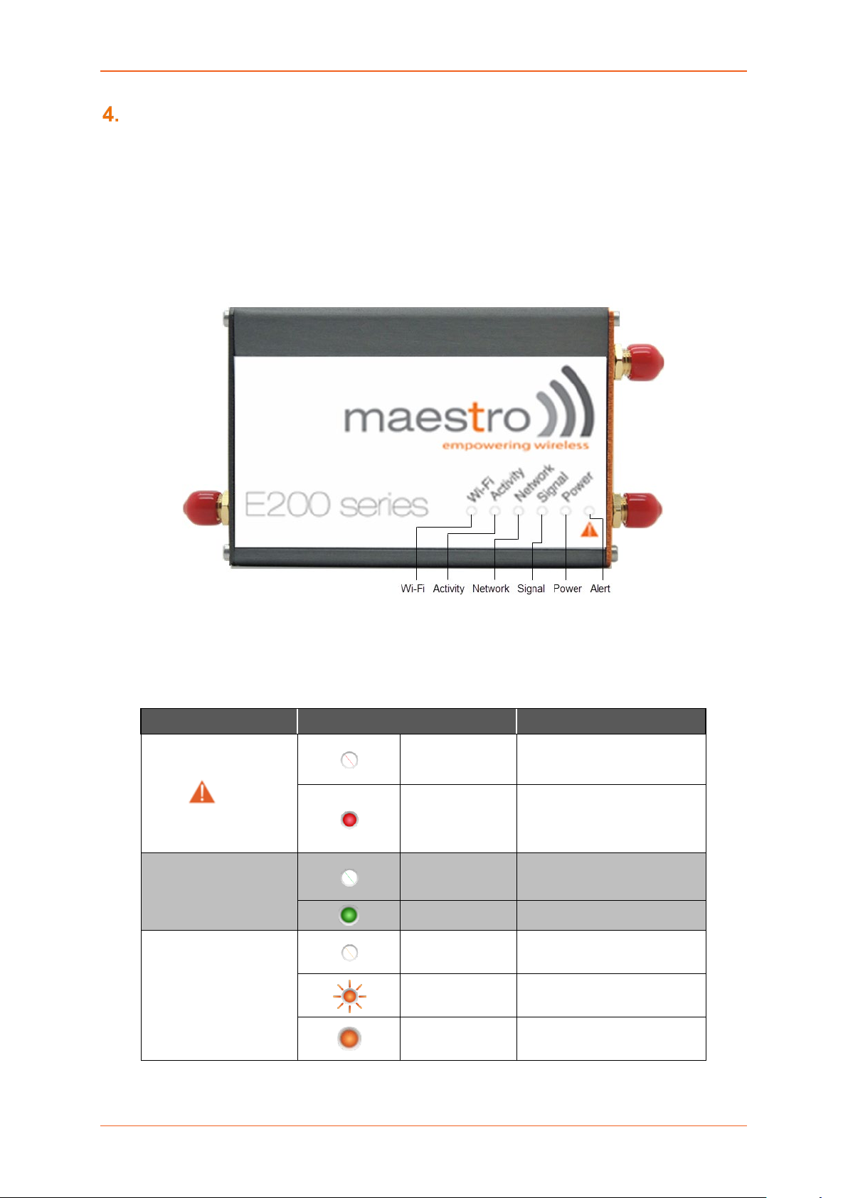
Figure 3.3-1: Front Panel
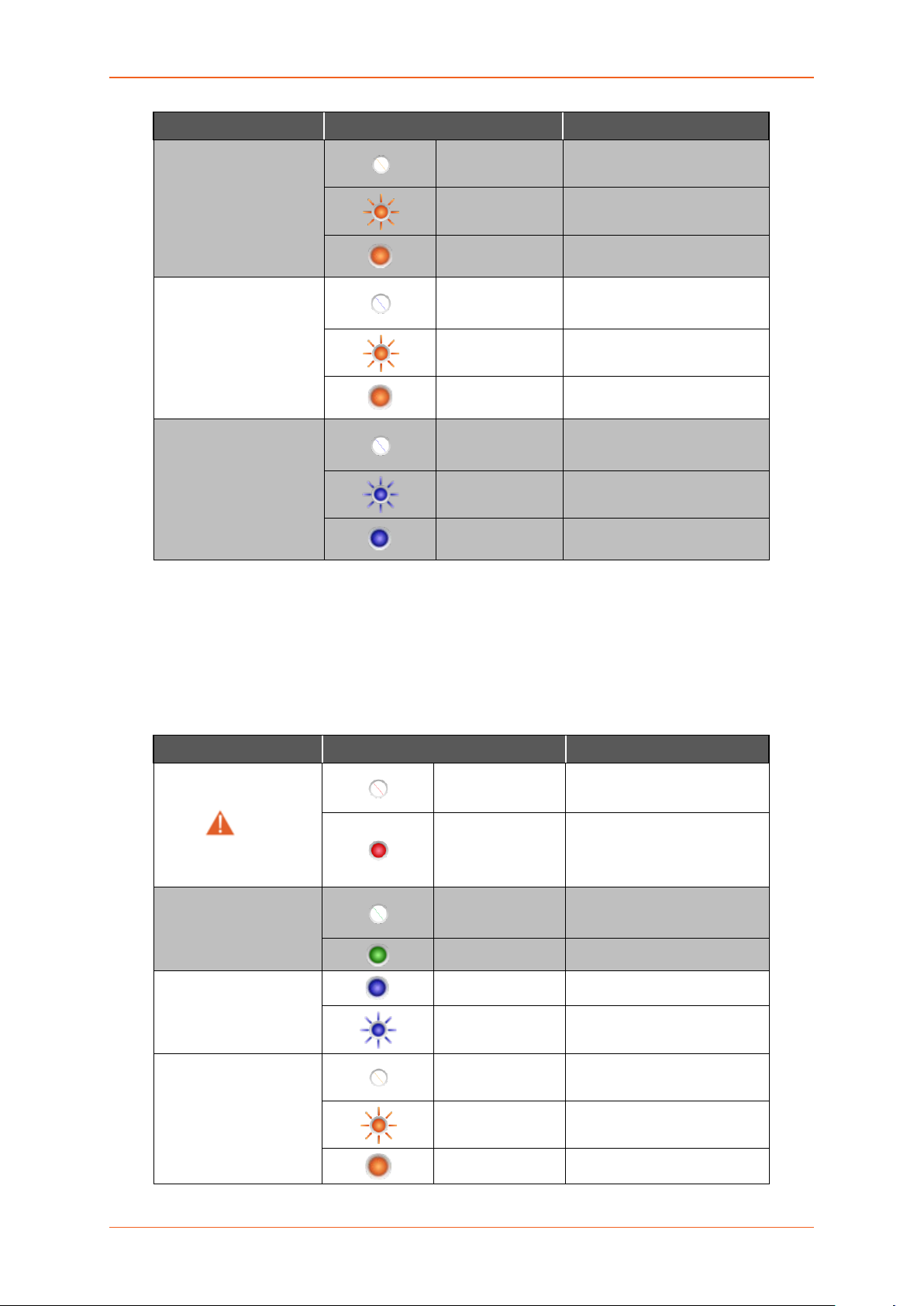
The top panel of Lantronix E20 0 and E220 Series R outers features 6 LEDs on the fr ont to indicate
critical system information.
Name Colour and State Description
No alert, device is running
smoothly
Hardware fault (high
temperature or problem with
module), Cellular Module
reboot, Linux Kernel booting
No signal
(CSQ=0 to 5, 97, 98, 99)
Weak signal
(CSQ > 6 to 12)
Alert
Power
Signal
OFF
Red ON
OFF Power off
Green ON Power on
OFF
Amber Flashing
Amber ON
Strong signal
(CSQ >12)
E220 Series Cellular Router User Guide 11
Page 12
LED Behavior
Name Colour and State Description
Not registered on a cellular
network.
Registered on a roaming
cellular network
Registered on home cellular
network
Cellular data service is not
connected
Data Transfer over Cellular
Network
Cellular data service is
connected
Wi-Fi network is up and
activated
Network
Activity
WI-FI
OFF
Amber Flashing
Amber ON
OFF
Amber Flashing
Amber ON
OFF Wi-Fi network is inactive
Blue Flashing Traffic on Wi-Fi network
Blue ON
Table 3.3-1: LED States and Description
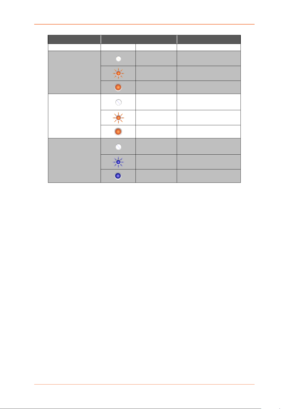
• Other LEDs – For E210 Ser ies
The top panel of Lantronix E200 and E220 Series Router s features 7 LEDs on the front to
indicate critical system information.
Name Colour and State Description
Alert
Power
SIM in use
Signal
OFF
Red ON
OFF Power off
Green ON Power on
On SI M 1
Flashing SIM 2
OFF
Amber Flashing
Amber ON Strong signal
No alert, device is running
smoothly
Hardware fault (high
temperature or problem with
module), Cellular Module
reboot, Linux Kernel booting
No signal
(CSQ=0 to 5, 97, 98, 99)
Weak signal
(CSQ > 6 to 12)
E220 Series Cellular Router User Guide 12
Page 13
LED Behavior
(CSQ >12)
Name Colour and State Description
Network
Activity
WI-FI
Table 3.3-2: LED States and Description
OFF
Amber Flashing
Amber ON
OFF
Amber Flashing
Amber ON
OFF Wi-Fi network is inactive
Blue Flashing Traffic on Wi-Fi network
Blue ON
Not registered on a cellular
network.
Registered on a roaming
cellular network
Registered on home cellular
network
Cellular data service is not
connected
Data Transfer over Cellular
Network
Cellular data service is
connected
Wi-Fi network is up and
activated
E220 Series Cellular Router User Guide 13
Page 14
Logon Procedure
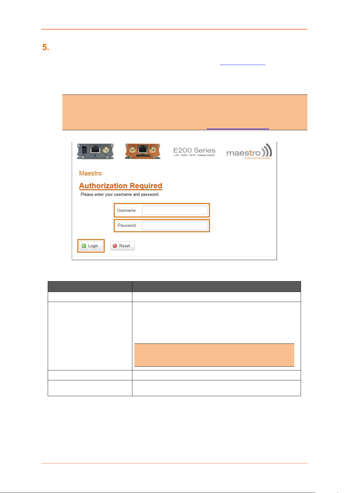
Logon Procedure
Open a Web browser on the computer, and enter the LAN IP Address http://192.168.1.1 of the Lantronix
Router in browser’s URL box. A dialog box appears prompting the user to enter Username and
Password.
Note
• The default LAN IP Address of Lantronix Router is 192.168.1.1.
• DHCP must be enabled on the computer to access Lantronix Router with LAN IP
Address 192.168.1.1. For more information refer How to Enable DHCP?
Screen 5-1: Login Page
Parameters Description
Username Enter the Username admin.
Password Enter the Password.
If you are logging on for the first time after the installation, please
use the default password admin.
Note
• We strongly recommend you to change your login
password.
Login Button Logs on to Router’s GUI. Click Login Button.
Reset Button Click Reset Button to discard the provided password and re-type
the Username and Password.
Table 3.3-1: Login Page
E220 Series Cellular Router User Guide 14
Page 15

Common Icons and Buttons
Common Icons and Buttons
• Save – Saves the new/modified configuration.
Note
• All saved configuration will be lost on Router reboot, if they are not saved and
applied.
• Save & Apply – Saves the new/modified configuration and loading the
configuration into the Router.
• Reset – Discards the unsaved configuration. This allows the user to provide the
configuration details again on the GUI page.
• Add – Add a field.
• Delete – Delete a field.
• Reveal/Hide Passw ord – Click to reveal and verify th e pass word. C lick it again t o hide th e
password and secure it.
E220 Series Cellular Router User Guide 15
Page 16
Quick Setup
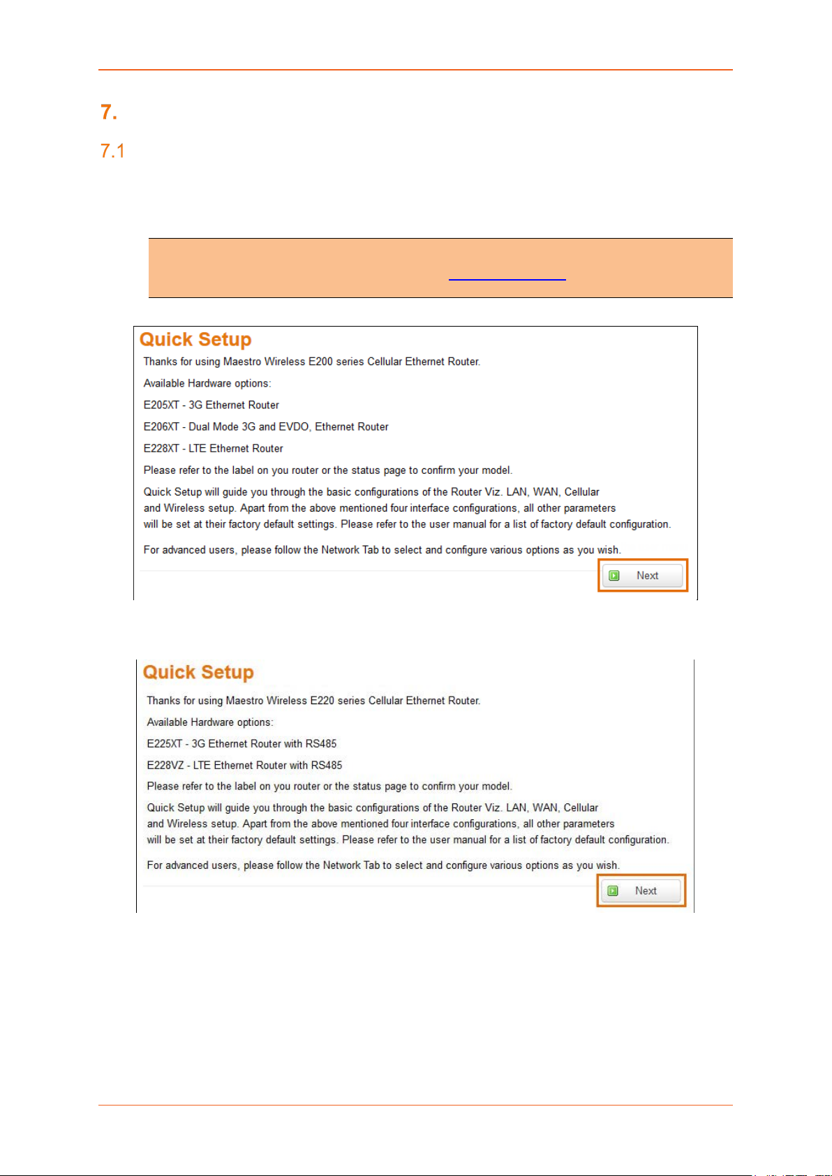
Quick Setup
Quick Setup
Quick Setup > Quick Setup
Quick Setup page will guide the administrator through the steps required to configure the basic
parameters needed for the router to come up and start running.
Note
• Alternately, an administrator can go to Network Settings and import and load a
predefined settings file.
Screen 7-1a: E200 Router Information
Screen 7-2b: E200 Router Information
E220 Series Cellular Router User Guide 16
Page 17
Quick Setup
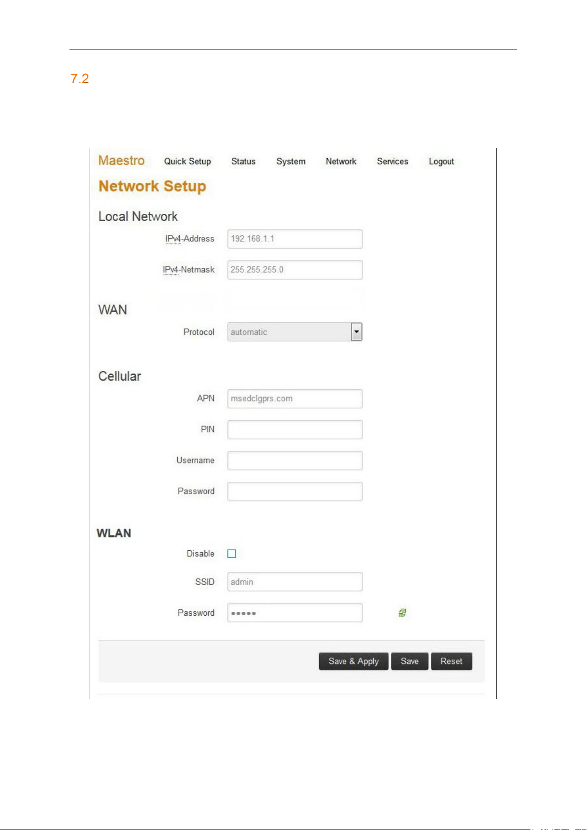
Network Setup
Quick Setup > Quick Setup > Network Setup
Basic network parameters for LAN, WAN, Cellular and Wi-Fi can be configured from the Network Setup
page.
Screen 7-2: Quick Start Network Configuration
E220 Series Cellular Router User Guide 17
Page 18

Quick Setup
Parameters Description
Local Network
IPv4-Address Enter an IPv4 Address for the LAN interface. This is the IP Address
that must be used to access the Router.
The default LAN IPv4 Address is 192.168.1.1.
Ipv4-Netmask Enter IPv4 Subnet Mask of the LAN interface.
The default Netmask is 255.255.255.0
WAN
Protocol Select the WAN protocol from the available options:
Available Options
• Manual
• Automatic
• PPPoE (Point to Point Protocol over Ethernet)
The default WAN protocol is selected as Automati c.
Cellular
APN Access Point Name (APN) is the name of an access point for the
cellular network data con nect i on. Gener ally , the wireless cellular
network operator will provide the APN to their end users.
Enter the APN provided by the cellular network operator.
PIN SIM card Personal Identification Number (PIN) is used to lock the
card, preventing people from making unauthorized phone call or
accessing cellular data services.
Enter the PIN of the SIM card.
Username Enter the login name.
The default Username for Lantronix E200 Router is admin.
The default Username for Lantronix E220 Router is Maestro E220.
Password Enter the password.
WLAN
Disable By default, Wi-Fi interface is in enable mode. Check to disable the
Wi-Fi interfac e if you do not want to use it.
SSID Service Set Identifier (SSID) is a sequence of characters which
uniquely names a wireless local area network (WLAN).
The default SSID is Maestro E200.
Password The default password is W1rele$$.
Table 7.2-1: Quick Start Network Configuration
E220 Series Cellular Router User Guide 18
Page 19

Status
Status
Status provides a s ummary view a ll the vital config urations of your Lantronix Router such as routing
information, firewall details, traffic statistics including real-time graphs.
• Overview
• Firewall
• Routes
• System Logs
• Real-Time Graphs
Overview
Status > Overview
Overview page provides a quick and bird-eye overview of all the important parameters of your Lantronix
router that requires special attention.
Status
Status > Overview > Status
Status Overview page outlines the setting details of basic sub-modules that must be configured for the
Router. Status Overview uses tables to display information. The Status page provides information
about:
• System
• Cellular
• Memory
• Network
• MWAN Interface Live Status
• DHCP Leases
• DHCPv6 Leases
• Wireless
• Associated Stations
E220 Series Cellular Router User Guide 19
Page 20
Status
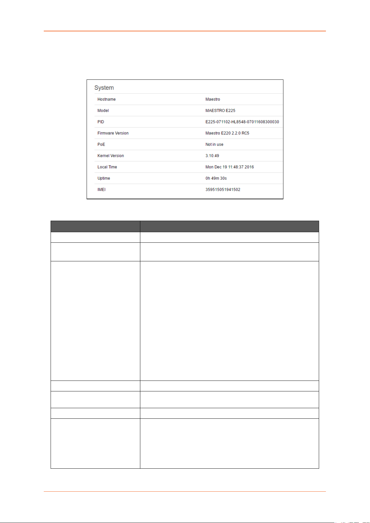
A. System
Status > Overview > Status
The System group provides the Router make and software related information.
Screen 8-1A System Status Overview
Parameters Description
Hostname Name assigned to the router for addressing purposes.
Model Model number of the router that is deployed.
Example – Lantronix E225
PID Display 35 characters long, unique Product Identification number
(PID).
Consider an example of PID E225-071102-HL8548-xxxxxxxxxxxxxx.
It is composed of:
• 4 characters SKU: E225
• 6 characters UID: 071102 (WAN, GNSS, Wi-Fi, 2x LAN,
SIM)
• 6 character Module Name: HL8548
• 14 characters Serial Number:
• xxxxxxxxxxxxxx. Comprises of HW/PCB version (01 to 99),
Lot number (01 to 99), Production date (YYMMDD), Unit
number (4 digits).
•
Firmware Version Base Firmware Version number.
POE Power Over Ethernet is available in E220 series where the Router
can be powered from a PSE-POE device over WAN port
Kernel Version The Linux Kernel version number on the router.
Local Time Displays the day of the week, month, date, time and year configured
on the router.
The format is Day Month Date hh:mm:ss Year.
The time is displayed in 24 hour clock format.
E220 Series Cellular Router User Guide 20
Page 21

Status
Parameters Description
Up Time Displays the time for which the router is up and running since last
power ON.
The format is hh:mm:ss.
The time is displayed in 24 hour clock format.
Last Reboot Cause Displays the last reboot event time and cause for the Router
IMEI/MEID
(MEID is only available in
CDMA / EVDO Routers)
Displays 15 digit IMEI number or 14 digit MEID number.
An IMEI number (International Mobile Equipment Identity) is a 15 or
17 digit unique numbers to identify GSM or UMTS mobile devices. It
is used to prevent call initiation from a misplaced or stolen GSM or
UTMS device, even if someone swaps out the device’s SIM card.
A MEID number (Mobile Equip ment I den tifi er ) is used to identify a
cell phone that utilizes the CDMA technology for wireless service.
Note
• We recommend you record the IMEI or MEID number and
secure it, so that it can be quickly accessed in the event of
theft or loss of the router.
Table 8.1-A: System Status Overview
E220 Series Cellular Router User Guide 21
Page 22
Status
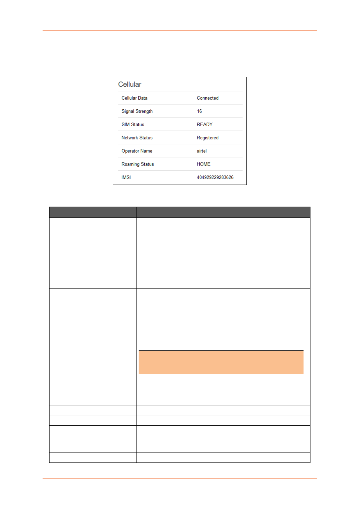
B. Cellular
Status > Overview > Status
The Cellular group provides the status of the SIM card inserted in the router.
Screen 8-1B: Cellular Status Overview
Parameters Description
Cellular Data Displays the status of the Cellular data.
Status
• ERROR – SIM Card is not available in the Router or
cellular connectivity malfunction.
• Connected – SIM card is active, and is connected f or data
communication.
• Disconnected – SIM card is inactive and there is no data
communication.
Signal Strength Displays the current signal strength.
The signal strength range is 0 to 32.
• 0 –113 dBm or less
• 1 –111 dBm
• 2 to 30 –109 to –53 dBm
• 31 – 51dBm or greater
Note
• Signal strength for a good cellular data connection must be
12 or above.
SIM Status Displays the availability of SIM card in SIM card slot.
• Error – SIM card is not inserted.
• Ready – SIM card is inserted.
Network Status The registration status of the router on the current cellular network.
Operator Name Name of the current cellular operator in use.
Roaming Status The roaming status of the router:
• Home
• Roaming
IMSI Displays the IMSI Number. In case of UMTS, it is read from the SIM
E220 Series Cellular Router User Guide 22
Page 23

Status
card.
Parameters Description
An International Subscriber Identity (IMSI) is 15 digit unique Mobile
number associated with cellular network and used to acquire the
details of the mobile for identifying the user of a cellular network.
ESN (Only for CDMA / EVDO
Routers)
Revision (Only for CDMA /
EVDO Routers)
Cellular Module Info (Only for
E206)
Displays the ESN number of cellular module. It must be sub s cribe d
for a Verizon account (EVDO).
Displays the Firmware revision number of the cellular module.
Displays the critical parameters from the cellular module.
Table 8.1-B: Cellular Status Overview
E220 Series Cellular Router User Guide 23
Page 24
Status
E205XT02
E206XT
32MB
32MB
E220LITE
64MB
32MB
E210
128MB
32MB
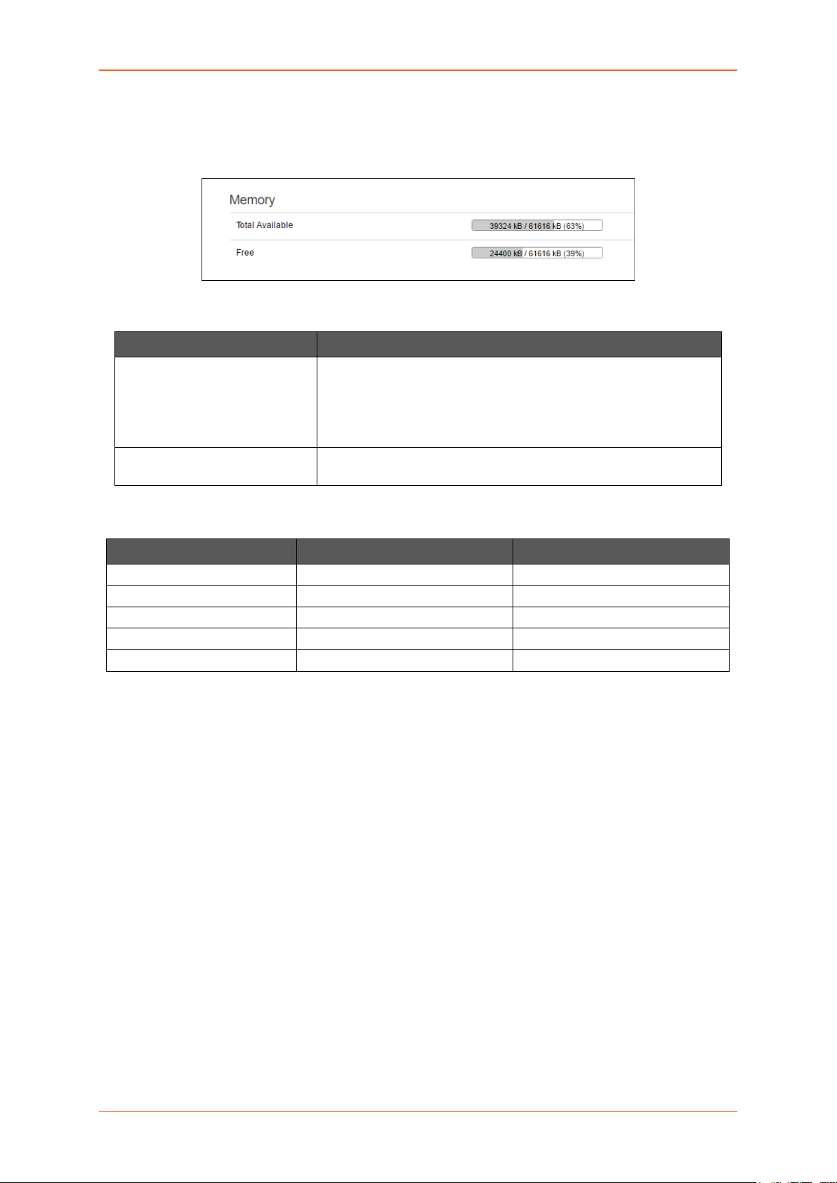
C. Memory
Status > Overview > Status
The Memory group provides information about the Memory in KB available with the router.
Screen 8.1-C: Memory Status Overview
Parameters Description
Total Available Total available RAM memory. Total Memory is summation of used
memory, free memory, buffered memory and cached memory.
Grey highlight and the percentage valu e disp lay the amount of used
memory.
Free Free RAM memory. Grey highlight and the percentage value display
the amount of used memory.
Table 8.1-C1: Memory Status Overview
Model RAM size Flash size
32MB 32MB
E220 128MB 64MB
Table 8.1-C2: Memory Status Overview
E220 Series Cellular Router User Guide 24
Page 25
Status
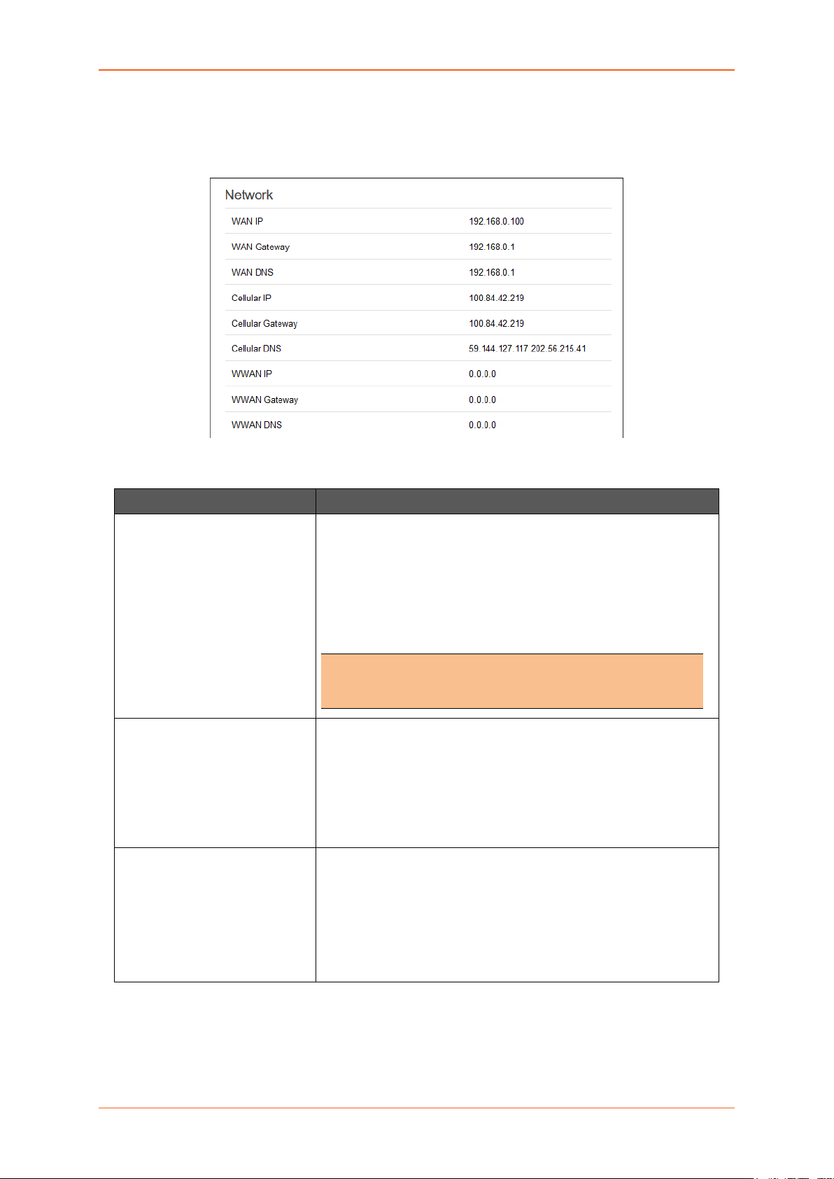
D. Network
Status > Overview > Status
The Network group provides the status of IPv4and IPv6 WAN status
Screen 8-1D: Network Status Overview
Parameters Description
WAN Displays status of fixed-line WAN connection with following details:
• IP – IP Address of the WAN Interface.
• Gateway – IP Address of the WAN Interface Gateway.
• DNS – Two DNS IP Add ress; Primary DNS Server and
Secondary DNS Server.
Note
• In case of WAN Access Wi-Fi must be configured in client
mode and connected to an Access Point.
Cellular Displays status of Cellular network data connection with following
details:
• IP – IP Address of the Cellular Interface.
• Gateway – IP Address of the Cellular Interface Gateway.
• DNS – Two DNS IP Address; Primary DNS Server and
Secondary DNS Server.
WWAN Displays status of Wi-Fi WWAN connection with following details:
• IP – IP Address of the WWAN Interface.
• Gateway – IP Address of the WWAN Interface Gatew ay .
• DNS – Two DNS IP Address; Primary DNS Server and
Secondary DNS Server.
Table 8.1-D: Network Status Overview
E220 Series Cellular Router User Guide 25
Page 26
Status
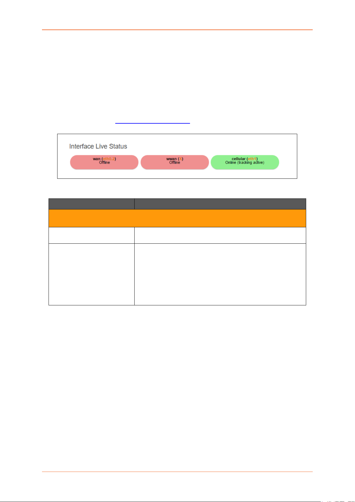
E. MWAN Interface Live Status
Status > Overview > Status
Lantronix routers E200 and E220 series ha ve multiple s ources of Internet and can switch s eamlessl y
between them. T he below screenshot shows 3 sources of Internet which is WAN (Wired Ethern et),
WWAN (Wi-Fi when used as a WAN instead of LAN which is the default conf ig ur a tion) and Ce llu lar.
MWAN Interface provides a birds-eye view of all the avail able and connected WAN options. In the
example figure below, the interfaces marked in Green are live and connected while the ones in red are
currently offline.
For more information, refer Network > Load Balancing
Screen 8-1E: MWAN Interface Live Status
Parameters Description
.
Multiple WAN Interface Live Status
Indicates the current status of the interferes – WAN, WWAN, 3G
Offline The interfaces that are not connected to network are marked in
RED.
Online The interfaces that are connected to the network are marked in
GREEN.
Status
• Tracking off – The interface will not track the availability
of the other active interface.
• Tracking active – The inte rface will trac k the availabi lity
of the other active interface.
Table 8.1-E: MWAN Interface Live Status
E220 Series Cellular Router User Guide 26
Page 27
Status
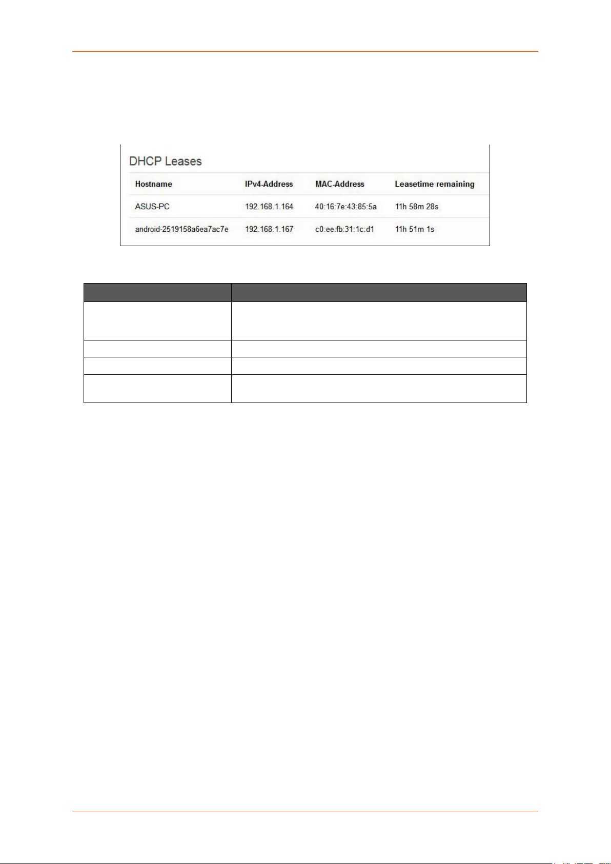
F. DHCP Leases
Status > Overview > Status
Displays the inform ation about the machines conn ected to router using a DHCP l ease. This incl udes
IPv4 as well as IPv6 connections.
Screen 8-1F: DHCP Lease Status Overview
Parameters Description
Host Name Name of the device (laptop, mobile, etc.) that is connected to the
router and has been leased an IPv4 Address by the router’s DHCP
server.
IPv4 Address IPv4 Address assigned to the device connected to the router.
MAC Addr e s s MAC address of the device connected to the router.
Leasetime remaining The remaining time for which the device can use the DHCP server
leased IPv4 Address.
Table 8.1-F: DHCP Lease Status Overview
E220 Series Cellular Router User Guide 27
Page 28
Status
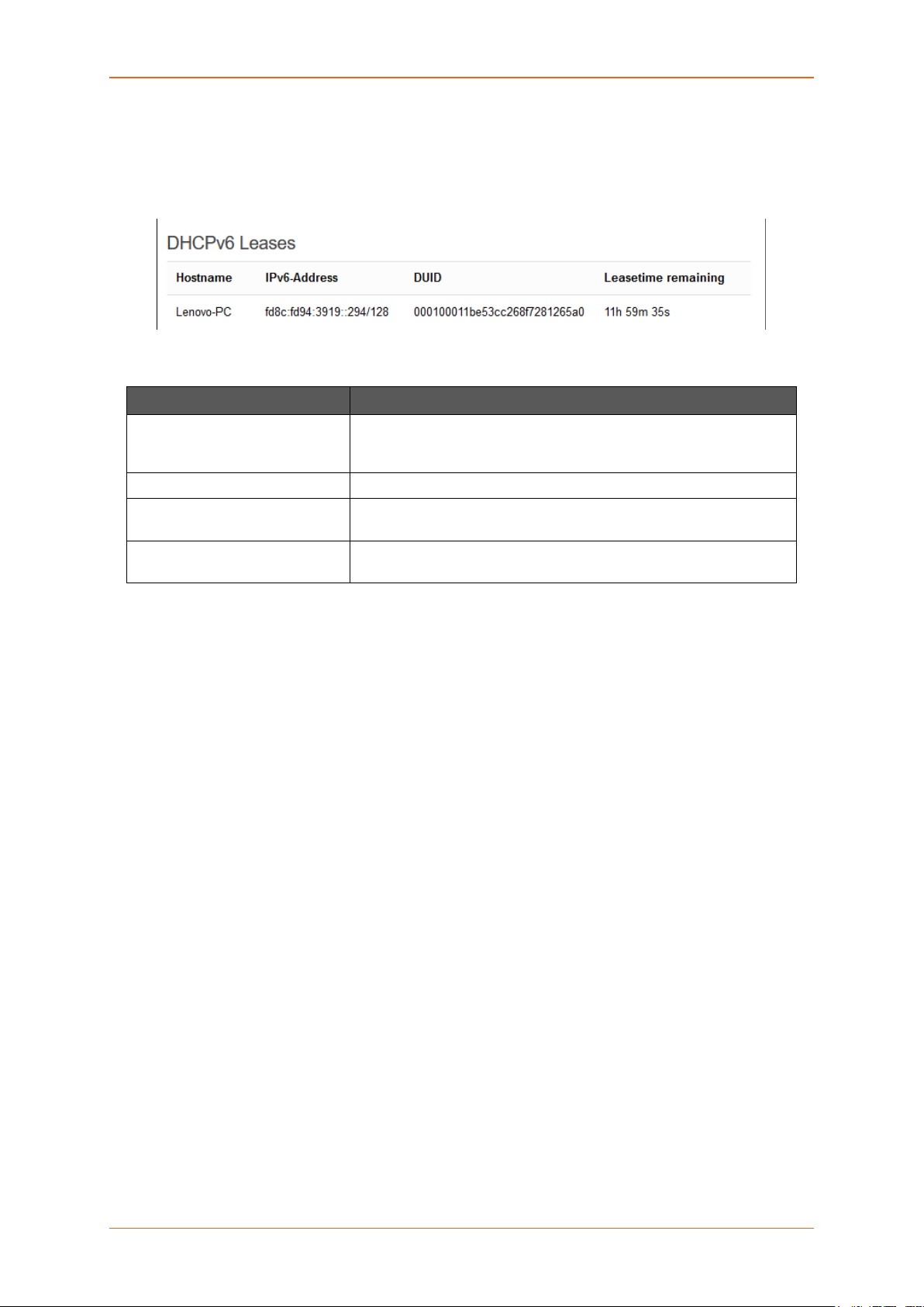
G. DHCPv6 Leases
Status > Overview > Status
Displays the inform ation about t he mac hines connected t o router us ing DHCPv 6 lease. This includes
IPv4 as well as IPv6 connections.
Screen 8-1G: DHCPv6 Lease Status Overview
Parameters Description
Host Name Name of the device (laptop, mobile, etc.) that is connected to the
router and has been leased an IPv6 Address by the router’s
DHCPv6 server.
IPv6 Address IPv6 Address assigned to the device connected to the router.
DUID DUID (Device Unique Identifier) of the device connected to the
router
Leasetime remaining The remaining time for which the device can use the DHCPv6 sever
leased IPv6 Address.
Table 8.1-G:DHCPv6 Lease Status Overview
E220 Series Cellular Router User Guide 28
Page 29

Status
H. Wireless
Status > Overview > Status
The Wireless Group provides the detail information of the Wi-Fi network used by the router.
Screen 8-1H: Wireless Status Overview
Parameters Description
Connection Name Displays the name of the connection and the details:
SSID – A Service Set Identifier (SSID) is a public identifier of 32
characters that uniquely names a Wireless Local Area Network
(WLAN)
Mode – Displays whether the WLAN interface is currently configured
as an Acce ss Point ‘Master’ or as a Client of a higher order Wi-Fi
network.
Note
• For Wi-Fi WAN operation this should be ‘Client’.
• Channel – Wireless Local Area Network channel.
• Bitrate – Data transfer rate
• BSSID – Displays Basic Service Set Identification
(BSSID); 24 bit MAC Address of Wireless device.
• Encryption – Displays the data encryption method.
• Signal Strength – Displays the signal strength in
percentage.
Table 8.1-H: Wireless Status Overview
E220 Series Cellular Router User Guide 29
Page 30
Status
I. Associated Stations
Status > Overview > Status
The Associated Stations gr oup enlists the com puters and/or devices that are connected to the ro uter
over Wi-Fi.
Note
• Associated Station details are available only when router is configured as Master
(access point).
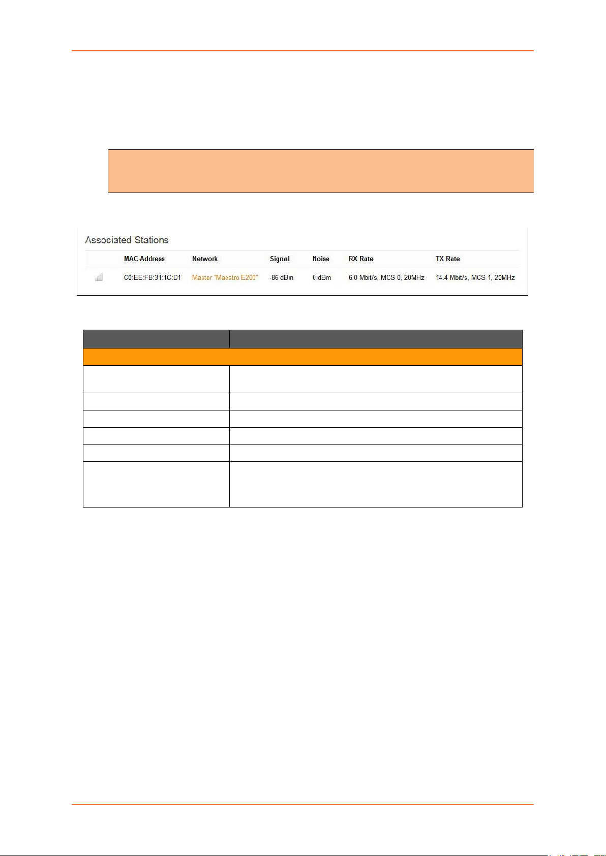
Screen 8-1I: Associated Stations Status Overview
Parameters Description
Associated Stations
MAC Addr e s s MAC Address of the computers and/or devices that are connected to
the router.
Network Mode and Name of the network to which the device is connected.
Signal Signal strength in dBm
Noise Noise in dBm
RX Rate Data transfer rate at which the data is received.
TX Rate Data transfer rate at which the data is transmitted.
• Modulation and Coding Scheme (MCS) 1,
• High Throughput (HT) 20 Mhz
Table 8.1-I: Associated Stations Status Overview
E220 Series Cellular Router User Guide 30
Page 31

Status
Firewall
Status > Firewall
IPv4 Firewall
Status > Firewall > IPv4 Firewall
Screen 8.2.1: IPv4 Firewall Status
E220 Series Cellular Router User Guide 31
Page 32

Status
Parameters Description
Reset Counters Click to rest counters Packets and Traffic.
Reset Firewall Click to reload the existing Firewall configuration of every interface.
Rule # Displays the serial number of Firewall Rule.
Pkts Displays the number of accepted packets.
Traffic Displays the amount of traffic captured by the filter.
Target Displays the target action for the traffic processed for a respective
rule.
Prot. Displays the name of all the protocols configured in the Firewall
Rule.
In Input Interface
Out Output Interface
Source Displays the source IPv4 Address.
Destination Displays the destination IPv4 Address.
Table 8.2-1: IPv4 Firewall Status
E220 Series Cellular Router User Guide 32
Page 33

Status
IPv6 Firewall
Status > Firewall > IPv6 Firewall
Screen 8.2.2 IPv6 Firewall Status
Parameters Description
Reset Counters Click to rest counters Packets and Traffic.
Reset Firewall Click to reload the existing Firewall configuration of every interface.
Rule # Displays the serial number of Firewall Rule.
Pkts Displays the number of accepted packets.
Traffic Displays the amount of traffic captured by the filter.
Target Displays the target.
Prot. Displays the name of all the protocols configured in the Firewall
Rule.
In Input Interface
Out Output Interface
Source Displays the source IPv6 Address.
E220 Series Cellular Router User Guide 33
Page 34

Status
Parameters Description
Destination Displays the destination IPv6 Address.
Options Displays the destination IPv4 Address.
Table 8.2-2: IPv6 Firewall Status
E220 Series Cellular Router User Guide 34
Page 35

Status
Routes
Status > Routes
Screen 8-3: Routes Status
Parameters Description
ARP – ARP table provides information about the peripherals connected on each interface
IPv4 Address Displays the IPv4 Address.
MAC Address Displays MAC Address of the peripheral device.
Interface Displays the interface name connected to the peripheral device.
Active IPv4 Routes – Displays the active IPv4 network route information.
Network Displays the network Type used by the active IPv4 routes.
Target Displays the destination IPv4 Address.
IPv4 Gateway Displays the IPv4 Address Gateway used for traffic routing.
Metric Displays the metric assigned to the Interface.
E220 Series Cellular Router User Guide 35
Page 36

Status
Active IPv6 Routes – Displays the active IPv6 network route information.
Network Displays the network Type used by the active IPv4 routes.
Target Displays the destination IPv6 Address.
IPv6 Gateway Displays the IPv6 Address Gateway used for traffic routing.
Metric Displays the metric assigned to Interface.
Table 8.3-1: Routes Status
E220 Series Cellular Router User Guide 36
Page 37

Status
System Logs
Status > System Logs
The E2xx series router provides extensive logging capabilities for traffic, system and network protection
functions. Detailed log inform ation and r ep orts pr ov ide his toric a l as well as current anal ysis of net work
activity to help identify security issues and reduce network abuse.
The E2xx series router can either store logs local ly or send lo gs to ex ternal s yslo g servers for storage
and archival purposes.
The E2xx series router can log many different network activities and traffic including:
• Firewall logs
• Interface Activity logs
• Administrator logs
• User Authentication logs
The E2xx series router supports a single s yslog servers for remote logg ing and it can be configured
from System > System > Logging
The E2xx series router can either store logs locally or send to the Syslog UDP servers.
.
Screen 8-2: System Logs
E220 Series Cellular Router User Guide 37
Page 38

Status
Realtime Graphs
Status > Realtime Graphs
Use Real-Time Graph to view Router related activities for different time intervals.
The period wise graph will display the following graphs for the selected period: Load Average, Interface
Traffic inform ation (LAN, WAN, Tunnel, Wi-Fi), Wireless usage Information and Conn ection detailed
information.
Wireless
Status > Realtime Graphs > Wireless
Wireless indicates t he traffic on Wi-Fi irres pective of Wi-Fi being used as an access point (LAN) or
Client (WAN).
Wireless Graphs disp lays real time graph combined for Signa l and N o ise d ata transferred in real time.
Colors differentiate Signal and Noise data rat es. It also displays the Physical data transfer rate. In
addition, shows the average and peak Signal and Noise and Physical data rates individually.
Screen 8-3: Real Time Wireless Traffic Graph
Parameters Description
WLAN Interface
Signal Graph shows the periodic average of Signal and Noise on the
Router.
E220 Series Cellular Router User Guide 38
Page 39

Status
Parameters Description
Details
• X axis – Time Interval (1 minute)
• Y axis – Data Rate (Mbit/s)
Legends
• Blue – Signal
• Red – Noise
• Green – Physical Rate
Table 8.5-1: Real Time Wireless Traffic Graph
E220 Series Cellular Router User Guide 39
Page 40

Status
Load
Status Realtime Graphs > Load
Graph shows past three minutes average CPU load and peak CPU load on the router.
Screen 8-4: Real Time Load Graph
Parameters Description
Load Graph shows the periodic average CPU load on the Router.
Details
• X axis – Time Interval (1 minute)
• Y axis – CPU Load (Percentage)
Legends
• Red – 1 Minute Load
• Orange – 5 Minute Load
• Yellow – 15 Minute Load
Table 8.5-2: Real Time Load Graph
E220 Series Cellular Router User Guide 40
Page 41

Status
Traffic
Status > Realtime Graphs > Traffic
Traffic indicates the WAN side inc oming an d outgoin g traf fic. Traff ic Graphs displ ays com bined graph
of Upload and Download data transfer. Colors differentiate upload and download data traffic. In addition,
shows the average and peak data transfer for upload and download individually.
A. LAN
Graph shows past three minutes average LAN traffic and peak LAN traffic on the router.
Screen 8-5: Real Time LAN Traffic Graph
Parameters Description
Traffic (Inbound / Outbound) Graph shows the periodic average LAN Traffic on the Router.
Details
• X axis – Time Interval (1 minute)
• Y axis – LAN Traffic (kB/s)
Legends
• Blue – Inbound Traffic
• Green – Outbound Traffic
Table 8.5-3: Real Time LAN Traffic Graph
E220 Series Cellular Router User Guide 41
Page 42

Status
B. WAN
Graph shows past t hree minutes average W AN and Cellul ar traff ic and peak WAN and Ce llular tr affic
on the router.
Screen 8-6: Real Time WAN Traffic Graph
Parameters Description
Traffic (Inbound / Outbound) Graph shows the periodic average WAN and Cellular Traffic on the
Router.
Details
• X axis – Time Interval (1 minute)
• Y axis – WAN and Cellular Traffic (kB/s)
Legends
• Blue – Inbound Traffic
• Green – Outbound Traffic
Table 8.5-4: Real Time WAN Traffic Graph
E220 Series Cellular Router User Guide 42
Page 43

Status
C. Cellular
Graph shows past two minutes average Cellular traffic and peak Cellular traffic on the router.
Screen 8-7: Real Time Cellular Traffic Graph
Parameters Description
Traffic (Inbound / Outbound) Graph shows the periodic average Cellular Traffic on the Ro u ter.
Details
• X axis – Time Interval (1 minute)
• Y axis – Tunnel Traffic (kB/s)
Legends
• Blue – Inbound Traffic
• Green – Outbound Traffic
Table 8.5-5: Real Time Cellular Traffic Graph
E220 Series Cellular Router User Guide 43
Page 44

Status
D. Tunnel
Graph shows past three minutes average Tunnel traffic and peak Tunnel traffic on the router.
Screen 8-8: Real Time Tunnel Traffic Graph
Parameters Description
Traffic (Inbound / Outbound) Graph shows the periodic average Tunnel Traffic on the Rout er.
Details
• X axis – Time Interval (1 minute)
• Y axis – Tunnel Traffic (kB/s)
Legends
• Blue – Inbound Traffic
• Green – Outbound Traffic
Table 8.5-6: Real Time Tunnel Traffic Graph
E220 Series Cellular Router User Guide 44
Page 45

Status
E. Wi-Fi
Graph shows past three minutes average Wi-Fi traffic and peak Wi-Fi traffic on the router.
Screen 8-9: Real Time Wi-Fi Traffic Graph
Parameters Description
Traffic (Inbound / Outbound) Graph shows the periodic average Wi-Fi Traffic on the Router.
Details
• X axis – Time Interval (1 minute)
• Y axis – Wi-Fi Traffic (kB/s)
Legends
• Blue – Inbound Traffic
• Green – Outbound Traffic
Table 8.5-7: Real Time Wi-Fi Traffic Graph
E220 Series Cellular Router User Guide 45
Page 46

Status
Connection
Status > Realtime Graphs > Connection
Connection graphs provides an overview of active network connections; those originating from the
Router and also those that are originating from LAN/WAN of the Router.
Screen 8-10: Real Time Connection Traffic Graph
Parameters Description
Protocol Graph shows the periodic average of data transfer using specific
protocols on the Router using the active connections in real time.
Details
• X axis – Time Interval (1 minute)
• Y axis – Number of Active Connections
Legends
• Blue – UDP
• Green – TCP
• Red – Other Protocols
Network Network connection type, IPv4 or IPv6.
Protocol Name of the prot oco l used for routing data.
Source Source IP Address and port number of an active connection.
Destination Destination IP Address and port number of an active connection.
E220 Series Cellular Router User Guide 46
Page 47

Status
Parameters Description
Transfer Displays the total data transferred using the specific network
connection.
Table 8.5-8: Real Time Connection Traffic Graph
E220 Series Cellular Router User Guide 47
Page 48

System
System
System allows conf iguration and administrati on of rout er for secure local and rem ote managem ent. It
also provides the basic system settings, time management, language settings, Software packages
updates, firmware updates and reboot schedules of the Router.
• System
• Administration
• Software
• Backup / Flash Firmware
• Reboot
Systems
System > System
General Settings
System > System > General Settings
The current date and time of the router’s internal clock can be set locally to match the date/time of your
computer’s browser or the router can be configured to synchronize its internal clock with an NTP server
so that logs show the precise time and router activities can also happen at a precise time.
Screen 9-1: System General Settings
E220 Series Cellular Router User Guide 48
Page 49

System
Parameters Description
Local Time Current router time.
Click “Sync with browser” button to synchronize router clock wit h the
local computer browser.
Note
• The displayed time is dependent on the configuration of
your local computer that is being used as NTP server.
Hostname Enter the Hostname. The configured Hostname appears on the
Status > Overview page
Timezone Select time zone according to the geographical region in which
Router is deployed.
Time Synchronization
GPS Time sync For The E2xx series router models which support GPS functionality,
you can sync the time with GPS.
Note
• GPS Antenna will be needed for GPS time sync
.
NTP time sync Enable if you want Router to get time from an NTP server.
Note
• If NTP Server is activated, the Router will update time every
60 minutes from the NTP Servers.
• Enabling NTP Client consumes data.
Provide NTP Server Click to use the router as a NTP server and port details
Table 9.1-1: System General Settings
E220 Series Cellular Router User Guide 49
Page 50

System
Logging
System > System > Logging
The Router can capture and log system activity including interface connection status, internal debugging
messages, critical and emergency logs. It can either store the logs locally and/or send them to external
UDP syslog server for storage and archival purposes . The system log buffer uses First In First Out
(FIFO) mechanism.
Note
• All the logs are lost on Router reboot.
SYSLOG is an industry standard protocol/method for collecting and forwarding messages from devices
to a server running a syslog daemon usually via UDP Port 514. The syslog server on a remote computer
accepts the log m essages and stor es them in fi les or prints them. Logging to a central s yslog server
facility helps in the aggregation of associated logs and alerts and provides protected long term storage.
This is useful for incident handling, routine troubleshooting and historical analysis.
Screen 9-2: Syslog Configurations
Parameters Description
System log buffer size Enter the size of the buffer in Kilobytes (KB) to save logs and stus
information details.
The default System Log Buffer size is 16 KB.
External system log UDP
server
External system log UDP Enter the Port number of an External UDP server system.
Enter the IP Address of an External UDP server system. This server
will be used to save all the real time logs.
The default IP Address of external log server is 0.0.0.0
Note
• Enabling Remote Log features requires a Router to be
manually rebooted in all firmware versions below V2.2.0
E220 Series Cellular Router User Guide 50
Page 51

System
server port
UDP server is used to store the system logs
Parameters Description
The default Port number of external log server is 514.
Log output level Select the Log output level to serve for one of the following purpose:
• Debug – Logs will be used by The E2xx series router
software developer for debugging the router application.
These logs are not useful during operations.
• Info – These logs provide normal operational information
messages that are used for general purposes like
reporting.
• Notice – Provides alerts for peculiar events that a re not an
error. These logs help to identify potential issues. Since
these logs do not indicate errors, immediate action
may/may not be necessary.
• Warning – A warning messages is displayed for a
potential issue, indicating to take an action. An error may
occur if no action is taken against the warning issued.
• Error – Displa y s the logs indicating an error condition.
Note
For help with log errors, please contact Lantronix Technical
Support.
• Critical – Indicates failure in secondary system and must
be corrected immediately.
• Alert – Problems which should be corrected immediately.
• Emergency – System is Unusable.
Cron log level Select the criticality level of output.
• Debug – Helps you debug cron process whi ch has f ailed
during runtime.
• Normal – Normal informational messages
• Warning – Indicates some issues can happen or error
could be generated in cron process.
Note
• For help with Cron log warning messages, please contact
Lantronix Technical Support.
Table 9.1-2: Syslog Configurations
E220 Series Cellular Router User Guide 51
Page 52

System
Language and Style
System > System > Language and Style
Screen 9-3: Language and Style Configurations
Parameters Description
Language Select preferred language as English.
Default value is auto.
Design Select Bootstrap design of the user interface.
Default design selected is bootstrap.
Table 9.1-3: Language and Style Configurations
E220 Series Cellular Router User Guide 52
Page 53
System
Administration
System > Administration
The Administration page allows configuration of the general settings in Router. Various ports and login
security can be configured using Administration submenu.
Router Password
System > Administration > Router Password
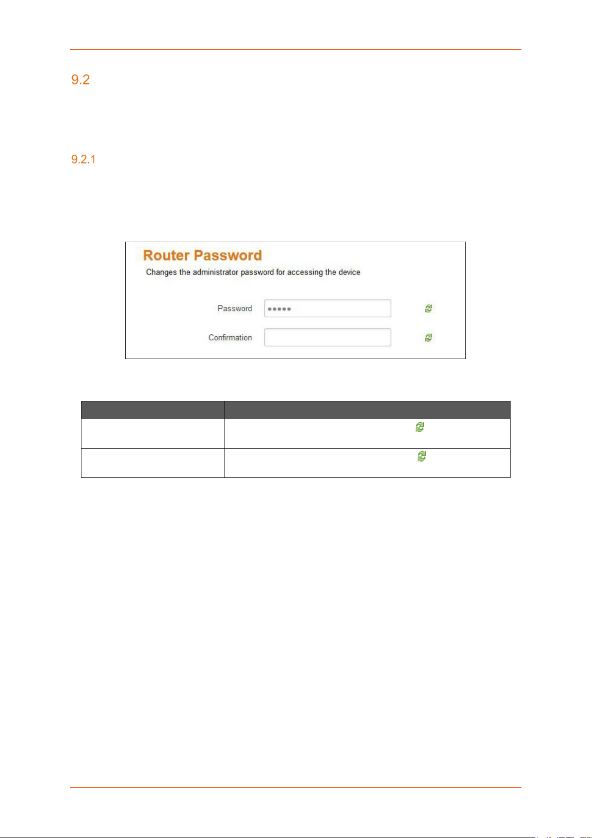
The Router is shipped with the default – username & password credentials set as “admin”. This
administrator is alwa ys authentic ated locall y i.e. b y Router itself . We rec ommend that you change the
password for this username immediately after deployment.
Screen 9-4: Router Credential Configurations
Parameters Description
Password
Confirmation
Specify the new administrator password. Click to reset the
password and re-type.
Confirm the new administrator password. Click to reset the
password and re-type.
Table 9.2-1: Router Credential Configurations
E220 Series Cellular Router User Guide 53
Page 54

System
SSH Access
System > Administration > SSH Access
The E series integrate Dropbear which offers SSH network shell access and an integrated SCP (Secure
Copy Protocol) server.
You can also set param eters for Dr opbear Instance for SSH Access and you ca n paste public SSH Keys (one per line) for SSH public-key authentication.
By default the remote S SH ac c ess over WAN is disabled. You can enable the r e mote SH access from
Web Interface or alternate ly can send an SMS fr om a registered adm in number to enable it. You are
required to use the SSH keys
displayed on the webpage for SSH access.
Screen 9-5: SSH Access Configurations
E220 Series Cellular Router User Guide 54
Page 55

System
Parameters Description
Dropbear Instance
Interface Select the interface. SSH listens only on the selected interface.
Note
• Interface options celldhcp and cellular is available only in
E206.
If unspecified option is selected it listens to all the interfaces.
Port Provide listening port of the Dropbear instance.
Default port is 22.
Password Authentication Select to allow authentication using SSH password. By default it is
disabled.
Gateway ports Select to allow remote hosts to connect to local SSH forwarded
ports.
Add Click Add button to add an Interface.
Delete Click Delete button to delete the Interface
SSH Keys
Public SSH keys can be provided one per line for authenticating with SSH public-key.
Note
• Public SSH keys are provided by default. They are configured by default on Port 22. SSH are by
default disabled WAN access. You can either enable Port 22 from the Web inte rface or usi ng the
SMS.
Table 9.2-2: SSH Access Configurations
E220 Series Cellular Router User Guide 55
Page 56

System
Software
System > Software
Software page give you access to the list of install ed as well as available softw are package or filter
installed on your router. In addition, E Series router allows the user to install their developed application
rd
packages and 3
packages, please contact Lantronix Technical Support
Lantronix has its own list of packages which would be downloaded from D2Sphere. For details on
D2Sphere, please contact your regional Lantronix Sales office
Actions
System > Software > Actions
A. Installed
party packages. For inform ation about installing your own or third-party application
.
.
Screen 9-6: Software Installation and Installed Package Details
Parameters Description
Update lists Click to update the package li s t from the packag e repos itor y serv ers.
Free space Indicates the free space and used space on flash memory.
Legends
E220 Series Cellular Router User Guide 56
Page 57

System
• Red – Used space
Parameters Description
• Green – Free space
Download and install
package
Filter Enter the keyword of the required package and click Find Package
Find package Click Find package button to search the package.
Status – Installed Package
Package name Displays the name of installed package.
Version Displays the version of installed package.
Table 9.3-1: Software Installation and Installed Package Details
Enter the exact name of the package to be downloaded from
package repository servers and install it. Click OK initialize
installation.
to search it from package repository servers.
E220 Series Cellular Router User Guide 57
Page 58

System
B. Available Packages
Screen 9-7: Software Packages Available for Installation
Parameters Description
Install Click Install against respective Package to install it.
Package name Displays the name of package.
Version Displays the version of package.
Description Displays the description of package.
Table 9.3-2: Software Packages Available for Installation
E220 Series Cellular Router User Guide 58
Page 59

System
Configuration
System > Software > Configuration
This configuration page provides the path to the router as to where it should go and update the
packages. All Lantronix packages would be updated f rom D2Sphere.com however you can add your
own http servers where you wish to upload your packages.
Screen 9-8: Software Configuration - OPKG
E220 Series Cellular Router User Guide 59
Page 60

System
Backup / Flash Firmware
System > Backup / Flash Firmware
Backups are required in order to keep the working configuration data. This backup file can also be used
to configure other Routers for same settings, instead of configuring each of them for every parameter.
Backup consists of all the policies and all other user related information. Once the backup is taken, you
need to upload the file for restoring the backup.
Note
• Restoring older configuration leads to the loss of current configuration.
Flash Operation
System > Backup / Flash Firmware > Flash Operation
A. Actions
Screen 9-9: Backup - Restore and Flash Operations
Parameters Description
Backup/Restore
Download Backup Click Generate archive button to download a .tar archive file of the
current configuration files.
Reset to defaults Click Factory Reset button to reset the firmware to its default
E220 Series Cellular Router User Guide 60
Page 61

System
configurations.
Parameters Description
Note
• This valid only with squashfs images.
Restore backup Click browse to select the configuration file to restore backup.
OR
Click “Upload archive” button to upload a previously generated
backup archive.
Flash new firmware image
Keep settings Select to retain the current configuration even after the new firmware
re-flash.
Known Behavior
• Some of the configurations (like GUI Webpage details) may
not get updated until a factory reboot.
Image Click “Flash image” button to upload a sysupgrade compatible image
for replacing the running firmware.
When the binary image is loaded (.bin file), there is a file integrity
check which is done via the use of md5 algorithm.
We recommend you to md5 value with the one given along with the
binary file..
Table 9.4-1: Backup - Restore and Flash Operations
E220 Series Cellular Router User Guide 61
Page 62

System
B. Configurations
Screen 9-10: Backup File Configurations
Parameters Description
Open list Click to open the list of files and directories that should be preserved
during an upgrade.
Table 9.4-2: Backup File Configurations
E220 Series Cellular Router User Guide 62
Page 63

Reboot
System > Reboot
Router will be rebooted and will reload the configuration.
Note
• The unsaved configuration will be lost if you opt for this option.
Screen 9-11: System Reboot
System > Schedule Reboot
Router will be reboot ed per iodic ally as per the s che dul e set a nd will r eloa d the co nf iguration. You c an
set a reboot schedule on the basis of
o Time of the day
o Weekly at a particular time
o Monthly on a particular date and time
Screen 9-12: Schedule Reboot
E220 Series Cellular Router User Guide 63
Page 64

Network
Network
E Series Router’s user-friendly software is v er y fl exib l e a nd pr o vi des t he administrator s e vera l opt ions
to customize the N et work configurations adher ing to th e organization’s r equ irements. To conf igure the
Network parameters, following sub-sections are made available:
• Interfaces
• Load Balancing
• Wi-Fi
• DHCP and DNS
• Hostnames
• Whitelist / Blacklist
• Static Routes
• Diagnostics
• Firewall
Interfaces
Network > Interface
Interface sub-module provides the over view of the interface configuration that in cludes the network
configuration and interface status. It further allows configuring and updating the each interface for
general setups like selecting the protocol; advanced settings like gateway configurations, DNS settings,
DHCP configurations; firewall settings like assigning firewall zone to the Interface.
• Interface Overview
• CELLDHCP (Only for E206)
• CELLULAR
• WAN
• LAN
• WWAN
E220 Series Cellular Router User Guide 64
Page 65

Network
A. Interface Status
The Interface Status parameter displays the following details associated to interface:
• Uptime – Displays the time for which the Interface is up and active since last interface
connection/reconnection. The format is hh:mm:ss. The time is displayed in 24 hour clock
format.
Note
• Uptime is displayed for LAN, WAN, Cellular and WWAN Interfaces.
• MAC-Address – MAC Address of the physical interfaces.
Note
• MAC – Address is displayed for LAN, WAN, WWAN and OpenVPN Interfaces.
• RX – Amount of data r eceived in bytes over a n Int er f ace. RX is dis p layed for all the Interfac es
for a particular session.
• TX – Amount of data transmitted in bytes over an Interface. TX is displayed for all the Interfaces
for a particular session.
• IPv4 – Displays IPv4 Address of the Interface.
Note
• IPv4 is displayed for LAN, 3G and WAN Interfa ces.
• IPv6 – Displays IPv6 Address of the Interface.
Note
• IPv6 is displayed for LAN, 3G and WAN Interfa ces.
E220 Series Cellular Router User Guide 65
Page 66

Network
Interface
Protocols
B. Interface Protocols
The Protocol configuration on the I nterface General Setti ngs page allows co nfiguring the protocol
with respect to the router model number. The available protocol options are as below and please make
sure that you select an appropriate protocol as mentioned in the table below for the selected interface.
LAN WAN WWAN Cellular
CELLDHCP
(E206)
Static Address
DHCP Client
PPPoE
PPPoATM
UMTS / GPRS
CELLULAR
(E206)
Note
• For E206 only, the cellular inter face is separated betwe en two inter faces: CELLDHCP
and “CELLULAR”. CELLDHCP is managing local connection with cellular module
inside the router.
Parameters Description
Static address
• IPv4 address – Enter the IPv4 Address. This IP Address
must be used to a ccess the Ro uter. The def ault IP Addr ess
is 198.162.1.1 for LAN.
• IPv4 Netmask – Select the IPv4 Netma sk.
• IPv4 Gateway – Enter the IPv4 Address for Gateway.
In case of LAN, if you do not provide any Gateway IP Address, by
default it will take the same IP Address as that of the IPv4 LAN IP
Address (192.168.1.1).
For WAN, enter the IP Address of WAN gateway.
• IPv4 broadcast – Enter the IPv4 Address for broadcast.
• Use Custom DNS servers – Click to add custom DNS
servers.
• IPv6 assignment length – Select the IPv6 assignment
length.
Available Options
• 64 – Assign a part of the given length of public
IPv6-prefix to this interface.
• disabled
• --custom-- – Assign a part of the given length of public
IPv6-prefix to this interface.
IPv6 assignment length is disabled by default.
• IPv6 address - Enter the IPv6 Address.
• IPv6 gatew ay - Enter the IPv6 Address for Gateway.
E220 Series Cellular Router User Guide 66
Page 67

Network
• IPv6 routed prefix - Enter the public prefix direct the c lient
Parameters Description
• DHCP Server (Only for LAN) - Provide static details for
• General Setup
• IPv6 Settings
DHCP Client
PPPoE
Enter the Hostname to be sent to a DHCP server when requesting
for IP Address.
• PAP/CHAP username – Enter the PAP/CHAP u sername.
• PAP/CHAP password – Enter the PAP/CHAP password.
• Access Concentrator – Enter the access concentrator
• Service Name – Enter the serv ice name.
Note
• Access Concentrator name and Service Name gets auto
populated from PPPoE Access Point Router if they are not
explicitly provided
distribution to the router.
configuring DHCP Server.
a. Ignore interface – DHCP i s disabled whe n
Ignore interface is checked.
a. Router Advertisement-Service – Select the
Router Advertisement -Service mode; disabled,
server mode, relay mode, hybrid mode.
b. DHCPv6-Service – Select the DHCPv6-Service
mode; disabled, server mode, relay mode, hybrid
mode.
c. NDP-Proxy – Select the Router Advertisement-
Service mode; disabled, relay mode, hybrid
mode.
d. Announced DNS servers – Add the DNS
servers.
e. Announced DNS domains – Add the DNS
domains.
Click to reset the password. The default password is
admin.
name.
PPPoATM
• Protocol support is not installed – Click Install package
“ppp-mod-pppoa” to install the protocol support.
• PPPoA Encapsulation – Select the PPP oA encapsula tion
method; VC-Mux and LLC.
• ATM device number – Enter the ATM device number.
• The default ATM device number is 0.
• ATM Virtual Channel Identifier (VCI) – Enter ATM Virtual
Channel Identifier (VCI) number.
• The default VCI number is 35.
• ATM Virtual Path Identifier (VPI) – Enter ATM Virtual
Path Identifier (VPI) number.
• The default VPI number is 8.
E220 Series Cellular Router User Guide 67
Page 68

Network
• PAP/CHAP username – Enter the PAP/CHAP username.
Parameters Description
• PaP/CHAP password – Enter the PAP/CHAP password.
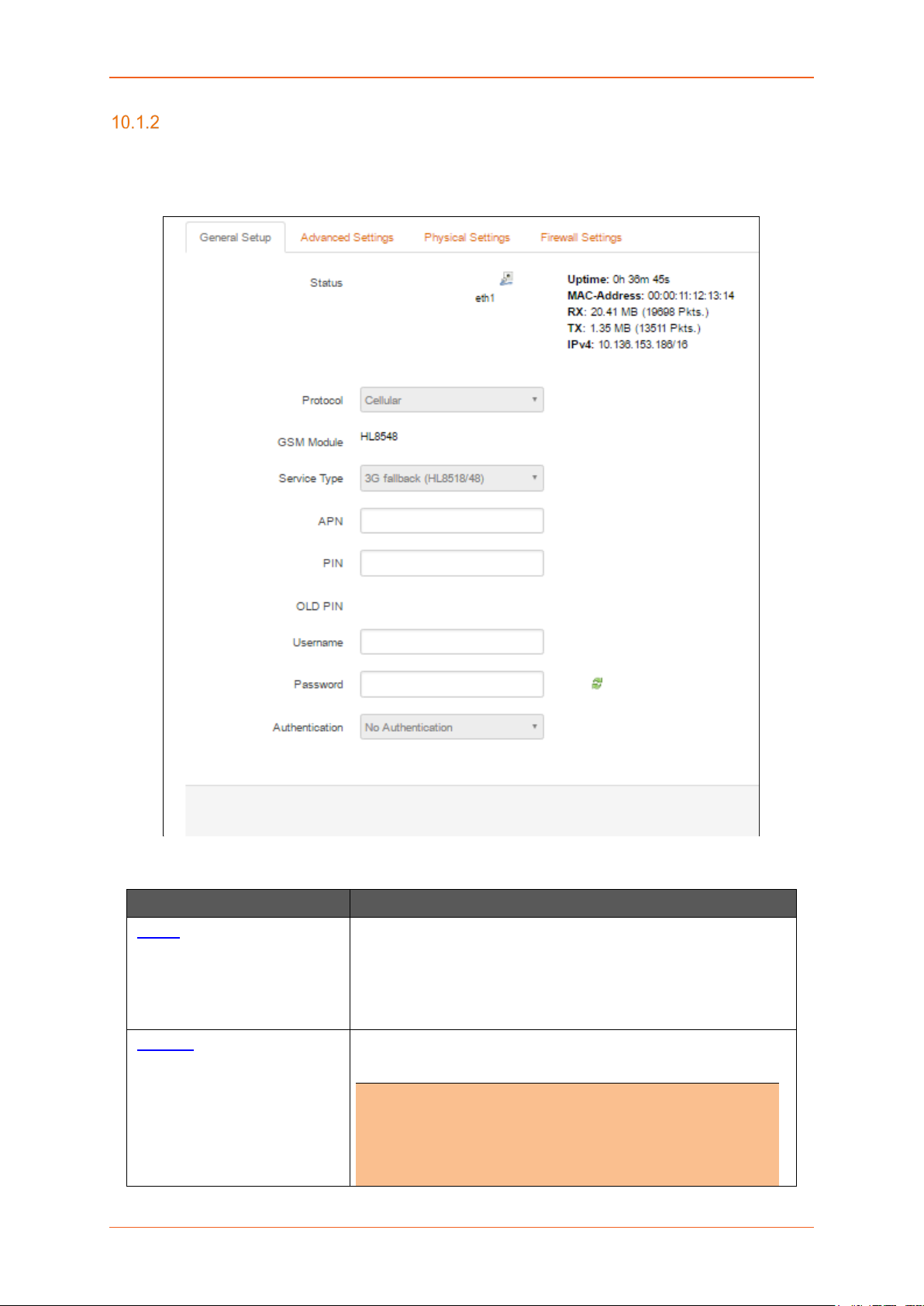
UMTS/GPRS
• Protocol – Select the protocol with respect to the router
model number.
• Service Type – Select the type of service from the
available. You can sele ct i f y ou want 2G only, 3G only, 3G
with 2G fallback, 4G only and 4G with 3G or 2G fallback.
Please note that this selections largely depends on the
Router Model.
• APN – Enter the APN provided by your network operator.
• PIN – Enter the SIM PIN if any.
• Username – Enter the Username for APN access if ex ists.
• Password – Enter the Password Username for APN
access if exists.
• Authentication – Enter t he type of authen tication that your
cellular operator provided for PPP negotiation from
PAP/CHAP/No Authentication
CELLULAR
• Priority – Select the service from the available o ptions that
are AT&T, GenericGSM, GenericCDMA, Sprint and
Verizon.
• Delay – Enter the delay in second/minutes for the Cellular
Module to reboot post the selection of the service from
parameter Priority.
• APN – Enter the APN provided by your network operator.
• PIN – Enter the SIM PIN if any
• Username – Enter the Username.
• Password – Enter the Password.
(E206)
E220 Series Cellular Router User Guide 68
Page 69

Network
Interface Overview
Network > Interface > Interface Overview
Screen 10-1: Interface Overview
Parameters Description
Interface Overview
Network Displays the all the configured Network Interfaces. The pre-
configured interfaces for the router are
• LAN
• CELLDHCP (Only for E206)
• CELLULAR (Only for E206)
• WAN
• WWAN
Note
• Default Interfaces LAN, Cellular, WAN, WWAN cannot be
deleted.
• When Wi-Fi is configured as Client, Interface WWAN will
become active.
E220 Series Cellular Router User Guide 69
Page 70

Network
Parameters Description
Status Displays the following Interface details:
• Uptime
• MAC-Address
• RX
• TX
• IPv4
• IPv6
Actions Select the action to be taken for the Interface.
• Connect – Connects the interface or reconnects the
already connected interface
• Stop – Stops the Interface
• Edit – Click to edit the Interface.
Add VPN Interface Click to add and configure the virtual interfaces.
Note
• Adding a Virtual Interface may require complex
configuration modifications in load balancer settings. For
more details, please visit Lantronix Technical Support.
Global Network Options
IPv6 ULA-Prefix Displays the IPv6 ULA-Prefix
Network Watchdog
Enable Click to enable Network Watchdog.
Watchdog keeps a check on the connectivity of all WAN interfaces.
In absence of the connectivity resulting in Network down, the router
resets itself.
By default, the network watchdog is in disable mode.
Table 10.1-1: Interface Overview
E220 Series Cellular Router User Guide 70
Page 71

Network
A. Add VPN Interface
Note
• Adding a Virtual Interface may require complex configuration modifications in load
balancer settings. For more details, please visit Lantronix Technical Support.
Screen 10-2: Configure VPN Interface
Parameters Description
Name of the new interface Enter the name of the new VPN Interface.
The name must include only alpha numeric characters and special
character underscore ( _ ).
Protocol of the new interface Select the protocol of the new Interface from the available options:
• Static address
• DHCP Client
• Unmanaged
• PPtP
• PPPoE
• UMTS/GPRS (Only for E205)
• CELLULAR (Only for E206)
Create a bridge over multiple
interface
Cover the following interfaces Select the interface to be configured.
Click to enable creating a bridge over multiple interfaces.
E220 Series Cellular Router User Guide 71
Page 72

Network
Parameters Description
Select more than one interface, if a parameter creating a bridge over
multiple interfaces is enabled.
Back to Overview Click to return to Interface Overview page.
Table 10.1-2: Configure VPN Interface
E220 Series Cellular Router User Guide 72
Page 73
Network
3G (Only for E205)
Network > Interface > 3G
A. General Setup
Screen 10-3: General Configurations for 3G Interface
Parameters Description
Status Enter the following Interface details:
• Uptime
• RX
• TX
• IPv4
Protocol Select the protocol with respect to the router model number.
Note
• Be absolutely sure that to select protocol
i. E205 - UMTS/GPRS
ii. E206 - UMTS/GPRS or EVDO
E220 Series Cellular Router User Guide 73
Page 74

Network
•
.
Parameters Description
DO NOT select any other protocol
Service Type Select the type of service from the available:
• 2G only – The router connects only to 2G network.
• 3G only – The router conne ct s only to 3G /UM TS network.
• 3G fallback – The router connects to 3G network
whenever available and fails over to 2G in absence of a
3G network.
• 4G only – The router will connect only to 4G network
• 4G fallback – The router connects to 4G network
whenever available and fails over to 3G/2G in absence of
a 4G network.
•
APN Enter the APN provided by your network operator.
PIN Enter the SIM PIN if any.
Old Pin Displays the previously set SIM PIN if any
PAP/CHAP Username Enter the Username for the Data connection if any.
PAP/CHAP Password Enter the Password for the Data connection if any.
Click to reveal and verify the password. Click it again to hide the
password and secure it.
Authentication Select the authentication type followed by your network operator
from PAP/CHAP/No Authentication
Table 10.1-3: General Configurations for 3G Interface
E220 Series Cellular Router User Guide 74
Page 75

Network
B. Advanced Settings
Screen 10-4: Advanced Configurations for Cellular Interface
Parameters Description
Bring up on boot Allows the Cellular interface to be live after every reboot.
Bring up on boot for Cellular interface is checked by default.
Use builtin IPv6 –management Allows to use the built in IPv6 management configuration.
Enable IPv6 negotiation on
PPP link
Modem init timeout Enter the maximum wait time in seconds for the modem to become
Click to enable IPv6 negotiation on PPP link.
ready.
The default modem initiation timeout 20 seconds.
Use default gateway Click to configure a default gat eway route.
None of the gateway routes are configured by default.
Use gateway metric Enter the gateway metric.
The default metric is 7.
Use DNS server advertised by
peer
Allows the router to advertise the DNS server address.
Use DNS server advertised by peer for Cellular interfa ce is c hec ked
by default.
E220 Series Cellular Router User Guide 75
Page 76

Network
Parameters Description
LCP echo failure threshold Presume peer to be dead after configured LCP echo failures. Use 0
to ignore failures
LCP echo interval This is time the router should wait before sending an echo request to
check whether the link is alive or not.
The LCP echo interval by default is 20 seconds.
Inactivity timeout The Router will wait for the LCP echo request response for the LCP
Echo interval defined after every attempt. It declares LCP link as
closed if it does not receive response after this defined period of
attempts
Use 0 seconds to persist the connection.
Table 10.1-4: Advanced Configurations for 3G Interface
E220 Series Cellular Router User Guide 76
Page 77

Network
C. Firewall Settings
Screen 10-5: Firewall Configuration for 3G
Parameters Description
Create/Assign firewall -zone Select the firewall zone to be assigned to the interface.
Select unspecified – or – create to r emov e the inter f ac e or assign a
new zone to the interface respectively.
Enter the name of the new zone in the text box and click Save &
Apply button.
By default, there are two Firewall Zones, LAN and WAN.
Note
• Every interface must be assigned to a Firewall Zone.
• Failure to assign an interface to a Firewall Zone will render
the interface inactive.
Table 10.1-5: Firewall Configuration for 3G
E220 Series Cellular Router User Guide 77
Page 78

Network
CELLDHCP (Only for E206)
Network > Interface > CELLDHCP
A. General Setup
Screen 10-6: General Configuration of CELLDHCP Interface
Parameters Description
Status Enter the following Interface details
• RX
• TX
Protocol Select the protocol with respect to the router model number. To
update the CELLULAR protocol, select the protocol and click Switch
Protocol button.
The default protocol is CELLULAR.
Table 10.1-6: General Configuration of CELLDHCP Interface
E220 Series Cellular Router User Guide 78
Page 79

Network
B. Advanced Settings
Screen 10-7: Advance Configuration of CELLDHCP Interface
Parameters Description
Bring up on boot Allows the 3G interface to be live after every reboot.
Bring up on boot for 3G interface is checked by default.
Use builtin IPv6 -management Allows to use the built in IPv6 management configuration.
Enable IPv6 negotiation on Click to enable IPv6 negotiation on PPP link.
E220 Series Cellular Router User Guide 79
Page 80

Network
PPP link
Parameters Description
Modem init timeout Enter the maximum wait time in seconds for the modem to become
ready.
The default modem initiation timeout 20 seconds.
Use default gateway Click to configur e a default gateway route.
None of the gateway routes are configured by default.
Use gateway metric Enter the gateway metric.
The default metric is 1.
Use DNS server advertised by
peer
LCP echo failure threshold Presume peer to be dead after configured LCP echo failures. Use 0
LCP echo interval This is time the router should wait before sending an echo request to
Allows the router to advertise the DNS server address.
Use DNS server advertised by peer for 3G interface is checked by
default.
to ignore failures.
check whether the link is alive or not.
The LCP echo interval by default is 20 seconds.
Inactivity timeout The Router will wait for the LCP echo request response for the LCP
Echo interval defined after every attempt. It declares LCP link as
closed if it does not receive response after this defined period of
attempts
Use 0 seconds to persist the connection.
Table 10.1-7: Advance Configuration of CELLDHCP Interface
E220 Series Cellular Router User Guide 80
Page 81

Network
C. Firewall Settings
Screen 10-8: Firewall Configuration of CELLDHCP Interface
Parameters Description
Create/Assign firewall –zone Select the firewall zone to be assigned to the interface.
Select unspecified – or – create to remove the interface or assign a
new zone to the interface respectively.
Enter the name of the new zone in the text box and click Save &
Apply button.
Table 10.1-8: Firewall Configuration of CELLDHCP Interface
E220 Series Cellular Router User Guide 81
Page 82
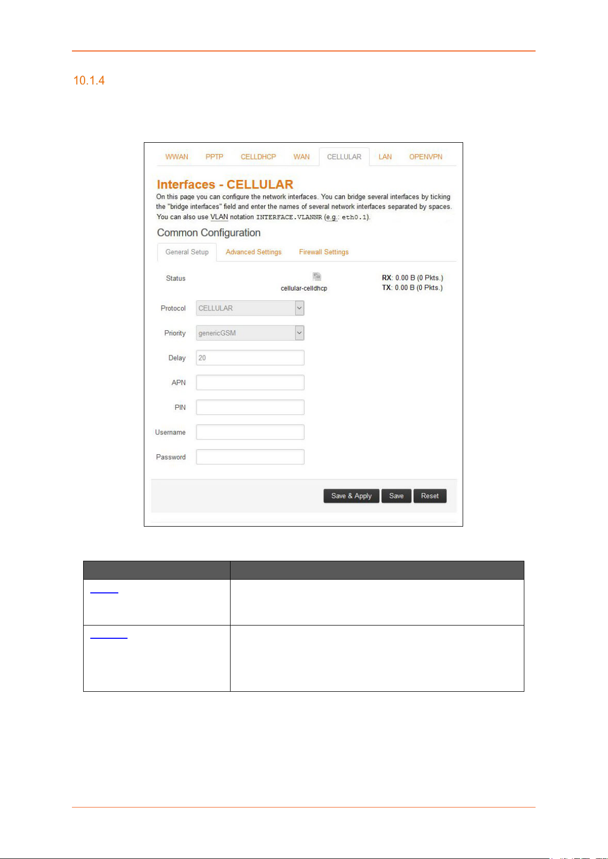
Network
CELLULAR
Network > Interface > CELLULAR
A. General Setup
Screen 10-9: General Configuration of CELLULAR Interface
Parameters Description
Status Enter the following Interface details
• RX
• TX
Protocol Select the protocol with respect to the router model number. To
update the CELLULAR protocol, select the protocol and click Switch
Protocol button.
The default protocol is CELLULAR.
Table 10.1-9: General Configuration of CELLULAR Interface
E220 Series Cellular Router User Guide 82
Page 83

Network
B. Advanced Settings
Screen 10-10: Advance Configuration of CELLULAR Interface
Parameters Description
Bring up on boot Allows the 3G interface to be live after every reboot.
Bring up on boot for 3G interface is checked by default.
Use builtin IPv6 -management Allows to use the built in IPv6 management configuration.
Enable IPv6 negotiation on
PPP link
Modem init timeout Enter the maximum wait time in seconds for the modem to become
Click to enable IPv6 negotiation on PPP link.
E220 Series Cellular Router User Guide 83
Page 84

Network
ready.
Parameters Description
The default modem initiation timeout 20 seconds.
Use default gateway Click to configur e a default gateway route.
None of the gateway routes are configured by default.
Use gateway metric Enter the gateway metric.
The default metric is 5.
Use DNS server advertised by
peer
LCP echo failure threshold Presume peer to be dead after configured LCP echo failures. Use 0
LCP echo interval This is time the router should wait before sending an echo request to
Allows the router to advertise the DNS server address.
Use DNS server advertised by peer for 3G interface is checked by
default.
to ignore failures.
check whether the link is alive or not.
The LCP echo interval by default is 20 seconds.
Inactivity timeout The Router will wait for the LCP echo request response for the LCP
Echo interval defined after every attempt. It declares LCP link as
closed if it does not receive response after this defined period of
attempts
Use 0 seconds to persist the connection.
Table 10.1-10: Advance Configuration of CELLULAR Interface
E220 Series Cellular Router User Guide 84
Page 85

Network
C. Firewall Settings
Screen 10-11: Firewall Configuration of CELLULAR Interface
Parameters Description
Create/Assign firewall -zone Select the firewall zone to be assigned to the interface.
Select unspecified – or – create to remove the interface or assign a
new zone to the interface respectively.
Enter the name of the new zone in the text box and click Save &
Apply button.
Table 10.1-11: Firewall Configuration of CELLULAR Interface
E220 Series Cellular Router User Guide 85
Page 86

Network
WAN
Network > Interface > WAN
A. General Setup
Screen 10-12: General Configurations for WAN Interface
Parameters Description
Status Enter the following Interface details:
• Uptime
• MAC–Address
• RX
• TX
• IPv4
Protocol Select the protocol with respect to the router model number. To
update the WAN protocol, select the protocol and click Switch
Protocol button.
DHCP client is the default protocol.
Table 10.1-12: General Configurations for WAN Interface
E220 Series Cellular Router User Guide 86
Page 87

Network
B. Advanced Settings
Screen 10-13: Advanced Configurations of WAN Interface
Parameters Description
Bring up on boot Allows the WAN interface to be live after every reboot.
Bring up on boot for WAN interface is checked by default.
Use builtin IPv6 -management Allows to use the built in IPv6 management configuration.
Use broadcast flag Check to use the broadcast flag.
This flag is generally used by the ISP’s.
E220 Series Cellular Router User Guide 87
Page 88

Network
Parameters Description
Use default gateway Click to configur e a default gateway route.
None of the gateway routes are configured by default.
Use DNS server advertised by
peer
Use gateway metric Enter the gateway metric. It ensures a separate routing entry for the
Client ID to send when
requesting DHCP
Vendor Class to send when
requesting DHCP
Override MAC address Click to override the default MAC Address for the WAN Interface.
Overrride MTU Click to override the default MTU value (Maximum Transmission
Allows advertising the DNS server address.
Use DNS server advertised by peer for WAN interface is checked by
default.
If unchecked, the advertised DNS server addresses are ignored.
respective interface in the main routing table.
The default metric is 3.
Enter the Client ID that shall be sent when requesting DHCP.
To allocate DHCP IP Addresses based on Vendor Class.
On factory reset, it will be set to default MAC address.
Unit)
The default MTU is 1500.
Table 10.1-13: Advanced Configurations of WAN Interface
E220 Series Cellular Router User Guide 88
Page 89

Network
C. Physical Settin gs
Screen 10-14: Physical Configurations for WAN interface
Parameters Description
Bridge Interfaces Click to enable creating a bridge over multiple interfaces.
Enable STP – Check to enable the Spanning Tree Protocol over the
bridge.
Interface Select the interface to be configured.
Select more than one interface, if parameter creating a bridge over
multiple interfaces is enabled.
Table 10.1-14: Physical Configurations for WAN interface
E220 Series Cellular Router User Guide 89
Page 90

Network
D. Firewall Settings
Screen 10-15: Firewall Configurations for WAN Interface
Parameters Description
Create/Assign firewall -zone Select the firewall zone to be assigned to the interface.
Select unspecified – or – create to r emov e the inter f ac e or assign a
new zone to the interface respectively.
Enter the name of the new zone in the text box and click Save &
Apply button.
Table 10.1-15: Firewall Configurations for WAN Interface
E220 Series Cellular Router User Guide 90
Page 91

Network
LAN
Network > Interface > LAN
A. General Setup
Screen 10-16: General Configurations of LAN Interface
E220 Series Cellular Router User Guide 91
Page 92

Network
Parameters Description
Status Displays the following Interface details:
• Uptime
• MAC–Address
• RX
• TX
• IPv4
• IPv6
Protocol Select the protocol with respect to the router model number. To
update the WAN protocol, select the protocol and click Switch
Protocol button.
Static Address is the default protocol.
Table 10.1-16: General Configurations of LAN Interface
E220 Series Cellular Router User Guide 92
Page 93

Network
B. Advanced Settings
Screen 10-17: Advanced Settings for LAN Interface
Parameters Description
Bring up on boot Allows the WAN interface to be live after every reboot.
Bring up on boot for WAN interface is checked by default.
Use builtin IPv6 -management Allows to use the built in IPv6 management configuration.
Override MAC address Click to override the default MAC Address for the WAN Interface.
On factory reset, it will be set to default MAC address.
Overrride MTU Click to override the default MTU value (Maximum Transmission
Unit)
The default MTU is 1500.
Use gateway metric Enter the gateway metric.
The default metric is 0.
Table 10.1-17: Advanced Settings for LAN Interface
E220 Series Cellular Router User Guide 93
Page 94

Network
C. Physical Settin gs
Screen 10-18: Physical Configurations of LAN Interface
Parameters Description
Bridge Interfaces Click to enable creating a bridge over multiple interfaces.
Enable STP – Check to enable the Spanning Tree Protocol over the
bridge.
Interface Select the interface to be configured.
Select more than one inter f ace if paramet er creat ing a br idge ov er
multiple interfaces is enabled.
Table 10.1-18: Physical Configurations of LAN Interface
E220 Series Cellular Router User Guide 94
Page 95

Network
D. Firewall Settings
Screen 10-19: Firewall Configurations of LAN Interface
Parameters Description
Create/Assign firewall -zone Select the firewall zone to be assigned to the interface.
Select unspecified – or – create to r emov e the inter f ac e or assign a
new zone to the interface respectively.
Enter the name of the new zone in the text box and click Save &
Apply button.
Table 10.1-19: Firewall Configurations of LAN Interface
E220 Series Cellular Router User Guide 95
Page 96

Network
E. DHCP Server
The DHCP server maintains a database of available IP addresses and configuration information. When
it receives a request fr om a client, t he DHCP s erver determ ines the network to whi ch the DHC P client
is connected, and alloca tes an IP a ddress or pr efix appr opriate f or the client, and sends c onfiguration
information appropriate for that client.
DHCP servers typica ll y gra nt IP addres s es t o c lie nts f or a limited interval called a leas e. DHCP clients
are responsible for renewing their IP address before that interval has expired, and must stop using the
address once the interval h as expired, if the y have not been able to renew it. DH CP is used for IPv4
and IPv6. While both versions serve the same purpose, the details of the protocol for IPv4 and IPv6 are
sufficiently different that they should be considered separate protocols.
The router acts as the DHCP server and assigns the IP Address to device(s) connected to the network.
E220 Series Cellular Router User Guide 96
Page 97

Network
a. General Setup
Screen 10-20: General Configurations for DHCP Server
Parameters Description
Ignore Interface Check to disable the DHCP interface.
Note
• If DHCP is disabled for this interface, all the LAN devices
connected to the router should have a static LAN IP
configured.
Start Lowest leased address as offset from the network address.
Example – if your LAN IP address is 192.168.1.1 and the paramet er
Start is configured as 100, then the starting IP Address of the leased
IP Address range is 192.168.1.100
Limit Maximum number of leased addresses that can be configured.
Example – if your LAN IP Address is 192.168.1.1, the parameter
Start is configured as 100, and parameter Limit is configured as
150, then a total of 150 devices are configured. Thus the leased IP
Address range is 192.168.1.100 to 192.168.1.249.
Leasetime Remaining time until which the device can use the DHCP server
leased IP Address.
Note
• IP address allocated by the router will disappear from the
Wi-Fi / Overview / Associates stations list only after
individual lease time for each IP expires.
Table 10.1-20: General Configurations for DHCP Server
E220 Series Cellular Router User Guide 97
Page 98

Network
b. Advanced Settings
Screen 10-21: Advance Configurations for DHCP Server
Parameters Description
Dynamic DHCP Check to allocate DHCP IP addresses dynamically to the clients.
When unchecked, service will be provided only to the clients having
the static IP Address.
Force Check to override the current configured Server and use DHCP
server.
IPv4-Netmask Enter the IPv4 netmask.
This netmask will override the netmask used by the clients. In
normal scenario netmask is calculated from the subnet.
DHCP-Options Define additional DHCP options,
Example – "6,192.168.2.1, 192.168.2.2" which advertises different
DNS servers to clients.
Table 10.1-21: Advance Configurations for DHCP Server
E220 Series Cellular Router User Guide 98
Page 99

Network
c. IPv6 Settings
Screen 10-22: IPv6 Configuration of DHCP Server
Parameters Description
Router Advertisement-Service Select the Router Advertisement-Service mode; disabled, server
mode, relay mode, hybrid mode.
DHCPv6-Service Sele ct the DHCPv6-Service mode; disabled, server mode, relay
mode, hybrid mode.
NDP-Proxy Select the NDP mode; disabled, server mode, relay mode, hybrid
mode.
DHCPv6-Mode Select the DHCPv6-Service mode:
• Stateless
• Stateful
• Stateless + Stateful
• Stateful only
Always announce default
router
Announced DNS servers Add the DNS servers
Announced DNS domains Add the DNS domains.
If ticked Announce as default router even if no public prefix is
available.
Table 10.1-22: IPv6 Configuration of DHCP Server
E220 Series Cellular Router User Guide 99
Page 100

Network
WWAN
Network > Interface > WWAN
A. General Setup
Screen 10-23: General Configuration for WWAN Interface
Parameters Description
Status Enter the following Interface details:
• Uptime
• MAC–Address
• RX
• TX
• IPv4
Protocol
Select the protocol with respect to the router model number. To
update the WAN protocol, select the protocol and click Switch
Protocol button.
DHCP client is the default protocol.
Note
• We recommend to select either DHCP or Static Address,
PPPoE or PPPoATM
Table 10.1-23: General Configuration for WWAN Interface
E220 Series Cellular Router User Guide 100
 Loading...