

Page 1
E210 Series
Part Number PMD-00017
Revision B February 2021
Cellular Router
User Guide
Page 2

Intellectual Property
© 2019-2021 Lantronix, Inc. All rights reserved. No part of the contents of this
publication may be transmitted or reproduced in any form or by any means without
the written permission of Lantronix.
Lantronix is a registered trademark of Lantronix, Inc. in the United States and other
countries.
Patented: https://www.lantronix.com/legal/patents/
Windows and Internet Explorer are registered trademarks of Microsoft Corporation.
Firefox is a registered trademark of the Mozilla Foundation. Chrome is a trademark of
Google Inc. All other trademarks and trade names are the property of their respective
holders.
Warranty
For details on the Lantronix warranty policy, please go to our web site at
https://www.lantronix.com/support/warranty
Contacts
Lantronix, Inc.
7535 Irvine Center Drive, Suite 100
Irvine, CA 92618, USA
Toll Free: 800-526-8766
Phone: 949-453-3990
Fax: 949-453-3995
. Additional patents pending.
.
Technical Support
Online: www.lantronix.com/support
Sales Offices
For a current list of our domestic and international sales offices, go to the Lantronix
web site at www.lantronix.com/about-us/contact
Disclaimer
All information contained herein is provided “AS IS.” Lantronix undertakes no
obligation to update the information in this publication. Lantronix does not make,
and specifically disclaims, all warranties of any kind (express, implied or otherwise)
regarding title, non-infringement, fitness, quality, accuracy, completeness,
usefulness, suitability or performance of the information provided herein. Lantronix
shall have no liability whatsoever to any user for any damages, losses and causes
of action (whether in contract or in tort or otherwise) in connection with the user’s
access or usage of any of the information or content contained herein. The
information and specifications contained in this document are subject to change
without notice.
E210 Series Cellular Router User Guide 1
Page 3

Date
Rev.
Comments
1.4
Open Source Software
Some applications are Open Source software licensed under the Berkeley
Software Distribution (BSD) license, the GNU General Public License (GPL) as
published by the Free Software Foundation (FSF), or the Python Software
Foundation (PSF) License Agreement for Python 2.7.3 (Python License). Lantronix
grants you no right to receive source code to the Open Source software; however,
in some cases, rights and access to source code for certain Open Source software
may be available directly from Lantronix’ licensors. Your use of each Open Source
component or software is subject to the terms of the applicable license. The BSD
license is available at http://opensource.org/licenses
License is available at http://www.gnu.org/licenses/. The Python License is
available at http://cmpt165.csil.sfu.ca/Python-Docs/license.html. Your use of each
Open Source component or software is subject to the terms of the applicable
license.
OPEN SOURCE SOFTWARE IS DISTRIBUTED WITHOUT ANY WARRANTY,
INCLUDING ANY IMPLIED WARRANTY OF MERCHANTABILITY OR FITNESS
FOR A PARTICULAR PURPOSE. SEE THE APPLICABLE LICENSE
AGREEMENT FOR ADDITIONAL INFORMATION.
You may request a list of the open source components and the licenses that apply
to them. Contact your regional Lantronix sales associate.
https://www.lantronix.com/about-us/contact/
. The GNU General Public
Revision History
Sep., 2017 1.0 First release
Oct., 2017 1.1 RAM size and model list
Nov., 2017 1.2 Compatible models
Jun., 2018 1.3 Compatible models
Apr., 2019
October 2019 A Initial Lantronix document.
Power consumption, Accessories and LED Status Indicator.
Added Lantronix document part number, Lantronix logo, branding,
contact information, and links.
February 2021 B
Updated the compatible models, accessories, LED states, reset
button behavior, physical installation procedures, default login
credentials, and Web Admin console screenshots.
Reorganized content and made document enhancements.
For the latest revision of this product document, please check our online
documentation at www.lantronix.com/support/documentation
.
E210 Series Cellular Router User Guide 2
Page 4

Contents
1 Safety Precautions 4
1.1 General Precautions ________________________________________ 4
1.2 Using the Router in Vehicles __________________________________ 4
1.3 Protecting Your Router_______________________________________ 4
2 About this Guide 5
2.1 Purpose and Audience _______________________________________ 5
2.2 Additional Documentation ____________________________________ 5
3 E210 Series Compatible Models 6
4 Product Features 7
4.1 General Specification ________________________________________ 7
4.2 Power Consumption (mA) ____________________________________ 7
4.3 Back Panel Connections _____________________________________ 9
4.4 Front Panel Connections ____________________________________ 10
4.5 LED Status Indicators ______________________________________ 11
5 Installation 12
5.1 Package Contents _________________________________________ 12
5.2 User Supplied Items ________________________________________ 12
5.3 Optional Add-on ___________________________________________ 12
5.4 Accessories ______________________________________________ 12
5.5 Preparing to Install _________________________________________ 14
5.5.1 Enabling DHCP on Your Personal Computer ________________ 14
5.6 Connecting the E210 Router _________________________________ 15
5.6.1 Insert SIM Cards ______________________________________ 15
5.6.2 Connect the Antennas _________________________________ 16
5.6.3 Connect the AC Power _________________________________ 17
5.6.4 Connect the Router to a Computer _______________________ 17
5.6.5 Quick Setup _________________________________________ 19
5.6.6 Default Configuration __________________________________ 21
5.6.7 SNAP CAP™ RS-485 __________________________________ 22
E210 Series Cellular Router User Guide 3
Page 5

1 Safety Precautions
1.1 General Precautions
The router generates radio frequency (RF) power. When using the router, care must be taken
to ensure safety as well as compliance with all the regulations that surround the use of RF
equipment.
Do not use the router in aircraft, hospitals and petrol stations or in places where using GSM,
W-CDMA and LTE equipment or any other RF equipment is prohibited, and make sure that
the router is not interfering with nearby equipment such as pacemakers or medical
equipment.
All antennas of the router should be directed away from computers, office equipment, home
appliances, etc., and always keep the router at a minimally safe distance of 26.6cm or more
from human bodies.
Do not put the antenna inside metallic boxes or other containers.
1.2 Using the Router in Vehicles
Check for regulations/law, if any, for authorizing the use of GSM, W-CDMA and LTE
equipment in vehicles in your country before installing the router.
Installation of the router should be done by qualified personnel. Consult your vehicle dealer
for any possible interference concerns to the use of the router.
Battery of the vehicle could be drained after an extended period when the router is powered
by the vehicles main battery.
1.3 Protecting Your Router
Please install and operate the router with care, and complying the following;
Do not expose the router in extreme conditions such as high humidity/rain, high temperature,
direct sunlight, caustic/harsh chemicals, dust, or water.
Do not try to disassemble or modify the router as there is no user serviceable parts inside and
the warranty would be voided in the case of tampering.
Do not drop, hit, shake the router in extreme vibrations.
Do not pull the power supply cable. Please attach or detach it by holding the connector after
switching off the supply.
Install and connect the router in accordance with this document.
Failure to do so will void the warranty.
E210 Series Cellular Router User Guide 4
Page 6

2: About this Guide
Document
Description
E210 Series Cellular Router
Provides hardware installation instructions,
ePack User Guide for E210
Provides the information needed to configure and
E210 Series Product Brief
Provides E210 series router product overview
2 About this Guide
2.1 Purpose and Audience
This guide provides the information needed to install the Lantronix E210 series cellular router.
It covers hardware features, installation instructions, and network IP configuration information.
This document does not cover how to configure your E210 series cellular router.
The information in this document assumes that the reader has working knowledge of
networking (Ethernet, LAN), routing, LTE, and GNSS concepts and terminology.
2.2 Additional Documentation
Visit the Lantronix web site at https://www.lantronix.com/support/documentation for the latest
documentation and the following additional documentation for this product series.
Quick Start Guide
and E220 Series Devices
directions to connect the E210 series router, and
network IP configuration information.
use the ePack software for the Lantronix E210
series and Lantronix E220 series cellular routers.
information and specifications.
E210 Series Cellular Router User Guide 5
Page 7
MODEL
C
3
E215
EMEA; South-East Asia; South Asia
3G
ζ1
8/1
2G
λ1
8/3 EN300328 | ETA, TEC
Aug. ’18
E215F002S
FCC, IC, CE, PTCRB, AT&T Wireless,
Australia & New Zealand; T hailand;
EMEA; Asia Pacific
28/20/8/3/1/7
CE 7
E214F002S
China; Thailand; Indones ia; India
5/8/3/1; TDD 40/4 1f
ETA, TEC | SRRC, CTA; Postel
E214F00CS
Verizon Wireless
13/4
N/A FCC 8, Verizon Wireless
E214G001S
The Americas – excl. Ve rizon Wireless
12/5/4/2
3G
ζ3
5/4/2
FCC 8, PTCRB, AT&T Wireless; ISE D
E214G000S
Brazil; Australia & New Z ealand; Thailand
28/5/8/3/1/7
3G
ζ3
; 2G
λ3
5/8/1; 8/3
Optional
NBTC
Mar. ’19
E218F004S
NTT docomo
19/21/1
-
May ’19
E218F005S
E213
450 MHz operators
LTE-M1 6
Postel
tbd
E213F10ES
USA & Canada
FCC 8, PTCRB; ISED
tbd
E214G10AS
Japan; South Korea
JRF, JPA; KC
tbd
E214G107S
E218
EMEA; Asia Pacific
LTE cat. 4
3G
; 2G
8/1; 8/3
Optional
CE; RCM; NCC
tbd
E218F102S
1
Uplink / Downlink maximum data rates
2
Ranked by increasing frequencies
3
Please consult us, should any other certification be required
- 2G: λ1 85.6 / 23 6.8; or λ2 236.8 / 23 6.8; or λ3 236.8 / 296 kbps
a
incl. North America’s B17
4
First customer shipment [date of]
- 3G: ζ1 5
.76
/ 7.2; or ζ2 5
.76
/ 10.1; or ζ3 5
.76
/ 42.2 Mbps
b
incl. KDDI’s B18 as well as North America’s B5, the latter
5
23 dBm output power
- LTE -M1 [NB1]: 375 / 300 [62.5 / 27.2] kbps
c
incl. NTT docomo’s B1 9, itself inc l. Japan’s B6 (3G)
6
26 dBm outp ut power from 410 MHz to 467.5 MHz, 23 dBm otherwise
updated to LTE-M2 [NB2]: 1,000 / 600 [140 / 120] kbps
incl. Japan’s B9
- LTE cat. 1: 5 / 10 Mbps (FDD); 3.1 / 8
.96
Mbps (TDD)
d
incl. N orth America’s B10, itself incl. North Ame rica’s B4
8
Also, Clas s I Division 2 for use i n explosive a tmospheres,
as a factory option su bject to MOQ and other considera tions
f
More precisely, B41’s 2535 MHz ~ 2655 MHz subset, suited to
China well
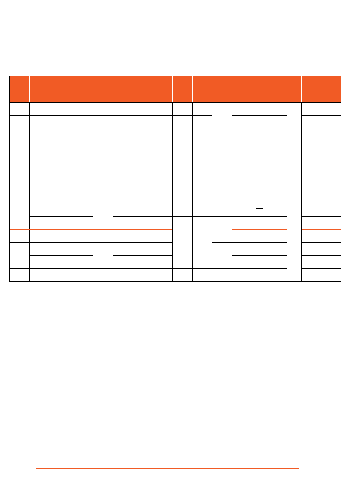
NAME
3: E210 Series Compatible Models
3 E210 Series Compatible Models
GEOGRAPHICAL AREA(S) /
OPERATOR
CELLULAR
1
TYPE
BANDS 2
FALLBACK
MODE(S)
1
BANDS 2
LOCATION
SERVICES
ERTIFICATIONS
COMPLETED | IN PROGRESS | UNDER
CONSIDERATION
FCS 4
ORDER
CODE
E213 World LTE-M1 5 12a/28/13/20/27/2 6b/8/3c/66d/25e/1 2G 5/8/3/2
Malaysia
28/5/8/3 3G
ζ2
5/8/1 RCM; Aug. ’18 E214F003S
E214
ζ3
λ3
3G
; 2G
LTE cat. 1
8/1; 8/3 Optional
E214G
E218
E214G
LTE cat. 4
LTE cat. 1
87 TBC/88 TBC/73/72/31/
12a/28/13/20/27/26b/8/3c/66d/25e/1
71/12/13/14/26(5)/66(4)/25(2)
N/A
18/5(19)/8/21/3/1/7
ζ3
28/20/8/3/1/7
λ3
Table 3-1: E210 Series Compatible Models
Please consult us regarding the models or features shown in grey i talics, which ar e subject to MOQ and other considerations
Verizon Wireless
TBD E213F10 2S
Dec. ’18
MIL-STD-810H
Nov. ’18
9
- LTE cat. 4: 50 / 150 Mbps (FDD); 35 / 130 Mbps (TDD)
•
E210 Series Cellular Router User Guide 6
7
Based on compliance with RED; EN 60950-1 ; etc.
e
incl. North America’s B2
9
by Switzerland’s SGS
Page 8

4: Product Features
E213
E214#358S#158
E214G#00
4 Product Features
4.1 General Specification
Component Specification
Casing Brushed aluminium alloy
Dimensions 92.5 x 57.2 x 22.5 mm (without connectors)
Weight 150 g (approx.)
Operating temperature -20 °C ~ +60 °C; up to 95 % R.H.
Storage temperature -40 °C ~ +85 °C; up to 95 % R.H.
Flash memory (SPI) 32 MB
RAM (DDR2 SD-RAM): 128 MB
Ethernet 10/100BASE-T
Wi-Fi IEEE 802.11b/g//n 2.4 GHz
GPS IZat™ gen. 8C gpsOne
Table 4-1: General Specification
4.2 Power Consumption (mA)
Device State 8V 12V 32V
Idle (WLAN, LAN, Wi-Fi, RS-232 & TF card disconnected, cellular
module off)
Stand-by (WLAN, LAN, Wi-Fi, RS-232 & TF card disconnected,
cellular module idle)
Stand-by (WLAN, LAN, Wi-Fi, RS-232 & TF card connected,
cellular module idle)
GPRS (2Tx,3Rx)@900/850MHz (PCL=5) 530 356 135
LTE in communication mode (Tx max.) 420 283 108
Idle (WLAN, LAN, Wi-Fi, RS-232 & TF card disconnected, cellular
module off)
165 110 43
265 171 65
356 235 91
118 79 30
E210 Series Cellular Router User Guide 7
Stand-by (WLAN, LAN, Wi-Fi, RS-232 & TF card disconnected,
cellular module idle)
Stand-by (WLAN, LAN, Wi-Fi, RS-232 & TF card connected,
cellular module idle)
W-CDMA in communication mode (Tx max.) 575 386 146
LTE in communication mode (Tx max.) 695 471 179
Idle (WLAN, LAN, Wi-Fi, RS-232 & TF card disconnected, cellular
module off)
145 99 38
270 187 73
137 90 34
Page 9

4: Product Features
E215#02
E218#04
E218G#04
Device State 8V 12V 32V
Stand-by (WLAN, LAN, Wi-Fi, RS-232 & TF card disconnected,
cellular module idle)
Stand-by (WLAN, LAN, Wi-Fi, RS-232 & TF card connected,
cellular module idle)
W-CDMA in communication mode (Tx max.) 650 445 170
LTE in communication mode (Tx max.) 730 495 193
Idle (WLAN, LAN, Wi-Fi, RS-232 & TF card disconnected, cellular
module off)
Stand-by (WLAN, LAN, Wi-Fi, RS-232 & TF card disconnected,
cellular module idle)
Stand-by (WLAN, LAN, Wi-Fi, RS-232 & TF card connected,
cellular module idle)
GSM in communication mode (PCL=5) 380 252 98
GPRS (2Tx,3Rx)@900/850MHz (PCL=5) 450 307 115
W-CDMA in communication mode (Tx max.) 685 456 173
Idle (WLAN, LAN, Wi-Fi, RS-232 & TF card disconnected, cellular
module off)
195 135 51
290 203 82
120 80 29
143 98 37
265 185 72
163 109 42
Stand-by (WLAN, LAN, Wi-Fi, RS-232 & TF card disconnected,
cellular module idle)
Stand-by (WLAN, LAN, Wi-Fi, RS-232 & TF card connected,
cellular module idle)
GSM in communication mode (PCL=5) 450 305 115
GPRS (2Tx,3Rx)@900/850MHz (PCL=5) 600 412 158
W-CDMA in communication mode (Tx max.) 740 491 192
LTE in communication mode (Tx max.) 690 465 177
Idle (WLAN, LAN, Wi-Fi, RS-232 & TF card disconnected, cellular
module off)
Stand-by (WLAN, LAN, Wi-Fi, RS-232 & TF card disconnected,
cellular module idle)
Stand-by (WLAN, LAN, Wi-Fi, RS-232 & TF card connected,
cellular module idle)
GSM in communication mode (PCL=5) 461 313 118
GPRS (2Tx,3Rx)@900/850MHz (PCL=5) 611 420 161
W-CDMA in communication mode (Tx max.) 751 499 195
LTE in communication mode (Tx max.) 701 473 180
250 165 61
335 225 86
163 109 42
261 173 64
346 232 89
Table 4-2: Power Consumption (mA)
E210 Series Cellular Router User Guide 8
Page 10

4: Product Features
4.3 Back Panel Connections
Figure 4-1: Back Panel Connections
1 Wi-Fi antenna, RP SMA connector
2 Cellular diversity antenna, SMA connector
3 GPS antenna, SMA connector
4 Cellular main antenna, SMA connector
5 MicroSD-XD card slot
6 Dual SIM slots, Left: SIM2, Right: SIM1
Note: Depending on the device model, the number of antenna connectors may vary.
E210 Series Cellular Router User Guide 9
Page 11

4: Product Features
4.4 Front Panel Connections
Figure 4-2: Front Panel Connections
DC Power 4-pin Microfit 3.0 connector
Top L/R: 8V ~ 32Vdc
Bottom L/R: Two digital I/Os
1
2
3
Digital Input: 0~1Vdc as low
1~36Vdc as high
Digital Output: Open collector,
100 mA@24Vdc max
RS-232
1. DCD
2. Rx
3. Tx
4. DTR
5. Ground
6. DSR
7. RTS
8. CTS
9. RI
Ethernet ports
Left: LAN
Right: WAN or set as 2
nd
LAN
Reset button – Reset the router back to default settings.
Factory reset – Press and hold the reset button for more than 5 seconds.
4
Reboot – Press and hold the reset button for more than one second but less
than 5 seconds
Note: For any pressed or released event to be detected the duration of the
press/release event must be at least 200ms.
E210 Series Cellular Router User Guide 10
Page 12

4: Product Features
4.5 LED Status Indicators
The E210 operation status is indicated by seven LEDs as shown in the figure and table
below.
Figure 4-3: LED Status Indicators
Name Color and
Status
Wi-Fi OFF Wi-Fi network is inactive
Blue ON Wi-Fi network is activated
Blue Flashing Wi-Fi network data transferring
Activity OFF Cellular data service not connected
Amber ON Cellular data service connected
Amber Flashing Cellular data transferring
Network OFF Not registered on cellular network
Amber ON Registered on cellular network (home)
Amber Flashing Registered on cellular network (roaming)
Signal OFF No signal (CSQ=0 to 5, 97, 98, 99)
Amber Flashing Weak signal (CSQ > 6 to 12)
Amber ON Strong signal (CSQ > 12)
SIM in use Blue ON SIM 1
Flashing SIM 2
Description
Power OFF Power off
Green ON Power on
Alert OFF No alert
Red Flashing Cellular module reboot, kernel rebooting
Red ON Hardware fault
E210 Series Cellular Router User Guide 11
Page 13

5: Installation
5 Installation
5.1 Package Contents
• E210 Series Cellular Router
• E210 Series Quick Start Guide
5.2 User Supplied Items
• SIM cards (activated by mobile network operator)
• Power supply and adapters
• Wi-Fi antenna
• Cellular/GPS antenna
• Ethernet CAT5 cable to connect the router to the network
• DIN rail clip
Please see Accessories for compatible Lantronix cables, adapters, and antennas.
5.3 Optional Add-on
• SNAP CAP™ RS-485 – to convert E210 series router's RS-232 port to
half-duplex or full-duplex RS-485 port
Please consult the SNAP CAP™ RS-485 Datasheet for more details about this add-on.
5.4 Accessories
Lantronix accessories for use with the E210 series router are listed in the table below.
Lantronix accessories are available individually or as accessory bundles. For ordering
information, please refer to the E210 Series product web page or contact Lantronix Sales
Note: Additional accessories for certain geographic locations are available. Please
contact your regional Lantronix Sales office for details.
Lantronix
Part #
Power Supply/Cable/Adapters
P24E0 Europe POWER SUPPLY, 4-PIN MICROFIT 1.2 A POWER ADAPTER, WITH EURO
P24E1 Japan POWER SUPPLY, 4-PIN MICROFIT 1.2 A POWER ADAPTER, WITH JAPAN
P24E2 USA POWER SUPPLY, 4-PIN MICROFIT 1.2 A POWER ADAPTER, WITH USA
E210
Model
Description
PLUG AC CABLE
PLUG AC CABLE WITH PSE MARK
PLUG AC CABLE
.
P24E3 AUS/NZ POWER SUPPLY, 4-PIN MICROFIT 1.2 A POWER ADAPTER, WITH
AUSTRALIA & NZ PLUG AC CABLE
P24E4 UK POWER SUPPLY, 4-PIN MICROFIT 1.2 A POWER ADAPTER, WITH
UK/HONG KONG PLUG AC CABLE
KDC42 all models POWER CABLE, SPARE 4-PIN, W/ POWER FUSE HS
E210 Series Cellular Router User Guide 12
Page 14

5: Installation
Lantronix
Part #
KDC44 all models POWER CABLE, 1-METER, 4-PIN MICRO FIT 3.0 CONNECTOR, 2.4A
Wi-Fi Antenna
A21H0 all models DUAL-BAND 2.4/5.8GHZ DIPOLE ANTENNA FOR ISM & WLAN, HINGED,
A24C0 all models
Cellular/GPS Antenna
A31M0 E215 SINGLE ANTENNA, LTE REMOTE, ADHESIVE, 3-METER RG174 COAX,
A31H0 E215 SINGLE ANTENNA, LTE REMOTE, ADHESIVE, 3-METER COAX, SMA
A14M0 E215G, E213G TWO IN ONE LTE + GNSS, 2*3-METER RG174 CABLE WITH 3*SMA
A14H0 E215G, E213G TWO IN ONE LTE + GNSS, 2*3-METER RG174 CABLE WITH 3*SMA
E210
Model
(while supplies
last)
Description
FUSE, W/ RED/BLACK/BLUE/WHITE CABLES
Note: KDC44 has two more stripped wires for I/Os
RP-SMA (M)
2.4/5.8GHZ WLAN ANTENNA, SMA MALE REVERSE
SMA MALE
MALE
MALE, ADHESIVE MOUNT
MALE, ADHESIVE MOUNT
A32M0 E214,
E218
A32H0 E214,
E218
A33M0 E214G, E218G THREE IN ONE LTE + LTE + GNSS, 2*3-METER RG174 CABLE, SMA MALE
A33H0 E214G, E218G THREE IN ONE LTE + LTE + GNSS, 2*LTE ANTENNA, 2*3-METER CABLE,
Miscellaneous
BR551 all models MOUNTING HARDWARE L-SHAPE DIN CLIP, 1.2MM SPCC; COLOR ZINC-
TWO IN ONE LTE + LTE, 2*3-METER RG174 CABLE, SMA MALE
TWO IN ONE LTE + LTE, 2*3-METER CABLE, SMA MALE, ADHESIVE
MOUNT
SMA MALE, ADHESIVE MOUNT
PLATED; WITH CLIP SPRING, SUS304; WITH SCREW AND WASHER
Table 5-1: Lantronix Accessories
E210 Series Cellular Router User Guide 13
Page 15

5: Installation
5.5 Preparing to Install
Before installation, please gather the router, documentation, and user-supplied items as
needed for your installation.
• One or two activated SIM cards, provided by your mobile network operator
• Ethernet CAT5 cable for LAN network connection
• Wi-Fi and cellular antennas
• Power supply, cable, and adapters
• Personal computer (see below)
See Accessories for compatible Lantronix cables, adapters, and antennas.
Ensure that your personal computer is equipped with the following:
• Ethernet port or Wi-Fi connectivity and Internet service
• Web browser such as Internet Explorer 10+ or Google Chrome 30+, Mozilla Firefox
20+ or Apple Safari 4+ to access the Lantronix Web Admin Console
• DHCP client enabled on the computer to obtain a valid IP Address from the router.
5.5.1 Enabling DHCP on Your Personal Computer
To enable DHCP on Windows 8 or 10:
1. To access the active network, go to Start > Control Panel > Network and Internet >
Network and Sharing Center. Click the active network connection. The Network
Connection Status dialog box appears.
2. From the Network Connection Status dialog, click Properties > select Internet
Protocol Version 4 (TCP/IPv4) and click Properties to display the Internet Protocol
Version 4 (TCP/IPv4) Properties dialog box.
3. On the General tab, select following options:
• Obtain an IP address automatically
• Obtain DNS server address automatically
To enable DHCP on Mac OS:
1. Launch System Preferences, then choose Network.
2. Select Ethernet from the adapters list on the left.
3. Set the Configure IPv4 drop-down to Using DHCP
E210 Series Cellular Router User Guide 14
Page 16

5: Installation
5.6 Connecting the E210 Router
The steps for connecting the E210 router are:
1. Insert the SIM cards.
2. Connect the cellular and Wi-Fi antennas.
3. Connect the AC power.
4. Connect the router to a computer.
5. Run Quick Setup to configure network settings .
5.6.1 Insert SIM Cards
To insert the SIM card:
1. Eject the SIM tray by pushing the yellow eject button inwards.
2. Pull the SIM tray out from the slot.
3. Place the mini-SIM card on the tray with SIM chip facing up.
4. Insert the tray in place carefully.
Figure 5-1: Inserting the SIM Card
E210 Series Cellular Router User Guide 15
Page 17

5: Installation
5.6.2 Connect the Antennas
The table shows the cellular/GPS main and auxiliary antenna options and the
cellular/GPS/Wi-Fi antenna connections on the different E210 series models.
Model Cellular
Main
E213
E215
E214
E218
E214G
Cellular only N/A
Cellular only Cellular only
Cellular only GPS and cellular
Cellular
Auxiliary
Table 5-2: Antenna Options for E210 Series
To connect the Wi-Fi/cellular/GPS antenna:
Antenna connections
1. Insert the antenna connector into the appropriate antenna connector on the back
panel of the router, referring to the image above and the labels printed on the router.
2. Use your fingers to securely tighten (clockwise direction) the antenna connector to
the connector on the base unit.
Note:
• Dual cellular antennas improve data throughput/performance on cellular data
transfer rate.
• Cellular antenna selections are based on frequency bands of cellular network
operators in individual countries. For details, refer to E210 Series Compatible
Models or contact Lantronix Technical Support online.
Figure 5-2: Antenna Connections
E210 Series Cellular Router User Guide 16
Page 18

5: Installation
5.6.3 Connect the AC Power
To connect the AC power:
1. Connect the AC power to the DC in connector, then connect the Micro-Fit connector
to the power input, located on the front panel of the Lantronix Router.
2. Plug the AC cord into a standard AC receptacle as shown below. For connection
details, refer to Section 4.4, Front Panel Connections.
The power LED will light when power is applied.
Figure 5-3: Connecting the AC Power
5.6.4 Connect the Router to a Computer
Connect the router to your computer using the router's Wi-Fi access point or an Ethernet
cable and log in to the Web Admin page to verify the LAN connection.
To connect via Wi-Fi:
1. On the PC, connect to the router's Wi-Fi access point. The table below shows the
default wireless access point SSID.
Parameter Details
SSID
WPA/WPA2 TKIP Key W1rele$$
2. Open the browser to 192.168.1.1. The Web Admin Console log in page is displayed.
Lantronix E21X - for E210 series devices
Lantronix E22X - for E220 series devices
E210 Series Cellular Router User Guide 17
Page 19

5: Installation
Figure 5-4: Web Admin Login Page
3. Log in to the Web Admin console. If the installed ePack firmware is version 2.4.4 and
higher, the default factory passwords are:
User Default Password
admin admin
root L@ntr0n1x
For password change requirements and for older firmware versions, please see
Default Configuration for Web Admin Page. We recommend that you set a unique,
strong password for the router and store the password in a secure location.
4. Next, you are ready to configure the network settings from the Quick Setup page.
To connect via Ethernet:
1. Connect an Ethernet cable between the LAN port on the front panel of the router and
the Ethernet port on the computer.
Figure 5-5: Router to Computer LAN Connection
E210 Series Cellular Router User Guide 18
Page 20

5: Installation
2. Open the browser to 192.168.1.1. The Web Admin Console log in page is displayed.
Figure 5-6: Web Admin Login Page
3. Log in to the Web Admin console. If the installed ePack firmware is version 2.4.4 and
higher, the default factory passwords are:
User Default Password
admin admin
root L@ntr0n1x
For password change requirements and for older firmware versions, please see
Default Configuration for Web Admin Page. We recommend that you set a unique,
strong password for the router and store the password in a secure location.
4. Next, you are ready to configure the network settings from the Quick Setup page.
5.6.5 Quick Setup
Quick Setup network configuration helps get the IP network port up and running so that you
can configure other router settings. To skip the Quick Setup and directly configure the
network settings including advanced settings, go to the Network tab.
For details on software configuration, please refer to the Lantronix ePack User Guide for
E210 and E220 Devices.
To run quick setup:
1. Log in to the Web Admin page and click Quick Setup.
The Quick Setup > Network Setup page is displayed. Basic network parameters for LAN,
WAN, Cellular, and Wireless LAN can be configured from the Network Setup page.
E210 Series Cellular Router User Guide 19
Page 21

5: Installation
Figure 5-7: Quick Setup
2. Modify the LAN, WAN, Cellular, and Wi-Fi network settings as necessary.
3. Click Save & Apply to store the configuration.
Notes:
• In Cellular, all fields such as APN depend on SIM cards provider/cellular
network operator, enquire with them for authentication credentials if needed.
• After storing the network configuration, the cellular connection should be
established within one minute, provided there is adequate signal reception (if
the default setting is used.
4. To see the status of the network connections, click Status and view the Overview
page.
E210 Series Cellular Router User Guide 20
Page 22

5: Installation
5.6.6 Default Configuration
All usernames and passwords are case sensitive.
5.6.6.1 Default Configuration for Web Admin Page
If the installed ePack firmware is version 2.4.4 and higher, the default factory passwords are:
User Default Password
admin admin
root L@ntr0n1x
Table 5-3: Default Web Admin Page Credentials
Note:
• ePack firmware versions 2.4.4 and above require you to change the factory default
passwords before any other router configuration can be done. Both the admin and
root passwords must be changed.
If the installed ePack firmware is older than version 2.4.4, the default factory passwords are:
User Default Password
admin admin
root M@estroW1rele$$
Table 5-4: Default Web Admin Page Credentials
Note: Username and password are both case sensitive.
5.6.6.2 Wireless Access Point SSID
The wireless access point SSID may be configured in the Web Admin console.
Parameter Details
SSID Lantronix E21X - for E210 series devices
Lantronix E22X - for E220 series devices
WPA/WPA2 TKIP Key W1rele$$
Table 5-5: Default Wi-Fi Credentials
5.6.6.3 Default Interface Configuration
Interface Details
WAN (Ethernet) Automatic (DHCP client)
Priority source of Internet with Cellular backup
LAN (Ethernet) Active DHCP with starting IP address
192.168.1.100 with pool of 100 clients.
Cellular No PAP/CHAP authentication
Wireless (LAN) Wi-Fi enabled as access point with SSID
"Lantronix E21X" or "Lantronix E22X"
Table 5-6: Default Interface Configuration
E210 Series Cellular Router User Guide 21
Page 23

5: Installation
5.6.7 SNAP CAP™ RS-485
SNAP CAP™ RS-485 connects to the E210 series router's RS-232 port and converts it to
half-duplex or full-duplex RS-485 port. The duplex setting is configured by a switch on the
side of the SNAP CAP RS-485. The port parameters are configured in the software (ePack).
Please consult the SNAP CAP™ RS-485 Datasheet for more details.
Figure 5-8: Connecting the SNAP CAP RS-485
E210 Series Cellular Router User Guide 22
 Loading...