

Page 1

Console
S
erver
User Manual
21 June 2001
Page 2

Lightwave Communications, Inc.
100 Washington Street Milford, CT 06460 USA
(800) 871-9838 • (203) 878-9838 • Fax: (203) 874-0157
Email: info@lightwavecom.com • Internet: www.lightwavecom.com
LCI Asia/Pacific
Postal address: P.O. Box 19 GlenIris VIC 3146 Australia
Delivery address: 16 Network Drive Port Melbourne VIC 3207 Australia
+61 3 9646 1144 • Fax: +61 3 9645 3377
Email: sales@lightwavecom.com.au • Internet: www.lightwavecom.com.au
LCI Europe
Zaubzerstraβe 11 Munich D-81677 Germany
49-89-306-3810 • Fax: 49-89-306-3812
Email: office@lightwave.de • Internet: www.lightwave.de
Page 3

1.0 Product Description ........................................................................................................................................... 1
1.1 Features ........................................................................................................................................................ 2
2.0 System Overview............................................................................................................................................... 3
2.1 Connect Up to Thirty-two RS-232C Compatible Ports................................................................................... 3
2.2 64K FIFO Audit Trail...................................................................................................................................... 3
2.3 Connections................................................................................................................................................... 3
2.4 Security Passwords....................................................................................................................................... 3
2.5 Interface......................................................................................................................................................... 3
3.0 System Components ......................................................................................................................................... 5
3.1 Chassis.......................................................................................................................................................... 5
3.1.1 Power Supply Module............................................................................................................................ 5
3.2 Device Cards................................................................................................................................................. 5
3.3 Access Cards ................................................................................................................................................ 5
3.3.1 Terminal Cards...................................................................................................................................... 5
3.3.2 Network Cards....................................................................................................................................... 5
3.3.3 Modem Card.......................................................................................................................................... 6
4.0 Installation Instructions...................................................................................................................................... 7
4.1 Items in the Shipping Container..................................................................................................................... 7
4.1 Rack/Desktop Installation.............................................................................................................................. 7
4.3 ConsoleServer 3200 Location and Cooling ................................................................................................... 7
4.4 Power Requirements..................................................................................................................................... 7
4.5 Connecting to the Sys Admin Port................................................................................................................. 8
5.0 Connecting Equipment to the ConsoleServer 3200......................................................................................... 10
5.1 Terminal Card.............................................................................................................................................. 10
5.2 Network Card............................................................................................................................................... 11
5.3 Modem Card................................................................................................................................................ 11
5.4 Device Card................................................................................................................................................. 12
6.0 ConsoleServer 3200 Administration ................................................................................................................ 16
6.1 Power-up Sequence and Basic Use of the Administrator Functions............................................................ 16
6.1.1 Logging In, Serial Connection.............................................................................................................. 17
6.1.2 Logging In, Network Connection.......................................................................................................... 18
6.1.3 Logging Out......................................................................................................................................... 18
6.1.4 System Help ........................................................................................................................................ 18
6.1.5 Changing the Administration Password............................................................................................... 21
6.2 Creating and Managing Users ..................................................................................................................... 22
6.2.1 Adding a User ID ................................................................................................................................. 22
6.2.2 Editing a User ID.................................................................................................................................. 24
6.2.3 Listing User IDs ................................................................................................................................... 24
6.2.4 Deleting a User ID ............................................................................................................................... 25
6.3 Devices Command.................................................................................................................................... 26
6.4 Terminals Command................................................................................................................................ 27
6.5 Network Command.................................................................................................................................... 28
6.6 Modem Command ........................................................................................................................................ 31
6.7 Status Commands ....................................................................................................................................... 32
6.7.1 CONNECTIONS Command ................................................................................................................... 32
6.7.2 LISTCARDS Command........................................................................................................................34
6.7.3 VERSION Command............................................................................................................................ 34
6.7.4 INFO Command .................................................................................................................................. 35
6.7.5 POWERSTATUS Command ................................................................................................................... 36
6.7.6 LOG Command..................................................................................................................................... 36
6.8 Sys Admin Session Management Commands............................................................................................. 37
6.8.1 LINESPERPAGE Command ................................................................................................................. 38
6.8.2 TIMEOUT Command............................................................................................................................ 38
6.9 Breaking User Connections......................................................................................................................... 38
6.9.1 BREAK Command ................................................................................................................................ 38
6.9.2 FORCELOGOUT Command ................................................................................................................... 39
6.9.3 TELNETTIMEOUT Command ............................................................................................................... 39
6.9.4 MODEMTIMEOUT Command ................................................................................................................. 40
6.10 Saving and Restoring System Settings........................................................................................................ 40
6.11 Changing the System Prompt...................................................................................................................... 41
6.12 Updating the ConsoleServer 3200 Software................................................................................................ 42
Page 4

7.0 User Access and Interface............................................................................................................................... 43
7.1 Terminal Card.............................................................................................................................................. 43
7.2 Network Card............................................................................................................................................... 43
7.3 Modem Card................................................................................................................................................ 44
7.3.1 The Bye Command ............................................................................................................................. 44
7.4 Overview of Commands .............................................................................................................................. 44
7.5 Logging In and Changing Passwords .......................................................................................................... 47
7.6 Logging Out................................................................................................................................................. 48
7.7 Checking Connections................................................................................................................................. 48
7.8 Selecting a Device Port ............................................................................................................................... 49
7.9 Listening to a Server Session...................................................................................................................... 50
7.10 Direct Mode ................................................................................................................................................. 52
7.10.1 Direct Mode Escape Sequence ....................................................................................................... 52
7.11 Using the Buffer........................................................................................................................................... 53
8.0 The Break Generation Sequence .................................................................................................................... 56
9.0 Displaying System Information........................................................................................................................ 57
10.0 Front Panel Display Information: ................................................................................................................. 58
Appendix A – Adapter & Connector Pinouts................................................................................................................ 62
Appendix B – Field Update of Console Server 3200 Flash Memory............................................................................ 67
B.1 Introduction.................................................................................................................................................. 67
B.2 Requirements .............................................................................................................................................. 67
B.3 Getting Started ............................................................................................................................................ 68
B.3.1 Communications Settings................................................................................................................ 68
B.4 Update over Direct Serial Connection.......................................................................................................... 68
B.5 Update over Network................................................................................................................................... 69
B.6 Ending the Flash Update............................................................................................................................. 71
Appendix C – System Specifications........................................................................................................................... 73
C.1 Physical....................................................................................................................................................... 73
C.2 Environmental.............................................................................................................................................. 73
C.3 Electrical...................................................................................................................................................... 73
C.3.1 AC Power ........................................................................................................................................ 73
C.3.2 DC Power ........................................................................................................................................ 73
C.4 Interface....................................................................................................................................................... 74
C.4.1 Terminal and Device........................................................................................................................ 74
C.4.2 Network ........................................................................................................................................... 74
C.4.3 Modem........................................................................................................................................... 74a
C.5 Compliance and Certification....................................................................................................................... 74
Appendix D -DC Power ............................................................................................................................................... 75
D.1 DC Power Source...........................................................................................Error! Bookmark not defined.
D.2 Overcurrent Protection................................................................................................................................. 77
D.3 DC Supply Connector.................................................................................................................................. 77
Appendix E – Command Abbreviations....................................................................................................................... 78
Appendix F – Hexadecimal ASCII Code...................................................................................................................... 80
Index............................................................................................................................................................................ 82
ConsoleServer 3200 User Manual
Copyright 1999-2000 Lightwave Communications, Inc.
100 Washington Street, Milford, CT, 06460, USA
All rights reserved. No part of this copyrighted material may be reproduced in any form
or by any means without prior written permission from Lightwave Communications, Inc.
Edition of 21 June 2001
Page 5

1.0 Product Description
The ConsoleServer 3200 (also referred to as the CS 3200) is one of the most versatile
network administration tools available today, allowing as many as 17 simultaneous
users to access up to 32 connected devices via the RS-232C serial protocol. Pull-down
menus help users navigate through all the functions of the ConsoleServer 3200,
creating an easy-to-use way to access system resources.
The ConsoleServer 3200 consists of eight device card slots, two switch card slots, four
terminal/network slots, one modem slot and one control slot. The power supply slot
contains two independent power supplies for redundant operation. The basic system
consists of the power supply module, two switch cards, and the control card. The
remaining card slots are populated according to the application requirements.
All system parameters are stored in non-volatile data flash memory. This data flash
memory is organized such that there is always a complete copy of all data. Typical
stored information includes the users’ identities, user passwords, port parameters (such
as baud rate, device name, etc.) and other system information. The data flash memory
allow for a maximum of 200 user profiles to be stored, along with the parameters for all
cards. System parameters may be backed up and restored from a local serial
connection. See 6.10.
An important feature of the ConsoleServer 3200 is the ability to re-configure the system
hardware and software without turning off the power. The system boards have circuitry
that allows them to be 'hot swapped' so the system may be expanded at any time while
in use. In addition, from time to time, new features may be added to the system
software. A direct connection to the system administrator port or a network connection
to a tftp server allows all of the system programs to be updated. See Appendix B for
details on flash updates.
I
0
I
0
Fig. 1 Rear View of ConsoleServer 3200
TERMINAL NETWORK SWITCHTERMINAL NETWORKMODEM
AA
BB
CC
DD
SWITCH
DEVICE DEVICE DEVICEDEVICEDEVICEDEVICE
CCCCCC
DEVICE
DEVICE CONTROL
AAAAAA
DDDDDD
AAA
BBBBBBBB
CC
BDD
1
Page 6

1.1 Features
• Connect up to thirty-two RS-232C compatible console ports
• No break sent to attached servers at any time unless sent by a user
• 100 screens of buffered data storage per device
• Remote access via modem card
• Network access card
• Can be administered both locally and via network
• Can update system software via serial or network connection
2
Page 7

2.0 System Overview
2.1 Connect Up to Thirty-two RS-232C Compatible Ports
The ConsoleServer 3200 is plug-compatible with any RS-232C device. These may be a
variety of network servers, routers, or any other LAN/WAN computers on the network.
Connections are made by routing the device signals through the switch cards to the
appropriate user interface port.
2.2 64K FIFO Audit Trail
The ConsoleServer 3200 stores the equivalent of approximately 100 screens worth of
data per device port in a FIFO buffer. This data is viewed 'off-line' at any time by users
accessing the device port buffer.
2.3 Connections
With the maximum number of terminal and/or network cards installed, the system is
capable of 16 simultaneous full-duplex connections to the connected devices. With the
addition of a modem card, 17 full-duplex connections may be made. The administration
functions may be accessed through a local serial connection or through a network
connection. Each network card supports four users connections and one connection to
the administration functions.
2.4 Security Passwords
Each user is assigned a unique password by the system administrator. The system
forces the user to change the password the first time the user attempts to connect to
any servers. After the users have changed their passwords, the system will not prompt
for a change. The users change their passwords at whatever interval they feel is
necessary.
2.5 Interface
Interfaces to the device and terminal cards are all RS-232C compliant. These ports are
configured through the system administration port on the control card. Port 'A' on the
control card is the system administration port. Each port has settings for baud rate, stop
bits, parity, number of data bits, flow control, and port type (i.e., DTE or DCE). The
communication settings for control card port A are configured using DIP switch settings
on the control card surface (see section 4.5).
Interfaces to the network card must be done over a network using TCP/IP on 10-base T
at 10 Mbits (no auto-negotiation). Each network card is assigned an IP address, a
subnet mask, a default gateway, and an optional secondary destination path (see
section 6.5 for more information) by the control card at start-up, and may be configured
using port ‘A’ on the control card.
3
Page 8

The modem card connects directly to an ordinary phone jack (RJ11) to interface with a
telephone network. The sys admin may designate a modem initialization string, or may
use the default modem initialization string, which allows auto-answering on one ring.
4
Page 9

3.0 System Components
Each ConsoleServer 3200 consists of three major components: chassis, device cards,
and access cards.
3.1 Chassis
The chassis contains a front-panel LCD for quick system information that is available at
all times. Two front panel buttons allow display selection and paging through displays
(see section 10.0 for more information). The second component of the chassis is the
power supply module. This module contains two independent supplies, each capable of
sustaining the system should one supply fail. The third and last component of the
chassis is the switch and control card set. The switch cards connect the access cards
to the device cards, with a maximum of 17 simultaneous connections using all available
terminal, network, and modem ports.
3.1.1 Power Supply Module
The ConsoleServer 3200 may be equipped with either an AC power module or a DC
power module. The power module may be changed if the available power source
changes.
3.2 Device Cards
Each device card has four completely independent ports for attachment to servers or
other devices with console ports. Eight device cards may be installed per unit, for a
maximum of 32 device ports. The device ports do not send a break to the attached
servers at any time unless specified by the user. There are no adjustments directly on
the device cards. All parameters are set up through the system administrator port.
3.3 Access Cards
3.3.1 Terminal Cards
The terminal card provides a point of connection for a conventional terminal or a
computer running a terminal emulation program. Users connected through a terminal
card may connect to any of the device cards in the system, provided that their user
profile has access rights for the port. There are four ports per terminal card. Each port‘s
parameters are set up independently from the other ports. All parameters are set up
through the system administrator port. There is no access to the administration
functions through the terminal card.
3.3.2 Network Cards
The network card allows users to connect to the device cards from a telnet session over
a network, and remote access to the administration functions. Each card supports four
simultaneous user telnet connections and one administrator connection to the same IP
5
Page 10

address. The network card must be connected to a network that uses TCP/IP. Devices
connected to the network card must be at 10 Mbits (no auto–negotiation) on 10-base T.
3.3.3 Modem Card
The modem card allows dial-in access to the ConsoleServer 3200 and the servers
attached to its device ports. The modem card supports baud rates up to 38.4 kbps, and
will auto-detect the actual connection speed. Only one user at a time may access
through the modem card, and only one modem card may be installed per unit. The
system administration functions may not be accessed from the modem card.
6
Page 11

4.0 Installation Instructions
4.1 Items in the Shipping Container
a) ConsoleServer 3200 user manual
b) User and Sys Admin Quick Reference Cards
c) AC power cord
d) Cable kit part number 200.0135 (four rubber feet included)
e) ConsoleServer 3200 chassis with installed cards
Additional adapters and cables may also be included in the shipping container if
ordered. Large cable and adapter orders are usually shipped in separate containers.
4.1 Rack/Desktop Installation
The ConsoleServer 3200 is shipped with 19-inch rack mount 'ears' attached for
installation in an EIA standard rack. If the unit is to be used in a desktop environment,
the 'ears' may be removed and four small rubber feet may be installed on the bottom of
the unit to prevent scratching the desktop and allow airflow through the unit. Alternate
sizes of rack mount ‘ears’ are also available.
When mounting the ConsoleServer 3200 in a rack, be sure to allow sufficient space
behind the unit for cables and adapters.
4.3 ConsoleServer 3200 Location and Cooling
The ConsoleServer 3200 will operate in a normal equipment room environment without
any problems. The fan located on the power supply module provides airflow for the
power supplies, while the majority of cooling relies on convection currents. It is therefore
necessary to keep the bottom and top of the unit free from obstruction. Provisions for
adequate ventilation should be made if the ConsoleServer 3200 is mounted in an
enclosed rack.
The ConsoleServer 3200 generates 34.1 BTU/hr under normal operation. Be sure that
the cooling plant for the machine environment can accommodate the additional heat
load.
4.4 Power Requirements
The ConsoleServer 3200 may operate off AC or DC power, depending on the installed
power supply module. The power supply module may be removed and exchanged to
allow a different power source (AC or DC).
The AC power module is an auto-switching power supply, operating on 110/220 VAC at
50/60 Hz, and draws approximately 1 A at 110 VAC. An AC power cord is included with
7
Page 12

the unit. Alternate power cords are available for all national connector standards. The
standard AC power module has dual inputs.
The DC power module operates on –48 VDC, with 1.5 A maximum operating current,
and 5 A maximum surge current. DC power must be externally protected against overcurrent. Each DC power module features dual power inputs.
See Appendix D for further specifications and instructions regarding DC power
requirements and installation.
4.5 Connecting to the Sys Admin Port
The cable kit P/N 200.0135 contains the necessary adapters to interface the system
administrator port on the control card to a laptop or a terminal. The control card can be
removed from the system without turning off power if it is necessary to change the
factory default settings of this port (however, the system will reboot once the control
card is re-inserted). Using the adapters in the kit, follow the steps outlined below, and
interface to the 'port A' on the control card to a laptop or terminal.
The factory default communications settings for the system administrator port are 9600
baud, one stop bit, no parity, eight data bits, and DCE (9600 8N1 DCE). The settings
can be changed using the DIP switches shown in Figure 2.
NOTE: The administration functions may also be reached via telnet. However, it is first
necessary to configure the network card through the direct serial connection.
1. Turn on power to the terminal or computer. If using a computer, start the desired
communication program. The terminal or communications program used must
be in VT100 emulation mode. Note that the VT100 functions keys are not always
mapped to the terminal or computer function keys; consult the appropriate
documentation for further information.
2. Ensure that the communications settings are correct. The factory defaults for the
control card, which may only be changed by a hardware DIP switch, are 9600
baud, 8 data bits, 1 stop bit, and no parity (9600 8N1). If in doubt as to the
current communication settings on the control card, check the DIP switches and
refer to Figure 2, Control Card Layout with DIP Switch Settings.
3. Locate the serial port on the terminal or computer and determine what type of
connector is used. The cable kit included with the ConsoleServer 3200 contains
each of the following: one RJ45 serial cable, an RJ45 to male DB9 adapter, an
RJ45 to female DB9 adapter, an RJ45 to male DB25 adapter, and an RJ45 to
female DB25 adapter. Select the appropriate adapter for the serial port on the
terminal or computer.
8
Page 13

4. Firmly seat the adapter in the serial port. Screw down the adapter to secure it to
the serial port.
5. Insert one end of the serial cable into the adapter until a click is heard. Insert the
other end of the serial cable into port "A" of the control card, again until a click is
heard.
21
543 768
O
F
F
ROCKER DOWN
DEFAULT DIP SWITCH SETTINGS
FID2
2
TP3
H
7
C
1
P
C18
made in the USA
ASSEMBLY 09.300.004
LIGHTWAVE CO MMUNICATIONS, INC
2
P
TP2
1
H
X1 X3
C1
C6
U42
C17
U54
C9
C5
C4
RP6
C12
C20
C15
C16
C11
C3
U62
C21
C8
C2
C10
C14
C63
U55
C19
C13
J5
C33
U64
C34
J7
U53
C24
U51
U60
C22
C23
U58
C64
U57
C36
C35
J8
O
3
W
S
ROCKER DOWN
U56
C82
C104
C105
Y2
J6
12345678
U49
5
2
C
RP1
C26
C84
U21
U50
C27
U26
U28
C77C78
FID6
U27
C42
C41
Y1
U23
FID5
U59
C70
Q1
C30
U29
C48
C62
U30
U48
U63
RP3
C53
R1
TP1
R12
C102
C93
C97 C99
L4
U52
U45
C55C56
C103
RP4
U33
X2
R11
C95
+
L2
U37
+
L3
+
C96
C94
C57
U40
J1
C32
R10
R5
R4
U35
U38
R13
C51
R6
C58
C59C60C61
U34
U36
U39
U65
U66
X4
L1
C52
R2
A1B1C1
+
C50
R3
+
C54
U44
RP2
J3
RP5
B32
C32
A32
J4
TP4
FID1
Fig. 2 Control Card Layout with DIP Switch Settings.
6. Press <ENTER> on the keyboard. The LCI3200>> prompt should appear. If
not, check that the ConsoleServer 3200 is connected to the appropriate power
outlet, the power switch is on, the control card is firmly seated, and that all cable
connections are secure. If "garbage" characters appear on the screen, check
that the communications settings are correct.
7. The system administrator may now login (as outlined in Section 6.0, System
Administrator) into port "A" of the control card.
The system administrator may not access attached devices. To access attached
devices, a user profile must be created (see section 6.2), and the user must log in
through one of the user access cards (see section 3.3).
9
Page 14

5.0 Connecting Equipment to the ConsoleServer 3200
When connecting devices to the ConsoleServer 3200, be sure to use Lightwave
Communications cables and adapters to ensure the proper transmission of data signals.
If a device has an RJ45 serial port, use the manufacturer's cable included with the
equipment to convert the RJ45 serial connector to a DB9 or DB25 connector, and then
use a Lightwave Communications adapter to convert back to RJ45 to attach to the
device port. Directly connecting the RJ45 port on the ConsoleServer 3200 to the RJ45
port on a third-party device will not allow for the proper transmission of data signals.
ConsoleServer 3200 serial port default settings
Port Type Baud Rate Data Bits Parity Stop Bits Port Configuration
Terminal 38400 8 None 1 DCE
Device 9600 8 None 1 DCE
See Appendix A for further details on connectors and pinouts.
5.1 Terminal Card
Terminal Card typical adapters and port configuration:
System Type Adapter Part Number Port Configuration
Wyse 50 / 60 200.0066 DCE
DEC VT330, PC (25pin) 200.0067 DCE
PC (9pin) 200.0070 DCE
Materials:
• ConsoleServer 3200 terminal port
• terminal or computer with RS-232 serial port
• RJ45-terminated Cat 5 cable (standard LAN cable)
• Lightwave adapter for terminal serial port
1. Attach the Lightwave adapter to the terminal or computer serial port.
2. Connect the Cat 5 cable to the adapter. Connect the other end to the
ConsoleServer 3200 terminal port.
3. Turn on the terminal or start the computer’s communication program. Make sure
that the communication parameters of the terminal or computer match those of
the terminal port.
10
Page 15

5.2 Network Card
The network card runs at 10 Mbits, half-duplex, with no auto-negotiation. The device
used to connect the ConsoleServer to the network (i.e., a hub or switch) must support
this configuration. It is essential that the network device does not attempt autonegotiation; the ConsoleServer network card does not support this and will fail to
establish a functioning link if auto-negotiation is used.
Materials:
• ConsoleServer 3200 network port
• network point-of-connection (i.e., a switch or hub)
• RJ45-terminated Cat 5 cable (standard LAN cable)
1. Configure the ConsoleServer network parameters to the desired values as
outlined in section 6.5.
2. Configure the network point-of-connection. It must be manually set to 10 Mbits,
half-duplex, with no auto-negotiation.
3. Connect the ConsoleServer network port to the network using a standard LAN
cable.
4. Check the status lights at the network end of the connection. It should indicate a
good link. Try reaching the IP address assigned to the ConsoleServer by using
PING or TELNET. If there is a problem, check the network configuration on both
ends.
5.3 Modem Card
Materials:
• ConsoleServer 3200 modem port
• Analog telephone line (POTS)
• RJ11 modular telephone cable
1. Locate the modular jack for the telephone line to be used. Select a telephone
cable with sufficient length to reach between the jack and the ConsoleServer.
2. Connect one end of the telephone cable to the jack. Connect the other end to
the ConsoleServer modem port.
3. Make sure the ConsoleServer is powered. Dial the telephone number of the line
connected to the ConsoleServer. The modem should automatically answer. If
not, check the telephone line and connections.
11
Page 16

5.4 Device Card
The ConsoleServer 3200 is designed so that the default device port communications
settings will match the communications settings of most Sun® server and workstation
console ports (9600 baud, 8 data bits, no parity, one stop bit). Other equipment types
(i.e., Cisco®) frequently use similar communications settings; check the manuals
included with the equipment for the correct settings. The table below lists the default
serial port communications settings for the ConsoleServer 3200. Sections 6.3 and 6.4
outline the commands for changing the terminal and device port communications
settings.
The following tables list the adapter part number and port configuration for some
common equipment types that may be connected to the ConsoleServer 3200. Note that
in some cases, an additional cable or adapter is included with the equipment to convert
a proprietary pinout to an EIA-standard pinout. Also, note that it is not possible to
connect the RJ45 serial port of the ConsoleServer directly to the RJ45 serial port
of any third-party equipment. Sun Netra servers, Cisco switches, and other similar
devices require a special adapter or cable to connect to the ConsoleServer. The
adapter or cable is usually provided by the manufacturer of the equipment (e.g., Sun),
or may need to be created by the user. The adapters and cables from the equipment
manufacturer are usually designed to interface directly to a terminal, so the
ConsoleServer device port must be configured as DTE rather than its default value of
DCE. Lightwave Communications has pre-made adapters and kits for some common
equipment types; contact Lightwave for information regarding your specific application.
The reference diagram on page 14 shows the proper cabling for some common
equipment configurations.
Device Card typical adapters and 3200 port configuration:
System Type Adapter Part Number Port Configuration
SUN 200.0066 DCE
HP, SGI, PC (9pin) 200.0070 DCE
PC (25pin) 200.0067 DCE
Sun Netra t1/Cisco 200.0225 DCE
RJ45 to RJ45 Cables:
Part Number Length
200.0062 2m
200.0063 5m
200.0064 10m
200.0065 15m
12
Page 17

Standard DB9 or DB25 installation:
Materials:
• ConsoleServer 3200 device port
• device with RS-232-C serial console port
• RJ45-terminated Cat 5 cable (standard LAN cable)
• Lightwave adapter for serial console port
1. Attach the Lightwave adapter to the serial console port.
2. Connect the Cat 5 cable to the adapter. Connect the other end to the
ConsoleServer 3200 device port.
3. Check that the device port and serial console port communications parameters
match, and synchronize them if they do not match. See sections 6.3 and 6.7.4
for more information regarding the device port parameters.
Sun® Netra t1 installation:
Materials:
1. Connect a Cat 5 cable to the console port of the Netra. Connect the other end to
the end of the ConsoleServer/Netra adapter (P/N 200.0225) marked “to Netra”.
2. Connect another Cat 5 cable between the adapter end marked “ConsoleServer”
and the ConsoleServer device port.
3. Check that the device port and serial console port communications parameters
match, and synchronize them if they do not match. See sections 6.3 and 6.7.4
for more information regarding the device port parameters.
13
Page 18

14
ConsoleSer ver 3 200 A d ap ter Quick Checklist
HP9000
SGI
(Origin,O2,
Octane, Onyx2)
Adapter
DB9-RJ45
200.0070
Terminal Cable
RJ45-RJ45 Cable
RJ45-RJ45 Cable
Adapter
DB25-RJ45
200.0067
DEC
Terminal Cable
RJ45-RJ45 Cable
Adapter
MMJ-DB25
200.0100
RS6000
Terminal Cable
RJ45-RJ45 Cable
Adapter
DB25-RJ45
200.0067
Cisco
Router/Hub
Te rminal Cable
RJ45-RJ45 Cable
Adapter
DB25-RJ45
200.0067
ConsoleServer 3200
RJ45 Connection
to Switch
Sys Admin
Terminal
Note: Other adapters are available
from Lightwave. Call for information
and availability.
Sun
Adapter
DB25-RJ45
200.0066
Adapter
DB25-RJ45
200.0066
Terminal Cable
RJ45-RJ45 Cable
RJ45-RJ45 Cable
Adapter
DB25-RJ45
200.0067
OR
OR
RJ45 -R J45 Cable
Control Card
Port “A”
Rj45 Connector
DCE
DTE
DCE
DTE
DTE
DTE
DTE
PORT
CONFIG
.
Depending on Sys Admin
Terminal I/O port, adapter
will be one of following:
200.0066 RJ45-DB25M
OR
200.0067 RJ45-DB25F
OR
200.0069 RJ45-DB9M
OR
200.0070 RJ45-DB9F
Included in cable kit 200.0135
SGI Supplied
Sun Supplied
DEC Supplied
IBM Supplied
Cisco Supplied
Netra
RJ45
RJ45-RJ45 Cable
DCE
200.0225
RJ45-RJ45 Cable
DTE
Cisco
w/RJ45
RJ45-RJ45 Cable
DCE
200.0025
RJ45-RJ45 Cable
Page 19

A
A
A
A
A
A
A
A
A
A
A
A
A
A
A
A
A
0
I
0I0
I
17
2
3
4
8
7
12
11
16
15
12
4
3
8
7
11
10
14
10
1
6
5
9
CCCC
13
2
1
6
5
9
DDDD
D
DD
BBBB
LTERMIN
LMODEM
TERMIN
LTERMIN
LSWITCHTERMIN
SWITCH
DEVICE DEVICE DE VICEDEVICEDEVIC EDEVICE
D
CCCCCC
DD
DD
CC
BBBBBBBB
B
DEVICE
DEVICE CONTROL
1920
23
14
18
22
26
30
13
17
21
25
29
16 15
282427
32 31
A
Fig. 3 General layout showing terminal port and device port numbers.
15
Page 20

6.0 ConsoleServer 3200 Administration
The following section outlines the administration functions and commands. The
administration functions and commands are designed to enable the administrator to
configure the ConsoleServer 3200 to fit the needs of the system application. User IDs,
devices, terminals and access rights may be configured using the administration
commands. As new features are added to the product, the administration user will also
be used to install new flash memory software updates (see section 6.12, Updating the
ConsoleServer 3200 Software, and Appendix B). The administrator may not access
device ports; only users may access device ports (see section 7.0, User Access
and Interface).
Screen shots of interactive terminal sessions are shown in outlined boxes, while in-text
command words and system responses are in Lucida Console font to differentiate
them from normal text. All system commands require the <ENTER> key to respond, but
are not case-sensitive unless otherwise specified.
Many commands may be abbreviated to one extent or another, but some may not be
abbreviated at all. For example, the command VERSION may be abbreviated to VER,
but LCIUPDATE may not be abbreviated. See Appendix E for more information
regarding abbreviations.
NOTE: <ESC> <ESC> or <CTRL>+C will cancel an operation and return to the
administrator prompt. Pressing <CTRL>+R at the LCI3200> or sys admin> prompt
will discard the characters on the current command line, and retype the last command
used; <ENTER> must still be pressed to execute the command. Pressing <CTRL>+U at
either prompt erases the current command line back to the prompt.
6.1 Power-up Sequence and Basic Use of the Administrator Functions
When the ConsoleServer 3200 is first installed and powered up, it must be configured
through the serial terminal port. Connect the terminal port to a terminal device or
computer using a terminal emulation program (refer to section 3.4 for instructions on
connecting to the terminal port). After the network interface has been configured (see
section 4.4), the administration login may also be reached via telnet. All the functions
available from a local serial connection (with the exception of BACKUP and RESTORE)
are also available through telnet by connecting to port 5000 of a ConsoleServer’s
network IP address. Administration access via modem is not supported at this time.
16
Page 21

The serial terminal will display the following text at power-up:
ConsoleServer3200 Boot V1.76
Copyright 2000 by Lightwave Communications, Inc. All rights reserved.
Identify Flash
Flash ID OK
Verifying Flash Image
Starting system
Lightwave Communications, Inc. ConsoleServer3200
Please wait...system initializing
Checking non-volatile memory...
2048
Start checking and reading stored data
Reading User Start up .........
LCI3200>>
The power-on self-test may be skipped by pressing <ESC> <ESC> or <CTRL>+C, but
the ConsoleServer 3200 should be allowed to complete the POST if possible (this check
usually takes about three minutes). This information is not available on a network
connection, as it is not possible to connect to the ConsoleServer via telnet until the
power-on self-test is complete. At the completion of the power-up sequence, the
administrator is logged out, as indicated by the LCI3200>> prompt. Some commands
may be used from this prompt, but most are available only when logged in.
NOTE: The administrator may define the system prompt using the PROMPT command
(see section 6.11), but the system default prompt (LCI3200>>) is used in this manual
for clarity.
6.1.1 Logging In, Serial Connection
LCI3200>>login
Please enter password: ****
sys admin>>
To log in on the ConsoleServer through a local serial connection, type LOGIN at the
LCI3200>> prompt. The system returns the prompt Please enter password:.
The default administrator password is PASS
PASS (see section 6.1.5 to change the
PASSPASS
administrator password). The ConsoleServer will only echo stars when the password is
entered. If the password is correct, the prompt will change to sys admin>>.
17
Page 22

6.1.2 Logging In, Network Connection
UNIX_MACHINE# telnet 172.16.1.200 5000
Connecting to 172.16.1.200 port 5000...
Escape sequence is ^]
Welcome to the ConsoleServer3200 SysAdmin
LCI3200>>login
Please enter password: ****
sys admin>>
To log in on the ConsoleServer through a network connection, the network interface for
the ConsoleServer first must be configured through the serial terminal (see section 6.5).
Once the network interface is configured and functioning, telnet to port 5000 of the IP
address assigned to the ConsoleServer. The ConsoleServer will display a welcome
message and the LCI3200>> prompt. At the prompt, type LOGIN. The system will
only prompt for the password. At the Please enter password: prompt, enter the
administration password. The default administrator password is PASS
PASS (see section
PASSPASS
6.1.5 to change the administrator password). The ConsoleServer will only echo stars
when the password is entered. If the password is correct, the prompt will change to sys
admin>>.
6.1.3 Logging Out
To log out from an administration session, enter the command LOGOUT or LOGOFF. If
logging out from a network session, the ConsoleServer will disconnect the telnet
session. If logging out from a direct serial session, the ConsoleServer will return to the
LCI3200>> prompt.
6.1.4 System Help
To access the help screens, type <F1> H, ?, or HELP to display the help page. There
are two different help screens to reflect the commands available if the administrator is
logged in or logged out.
18
Page 23

LOGGED OUT HELP SCREEN
LCI3200>>help
ConsoleServer 3200 Sys Admin Command List
[] - optional <> - parameter must be specified
| - OR
F1 - Display Help Screen (VT100 mode)
ABBREVIATIONS - Show list of command abbreviations
CONNECTIONS [/MONITOR] - Show list of current connections
(/monitor will auto-refresh)
INFO <slot letter> - Report miscellaneous information
LISTCARDS - Show list of installed cards
LISTDEVICES - Show list of device names
POWERSTATUS - Show status of power supplies
VERSION [/ALL|slot letter] - Report software version information
(/ALL - return version for all cards)
LCI3200>>
LOGGED IN HELP SCREEN
sys admin>>help
ConsoleServer 3200 Sys Admin Command List
[] - optional <> - parameter must be specified
| - OR
F1 - Display Help Screen (VT100 mode)
ABBREVIATIONS - Show list of command abbreviations
ADDUSER [new user id] - Add a new user
BACKUP - Backup internal database
(db will be output using ASCII)
BREAK <terminal channel> - Break connection
CHANGEPSWD - Change the sys admin password
CONNECTIONS [/MONITOR] - Show list of current connections
(/monitor will auto-refresh)
DELETEUSER [existing user id|/XX] - Delete a user by user id or number
(use LISTUSERS to get the number in the first column which
corresponds to the user you wish to delete)
DEVICES - Display device settings
DEVICES [/ALL|n|device name] (n can be 1 to 32) - change settings
EDITUSER [existing user id] - Edit a user's settings
FORCELOGOUT <terminal channel>- Force a user off the system
FORCELOGOUT sysadmin <network slot letter> - Force logout a sys admin
session on a network card.
<network slot letter> - card slots B through E only.
INFO <slot letter> - Report miscellaneous information
LCIUPDATE [/tftp][<subsystem>]- Start system update process
(requires update file(s))
/tftp - used only at console port, when system updates are
transfered using the network.
[<subsystem>]- destination of image sent over network
while facing the back of the 3200
(where cards can be inserted or removed), the letters A-P are used
to refer to the slots in the box.
Starting from the left to right, A,B,C,D,,,,P
A number after the letter tells which subsystem on the card to
program.
Currently the only card which has two subsystems is the network card.
Otherwise all other cards have only one subsystem.
see the following examples:
example: A1 for modem card
B1 for a terminal card
B1 and B2 for network card (netterminal and network files)
Card type ranges:
A1 - modem card
B1 - E1 can hold either terminal cards or network cards
if a network card is in one of the slots,
19
Page 24

1 will refer to the netterm subsystem and
2 will refer to the network subsystem on the card
F1 - G1 switch cards (do not require updating)
H1 - O1 device cards
P1 - control card
LINESPERPAGE [n] - Display/set number of lines before pause
(n can be 0 to 99, 0 disables)
LISTCARDS - Show list of installed cards
LISTDEVICES - Show list of device names
LISTUSERS [user id|/ALL] - Display list of users
LOG [/ENABLE|DISABLE]
- Enable/disable system events
and set destination of event info
LOGOUT,LOGOFF - Logout
MODEM [/DEFAULT] - Display/set modem init string
/DEFAULT - set init string to default
MODEMTIMEOUT [t] - Display/set timeout for modem calls
(t can be 0 to 30 minutes, 0 disables)
NETWORK [/ALL|slot letter] - Set network parameters ('B' - 'E')
POWERSTATUS - Show status of power supplies
PROMPT [/CLEAR|/DEFAULT] - Set/clear system prompt for logged-out state.
or set prompt to factory default.
More
RESTORE - Restore internal database
(upload ASCII file)
TELNETTIMEOUT [t] - Display/set timeout for telnet sessions
(t can be 0 to 30 minutes, 0 disables)
TERMINALS - Display terminal settings
TERMINALS [/ALL|n] (n can be 1 to 17) - change settings
tftp [/B|/C|/D|/E] [get] host:file - Modified tftp command, used to
transfer new updates to this box
(/B use network card B, /C use card C, etc.)
tftpkill - kill active tftp session.
TIMEOUT [t] - Display/set timeout on sys admin login
(t can be 0 to 9 minutes, 0 disables)
VERSION [/ALL|slot letter] - Report software version information
(/ALL - return version for all cards)
sys admin>>
A listing of abbreviations for the administrator commands is also available when
connected to the administrator port. The ABBREVIATIONS command is only available
when logged in.
sys admin>ABBREVIATIONS
ConsoleServer3200 Sys Admin Command Abreviations List
ABBREVIATIONS - A
ADDUSER - ADDU
AU
BACKUP - (no abbreviation)
BREAK - (no abbreviation)
CHANGEPSWD - PASSWD
PSWD
CONNECTIONS - C
DELETEUSER - DELETEU
DEVICES - DEV
EDITUSER - EDITU
EU
FORCELOGOUT - (no abbreviation)
HELP - H, ?
20
Page 25

INFO - (no abbreviation)
LCIUPDATE - (no abbreviation)
LINESPERPAGE - LINESPP
LINES
LPP
LISTDEVICES - LISTD
LD
LISTUSERS - LISTU
LU
LOGIN - LOGI
LOGOUT - LO
MODEM - (no abbreviation)
MODEMTIMEOUT - MODEMT
MT
NETWORK - NET
POWERSTATUS - PO
PS
REBOOT - (no abbreviation)
RESTORE - (no abbreviation)
TELNETTIMEOUT - TELNETT
TT
TIMEOUT - TIME
VERSION - VER
6.1.5 Changing the Administration Password
At the first login, the ConsoleServer 3200 will use the factory default password, PASS
(all upper case). This default password should be changed as soon as possible to
prevent access by anyone other than authorized personnel.
sys admin>>passwd
Please enter current root password >****
Please enter new root password >**********
Please re-enter new root password >**********
sys admin>>
To change the sys admin factory default password, type CHANGEPSWD or PASSWD at the
sys admin>> prompt. The new password may be up to ten alphanumeric characters
long and is case-sensitive. Be sure to record the password in a safe place.
21
Page 26

6.2 Creating and Managing Users
6.2.1 Adding a User ID
The ADDUSER command creates user IDs and assigns initial privileges. The following
screen will be displayed when the command is used:
sys admin>>ADDUSER
Number of available user records: 200
Number of users defined: 0
Enter user id | USER ID >
Press <ENTER> after typing the user ID. The user name is not case-sensitive. The next
prompt asks for a password for the user ID. When the user logs in for the first time he
will be asked for this password. This password is case-sensitive and is pre-expired.
The user must change the password before accessing any of the ConsoleServer 3200
device ports. The user password may be up to 10 alphanumeric characters long, and
may not contain the “*” character. The ConsoleServer 3200 will echo only stars when
the sys admin enters the password and confirmation
Enter case sensitive password | PASSWORD > ****
Re-enter case sensitive password | PASSWORD > ****
0-17 | MAX CONCURRENT LOGINS: 1>17
This parameter limits the number of simultaneous logins a user may have. The sys
admin may select between 0 and 17 concurrent logins. A user with 0 logins will have
connect and listen permissions defined, but cannot login to access anything until a
number of logins greater than 0 is defined.
Allowed devices example: 1-5,10 | DEVICES 0 > 1,5,7,8,30
Allowed listen devices example: 1-5,10 | DEVICES 0 > 1-32
The sys admin is now prompted to define the device ports that the user will be allowed
to access for direct connections and listening connections. If more than one port is to
be allowed, then the individual ports must be separated by a comma. A range of ports
may be specified using the dash (“-“).
Allowed devices determines which devices a user may select for direct access.
Allowed listen devices determines which devices a user may use listen access.
“Listening” is defined as being able to read from an existing device port connection
without write ability. This feature is useful for sharing information among multiple users
or for monitoring a user’s session with an attached device.
22
Page 27

DEVICE
DEVICE
DEVICE
DEVICE
DEVICE
DEVICE
DEVICE
DEVICE
1
A
2
B
3
C
4
D
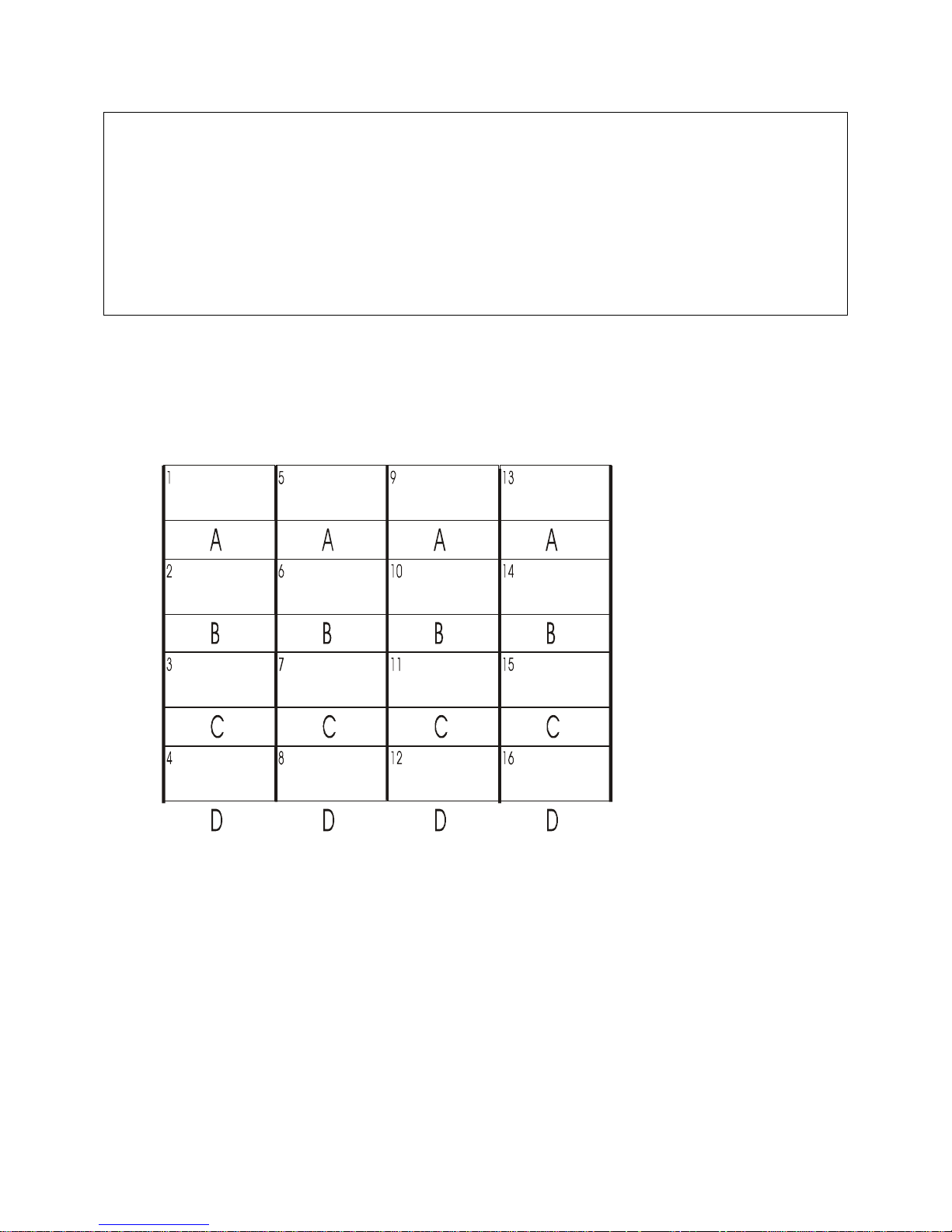
Fig. 4 Device Port Numbering
HELPFUL HINT: Make a diagram or spreadsheet of connections indicating connections
between devices and the ConsoleServer 3200 device ports as numbered above.
The Allow user to clear device buffer (Y/N) | YES > option determines
whether a user may use the CLEAR command to delete all the data stored in a device
port FIFO buffer. The sys admin may want to inhibit this ability to preserve user
accountability when accessing attached devices. Users are allowed to clear buffers by
default. Pressing <ENTER> will allow the user to clear the buffer; typing NO and then
pressing <ENTER> at the prompt when defining a user ID will disallow the user from
clearing all device buffers.
The Clear screen after a command (Y/N) | YES > option determines if the
screen clears when most commands are executed. Disallowing this screen behavior
keeps the last few commands and responses on the terminal screen. The default value
for this option is YES. Pressing <ENTER> will accept the default value; typing NO and
then pressing <ENTER> disallows this screen behavior.
5
A
6
B
7
C
8
D
9
A
10
B
11
C
12
D
13
A
14
B
15
C
16
D
17
A
18
B
19
C
20
D
21
A
22
B
23
C
24
D
25
A
26
B
27
C
28
D
29
A
30
B
31
C
32
D
23
Page 28

sys admin>>ADDUSER
Number of available user records: 200
Number of users defined: 0
Enter user id | USER ID > tom
Enter case sensitive password | PASSWORD > ****
Re-enter case sensitive password | PASSWORD > ****
0-17 | MAX CONCURRENT LOGINS: 1> 2
Allowed devices example: 1-5,10 | DEVICES 0 > 1-4
Allowed listen devices example: 1-5,10 | DEVICES 0 > 0
Allow user to clear device buffer (Y/N) | YES > n
Clear screen after a command (Y/N) | YES > n
Enter user id | USER ID >
Sys admin>>
The above procedure has defined one user. The ConsoleServer 3200 will prompt for
the next user ID to be defined. Repeat the set-up process until all users have been
entered. To return to the sys admin prompt, simply press <ENTER> at the USER ID>
prompt. More users may be added at any time by using the ADDUSER command. A
maximum of 200 users may be defined.
6.2.2 Editing a User ID
sys admin>>EDITUSER TOM
Enter accepts present value
Enter case sensitive password | PASSWORD >
0-17 | MAX CONCURRENT LOGINS: 2>6
Allowed devices example: 1-5,10 | DEVICES 1-4 >
Allowed listen devices example: 1-5,10 | DEVICES 0 >
Allow user to clear device buffer (Y/N) | YES > n
Clear screen after a command (Y/N) | NO > n
sys admin>>
To edit or change parameters for a particular user after defining that user ID, use the
EDITUSER command. For example, if the user 'Tom' needed to have more concurrent
login capabilities, the sys admin would type EDITUSER TOM on the command line. As
each line comes up, change the settings and press <ENTER>, or press <ENTER> to
accept the current setting.
NOTE: When editing any group of parameters, pressing the <ENTER> key will accept
the current value and move to the next parameter in the list.
6.2.3 Listing User IDs
To list the users that have been defined, use the LISTUSERS command. When used
alone, the command will display all user ID’s. When a user ID is specified after the
command, the parameters for that user ID will be displayed. If the /ALL qualifier is
included after the LISTUSERS command, then the parameters for all users are
displayed.
24
Page 29

sys admin>>LISTUSERS
1: User id > PETE
2: User id > KEVIN
3: User id > TONY
sys admin>>LISTUSERS /ALL
1: User id > PETE
Allowed devices > 1-32
Allowed listen devices > 1-32
Max logins > 17
Allow user to clear device buffer > YES
Clear screen after a command > YES
2: User id > KEVIN
Allowed devices > 1-32
Allowed listen devices > 1-32
Max logins > 17
Allow user to clear device buffer > YES
Clear screen after a command > YES
3: User id > TONY
Allowed devices > 1-32
Allowed devices > 1-32
Max logins > 17
Allow user to clear device buffer > YES
Clear screen after a command > YES
sys admin>>
6.2.4 Deleting a User ID
To delete a user, use the DELETEUSER command, followed by the user ID on the same
line. The LISTUSERS command will allow verification after deleting a user ID. The
following command sequence is an example of the use of DELETEUSER with
LISTUSERS:
sys admin>>DELETEUSER PETE
Delete user:pete Yes or No (N):y
sys admin>>listusers
2: User id > KEVIN
3: User id > TONY
sys admin>>
User IDs may also be deleted by their record number. As each user ID is created, it is
assigned a sequential record number. This number is associated with the user ID and
will be displayed using the LISTUSER command.
sys admin>> deleteuser /3
Delete user:tony Yes or No (N):y
sys admin>>
25
Page 30

To delete a user ID using the record number, specify the number as a qualifier after the
DELETEUSER command in the form DELETEUSER /N, where N is the user record
number.
6.3 Devices
Devices Command
DevicesDevices
Device port parameters must be defined by the sys admin using the DEVICES
command. If a single device port is to be changed, the port number must follow the
DEVICES command. If the DEVICES command is entered by itself, the configuration of
all device ports will be listed. To edit all possible device ports for a unit, enter the
command DEVICES /ALL.
Programmable elements include: device name, baud rate, stop bits, parity, data bits,
DCE/DTE, flow control and inhibit direct mode. Pressing <ENTER> accepts the
parameter as is. If changes need to be made, each parameter may be edited as it
comes up after each > prompt.
The device name may not contain the * character. If a name is entered with this
character, the administrator will be asked to re-enter the name.
Four baud rates are offered: 9600, 19200, 38400, and 57600. Most devices use 9600
as the console/admin port baud rate, so the device port defaults to this value. Check
the equipment documentation for the proper baud rate.
The format of the bit-wise transmission of data is determined by the stop bits, parity,
and data bits parameters. The default settings are 1 stop bit, no parity, and 8 data bits.
Check the equipment documentation for the proper settings.
Each device port may be separately configured as either DCE or DTE. The DCE setting
is used when connecting to a DTE device such as a computer. The DTE setting is used
when connecting to a DCE device such as a managed switch. The device ports are
configured as DCE by default.
The device port flow control setting determines the method of flow control. The two
most common settings are XON/XOFF (a.k.a. software) and RTS/CTS (a.k.a.
hardware). DTR/DSR is used very infrequently. The default setting for the device ports
is XON/XOFF. Check the equipment documentation for the correct flow control setting.
The INHIBIT DIRECT MODE setting allows the administrator to turn off port buffering
while a user is connected to the device and is in direct mode. The device port buffer still
collects data while not in direct mode when this setting is active. It may be desirable to
disable direct mode buffering so sensitive data is not viewable by other users, but alert
and panic messages from the attached device are still stored when nobody is
connected. This setting is disabled by default, so buffer data is collected both in and out
of direct mode.
26
Page 31

HIJ
N
O
sys admin>>terminal 1
Enter accepts present value
T1: 0=9600, 1=19200, 2=38400, 3=57600 | BAUD RATE: 9600>
T1: 0=1, 1=2 | STOP BITS: 1>
T1: 0=None, 1=Odd, 2=Even | PARITY: None>
T1: 0=8, 1=7, 2=6 | DATA BITS: 8>
T1: 0=DCE, 1=DTE | EQUIP PORT TYPE: DCE>
T1: 0=XON/OFF, 2=RTS/CTS | FLOW CONTROL: XON/XOFF>
Card installed, settings updated
sys admin>>
Device port location reference and device name template:
HI J KL MNO
A list of device port names and their corresponding port number may be displayed by
using the LISTDEVICES command.
6.4 Terminals
The sys admin defines terminal port parameters using the TERMINALS command in a
manner similar to the DEVICES command. If the command is entered by itself, the
terminal settings will display. If the terminal port number is specified after the
command, then the settings for that terminal port may be altered. Programmable
elements include: device name, baud rate, stop bits, parity, data bits, DCE/DTE, and
flow control as in the example below.
Terminals Command
TerminalsTerminals
KLM
27
Page 32
sys admin>>TERMINALS 1
Enter accepts present value
T1: 0=9600, 1=19200, 2=38400, 3=57600 | BAUD RATE: 38400>
T1: 0=1, 1=2 | STOP BITS: 1>
T1: 0=None, 1=Odd, 2=Even | PARITY: None>
T1: 0=8, 1=7, 2=6 | DATA BITS: 8>
T1: 0=DCE, 1=DTE | EQUIP PORT TYPE: DTE>
T1: 0=XON/OFF, 1=DTR/DSR, 2=RTS/CTS | FLOW CONTROL: XON/XOFF>
Card installed, settings updated
sys admin>>
Terminal port connection location reference template:
CBDE
6.5 Network
Network Command
NetworkNetwork
The NETWORK command will define a primary and secondary configuration for each card
slot. The primary configuration will define the network card’s IP address, local subnet
mask, and default gateway. The secondary configuration allows the sys admin to define
a routing path to reach a specific destination network via an alternate gateway that has
a better route to that destination network. The network administrator for the
ConsoleServer 3200 will determine if it is necessary to use this feature. If the
secondary configuration will not be used, all fields for the secondary configuration
should be set to 255.255.255.255 (which is the default setting).
28
Page 33

The NETWORK command will either display the network settings of the installed network
cards or change those settings depending on which command qualifier is used.
sys admin>>NETWORK
N-B: IP address | 000.000.000.000>
N-B: Subnet Mask | 255.255.255.255>
N-B: Enter Default Gateway address | 255.255.255.255>
N-B: Enter 2nd Dest. Network | 255.255.255.255>
N-B: Enter 2nd Netmask | 255.255.255.255>
N-B: Enter 2nd Gateway address | 255.255.255.255>
N-B: BOOTP at startup? | Y>
N-C: IP address | 000.000.000.000>
N-C: Subnet Mask | 255.255.255.255>
N-C: Enter Default Gateway address | 255.255.255.255>
N-C: Enter 2nd Dest. Network | 255.255.255.255>
N-C: Enter 2nd Netmask | 255.255.255.255>
N-C: Enter 2nd Gateway address | 255.255.255.255>
N-C: BOOTP at startup? | Y>
N-D: IP address | 000.000.000.000>
N-D: Subnet Mask | 255.255.255.255>
N-D: Enter Default Gateway address | 255.255.255.255>
N-D: Enter 2nd Dest. Network | 255.255.255.255>
N-D: Enter 2nd Netmask | 255.255.255.255>
N-D: Enter 2nd Gateway address | 255.255.255.255>
N-D: BOOTP at startup? | Y>
N-E: IP address | 000.000.000.000>
N-E: Subnet Mask | 255.255.255.255>
N-E: Enter Default Gateway address | 255.255.255.255>
N-E: Enter 2nd Dest. Network | 255.255.255.255>
N-E: Enter 2nd Netmask | 255.255.255.255>
N-E: Enter 2nd Gateway address | 255.255.255.255>
N-E: BOOTP at startup? | Y>
sys admin>>
When used without qualifiers, the NETWORK command will display the network settings
assigned to each card slot. The IP address, subnet mask, default gateway, secondary
route, and bootp settings are displayed for each slot. These parameters are assigned
to the slots rather than the cards. If a network card is moved from one slot to another, it
will have the parameters assigned to its new slot rather than those previously assigned
to it.
29
Page 34

sys admin>>NETWORK /ALL
Enter accepts present value
N-B: Enter IP address | 000.000.000.000>
N-B: Enter Subnet Mask | 255.255.255.255>
N-B: Enter Default Gateway address | 255.255.255.255>
N-B: Enter 2nd Dest. Network | 255.255.255.255>
N-B: Enter 2nd Netmask | 255.255.255.255>
N-B: Enter 2nd Gateway address | 255.255.255.255>
N-B: BOOTP at startup? | Y>
Save changes and update card? Yes or No: No>
N-C: Enter IP address | 000.000.000.000> 172.16.1.2
N-C: Enter Subnet Mask | 255.255.255.255> 255.255.255.0
N-C: Enter Default Gateway address | 255.255.255.255> 172.16.1.200
N-C: Enter 2nd Dest. Network | 255.255.255.255>
N-C: Enter 2nd Netmask | 255.255.255.255>
N-C: Enter 2nd Gateway address | 255.255.255.255>
N-C: BOOTP at startup? | Y>
Save changes and update card? Yes or No: No>y
Card installed, settings updated
N-D: Enter IP address | 000.000.000.000> 172.16.1.3
N-D: Enter Subnet Mask | 255.255.255.255> 255.255.255.0
N-D: Enter Default Gateway address | 255.255.255.255> 172.16.1.200
N-D: Enter 2nd Dest. Network | 255.255.255.255>
N-D: Enter 2nd Netmask | 255.255.255.255>
N-D: Enter 2nd Gateway address | 255.255.255.255>
N-D: BOOTP at startup? | Y>
Save changes and update card? Yes or No: No>y
Network card not installed in slot D
N-E: Enter IP address | 000.000.000.000> 172.16.1.4
N-E: Enter Subnet Mask | 255.255.255.255> 255.255.255.0
N-E: Enter Default Gateway address | 255.255.255.255> 172.16.1.200
N-E: Enter 2nd Dest. Network | 255.255.255.255>
N-E: Enter 2nd Netmask | 255.255.255.255>
N-E: Enter 2nd Gateway address | 255.255.255.255>
N-E: BOOTP at startup? | Y>
Save changes and update card? Yes or No: No>y
Network card not installed in slot E
sys admin>>
When used with the /ALL qualifier, the NETWORK command will allow the system
administrator to change the network parameters for all the card slots in order. The sys
admin will be prompted to enter the IP address, subnet mask, default gateway,
secondary route, and bootp settings for each card slot. If <ENTER> is pressed at the
prompt, the value displayed in the prompt will be used. After entering the parameters
for each slot, the sys admin will be asked if the new parameters should be used. If NO
is entered (or just <ENTER> is pressed), then the previously entered changes will be
discarded and the system will move on to the next slot’s parameters. If YES is entered,
then the slot’s network parameters will update in control card memory and the control
card will send the new parameters immediately to the card in that slot. If the card is a
network card, it will immediately acquire the new network parameters and disconnect all
telnet sessions to that card. If a terminal card is in the slot, or if the slot is empty, the
network parameter update is refused, but the network parameters for that slot will be
saved to control card memory.
30
Page 35

sys admin>>NETWORK B
Enter accepts present value
N-B: Enter IP address | 000.000.000.000> 172.16.1.1
N-B: Enter Subnet Mask | 255.255.255.255> 255.255.255.0
N-B: Enter Default Gateway address | 255.255.255.255> 172.16.1.200
N-B: Enter 2nd Dest. Network | 255.255.255.255>
N-B: Enter 2nd Netmask | 255.255.255.255>
N-B: Enter 2nd Gateway address | 255.255.255.255>
N-B: BOOTP at startup? | Y>
Save changes and update card? Yes or No: No>y
Card installed, settings updated
sys admin>>
When the NETWORK command is used with a card slot letter as a command qualifier, it
will attempt to change the parameters only for that card slot. In all other aspects, the
command behaves the same as if the /ALL qualifier was used.
If a bootp server is present on the same network as the ConsoleServer 3200 network
card and bootp is enabled on the network card, then the network card will use the IP
address and subnet mask assigned by the bootp server rather than those assigned by
the sys admin.
Once a network card has been assigned an IP address either by a bootp server or by
the sys admin, then the ConsoleServer may be accessed by telnet. Connecting to the
default telnet port reaches the user login; connecting to port 5000 reaches the sys
admin login.
6.6 Modem
Modem Command
ModemModem
The MODEM command allows manipulation of the modem card initialization string. When
the command is entered, the sys admin is prompted for the new initialization string.
Typing a new initialization string and pressing <ENTER> will create a new initialization
string for the modem, while just pressing <ENTER> will accept the current value. After
pressing <ENTER>, the sys admin is asked to confirm the changes to send the string to
the modem. Typing YES and <ENTER> will send the initialization string immediately to
the modem card, while typing NO and <ENTER> discards the entered initialization string
and keeps the old string. If the modem card is not currently installed, the settings are
not sent, but are kept in control card memory. The control card will send those settings
in memory when a modem card is installed.
31
Page 36

sys admin>>MODEM
Enter accepts present value
Init string | > ATB2H0
Save changes and update modem card? Yes or No: No>yes
Modem card not installed in slot A, init string saved
Sys admin>MODEM /DEFAULT
Current modem init string is: ATB2H0
Set modem to factory default value of: ATH0S0=1
(write out YES) Yes or No: No>yes
Modem card not installed in slot A, init string saved
sys admin>>
The sys admin may also reset the initialization string to the default value by entering the
command with the default qualifier in the form MODEM /DEFAULT. When using the
/DEFAULT qualifier, the current initialization string is displayed, along with the factory
default string. The sys admin is asked to confirm the use of the default modem string;
typing YES and <ENTER> will send the default initialization string immediately to the
modem card, while typing NO and <ENTER> keeps the old modem string.
It is recommended that the default modem initialization string be used unless the
application requires that it be changed. The default initialization string is ATH0S0=1,
which disconnects any active phone connections when the initialization string is sent,
and sets the modem to auto-answer on one ring.
6.7 Status Commands
There are six commands which allow the sys admin to check the status of the
ConsoleServer 3200: CONNECTIONS, LISTCARDS, VERSION, INFO, POWERSTATUS
and LOG.
6.7.1 CONNECTIONS
CONNECTIONS Command
CONNECTIONSCONNECTIONS
The sys admin may monitor the status of connections made through the terminal cards
by using the CONNECTIONS command. This command will display all the active
connections and the mode of those connections as follows:
32
Page 37

sys admin>>CONNECTIONS
Terminal Connection List
01 KEVIN 01 SERVER ( Monitor mode )
02 00 ( Channel present )
03 00 ( Channel present )
04 00 ( Channel present )
05 00 ( Channel present )
06 00 ( Channel present )
07 00 ( Channel present )
08 00 ( Channel present )
09 00 ( Channel present )
10 00 ( Channel present )
11 00 ( Channel present )
12 00 ( Channel present )
13 00 ( Channel present )
14 00 ( Channel present )
15 00 ( Channel present )
16 00 ( Channel present )
17 <not installed>
sys admin>>
The above example shows that user KEVIN is logged in on terminal port 01, is
connected to device port 01 (which is named "Server" in the ConsoleServer 3200), and
is in monitor mode. The list will display the user ID of any logged-in users, the device
port to which they are connected, the device name assigned to that port, and the mode
of that connection (see sections 7.8, 7.9, and 7.10 for an explanation of the various
connection modes). If the user is not connected to any device, they shall simply be
listed as "User Logged-In".
When used with the /MONITOR command line qualifier, the CONNECTIONS command
updates the connection list on screen every time a user logs in or out or changes login
level (i.e., goes into direct mode), rather than simply displaying the list once as occurs
when the CONNECTIONS command is used alone. (See section 6.8, Sys Admin Session
Management Commands).
The CONNECTIONS command will also tell the sys admin which terminal ports are
present (in the list, they are referred to as "channels"). If the port is not functioning (i.e.,
the card is not present or there is a fault with the individual port), the port will be listed
as "<not installed>". It will also list Telnet Active for an active Telnet session.
33
Page 38

6.7.2 LISTCARDS
Sys admin>>LISTCARDS
Installed cards
Slot A : <card not installed>
Slot B : Terminal card installed
Slot C : Terminal card installed
Slot D : Terminal card installed
Slot E : Terminal card installed
Slot F : Switch card 1 installed
Slot G : Switch card 2 installed
Slot H : Device card installed
Slot I : Device card installed
Slot J : Device card installed
Slot K : Device card installed
Slot L : Device card installed
Slot M : Device card installed
Slot N : Device card installed
Slot O : Device card installed
sys admin>>
LISTCARDS Command
LISTCARDSLISTCARDS
The LISTCARDS command will simply tell the sys admin which cards are plugged into
the ConsoleServer 3200 chassis. It only lists the cards (by type) as present or not
present, and does not indicate whether the cards are functioning properly.
6.7.3 VERSION
sys admin>>VERSION /ALL
ConsoleServer 3200
Slot B1: V2.15 10/01/99 Terminal Boot V1.62 (Sep 30 1999) (14:33:12)
Slot C1: V2.15n 10/01/99 Net Terminal Boot V1.62 (Sep 30 1999) (12:44:32)
Slot C2: V1.16 Build 7 09/29/99 Network Boot V1.62 (Sep 30 1999) (14:45:52)
Ethernet Address: 00-30-31-00-01-D5
Slot F1: V 1.03 Switch 1
Slot G1: V 1.03 Switch 2
Slot H1: V2.15 10/04/99 Device Boot V1.62 (Sep 30 1999) (14:40:51)
Slot P1: V2.12 Build 15 10/01/99 Control Boot V1.62 (Oct 01 1999) (11:13:06)
sys admin>>
VERSION Command
VERSIONVERSION
By itself, the VERSION command lists the boot and flash software version for the control
card. The version information for a single card other than the control card may be
displayed by typing the card slot letter ID after the VERSION command. If the sys admin
desires to list the software version for all cards, he should type VERSION /ALL at the
command prompt. This will list the versions of the boot and flash software for all cards,
listed by card slot letter designation. Each network card will display two sets of software
versions: one set for the network portion of the card and one for the user terminal
portion, while all other cards will only return one set of version information.
34
Page 39

6.7.4 INFO
sys admin>>INFO A
Slot A1: Modem: No Active Call Timeout = 1 mins.
Current Modem State: in command mode
Modem Init String: ATH0S0=1
Modem error: none
sys admin>INFO C
Slot C2: 0 Active Telnet Sessions Timeout = 1 mins.
Ethernet Address: 00-30-31-00-00-4F
IP=172.16.1.31 SM=255.255.255.0 GW=172.16.1.151
2nd route: IP=255.255.255.255 SM=255.255.255.255 GW=255.255.255.255
sys admin>>INFO D
Slot D1:
Port 9(A) DCE 38400,N,8,1 Flow=XON/XOFF RTS=0 DTR=1
Port 10(B) DCE 38400,N,8,1 Flow=XON/XOFF RTS=0 DTR=1
Port 11(c) DCE 38400,N,8,1 Flow=XON/XOFF RTS=0 DTR=1
Port 12(D) DCE 38400,N,8,1 Flow=XON/XOFF RTS=0 DTR=1
sys admin>>
INFO Command
INFOINFO
The INFO command allows the sys admin to list the properties of a card. The switch
cards are incapable of returning information, and any request to view information from
the switch cards will be refused.
The INFO command is used in the form INFO <slot letter>, where <slot
letter> is the letter designation of the card slot in the ConsoleServer 3200 chassis.
The modem card will always be in card slot A, while the network card may be in slots B,
C, D, or E.
The modem card will return the following information:
• The slot letter and processor number (which will always be "A1")
• The connection status of the modem
• The current modem session timeout limit (see Section 6.9,Breaking User
Connections)
• The current modem state, listed as either power-up mode or command mode
• The modem initialization string sent at startup
• Any miscellaneous modem error messages
The network card will return the following information:
• The slot letter and processor number (the number will always be “2”)
• The amount of active telnet sessions
• The telnet session timeout limit
• Sys Admin sessions
• The unique hardware (MAC) address of the card, expressed as six groups of one-
byte hexadecimal numbers
• IP source 3200, BootP, RARP
35
Page 40
• The primary IP information, including: IP address, subnet mask, and gateway
• The secondary IP information, including: destination address, subnet mask, and
gateway
The terminal and device cards will return the following information:
• The terminal or device port number
• The port letter as indicated on card label
• Equipment port type (DCE or DTE)
• Baud rate
• Parity; N=none, E=even, O=odd
• Data bits
• Stop bits
• Flow control type
• Status of RTS line; 0=off, 1=on
• Status of DTR line; 0=off, 1=on
The labels “RTS” and “DTR” do not change when the port type is changed from DCE to
DTE. When the port type is changed, the label “RTS” indicates the status of the CTS
line, and “DTR” indicates the status of the DSR line.
6.7.5 POWERSTATUS
sys admin>>POWERSTATUS
Power supply A is OK
Power supply B is OK
sys admin>>
POWERSTATUS Command
POWERSTATUSPOWERSTATUS
The POWERSTATUS command displays the status of the two redundant power supplies
in the ConsoleServer 3200 chassis. Power supplies will either be listed as OK or
Failed. The ConsoleServer 3200 will continue to function with one failed power
supply. Contact Lightwave for information regarding replacement if a power supply
fails.
6.7.6 LOG
sys admin>>log /enable
LOG Command
LOGLOG
The ConsoleServer 3200 can report current system activity through control card port B.
The report is enable using the command LOG /ENABLE, and disabled using the
command LOG /DISABLE.
The system will report user logins, logouts, device port selections, and entry/exit from
direct mode. Note that there is no system clock on the ConsoleServer 3200, so there is
36
Page 41

no time/date stamp on system activity. If a time/date stamp is required, it must be
provided by the system capturing the data output.
Connection instructions for the logging port:
1. Turn on power to the terminal or computer. If using a computer, start the desired
communication program. The terminal or communications program used must
be in VT100 emulation mode
2. Ensure that the communications settings are correct. The factory defaults for the
control card, which may only be changed by a hardware DIP switch, are 9600
baud, 8 data bits, 1 stop bit, and no parity (9600 8N1). If in doubt as to the
current communication settings on the control card, check the DIP switches and
refer to Figure 2, Control Card Layout with DIP Switch Settings, on page 9.
3. Locate the serial port on the terminal or computer and determine what type of
connector is used. The cable kit included with the ConsoleServer 3200 contains
each of the following: one RJ45 serial cable, an RJ45 to male DB9 adapter, an
RJ45 to female DB9 adapter, an RJ45 to male DB25 adapter, and an RJ45 to
female DB25 adapter. Select the appropriate adapter for the serial port on the
terminal or computer.
4. Firmly seat the adapter in the serial port. Screw down the adapter to secure it to
the serial port.
5. Insert one end of the serial cable into the adapter until a click is heard. Insert the
other end of the serial cable into port "B" of the control card, again until a click is
heard.
6. At the sys admin>> prompt, enter the command LOG /ENABLE. Log in as a
user as outlined in chapter 7. Check for output on the logging port. If no output
has appeared, check all cable connections. If “garbage” characters appear,
check that all communications parameters match.
7. The ConsoleServer 3200 will continue to output logging information through the
“B” port of the control card until the command LOG /DISABLE is entered at the
sys admin>> prompt. Configure any text captures or scripts as needed to
receive the logging data.
6.8 Sys Admin Session Management Commands
The ConsoleServer 3200 features two commands that allow the sys admin to manage
properties of the control port terminal session.
37
Page 42

6.8.1 LINESPERPAGE
sys admin>>LINESPERPAGE
Lines per page set to 22
sys admin>LINESPERPAGE 10
Lines per page set to 10
sys admin>>
LINESPERPAGE Command
LINESPERPAGELINESPERPAGE
The LINESPERPAGE command allows the sys admin to change the number of lines
displayed per terminal page on the control card port before the MORE prompt is
displayed. The number of lines to display per page is entered after the command.
Entering the command without a number following will display the current amount of
lines displayed per page. The default value is 22, which will work properly with a 24-line
display.
6.8.2 TIMEOUT
sys admin>>TIMEOUT
Timeout set to 1 minutes
sys admin>>TIMEOUT 0
Timeout set to 0 minutes
0 disables the timeout from occurring
sys admin>>TIMEOUT 5
Timeout set to 5 minutes
sys admin>>
TIMEOUT Command
TIMEOUTTIMEOUT
The TIMEOUT command allows the sys admin to define a time limit on how long an idle
sys admin terminal may remain logged in. If there is no interaction for the defined
amount of time, the control card will log out the sys admin. The time limit in minutes is
entered as a command qualifier after the command, and must be entered as a whole
number. Defining the time limit as 0 will disable this function. The default value is one
minute.
6.9 Breaking User Connections
The sys admin has four commands available to forcibly break user connections to
devices. The commands BREAK and FORCELOGOUT allow the sys admin to break any
connection on demand, while TELNETTIMEOUT and MODEMTIMEOUT automatically
break idle user sessions for the network or modem card.
6.9.1 BREAK
sys admin>>BREAK 1
Break this connection? (write out YES) Yes or No: No>yes
sys admin>>
BREAK Command
BREAKBREAK
38
Page 43
The BREAK command allows the sys admin to disconnect a user from the device port to
which they were connected if they are in monitor, listen, or direct mode. The user is still
logged in after the connection is broken, but there is no longer any connection between
the terminal port and the device port. The sys admin must specify the terminal port
number (as listed with the CONNECTIONS command) of the connection to be severed
when using the BREAK command. Pressing <ENTER> or typing NO at the confirmation
prompt will abort the command. To execute the command, enter YES at the
confirmation prompt.
6.9.2 FORCELOGOUT
sys admin>>FORCELOGOUT 1
Force this user off? (write out YES) Yes or No: No>yes
sys admin>>
FORCELOGOUT Command
FORCELOGOUTFORCELOGOUT
The FORCELOGOUT command causes the forcible logout of a user at any level of
connection. The user will be returned to the LCI3200> prompt after being forced off,
and may login again unless their allowed logins are reduced to 0 before they can
attempt another login. When using the FORCELOGOUT command, the sys admin must
specify the terminal port number (as listed with the CONNECTIONS command) of the
user to be forced off. Pressing <ENTER> or typing NO at the confirmation prompt will
abort the command. To execute the command, enter YES at the confirmation prompt.
sys admin>>FORCELOGOUT SYSADMIN B
Force logout sys admin? (write out YES) Yes or No: No>yes
sys admin>>
The FORCELOGOUT command may also be used to disconnect a network sys admin
session. The qualifiers SYSADMIN and the network card slot ID must be specified after
the command.
6.9.3 TELNETTIMEOUT
sys admin>>TELNETTIMEOUT
Timeout set to 5 minutes
Sys admin>>TELNETTIMEOUT 0
Timeout set to 0 minutes
0 disables the timeout from occurring
sys admin>>TELNETTIMEOUT 2
Timeout set to 2 minutes
sys admin>>
TELNETTIMEOUT Command
TELNETTIMEOUTTELNETTIMEOUT
39
Page 44

The TELNETTIMEOUT command allows the sys admin to define the amount of time that
a network card may have an idle telnet session before breaking the network connection.
A telnet session is considered to be idle if no characters are sent from the user’s
terminal. Once the time limit has been reached, the user will be logged out and the
network connection will be broken. The connection will be broken if there is no activity
at any login level (from logged out up to direct mode). This is intended to prevent a
“dead” session from tying up system resources. This command will define the idle time
limit for all network cards present in the chassis.
To display the current system value for the idle telnet session time limit, type
TELNETTIMEOUT at the command prompt. To change the time limit, the command is
entered in the form TELNETTIMEOUT <t>, where <t> is the time limit in whole minutes.
The valid range for <t> is 0 to 30, with the default value set as 1. If the value is set to
0, then the time limit is disabled.
6.9.4 MODEMTIMEOUT
Sys admin>>MODEMTIMEOUT
Timeout set to 5 minutes
Sys admin>>MODEMTIMEOUT 0
Timeout set to 0 minutes
0 disables the timeout from occurring
Sys admin>>MODEMTIMEOUT 2
Timeout set to 2 minutes
sys admin>>
MODEMTIMEOUT Command
MODEMTIMEOUTMODEMTIMEOUT
The MODEMTIMEOUT command is identical to the TELNETTIMEOUT command, but
causes the automatic disconnection of idle modem card sessions. The modem card will
deselect any currently selected device port channel, log the user out, and disconnect
the telephone connection once the idle session time limit has been reached. Entering
the time limit in whole minutes after the command sets the idle time limit. Entering a
value of 0 will disable the timeout. Entering the command by itself will display the
current modem idle call time limit.
Any users listening to a connection that is broken by BREAK, FORCELOGOUT,
TELNETTIMEOUT, or a MODEMTIMEOUT will lose the connection as well.
6.10 Saving and Restoring System Settings
The sys admin may save all the ConsoleServer 3200 system parameter settings
(terminal port settings, device port settings, user IDs, etc.) and restore them at a later
time using the BACKUP and RESTORE commands. To use this feature, the sys admin
must be directly connected to control card port 'A' using a terminal or communications
program capable of capturing the screen output from the ConsoleServer 3200 to a plain
ASCII file to backup the system settings, and then sending the file as plain ASCII text to
40
Page 45

the ConsoleServer 3200 to restore the system settings. It is not possible to use the
BACKUP and RESTORE commands from a network sys admin session.
Before beginning either the backup or restore processes, make sure that there are no
users logged in to the ConsoleServer 3200 by using the CONNECTIONS command. If
there are any users logged in, notify them to log out immediately or forcibly log them out
using the FORCELOGOUT command.
Once there are no users logged in, start the backup process by beginning the screen
output capture. Send the output to an ASCII file with a descriptive name (i.e.,
3200_backup.log). After the screen capture is set to run, begin sending the settings by
entering the command BACKUP at the sys admin>> prompt. The ConsoleServer 3200
will begin to output its internal records to the screen as ASCII characters in a code for
ConsoleServer 3200 internal use. The output may pause several times as the
ConsoleServer parses the records. Once all records have been sent to the screen, the
ConsoleServer 3200 will return to the sys admin>> prompt. Stop the screen capture
to close the ASCII file once the prompt returns to the screen.
Do not attempt to modify or edit the text in the captured ASCII file; modifying the
contents of the backup file will render the backup records invalid and unusable.
The last system records saved may be restored to the ConsoleServer 3200 using the
RESTORE command. As with the BACKUP command, all users must be logged out
before proceeding with the RESTORE process. To begin, enter the command RESTORE
at the sys admin>> prompt. The ConsoleServer will wait for the plain ASCII file
containing the system records (previously saved using the BACKUP command). Send
the records file to the ConsoleServer 3200 using the communications program's ASCII
file upload function. The ConsoleServer will exit the restore process and return to the
sys admin>> prompt without altering the current system records if the wrong file is
sent or if the file is somehow corrupted (i.e., through accident or attempted
modification). The 3200 does not provide any feedback of the data being restored and
since some Terminal Emulation Software i.e. Hypecterminal does not provide any
indication of an ACSI upload, i.e. Dialog Status Box, no indication will display until the
ConsoleServer completes the restore process. Once the records file has been
transmitted to the ConsoleServer and the restore process is complete, the
ConsoleServer 3200 will reboot and load the restored system settings.
6.11 Changing the System Prompt
The administrator may change the logged out system prompt for the ConsoleServer
3200. The prompt may not contain the “*” character, and can be up to 20 characters.
To change the system prompt, use the command PROMPT. Enter the new system
prompt when indicated and press <ENTER>.
41
Page 46

To change the system prompt to the default (LCI3200>), use the command PROMPT
/DEFAULT.
6.12 Updating the ConsoleServer 3200 Software
As new features are added to the ConsoleServer 3200, new versions of the system
software will become available. The sys admin may enter the ConsoleServer 3200
update mode using the command LCIUPDATE (which may never be abbreviated). It is
not necessary to backup the ConsoleServer 3200 system settings using the BACKUP
command before performing the software update, as all settings remain the same when
the update is complete. Appendix B covers the procedure for using the LCIUPDATE
command. The newest version of flash software is always available at the Lightwave
Communication’s FTP site (ftp://ftp.lightwavecom.com) accessible from any web
browser or FTP client.
42
Page 47

7.0 User Access and Interface
7.1 Terminal Card
Each terminal card has four (4) RJ45 connector ports to which a terminal may be
attached, giving a maximum of 16 physically connected terminals per ConsoleServer
3200 unit. The terminal card may be installed in slots B, C, D, or E.
To access servers through the ConsoleServer 3200 terminal card, the user must have
at least a text terminal capable of serial communication, a serial cable terminating in an
RJ45 connector, and the proper serial communication settings as determined by the
system administrator. The default communication settings are 38400, N, 8, or 1.
Once the hardware is properly connected and configured, the user may issue
commands to the terminal card. Before entering any commands, the user should be
sure that the terminal card is ready to accept commands by checking that there is a
prompt on screen. This is best accomplished by pressing <ENTER> until a prompt
appears on the screen (a prompt will not appear on the screen if the terminal port is in
direct mode, or if the serial cable is not connected properly).
7.2 Network Card
The network card must be connected to a network that uses TCP/IP. Devices
connected to the network card must be at 10 Mbits, half duplex, and no auto-negotiation
on 10-base T (Cat 5) wiring. The network card may be installed in slots B, C, D, or E.
Network settings are entered via the Sys Admin port.
To connect to the ConsoleServer 3200 network card, the user should use a TCP/IP
telnet client to telnet to the IP address assigned to the network card.
OCTANE_65 10# TELNET 172.16.1.31
Trying 172.16.1.31...
Connected to 172.16.1.31
Escape character is ‘^]’.
Welcome to the ConsoleServer 3200
You are connected to Port 5 via 172.16.1.31
LCI3200>
The user interface for the network card is exactly the same as that for the terminal card,
with a few minor exceptions. When a user first connects to the network card, the card
will display Welcome to the Console Server 3200, the ConsoleServer 3200
terminal port number for the connection, and the IP address of the network card. Once
at the LCI3200> prompt, the user interface behaves exactly the same as for the
terminal cards.
43
Page 48

At power-up, the network card does not respond to network connect requests until the
control card has completed its system initialization. Once the power-up sequence is
complete, the network card obtains its network parameters from the control card, and is
ready to accept connections over the network. It is important to note that the network
card does not retain its network parameters (i.e., IP address, subnet mask, gateway
address) if moved from one card slot to another. The network parameters remain
assigned to a card slot, and will be assigned to whatever network card is in that slot.
7.3 Modem Card
The modem card allows users to remotely access the servers attached to the
ConsoleServer 3200 via a dial-up connection. The modem automatically detects the
connection speed, and allows connections of up to 38.4K baud. The control card must
complete its start-up initialization check before a user may access the ConsoleServer
3200 through the modem card.
The modem card must be installed in card slot "A" of the ConsoleServer 3200 chassis.
The modem card will not function if it is inserted in any other card slot, nor will any other
card type function in slot A. To connect the modem card to the telephone network,
insert an ordinary telephone cable (RJ11) in the jack on the modem card, and insert the
other end in a telephone network jack, as outlined in section 5.3. See section 6.6 for
instructions on setting the modem initialization string.
The user interface for the modem card is identical to that found on the terminal card with
the exception of one command, which is outlined below. Only one user at a time may
connect to the modem card.
7.3.1 The B
Bye
ye Command
BB
yeye
A user may disconnect from the modem card and automatically log out from the
ConsoleServer 3200 by sending the BYE command. This command will work at any
login level that the user may send commands to the ConsoleServer 3200 (i.e., logged
out, logged in, and monitor mode). When the command is received, the modem card
disconnects the telephone connection, and then logs the user out from the
ConsoleServer 3200. This command is unique to the modem card user interface.
7.4 Overview of Commands
Several levels of access are available to the user, from simple access of the
ConsoleServer 3200 to direct access of servers attached to the ConsoleServer 3200.
Many of the commands are sensitive to which level the user is in, and not all commands
are available at all levels.
The first prompt the user should see after connecting to the ConsoleServer 3200 is the
LCI3200> prompt (additional information may be on the screen as indicated in the
44
Page 49

sections above). This indicates that the user is not currently logged in and that no
servers may be reached through the ConsoleServer 3200. The prompt will change to
reflect the level in which the user is, and in monitor mode, will also indicate which server
is selected.
The help screens also change according to the user's login level. There are separate
help screens for a logged out user, a logged in user, and a user in monitor (a.k.a.
device) mode.
LOGGED OUT HELP:
F1 - Display Help Screen (VT100 mode)
F2 - Display Pull Down Menu (VT100 mode)
TTY COMMANDS:(LOGGED OUT MODE)
LOGIN - Login with ID and Password
INFO - Display System Info
LOGGED IN HELP:
F1 - Display Help Screen (VT100 mode)
F2 - Display Pull Down Menu (VT100 mode)
TTY COMMANDS: (LOGGED IN MODE)
LOGOUT,LOGOFF - Logout
SELECT [SERVER NAME\#] - Select a server by name or number
LISTEN [SERVER NAME\#] - Listen to a server by name or number
DISELECT[SERVER NAME\#] - Select a server and enter direct mode
CHANGEPSWD or PASSWD - Change user password
CONNECTIONS - Display connections list
DEVLIST - Display installed devices list
EDITESC - Edit direct mode escape sequence
EDITBRK - Edit Break generation escape sequence
45
Page 50

MONITOR (A.K.A. DEVICE) MODE HELP:
F1 - Display Help Screen (VT100 mode)
F2 - Display Pull Down Menu (VT100 mode)
TTY COMMANDS: (MONITOR MODE)
LOGOUT,LOGOFF - Logout
SELECT [SERVER NAME\#] - Select a server by name or number
LISTEN [SERVER NAME\#] - Listen to a server by name or number
DISELECT[SERVER NAME\#] - Select a server and enter direct mode
EXIT - Deselect from a server
DEVLIST - Display installed devices list
TOP - Go to begining of device buffer
BOTTOM - Go to end of device buffer
NEXT - Display next page of device data
PREVIOUS - Display previous page of device data
FORWARD [n LINES] - Go forward n lines and display page
REVERSE [n LINES] - Go reverse n lines and display page
CAT - Display entire contents of device buffer
CAFILTER - Display entire contents of device buffer with
filter
CLEAR - Clear device buffer
DIRECT - Enter direct mode
The user may see a complete list of available commands at any prompt by typing HELP,
H, or ? and pressing <ENTER>, by pressing <F1>, or by selecting DISPLAY HELP
SCREEN from a pull-down menu. To use the pull-down menu of commands available at
each user level, the user may press <F2> or <CTRL>+D. By using the up and down
arrow keys, the user may move the highlight bar to the desired command, and then
press <ENTER> to select that command. The user may use the <F1> and <F2> keys
only if the terminal or terminal emulation supports VT100 function keys. If the terminal
or emulation program does not support VT100 function keys, then the user may press
the <CTRL> and D key simultaneously to use the pull-down menu. To exit from a menu
without selecting a command, press <ESC><ESC> or <CTRL>+C.
Pressing <CTRL>+U (the control and U key simultaneously) will erase all typed
commands on the current command line back to the system prompt. Pressing
<CTRL>+R retypes the last command executed and waits for the user to hit <ENTER> to
execute it.
Use <CTRL>+F for the down arrow and <CTRL>+E for the up arrow.
Most commands may be abbreviated to one extent or another. See Appendix E for
allowed abbreviations.
46
Page 51
7.5 Logging In and Changing Passwords
F2 PULL-DOWN MENU SHOWING INITIAL MENU CHOICES
┌─────────────────┐
│ LOGGED OUT MENU │
├─────────────────┤
│ USER LOG IN │
│ SYSTEM INFO │
│ DISPLAY HELP │
└─────────────────┘
To login, the user must type LOGIN at the LOGGED OUT> prompt or select USER LOG
IN from the pull-down menu. The user ID may also be entered as a command qualifier
after the login command.
LOGGED OUT>LOGIN
Please Enter User ID user_ID
Please Enter Password ****
- OR -
LOGGED OUT>login user_ID
Please Enter Password ****
If using the pull-down menu or if no user ID was entered as a qualifier, the
ConsoleServer 3200 will the prompt the user for their user ID by displaying Please
Enter User ID. At this prompt, they should type the user ID assigned to them by the
system administrator. After the user has entered their ID, they will be prompted for their
password when the ConsoleServer 3200 displays Please Enter Password. On the
first login, this will be a password assigned by the system administrator. The password
is case sensitive, so the user must be sure to type the password exactly as it is in the
system. The ConsoleServer 3200 will only echo stars for each character typed at the
password prompt. Once the user has entered their password, the screen will clear, and
a prompt displaying their user ID will appear, indicating that the ConsoleServer 3200 is
ready for use. For example, a user with an ID of "GEORGE" will have a prompt of
GEORGE> once they have logged in.
When a user profile is created by the sys admin, the password is pre-expired.
The user must change the password assigned by the sys admin before selecting
a device or listening to a device port for the first time.
To change the password, the user must use the command CHANGEPSWD or PASSWD.
The ConsoleServer 3200 will first prompt the user for the old password by displaying
PLEASE ENTER OLD PASSWORD. At this prompt, the user should enter the old
47
Page 52

password and press <ENTER>. The ConsoleServer 3200 will then prompt the user for
the new password by displaying the prompt PLEASE ENTER NEW PASSWORD. The
user should enter the new password (which may be up to ten alphanumeric characters
and is case-sensitive) at this prompt and press <ENTER>. After entering the new
password, the user will be asked to verify the new password by the prompt PLEASE
VERIFY PASSWORD. The user should enter the new password again at this prompt
exactly as it was typed the first time and press <ENTER>. If both new password entries
match, the ConsoleServer 3200 will display New password accepted. on the screen
and return to the user prompt. If the new entries do not match, the message New and
verify password mismatch is displayed, the new password is rejected, and the old
password remains valid. The ConsoleServer 3200 will also reject a new password if the
incorrect password is entered when prompted for the old password, or if the new
password is the same as the old password.
7.6 Logging Out
A user may logout at any time that commands may be made to the ConsoleServer 3200
by typing LOGOUT, LOGOFF, or by selecting LOGOUT from a pull-down menu. When a
user is connected to a server and they logout, the connection to that server will be
broken and any other users that are listening to that session will lose their connection to
that server as well.
7.7 Checking Connections
CONNECTION INFO SCREEN
┌───────────────────────────────────────────────────────────────────────────┐
│ CONNECTION INFO │
├───────────────────────────────────────────────────────────────────────────┤
│01 - TEST 00 - User logged-in │
│02 - 00 - Channel present │
│03 - 00 - Channel present │
│04 - 00 - Channel present │
│05 - 00 - Channel present │
│06 - 00 - Channel present │
│07 - 00 - Channel present │
│08 - 00 - Channel present │
│09 - 00 - │
│10 - 00 - │
│11 - 00 - │
│12 - 00 - │
│13 - 00 - │
│14 - 00 - │
│15 - 00 - │
│16 - 00 - │
│17 - 00 - │
└───────────────────────────────────────────────────────────────────────────┘
Press Any Key To Continue ....
Only one user at a time may connect to a device on the ConsoleServer 3200, except
when using listen mode (see Section 7.9, Listening to a Server Session for more
details). Before attempting to select a device port, the user may desire to check if the
device port is free. The CONNECTIONS command allows the user to list the users that
48
Page 53

are logged in, which devices they have currently selected, and which mode they are in.
Users may also view this information by selecting DISPLAY CONNECTED LIST from
the pull-down menu when logged in.
7.8 Selecting a Device Port
F2 PULL-DOWN MENU TO SELECT A DEVICE PORT, PART 1
┌──────────────────────────┐
│ LOGGED IN MENU │
├──────────────────────────┤
│ CONNECT TO SERVER │
│ DIR CONNECT TO SERVER │
│ LISTEN TO SERVER │
│ DISPLAY CONNECTED LIST │
│ DISPLAY SERVER NAMES │
│ DISPLAY ACTIVE DEVICES │
│ LOGOUT │
│ CHANGE PASSWORD │
│ CHANGE DIRECT MODE ESC │
│ CHANGE BREAK MODE ESC │
│ DISPLAY HELP │
└──────────────────────────┘
F2 PULL-DOWN MENU TO SELECT A DEVICE PORT, PART 2
┌───────────────────────────────────────────────────┐
│ SELECT SERVER │
├───────────────────────────────────────────────────┤
│01 – DEVICE_1 02 - DEVICE_2 │
│03 - DEVICE_3 04 - DEVICE_4 │
│05 - 06 - │
│07 - 08 - │
│09 - 10 - │
│11 - 12 - │
│13 - 14 - │
│15 - 16 - │
│17 - 18 - │
│19 - 20 - │
│21 - 22 - │
│23 - 24 - │
│25 - 26 - │
│27 - 28 - │
│29 - 30 - │
│31 - 32 - │
└───────────────────────────────────────────────────┘
To select a device port, the user must type SELECT along with a device port name or
number, or select CONNECT TO SERVER from the pull down menu, and then select the
device port to be connected. The user must also have permission to connect to a device
port as defined by the system administrator in their user profile. For example, to
connect to a server named Alpha on device port 23, the user may either type SELECT
Alpha, SELECT 23, or select CONNECT TO SERVER and then select Alpha from the
next menu that appears. If the system administrator has determined that the user does
49
Page 54

not have permission to access a server, the ConsoleServer 3200 will display the
message NO ACCESS TO DEVICE CHANNEL, and the connection will not be made.
The user may exit from their current device port first by using the EXIT command or
selecting EXIT FROM SERVER from the pull-down menu to free the device port for use
by other users. A user may not select a server that is already selected by another user.
When a server has been selected, the prompt will change to show which server has
been selected by displaying the user ID, a dash, and then the server name in the
general form USER_NAME-SERVER_NAME>. For example, if the user GEORGE selects
Alpha, the prompt would read GEORGE-Alpha>.
When this prompt is displayed, the user is in monitor mode. There is no direct
communication between the user and the server. Any output from the server is saved
to a buffer that may be accessed by the user (see Section 7.11, Using the Buffer), but
the user may issue no commands to the server. If the user desires to issue commands
to the server, they must enter direct mode (see Section 7.10, Direct Mode).
Note that when selecting a server from a pull-down menu, only those device ports that
are installed shall be displayed.
7.9 Listening to a Server Session
F2 PULL-DOWN MENU TO LISTEN TO A DEVICE PORT PART 1
┌──────────────────────────┐
│ LOGGED IN MENU │
├──────────────────────────┤
│ CONNECT TO SERVER │
│ DIR CONNECT TO SERVER │
│ LISTEN TO SERVER │
│ DISPLAY CONNECTED LIST │
│ DISPLAY SERVER NAMES │
│ DISPLAY ACTIVE DEVICES │
│ LOGOUT │
│ CHANGE PASSWORD │
│ CHANGE DIRECT MODE ESC │
│ CHANGE BREAK MODE ESC │
│ DISPLAY HELP │
└──────────────────────────┘
50
Page 55

F2 PULL-DOWN MENU TO LISTEN TO A DEVICE PORT PART 2
┌───────────────────────────────────────────────────┐
│ SELECT SERVER │
├───────────────────────────────────────────────────┤
│01 – DEVICE_1 02 - DEVICE_2 │
│03 - DEVICE_3 04 - DEVICE_4 │
│05 - 06 - │
│07 - 08 - │
│09 - 10 - │
│11 - 12 - │
│13 - 14 - │
│15 - 16 - │
│17 - 18 - │
│19 - 20 - │
│21 - 22 - │
│23 - 24 - │
│25 - 26 - │
│27 - 28 - │
│29 - 30 - │
│31 - 32 - │
└───────────────────────────────────────────────────┘
To monitor another user's server session, the user must type LISTEN followed by the
device port name or number, or select LISTEN TO SERVER and a device port from the
pull-down menu. There must be a connection between a user and a device port for
another user to be able to listen to the connection. Also, the user must have permission
to listen to the server as defined by the system administrator in their user profile. Any
user that can log in and has listen permission for a device port may listen to a session
on that device port. If the user does not have permission to listen to a server, the
ConsoleServer 3200 will display the message NO ACCESS TO DEVICE CHANNEL.
When listen mode is entered, the screen will clear, and the message LISTEN MODE,
PRESS ANY KEY TO EXIT.... will appear. To exit listen mode the user may press
any key. The user will also exit listen mode if the connection between the other
(interactive) user and the device port is broken.
Note that when selecting a server from a pull-down menu, only those device ports that
are installed shall be displayed.
51
Page 56

7.10 Direct Mode
F2 PULL-DOWN MENU SHOWING DEVICE (A.K.A. MONITOR) MODE OPTIONS
┌─────────────────────────┐
│ DEVICE MODE MENU │
├─────────────────────────┤
│ ENTER DIRECT MODE │
│ CONNECT TO SERVER │
│ DIR CONNECT TO SERVER │
│ DISPLAY NEXT PAGE │
│ DISPLAY PREVIOUS PAGE │
│ GOTO BEGINING OF BUFFER │
│ GOTO END OF BUFFER │
│ CLEAR BUFFER │
│ FORWARD N LINES │
│ REVERSE N LINES │
│ CAT │
│ CAT WITH FILTER │
│ EXIT FROM SERVER │
│ DISPLAY CONNECTED LIST │
│ LOGOUT │
│ DISPLAY HELP │
└─────────────────────────┘
If a user desires to interact directly with a server rather than only monitor its output, then
they must enter direct mode. To enter direct mode using the DIRECT command, the
user must first select a device port as outlined in Section 7.8, Selecting a Server. Then
at the prompt, the user must use the command DIRECT or select the command ENTER
DIRECT MODE from the pull-down menu. The user may also select a device port and
enter direct mode in one step by using the DISELECT command or selecting DIR
CONNECT TO SERVER from the pull-down menu. The DISELECT command must have
either the device port number or the name assigned to the port as the command
qualifier; if using the pull-down menu, a prompt box will appear to select the device port.
The user's terminal will then be directly connected to the server, and will act as if the
terminal was physically connected to the server. The ConsoleServer 3200 displays the
last page of the device buffer along with a system information message indicating which
device port is selected as the user enters direct mode.
7.10.1 Direct Mode Escape Sequence
To escape from direct mode, the direct mode escape sequence must be used. The
direct mode escape sequence is a series of two to five characters that allow the user to
leave direct mode and return to monitor mode. The factory default for the direct mode
escape sequence is <ESC> A (escape key, then uppercase "a"), but the user may
change the sequence by using the command EDITESC or selecting CHANGE DIRECT
MODE ESC from the pull-down menu at the user prompt. It is recommended that the
user only change the escape sequence if it causes problems with the hardware or
52
Page 57

software used. It is also recommended that the user avoid combinations of the <CTRL>
key and other keys, as these combinations are usually reserved for sending and
receiving special characters through the terminal. When the user changes the escape
sequence, a window with the hexadecimal representation of the old escape sequence
will appear. Pressing <ESC> to exit from the edit prompt will not work; it will add
additional <ESC> characters (hexadecimal value 1B) to the direct mode escape
sequence. If the user wishes to keep the old sequence, they need only to press
<ENTER>. Otherwise, they should press backspace to delete the old characters, then
enter the new sequence and press <ENTER>. If for some reason the selection is
unacceptable, an error message will appear and the sequence will revert to the old
character values. The escape sequence is stored with the user profile, therefore it is
possible to have different sequences for different users. A hardcoded escape sequence
is provided in the event that the programmed sequence is lost. It is semi-colon,
exclamation, semi-colon, exclamation or ‘;!;!’ none of these characters should echo
and no <ENTER> is required.
Appendix F lists the hexadecimal codes for the ASCII character set.
7.11 Using the Buffer
F2 PULL-DOWN MENU FOR DEVICE (A.K.A. MONITOR) MODE
┌─────────────────────────┐
│ DEVICE MODE MENU │
├─────────────────────────┤
│ ENTER DIRECT MODE │
│ CONNECT TO SERVER │
│ DIR CONNECT TO SERVER │
│ DISPLAY NEXT PAGE │
│ DISPLAY PREVIOUS PAGE │
│ GOTO BEGINING OF BUFFER │
│ GOTO END OF BUFFER │
│ CLEAR BUFFER │
│ FORWARD N LINES │
│ REVERSE N LINES │
│ CAT │
│ CAT WITH FILTER │
│ EXIT FROM SERVER │
│ DISPLAY CONNECTED LIST │
│ LOGOUT │
│ DISPLAY HELP │
└─────────────────────────┘
Each device port saves the output of a server to a FIFO buffer. Each buffer can store
up to 64K of data, giving approximately 100 text pages. However, the actual amount of
pages may vary according to the data. The user must be in monitor mode to view or
clear the data stored in the buffer.
user-DEVICE_1>TOP
53
Page 58

When at the monitor mode prompt, the user may view the contents of the buffer using
the commands TOP, BOTTOM, NEXT, PREVIOUS, FORWARD, and REVERSE, or by
selecting the commands DISPLAY NEXT PAGE, DISPLAY PREVIOUS PAGE, GOTO
BEGINNING OF BUFFER, GOTO END OF BUFFER, FORWARD N LINES, and
REVERSE N LINES from the pull down menu. The monitor mode prompt will appear at
the bottom of the displayed buffer data, and the user may enter commands normally at
this prompt. The prompt is prefixed with the position of the currently displayed screen in
the buffer; the top of the buffer is indicated by TOP>, the bottom of the buffer is indicated
as BOTTOM>, and any other position is indicated as a percentage of the total buffer
(e.g., 51%>).
Connecting...
W.O.P.R.
LOGIN:GUEST
PASSWORD:*****
LOGIN FAILED
LOGIN:SFALKEN
PASSWORD:********
LOGIN FAILED
LOGIN:JOSHUA
Greetings Professor Falken
How are you today?
>
TOP>usr1-DEVICE_1>
The following table outlines the functions of the individual commands and pull down
menu items.
COMMAND MENU ITEM FUNCTION
TOP
GOTO BEGINNING OF BUFFER displays first 24 lines of
buffer data
BOTTOM
GOTO END OF BUFFER displays last 24 lines of
buffer data
NEXT
DISPLAY NEXT PAGE displays next 24 lines of
buffer data
PREVIOUS
DISPLAY PREVIOUS PAGE displays previous 24
lines of buffer data
54
Page 59

FORWARD
FORWARD N LINES skip forward N lines in
buffer
REVERSE
REVERSE N LINES skip back N lines in
buffer
The commands FORWARD and REVERSE must be followed by the number of lines the
user wants to move in the buffer. The command will not execute if the number of lines
is omitted.
The user may also clear the buffer by using the command CLEAR or by selecting CLEAR
BUFFER from the pull-down menu. All data stored in the device buffer will be erased
and is not recoverable. The sys admin may inhibit this ability on a per-user basis by
either creating the user ID without this ability or editing the user parameters after the
user is created.
The CAT and CAT WITH FILTER commands allow a user to output the content of the
device buffer to the screen. This allows a user to capture the contents of a device buffer
by using the telnet client/terminal emulation software’s texr capture capabilities.
CAT outputs the data in the buffer exactly as it was received without any additional
formatting.
CAF outputs the data in the buffer by applying the same formatting that is used by the
TOP, BOTTOM, NEXT, and PREVIOUS type commands. Characters are counted and a
<CR><LF> is added after 80 characters if one is not found in the data. Due to the
counting, escape sequences may not be preserved. Tabs are considered one character.
55
Page 60

8.0 The Break Generation Sequence
F2 PULL-DOWN MENU TO CHANGE BREAK SEQUENCE
┌──────────────────────────┐
│ LOGGED IN MENU │
├──────────────────────────┤
│ CONNECT TO SERVER │
│ DIR CONNECT TO SERVER │
│ LISTEN TO SERVER │
│ DISPLAY CONNECTED LIST │
│ DISPLAY SERVER NAMES │
│ DISPLAY ACTIVE DEVICES │
│ LOGOUT │
│ CHANGE PASSWORD │
│ CHANGE DIRECT MODE ESC │
│ CHANGE BREAK MODE ESC │
│ DISPLAY HELP │
└──────────────────────────┘
The user may find it necessary to send a break to the selected server. The break
generation sequence is a two to five character sequence. The factory default break
generation sequence is <ESC> B (the escape key, then uppercase "b").
The user may edit the break generation sequence in a manner similar to the direct
mode escape sequence. The user may use the command EDITBRK or select CHANGE
BREAK MODE ESC from the pull-down menu. It is recommended that the user only
change the break generation sequence if it causes problems with the hardware or
software used. It is also recommended that the user avoid combinations of the <CTRL>
key and other keys, as these combinations are usually reserved for sending and
receiving special characters through the terminal. When the user changes the break
generation sequence, a window with the hexadecimal numerical equivalent of the old
break generation sequence will appear. Pressing <ESC> to exit from the edit prompt
will not work; it will add additional <ESC> characters (hexadecimal value 1B) to the
break generation sequence. If the user wishes to keep the old sequence, they need
only to press <ENTER>. Otherwise, they should press backspace or delete to remove
the old characters, then type the new sequence and press <ENTER>. If for some
reason the selection is unacceptable, an error message will appear and the sequence
will revert to the old character values.
Appendix F lists the hexadecimal codes for the ASCII character set.
56
Page 61

9.0 Displaying System Information
F2 PULL-DOWN MENU TO DISPLAY SYSTEM INFO
┌─────────────────┐
│ LOGGED OUT MENU │
├─────────────────┤
│ USER LOG IN │
│ SYSTEM INFO │
│ DISPLAY HELP │
└─────────────────┘
The user access cards are capable of displaying information about their software and
communications settings. This information can be accessed only at the LCI3200>
prompt by selecting SYSTEM INFO from the pull-down menu, or typing the command
INFO or MISC at the prompt.
The command line INFO/MISC commands are also available at the user prompt
USER>.
┌───────────────────────────────┐
│ MISC. SYSTEM INFO │
├───────────────────────────────┤
│V2.15 10/01/99 │
│TERMINAL SOFTWARE │
│Card Number\Channel = B1 │
│38,400 Baud │
│No Parity │
│8 Data Bits │
│1 Stop Bit │
│Software Flow Control │
│Port Type = DCE │
└───────────────────────────────┘
Press Any Key To Continue ....
The system information appears in a pop-up window. The first two lines show the
version of the software in flash memory and the type of software. The third line shows
the position of the terminal or network card in the ConsoleServer 3200 chassis. The
next six lines show the current communication settings for the port. Pressing any key
that sends a character through the terminal exits the window.
57
Page 62
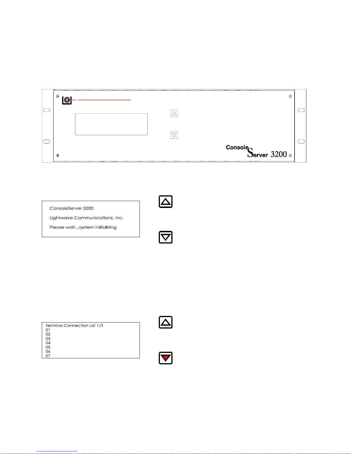
10.0 Front Panel Display Information:
The up/down arrow keys are used to scroll through multi-page displays.
Lightwave Communications, Inc.
The LCD displays the panel below at power up time. This will be displayed for as long
as five minutes while the ConsoleServer 3200 is in the initialize mode.
After the ConsoleServer 3200 has gone through the initialization phase, the terminal
connection list will automatically be displayed. To display the next panel in a function,
press the down arrow on the ConsoleServer 3200. To display the previous panel, press
the up arrow.
Panel 2 (press down)
58
Page 63

Panel 3 (press down)
Panel 4 (press down)
The next series of panel shows the port number along with the name of the device
connected to that port.
Panel 5 (press down)
Panel 6 (press down)
59
Page 64
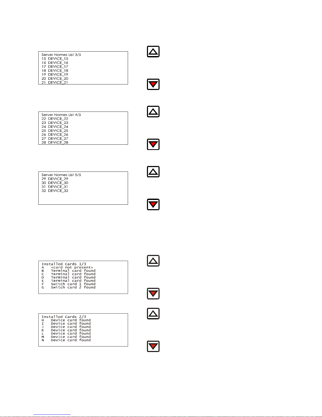
Panel 7 (press down)
Panel 8 (press down)
Panel 9 (press down)
The next series of panels displays the inventory of cards that are installed in the
chassis.
Panel 10 (press down)
Panel 11 (press down)
60
Page 65

Panel 12 (press down)
The last panel displays the status of the power supplies.
Panel 13 (press down)
61
Page 66
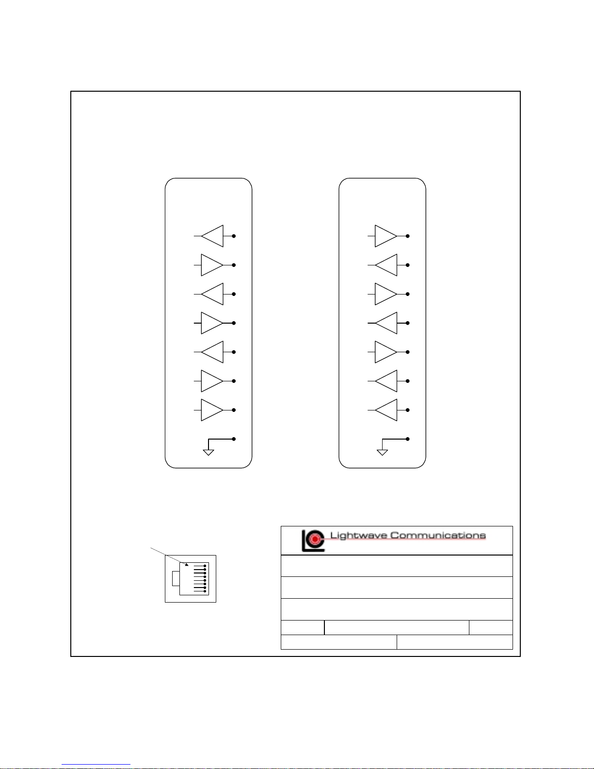
Appendix A – Adapter & Connector Pinouts
ConsoleServer 3200
Terminal / Device
(DCE)
Tx
Rx
RTS
CTS
DTR
DSR
DCD
SG
ConsoleServer 3200
Terminal / Device
RJ45
3
2
7
8
4
6
1
5
(DTE)
Tx
Rx
RTS
CTS
DTR
DSR
DCD
SG
RJ45
3
2
7
8
4
6
1
5
pin 1
RJ-45 Connector
100 Washington Street, Milford CT 06460
800 871-9838 * Fax 203 874-0157 * www.lightwavecom.com
Title:
Part Number
Drawing Number
Size:
Terminal / Device RJ45 Connector Pinouts
System:
AA
3200_term_dev.vsd
ConsoleServer 3200
SheetFile:
Rev:
of
0101
62
Page 67
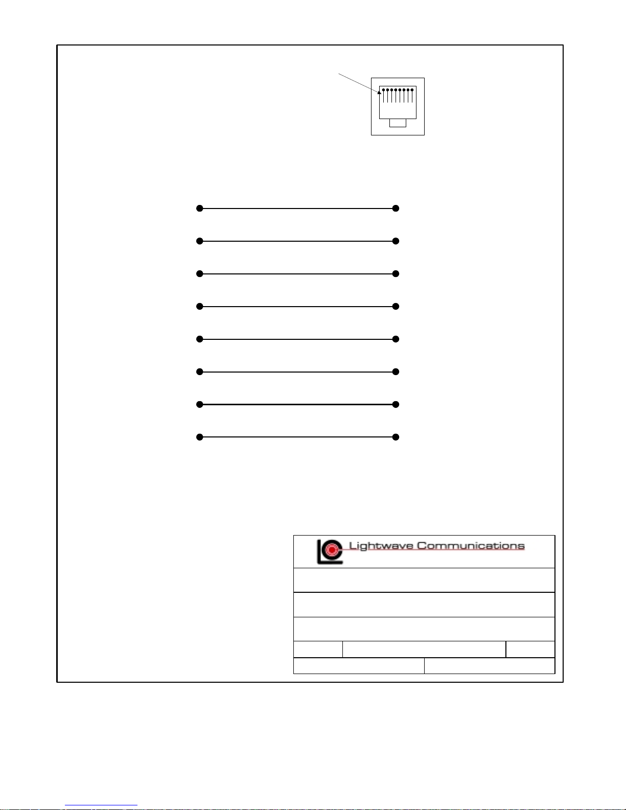
pin 1
DB25
MALE
2
3
4
5
6
7
8
20
RJ45
3
2
7
8
6
5
1
4
100 Washington Street, Milford CT 06460
800 871-9838 * Fax 203 874-0157 * www.lightwavecom.com
Title:
Part Number
Drawing Number
Size:
RJ45 Receptical to DB25M Adapter
200.0066
700.200.0066
System:
AA
200d0066.vsd 0101
ConsoleServer 3200
SheetFile:
Rev:
of
63
Page 68
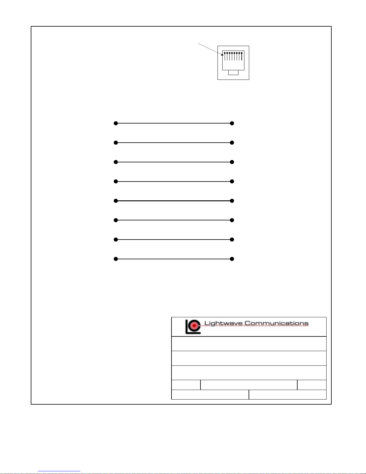
pin 1
DB25
FEMALE
2
3
4
5
6
7
8
20
RJ45
3
2
7
8
6
5
1
4
100 Washington Street, Milford CT 06460
800 871-9838 * Fax 203 874-0157 * www.lightwavecom.com
Title:
Part Number
Drawing Number
Size:
RJ45 Receptical to DB25F Adapter
200.0067
700.200.0067
System:
AA
200d0067.vsd 0101
ConsoleServer 3200
SheetFile:
Rev:
of
64
Page 69
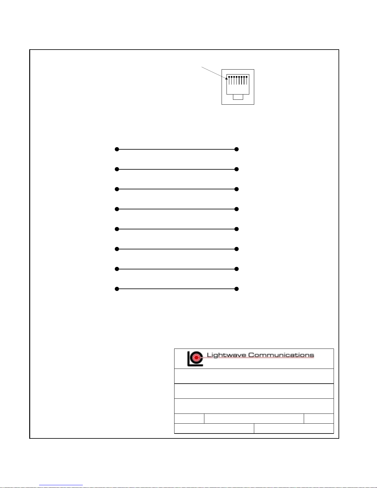
pin 1
DB9
FEMALE
1
2
3
4
5
6
7
8
RJ45
1
2
3
4
5
6
7
8
100 Washington Street, Milford CT 06460
800 871-9838 * Fax 203 874-0157 * www.lightwavecom.com
Title:
Part Number
Drawing Number
Size:
AA
RJ45 Receptical to DB9F Adapter
200.0070
700.200.0070
System:
200d0070.vsd 0101
ConsoleServer 3200
SheetFile:
Rev:
of
65
Page 70
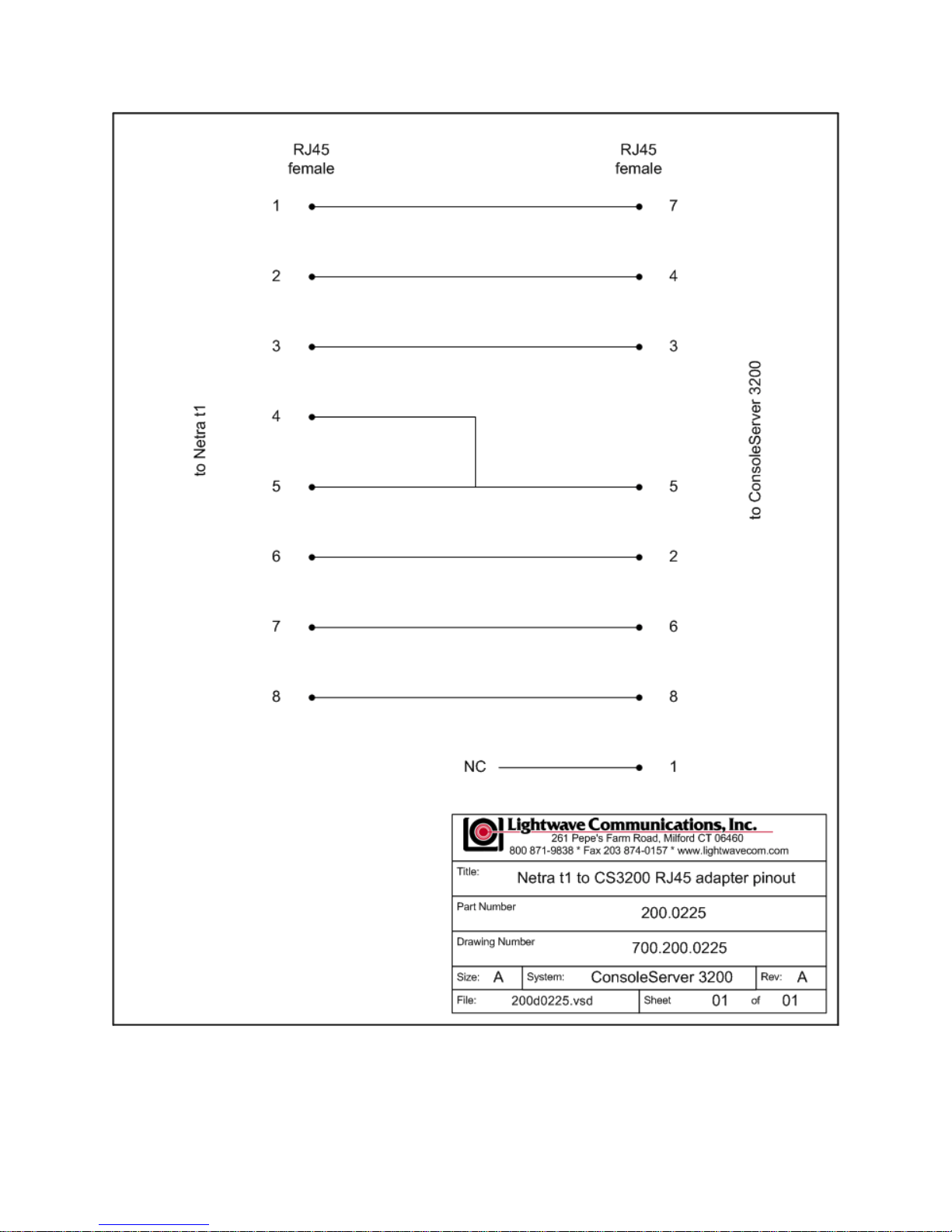
66
Page 71

Appendix B – Field Update of Console Server 3200 Flash Memory
B.1 Introduction
The system administrator may desire to update the software held in flash memory. The
modem, terminal, network, device, and control cards all have field-programmable flash
memory. Switch cards are not programmable in the field.
The flash software may be updated by two means: through a direct serial connection, or
via network.
B.2 Requirements
Direct Serial Connection:
• terminal or computer capable of communication with control card
• ability to upload binary files using kermit or Xmodem (see NOTE below)
• latest flash software files
Network Update:
• installed and configured network card
• latest flash software files
• tftp server
• network or direct serial connection to the sys admin login
The latest versions of software may always be obtained at Lightwave Communications’
FTP site, ftp.lightwavecom.com , accessible from any web browser or FTP client
program. The full URL to the latest ConsoleServer 3200 flash software updates,
procedures and instructions is:
ftp://ftp.lightwavecom.com/pub/products/3200/software/
There are two hardware versions of the control, terminal, and device cards: those with a
40-pin ROM containing the boot code, and those with flash only. The easiest way to tell
the difference is by looking at the card surface. If there is a large 40-pin ROM mounted
in a socket on the card, then it is the ROM/flash version. There are two different
versions of the flash update files corresponding to the two hardware versions. The files
prefaced with an "f" are for the flash-only versions, while those prefaced with an "r" are
for the ROM/flash versions of the cards. The ConsoleServer will reject the update if the
incorrect file is sent. Simply send the other file version if the first file is rejected.
NOTE:
To determine if the control card is capable of receiving Kermit protocol uploads, enter
the VERSION command at the sys admin> prompt. If the boot code version (not
67
Page 72
application code version, which is listed first) is greater than 1.70, then Kermit may be
used to transfer the binary update files; otherwise, Xmodem must be used.
B.3 Getting Started
Before initiating the flash update process, the system administrator must check that
there are no active users on the ConsoleServer 3200 by using the CONNECTIONS
command. If there are any users logged in, they should be notified to log out
immediately or forcibly logged out by using the FORCELOGOUT command.
B.3.1 Communications Settings
The communications settings are slightly different for the serial flash update than for the
normal operation mode. The baud rate, date bits, parity, and stop bits all remain the
same between modes, but the flow control changes. In the flash update mode, the flow
control changes to hardware flow control (RTS/CTS). Once the system returns to
normal operating mode, software flow control (XON/XOFF) is used.
B.4 Update over Direct Serial Connection
The terminal or computer that will be used for the flash update must be connected to the
control card port “A”. All users must be logged out. The system administrator must log
in before beginning the update. Commands that the sys admin should enter and text
returned by the ConsoleServer 3200 are in Lucida Console font. All commands
should be followed by <ENTER>.
sys admin>LCIUPDATE
Start system update, are you sure? (write out YES) Yes or No: No>YES
Once there are no users logged in, the system administrator must type LCIUPDATE to
initiate the flash update process. The ConsoleServer 3200 will ask the system
administrator if he is sure by displaying the prompt START SYSTEM UPDATE, ARE
YOU SURE? (PLEASE TYPE OUT YES) YES OR NO: NO>. If the system
administrator wants to proceed with the update, he should type out YES completely and
press <ENTER>. Otherwise, NO or just N and <ENTER> will exit the process.
ConsoleServer 3200 Control Boot V1.26 (Jun 15 1999)
Copyright 1999 by Lightwave Communications, Inc. All rights reserved.
Slot (letter) Processor (number) Ex. C1 (exit to restart system):B1
B1 is ConsoleServer3200 Terminal Boot V1.62 (Sep 30 1999)
Start XMODEM transfer of update...
CCCCCCCCCC
After typing YES, the ConsoleServer 3200 will return the prompt SLOT (LETTER)
PROCESSOR (NUMBER) EX. C1 (EXIT TO RESTART SYSTEM). The system
administrator should enter the letter ID of the card and number of the processor that is
68
Page 73

to be updated at this prompt. See page XX for slot letter ID’s. For most cards, the
processor number will be 1; network cards have two processors: processor 1 is the user
interface to the network card (use netterm.bin), while processor 2 is the network
interface (use network.bin). After the system administrator enters the card ID, the
ConsoleServer 3200 will return the prompt YY IS CONSOLESERVER3200 CCCCCC
BOOT VX.XX (DDD DD DDDD) START XMODEM TRANSFER OF UPDATE....,
where YY is the card ID, CCCCCC is the card type, X.XX is the boot ROM version
number, and DDD DD DDDD is the date of the boot ROM version. When using
XMODEM, this prompt will be followed by the letter "C", which will keep appearing on
the screen, indicating the control card is ready to accept the download.
Received: V2.15 10/01/99 TERMINAL SOFTWARE
Continue with programming? (y/n) Y
Sending update to B1
Download Successful, starting to program..............................
Programming Successful
Slot (letter) Processor (number) Ex. C1 (exit to restart system):
The system administrator should begin the upload of the appropriate flash update from
their computer at this point. Once the upload is complete, the ConsoleServer 3200 will
return the prompt RECEIVED VX.XX DD/DD/DD CCCCCC SOFTWARE CONTINUE
WITH PROGRAMMING? (Y/N), where X.XX is the version number of the newly
downloaded software, DD/DD/DD is the date of the software and CCCCCC is the card
type. If the system administrator wishes to continue with the update, he should type Y;
otherwise to end, he should type N, which will return the system administrator to the
previous flash update prompt.
Once Y is selected, the message SENDING UPDATE TO XX (where XX is the card ID)
will appear, which will be immediately be followed by DOWNLOAD SUCCESSFUL,
STARTING TO PROGRAM...........and then PROGRAMMING SUCCESSFUL. The
control card will then display the original update prompt. If the system administrator
wishes to continue updating cards, he should enter the card ID at the prompt. When
programming multiples of the same card type in one session, it is not necessary to
download the flash update again. The ConsoleServer 3200 will ask the system
administrator if the previously downloaded flash upgrade can be used again. If the
system administrator wishes to upload the update again, they can decline to reuse the
previously uploaded version and upload the update again as outlined above.
B.5 Update over Network
A flash update file download may be initiated from either a network sys admin session
or a local serial sys admin session. If connected via network, only the network card
used for the session may download from the tftp server. A local serial session may
specify the network card slot to use for the update download as a qualifier after the
command. In either case, no other sys admin session activity is allowed while the
download in progress.
69
Page 74

The tftp server must be specified by a numerical IP address. The file path and name on
the server is specified after the IP address.
local serial connection:
sys admin>> tftp /b 172.16.1.1:fdevice.bin
Starting tftp download.................................................
.......................................................................
.........................
Download complete.
sys admin>>
In the example above, the sys admin is connected through a local serial connection.
The tftp download is performed through slot b (/b qualifier) from the tftp server at
172.16.1.1, and the file fdevice.bin is retrieved.
network session:
sys admin>> tftp 172.16.1.1:fdevice.bin
Starting tftp download.................................................
.......................................................................
..........................
Download complete.
sys admin>>
In the example above, the sys admin is connected through a network session. The tftp
download is performed through the same card to which the sys admin is connected.
sys admin>> tftpkill
If for some reason the tftp download must be halted, the command TFTPKILL can be
entered at the sys admin>> prompt to stop any download in progress. This must be
entered at the local serial connection or at a remote Sys Admin session to a network
card other than that used by the tftp transfer.
sys admin>> lciupdate /tftp h1
Once a flash update file has been downloaded via tftp, it can be sent to the appropriate
card using the LCIUPDATE command with the qualifier /TFTP. This sends the last
downloaded file to the card processor specified.
70
Page 75

B.6 Ending the Flash Update
Slot (letter) Processor (number) Ex. C1 (exit to restart system): EXIT
Starting system
ConsoleServer 3200 Control Boot V1.26 (Jun 15 1999)
Copyright 1999 by Lightwave Communications, Inc. All rights reserved.
Starting system
Lightwave Communications, Inc. ConsoleServer 3200
Please wait...system initializing
Checking page 30
Once the flash update is completed for all selected cards, the system administrator
must type EXIT at the update prompt. Once <ENTER> is pressed, the ConsoleServer
3200 will restart and the standard start-up messages will be displayed. Once the
ConsoleServer 3200 has checked the memory pages (and reset those necessary), the
LCI3200>> prompt will be displayed and the system administrator may login. On the
first log in after the flash update, it recommended that the system administrator check
the software versions by using the VERSION /ALL command. Once the LCI3200>>
prompt appears on the control card, users may log back in and connect to servers as
before the update.
71
Page 76

72
SWITCH
BBBBBBBB
BDD
CC
DDDDDD
CCCCCC
DEVICE
AAA
DEVICE CONTROL
A
A
AAAA
DEVICE DEVICE DEVICEDEVICEDEVICEDEVICE
BBBB
DDDD
0
I
CCCC
AAAA
TERMINAL
TERMINAL SWITCH
TERMINAL TERMINALMODEM
Sl o t s f o r
programming
purposes
0
I
Page 77

Appendix C – System Specifications
C.1 Physical
Width: 17.25 inches (43.82 cm)
Depth: 14.75 inches (37.47 cm)
Height: 5.25 inches (13.34 cm)
Rack size: 3u high, mounts in EIA-standard 19-inch rack
Weight fully loaded: 20 lbs. (9.08 kg)
C.2 Environmental
Operating temperature range: 32°F (0°C) to 125°F (52°C)
Operating humidity range: 30% to 90% RH, non-condensing
Storage temperature range: -4°F (-20°C) to 158°F (70°C)
Storage humidity range: 10% to 90% RH, non-condensing
Heat generated in normal operation: 170.6 BTU/hr
C.3 Electrical
Both the AC and DC power versions of the ConsoleServer feature redundant power
supplies.
C.3.1 AC Power
Universal input voltage, auto-switched AC power supplies, switch fused
Input voltage: 115/230 VAC
AC frequency: 50/60 Hz
Maximum power consumption: 65 W
Typical power consumption: 50 W
C.3.2 DC Power
48 volt only, externally fused
Input voltage: -48 VDC
Maximum power consumption: 65 W
Typical power consumption: 50 W
73
Page 78

C.4 Interface
C.4.1 Terminal and Device
Connector: RJ45 with adapters for EIA-standard
connectors (DB9 and DB25)
Specification: EIA-232
Maximum baud rate: 38400
Minimum baud rate: 9600
C.4.2 Network
Connector: RJ45
Protocol: TCP/IP (version 4)
Maximum speed: 10 Mbits, half duplex
Auto-negotiation: NOT SUPPORTED
C.4.3 Modem
Format: analog POTS
Maximum speed: 38400 baud
C.5 Compliance and Certification
Entela Electrical Safety Certification (equivalent to UL 1950 and CSA 950)
Entela is a USA OSHA Nationally Recognized Testing Laboratory (NRTL), an
accredited Certification Organization by the Standards Council of Canada (SCC),
and an IECEE – CB Scheme National Certifi c ations Body (NCB) & Certification
Body Testing Laboratory (CBTL).
CE 61000-3-2, 61000-3-3, 55022, 55024, and 60950 (LVD)
AS/NZS 3548 (C-tick approved)
Conforms to FCC part 15, class A
Conforms to VCCI standards
74
Page 79
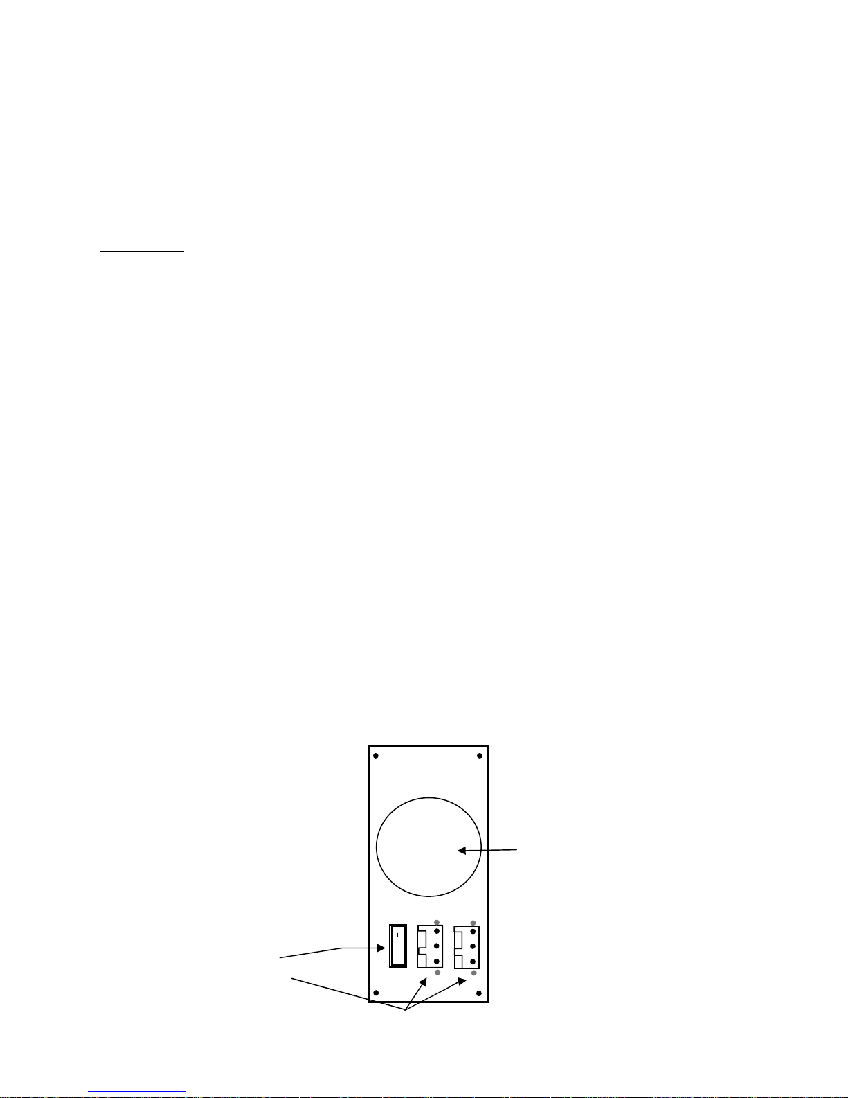
Appendix D -DC Power
The DC power version of the ConsoleServer 800 must be installed in a restricted access
location. Per the intent of the National Electrical Code, a restricted access location is an
area intended for access by qualified or trained personnel only, with access controlled by
some sort of locking mechanism, such as a key lock or access card system.
Installation:
Materials:
• small flat-blade screwdriver
• wire stripper
• ConsoleServer 800 DC power connector kit
• wires to 48 VDC power (see Appendix D for specifications)
1. Turn off the circuit breaker to the DC power supply.
2. Select a three-wire set (-48V, –48 Return, and Power Supply Ground) from the
power supply.
3. Strip 0.35 inches (89 mm) of insulation from each wire.
4. Insert a small flat-blade screwdriver in the provided connector to depress the
internal wire clamp.
5. Insert the appropriate wire into the connector. Remove the screwdriver. Check
that the clamp has captured the wire. Repeat steps 4 and 5 for all wires.
6. Attach the provided strain relief to the connector. Be sure to use a tie-wrap to
firmly attach the strain relief to the cable.
7. Attach the connector to the socket on the back of the ConsoleServer. Repeat the
above steps to attach the redundant power input.
Fan
Power On/Off Switch
Feed Through Headers
o
48V Return
PSU Gnd
-48V DC
75
Page 80

Input voltage: -48 VDC
Minimum voltage: -40 VDC
Maximum voltage: -60 VDC
Maximum operating current: 1.5 A
Maximum input surge current: 5 A
76
Page 81

The DC power source must be:
• electrically isolated from any AC source
• reliably connected to earth
• capable of providing up to 100 Watts of continuous power
D.2 Overcurrent Protection
Overcurrent protection requirements:
• 10 Amp trip
• double pole
• fast trip
• DC rated
• Overcurrent protection devices (e.g., circuit breakers) must be provided as part of
each equipment rack, and are not included with the ConsoleServer.
• The device must be located between the DC power source and the
ConsoleServer.
D.3 DC Supply Connector
The supply input connectors are provided with each ConsoleServer. However, the
conductors are not. See below for conductor specifications.
Conductor material: copper only
Wire gauge: 16 AWG
Insulation rating: 75°C minimum, low smoke fume, flame
retardant
Branch circuit cable insulation color: per applicable national electrical codes
Grounding cable insulation color: green/yellow
The cable type should be one of the following:
• UL style 1028 or other UL 1581 (VW-1) compliant equivalent
• IEEE 383 compliant
• IEEE 1202-1991 compliant
77
Page 82

Appendix E – Command Abbreviations
Most, but not all, commands available on the ConsoleServer 3200 may be abbreviated.
The following list outlines the allowed maximum abbreviations for all commands.
Command qualifiers for a command may be found immediately below that command.
Sys Admin Commands:
command
abbreviation
adduser addu, au
backup backup
break break
changepswd passwd, pswd
connections c
/monitor /m
deleteuser deleteu
devices dev
/all /a
edituser editu, eu
forcelogout forcelogout
help h, ?
info info
lciupdate lciupdate
/tftp /tftp
linesperpage linespp, lines, lpp
listcards listc, lc
listdevices listd, ld
listusers listu, lu
/all /a
login logi
logout, logoff lo
modem modem
modemtimeout modemt, mt
network net
/all /a
powerstatus po, ps
telnettimeout telnett, tt
terminals term
/all /a
timeout time
version ver
/all /a
78
Page 83

Terminal, Network, and Modem Commands:
command abbreviation
bottom bo
bye bye
changepswd ch
clear cl
connections co
devlist de
direct dir
diselect dis
editbrk editb
editesc edite
exit ex
forward f
listen li
login logi
logout, logoff logou, logof
next n
passwd pa
previous pr
reverse r
select se
top t
79
Page 84
Appendix F – Hexadecimal ASCII Code
Equivalent characters in italics are non-printing characters or signals.
Hexadecimal
Code
00
01
02
03
04
05
06
07
08
09
0A
0B
0C
0D
0E
0F
10
11
12
13
14
15
16
17
18
19
1A
1B
1C
1D
1E
1F
Equivalent
Character
NUL
SOH
STX
ETX
EOT
ENQ
ACK
BEL
BS
HT
NL
VT
NP
CR
SO
SI
DLE
DC1
DC2
DC3
DC4
NAK
SYN
ETB
CAN
EM
SUB
ESC
FS
GS
RS
US
Hexadecimal
Code
20
21 !
22 “
23 #
24 $
25 %
26 &
27 ‘
28 (
29 )
2A *
2B +
2C ,
2D 2E .
2F /
30 0
31 1
32 2
33 3
34 4
35 5
36 6
37 7
38 8
39 9
3A :
3B ;
3C <
3D =
3E >
3F ?
Equivalent
Character
SP
80
Page 85
Hexadecimal
Code
40 @ 60 `
41 A 61 a
42 B 62 b
43 C 63 c
44 D 64 d
45 E 65 e
46 F 66 f
47 G 67 g
48 H 68 h
49 I 69 i
4A J 6A j
4B K 6B k
4C L 6C l
4D M 6D m
4E N 6E n
4F O 6F o
50 P 70 p
51 Q 71 q
52 R 72 r
53 S 73 s
54 T 74 t
55 U 75 u
56 V 76 v
57 W 77 w
58 X 78 x
59 Y 79 y
5A Z 7A z
5B [ 7B {
5C \ 7C |
5D ] 7D }
5E ^ 7E ~
5F _ 7F
Equivalent
Character
Hexadecimal
Code
Equivalent
Character
DEL
81
Page 86

Index
Abbreviations – 16, 19-20, 45, 76-77
Backing up system settings – 39-40
Breaks – 2, 5
editing generation sequence - 55
sending - 55
Buffers – 2, 3, 25, 49
clearing content – 22, 54
viewing content – 49, 52-54
Cards – 1-6
listing installed cards – 33, 59-60
processors – 34, 67-68
slot letters – 33, 39, 67-68, 71
system information (INFO command) – 34-35
Connections to Devices – 3, 5-6
breaking (from sys admin) – 37-39
breaking (from user) - 49
checking (from front panel) – 57-58
checking (from sys admin) – 31-32
checking (from user) – 47-48
listening to – 21, 47, 49-50
making – 48-52
Device Card – 1, 5
connecting servers to – 12-14
directly accessing ports - 51
listening to port connections – 21, 47, 49-50
numbering of ports – 15, 22
selecting ports – 47-52
setting port parameters – 25-26
viewing port buffers – 52-54
Front Panel - 5
accessing information – 57-60
Modem Card – 1-4, 6
checking settings - 34
connecting to - 43
idle timeout - 39
setting initialization string – 30-31
82
Page 87

see also: User
Network Card – 1-3, 5-6
checking settings – 34-35
connecting to – 42-43
idle timeout – 38-39
setting parameters – 27-30
see also: User
Passwords – 1, 3 17-18, 46-47
changing sys admin - 20
changing user – 21, 23, 40-47
Power Supplies – 1, 5
checking status – 35, 60
Rack Mount - 7
Restoring System Settings - 40
Software - 1
updates – 41, 66-71
version – 33, 56, 70
Sys Admin – 14, 16-41
changing password - 20
connecting terminal – 8-9
logging in – 17-18
logging out - 18
timeout - 37
Terminal Card - 5
numbering of ports – 15, 27
setting parameters – 26-27
see also: User
Timeout
modem connections - 39
network conections – 38-39
sys admin sessions - 37
User – 1, 42-54
changing parameters - 23
changing password – 23, 46-47
creating – 21-23
deleting – 24-25
83
Page 88

directly interacting with device port – 51-52
editing break sequence - 55
editing direct mode escape sequence – 51-52
logging in - 46
logging out - 47
selecting device – 48-49
84
 Loading...