

Page 1
CoBox-FL/CoBox-FL-IAP
User Guide
Part Number 900-285
Revision E 8/03
Page 2

Copyright and Trademark
© 2003, Lantronix. All rights reserved. No part of the contents of this book may be
transmitted or reproduced in any form or by any means without the written permission of
Lantronix. Printed in the United States of America.
Ethernet is a trademark of XEROX Corporation. UNIX is a registered trademark of The Open
Group. Windows 95, Windows 98, Windows 2000, and Windows NT are trademarks of
Microsoft Corp. Netscape is a trademark of Netscape Communications Corporation.
Lantronix
15353 Barranca Parkway
Irvine, CA 92618, USA
Phone: 949-453-3990
Technical Support
Phone: 800-422-7044 or 9949-453-7198
Fax: 949-450-7226
On-line: www.lantronix.com/support
Page 3

Disclaimer and Revisions
Operation of this equipment in a residential area is likely to cause interference in which case
the user, at his or her own expense, will be required to take whatever measures may be
required to correct the interference.
Attention: This product has been designed to comply with the limits for a Class A
digital device pursuant to Part 15 of FCC Rules. These limits are designed to
provide reasonable protection against such interference when operating in a
commercial environment. This equipment generates, uses, and can radiate radio
frequency energy, and if not installed and used in accordance with this guide, may
cause harmful interference to radio communications.
Changes or modifications to this device not explicitly approved by Lantronix will void the
user's authority to operate this device.
The information in this guide may change without notice. The manufacturer assumes no
responsibility for any errors which may appear in this guide.
Date Rev. Comments
07/01/01 C Current release.
09/25/02 D Revised for Device Installer, new format. Includes all
CoBox-FL devices.
08/25/03 E Updated warranty information.
Page 4

Declaration of Conformity
(according to ISO/IEC Guide 22 and BS 7514)
Manufacturer’s Name & Address:
Lantronix, 15353 Barranca Parkway, Irvine, CA 92618 USA
Declares that the following product:
Product Name Model: CoBox-FL/CoBox-FL-IAP Device Server
Conforms to the following standards or other normative documents:
Safety: EN60950:1992+A1, A2, A3, A4,A11
Electromagnetic Emissions:
FCC Part 15, Subpart B, Class A
EN55022: 1998 (CISPR 22, Class A: 1993, A1: 1995, A2: 1996)
IEC 1000-3-2/A14: 2000
IEC 1000-3-3: 1994
Electromagnetic Immunity:
EN55024: 1998 Information Technology Equipment-Immunity Characteristics
IEC61000-4-2: 1995 Electro-Static Discharge Test
IEC61000-4-3: 1996 Radiated Immunity Field Test
IEC61000-4-4: 1995 Electrical Fast Transient Test
IEC61000-4-5: 1995 Power Supply Surge Test
IEC61000-4-6: 1996 Conducted Immunity Test
IEC61000-4-8: 1993 Magnetic Field Test
IEC61000-4-11: 1994 Voltage Dips & Interrupts Test
(L.V.D. Directive 73/23/EEC)
Supplementary Information:
This Class A digital apparatus has been verified as being compliant within the Class A limits of
the FCC Radio Frequency Device Rules (FCC Title 47, Part 15, Subpart B CLASS A), measured
to CISPR 22: 1993 limits and methods of measurement of Radio Disturbance Characteristics of
Information Technology Equipment. The product complies with the requirements of the Low
Voltage Directive 72/23/EEC and the EMC Directive 89/336/EEC.
Manufacturer’s Contact:
Director of Quality Assurance, Lantronix
15353 Barranca Parkway, Irvine, CA 92618 USA
Tel: 949-453-3990
Fax: 949-453-3995
Page 5

Warranty
Lantronix warrants each Lantronix product to be free from defects in material and
workmanship for a period of ONE YEAR after the date of shipment. During this period, if a
customer is unable to resolve a product problem with Lantronix Technical Support, a Return
Material Authorization (RMA) will be issued. Following receipt of a RMA number, the
customer shall return the product to Lantronix, freight prepaid. Upon verification of warranty,
Lantronix will -- at its option -- repair or replace the product and return it to the customer
freight prepaid. No services are handled at the customer's site under this warranty. This
warranty is voided if the customer uses the product in an unauthorized or improper way, or in
an environment for which it was not designed.
Lantronix warrants the media containing its software product to be free from defects and
warrants that the software will operate substantially according to Lantronix specifications for
a period of 60 DAYS after the date of shipment. The customer will ship defective media to
Lantronix. Lantronix will ship the replacement media to the customer.
In no event will Lantronix be responsible to the user in contract, in tort (including
negligence), strict liability or otherwise for any special, indirect, incidental or consequential
damage or loss of equipment, plant or power system, cost of capital, loss of profits or
revenues, cost of replacement power, additional expenses in the use of existing software,
hardware, equipment or facilities, or claims against the user by its employees or customers
resulting from the use of the information, recommendations, descriptions and safety notations
supplied by Lantronix. Lantronix liability is limited (at its election) to:
1) refund of buyer's purchase price for such affected products (without interest)
2) repair or replacement of such products, provided that the buyer follows the above
procedures.
There are no understandings, agreements, representations or warranties, expressed or implied,
including warranties of merchantability or fitness for a particular purpose, other than those
specifically set out above or by any existing contract between the parties. Any such contract
states the entire obligation of Lantronix. The contents of this document shall not become part
of or modify any prior or existing agreement, commitment or relationship.
Page 6

Sales Offices
The Americas
15353 Barranca Parkway
Irvine, CA 92618, USA
Phone: (949) 450-7227
Fax: (949) 450-7231
sales@lantronix.com
France
2 Rue Hélène Boucher
78280 Guyancourt
France
Tel: +33 1 39 30 41 74
Fax: +33 1 39 30 41 73
europesud@lantronix.com
Germany
Karlstrasse 49
78054 VS-Schwenningen
Germany
Tel: +49 (0)77 20 30 1620
Fax: +49 (0)77 20 30 1688
ursula.koch@lantronix.com
Asia Pacific
16th Floor
Cheung Kong Center
2 Queen's Road Central
Hong Kong
Tel: +852 2297 2287
Fax: +852 2297 2357
asiapacsales@lantronix.com
EMEA Sales
(Europe, Mid East, Africa)
eu_sales@lantronix.com
eu_order@lantronix.com
EMEA Technical Support
+49 (0) 7720 3016 20/57
eu_techsupp@lantronix.com
Page 7

Contents
Table of Contents
1. Introduction...................................................................................................................... 1-1
1.1 CoBox-FL ........................................................................................................... 1-1
1.2 CoBox-FL-IAP Device Server............................................................................ 1-2
1.2.1 Industrial Automation Protocols......................................................... 1-3
1.3 Network Protocols .............................................................................................. 1-4
1.3.1 Packing Algorithm.............................................................................. 1-4
1.3.2 IP Address........................................................................................... 1-4
1.3.3 Port Number........................................................................................ 1-4
1.4 Serial Interface.................................................................................................... 1-5
1.4.1 Channel 1 ............................................................................................ 1-5
1.4.2 Channel 2 ............................................................................................ 1-6
1.5 RJ-45 Ethernet Interface ..................................................................................... 1-6
1.6 RJ-45 Ethernet Connector................................................................................... 1-7
1.7 ST-Fiber Ethernet Connectors ............................................................................ 1-7
1.8 Serial Interface Cable.......................................................................................... 1-8
1.9 Network LEDs .................................................................................................... 1-8
1.10 Serial LEDs....................................................................................................... 1-9
1.11 Dimensions ..................................................................................................... 1-10
1.12 Product Information Label.............................................................................. 1-10
1.13 Software Support ............................................................................................ 1-10
1.14 Power Requirements ....................................................................................... 1-11
1.15 Technical Specifications ................................................................................. 1-12
2. Getting Started................................................................................................................. 2-1
2.1 Addresses and Port Number................................................................................ 2-1
2.1.1 Ethernet (MAC) Address .................................................................... 2-1
2.1.2 Internet Protocol (IP) Address ............................................................ 2-1
2.1.3 Port Number........................................................................................ 2-2
2.2 Physically Connecting the Unit .......................................................................... 2-2
2.3 Methods of Assigning the IP Address ................................................................ 2-3
2.3.1 DHCP.................................................................................................. 2-4
2.3.2 AutoIP................................................................................................. 2-4
2.4 DeviceInstaller .................................................................................................... 2-5
2.4.1 Install DeviceInstaller Software.......................................................... 2-5
CoBox-FL User Guide i
Page 8

Contents
2.4.2 Assign IP Address and Network Class................................................2-6
2.4.3 Test the IP Address..............................................................................2-7
2.4.4 Add the Unit to the Manage List ......................................................... 2-8
2.4.5 Opening a Configuration Window ....................................................2-10
2.5 ARP and Telnet .................................................................................................2-11
2.6 Serial Port Login ...............................................................................................2-12
3. Configuring the Unit ........................................................................................................3-1
3.1 Configuring via Web Browser.............................................................................3-1
3.2 Using DeviceInstaller ..........................................................................................3-2
3.3 Web Manager Page .............................................................................................3-4
3.3.1 Unit Configuration ..............................................................................3-5
3.3.2 Server Properties ................................................................................. 3-6
3.3.3 Port Properties .....................................................................................3-7
3.3.4 Technical Support................................................................................3-9
3.3.5 Update Settings ...................................................................................3-9
3.4 Configuring via the Setup Mode Window.........................................................3-10
3.4.1 Using a Telnet Connection ................................................................ 3-10
3.4.2 Using the Serial Port..........................................................................3-12
3.5 Server Configuration (Network Configuration) ................................................3-12
3.5.1 IP Address ......................................................................................... 3-12
3.5.2 Set Gateway IP Address ....................................................................3-12
3.5.3 Netmask: Number of Bits for Host Part ............................................3-13
3.5.4 Change Telnet configuration password ............................................. 3-14
3.5.5 DHCP Naming ..................................................................................3-14
3.6 Channel 1 Configuration (Serial Port Parameters)............................................3-15
3.6.1 Baudrate ............................................................................................3-15
3.6.2 I/F (Interface) Mode ..........................................................................3-15
3.6.3 Flow...................................................................................................3-16
3.6.4 Port Number ......................................................................................3-16
3.6.5 Connect Mode ................................................................................... 3-17
3.6.6 Remote IP Address............................................................................3-20
3.6.7 Remote Port....................................................................................... 3-20
3.6.8 DisConnMode ...................................................................................3-20
3.6.9 Flush Mode (Buffer Flushing)...........................................................3-21
3.6.10 Pack Control....................................................................................3-22
3.6.11 DisConnTime (Inactivity Timeout)................................................. 3-23
3.6.12 Send Characters...............................................................................3-23
3.6.13 Telnet Terminal Type......................................................................3-23
3.6.14 Channel (Port) Password................................................................. 3-23
3.7 Expert Settings ..................................................................................................3-24
3.7.1 TCP Keepalive time in s....................................................................3-24
CoBox-FL User Guide
ii
Page 9

Contents
3.8 Security Settings ............................................................................................... 3-24
3.8.1 Disable SNMP .................................................................................. 3-24
3.8.2 SNMP Community Name................................................................. 3-24
3.8.3 Disable Telnet Setup......................................................................... 3-25
3.8.4 Disable TFTP Firmware Upgrade..................................................... 3-25
3.8.5 Disable Port 77FE (Hex)................................................................... 3-25
3.8.6 Disable Web Server .......................................................................... 3-25
3.8.7 Enable Enhanced Password .............................................................. 3-25
3.9 Factory Defaults................................................................................................ 3-25
3.10 Exit Configuration Mode ................................................................................ 3-26
3.11 Get Configuration ........................................................................................... 3-26
3.12 Set Configuration............................................................................................ 3-27
4. Updating Protocol (Firmware) ....................................................................................... 4-1
4.1 Protocol Firmware .............................................................................................. 4-1
4.2 Reloading Protocol Firmware............................................................................. 4-1
4.2.1 Via DeviceInstaller ............................................................................. 4-2
4.2.2 Via TFTP ............................................................................................ 4-4
4.2.3 Via Another Unit ................................................................................ 4-5
4.2.4 Via the Serial Port............................................................................... 4-6
5. DeviceComm Manager .................................................................................................... 5-1
5.1 Installing DeviceComm Manager ....................................................................... 5-2
5.1.1 Install DeviceComm Manager ............................................................ 5-2
5.1.2 Setup ................................................................................................... 5-3
6. Troubleshooting ............................................................................................................... 6-1
6.1 Technical Support ............................................................................................... 6-1
6.1.1 Technical Support............................................................................... 6-1
7. Monitor Mode .................................................................................................................. 7-1
7.1 Monitor Mode..................................................................................................... 7-1
7.1.1 Entering Monitor Mode Via the Serial Port........................................ 7-1
7.1.2 Entering Monitor Mode Via the Network Port ................................... 7-1
7.1.3 Monitor Mode Commands.................................................................. 7-1
8. Network Configuration using UDP ................................................................................ 8-1
8.1 UDP Datagrams .................................................................................................. 8-1
8.2 Configuring Multiple Devices ............................................................................ 8-3
8.2.1 Acquiring a Valid Setup Record......................................................... 8-3
8.2.2 Sending a Setup Record...................................................................... 8-4
8.2.3 The Intel Hex Format.......................................................................... 8-5
8.2.4 Calculating the Checksum .................................................................. 8-6
8.2.5 Calculating the Two’s Complement ................................................... 8-6
CoBox-FL User Guide iii
Page 10

Contents
8.3 Setup Records...................................................................................................... 8-7
8.3.1 Channel Parameters.............................................................................8-8
8.3.2 Interface Mode ....................................................................................8-9
8.3.3 Baud Rate ..........................................................................................8-10
8.3.4 Flow Control .....................................................................................8-10
8.3.5 Connect Mode ................................................................................... 8-11
8.3.6 Disconnect Mode...............................................................................8-12
8.3.7 Flush Mode (Buffer Flushing)...........................................................8-13
8.3.8 Pack Control......................................................................................8-13
8.4 IP Addresses...................................................................................................... 8-14
8.4.1 Network Portion ................................................................................8-14
8.4.2 Subnet Portion ................................................................................... 8-14
8.4.3 Host Portion.......................................................................................8-15
8.4.4 Network Address...............................................................................8-15
8.4.5 Broadcast Address.............................................................................8-15
8.4.6 Private IP Networks and the Internet.................................................8-16
8.4.7 Network RFCs...................................................................................8-16
9. Binary to Hex Conversion................................................................................................9-1
9.1 Connect Mode Options........................................................................................9-1
9.2 Disconnect Mode Options ................................................................................... 9-5
9.3 Flush Mode (Buffer Flushing) Options ...............................................................9-7
9.4 Interface Mode Options.....................................................................................9-13
9.5 Pack Control Options ........................................................................................9-14
10. IP Addresses..................................................................................................................10-1
10.1 Class A Network .............................................................................................10-1
10.2 Class B Network..............................................................................................10-1
10.3 Class C Network..............................................................................................10-1
10.4 Network Address.............................................................................................10-2
10.5 Broadcast Address...........................................................................................10-2
10.6 IP Netmask ......................................................................................................10-2
10.7 Private IP Networks and the Internet...............................................................10-3
10.8 Network RFCs.................................................................................................10-3
11. Glossary.........................................................................................................................11-1
CoBox-FL User Guide
iv
Page 11

Contents
List of Figures
Figure 1 – CoBox-FL-IAP ..................................................................................................... 1-2
Figure 2 - RJ-45 Connector.................................................................................................... 1-7
Figure 3 – CoBox-FL Connected to Serial Device and Network .......................................... 2-2
Figure 4 – CD Main Window ................................................................................................ 2-5
Figure 5 - DeviceInstaller Window........................................................................................ 2-6
Figure 6 - Assign IP Address Window .................................................................................. 2-6
Figure 7 - Ping Device Window ............................................................................................ 2-7
Figure 8 - Search Network Window ...................................................................................... 2-8
Figure 9 - Devices in a Group................................................................................................ 2-9
Figure 10 - Device Management Window........................................................................... 2-10
Figure 11 - Lantronix Web-Manager..................................................................................... 3-4
Figure 12 - Server Properties Configuration on the Web Browser........................................ 3-6
Figure 13 - Setup Mode Window......................................................................................... 3-11
Figure 14 - Device Installer ................................................................................................... 4-2
Figure 15 - Search Network Window .................................................................................... 4-3
Figure 16 - Devices in a Group.............................................................................................. 4-3
Figure 17 - Upgrade Firmware .............................................................................................. 4-4
Figure 18 - TFTP Dialog Box................................................................................................ 4-5
Figure 19 – UDS/CoBox Main Window................................................................................ 5-2
Figure 20 - Sample Setup Record in Intel Hex Format.......................................................... 8-3
CoBox-FL User Guide v
Page 12

Contents
List of Tables
Table 1 - Ethernet Interface Signals .......................................................................................1-7
Table 2 - CoBox-FL LED Functions..................................................................................... 1-9
Table 3 - Technical Specs.....................................................................................................1-12
Table 4 - Standard IP Network Netmasks ............................................................................3-13
Table 5 - Netmask Examples................................................................................................3-13
Table 6 - Interface Mode Options ........................................................................................3-15
Table 7 - Common Interface Mode Settings ........................................................................3-16
Table 8 - Flow Control Options............................................................................................3-16
Table 9 - Connect Mode Options .........................................................................................3-17
Table 10 - Manual Connection Address Example................................................................ 3-18
Table 11 - Modem Mode Commands...................................................................................3-19
Table 12 - Disconnect Mode Options...................................................................................3-20
Table 13 - Flush Mode Options............................................................................................ 3-21
Table 14 - Pack Control Options.......................................................................................... 3-22
Table 15 - Protocol Firmware.................................................................................................4-1
Table 16 - Problems and Error Messages...............................................................................6-2
Table 17 - Monitor Mode Commands ....................................................................................7-2
Table 18 -Command Response Codes.................................................................................... 7-2
Table 19 - UDP Configuration ...............................................................................................8-1
Table 20 - Block Types .......................................................................................................... 8-5
Table 21 - Setup Record Construction ...................................................................................8-7
Table 22 - Channel Parameters...............................................................................................8-8
Table 23 - Interface Mode Options ........................................................................................8-9
Table 24 - Common Interface Mode Settings ........................................................................8-9
Table 25 - Baud Rate Settings.............................................................................................. 8-10
Table 26 - Flow Control Options..........................................................................................8-10
Table 27 - Connect Mode Options .......................................................................................8-11
Table 28 - Disconnect Mode Options...................................................................................8-12
Table 29 - Flush Mode Options............................................................................................ 8-13
Table 30 - Pack Control Options.......................................................................................... 8-13
Table 31 - Network Portion of IP Address...........................................................................8-14
Table 32 - Available IP Addresses .......................................................................................8-14
Table 33 - Standard IP Network Netmasks ..........................................................................8-15
Table 34 - Netmask Examples..............................................................................................8-16
Table 35 - Binary to Hexadecimal Conversion Table ............................................................9-1
Table 36 - Connect Mode Options .........................................................................................9-2
Table 37 - Connect Mode Options for Modem Emulation.....................................................9-4
CoBox-FL User Guide
vi
Page 13

Contents
Table 38 - Disconnect Mode Options .................................................................................... 9-5
Table 39 - Flush Mode Options ............................................................................................. 9-7
Table 40 - Interface Mode Options...................................................................................... 9-13
Table 41 - Pack Control Options ......................................................................................... 9-14
CoBox-FL User Guide vii
Page 14

Page 15
Introduction
11.. IInnttrroodduuccttiioonn
This manual describes the CoBox-FL family of Device Servers, including the CoBox-FL
Device Server and the CoBox-FL-IAP Device Server with Industrial Automation Protocols.
Most of the material in this manual applies to all of the CoBox-FL products. However, in
some cases there will be some features that apply to only one product. In those cases, a note
will explain the variation.
Note: In most cases CoBox-FL refers to CoBox-FL and CoBox-FL-IAP.
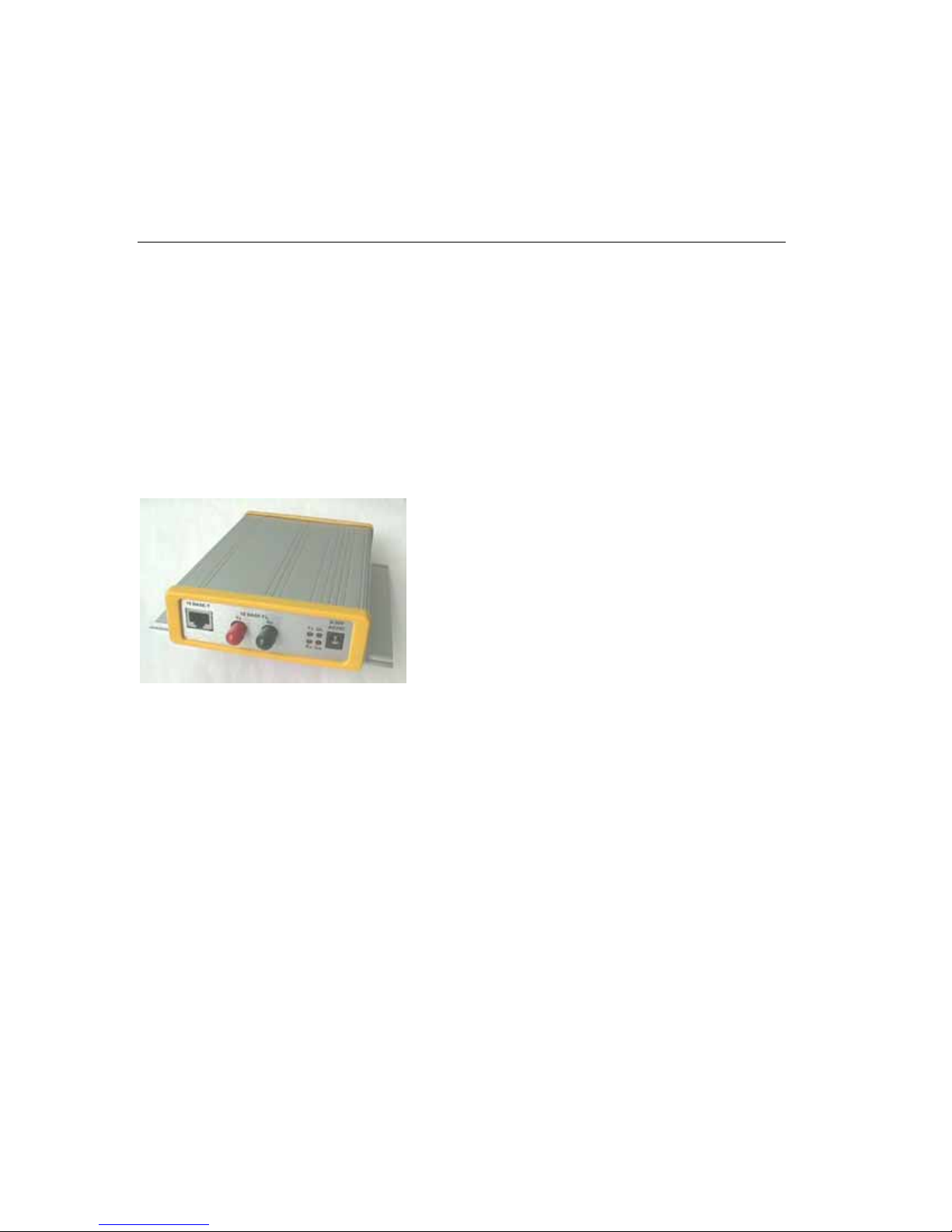
1.1 CoBox-FL
The CoBox-FL Device Server connects serial devices to Ethernet networks using the IP
protocol family (TCP for connection-oriented stream applications and UDP for datagram
applications). A few of the different types of serial devices supported are listed below:
• Time/Attendance Clocks and Terminals
• ATM Machines
• CNC Controllers
• Data Collection Devices
• Universal Power Supply (UPS) Management Units
• Telecommunications Equipment
• Data Display Devices
• Security Alarms and Access Control Devices
• Handheld Instruments
• Modems
The CoBox-FL connects these devices through a TCP data channel or through a Telnet
connection to computers or another Device Server. Datagrams can be sent by UDP.
The CoBox-FL supports RS-232, RS-422/485 through the DB-25F Channel 1 serial port. It
supports RS-232 through the DB-9M Channel 2 serial port. It supports 10Mb/s Ethernet
through an RJ-45 connector and through ST-Fiber connectors. It can be configured via HTTP,
SNMP, DHCP or Telnet. It contains a Flash ROM for easy software upgrades.
CoBox-FL User Guide 1-1
Page 16
Introduction
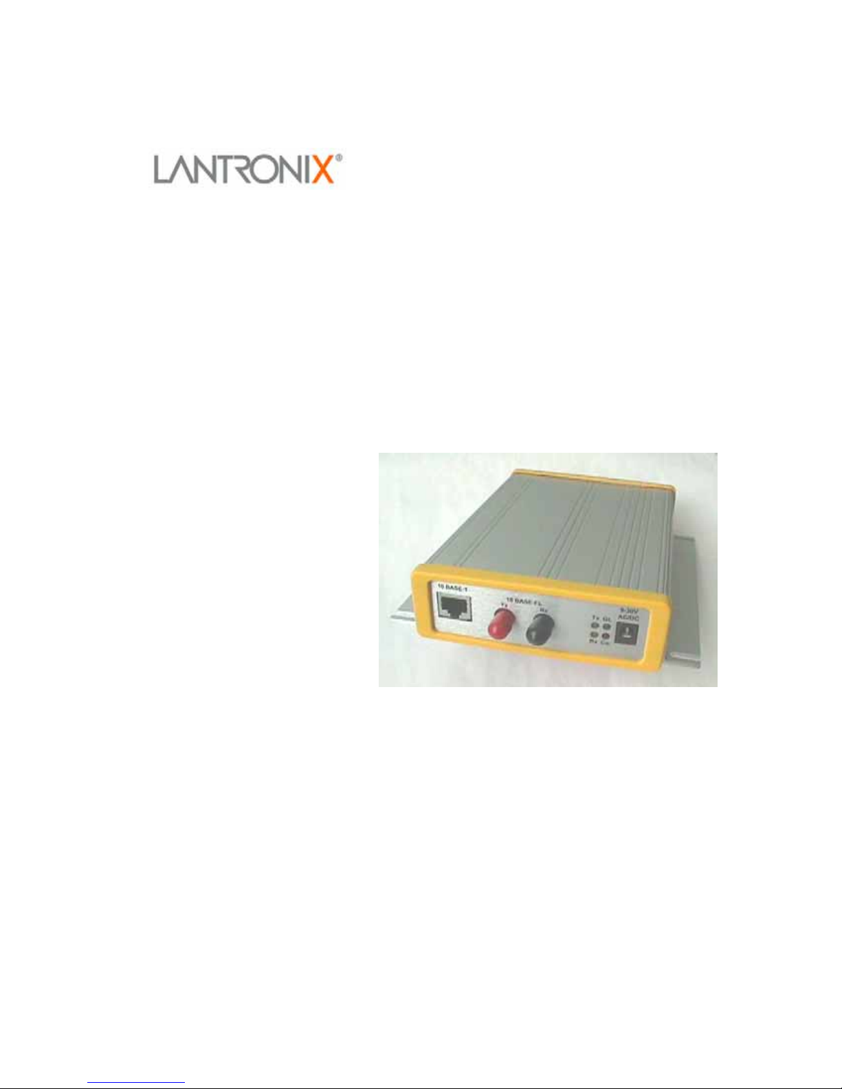
1.2 CoBox-FL-IAP Device Server
Note: This section is for the CoBox-FL-IAP only.
The Lantronix Industrial Automation Platform (IAP) family of Device Servers allows a single
network and protocol to connect multiple serial devices from many vendors. IAP provides
the automation industry with a network-enabling solution using TCP/IP and standard Ethernet
networks that is vendor-independent.
By encapsulating serial data and transporting it over Ethernet, the Device Server allows
virtual serial links to be established over Ethernet and IP (TCP/IP, UDP/IP) networks. As a
result, limited distance, point-to-point, direct serial connections can be extended within the
plant, throughout the facility, or across the global enterprise. The following picture is one of
the Device Servers in the IAP family.
Figure 1 – CoBox-FL-IAP
Lantronix provides IAP Device Servers specifically designed for different industrial
environments.
• CoBox-DR1-IAP, with a DIN rail interface for harsh environments or alongside
controls instruments in electrical panels.
• CoBox-FL-IAP, with fiber connectivity for long cable runs or electrically hazardous
environments.
• UDS-10-IAP, a compact Device Server for use in less demanding environments.
CoBox-FL User Guide
1-2
Page 17

Introduction
A few examples of attached devices are:
• PLCs
• AC/DC drives
• CNC systems
• Operator panels and message displays
• Process Controls
• Instrumentation
• Power monitoring equipment
• Scales and weighing systems
• Barcode scanners
• Label printers
• Most factory floor serial devices
1.2.1 Industrial Automation Protocols
IAP Device Servers, adapted to multiple factory environments, can unite any mixture of
equipment from industrial automation vendors into a single reliable pipeline. This new and
open infrastructure opens the way for data to flow in real time from all your plant devices up
to your IT layer.
IAP Device Servers are delivered with IAP Standard Tunneling protocol and can be loaded
with industrial communication protocols. The suite of protocols include DF1 (Rockwell
Automation) and Modbus (Schneider Electric). Where the IAP Standard Tunneling protocol
is limited to exclusive, standard ASCII device-to-device connections, the industrial protocols
offer connections to other devices that require special formatting or features simultaneously.
For information about using any of the industrial communication protocols, see the user
manuals on the software CD or our web site. Protocol firmware files are also contained on the
CD and new versions are available from the Lantronix web site.
You can set up the unit using the serial port, or remotely over Ethernet using Telnet or a web
browser. The CD that comes with your Device Server includes DeviceInstaller, a Windows
based configuration software that simplifies the process of installing protocols and
configuring them for use with attached devices. IAP Device Servers use Flash memory for
maintenance-free, non-volatile storage which allows for fast system upgrades.
CoBox-FL User Guide 1-3
Page 18

Introduction
1.3 Network Protocols
Note: CoBox-FL refers to CoBox-FL and CoBox-FL-IAP except where noted.
The CoBox-FL uses TCP/IP protocols for network communication. The supported standards
are: ARP, UDP, TCP, ICMP, Telnet, TFTP, DHCP, AutoIP, and SNMP. For transparent
connections, TCP/IP (binary stream) or Telnet protocols are used. Firmware upgrades can be
made with the TFTP protocol.
The IP (Internet Protocol) protocol defines addressing, routing, and data-block handling over
the network. The TCP (transmission control protocol) assures that no data is lost or
duplicated, and that everything sent into the connection on one side arrives at the target
exactly as it was sent.
For typical datagram applications where devices interact with others without maintaining a
point-to-point connection, UDP datagram is used.
1.3.1 Packing Algorithm
The two available packet algorithms (which define how and when packets are sent to the
network) are software selectable. The standard algorithm is optimized for applications where
CoBox-FL is used in a local environment, allowing for very small delays for single characters
while trying to keep the packet count low. The alternate packing algorithm minimizes the
packet count on the network and is especially useful for applications in routed Wide Area
Networks. Various parameters can be set in this mode to economize the serial data stream.
1.3.2 IP Address
Every active device connected to the TCP/IP network must have a unique IP address. This IP
address is used to reference a specific device, for example, to build a connection to CoBoxFL’s serial port. See Appendix A for a complete description of IP Addressing.
1.3.3 Port Number
A destination IP address and a port number define every TCP connection and every UDP
datagram. A port number is necessary to address an application or a channel on a network
host. The port number can be compared to an extension on a PBX system.
A Telnet application (login to a host with an ASCII terminal) is commonly assigned TCP port
number 23. More than one Telnet connection can be established to one host using the Telnet
port; however, the other peer IP address/port number combinations must be different.
In the CoBox-FL, a port number can be configured on the channel (port). The CoBox-FL uses
this port number for outgoing messages and incoming connections, or UDP datagrams, which
are addressed to its port number. Port 9999 (decimal) is used for remote configuration.
CoBox-FL User Guide
1-4
Page 19

Introduction
1
1.4 Serial Interface
The CoBox-FL has two serial ports. CH 1 uses a DB-25F (DCE) connector and supports RS232, RS-422/485. CH 2 uses a DB-9 connector and supports RS-232 only. It supports 10Mb/s
Ethernet through the RJ-45 (10BASE-T) connector or the ST-Fiber (10BASE-FL). It can be
configured via HTTP, SNMP, DHCP or Telnet. It contains a Flash ROM for easy software
upgrades.
1
H
e
t
a
t
S
2
H
C
C
DB-9 Serial Port
(DTE)
LEDs
DB-25 Serial Port
(DCE)
1.4.1 Channel 1
The CoBox-FL Channel 1 is a female DB-25F supporting RS-232C, RS-485, or RS-422 DCE
serial interface. The default serial port settings are 9600 baud, 8 data bits, no parity, and 1
stop bit.
14
)
13
TX+ (out)
TX- (out)
RS-232/485
DTR (input)
RX+ (in)
RX- (in)
25
TX (input)
RX (output)
RTS (i nput
CTS (output)
DSR (output)
GND
DCD (output)
Reg. +5VDC
(Note 1)
Reg. +9-30VDC
(Note 1)
Note 1: The Device Server can alternately be powered up via the serial port using one of
these pins.
Note 2: The minus sign (-) is sometimes shown as A (TXA), and the plus sign is sometimes
shown as B (TXB)
(Note 2)
DB-25F
(Note 2)
For RS-485 2-wire functionality, connect pin 14 to 21, and connect pin 15 to 22.
CoBox-FL User Guide 1-5
Page 20
Introduction
5
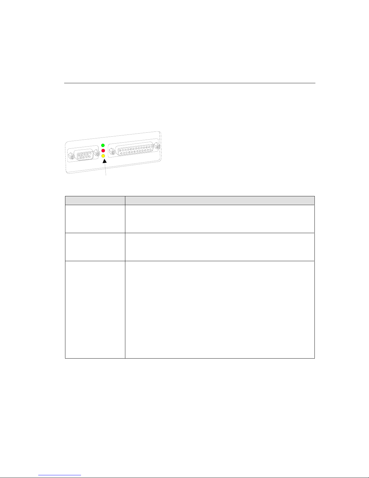
1.4.2 Channel 2
The CoBox-FL Channel 2 is a male DB-9M supporting RS-232C DTE serial interface.
1
9
CTSA (in)
RTSA (out)
6
GND
TRA (out)
TXA (out)
RXA(in)
DCDA (in)
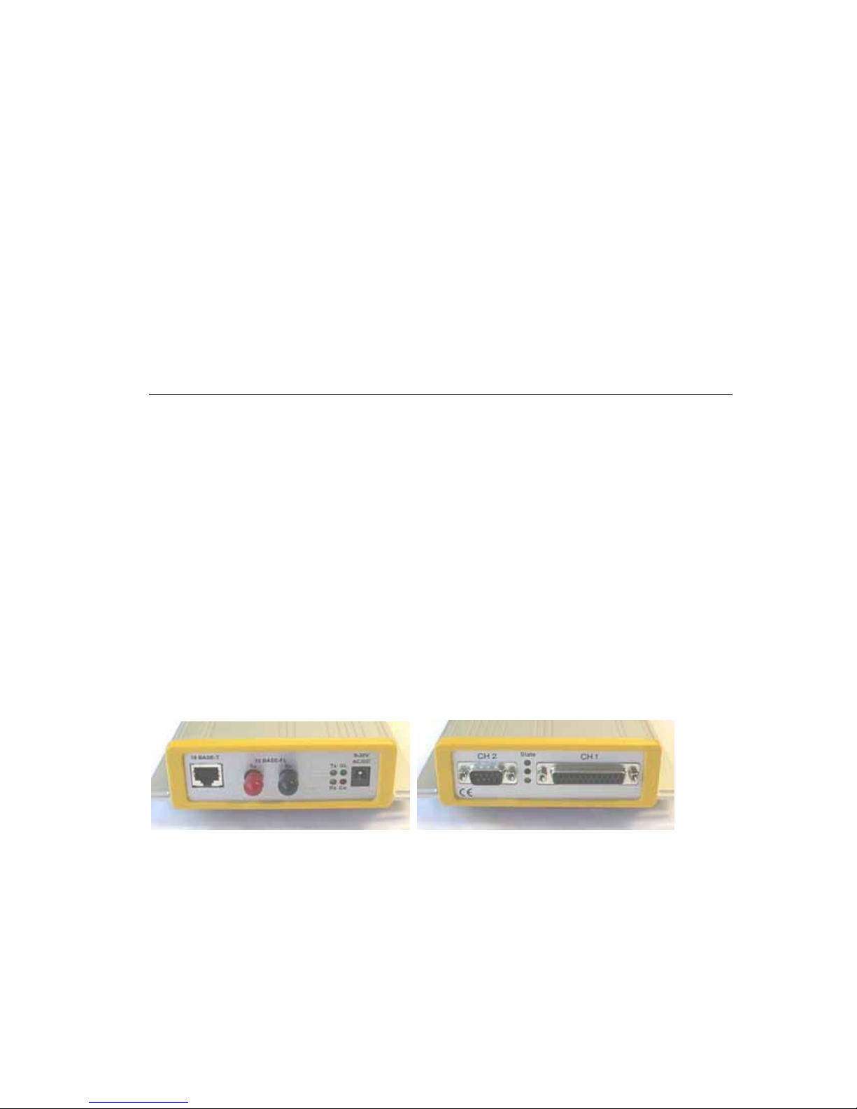
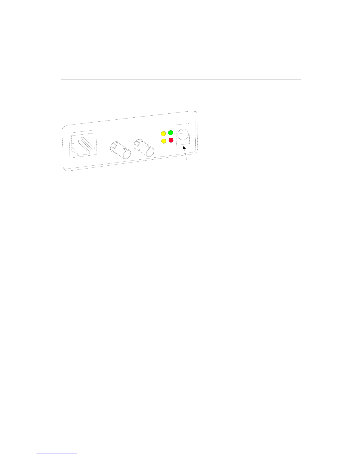
1.5 RJ-45 Ethernet Interface
The CoBox-FL’s back panel contains a 9-30V AC/DC power plug, four LEDs, an ST-Fiber
(10BASE-FL) Ethernet port, and an RJ-45 (10BASE-T) Ethernet port. Both Ethernet ports
support 10 Mbps and are auto detecting.
V
0
3
-
9
C
D
/
C
A
L
T
-
E
S
A
B
0
1
F
-
E
S
A
B
0
1
x
T
G
x
T
L
x
R
o
C
x
R
9-30V AC/DC
Power
10BASE-T
Ethernet Port
10BASE-FL
Ethernet Port
LEDs
Note: Do not attempt to connect both Ethernet ports simultaneously. If one is used, the other
is disabled.
CoBox-FL User Guide
1-6
Page 21
Introduction
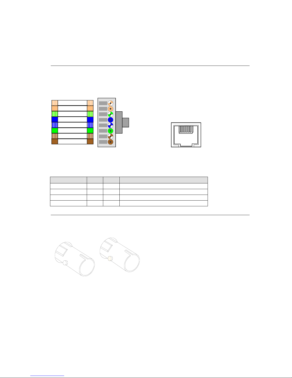
1.6 RJ-45 Ethernet Connector
The next drawing shows a typical RJ-45 connector. The color is not standard but very typical
of an Ethernet
view is from the end of the
Orange + White
Orange
Green + White
Blue
Blue + White
Green
Brown + White
Brown
Figure 2 - RJ-45 Connector
Table 1 - Ethernet Interface Signals
Signal Name DIR PIN Primary Function
TX+ Out 1 Transmit Data +
TX- Out 2 Transmit Data RX+ In 3 Differential Ethernet Receive Data +
RX- In 6 Differential Ethernet Receive Data -
Patch cable. Pin 1 is located at the top of the connector (Orange + White). The
connector.
1 8
1 - TX+
2 - TX3 - RX+
6 - RX-
View from
Connector End
Ethernet
(RJ45)
1.7 ST-Fiber Ethernet Connectors
Tx
The CoBox-FL also supports 10Mbit Ethernet through an ST-Fiber Ethernet connector.
Note: Do not attempt to connect both Ethernet ports simultaneously. If one is used, the other
is disabled.
CoBox-FL User Guide 1-7
Rx
Page 22
Introduction
13
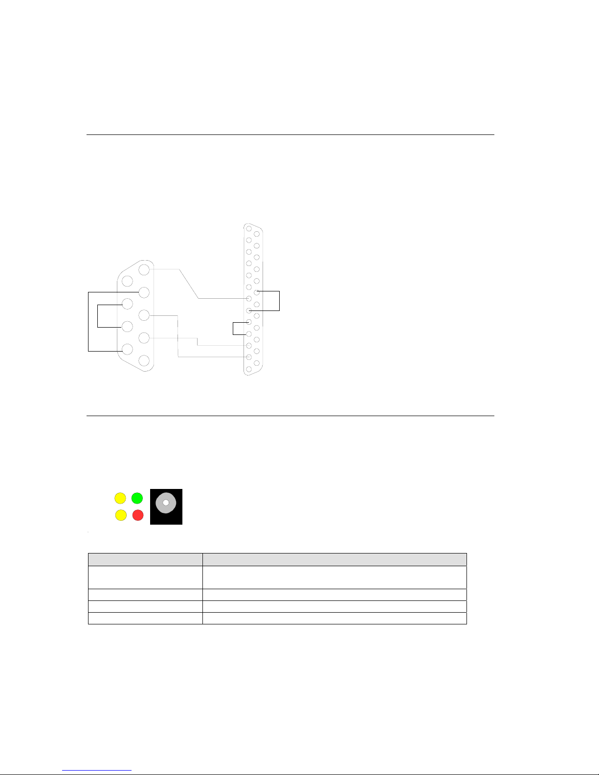
1 terface.8 Serial In Cable
The CoBox-FL can be conn l or Ethernet device for setup and configuration.
T RS l
he serial device can be -232 or RS-485/422. The following diagram shows a typica
i -2 DB-25
nterface cable for the RS 32 Serial interface. The UDS-M-SBC is an optional male
5
block con
GND
4
3
TXD
2
RXD
1
to RS-485 screw nector.
DTR
9
CTS
8
RTS
7
6
DSR
9-Pin, FEMALEDTE,
1 ork LED
.9 Netw s
ected to a seria
5
RX(in)
TX(in)
4
3
2
1
DCE, 25-Pin, MALE
25
20
6
14
The following table explains the function of the four network LEDs.
9-30V
AC/DC
Tx
GL
Rx Co
LED Meaning
GL (Good Link) rt is connected to Lights solid green to indicate network po
Tx (Network Transmit) ckets are transmitting. Blinks yellow to indicate network pa
Rx (Network Receive) rk packets are receiving. Blinks yellow to indicate netwo
Co (Collision) Blinks red to indicate network collisions.
CoBox-FL User Guide
1-8
the network.
Page 23
Introduction
1.10 Serial LEDs
Simultaneously lit red and green LEDs means something is wrong. If the red LED is lit or
blinking, count the number of times the green LED blinks betwee
indicate which fault condition exists. The following table explains
serial LEDs.
1
H
e
t
a
t
S
2
H
C
C
n its pauses. Blink patterns
the functions of the three
LEDs
Table 2 - CoBox-FL LED Functions
LED Meaning
GREEN
CH1
YELLOW
CH2
RED
Diagnostic
Lights solid green to indica
connection to or from the network
Blinks green to indicate that
from the network.
Lights solid yellow to indi
to or from the network.
Blinks yellow to indicate Channel 2 does have a connection to or
from the network.
Blinks or lights solid red in combination with the green (Channel 1)
LED to indicate diagnostics and error detection.
Red solid, g
1x: EPROM
reen (Channel 1) blinking:
checksum error
2x: RAM error
3x: Token Ring error
4x: EEPROM checksum error
5x: Duplicated IP address on the network
Red blinking, green (Channel 1) blinking:
4x: Faulty network connection
5x: No DHCP response received
te that Channel 1 does not have a
.
Channel 1 does have a connection to r
o
cate Channel 2 does not have a connection
CoBox-FL User Guide 1-9
Page 24
Introduction
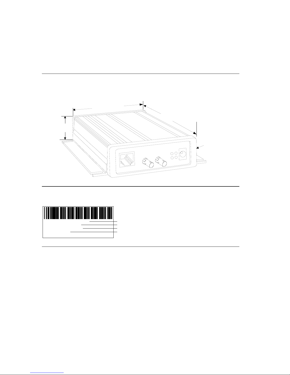
1.11 Dimensions
The CoBox-FL dimensions are shown in the following drawing.
Note: For CoBox-FL and CoBox-FL-IAP.
)4.46 in. (11.34 cm
6.5 in. (16.51 cm)
1.39 in. (3.55 cm)
30V
-
9
C
D
/
C
A
L
T
-
E
S
A
B
0
1
L
F
-
E
S
A
B
10
T
x
R
x
G
x
T
o
C
x
R
Removable Guard
1.12 Product Information Label
The product information label contains important information about your specific unit.
COBOX-FL-IAP
00-20-4A-52-68-EF
Rev. A11
Made in USA
S/N:5226863
Serial Number
Part Number
MAC ID
Revision
1.13 Software Support
DeviceInstaller is a powerful software utility for configuring device servers from a network
connection. For more information, see Using DeviceInstaller on page 3-2.
Lantronix DeviceComm Manager is a Windows based COM port redirector software utility.
Its function is to redirect customer application data destined for a local serial (COM) port to
the PC’s network port. Rather than going out the local port, the data is transmitted across the
Ethernet network port using the TCP/IP protocol. For more information, see DeviceComm
Manager on page 5-1.
CoBox-FL User Guide
1-10
Page 25
Introduction
1.14 Power Requirements
The CoBox-FL is shipped with a 12VDC, 0.8A, 100-240VAC, 50-60Hz power supply, but
VAC/DC and 30V AC/DC can be used. any power supply between 9
V
0
3
-
9
C
D
/
C
A
1
B
0
1
x
T
L
F
-
E
S
A
x
R
T
-
E
S
A
B
0
L
G
x
T
o
C
x
R
9-30V AC/DC
Power
CoBox-FL User Guide 1-11
Page 26

Introduction
1.15 Technical Specifications
Table 3 - Technical Specs
Category Description
CPU, Memory AMD 188ES CPU, 20MHz clo ck, 128kByte RAM
Flash, EPROM 512kByte Flash PROM
Installable Serial
Protocols
Serial Interface DB-25F, RS-232C or RS-4
Power Supply External adapter for 9-30V AC/DC, 3 Watts Max
Dimensions 16.51 cm (6.5 in) , 11.34 cm (4.46 in) , 3.55 cm (1.39 in)
Weight .48 kg (1.10 lbs)
Temperature Operating range: 5° to +50° C (41to122° F)
Humidity 10% to 90% RH, no n-conden sing, 40% to 60% recommended
Case Metal case with mounting flanges.
Protocols Supported Auto IP, ARP, UDP/IP, TCP/IP, Telnet, ICMP, SNMP, DHCP,
Network Interface RJ-45 10BASE-T or ST-Fiber 10BASE-FL
Serial Line Formats Characters: 7 or 8 data bits
Modem Control DTR, DCD, CTS, RTS, DSR
Flow Control CTS/RTS (hardware)
Management Internal web server (Standard Tunneling only)
System Software Windows® 95/98/ME/NT/2000 based configuration software
LEDs Network Transmit, Network Receive, Good Link, Collisions, Channel
Compatibility Ethernet: Version 2.0/IEEE 802.3
Standard Tunnel (CoBox-F
FL-IAP), DF1 (CoBox-FL-IAP)
DB-9M, RS-232C (DTE pin
Baud Rate selectable from
Max temperature change per hour: 20° C (36° F)
Storage range: -40° to +66° C (-40 to 151° F)
BOOTP, TFTP, and HTTP
Stop bits: 1,2
Parity: odd, even, none
XON/XOFF (software)
SNMP (read only)
Serial login
Telnet login
1 Status, Channel 2 Status, Diagnostic
L, and CoBox-FL-IAP), Modbus (CoBox-
22/485 (DCE pinout)
out)
300bps to 115Kbps
CoBox-FL User Guide
1-12
Page 27

Getting Started
22.. GGeettttiinngg SSttaarrtteedd
This section describes all the procedures for configuring your unit. For a short version, see
the Quick Start Guide. Go to the Lantronix web site for the latest firmware and release notes.
CoBox-FL comes with Standard Tunnel Protocol and the CoBox-FL-IAP comes with the IAP
Standard Tunnel Protocol. Both versions are similar but cannot be interchanged. Standard
Tunneling is a serial communications protocol used by most Lantronix Device Servers. It can
be configured to Ethernet-enable most serial devices such as barcode scanners, weigh scales,
operator panels, data access devices, alpha numeric displays, and thousands of intelligent
serial devices. For CoBox-FL-IAP users, see Industrial Automation Protocols on page 1-3
Loading industrial protocols to a CoBox-FL-IAP, such as IAP Modbus Bridge, may remove
the web pages and change the configure dialogs. See the user manuals on individual protocols
for protocol specific settings and configuration dialogs. Protocol manuals are found on the
software CD. This section describes the setup and configuration dialogs for the Standard
Tunnel Protocol.
Note: The following information is based on the condition that a CoBox-FL is loaded with
Standard Tunnel Protocol. The CoBox-FL-IAP with IAP Standard Tunnel Protocol may have
different options available.
2.1 Addresses and Port Number
2.1.1 Ethernet (MAC) Address
The Ethernet address is also referred to as the hardware address or the MAC address. The
first three bytes of the Ethernet Address are fixed and read 00-20-4A, identifying the unit as a
Lantronix product. The fourth, fifth, and sixth bytes are unique numbers assigned to each
unit.
00-20-4A-21-18-17 or 00:20:4A:21:18:17
2.1.2 Internet Protocol (IP) Address
Every device connected to an IP network must have a unique IP address. This address is used
to reference the specific unit.
CoBox-FL User Guide 2-1
Page 28
Getting Started
2.1.3 Port Number
Every TCP connection and every UDP datagram is defined by a destination IP address and a
port number. For example, a Telnet application commonly uses port number 23. A port
number is similar to an extension on a PBX system.
The unit 's serial channel (port) can be associated with a specific TCP/UDP port number. Port
number 9999 is reserved for access to the unit's Setup (configuration) Mode window.
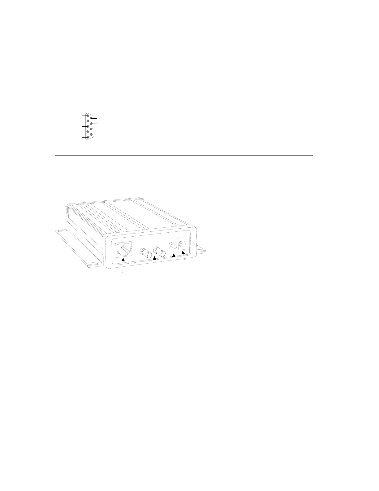
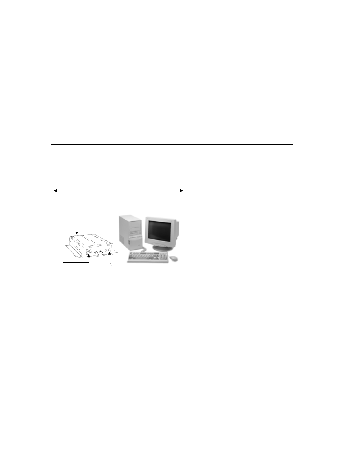
2.2 Physically Connecting the Unit
The following diagram shows a typical hardware configuration for the CoBox-FL. Use one
of the cables described in Serial Interface Cable on page 1-8 to connect a PC COM port to
the CoBox-FL.
Ethernet
RS-232
V
0
3
-
9
C
D
/
C
A
L
T
-
G
E
S
A
B
0
1
Ethernet
x
T
L
F
-
E
S
A
B
0
1
x
R
x
T
x
R
9-30V AC/DC
o
C
Figure 3 – CoBox-FL Connected to Serial Device and Network
1. Connect a serial device to your unit. See Serial Interface Cable on page 1-8 for more
information about cable and connector specifications.
2. Connect an Ethernet cable to one of the Ethernet ports.
3. Supply power to your unit using a 9-30V AC/DC source.
Note: The required input voltage is 9-30V AC/DC (3 W maximum).
4. Supply power to the serial device.
Note: Connecting a device to an active Ethernet network can disrupt communications on the
network. Make sure the device is configured for your application before connecting to an
active network.
CoBox-FL User Guide
2-2
Page 29

Getting Started
2.3 Methods of Assigning the IP Address
The unit's IP address must be configured before a network connection is available. You have
the following options for assigning an IP to your unit:
Method Description
DHCP A DHCP server automatically assigns the IP address and network
settings. See
DeviceInstaller
(Recommended)
ARP and Telnet You manually assign the IP address and other network settings at a
AutoIP This automatic method is appropriate when you have a small group of
Serial Port Login You initially configure the unit through a serial connection. See Serial
You manually assign the IP address using a graphical user interface
(GUI) on a PC attached to a network. See DeviceInstaller on page 2-5.
command prompt using a UNIX or Windows-based system. Only one
person at a time can be logged into the configuration port (port 9999).
This eliminates the possibility of several people simultaneously
attempting to configure the unit. See
hosts rather than a large network. This method allows the hosts to
negotiate with each other and assign addresses, in effect creating a
small network. See
Port Login on page 2-12.
DHCP on page 2-4.
ARP and Telnet on page 2-11.
AutoIP on page 2-4.
These methods are described in the remaining sections of this chapter.
Note: In most installations, a fixed IP address is desirable. The systems administrator
generally provides the IP address. Obtain the following information before starting to set up
your unit:
IP Address: ___ ___ ___ ___
Subnet Mask: ___ ___ ___ ___
Gateway: ___ ___ ___ ___
CoBox-FL User Guide 2-3
Page 30

Getting Started
2.3.1 DHCP
The unit ships with a default IP address of 0.0.0.0, which automatically enables DHCP.
Provided a DHCP server exists on the network, it will assign the unit an IP address, gateway
address, and subnet mask when the unit boots up. The CoBox-FL has acquired an IP address
if the red LED stops flashing and the green GL LED is on continuously. (If no DHCP server
exists, the unit responds with a diagnostic error: the red Diagnostic LED blinks continuously,
and the green GL LED blinks five times. This blinking only continues for about 5 seconds.)
You can use the DeviceInstaller software to search the network for the IP your unit has been
assigned by the DHCP server and add it to the managed list. See Add the Unit to the Manage
List later in this chapter.
Note: This DHCP address will not appear in the unit’s standard configuration screens. You
can determine your unit’s DHCP-assigned IP address from the DHCP server, or in Monitor
Mode. When you enter Monitor Mode from the serial port with network connection enabled
and issue the NC (Network Communication) command, you will see the unit’s IP
configuration.
2.3.2 AutoIP
The unit ships with a default IP address of 0.0.0.0, which automatically enables Auto IP
within the unit. AutoIP is an alternative to DHCP that allows hosts to automatically obtain an
IP address in smaller networks that may not have a DHCP server. A range of IP addresses
(from 169.254.0.1 to 169.254.255.254) has been explicitly reserved for AutoIP-enabled
devices. The range of Auto IP addresses is not to be used over the Internet.
If your unit cannot find a DHCP server, and you have not manually assigned an IP address to
it, the unit automatically selects an address from the AutoIP reserved range. Then, your unit
sends out a (ARP) request to other nodes on the same network to see whether the selected
address is being used.
• If the selected address is not in use, then the unit uses it for local subnet communication.
• If another device is using the selected IP address, the unit selects another address from the
AutoIP range and reboots itself. After reboot, the unit sends out another ARP request to see if
the selected address is in use, and so on.
AutoIP is not intended to replace DHCP. The unit will continue to look for a DHCP server on
the network. If a DHCP server is found, the unit will switch to the DHCP server-provided
address and reboot.
Note: If a DHCP server is found, but it denies the request for an IP address, the unit does not
attach to the network, but waits and retries.
AutoIP can be disabled by setting the unit’s IP address to 0.0.1.0. This setting enables DHCP
but disables AutoIP.
CoBox-FL User Guide
2-4
Page 31

Getting Started
2.4 DeviceInstaller
You can manually assign the IP address using DeviceInstaller software, which is found on the
product CD. If you want to use a serial connection instead of an Ethernet connection to
configure the device, go to Serial Port Login on page 2-12.
2.4.1 Install DeviceInstaller Software
1. Insert the product CD into your CD-ROM drive. The CD will automatically start and
display the main window.
If the CD does not launch automatically:
a) Click the Start button on the Task Bar and select Run.
b) Enter your CD drive letter, colon, backslash, deviceinstaller.exe (e.g.,
E:\deviceinstaller.exe).
Figure 4 – CD Main Window
2. Click the Device Installer button. The installation wizard window displays.
3. Respond to the installation wizard prompts. (When prompted to select an installation
type, select Typical.)
CoBox-FL User Guide 2-5
Page 32

Getting Started
2.4.2 Assign IP Address and Network Class
Click the Start button on the Task Bar and select Programs \Device Installer \Device
Installer. The Device Installer window displays.
Figure 5 - DeviceInstaller Window
1. Click the IP icon
. T ys. he Assign IP Address window displa
Figure 6 - Assign IP Address Window
2. In the Enter the Hardware or Ethernet Address field, enter the Ethernet address (MAC
address), which is listed on the label on the side of the unit.
CoBox-FL User Guide
2-6
Page 33

Getting Started
3. In the Enter IP Address to assign field, enter the unit’s IP address in
XXX.XXX.XXX.XXX format.
4. In the PC Network Class section, select the class (subnet mask). (Most users select Clas
C).
5. Click the Set IP Address button. (IP is assigned, pinged, and tested)
6. at the “Assign IP successful” message displays and click OK.
Confirm th
7. Click the Back button to return to the DeviceInstaller window.
2.4.3 Test the IP Address
1. Click the Ping icon . The Ping Device window displays.
s
Figure 7 - Ping Device Window
2. Confirm that “Reply received” messages displa
y in the window, indicating that the IP
address has been entered successfully.
Note: If you do not receive “Reply received” messages
attached to the network and that the IP address
, make sure the unit is properly
assigned is valid for the particular network
segment you are working with. If you are not sure, check with your systems administrator.
3. Click the Back button to retu
rn to the Device Installer window.
CoBox-FL User Guide 2-7
Page 34

Getting Started
2.4.4 Add the Unit to the Manage List
Now add the unit to the list of similar Lantronix devices on the network so that you can
manage and configure it.
1. Click the Search the network for devices
icon. T
he Search Network window
displays.
Figure 8 - Search Network Window
2. Select the PC Network Cla
ic
3. Cl k the Start Search button. A list of all active units displays.
4. Clic
5. Click .
k the Save button. A confirmation message displays.
OK
ss. Class C is the default.
CoBox-FL User Guide
2-8
Page 35

Getting Started
6. Click the Back button to re
window now lists all of the
turn to the DeviceInstaller window. The DeviceInstaller
devices in the group, including the unit you are setting up.
The hardware address and firmware release number for the unit display.
ure 9 - Devices in a Group
Fig
you can manage (configure) the unit so that it works with the serial device on the
Now
ork.
netw
CoBox-FL User Guide 2-9
Page 36

Getting Started
2.4.5 Opening a Configuration Window
1. Click the Manage icon . The Device Management window displays.
Figure 10 - Device Management Window
2. Do one of the following:
Note: To assign Expert settings and Security settings, you must use the Setup Mode window
in a Telnet session.
• To configure the unit via a Web browser, click the Web Configuration icon
The Lantronix Web-Manager window displays in your browser. For Web
Configuration, see Web Manager Page on page 3-4.
• To configure the unit via a Telnet session, click the Telnet to Device icon
.
The Setup Mode window displays. For Telnet Configuration, see Using a Telnet
Connection on page 3-10
3. Continue with the appropriate configuration procedure described in the next chapter.
Note: The Get Configuration icon on the Device Management window allows you to save a
configuration locally on your computer as a file. The Set Configuration icon sends a saved
file to the unit.
To Get Configuration information see Get Configuration on page 3-26. To Set
Configuration of a specific device see Set Configuration on page 3-27.
CoBox-FL User Guide
2-10
.
Page 37

Getting Started
2.5 ARP and Telnet
The unit’s IP address must be configured before a network connection is available. You are
able to ARP an address into a CoBox/UDS device even if there is already an address in the
unit. If the unit has no IP address, you can use Address Resolution Protocol (ARP) method
from UNIX and Windows-based systems to assign a temporary IP address. If you want to
initially configure the unit through the network, follow these steps:
1. On a UNIX or Windows-based host, create an entry in the host's ARP table using the
inten n the product
ded IP address and the hardware address of the unit, which is found o
label on the bottom of the unit. Some UNIX hosts use colons “:” betwe
octets, and some use dashes “-“. All Windows hosts use dashes.
arp -s 191.12.3.77 00:20:4a:xx:xx:xx
Note: For the ARP command to work on Windows 95, the ARP table on the PC must have at
least one IP address defined other than its own.
2. If you are using Windows 95, type ARP -A at the DOS command prompt to verify that
there is at least one entry in the ARP table. If the local machine is the only entry, ping
another IP address on your network to build a new entry in the ARP table;
must be a host other than the machine on which you are working. Once there is at least
one additional entry in the ARP table, use the fo
llowing command to ARP an IP address
to the unit:
arp -s 191.12.3.77 00-20-4a-xx-xx-xx
3. Open a Telnet connection to port 1. The connection will fail quickly, but the unit will
temporarily change its IP address to the one designated in this step.
telnet 191.12.3.77 1
4. Finally, open a Telnet connection t
into Setup Mode. If you wait longe
o port 9999, and press Enter within three seconds to go
r than three seconds, the unit will reboot and you will
need to perform step 3 again.
telnet 191.12.3.77 9999
5. Set all required parameters
Note: The IP address you just set is temporary and will revert to the defau value when th
unit 's power is reset unless you log into the unit and store the changes per anently. Refe
chapter on configuration for the instructions on permanently configuring t
en hardware
the IP address
lt e
m r to
he IP address.
CoBox-FL User Guide 2-11
Page 38

Getting Started
2.6 Serial Port Login
If you want to initially configure the unit through a serial connection, follow these steps:
1. Connect a console terminal or PC running a terminal emulation program to your unit's
serial port. The default serial port settings are 9600 baud, 8 bits, no parity, 1 stop bit, no
flow control.
2. To enter Setup Mode, cycle the unit's power (power off and back on). After power-up
the self-test begins and the red Diagnostic LED starts blinking. You have one second
enter three lowercase x characters.
ode is to holNote: The easiest way to enter Setup M
d down the x key at the terminal (or
emulation) while powering up the unit.
3. At this point, the screen display is the same as when you use a Telnet connectio
continue with a serial port login, go to Using a Telnet Connection on page 3-1
0.
,
to
n. To
CoBox-FL User Guide
2-12
Page 39

Configure
33.. CCoonnffiigguurriinngg tthhee UUnniitt
You must configure the unit so that it can communicate on a network with your serial device.
For example, you must set the way the unit will respond to serial and network traffic, how it
will handle serial packets, and when to start or close a connection. You can configure yo
unit locally or remotely using the following procedures:
• Use a standard Web browser to access the unit’s internal Web pages and configure
the unit over the network. This is the easiest and preferred method.
• Use a Telnet connection to configure the unit over the network.
• Use a terminal or terminal emulation program to access the serial port locally.
The unit’s configuration is stored in nonvolatile memory (NVRam) and is retained without
power. You can change the configuration at any time. The unit performs a reset after the
configuration has been changed and stored.
Note: The configuration menus in this section show a typical device and all of the possible
configuration options. Your device may have different configuration options.
ur
3.1 Configuring via Web Browser
Open your JAVA enabled web browser and enter the IP address. The Lantronix Web
Manager page will display. Go to Web Manager Page for a summary of the menu selections.
Note: The CoBox-FL-IAP may not have a web page or may use a different format web page.
CoBox-FL User Guide 3-1
Page 40

Configure
3.2 Using DeviceInstaller
DeviceInstaller is a powerful software utility for configuring device servers from a network
connection. This section uses the utility to demonstrate the various methods of configuring
device. The Devica e Management window is a common page for gaining access to different
menus.
1 Start DeviceInstaller. Click the Search for network for devices icon
.
. The Search
Network window displays.
2. Click the Start Search button. A list of all active units displays.
3. Click the Save button. Click OK for the confirmation message. Click the Back button.
4. Click the Manage device configuration icon
to open the Device Management
window.
5. For Web configuration, click the Web Configuration icon to start your browser. (A
small Web Configuration window appears, showing the IP address.)
Go to Web Manager Page on page 3-4 for a summary of the menu s
Note: If your unit a
can log into it usin
lready has an IP address (see Methods of Assigning the IP Address), you
g a standard Web browser that is Java enabled. Type the unit's IP address
into the Web browser's URL (Address/Location) field.
CoBox-FL User Guide
3-2
elections.
Page 41

Configure
6. For Telnet configuration, click the Telnet to Device icon. A small Telnet to Device
window appears, showing the IP Address and the Port address. The main Lantronix
Universal Device Serve
r window opens.
Go to Using a Telnet Connection on page 3-10 for a summary of the menu selections.
7. To Get device configuration information see Get Confi
guration on page 3-26.
Configuration information can be read from a device and saved
8. To Set the configurati
A device can
be configured by reading a configuration file and sending the information to the
on of a specific device see Set Configuration on page 3-27
device.
in a file.
CoBox-FL User Guide 3-3
Page 42

Configure
3.3 Web Manager Page
Note: The CoBox-FL-IAP may not have a web page or may use a different format web page.
You can start a web browser for configuration by opening your JAVA enabled web browser
and entering the IP address or by clicking the Web Configuration
Management window. The Lantronix Web Manager page will display.
button on the Device
Figure 11 - Lantronix We
Web Manager 3.0 has the f
• Unit Configuration
• Server Properties
• Port Properties
• Factory Settings1
• Update Settings
• Channel 1 (also Channel 2 for devices with two serial channels
• Tech Support
• FTP – Site
• Back to Web-Manager
• Contact Us
1. Use the menu (pushbuttons) to na
settings. See explanations of the
2. When you are finished, click the Update Settings button to sav
CoBox-FL User Guide
3-4
b-Manager
ollowing buttons:
(also Factory Settings2 for devices with two serial channels)
)
vigate to sub pages where you can configure server
configuration parameters later in this chapter.
e your settings.
Page 43

Configure
3.3.1 Unit Configuration
Click the Unit Configuration button to display the following dialog box. This page contain
the Server Configuration and the Port Configuration settings. These are static settings read
from the device.
Note: The following screen shots represent the web page shown whs en the device is loaded
with cbxw300.cob firmware.
CoBox-FL User Guide 3-5
Page 44

Configure
3.3.2 Server Properties
You can change the server properties by editing any of the fields. Lingering over one of the
fields w s will require you to enter the
new IP
ill display operator messages. Changing the IP addres
address in the browser to reload the page.
Fig re
u
12 - Server Properties Configuration on the Web Browser
Te net Password
l
In the Telnet Password field, enter a password to prevent unauthorized access to the Setup
Mode via a Telnet connection to port 9999. The password is limited to 4 characters. (An
enhanced password setting of 16 characters is available under Security Settings on the Tel
Setup Mode window.)
Note: No password is required to access the Setup Mode window via a serial connection.
CoBox-FL User Guide
3-6
net
Page 45

3.3.3 Port Properties
Serial Protocol: RS232, RS422/485 4-wire, RS485 2-wire
Speed: 1 , 57600, 115200
Character Si
Parity: N
Stop Bi
Flow Co acters to Host, CTS/RTS
(Hardw
200, 2400, 4800, 9600, 19200, 38400
ze: 8, 7
one, Even, Odd
t: 1,2
ntrol: None, XON/XOFF, XON/XOFF Pass Char
are)
Configure
UDP Datagram Mode: Enable, Disable
UDP Datagram Type: (User selectable)
Incoming Connection: Accept unconditional, Accept Incoming/DTR (Inactive), Never accept
incoming
Response: Nothing (quiet), Character response
Startup: No active startup, with any character, with active DTR (Inactive), with CR (0x0D)
only, Manual Connection, Autostart, Modem Mode
Remote IP Address: (user selectable)
Remote Port: (user selectable)
Local Port: 10001 (default 10001, user selectable)
CoBox-FL User Guide 3-7
Page 46

Configure
On Active Connection: Enable, Disable
On Passive Connection: Enable, Disable
At Time of Disconnect: Enable, Disable
Packing Algorithm: Enable, Disable
Idle Time: Force transmit 12 ms, Force transmit 52 ms, Force Transmit 250 ms, Force
Transmit 5000 ms
Trailing Characters: None, One, Two
Send Immediate After Sendchars: Enable, Disable
Send Define2-Byte Sequence: Enable, Disable
Send Character 01: (User Selectable)
Send Character 02: (User Selectable)
CoBox-FL User Guide
3-8
Page 47

Disconnect Mode: with DTR Drop, Ignore DTR
C to na
heck for CTRL-D
P ble
ort Password: Ena
T et Mode: Enable, D le
eln isab
Disconnect: E
, Disable
ble, Disable
Inactivity Timeout: Enable, Disable
Inactivity Timer: (User
Selectable)
Port Password: (User Selectable. Port Password must be enabled)
Configure
3.3.4 Technical Support
Several buttons provi
S ink dire ntronix Tech Support web page, the FTP-Site button
upport button to l
w eb pag r downloading new firmware, manuals, and other files. The
ill link you to the w e fo
C ill link u to the Contact Information page.
ontact Us button w yo
3 ttings
.3.5 Update Se
C ttings button to send all changed settings to the device.
lick the Update Se
de dir ons. You can use the Tech
ect links to Technical Support functi
ctly to the La
CoBox-FL User Guide 3-9
Page 48

Configure
3.4 Configuring via the Setup Mode Window
3.4.1 Using a Telnet Connection
To configure the unit over the network, establish a Telnet connection to port 9999.
Note: If you use the Telnet to Device icon on the Device Installer Device Management
window OR a serial port lo
1. From the Windows Start menu, click Run and type the followin
x.x.x.x is the IP address and 9999 is the unit’s fixed network co
telnet x.x.x.x 9999
Note: Be sure to include a space between the IP address and 9999.
2. Click OK.
3. The Lantronix Universal Device Server window displays.
*** Lantronix Universal Device Server ***
Serial Number 7218033 MAC address 00:20:4A:72:46:71
Software version 04.5 (011025)
ess Enter to go into SetuPr p Mode
4. To enter the Setup Mode, you must press Enter within 5
sett ode Window.
ings will appear. See Figure 13 - Setup M
Note: The following line appears only with IAP Standard Tunnel Protocol Firmware.
Model: Device Server Plus+! (Firmware Code: AQ)
5. Select an option on the menu by entering the number of the option in the Your choice
field and pressing Enter.
6. To enter a value for a parameter, ty
value, just press Enter.
7. When you are finished, save the new configurations (option 9). The unit will reboot.
gin to establish the connection, skip steps 1and 2.
g command, where
nfiguration port number.
seconds. The configuration
?
pe the value and press Enter, or to confirm a current
CoBox-FL User Guide
3-10
Page 49

*** basic parameters
Hardware: Ethernet Autodetect
IP addr – 0.0.0.0/DHCP/BOOTP/AutoIP, no gateway set
DHCP device name : not set
*****************
SNMP is
SNMP Community
Telnet Setup is
TFPT Download is
Port 77Feh is enabled
Web Server is enabled
Enhanced password is
***************** Chann
Baudrate 9600, I/F Mode
Port 10001
Remote IP Adr: --Co
nnect Mode : C0 Disconn Mode: 00
Flush Mod
****************** Expert *******************
TCP Keepalive : 0s (not IAP firmware)
Change Setup :0 Server configuratio
1 Channel 1 configuration
5 Expe
6 Secu
7 Factory defaults
8 Exit without save
9 Save and exit
e : 00
Security *****************
enabled (not IAP firmware)
Name: (not IAP firmware)
enabled
enabled
disabled
el 1 *****************
4C, Flow 00
none ---, Port 00000
n
rt settings (not IAP firmware)
rity
Your choice ?
Configure
Figure 13 - Setup Mode Window
CoBox-FL User Guide 3-11
Page 50

Configure
3.4.2 Using the Serial Port
If you want to initially configure the unit through a serial connection, follow these steps:
8. Connect a console terminal o terminal ram to
serial port. The default serial port se re 9600 baud parity
r PC running a emulation prog your unit's
ttings a , 8 bits, no , 1 stop bit, no
flow control.
9. To enter Setup Mode, cycle the unit's pow r (power off a ). Af
the self-test begins and the red Diag ED starts bli
e nd back on ter power-up,
nostic L nking. You have one second to
enter three lowercase x characters (xxx).
Note: The easiest way to enter Setup Mode is to hold down the x key at the ter
emulation) while powering
up the unit.
10. At this point, the screen display is the same as when you use a Telnet connection
continue with a serial port login, go to Using a Telnet Connection on page 3
minal (or
. To
-10.
3.5 Server Configuration (Network Configuration)
T s basic network parameters. The following parameters are displayed when
hese are the unit’
y ation.
ou select Server configur
IP Address : (000) .(000) )
Set Gateway IP Address (N)
Netmask: Numbe
Change telnet
r of Bits for Host Part (0=default) (00)
config password (N)
.(000) .(000
3.5.1 IP Address
he IP address must be set to a unique value in your network. See T
IP Address on page for more inform
3.5.2 Set Gateway
T ress, o s communication to other LAN segments. The gateway
he gateway add r router, allow
2-3 ation about IP addressing.
IP Address
address should be the IP address of the router connected to the same LAN segment as the
unit. The gateway addr
CoBox-FL User Guide
3-12
ess must be within the local network.
Methods of Assigning the
Page 51

3.5.3 Netmask: Number of Bits for Host Part
Configure
A netmask defines the number of bits taken from the IP address that are assigned for the
section.
Note: Class A: 24 bits; Class B: 16 bits; Class C: 8 bits.
The unit prompts for the number of
is displayed in standard decim
host bits to be entered, then calculates the netmask, which
al-dot notation hen e s d p me are disp ed (for
w th ave ara ters lay
example, 255.255.255.0).
Table 4 - Standard IP Ne
twork Netmasks
Network Class Host Bits Netm sk a
A 24 255.0.0.0
B 16 255.255.0.0
C 8 255.2 5.255.0 5
Table 5 - Netmask Examples
Netmask Host Bits
255.255.255.252 2
255.255.255.248 3
255.255.255.240 4
255.255.255.224 5
255.255.255.192 6
255.255.255.128 7
255.255.255.0 8
255.255.254.0 9
255.255.252.0 10
255.255.248.0 11
... ...
255.128.0.0 23
255.0.0.0 24
host
CoBox-FL User Guide 3-13
Page 52

Configure
3.5.4 Change Telnet configuration password
S g ia
etting the Telnet confi uration password prevents unauthorized access of the setup menu v
a ion to po
Telnet connect
A ssword s
hanced pa
a
ccess only.
rt 9999 or via Web pages. The password is limited to 4 characters.
under Security Settings for Telnet n en etting of 16 characters is available
Note: No password is required to access the Setup Mode window via a serial connection.
3.5.5 DHCP Naming
There are 3 methods for assigning DHCP names to th
ese products.
1) Default DHCP name. If you do not change the DHCP name, and you are using an IP of
0.0.0.0, then the DHCP name will default
to CXXXXXX (XXXXXX is the last 6 digits of the
MAC address shown on the label on the bottom/side of the unit). For example, if the MAC
address is 00-20-4A-12-34-56, then the default DHCP name is C123456.
2) Custom DHCP nam
e. You can create your own DHCP name on these products. If you are
using an IP address of 0.0.0.0, then the last option in "Server configuration" will be "Chan
DHCP device name". The "Change DHCP device name" option will allow you to change
DHCP name to an alpha numeric name.
Change DHCP device name (not set) ? (N) Y
Enter new DHCP device name : LTX
3) Numeric DHCP name. You are able to change the DHCP name by specifying the last
octet of the IP address. When you use this method, t
YY is what you chose for the last octet of the IP address. If the IP address you specify
he DHCP name will be LTXYY where
is
0.0.0.12, then the DHCP name will be LTX12. This method will only work with 2 digit
numbers (0-99).
ge
the
CoBox-FL User Guide
3-14
Page 53

3.6 Channel 1 Co ion (Serial Port Parameters) nfigurat
Configure
Using this option, defin
e
how the serial port will respond to network and serial
communications.
Baudrate (960
de (4C)
Flow (00)
No (1000
Port
ctMode (
Conne
Remote IP Add
Remote Port (
DisConnMode (
Mode (
Flush
nnTime (
DisCo
SendChar 1 (
SendChar 2 (
0)
I/F Mo
1)
C0)
ress : (000).(000).(000).(000)
00000)
00)
00)
00:00) :
00)
00)
3.6.1 Baudrate
The unit and attached se
use for the serial connec
19200, 38400, 57600, an second.
3.6.2 I/ Mode
F (Interface)
The Interface (I/F) Mod al notation.
e Table 35 - Bin
rial device, such as a modem, must agree on a speed or baud rate to
es are 300, 600, 1200, 2400, 4800, 9600 (default), tion. Valid baud rat
d 115200 bits per
e is a bit-coded byte that you enter in hexadecim
e. Note: Se ary to Hexadecimal Conversion Tabl
Table 6 - Interface Mod
I/F Mode Option 7 6 5 4 3 2 1 0
RS-232C
RS-422/485
RS-485 2-wire
(1)
(1)
(1)
e Options
0 0
0 1
1 1
7 Bit 1 0
8 Bit 1 1
No Parity 0 0
Even Parity 1 1
Odd Parity 0 1
1 Stop bit 0 1
2 Stop bit 1 1
(1) The CoBox-FL requires you to choose the correct setting in the IF mode, and to also set
the front-panel switch for selection of RS-232/RS-485.
CoBox-FL User Guide 3-15
Page 54

Configure
The following table demonstrates how to build som
Table 7 - Common Interface Mod
e Settings
e common Interface Mode settings:
Common I/F Mode Setting Binary Hex
RS-232C, 8-bit, No Parity, 1 stop bit
RS-232C, 7-bit, Even Parity, 1 stop bit
RS-485 2-Wire, 8-bit, No Parity, 1 stop bit
RS-422, 8-bit, Odd Parity, 1 stop bit
(1)
(1)
(1)
0100 1100 4C
0111 1000 78
(1)
0100 1111 4F
0101 1101 5D
(1) The CoBox-FL requires you to choose the correct setting in the IF mode.
3.6.3 Flow
Flow control sets the local handshake method for stopping serial input/output.
Table 8 - Flow Control Options
Flow Control Option He x
No flow control 00
XON/XOFF flow control 01
Hardware handshake with RTS/ S s 02CT line
XON/XOFF pass characters to h st 05o
3.6.4 Port Number
The setting represents the source port numb r in TCP connections, and is the number used to
identify the channel for remote initiating connections ef lt s ttin r Port 1 is 10001.
R ol wi re e po numbers:
ange: 0-65535 except for the f lo ng serv d rt
e
. D au e g fo
Port Numbers Reserved for
1 – 1024 Reserved (well known ports)
9999 Telnet setup
14000-14009 Reserved
30718 Reserved (77FEh)
10000-10999
Recommended ports, should be used for DeviceComm
Manager (COM1-COM256) or direct socket connections
The port number functions as the TCP/UDP source port number for outgoing packets.
Packets sent to the unit with this port number are received to this channel. The port number
selected is the Incoming TCP/UDP port and Outgoing TCP/UDP source port. Port 0 is used
when you want the outgoing source port to change with each connection.
CoBox-FL User Guide
3-16
Page 55

Configure
3.6.5 Connect Mode
Connect Mode defines how the unit makes a connection, and how it reacts to incoming
connections over the network. Enter Connect Mode options in hexadecimal notation.
Note: See Table 35 - Binary to Hexadecimal Conversion Table.
Table 9 - Connect Mode Options
Connect Mode Option 7 6 5 4 3 2 1 0
Incoming Connection
Never accept incoming 0 0 0
Accept incoming with DTR 0 0 1
Accept unconditional 1 0 1
Response
Nothing (quiet) 0
Character response (C=connect,
D=disconnect, N=unreachable)
Startup
No active startup 0 0 0 0
With any character 0 1 0 0
With active DTR
With CR (0x0D) only 1 1 0 0
Manual connection 0 1 0 0
Autostart 0 1 0 1
Datagram Type
Directed UDP 1 1 0 0
Modem Mode
Full Verbose 1 0 1 1 0
Without Echo 0 0 1 1 0
1-character Response 1 0 1 1 1
(1)
1
0 0 1 0
Manual Connection: When you use manual connection, you are not required to enter the
entire IP address if the IP is already configured as the remote IP address in the unit. For
example, if the remote IP address already configured in the unit is 129.1.2.3, then an example
command string would be C3/7. (This would connect to 129.1.2.3 and port 7.) You may also
use a different ending for the connection string. For example, C50.1/23 would connect you to
129.1.50.1 and port 23.
CoBox-FL User Guide 3-17
Page 56

Configure
Table 10 - Manual Connection Address Example
Command String Result if remote IP is 129.1.2.3 and remote port is 1234
C121.2.4.5/1 Complete override; connection is started with host 121.2.4.5, port 1
C5 Connect to 129.1.2.5, port 1234
C28.10/12 Connect to 129.1.28.10, port 12
Autostart (Automatic Connection): If autostart is enabled, the unit automatically connects
to the remote IP address and remote port specified.
Datagram Type: When selecting this option, you will be prompt
Enter 01 for directed or broadcast U
M mulation) Mode: M e o t n r t modem interface to the
odem (E In od m M de, he u it p esen s a
a l device. It accepts AT-style modem commands, and handles the modem signals
ttached seria
c
orrectly.
N em c ne ed a l al a a e onnected to a remote
ormally there is a mod on ct to oc PC nd mod m c
m l from the local PC o th re ote chine, accumulating phone
achine. A user must dia
c on. od Mode low yo to a odems with device
harges for each conne M em al s u
cti
servers, and to use an Ethernet connection instead of ho a ng to change
c tions and make potentially expensive phone calls.
ommunications applica
To select Modem Mode, set t e C ne M e t 6 e ho) (echo with full verbose),
o echo with 1-character sp se)
r D7 (
reononct.
Note: If the unit is in Modem Mode and the accept
DP.
t e m ma
repl
a p
h
od o C (no c , D6
serial port is idle, the unit can still
ed for the Datagram type.
ce m
ne c
ll, without havi
network TCP connections to the serial port if Connect Mode is set to C6 (no echo), D6 (echo
with full verbose), or D7 (echo with 1-character response).
I ers o th ech f ll of the characters entered in command mode; it
n Modem Mode, echo ref
d to echo data that is transferred. Quiet Mode (no echo) refers to the modem not
oes not mean
ending an answer to the commands received (or displaying what was typed).
s
t e o o a
To disconnect a connection using Modem Mode commands:
• There must be 1-second guardtime (no data traffic) before sending +++.
• There must not be a break longer that 1 second between +s.
• There must be another 1-second guardtime after the l
ast + is sent.
• The unit acknowledges with an OK to indicate that it is in command mode.
• Enter ATH and press Enter. It is echoed if echo is enabled. ATH is acknowledge
d
by another OK.
CoBox-FL User Guide
3-18
Page 57

Table 11 - Modem Mode Commands
Configure
Modem Mode
Function
Command
ATDTx.x.x.x,pppp or
ATDTx.x.x.x/pppp
ATDTx.x.x.x
ATD0.0.0.0
ATD
ATDx.x.x.x
ATH Hangs up the connection (Entered as +++ATH ).
ATS0=n
ATEn
ATVn
Makes a connection to an IP address (x.x.x.x) and a remote port
number (pppp).
Makes a connection to an IP address (x.x.x.x) and the remot
number def
Forces the unit into monitor mode if a remote IP address and port
number are defined within the
Forces the unit into monitor mode if a remote IP address and po
number are not defined within the unit.
Makes a connection to an IP address (x.x.x.x) and the remote port
number defined within the unit.
Enables
port.
n=0 disables the ability to make a connection from the netwo
the serial port.
n=1-9 enables the ability to make a connection from the network
to the serial port.
n>1-9 is invalid.
Enables or disables character echo and response s.
n=0 disables character echo and responses.
n=1 enables character echo and response s.
Enables 1-character response or full verbose.
n=0 enables 1-character response.
n=1 enables full verbose.
ined within the unit.
unit.
or disables connections from the network going to the serial
e port
rt
rk to
Note: These AT commands are only recognized as single commands like ATE0 or ATV1;
compound commands such as ATE0V1 are not recognized. All other AT commands with
Modem Mode set to full verbose acknowledge with an OK, but no action is taken.
CoBox-FL User Guide 3-19
Page 58

Configure
3.6.6 Remote IP Address
This is the destination IP address used with an outgoing connection.
3.6.7 Remote Port
The rem . This
parameter defines the port pted.
Note: T poses, use the
remote port number 23 (Internet standa
ote TCP port number must be set for the unit to make outgoing connections
number on the target host to which a connection is attem
o connect an ASCII terminal to a host using the unit for login pur
rd port number for Telnet services).
3.6.8 DisConnMode
Note: See Table 35 - Binary to Hexadecimal Conversion Table.
Table 12 - Disconnect Mode Options
Disconnect Mode Option 7 6 5 4 3 2 1 0
Disconnect with DTR drop
Ignore DTR 0
Telnet mode and terminal
type setup
(1)
Channel (port) password
Hard disconnect
(3)
0
Disabl 1 e hard disconnect
State L
(4)
ED off with connection
Discon nect with EOT (^D)
1. The CoBox will send the "Termina
2. A password is required for a conne
3. The TCP connection will close even if the remote site does not acknowledg
4. When there is a network connection to or from the serial port, the state LED
5. When Ctrl D or Hex 04 are detected, the connection is dropped. Both Telnet mode and Disconnect with EOT must be
for Disconnect with EOT to function properly. Ctrl D will only be detected going from the serial port to the network.
6. When DTR on the CoBox/UDS product transitions
the serial port will drop.
(6)
1
1
(2)
1
1
(5)
1
l Type" upon an outgoing connection.
ction to the serial port from the network.
e the disconnection.
will turn off instead of blink.
from a high state to a low state, then the network connection to or from
enabled
CoBox-FL User Guide
3-20
Page 59

3.6.9 Flush Mode (Buffer Flushing)
Configure
Using this parameter, you can control line handling and network buffers with connect
startup and disconnect. You can also select between two different packing algorithms.
Note: See Table 35 - Bi
nary to Hexadecimal Conversion Table.
Table 13 - Flush Mode Options
Function 7 6 5 4 3 2 1 0
Input Buffer (Serial to Network)
Clear with a connection that is initiated from
the UDS to the network
Clear with a connection initiated from t
network to the UDS
Clear when the network connection to or from
the UDS is disconnected
Output Buffer (Network to Serial)
Clear with a connection that is initiated from
the UDS to the network
Clear with a connection initiated from the
network to the UDS
Clear when the network connection to or from
the UDS is disconnected
Alternate Packing Algorithm (Pack Control)
Enable 1
he
1
1
1
1
1
1
ion
CoBox-FL User Guide 3-21
Page 60

Configure
3.6.10 Pack Control
Two firmware-selectable packing algorithms define how and when packets are sent to the
network. The standard algorithm is optimized for applications in which the unit is used in a
local environment, allowing for very small delays for single characters while keeping the
packet count low. The alternate packing algorithm minimizes the packet count on the network
and is especially useful in applicatio
parameters in this mode can economize the network data stream.
ns in a routed Wide Area Network (WAN). Adjusting
Pack control settings are enabled in Flush Mode. Set this value to 00 if specific function
not needed.
Note: See Table 35 - Binary to Hexadecimal Conversion Table.
Table 14 - Pack Control Options
Option 7 6 5 4 3 2 1 0
Idle Time
Force transmit: 12ms 0 0
Force transmit: 52ms 0 1
Force transmit: 250ms 1 0
Force transmit: 5sec 1 1
Trailing Characters
None 0 0
One 0 1
Two 1 0
Send Characters
2-Byte Send Character
Sequence
Send Immediately After
Send chars
1
1
s are
Idle Time: Idle time to "Force transmit" defines how long the unit should wait before
sending accumulated characters. This wait period is between characters. If there is an idle
period between characters equal to the force transmit set, then the unit will package up the
serial data currently in the buffer and send it to the network.
Trailing Characters: In some applications, CRC, Checksum, or other trailing characters
follow the end-of-sequence character; this option helps to adapt frame transmission to the
frame boundary.
CoBox-FL User Guide
3-22
Page 61

Configure
Send Characters: If 2-Byte Send Character Sequence is enabled, the unit interprets the
sendchars as a 2-byte sequence; if not set, they are interpreted indepen
dently.
If Send Immediately After Characters is not set, any characters alrea
are included in the transmission after a "transmit" condition is found. If set, the unit sends
immediately after recognizing the t
Note: A transmission might occur if status information needs to be exchanged or an
acknowledgment needs to be sent.
ransmit condition (sendchar or timeout).
dy in the serial buffer
3.6.11 DisConnTime (Inactivity Timeout)
Use this parameter to set an inactivity timeout. The connection is dropped if there is no
activity on the serial line before the set time expires. Enter time in the following format:
mm:ss, where m is the number of minutes and s is the number of seconds. To disable the
inactivity timeout, enter 00:00.
3.6.12 Send Characters
You can enter up to two characters in hexadecimal representation in the parameters
"sendchar." If a character received on the serial line matches one of these characters, it is
immediately, along with any awaiting characters, to the TCP connection. This minimizes
response time for specific protocol characters on the serial
etc.). Setting the first sendchar to 00 disables the recognition of the characters. Alternatively,
the two characters can be interpreted as a sequence (
line (for example, ETX, EOT,
see Pack Control on page 3-22).
sent
the
3.6.13 Telnet Terminal Type
This parameter appears only if the terminal type option is enabled in Disconnect Mode (see
DisConnMode on page 3-20 above). If this option is enabled, you can use the termin
for the Telnet terminal type. Enter only one name.
al name
If the terminal type option is enabled, the unit also reacts to the EOR (end of record) and
binary o
ptions, which can be used for applications like terminal emulation to IBM hosts.
3.6.14 Channel (Port) Passw
This param
Mode (see D
CoBox-FL User Guide 3-23
eter po assword option is enabled in Disconnect
appears only if the channel (
isC 20). If set, you can set a password on the serial port.
onnMode on page 3-
ord
rt) p
Page 62

Configure
3.7 Expert Settings
Note: You can change these settings via Telnet or serial connections only, not on the WebManager.
Note: The Expert Settings option does not appear with CoBox-FL-IAP.
These parameters should only be changed if you are an expert
and definitely know the consequences the changes might have.
TCP Keepalive time in s (1s – 65s; 0s=
disable): (0)
3.7.1 TCP Keepalive tim
e in s
This option allows you to change how many seconds the unit will wait during a silent
connection before attempting to see if the currently c ected network device is still on t
onn he
network. If the unit then gets no response, it will drop that connection.
3.8 Security Settings
Note: You can change these settings via Telnet or
Manager. We recommend that you set security over the dedicated network or over the seria
setup. If you set parameters over the network (Telnet 9999), so
settings.
Disable SNMP (N) (Not with IAP)
SNMP Community Name (public): (Not with IAP)
Disable Telnet Setup (N)
Disable TFTP Firmware Update (N)
Disable Port 77FEh (N)
Disable Web Server (N)
Enable Enhanced Password (N)
3.8.1 Disable SNMP
Note: This option does not appear with CoBox-FL-IAP.
This setting allows you to disable the SNMP protocol on the unit for security reasons.
serial connections only, not on the Web-
meone else could capture these
l
3.8.2 SNMP Community Name
Note: This option does not appear with CoBox-FL-IAP.
This option allows you to change the SNMP Community Name on the unit. This allows for
ease of management, and possibly some security. If someone tries to violate security but
doesn’t know what community to
community information from the unit.
CoBox-FL User Guide
3-24
connect to, that person will be unable to get the SNMP
Page 63

Configure
3.8.3 Disable Telnet Setup
This setting defaults to the N (No) option. The Y (Yes) option disables access to this
Configuration Menu by Telnet (port 9999). It only allows access via the Web pages and the
serial port of the unit.
3.8.4 Disable TFTP Firmware Upgrade
This setting defaults to the N (No) option. The Y (Yes) option disables the use of TFTP to
perform network firmware upgrades. With this option, firmware upgrades can be performed
only by using a *.hex file over the serial port of the unit.
3.8.5 Disable Port 77FE (H
Port 77FE is a setting that allows DeviceInstaller, Web Pages, and custom programs to
con
figure the unit remotely. You may wish to disable this capability for security purposes.
For out remote configuration, see the Lantronix Embedded Integration
more information ab
Kit user guide on the Lantronix Web site
The les remote configuration. You can
default setting is the N (No) option, which enab
configure the unit by using DeviceInstaller, Web pages, Telnet, or serial configuration. The Y
s) option disables remote configuration and Web pages.
(Ye
Note: The Yes option
including the em
disables many of the GUI tools for configuring the Device Server,
bedded Web Page Configuration tool.
ex)
www.lantronix.com.
3.8.6 Disable Web Server
This setting defaults to the N (option). The Y (Yes) option disables the use of the Web Pa
Config
3.8.7 Enable Enhanced Passw
This setting defaults to the N (option), which allows you to set a 4-character password that
protects the Configuration Menu via Telnet and Web pages. The Y (Yes) option allows you
to s et access.
uration tool that is built into the unit.
ord
et an extended security password of 16-characters for protecting Teln
ge
3.9 Factory Defaults
Select 7 to reset the unit’s Channel 1 and Enhanced Security to the factory default settings.
The server configurations (IP address information) remain unchanged.
CoBox-FL User Guide 3-25
Page 64

Configure
3.10 Exit Configuration Mode
Select 8 to exit the configuration mode without saving any changes or rebooting. Select 9 to
save all changes and reboot the device. All values are stored in nonvolatile memo
ry.
3.11 Get Configurati
The device configuration information is stored in flash memory and can be
a configuration file (filename.cfg). To get the configuration information, cl
Configuration icon button on the Device Management window. The following dialog app
The Device IP Address is shown in the first field. This is the device selected in the
DeviceInstaller main window. In the Configuration File field, click the Open File button to
select a filename for the configuration file. Click the Get button and the file information is
e and saved in the selected file. read from the devic
on
read and saved in
ick the Get
ears.
CoBox-FL User Guide
3-26
Page 65

Configure
3.12 Set Configuration
Devic can be saved in a file and later used to set the configuration
e
configuration information
of one or several devices. To set the configuration of a device from a saved file, click
Configurat
ion button on the Device Management window. The following dialog appears.
The Device IP Address is shown in the first field. This is the device selected in the
DeviceInstaller main window. In the Configuration File field, click the Open File button to
select a configuration file. Click the Set button and the file information is read and stored in
the device.
the Set
CoBox-FL User Guide 3-27
Page 66

Page 67

Firmware
44.. UUppddaattiinngg PPrroottooccooll ((FFiirrmmwwaarree))
4.1 Protocol Firmware
You can update the unit's internal operational code to a newer revision, or change the code to
operate with a specific vendor.
The CoBox-FL-IAP was designed to allow loading of vendor specific protocol firmware.
This firmware takes the place of the IAP Standard Tunnel Protocol. Vendor specific protocol
and the software tools needed to load them can be foun
You can obtain the most up-to-date prot
Lantronix Web site (
www.lantronix.com) or by using anonymous FTP (ftp.lantronix.com).
Once you load a vendor specific protocol,
that protocol, since many of the setup and c
features, such as web pages, may no
ocol firmware and release notes for the unit from the
you must reference the user manual associated with
onfiguration dialogs will be changed. Some
t be available with certain vendor protocols.
d on the software CD.
Note: If you change the protocol to a vendor specific protocol, you MUST reference the
associated protocol manual for setup and configuration information. The menu options
shown in this manual are for Standard Tunnel Protocol.
4.2 Reloading Protocol Firmware
There are several ways to update the unit's internal operational code (*.ROM): via
DeviceInstaller (the preferred way), via TFTP, via another unit, or via the serial port. You can
also update the unit's internal Web interface (*.COB) via TFTP or DeviceInstaller.
s
The firmware files are located on the software CD in the firmware folder. Here is a list of
typical names for those files. Check the Lantronix web site for the latest versions and release
notes.
Table 15 - Protocol Firmware
Folder Name ROM File COB
AD F1
- D DF1 Multi-master ad0100.rom
Mul as
tiM ter (IAP only)
AM o
- M dbus AM0144.rom
Bridge
AQ ta - S ndard
CoBox-F 300.cob L ltx45.rom cbxw
CoBox-FL User Guide 4-1
(IAP only)
Standard Tunnel aq0100.rom (Standard Tunnel_aq0100wb6.cob)
(IAP only) (or cbxw300.cob)
NA
NA
Page 68

Firmware
4.2.1 Via DeviceInstaller
After downloading the firmware to your computer, or locating the file on your software CD,
you can use DeviceInstaller to install it.
1. Download the updated firmware files from www.lantronix.com or ftp.lantronix.com and
store them in a subfolder on your computer
2. Click the Start button on the Task Bar and select Programs\DeviceInstaller\Device
Installer. The Device Instal
ler window displays.
.
ler Figure 14 - Device Instal
CoBox-FL User Guide
4-2
Page 69

Firmware
3. Click the Search the network for devices icon . The Search Network window
displays.
Fig indow
ure 15 - Search Network W
4. all active units on the local network displays.
Click the Start Search button. A list of
5.
Click the Save button. A confirmation message displays.
6.
Click OK.
7. Click the Back button to return to the Device Installer window. The Device Installer
window now lists all of the devices in the g
roup, including the unit you are updating.
ure 16 - Devices in a Group Fig
CoBox-FL User Guide 4-3
Page 70

Firmware
8. Select the desired unit and click the Upgrade Firmware file (.ROM) icon
. The
Upgrade Firmware window displays.
Figure 17 - Upgrade Firmware
9. In the Existing Firmware list box, select the firmware t
This selection must match the Firmware file t
ype currently installed or an error message
ype that is currently in the unit.
will be displayed.
10. In the Source FW File field, locate the firmware file from
the software CD or the file
you downloaded from the Lantronix web site.
11. Click the Update FW File button. Upgrade status process
messages display in the lower
part of the window. When the process is complete, the “File upgrade successful” message
displays.
12. Click OK.
Note: You can update the unit’s Web pages by clicking the Upgrade Web files (.COB) icon.
Though it would be rare to need to update both the firmware and Web pages at the same
time, you can do so by clicking the Update the firmware files and Webpages in one step
icon.
4.2.2 Via TFTP
To download new firmware from a computer:
1. Use a TFTP client to send a binary file to the unit (*.ROM to upgrade the unit 's internal
operational code and *.COB to upgrade its internal Web interface).
Note: TFTP requires the .ROM (binary) version of the unit's internal operational code.
2. Make sure the Put and Binary options at the top of the window are selected.
3. Enter the full path of the firmware file in the Source File field.
CoBox-FL User Guide
4-4
Page 71

Firmware
4. In the Destination File field, enter the current al operational code or WEB5 for
the internal Web interface. (For CoBox-FL
AD = DF1. For CoBox-FL, 3Q = Stan
5. In the Remote Host
field, enter the IP address of the unit being upgraded.
6. Click the Put button to transfe
r the file to the unit.
dard Tunnel)
intern
-IAP, AQ = Standard Tunnel, AM = Modbus,
Fig 1ure 8 - TFTP Dialog Box
The it aded and stored.
un performs a power reset after the firmware has been lo
4.2.3 V
ia Another Unit
To distri ver the network:
bute firmware to another unit o
1. Enter the host unit's Monitor Mode (see Monitor Mode on page 7-1).
2. Send the firmware to the receiving unit using the SF command, where x.x.x.x is the
receiving unit's IP address.
SF x.x.x.x
The receiving unit performs a
Note: You can only update your unit 's internal Web inte
power reset after the firmware has been loaded and stored.
rface using TFTP or Device
Installer.
CoBox-FL User Guide 4-5
Page 72

Firmware
4.2.4 Via the Serial Port
The llo
fo wing procedure is for usin g the HyperTerminal software application. In some cases,
the X the software CD and on the Web site.
HE format file is available on
Before you can load firmware through the serial port you need to convert the R
HEX for application, R2H.EXE that can be used to convert the ROM file
mat. There is a DOS
OM code to
to HEX format. The R2H.EXE application is available at ftp://ftp.lantronix.com/pub.
Put H ectory on a PC then open a DOS Window
R2 .EXE and the *.ROM file into the same dir
to t d
hat irectory and type:
C:\ R2H
filename
This will create a filename.hex file that you can load via the serial port.
Note: Do not switch off the power supply during the update. A loss of pow
reprogramming will result in a corrupt program image and a
’s serial port:
1. Enter Monitor Mode vi
2. Download the firmwar
3. Select Send Text File
a t Mo
e to n
and select the *.HEX file to be downloaded oaded file
must be the .HEX (ASCI
4. After the final reco
rd is re teg
before programming the
displays when the
*** NodeSet 2.0
0>DL
02049 lines loa
firmwa
**
ded
Note: You can only update yo
a coTo download firmware from mputer via the unit
he serial port. (see Monitor
the unit using the DL comma
I
) version.
ceived, the unit checks the in
n .
ew firmware in the flash ROM
re upgrade is complete.
*
.
ur unit 's internal Web interfac using TFTP or Device
nonfunctional unit.
de on page 7-1).
d.
rity of the firmware image
The following message
e
er while
. The downl
Installer.
CoBox-FL User Guide
4-6
Page 73

DeviceComm Manager
L
l
55.. DDeevviicceeCCoommm
m
MMaannaaggeerr
Lantronix DeviceComm Manager is a Windows based COM port redirector software utility.
Its function is to redirect custo d fo
the PC’s network port. Rather serial
across the Ethernet network po
A Device Server attached to
Conversely, data into the se
eviceComm Manage
r. The en pre r
application as if it were fr a local serial COM port.
Customer
Application
Serial Data
Device Comm
Manager
PC
oca
Serial
(COM)
Port
Ethernet
This powerful 32-bit Windows utility allows any commerciall
specific software to communicate with networked devices as
the PC's COM ports. T
o the u ey n
with a Lantronix Device Ser
without having to unde
rtake th nal time and expense o
mer application data destine
than going out the local
rt using th
th nd
e network receives the data a presents it on its serial port.
ria is se he
l port of the Device Server
e TCP/IP protocol.
DeviceComm Manager thD
r a local serial (COM) port to
port, the data is transmitted
nt back over the network to t
sents the data to the custome
om
Remote
Serial
Data
to/from
Attached
Device
N
etwork
Device
Server
y available or application-
if they were directly attached to
ser, this means that when th
v isting
er, they can retain their ex
e additio
etwork-enable a serial device
PC-based applications software
f developing new software.
Using simple on-screen menus, users can map up to 255 COM
assigned to Lantronix Device Servers. Once COM ports are m with
DeviceComm Manager software installed
Device Servers. Both the softw
they were still directly con
utility do a
ll the work in between to keep data flowing smoothly.
The DeviceComm Manager
are application and the ser
nec er a
ted - Lantronix Device Serv
u anel
tility consists of a Control P applet, a device driver, and a
can access devices on the network via
ports directly to IP addresses
apped, any networked PC
Lantronix’
ial d
evice operate normally as if
nd the DeviceComm Manager
Windows service.
• Eliminates the need for y the re
• No understanding of ho velop networking software
• Everything is totally tra he a
• Redirects up to 255 CO TCP/
• Provides raw mode dat ha e or modify the data being sent
• Supports Windows 2000, Windows NT4.0, and Windows
• Easy to install and even easier to configure
CoBox-FL User Guide 5-1
the users to develop or modif
to dew
nsparent to the serial device, t
M ports simultaneously over
a only, which means it will not c
ir existing application softwa
is required
pplication software, and the user
IP protocol
ng
XP
Page 74

DeviceComm Manager
5.1 Installing Device Manager Comm
The DeviceComm Manager software is included on the produ
from the Lantronix web site.
5.1.1 Install DeviceC
1. Insert the product CD
display the main windo
If the CD does not lau
a) Click the Start
b) Enter
D:\devicecomm.exe).
your CD drive letter, colon, backslash, devicec
om
m Manager
into drive. The CD
your CD-ROM will automatically start and
w.
n
ch automatically:
button on the Task Bar and select Run
ct CD or it can be downloaded
.
omm.exe (e.g.,
Figure 19 – UDS/CoBox Main Window
2. Click the DeviceComm Manager button. The installation wizard window displays.
Respond to the installation wizard prompts.
Note: DeviceComm Manager is installed in the Control Panel.
CoBox-FL User Guide
5-2
Page 75

5.1.2 Setup
1. Open Control Panel.
DeviceComm Manager
2. Double click on the “D
eviceComm Manager” Icon
.
Status Meaning
DISABLED Unused port on your system
N/A Port being used by other hardware / software on your system
IDL An IP address and port number have been associated with the COM port E
CO the device server NNECTED An active TCP/IP connection exists between the COM port and
3. Sele e Edit button. ct one of the DISABLED ports by clicking on it, and then press th
4. Select the Enabled check box.
5. Type in the IP address of the target device server in the “Host:” section.
CoBox-FL User Guide 5-3
Page 76

DeviceComm Manager
6. Enter the Port number of the target device server in the “Port:” section. Click OK when
done.
****Please
Note:****
Because this is a raw mode redirector:
a. On UD CoBox products, annot use ports 14000 through 14009.
Note: You will be re reboot your s ant
to set them all up at rebo
7. Click the Settings button for advanced not
work we redirected because t y are not expecting the latency (delay) that an
Ethernet network may cause. Increasin eout” and the “Write
Networ ut” va e situation. Network latency varies depending
d
ommand “trac our W tails on
ese command ra
th s. Both “ping” and “t cert” are DOS prompt commands.
S and you c
ETS nd SCS produ
quired to
cts DO b. On MSS, , LRS, a
use the 3001, 3002, 3003, etc. ports.
ystem when enabling COM ports. You may w
one time and then ot.
configuration. Some serial applications do
ll when he
g the “Read Network Tim
k Timeo lues may help th on a
ber of factors. You can get a roug
h idea of the delay at num
g PC
at the “time” column. You may also find the evice server from the PC and lookin
a given time by “pinging” the
ert” helpful. See yc indows OS documentation for more de
8. Click Ok to close the Settings dialog b
ox.
9. Select the "Enable Connection Status” checkbox at the bottom of the DeviceComm
Manager screen if you wi
sh to be notified via screen pop-up when the connection to the
remote port is established. If your application is very time sensitive regarding the initial
connection, o
r you do not wish to have a screen pop-up, leave this box unchecked.
10. Click OK to complete the setup.
N example, all data sent to COM4 will be sent across
o other setupois required. In the above
the network t the device server at “172.20.197.50”, port “10001”.
CoBox-FL User Guide
5-4
Page 77

Troubleshooting
66.. TTrroouubblleesshhoooottiinngg
6.1 Technical Support
This chapter discusses how you can diagnose and fix errors quickly without having to contact
a dealer or Lantronix.
It helps to connect a terminal to the serial port while diagnosing an error to view summary
messages that may be displayed. When troubleshooting, always ensure that the physical
connections (power cable, network cable, and seria
Note: Some unexplained errors m
Make sur s e that your unit' IP address is unique.
6 T pp
.1.1 echnical Su ort
If you are experiencing an error that is not describ
the error, you may:
online dge base at
• Check our knowle
• t E-mail:
E-mail us a
• Call us at:
(800) 422-70
(949) 453-71
(949) 450-7226 F
44 D
98 In
omestic
ax
ight be caused by duplicate IP addresses on the network.
support@lantronix.
ternational
l cable) are secure.
ed in this chapter, or if you are unable to fix
ww
w.lantronix.com/support
com
Our phone li open f :30 PM
e din
xclu
Firm e downloads, F
www.lan suppo
Technical Support Europe, Middle East, and Africa
+49 (0) 7 3016 20/57
eu_techs .co
CoBox-FL User Guide 6-1
g holidays.
war AQ up-to-date documentation are available at:
tronix.com/
720
upp@lantronix m
rom 6:00AM - 5nes are
s, and the most
rt
Pacific Time Monday through Friday
Page 78

Troubleshooting
When you report a problem, please provide the following information:
• Your name, and y ad
• Lantronix model n
• Lantronix serial n r
• Software version ho
9999)
our company name,
umber
umbe
(on the first screen s
dress, and phone number
wn when you Telnet to port
• Description of the problem
• Debug report (sta ble
• Status of the unit u ed (please try to include information on
user and network the time of t
ck dump), if applica
when the problem occ
activity at
rr
he problem)
When troubleshooting the f m at the CoBox-FL is powered up
and the Link (L) LED is lit Lin
connection is bad. Confirm sing a g .
e 16 oblems and
Tabl - Pr Error Messages
Problem/Message Reason Solution
When you
cAommand in Windows, “The
RP entry addition failed: 5"
message displays.
When you attempted to assign
an IP address to the
UDS/CoBox via the ARP
method, the “Press Enter to go
into Setup Mode” error
(described below) displayed.
Now when you Telnet to the
UDS/CoBox, the connection
fails.
When you Telnet to port 9999,
the message “Press Enter to go
into Setup Mode” displays.
However, nothing happens
when you press Enter, or your
connection is closed.
When you Telnet to port 1 to
assign an IP address to the
UDS/CoBox, the Telnet window
does not respond for a long
time.
issue the ARP –S
ollowing problems,
solid green. If the
that you are u
Your currently logg
does not have the correct rights
to use this command on this PC.
When you Telnet into port 1 on
the UDS/CoBox, you are only
assigning a temporary IP
address. When you Telnet into
port 9999 and do not press Enter
quickly, the UDS/CoBox will
reboot, causing it to lose the IP
address.
You did not press Enter quickly
enough. You only have 5
seconds to press Enter before
the connection is closed.
You may have entered the
Ethernet address incorrectly with
the ARP command.
ake sure th
k LED is not lit, then the physical network
ood network connection
ed-in user
Have someone from your IT
department log you in with
sufficient rights.
Telnet back into Port 1. Wait for it
to fail, then Telnet to port 9999
again. Make sure you press Enter
quickly.
Telnet to port 9999 again, but
press Enter as soon as you see
the message “Press Enter to go
into Setup Mode.”
Confirm that the Ethernet address
that you entered with the ARP
command is correct. The Ethernet
address may only include
numbers 0-9 and letters A-F. In
Windows and usually in Unix, the
segments of the Ethernet address
are separated by dashes. In some
forms of Unix, the Ethernet
address is segmented with
colons.
CoBox-FL User Guide
6-2
Page 79

Troubleshooting
Problem/Message Reason Solution
When you try to assign an IP
with Device Installer, you get
the following message:
“No resp
Verify th
address
Please tr
No LEDs s. are lit. The unit or its power supply is
The UDS ower
up properly, and the LEDs are
flashing.
The S UD /CoBox is not
device it i chosen. match. The default serial settings
Whe ou
mode on /CoBox via
the serial port, you get no
response.
You can ping the UDS/CoBox,
but not Telnet to the
UDS/CoBox on port 9999.
onse from device!
e IP, Hardware
and Network Class.
y again.”
mu cating with the serial
s attached to.
n y try to enter the setup
the UDS
The IP address you are trying to Confirm that your PC has an IP
assign is not on your logical
subnet.
The UDS/CoBox may not be Make sure that the Link LED is lit.
plugged into the network If the Link LED is not lit, then the
properly. UDS/CoBox is not properly
The cause is most likely one of
the following:
The Hardware address you
specified is incorrect.
The IP address you are trying to
assign is not a valid IP for your
logical subnet.
You did not choose the correct
subnet mask.
damaged.
Various /CoBox will not p
The most likely reason is the
wrong serial settings were
The issue will most likely be
something covered in the
previous problem, or possibly
you have Caps Lock on.
There may be an IP address
conflict on your network
You are not Telneting to port
9999.
The Telnet configuration port
(9999) is disabled within the
UDS/CoBox security settings.
address and that it is in the sam
logical subnet that you are trying
to assign to the UDS/CoBox.
plugged into the network.
Double-check the parameters that
you specified. Tip: You cannot
assign an IP address to a
UDS/CoBox through a router.
Change power supplie
Consult the LEDs section in the
Introduction chapter or the Quick
Start for the LED flashing
sequence patterns. Call Lantronix
Technical Support if the blinking
pattern indicates a critical error.
The serial settings for the serial
device and the UDS/CoBox must com ni
for the UDS/CoBox are RS232,
9600 Baud, 8 Character Bits, No
Parity, 1 Stop Bit, No Flow
Control.
Double-check everything in the
problem above. Confirm that
ock is not on.
Caps L
Turn the
issue the
the DOS prompt of your
computer: ARP -D X.X.X.X
(X.X.X.X is the IP of the
UDS/CoBox)
PING X.
of the UDS/CoBox).
If you get a response, then there
is a duplicate IP address on the
network (the LEDs on the
UDS/CoBox should flash a
UDS/CoBox off and then
following command
X.X.X (X.X.X.X is the IP
s at
e
CoBox-FL User Guide 6-3
Page 80

Troubleshooting
Problem/Message Reason Solution
sequence that tells you this). If
you do no
the serial
is not disabled.
Wit Device Installer you get
“Wrong Password” error
the
when you try to upgrade the
firm
ware.
Whe
n connecting to the Web-
Man
ager within the
UDS UDS/CoBox. router that you are using on the
/CoBox, the message “No
Connection With CoBox” network. Also make sure that po
displays. 77FEh is not disabled within the
You have chosen the incorrect
setting for the Existing
Firmware field.
Your computer is not able to
connect to port 30718 (77FEh)
on the
Try upgrading the firmware ah
but make sure to use the correct
setting in the field of Existing
Firmware field.
Make sure that port 30718
(77FEh) is not blocked with any
Security settings of the
UDS/CoBox.
t get a response, use
port to verify that Telnet
gain,
rt
CoBox-FL User Guide
6-4
Page 81

Monitor Mode
77.. MMoonniittoorr MMooddee
7.1 Monitor Mode
Mo interface used for diagnostic purposes (see Table 17 -
nitor Mode is a command-line
Monitor Mode Commands). There are two ways to enter Monitor Mode: locally
port or remotely via the network.
7.1.1 Entering Monitor Mode Via the Serial Port
To enter Monitor Mode locally:
1. Follow the same principles used in setting the serial configuration parameters (see
Configuring via
2. Instead of typing three “x” keys, however, type zzz (or xxl) to enter Moni
network connections.
Type yyy (or yyy) to enter Monitor
3. A 0> prompt indicates that you have successfully entered Monitor Mode.
the Setup Mode Window on page 3-10.
Mode without network connections.
7.1.2 Entering Monitor Mode Via the Network Port
To enter Monitor Mode using a Telnet connection:
4. First establish a Telnet session to the configuration port (9999). The following message
appears:
rial Number 1400280 MAC address 00:20:4A:14:01:18
Se
Software Ver
Press Enter to go into Setup Mode
5. Typ ). e M (upper case
sion 4.3 (xxxxxx)
via the serial
tor Mode with
A 0> prompt indicates that you have successfully entered Monitor Mode.
7.1.3 Monitor Mode Commands
The following command
address as an optional parameter (xxx.xxx.xx ). If the IP address is given, the command
i at
s applied to another Device Server with th IP address. If no IP address is given, the
c xecuted locally.
ommand is e
Note: All commands must be given in capital letters.
CoBox-FL User Guide 7-1
s are available in Monitor Mode. Many commands have an IP
x.xxx
Page 82

Monitor Mode
Table 17 - Monitor Mode Commands
Command Command Name Function
DL Download Download firmware to the Device Server via the
serial port in hex format
SF x.x.x.x Send Firmware Send firmware to Device Server with IP address
x.x.x.x
VS x.x.x.x Version Query software header record (16 bytes) of
Device Server with IP address x.x.x.x
GC x.x.x.x Get Configuration Get configuration of Device Server with IP
address x.x.x.x as hex records (120 bytes)
SC x.x.x.x Send Configuration Set configuration of Device Server with IP address
x.x.x.x from hex records
PI x.x.x.x Ping Ping Device Server with IP address x.x.x.x to
check device status
AT e Show the Device Server’s ARP table entries ARP Tabl
TT TCP Connection
Table connections
NC Network Connection Shows the Device Server’s IP configuration
RS Reset Resets the Device Server’s power
SI
xxx.xxx.xxx.xxx:
yyy.yyy.yyy.yyy
QU Quit Exit diagnostics mode
G0, G1, ....,Ge, Get configuration Gets a me
Gf from memory page from the device.
S0, S1,...,Se, Sf Set configuration to
Send/Set IP
Address
memory page
Shows all incoming and outgoing TCP
Remotely assign an IP address to a Device
Server, where xxx.xxx.xxx.xxx is the IP address,
and yyyy.yyy.yyyy.yyy is the two-part identification
number at the bottom of the label, converted to
decimal, and written twice.
mory page of configuration information
Sets a memory page of configuration information
on the device.
Responses to some of the commands are given in Intel Hex format (see The Intel Hex Form
on page 8-5).
Note: Entering any of the commands listed above will generate one of the following command
response codes:
Table 18 -Command Response Codes
Response Meaning
0> OK; no error
1> No answer from remote device
2> Cannot reach remote device or no
answer
8> Wrong parameter(s)
9> Invalid command
CoBox-FL User Guide
7-2
at
Page 83

UDP
88.. NNeettwwoorrkk CCoonnffiigguurraattiioonn uussiinngg UUDDPP
8.1 UDP Datagrams
The Device Server can also be configured or queried over the network using UDP datagrams.
T UDP listener set for port 30718 (77FE Hex). Responses from the
he Device Server has a
D erv rt of the UDP packet.
evice S er are returned to the source po
The first three bytes of the UDP data block should be set to zero. The fourth byte selects the
function as described in the following table:
Table 19 - U
Byte Command Parameters Notes
03 No 2 bytes, software
F6 Qu
F7 Fir
F8 Query for
F9 Configuration
FA Set
FB Configuration
FC Set IP Address First 8 bytes must
DP Configuration
de Reset
type
ery for
Fir
mware
e
V rsion
mware First 16 b
f
In ormation
Setup Record
Readback
Configuration
Change
Acknowledge
None The Device Server responds with the F
firmware image,
and 4 bytes device
information and
serial number.
None The Device Server responds with the F9
120 byte setup
record (see Setup
Records on page E-
7)
120 byte setup
record (see Setup
Records on page E-
7)
None This block is sent back to the host
be set to the string
ytes of the
These 2 bytes are used to prevent
accidental reset of the Device Server.
(Value fo
[Hex
block below.
The first 16 bytes of the firmware image
contain the software type (offset 4,5) and
checksum (offset 14,15). The last two bytes
of the device information contain the serial
number.
block below.
n/a
The IP address (byte 0-3) will not be
overridden using FA. See FD for this
functionality.
requesting a configuration change (FB).
After sending out this block, the Device
Server resets and uses the new
configuration sent with the FA command.
This block can be sent as a broadcast,
because the serial number is unique. It
r standard CoBox firmware: 33 51
], 3Q)
7
CoBox-FL User Guide 8-1
Page 84

UDP
Byte Command Parameters Notes
FD Set
Config
and IP
uration
Address
IP-SETUP (Hex 49
50 2D 53 45 54 55
50).
Next 2 bytes have
to be set to 00.
ext 2 bytes must
N
contain th
number.
Next 4 bytes have
to be the new IP
address.
Same as FA, but
changes IP address
as well (bytes 0-3).
e serial
provides one method to
of the Device Server if is
network and the serial number is known.
Remember, broadcasts are only ‘heard’ on
the subnet on which they are generated. No
reply is sent by the Device Server, which
restarts using the new I
block is received.
Example (all in Hex):
49 50 2D 63 45 54 5
00 01 02
IP addre
42-18 set t
n/a
ss of the node with serial number
o 129.0.1.2
set the IP address
on the local
P address after the
5 50 00 00 2A 12 81
CoBox-FL User Guide
8-2
Page 85

8.2 Configuring Multiple Devices
When configuring a number of Device Servers identically, it is useful to create a template
setup record. The setup record can then be sent to the “target” Device Servers from a
“master” Device Server via “cut and
on page 8-
1).
paste” or UDP (see Network Configuration using UDP
UDP
Device Servers use a 120-b te tu ec te e r t. This format facilitates the
transfer of binary data using ASCII characters. Se Setup Records on page 8-7 and The Intel
H e 8-5 f r inform tion bo set p records and converting them to Intel
ex Format on pag
Hex for
mat.
:20000010AC10C81D0000100000000000AC10010B4C0200001127000000000000C000
011
000
201000000 00 00 0 0 00 00 00 0000000000000000000000000
:2000
0
0000B
040104C020 01 70 0 0 0C 00 00 0000000000000000000000000
:200 00 22 000 000 00 00 00 00
049
000
0601000000 0 0 00 00 00 00 00 000000000000078
:180
:00000001FF
y se p r ord in In l H x fo ma
e
o a a ut u
00 00 000 000 00 00 00 00
000 000 00 00 00 00 00 00
Figure 20 - Sample Setup Record in Intel Hex Format
8.2.1 Acquiring a Valid Setup Record
There are a number of ways to acquire a valid s
• Copy the setup record of a properly conf
asiest method).
(e
• Request the setup record of a p configured D
roperly evice Server via another Device
Server on the network.
• Build the setup record in software.
• From a host PC, request the setu d of a prope onfig
UDP.
etup record:
igured Device Server via Monitor Mode
p recor rly c ured Device Server via
To copy the setup record of a properly configured Device Server:
1. Configure a “master” Device Server with the desired parameters.
2. Enter Monitor Mode on the master Device Server (see Monitor Mode on page 7-1).
3. At the prompt, enter GC followed by a carriage return. The Device Server will respond
with its setup record in Intel Hex format.
4. Copy the setup record into a text file and save it for future use.
CoBox-FL User Guide 8-3
Page 86

UDP
To request the setup record of a properly configured Device Server via another Device Server
on the network:
5. Make sure that both units are plugged onto the network properly.
6. Enter Monitor Mode (with network supp
configured. (see Monitor M
7 the co llowed by a carriage return, where x.x.x.x is the IP
. Issue
ess of the properly configured device. The properly configured device will respond
addr
by se ts se
ayed in l HEX format.
displ Inte
8 y that HEX string, and then issue the command SC. Now paste the copied string.
. Cop
mmand GC x.x.x.x fo
nding i tup record to the unit you are currently on. This configuration will be
ode on page 7-1)
ort enabled) on the unit that is not properly
The unit will not reboot on its own. You must reboot the unit before the settings take effect.
To build the setup record in software:
1 a 120
. Crea
2. The Intel Hex Format on page 8-5).
3. Copy the setup recor
te -byte setup record.
Convert it to
an Intel Hex record (see
d into a text file and save it for future use.
To request the setup record of a properly configured Device Server via UDP:
1. Configure a Device Server with the desired parameters and place it on the network.
2. From a host PC, send the F8 da
using UDP on page 8-1). The D
es its setup record.
includ
3 usly saved setup record from ost PC via UDP.
. Send a previo a h
8
.2.2 Sending a Setup Record
There are al
so a number of ways to send a setup record to a Device Server:
tagram to the Device Server (see Network Configuration
evice Server responds with the F9 datagram, which
• Send a previously saved setup record via Monitor Mode (easiest method).
• Send the setup record of a properly configured Device Server to another Device
Server on the network.
• Send a previously saved setup record from a host PC via UDP.
CoBox-FL User Guide
8-4
Page 87

To send a setup record via Monitor Mode:
1. Configure a “master” Device Server with the desired parameters and place it on the
network.
2. Place
3. Enter Monitor Mode (with netw
another Device Server (the “target”) on the network.
ork support enabled) on the master Device Server (see
Monitor Mode on page 7-1)
4. At the prompt, enter SC, of t targ an ca ge urn
5. Send the setup record
Note: For example, using py se
send it to the Device Server. T
the IP address he et, d a rria ret .
to the target Device Server.
Hyperterminal, co the tup record and select “Paste to Host” to
he Device Server reboots with the new configuration.
UDP
To send a previously erver via UDP, from a host PC, send
the FA (or FD
UDP on page 8-1
Note: The Device Server respon
8.2.3 The
Intel Hex Format
With this format, 8-b ssi
is blocked in records
The record begins with ts har er ), 6-b
address (4-character H
8-bit values
and ty ield zero.
and taking the complement, so adding all byte values (including length, address,
pe) should y
saved setup record to a Device S
) datagram to the “target” Device Server (see Network Configuration using
).
ds with the FB datagram. Refer to the table.
it binary data can be sent and received as ASCII text. The transmi on
, and every record has its own checksum.
a colon (:) and consis of a block length (2-c act Hex a 1 it
ex), and a block type (2-character Hex). It is built by adding all binary
Example:
00000001
End record, typ
0100200
Data record consisting of
or communication with the node, the following block types are defined:
F
FF
e 01, length 00, address 00 00, checksum FF.
0805F
one byte (value 80 Hex) for address 0020 (32 decimal).
Table 20 - Block Types
Option Hex
Data block program memory (firmware) 00
End record 01
Data block configuration memory 10
CoBox-FL User Guide 8-5
Page 88

UDP
To get and set the node configuration, 120 bytes should be exchanged at once in 32-Byte
records. The IP address in the record (bytes 0 to 3) will be ignored (unless the UDP FD
command is being used).
8.2.4 Calculating the Checksum
A k e
s mentioned in Table 20 - Bloc Typ s above, the last two characters of an Intel Hex setup
r th t in t e li . S ce e ch cks m is a two-digit
ecord represent a checksum of
h rese v lue from to 55.
exadecimal va nt a a 0 2
T by summin h val e d ta o the line and taking the two’s
he checksum is calculated
c the sum.
omplement of
N ng lon r t ch s
ote: Do not include the leadi co o he eck um byte in the sum.
E
xample:
0300300002337A1E
R ta
ecord length: 03 (3 bytes of da )
A b tored at 0030, 0031, and 0032)
ddress: 0030 (the 3 bytes will
ecord Type: 00 (normal da a)
R t
lue, it can rep
e da a h ne in th e u
e s
g t e ue of th a n
Data: 02, 33, 7A
Checksum: 1E
03 + 00 + 30 + 00+ 02 + 33 + 7A = E2
The two’s complement of E2 is 1E. See Calculating the Two’s Complement below.
.2.5 Calculating the Two’s Complement
8
The two’s complement of a number is the value that must be adde
d to the number to reach a
Hexadecimal value of 100 (256 in decimal). In the example above, E2 + 1E = 100.
You can also calculate the two’s complement by subtracting the sum from 100. Using the
example above again, 100 - E2 = 1E. It may help to use a scientific calculator.
CoBox-FL User Guide
8-6
Page 89

UDP
8.3 Setup Records
A setup record consists of 120 bytes. They are transmitted at once from and to the node.
Unused bytes should be initialized as 00. Table 21 - Setup Record Construction defines the
structure of a setup record:
Table 21 - Setup Record Construction
Byte(s) Function
00-03 IP address of the unit (x.x.x.x)
04 Reserved (0)
05 Flag BYTE
Bit 7: Reserved (0)
Bit 6: Set 1 for AUI, 0 for 10BASE-T
Bits 5-0: Reserved (0)
06 Number of host bits for subnetting; if 0, matching standard netmask for Class A,
B, C is used.
07 Reserved (0)
08-11 Telnet configuration password (0 if no use ) t d
12-15 Gateway IP address (0,0,0,0 if not used)
16-63 48-byte Channel 1 parameters; param er setup Cha ne (s a le E 4: et n l 1 ee T b -
Channel Parameters)
64-111 48-byte Channel 2 parameters; parameter setup Channe (s Table E-4: l 2 ee
Channel Parameters))
112-119 Reserved (0)
(CoBo ic o only) x-M r
CoBox-FL User Guide 8-7
Page 90

UDP
8.3.1 Channel Parameters
Use the following table to select setup record parameters for Channels 1:
Table 22 - Channel Parameters
Byte(s)
(Channel 1)
16
17 Line Speed
18
19 Reserved
20-21 Own TCP port low-byte, high-byte (Intel)
22-23 Remote TCP port low byte, high-byte (Intel)
24-27 Remote IP address (low/high low/high)
28
29
30 Disco sed) nnect w/ inactivity time-out, minutes (00 if unu
31 Disco s (00 if unused) nnect w/ inactivity time-out, second
32-33 Characters to trigger send immediately (sendchar)
34
35
36-47 Reserved (0)
48-63 a) Terminal name for Teln n (15 characters max),
Function
Interface Mode (see
Bits 7-5: Reserved
Bits 4-0: Baud Rate (see
Flow Control (see
Connect Mode (see
Disco
nnect Mode (see
Flush mode (see
Pack Control (see
minated. If set and Bi e is set, Telnet
ection will be assume
conn d.
word for Password 4 in Disconnect
et).
e SMod
Table 23 - Interface Mode Options)
Table 25 - Baud Rate Settings)
Table 26 - Flow Control Options)
Table 27 - Connect Mode Options)
Table 28 - Disconnect Mode O
Table 29 - Flush Mode Options)
Table 30 - Pack Control Options)
et terminal type optio
t 6 in Disconnect Mod0-ter
ed Socket Connection (Bitb) Pass
ptions)
CoBox-FL User Guide
8-8
Page 91

8.3.2 Interface Mode
The Interface (I/F) Mode is a bit-coded byte entered in hexadecimal notation. Use the
following table to select Interface Mode settings:
Table 23 - Interface Mode Options
UDP
I/F Mode Option 7 6 5 4 3 2 1 0
RS-232C
RS-422/485
RS-485 2-wire
(1)
(1)
(1)
7 Bit 1 0
8 Bit 1 1
No Pa 0 0 rity
Even Parity 1 1
Odd Parity 0 1
1 Stop bit 0 1
2 Stop bits 1 1
0 0
0 1
1 1
(1) The CoBox-FL requires you to choose the correct setting in the IF mode.
The following tab
le demonstrates how to build some common Interface Mode settings:
Table 24 - Common Interface Mode Settings
Option Binary Hex
RS-232C, 8-bit, No Parity, 1 stop bit
RS-232C, 7-bit, Even Parity, 1 stop bit
(1)
(1)
RS-485 2-Wire, 8-bit, No Parity, 1 stop bit
RS-422, 8-bit, Odd Parity, 2 stop bits
(1) The CoBox-FL requires you to ch rr the IF mode.
te: See Table 35 - Binary to Hexad al Conv e.
No ecim ersion Tabl
(1)
oose the co ect setting in
0100 1100 4C
0111 1000 78
(1)
0100 1111 4F
1101 1101 DD
CoBox-FL User Guide 8-9
Page 92

UDP
8.3.3 Baud Rate
The Device Server and attached serial device must agree on a speed or baud rate to use for
the serial connecti n.
o Use the following table to select Baud Rate settings:
Table 25 - Baud Rate
Speed
Settings
Hex
(bps)
38400 00
19200 01
9600 02
4800 03
2400 04
1200 05
600 06
300 07
115200 08
57600 09
8.3.4 Flow Control
Flow control sets the local handshaking method for stopping serial input/output. Generally,
flow control is not required if the connection is used to pass a blocked protocol with block
sizes less than 1k (ACK/NAK) and/or speeds of
select Flow Control option
s:
Table 26 - Flow Control Options
Op onti Hex
No w flo control 00
XO /X ntro 01 N OFF flow co l
Ha wa ke wrd re handsha ith RTS/CTS lines 02
XO /X araN OFF pass ch cters to host 05
19200 or less. Use the following table to
CoBox-FL User Guide
8-10
Page 93

8.3.5 Connect Mode
UDP
Connect Mode defines how the Device Server makes a connec
incoming connections over the network. Use the following tabl
tion, and how it reacts to
e to select Connect Mode
options:
Table 27 - Connect Mode Options
Connect Mode Option 7 6 5 4 3 2 1 0
Incoming Connection
Never accept incoming 0 0 0
Accept incoming with DTR 0 1 0
Accept unconditional 1 1 0
Response
Nothing (qui 0 et)
Char ter rac e ,
D=disconn, N cha )
Startup
No a e star 0 0 0 0 ctiv tup
With any char 0 0 0 1 acter
With active D 0 0 1 0 TR
With CR (0x0 0 0 1 1 D) only
Man conne 0 1 0 0 ual ction
Auto rt 0 1 0 1 sta
Dat yagram T pe
Dire UDP 1 1 0 0 cted
Modem Mode
Full bose 1 0 1 1 0 Ver
Without Echo 0 0 1 1 0
1-character Response 1 0 1 1 1
s (Cponse = nnco
=unrea ble
(1)
1
CoBox-FL User Guide 8-11
al Conversion Table. Note: See Table 35 - Binary to Hexadecim
Page 94

UDP
8.3.6 Disconnect Mode
I nect Mo drop onn is red. Use the following
n Discon
t Disconnect Mode Options:
able to select
de, DTR either drops the c ection or igno
Table 28 - Discon Op
nect Mode tions
Disconnect M ode Option 7 6 5 4 3 2 1 0
)
Disconnect with
Ignore DTR 0
Telnet mode and
type se
tup
(1)
terminal
Channel (port) p 1 assword
Hard disconnect
(3)
Disable hard dis connect 1
State LED off wi
(4)
th connection
Disconnect with EOT (^D)
1. will send ype
The CoBox
2. is require n t om the netw
A password
3 nnection th es not acknow dge the disco ion.
. The TCP co will close even if e remote site do le nnect
4 network connection to or l port, the state ED will turn stead of blink.
. When there is a from the seria L off in
5. or Hex e Both lnet mode and Disconnect with EOT must be enabled
When Ctrl D 04 are detected, th connection is dropped. Te
for Discon EOT to function perly. Ctrl D m the
6 on the Co ct t s from a high state to low state, th network connection to or from the
. When DTR Box/UDS produ ransition a en the
serial port
nect with pro will only be detected going fro serial port to the network.
will drop.
the "Terminal T
d for a connectio
N able 3 to H l Convers
ote: See T 5 - Binary exadecima ion Table.
(6
(2)
(5)
" upon an outgoin
o the serial port fr
1
DTR drop
1
0
1
1
g connection.
ork.
CoBox-FL User Guide
8-12
Page 95

8 sh Mo ffer
.3.7 Flu de (Bu
UDP
Flushing)
Using this parame ne handling and network buffers with connection
s on an ct between two different packing algorithms. Use
tartup and disc nect. You also sele
ter, you can control li
c
the following table to select Flush Mode options:
Table 29 - Flush ns
Mode Optio
Function 7 6 5 4 3 2 1 0
Input Buffer (Se orial to Netw rk)
Clear with a conne niti
the networ
UDS to k
Clear with a conne fr network
to the U
Clear when the net ection to or from the
UDS is ted
DS
disconnec
Output Buffer ( o SeNetwork t rial)
Clear with a conne s initi
the networ
UDS to k
Clear w
ith a conne work
to the U
Clear when the net tio
UDS is dis ted
DS
connec
Alternate Packi m trol) ng Algorith (Pack Con
Enable 1
N able 3 H le.
ote: See T 5 - Binary to exadecimal Conversion Tab
8 k Co
.3.8 Pac ntrol
ction that is i ated from the
ction initiated om the
work conn
ction that i ated from the
ction initiated from the net
work connec n to or from the
1
1
1
1
1
1
Alternate packing algorithm sett led in Fl de. the following table to
s Contr :
elect Pack ol options
T Pack C tion
able 30 - ontrol Op s
ings are enab ush Mo Use
Option 7 6 5 4 3 2 1 0
Idle Time
Force transmit: 12 0 ms 0
Force transmit: 52 0 ms 1
Force transmit: 25 1 0ms 0
Force transmit: 5s 1ec 1
Trailing Character s
None 0 0
One 0 1
Two 1 0
Send Characters
Sendchars Define uenc 1 2-Byte Seq e
Send Immediately char After Send s 1
CoBox-FL User Guide 8-13
Page 96

UDP
8.4 IP Addresses
Each TCP/IP node on a network host has a unique IP address. This address provides the
i de ard p the local ne nd ss multiple networks if
nformation nee d to forw ackets on twork a acro
n
ecessary.
IP addresses are specified as x.x.x.x, where each x is a number from 1 to 254; f
192.0.1.99. The Device Server must be assigned a unique IP
address to use TCP/IP network
or example,
functionality.
I in th f information: the network, the subnet, and the host.
P addresses conta ree pieces o
8.4.1 Network Por
The network portion of address is deter d by the network type: Class A, B, or C.
Table 31 - Network Portion of IP Addr
tion
the IP mine
ess
Network Class N rk Portion of A ess etwo ddr
Class A F , 3rd, and bytes are the host) irst byte (2nd 4th
Class B F d 4t tes are the host) irst 2 bytes (3rd an h by
Class C First 3 bytes (4th byte is the host)
In most network examples, the host portion of the address is set to zero.
Table 32 - Available IP Addresses
Class Reserved Available
A 0.0.0.0
127.0.0.0
B 128.0.0.0
191.255.0.0
C 192.0.0.0
223.255.255.0
D, E 224.0.0.0 to 255.255.255.254
255.255.255.255
1.0.0.0 to 126.0.0.0
128.1.0.0 to 191.254.0.0
192.0.1.0 to 223.255.254.0
None (Check this)
Consider the IP address 36.1.3.4. This address is a Class A address; therefore, the network
portion of the address is 36.0.0.0 and the host portion is 1.3.4.
8.4.2 Subnet Portion
The subnet portion of the IP address represents which sub-network the address is from. Subnetworks are formed when an IP network is broken down into smaller networks using a
subnet mask.
CoBox-FL User Guide
8-14
Page 97

A router is required between all networks and all sub-networks. Generally, hosts can send
packets directly only to hosts on their own subsubnets are sent to a router on the local network
network. All packets destined for other
.
8.4.3 Host Portion
T ort ddr ique g if
he host p ion of the IP a ess is a un number assi ned to ident y the host.
UDP
8.4.4 Netw rk Address
A host address with all host bits set to 0 addre netw k as a whol ample,
o
sses the or e (for ex in
routing entries).
192.168.0.0
8 4.5 Broa
. dcast Address
A host address with all host bits set to 1 is the broadcast address, meanin r every
g for “fo
station.”
192.168.0.255
N and roadcast addres t not be a hos address; for e,
etwork b ses mus used as t exampl
192.168.0.0 i s the entir network, and 192.168.0.255 identifies the broadcast address.
IP Subnet Ma
An IP subnet ivides IP differen the s ndards defin e classes A,
B, and C. An ask defines the numb s to from he IP address he
network or h t sections. The D Server p or th er of h to be entered
and then calculates the netmask, which is disp stan imal- tion (fo
example, 255 5.0) when saved paramet ispla
Table 33 - St IP Network Netmasks
dentifie e
sk
mask d address tly than ta ed by th
IP subnet m er of bit be taken t as t
os evice rompts f e numb ost bits
layed in dard dec dot nota r
.255.25 ers are d yed.
andard
Network Class Network Bits Host Bits Netmask
A 8 24 .0.0.255 0
B 16 .255.0.0 16 255
C 24 8 .255255 .255.0
CoBox-FL User Guide 8-15
Page 98

UDP
Table 34 - Netmask Examples
Netmask Host Bits
2 5.255.255. 5 252 2
255.255.255. 248 3
255.255.255. 240 4
255.255.255. 224 5
2 255. 55.255. 192 6
2 255. 8 7 55.255. 12
2 255. 8 55.255. 0
2 254. 9 55.255. 0
2 52. 0 55.255.2 0 1
2 48. 1 55.255.2 0 1
... ...
2 .0 3 55.128.0 2
255.0.0.0 24
8.4.6 Private IP Network the In
If your network is not and will onnect Inte may IP add .
If your network is connected or will be connec e Internet, or if you intend to operate
the Device Server on an intranet, you should u f the d sub etwo
y ur network strator wi que ions abo dres
o admini th st d ment.
8.4.7 Netw rk RFCs
F info mation about IP addresses, refe ollow umen ch can b
or more r r to the f ing doc ts, whi e
located on th e Web using one of wing ries o :
• 950 et d netting P dure
• 1700
• 1117
o
e World Wid the follo directo r indices
RFC Intern Stan ard Sub roce
RFC Assigned Numbers
RFC Internet Nu
RFC Addre ation fo Ne
1597
s and ternet
not be c ed to the rnet, you use any ress
ted to th
se one o
ut IP a
mbers
ss Alloc• r Private tworks
reserve
s assign
-n rks. Consult
CoBox-FL User Guide
8-16
Page 99

Binary to Hex
99.. BBiinnaarryy ttoo HHeexx CCoonnvveerrssiioonn
Many of the Device Server’s configuration procedures require you to assemble a series of
o as bits ommand ed byte). The resulting
ptions (represented
b e conv e
nary value must b
i
H r nted as 0-9, A (for 10),
exadecimal digits have veralues ranging from 0 to F, which are rep ese
B o convert binary value (for example, 0010 0011)
(for 11), etc. T a to a hexadecimal
r upper a lower four bits are treated separately, resulting in a two-digit
epresentation, the nd
h ber (in this case, 4C).
exadecimal num
Use the following table to m binary hexadecim
Table 35 - Binary to Hexadecimal Conversion Table
Decimal Binary Hex
0 0000 0
1 0001 1
2 0010 2
3 0011 3
4 0100 4
5 0101 5
6 0110 6
7 0111 7
8 1000 8
9 1001 9
10 1010 A
11 1011 B
12 1100 C
13 1101 D
14 1110 E
15 1111 F
) into a complete c
ted to a hexadecimal repr
convert values fro to al.
(represent
sentation.
as a
9 ect Mode.1 Conn Options
Note: Character r e C=conn, =disconn, nreachable esponse codes ar D N=u
CoBox-FL User Guide 9-1
Page 100

Binary to Hex
Table 36 - Connect Mode Options
Accept
Incoming
Connections
Never None (quiet rtup N/A) No active sta
Never None (quiet) Any character 1
Never None (quiet 2 ) Active DTR
Never None (quiet 3 ) CR (0x0D)
Never None (quiet) Manual connection 4
Never None (quiet) Autostart 5
Never None (quiet C ) UDP
Never Character No active startup 10
Never Character Any character 11
Never Character 12 Active DTR
Never Character 13 CR (0x0D)
Never Character tion 14 Manual connec
Never Character 15 Autostart
Never Character UDP 1C
With DTR None (quiet p 40 ) No active startu
With DTR None (quiet 41 ) Any character
With DTR None (quiet) Active DTR 42
With DTR None (quiet) CR (0x0D) 43
With DTR None (quiet 44 ) Manual connection
With DTR None (quiet) Autostart 45
With DTR None (quiet) UDP 4C
With DTR Character 50 No active startup
With DTR Character 51 Any character
With DTR Character 52 Active DTR
With DTR Character 53 CR (0x0D)
With DTR Character Manual connection 54
With DTR Character 55 Autostart
With DTR Character N/AUDP
Unconditionally None (quiet) No active startup C0
Unconditionally None (quiet) Any character C1
Unconditionally None (quiet) Active DTR C2
Unconditionally None (quiet) CR (0x0D) C3
Unconditionally None (quiet) Manual connection C4
Unconditionally None (quiet C5 ) Autostart
Unconditionally None (quiet CC ) UDP
Unconditionally Character up D0 No active start
Unconditionally Character D1 Any character
Unconditionally Character Active DTR D2
Unconditionally Character D3 CR (0x0D)
Unconditionally Character Manual connection D4
Serial
Response
Upon
Connection
Active Connection
Startup
Hostlist Hex
CoBox-FL User Guide
9-2
 Loading...