

Page 1
xPico Wi-Fi
Embedded Device Server
User Guide
Part Number 900-691-R
Revision D February 2014
Page 2

Intellectual Property
© 2014 Lantronix, Inc. All rights reserved. No part of the contents of this book may be transmitted
or reproduced in any form or by any means without the written permission of Lantronix.
Lantronix and xPico are registered trademarks of Lantronix, Inc. in the United States and other
countries. U.S. Patents 7,309,260; 8,024,446; 8,219,661; 7,698,405. Additional patents pending.
Windows and Internet Explorer are registered trademarks of Microsoft Corporation. Mozilla and
Firefox are registered trademarks of the Mozilla Foundation. Chrome is a trademark of Google
Inc. Wi-Fi is a registered trademark of Wi-Fi Alliance. All other trademarks and trade names are
the property of their respective holders.
Warranty
For details on the Lantronix warranty policy, please go to our web site at
www.lantronix.com/support/warranty
Contacts
Lantronix, Inc. Corporate Headquarters
.
167 Technology Drive
Irvine, CA 92618, USA
Toll Free: 800-526-8766
Phone: 949-453-3990
Fax: 949-453-3995
Technical Support
Online: www.lantronix.com/support
Sales Offices
For a current list of our domestic and international sales offices, go to the Lantronix web site at
www.lantronix.com/about/contact
Disclaimer
The information in this guide may change without notice. The manufacturer assumes no
responsibility for any errors that may appear in this guide.
Revision History
Date Rev. Comments
July 2013 A Initial document (firmware 1.0.0.0R7).
November 2013 B Updated serial port information.
January 2014 C Updated for firmware 1.1.0.2. to include new CPM, diagnostics, modem
February 2014 D Updated for firmware version 1.1.0.2R10.
.
emulation, monitor, performance, SPI, XML, CLI and command
reference information.
xPico® Wi-Fi® Embedded Device Server User Guide 2
Page 3

Table of Contents
Intellectual Property ________________________________________________________2
Warranty _________________________________________________________________2
Contacts _________________________________________________________________2
Disclaimer ________________________________________________________________2
Revision History ___________________________________________________________2
List of Figures _____________________________________________________________8
List of Tables _____________________________________________________________9
1: Using This Guide 11
Purpose and Audience _____________________________________________________11
Summary of Chapters ______________________________________________________11
Additional Documentation ___________________________________________________12
2: Introduction 13
Key Features _____________________________________________________________13
Protocol Support _________________________________________________________14
Troubleshooting Capabilities _________________________________________________14
Configuration Methods _____________________________________________________15
Addresses and Port Numbers ________________________________________________15
Hardware Address _____________________________________________________15
IP Address ___________________________________________________________15
Port Numbers _________________________________________________________15
Product Information Label ___________________________________________________15
3: Configuration Using Web Manager 17
Accessing Web Manager ___________________________________________________17
Status Page ______________________________________________________________18
Web Manager Components _________________________________________________19
Navigating Web Manager ___________________________________________________19
4: Network Settings 21
Network 1 Interface (ap0) Configuration ________________________________________21
To Configure Network 1 Interface Settings ___________________________________21
To View Network 1 Interface Status ________________________________________22
Network 1 (ap0) Link Settings ________________________________________________22
To Configure Network 1 Link Settings ______________________________________23
To View Network 1 Link Status ____________________________________________23
Network 2 (wlan0) Interface Configuration ______________________________________24
xPico® Wi-Fi® Embedded Device Server User Guide 3
Page 4

To Configure Network 2 Interface Settings ___________________________________24
To View Network 2 Interface Status ________________________________________25
Network 2 (wlan0) Link Status _______________________________________________25
To View Network 2 Link Status ____________________________________________25
WLAN Profiles ____________________________________________________________25
To Configure WLAN Profiles _____________________________________________26
To Configure WLAN Profile Settings _______________________________________26
WLAN Quick Connect ______________________________________________________28
To Configure WLAN Quick Connect ________________________________________28
5: Interface Settings 30
Line Settings _____________________________________________________________30
To Configure Line Settings _______________________________________________31
To View Line Status ____________________________________________________31
Serial Perpheral Interface (SPI) Settings _______________________________________32
To Configure SPI Settings _______________________________________________32
To View SPI Status _____________________________________________________33
6: Tunnel Settings 34
Tunnel Settings ___________________________________________________________34
Line Settings __________________________________________________________34
To View Tunnel Serial Settings ___________________________________________34
Packing Mode _________________________________________________________35
To Configure Tunnel Packing Mode Settings _________________________________36
Accept Mode __________________________________________________________36
To Configure Tunnel Accept Mode Settings __________________________________37
Connect Mode ________________________________________________________38
To Configure Tunnel Connect Mode Settings ________________________________39
Disconnect Mode ______________________________________________________39
To Configure Tunnel Disconnect Mode Settings ______________________________40
Statistics _____________________________________________________________40
To View Tunnel Statistics ________________________________________________40
Modem Emulation Settings __________________________________________________40
7: Configurable Pin Manager 43
Configurable Pin Status ____________________________________________________43
Roles ___________________________________________________________________44
To Configure CPM Settings ______________________________________________45
8: Services Settings 46
HTTP Settings ____________________________________________________________46
To Configure HTTP Settings and Access Control _____________________________46
xPico® Wi-Fi® Embedded Device Server User Guide 4
Page 5

To View HTTP Status ___________________________________________________47
9: Maintenance and Diagnostics Settings 48
File System Settings _______________________________________________________48
File System Statistics ___________________________________________________48
To View File System Statistics, Compact or Format the File System _______________48
File Display ___________________________________________________________48
To Display Files _______________________________________________________48
File Manipulation ______________________________________________________49
To Transfer or Modify File System Files _____________________________________49
Device Settings ___________________________________________________________49
Device Management ____________________________________________________49
To Save Configuration, Reboot, Restore Factory Defaults or Upload Firmware ______50
Admin User ______________________________________________________________50
To Configure Admin User on the Device ____________________________________50
Diagnostics Settings _______________________________________________________51
To View Hardware Status ________________________________________________51
To View IP Socket Status ________________________________________________51
To View Buffer Pool Status _______________________________________________51
10: Advanced Settings 52
XML Import and XML Export _________________________________________________52
To Import or Export XML Configuration _____________________________________52
Performance Settings ______________________________________________________53
To Configure Performance _______________________________________________54
11: Monitor 55
Monitor Settings __________________________________________________________55
Explorer _____________________________________________________________55
Configuration _________________________________________________________57
To Configure Monitor ___________________________________________________59
Example: Data Capture on a Serial Device _____________________________________60
Initialization ___________________________________________________________60
Polling _______________________________________________________________61
Filtering ______________________________________________________________62
Data Mining __________________________________________________________63
Presenting ___________________________________________________________64
DATA CAPTURE ON SPI ___________________________________________________65
12: Branding the xPico Wi-Fi Unit 66
Web Manager Customization ________________________________________________66
Changing the Presentation _______________________________________________66
xPico® Wi-Fi® Embedded Device Server User Guide 5
Page 6

Path Format __________________________________________________________66
Other Overridable Files _________________________________________________67
13: Updating Firmware 68
Obtaining Firmware ________________________________________________________68
Loading New Firmware through Web Manager __________________________________68
Appendix A: Command Reference 70
Conventions _____________________________________________________________70
XML Architecture and Device Control __________________________________________70
Configuration Using Serial Port _______________________________________________71
Boot to CLI ___________________________________________________________71
Navigating the CLI Hierarchy ________________________________________________72
Using Keyboard Shortcuts and CLI ____________________________________________72
Understanding the CLI Level Hierarchy ________________________________________73
Configuration Using XML ___________________________________________________73
XML Configuration Record Document Type Definition _____________________________74
Quick Tour of XML Syntax __________________________________________________75
Declaration ___________________________________________________________75
Element Start and End Tags _____________________________________________75
Element Attributes _____________________________________________________75
Record, Group, Item, and Value Tags _________________________________________76
XML for xPicoWi-Fi Embedded Device Server ___________________________________77
Appendix B: WebAPI 100
Export Status Group ______________________________________________________100
Export Configuration Group ________________________________________________100
Take Status Action _______________________________________________________101
Import Configuration Group _________________________________________________102
Appendix C: Technical Support 103
North America ___________________________________________________________103
Europe, Middle East, Africa (EMEA) __________________________________________103
Japan _________________________________________________________________103
Asia / Pacific (APAC) _____________________________________________________103
China __________________________________________________________________103
Latin America & Caribbean _________________________________________________104
Online _________________________________________________________________104
Appendix D: Compliance 105
Federal Communication Commission Interference Statement ______________________107
Radiation Exposure Statement ___________________________________________107
xPico® Wi-Fi® Embedded Device Server User Guide 6
Page 7

End Product Labeling __________________________________________________108
Manual Information To the End User ______________________________________108
Industry Canada Statement ________________________________________________108
Radiation Exposure Statement ___________________________________________108
Déclaration d'exposition aux radiations ____________________________________108
End Product Labeling __________________________________________________109
Plaque signalétique du produit final _______________________________________109
Manual Information To the End User ______________________________________109
Manuel d'information à l'utilisateur final ____________________________________110
Antenna Requirement __________________________________________________110
Appendix E: Binary to Hexadecimal Conversions 112
Converting Binary to Hexadecimal ___________________________________________112
Conversion Table _____________________________________________________112
Scientific Calculator ___________________________________________________112
xPico® Wi-Fi® Embedded Device Server User Guide 7
Page 8

List of Figures
Figure 2-1 xPico Wi-Fi Product Label ________________________________________________16
Figure 3-1 Status Page ____________________________________________________________18
Figure 3-2 Components of the Web Manager Page ______________________________________19
Figure 11-7 Monitor Initialization ____________________________________________________60
Figure 11-8 Monitor Polling (1 of 2)___________________________________________________61
Figure 11-9 Monitor Polling (2 of 2)___________________________________________________61
Figure 11-10 Monitor Filtering (1 of 2)_________________________________________________62
Figure 11-11 Monitor Filtering (2 of 2)_________________________________________________62
Figure 11-12 Monitor Data Mining (1 of 2) _____________________________________________63
Figure 11-13 Monitor Data Mining (2 of 2) _____________________________________________63
Figure 11-14 Monitor Presenting_____________________________________________________64
Figure 11-15 Monitor CLI Command Level_____________________________________________64
Figure 11-16 Monitor XML Commands________________________________________________65
Figure 13-1 Uploading New Firmware ________________________________________________68
Figure A-2 Root Level Commands ___________________________________________________73
Figure A-3 DTD for XCRs __________________________________________________________74
Figure A-4 XML Example __________________________________________________________75
Figure A-5 XML Example __________________________________________________________76
Figure E-2 Windows Scientific Calculator _____________________________________________113
Figure E-3 Hexadecimal Values in the Scientific Calculator ______________________________113
xPico® Wi-Fi® Embedded Device Server User Guide 8
Page 9

List of Tables
Table 3-3 Web Manager Pages _____________________________________________________20
Table 4-1 Network Interface Settings _________________________________________________21
Table 4-2 Network 1 (ap0) Link Settings ______________________________________________22
Table 4-3 Network Interface Settings _________________________________________________24
Table 4-4 Creating, Deleting or Enabling WLAN Profiles __________________________________26
Table 4-5 WLAN Profile Basic Settings _______________________________________________27
Table 4-6 WLAN Profile Security Settings _____________________________________________27
Table 4-7 WLAN Profile Advanced Settings ___________________________________________28
Table 4-8 WLAN Quick Connect ____________________________________________________29
Table 5-1 Line Configuration Settings ________________________________________________30
Table 5-2 SPI Configuration Settings _________________________________________________32
Table 6-1 Tunnel Line Settings _____________________________________________________34
Table 6-2 Tunnel Packing Mode Settings _____________________________________________35
Table 6-3 Tunnel Accept Mode Settings ______________________________________________36
Table 6-4 Tunnel Connect Mode Settings _____________________________________________38
Table 6-5 Tunnel Disconnect Mode Settings ___________________________________________39
Table 6-6 Modem Emulation Settings ________________________________________________40
Table 6-7 Modem Emulation Commands and Descriptions _____________________________41
Table 7-1 Current Configurable Pins _________________________________________________43
Table 7-2 CP Status ______________________________________________________________43
Table 7-3 Role Configuration _______________________________________________________45
Table 8-1 HTTP Settings __________________________________________________________46
Table 9-1 File System Statistics Settings ______________________________________________48
Table 9-2 Device Management Settings ______________________________________________49
Table 9-3 Admin User Settings _____________________________________________________50
Table 10-1 Performance Settings ___________________________________________________53
Table 11-1 Monitor Explorer Settings _________________________________________________55
Table 11-2 Monitor Initialization Settings ______________________________________________57
Table 11-3 Monitor Control Settings _________________________________________________57
Table 11-4 Monitor Poll Settings ____________________________________________________58
Table 11-5 Monitor Filter Settings ___________________________________________________58
Table 11-6 Monitor Data Settings ___________________________________________________59
Table A-1 Keyboard Shortcuts ______________________________________________________72
Table D-1 Country Certifications ___________________________________________________105
Table D-2 Country Transmitter IDs _________________________________________________105
xPico® Wi-Fi® Embedded Device Server User Guide 9
Page 10

Table D-3 Safety _______________________________________________________________106
Table D-4 Europe – EU Declaration of Conformity _____________________________________106
Table D-5 Approved Antenna(s) List ________________________________________________110
Table E-1 Binary to Hexadecimal Conversion _________________________________________112
xPico® Wi-Fi® Embedded Device Server User Guide 10
Page 11

1: Using This Guide
Purpose and Audience
This guide provides the information needed to configure, use, and update the xPico® Wi-Fi®
embedded device server. It is intended for software developers and system integrators who are
embedding this product into their designs.
Summary of Chapters
The remaining chapters in this guide include:
Chapter Description
2: Introduction Main features of the product and the protocols it supports.
3: Configuration Using Web Manager Instructions for accessing Web Manager and using it to configure
4: Network Settings Instructions for configuring network settings.
5: Interface Settings Instructions for configuring various interface settings.
6: Tunnel Settings Instructions for configuring tunnel settings.
7: Configurable Pin Manager Information about the Configurable Pin Manager (CPM) and how
8: Services Settings Instructions for configuring HTTP settings.
9: Maintenance and Diagnostics
Settings
10: Advanced Settings Provides additional information on security settings available.
11: Monitor Instructions for configuring monitor settings.
12: Branding the xPico Wi-Fi Unit Instructions for branding the Web Manager user interface.
13: Updating Firmware Instructions for obtaining the latest firmware and updating the
Appendix A: Command Reference Information on configuring settings using XML or the command
Appendix B: WebAPI Instructions for viewing status information and configuring a unit
Appendix C: Technical Support Instructions for contacting Lantronix Technical Support.
Appendix D: Compliance Lantronix compliance information.
Appendix E: Binary to Hexadecimal
Conversions
Includes technical specifications.
settings for the device.
to set the configurable pins to work with a device.
Instructions to maintain the xPico Wi-Fi, view statistics, files, and
diagnose problems.
xPico Wi-Fi.
line interface.
through HTTP request.
Instructions for converting binary values to hexadecimals.
xPico® Wi-Fi® Embedded Device Server User Guide 11
Page 12

Additional Documentation
Visit the Lantronix Web site at www.lantronix.com/support/documentation for the latest
documentation and the following additional documentation.
Document Description
xPico Wi-Fi Embedded Device
Server Integration Guide
xPico Wi-Fi Evaluation Kit
Embedded Device Server Quick
Start Guide
xPico Wi-Fi Evaluation Kit
Embedded Device Server User
Guide
1: Using This Guide
Information about the xPico Wi-Fi hardware, testing the device server
using the demonstration board, and integrating the unit into your
product.
Instructions for getting the xPico Wi-Fi unit up and running.
Information needed to use the xPico Wi-Fi embedded device serer on
the evaluation board.
xPico® Wi-Fi® Embedded Device Server User Guide 12
Page 13

2: Introduction
This chapter summarizes the basic information and features of the xPico Wi-Fi embedded device
server.
Key Features
Wireless LAN Interface:
- IEEE 802.11 b/g and IEEE 802.11n (single stream)
- WLAN interface (2.4 GHz only)
- IEEE 802.11 d/h/i/j/k/w/r
- IEEE 802.11i Support - WEP(Client only), WPA-Personal, WPA2-Personal
- u.FL connector for external antenna
- Soft Access Point with DHCP Server
- Simultaneous SoftAP and Client
- Roaming: continually tracks Wi-Fi signal strength within range, resulting in smooth and
automatic transition between access points without delay.
- QuickConnect: Dynamic Profiles facilitate easy and rapid connections to access points
Host Interface:
- Serial Interface
Two Serial CMOS Ports 1200 to 921.6 Kbps
Flow control: XON/XOFF, RTS/CTS (Line 1 only)
Lantronix tunneling application
Modem Emulation Mode
- SPI Interface
Configurable slave/master SPI interface that can be clocked at 30MHz.
- USB Interface 2.0 (device)
USB2.0 (12 Mbps) Full Speed Device port interfaces for connection to an upstream USB
device.
Support for USB CDC Serial profile (Future Release, contact Lantronix for more
information).
- GPIO Interface
8 configurable general purpose Input/Output pins
Custom pin manager
Network Protocols: TCP/IP, UDP/IP, DHCP Server (software-enabled Access Point
interface), ARP, ICMP, DHCP Client (WLAN interface), Auto-IP, DNS, HTTP
Management and Control:
- Web Server
xPico® Wi-Fi® Embedded Device Server User Guide 13
Page 14

- CLI (Serial Monitor Port)
- XML Configuration Import and Export (XCR, XML Status Export [XSR])
- WebAPI
- Field upgradable firmware (OTA)
- Power Management Framework
- OEM Support Kit
- Simple Customization and device configuration management
Security:
- 256-bit AES encryption
Architecture:
- ARM Cortex-M3 class processor with on-chip Flash and SRAM
- 1 MB Flash and 128KB SRAM
- SPI Flash 1 MB
- Zero Host Load Driver
Physical Interface: 40-pin Board-to-Board SMT Connector
2: Introduction
Certifications: FCC, IC, EU, Japan, UL, CE
Warranty: 5-Year Limited
Protocol Support
The xPico Wi-Fi embedded device server contains a full-featured IP stack. Supported protocols
include:
IEEE 802.11 b/g and IEEE 802.11n (single stream) WLAN interface (2.4 GHz only)
802.11i - WPA-Personal, WPA2-Personal
Soft-AP with DHCP Server
HTTP Server
TCP/IP, UDP/IP, DHCP Server (Software enabled Access Point interface), ARP, ICMP, DHCP
Client (WLAN interface), Auto-IP, DNS
Troubleshooting Capabilities
The xPico Wi-Fi device offers the abilty to view Trouble Log messages (see Line Settings on page
30).
xPico® Wi-Fi® Embedded Device Server User Guide 14
Page 15

Configuration Methods
After installation, the xPico Wi-Fi embedded device server requires configuration. For the unit to
operate correctly on a network, it must have a unique IP address on the network. These methods
may be used for logging into the xPico Wi-Fi and assigning IP addresses and other configurable
settings:
Web Manager: View and configure settings easily through a web browser using the Lantronix
Web Manager. See “Configuration Using Web Manager” on page 17.
XML: The xPico Wi-Fi supports XML import and XML export through a terminal emulator
software such as Tera Term. See “XML Import and XML Export” on page 52.
Command Mode: Access the Command Mode (CLI) by connecting a PC or other host
running a terminal emulation program to the unit’s serial port. See “Command Reference” on
page 70.
Addresses and Port Numbers
Hardware Address
The hardware address is also referred to as the physical address or MAC address. Sample
hardware address:
2: Introduction
00-80-A3-FF-FF-FF
00:80:A3:FF:FF:FF
IP Address
Every device connected to an IP network must have a unique IPv4 address. This address
references the specific unit.
Port Numbers
TCP Port 80: HTTP Server (Web Manager configuration)
TCP Port 10001: Tunnel (Line 1)
TCP Port 10002: Tunnel (Line 2)
Product Information Label
The product information label on the unit contains the following information about the specific unit:
Lantronix Datamatrix Code
Product Revision
Part Number
Serial Number Hardware Address (MAC Address)
Manufacturing Date Code
xPico® Wi-Fi® Embedded Device Server User Guide 15
Page 16
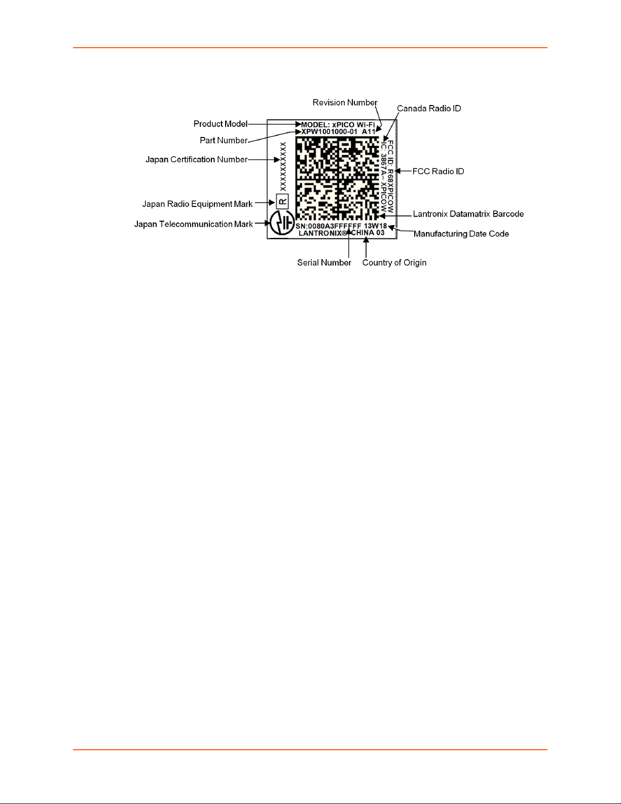
Figure 2-1 xPico Wi-Fi Product Label
2: Introduction
xPico® Wi-Fi® Embedded Device Server User Guide 16
Page 17

3: Configuration Using Web Manager
This chapter describes how to configure the xPico Wi-Fi embedded device server using Web
Manager, the Lantronix browser-based configuration tool. The unit’s configuration is stored in
nonvolatile memory and is retained without power. All changes take effect immediately, unless
otherwise noted. It contains the following sections:
Accessing Web Manager
Web Manager Components
Navigating Web Manager
Accessing Web Manager
To access Web Manager, perform the following steps:
1. Open a standard web browser. Lantronix supports the latest version of Internet Explorer,
Mozilla Firefox, Safari or Chrome browsers.
2. Enter the IP address or hostname of the xPico Wi-Fi in the address bar. The IP address may
have been assigned manually or automatically by DHCP.
3. Enter your username and password.The factory-default username is “admin” and the
password is “PASSWORD” (all capitalized). The Status web page displays product
information, network settings, line settings, and tunneling settings.
xPico® Wi-Fi® Embedded Device Server User Guide 17
Page 18
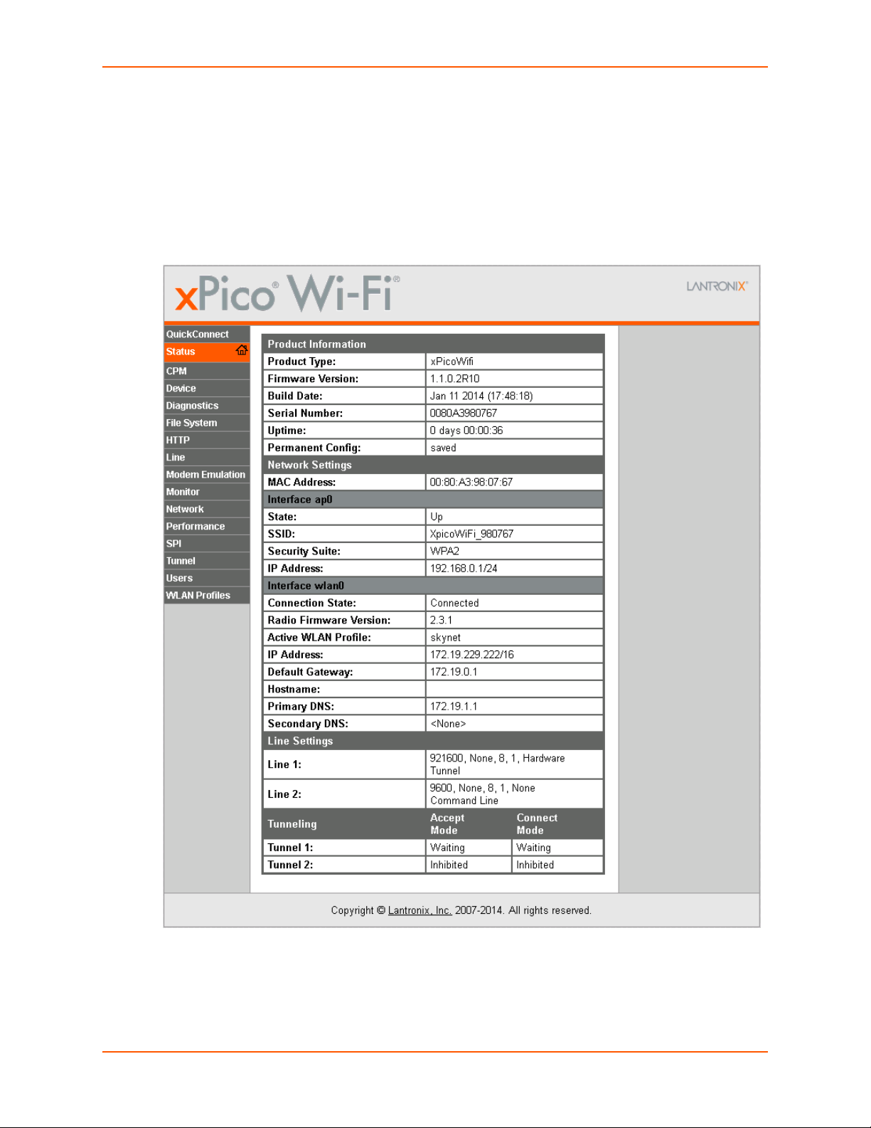
Status Page
The Status page is the first to appear after you log into Web Manager. The Status page also
appears when you click Status tab in Web Manager.
3: Configuration Using Web Manager
Figure 3-1 Status Page
xPico® Wi-Fi® Embedded Device Server User Guide 18
Page 19
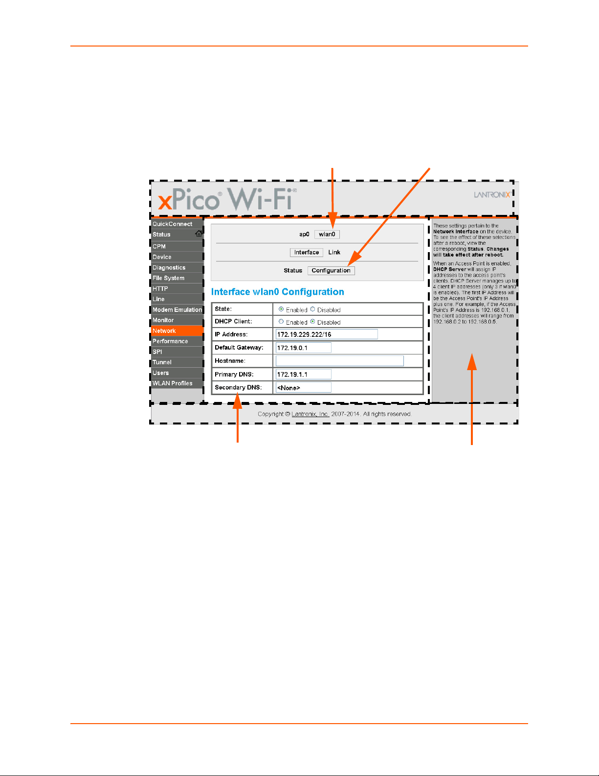
Web Manager Components
Menu Bar
Links to
subpages
Items to
configure
Information
and Help Area
Header
Configuration and/or Status Area
Footer
The layout of a typical Web Manager page is below.
Figure 3-2 Components of the Web Manager Page
3: Configuration Using Web Manager
Navigating Web Manager
The Web Manager provides an intuitive point-and-click interface. A menu bar on the left side of
each page provides links you can click to navigate between pages. Some pages are read-only,
while others let you change configuration settings.
Note: There may be times when you must reboot the xPico Wi-Fi for the new
configuration settings to take effect. The chapters that follow indicate when a change
requires a reboot. Anytime you reboot the unit, this operation will take some time to
complete. Please wait a minimum of 10-20 seconds after rebooting the unit before
attempting to make any subsequent connections.
xPico® Wi-Fi® Embedded Device Server User Guide 19
Page 20

3: Configuration Using Web Manager
Table 3-3 Web Manager Pages
Web Manager Page Description See
Page
Status Shows product information, network, line status, and tunneling settings. 18
CPM Shows information about the Configurable Pins Manager (CPM) and how to
set the configurable pins and roles to work with a device.
Device Lets you reboot the device, restore factory defaults and upload new firmware. 49
Diagnostics Lets you perform various diagnostic procedures. 51
File System Shows file system statistics and lets you perform file system operations. 48
HTTP Shows HyperText Transfer Protocol (HTTP) status and lets you change the
current configuration and authentication settings.
Line Shows statistics and lets you change the current configuration and Command
mode settings of a serial line.
Modem Emulation Lets you view and configure Modem Emulation. 40
Monitor Lets you query and capture information during serial port to serial device
connection.
Network Shows status and lets you configure the network interface. 21
Quick Connect Lets you scan for available network in vicinity and create WLAN profile easily. 28
Performance Lets you change settings effecting performance. 53
SPI Lets you configure SPI settings. 32
Tunnel Lets you change the current configuration settings for an incoming tunnel
connection.
Users Lets you configure Admin User password. 50
43
46
34
55
34
WLAN Profiles Lets you view, edit, delete and create a WLAN profile on a device. 25
xPico® Wi-Fi® Embedded Device Server User Guide 20
Page 21

4: Network Settings
The Network Settings show the status of the Software enabled Access Point (SoftAP) or WLAN
interface/link and let you configure the settings on the device. Interface settings are related to the
configuration of the IP and related protocols. Link settings are related to the physical link
connection, which carries the IP traffic.
The xPico Wi-Fi embedded device server contains two network interfaces. The Software enabled
Access Point interface is also called interface 1 or ap0, and the WLAN interface is called interface
2 or wlan0.
Note: All network settings require a reboot to take effect. Wait a minimum of 20 seconds
after rebooting the unit before attempting to make any subsequent connections.
Network 1 Interface (ap0) Configuration
Table 4-1 shows the network interface settings that can be configured. These settings apply to the
Software enabled Access Point (ap0) interface.
Table 4-1 Network Interface Settings
Network (ap0) Interface
Settings
State Click to enable or disable the SoftAP. If enabled, the DHCP server will assign IP
IP Address Enter the static IP address to use for the interface. You may enter it in one of
Description
addresses to the SoftAP’s clients. A maximum of four clients can be connected
to the SoftAP interface if the STA interface is disabled. If the STA interface is
enabled a maximum of three clients may be connected.
Note: A DHCP lease lasts for a day. If the IP network is managed manually, a
static IP can be used outside the range of the DHCP address pool.
the following ways:
Alone (i.e., 192.168.1.1)
In CIDR format (i.e., 192.168.1.1/24)
With an explicit mask (i.e., 192.168.1.1 255.255.255.0)
To Configure Network 1 Interface Settings
Using Web Manager
To modify Software enabled Access Point (ap0) settings, go to Network on the menu and
select ap0 -> Interface -> Configuration.
Using CLI
To enter the Interface command level: config -> Interface <instance>
Using XML
Include in your file: <configgroup name = "Interface" instance = "ap0">
xPico® Wi-Fi® Embedded Device Server User Guide 21
Page 22

To View Network 1 Interface Status
Using Web Manager
In Network Interface Status, you can view both the current operational settings as well as the
settings that would take effect upon a device reboot.
To view current access point (ap0) settings, go to Network on the menu and select ap0 ->
Interface -> Status.
Using CLI
To enter the Interface command level: status -> Interface <instance>
Using XML
Look for the status header: <statusgroup name = "Interface" instance = "ap0">
Network 1 (ap0) Link Settings
Physical link parameters can be configured for an access point (ap0) Network Interface (see
Table 4-2).
4: Network Settings
Table 4-2 Network 1 (ap0) Link Settings
Network 1 (ap0) Link
Settings
SSID Specify the name of the wireless network (SSID) for the SoftAP.
Channel Specify the channel for the SoftAP.
Suite
Encryption
Passphrase
Description
Specify the security suite to be used for the SoftAP.
None = no authentication or encryption method will be used.
WPA = WiFi Protected Access
WPA2 = Robust Secure Network.
Select one or more encryption types, listed from strongest to least strong.
CCMP = Uses AES as basis and is the strongest encryption option.
TKIP = Uses WEP as the basis, but adds extra checks and variations for
added protection.
Select the passphrase which may consist of up to 63 characters.
Note: This configuration option becomes available only when suites WPA
or WPA2 are selected. Lantronix recommends using a passphrase of 20
characters or more for maximum security. Spaces and punctuation
characters are permitted. The passphrase input is not the same as ASCII
input (as used on some products.) ASCII is translated directly into
hexadecimal bytes according to the ASCII table, while a possibly larger
passphrase is hashed into a key and provides better security through a
larger range of key values.
xPico® Wi-Fi® Embedded Device Server User Guide 22
Page 23

4: Network Settings
Network 1 (ap0) Link
Settings (continued)
Mode Select the desired mode for the link connection from the drop-down menu:
Uptime Enter the length of uptime for the link connection.
Description
Always Up: when enabled, the SoftAP is always on.
Triggered: when enabled, the SoftAP operates in Triggered mode.
Triggered AP mode is a means to enable the xPico Wi-Fi SoftAP via a
hardware signal. This allows a user to have the SoftAP operating only
when an external signal/button is activated. This might be useful when
power consumption is a concern yet the SoftAP is needed. One
potential use is device provisioning. When triggered, the SoftAP will
remain active for the configured uptime waiting for a client to connect. If
no client connects before the uptime expires, the SoftAP goes back
down. If one or more clients connect, the SoftAP will remain active until
the last client disconnects, at which point it will go down. Refer to
Chapter 7: Configurable Pin Manager for details on how to set up the
xPico Wi-Fi unit for this feature
To Configure Network 1 Link Settings
Using Web Manager
To modify network (ap0) Link information, click Network on the menu and select apo > Link >
Configuration.
Using CLI
To enter the Access Point command level: config -> Access Point
Using XML
Include in your file: <configgroup name = "Access Point" instance = "ap0">
To View Network 1 Link Status
Using Web Manager
In Network Link Status, you can view the current operational settings.
To view current network (ap0) settings, go to Network on the menu and select ap0 -> Link ->
Status.
Using CLI
To enter the Access Point command level: status -> Access Point
Using XML
Look for the status header: <statusgroup name = "Access Point" instance =
"ap0">
xPico® Wi-Fi® Embedded Device Server User Guide 23
Page 24

Network 2 (wlan0) Interface Configuration
This page is used to configure the network 2 interface on the device. To see the effect of these
items after a reboot, view the Status page.
Table 4-3 Network Interface Settings
4: Network Settings
Network Interface
Settings
State Click to enable or disable the WLAN interface.
DHCP Client Click to enable or disable the DHCP client. If enabled, any configured IP
IP Address Enter the static IP address to use for the interface. You may enter it in one of
Default Gateway Enter the IP address of the router for this network.
Hostname Enter the hostname for the interface. It must begin with a letter, continue with a
Primary DNS Enter the IP address of the primary Domain Name Server.
Description
address, network mask, gateway or hostname will be ignored. DHCP will autodiscover and eclipse those configured items. When DHCP fails to discover an
IP address, a new address will automaticaly be generated using AutoIP. This
address will be within the 169.254.x.x space. At boot up, after the physical
link is up, the xPico Wi-Fi will attempt to obtain IP settings from a DHCP server
and will periodically renew these settings with the server.
Note: Click renew on Interface Status page to force DHCP lease renewal.
the following ways:
Alone (i.e., 192.168.1.1)
In CIDR format (i.e., 192.168.1.1/24)
With an explicit mask (i.e., 192.168.1.1 255.255.255.0)
Note: This setting will be used if Static IP is active (DHCP Client is Off).
Note: This setting will be used if Static IP is active (DHCP Client is Off).
letter, number or hyphen, and must end with a letter or number. The device will
not register the hostname with a DNS server until the next reboot.
Note: This setting will be used when Static IP is active.
Secondary DNS Enter the IP address of the secondary Domain Name Server.
Note: This setting will be used when Static IP is active.
To Configure Network 2 Interface Settings
Using Web Manager
To modify network 2 WLAN interface information, click Network on the menu and select
wlan0 > Interface > Configuration.
Using CLI
To enter the Interface command level: config -> Interface <instance>
xPico® Wi-Fi® Embedded Device Server User Guide 24
Page 25

4: Network Settings
Using XML
Include in your file: <configgroup name = "Interface" instance = "wlan0">
To View Network 2 Interface Status
Using Web Manager
In Network Interface Status, you can view both the current operational settings as well as the
settings that would take affect upon a device reboot.
To view current access piont (ap0) settings, go to Network on the menu and select wlan0 ->
Interface -> Status.
Using CLI
To enter the WLAN command level: status -> WLAN
Using XML
Look for the status header: <statusgroup name = "Interface" instance =
"wlan0">
Network 2 (wlan0) Link Status
This page shows status of a Link on the device.
To View Network 2 Link Status
Using Web Manager
To view network 2 link interface information, click Network on the menu and select wlan0 >
Link > Status.
Using CLI
To enter the WLAN command level: status -> WLAN
Using XML
Include in your file: <configgroup name = "Interface" instance = "wlan0">
WLAN Profiles
A WLAN profile defines all of the settings necessary to establish a wireless connection with an
access point (in infrastructure mode). A maximum of four profiles can exist on the xPico Wi-Fi
embedded device server at a time and only one profile may be active at any given time.
The xPico Wi-Fi device supports dynamic profiles. Dynamic Profiles are the ones created via
QuickConnect.
xPico® Wi-Fi® Embedded Device Server User Guide 25
Page 26

4: Network Settings
WLAN Profile WEP Settings
WEP is a simple and efficient security mode encrypting the data via the RC4 algorithm. However,
WEP has become more vulnerable due to advances in hacking technology. State of the art
equipment can find WEP keys in five minutes. For stronger security, please use WPA, or better,
WPA2 with AES (CCMP). WEP is only supported on the STA interface.
WLAN Profile WPA and WPA2 Settings
WPA is a security standard specified by the WiFi Alliance and is a close derivative of an early draft
of the IEEE802.11i specification. WEP was becoming vulnerable when finalizing the IEEE802.11i
standard was still far away. WPA2 is WiFi’s subset of the broad IEEE802.11i standard to enforce
better interoperability. The xPico Wi-Fi embedded device server is compliant with both WPA2 and
IEEE802.11i.
To Configure WLAN Profiles
You can view, edit, create or delete a WLAN profile.
Using WebManager
Click WLAN Profiles on the menu.
Using CLI
To enter the WLAN Profile command level: config -> WLAN Profile <instance>
Using XML
Include in your file: <configgroup name = "WLAN Profile" instance = "name">
Table 4-4 Creating, Deleting or Enabling WLAN Profiles
WLAN Profile Basic Settings Description
Create new profile Type the name of the new profile to be created into the Create new
WLAN Profile field. Then, click the Submit button which appears to
create the profile. Once created, the profile name may be clicked so you
may edit profile settings.
Delete (checkbox) Click the Delete checkbox beside the profile(s) to be deleted. Two
buttons will appear:
Click the Apply button to delete the profile for testing purposes. If the
device reboots, this change will not be applied.
Click the Submit button to permanently delete profile(s).
View or Edit
(link to specific profile)
Click on a specific WLAN Profile name to edit the WLAN profile basic
settings.
To Configure WLAN Profile Settings
Using Web Manager
To view or edit an existing WLAN profile, click WLAN Profiles on the menu and select an
existing profile (see Table 4-5, Table 4-6 and Table 4-7).
xPico® Wi-Fi® Embedded Device Server User Guide 26
Page 27

4: Network Settings
Using CLI
To enter the WLAN Profile command level: config -> WLAN Profile <instance>
Using XML
Include in your file: <configgroup name = "WLAN Profile" instance = "name">
Table 4-5 WLAN Profile Basic Settings
WLAN Profile Basic
Description
Settings
Network Name (SSID) Specify the name of the wireless network (SSID.)
State Select to enable or disable this profile.
Table 4-6 WLAN Profile Security Settings
WLAN Profile
Security Settings
Suite Specify the security suite to be used for this profile.
Key Size Select the appropriate key size in bits. Select 40 for WEP40 and WEP64; select
TX Key Index Select one of four index listing keys for transmitting data. Reception is allowed
Key 1-4 Enter one or more encryption keys in hexadecimal format. Enter 10 hexadecimal
WPAx Key Type Select the format of the security key.
WPAx Key Enter the WPAx key.
Description
None = no authentication or encryption method will be used.
WEP = Wired Equivalent Privacy
WPA = WiFi Protected Access
WPA2 = Robust Secure Network.
104 for WEP104 and WEP128.
Note: This option is available if WEP suite is selected above.
with all four keys.
Note: For operability with some products that generate four identical keys from a
passphrase, this index must be one. This option is available if WEP suite is
selected above.
digits (0-9, a-f) for WEP40 and 26 for WEP104. The configured keys are not
shown for security reasons.
Note: This option is available if WEP suite is selected above.
Note: This configuration option becomes available only when suites, WPA or
WPA2 are selected.
Note: This configuration option becomes available only when suites, WPA or
WPA2 are selected and the Hex key type is selected.
xPico® Wi-Fi® Embedded Device Server User Guide 27
Page 28

4: Network Settings
WLAN Profile
Security Settings
WPAX Passphrase Select the password consists of up to 63 characters.
WPAx Encryption Select one or more encryption types, listed from strongest to least strong. At least
Description
Note: Lantronix recommends using a passphrase of 20 characters or more for
maximum security. Spaces and punctuation characters are permitted. The
passphrase input is not the same as ASCII input (as used on some products.)
ASCII is translated directly into hexadecimal bytes according to the ASCII table,
while a possibly larger passphrase is hashed into a key and provides better
security through a larger range of key values. This configuration option becomes
available only when suites, WEP, WPA or WPA2 are selected.
one selection will have to match the Access Points intended to connect with.
CCMP = Uses AES as basis and is the strongest encryption option.
TKIP = Uses WEP as the basis, but adds extra checks and variations for added
protection.
Note: In case the encryption settings on the Access Point(s) can still be chosen,
the capabilities of the Access Point(s) and the other clients that need to use the
network need to be taken into account.This configuration option becomes
available only when suites WPA or WPA2 are selected.
Table 4-7 WLAN Profile Advanced Settings
WLAN Profile Advanced Settings Description
TX Power Maximum Specify the maximum transmission output power in dBm.
Power Management Select to Enable or Disable power management, which reduces the
Power Management Interval Select number of beacons (100 msec interval) between 1 and 5. The
WLAN Quick Connect
WLAN QuickConnect allows users to view and add up to four WLAN profiles from a list of up to 20
wireless devices sorted by RSSI. Details of the selected network are pre-populated, so little or no
configuration is required by the user.
To Configure WLAN Quick Connect
Using Web Manager
To view or edit an existing WLAN Quick Connect settings, click QuickConnect on the menu.
overall power consumption of the xPico Wi-Fi unit, but can increase
latency.
Enabled = allows the xPico Wi-Fi to turn off the receiver when it is
idling.
Disabled = keeps the receiver on at all times.
above-mentioned latency can be up to this number “X” 100 msec.
Using CLI
Not applicable.
xPico® Wi-Fi® Embedded Device Server User Guide 28
Page 29

Using XML
Not applicable.
4: Network Settings
Table 4-8 WLAN Quick Connect
WLAN Quick Connect
Settings
Network Name (search field) Enter a network name and click Scan to search for a network.
Scan “<network SSID>” Perform a scan for devices within range of the xPico Wi-Fi. Including the
Network Name (link) Lists the SSID of a network. Click a specific Network Name to display the
BSSID Lists the basic service set identifier. This is a unique 48-bits address that
CH Provides the channel number of a network.
RSSI Displays an instantaneous value indicating the signal strength of the
Security Suite Lists the security suite of a network (e.g., WEP, WPA, WPA2).
Description
optional network SSID limits the scan to devices configured with the
specified network SSID. Omitting the network SSID performs a scan for all
devices in range.
Quick Connect profile. If you provide the Password for a specific Quick
Connect Profile, you can add that profile to your list of WLAN Profiles. Up
to four WLAN profiles may be added, and only one may be connected at
any given time.
identifies the access point that creates the wireless network.
network. The best to worst signal strength is indicated by green, yellow and
red respectively.
Note: RSSI reported in scan results is a single sampling.
xPico® Wi-Fi® Embedded Device Server User Guide 29
Page 30

5: Interface Settings
Line Settings
The Line Settings allow configuration of the serial lines (ports). Some settings may be specific to
only certain lines. Such settings are noted below.
Note: The settings described below apply to both Line 1 and Line 2 unless otherwise
noted.
Table 5-1 Line Configuration Settings
Line Settings Description
Name Enter a name or short description for the line, if desired. By default, there is
no name specified. A name that contains white space must be quoted.
State Select to Enable or Disable the operational state of the Line. The default is
an enabled state.
Protocol Set the operational protocol for the Line. The default is Tunnel for Line 1 and
Command Line for Line 2. Choices are:
Command Line
Modem Emulation
Monitor
None
Trouble Log
Tunnel = Serial-Network tunneling protocol (Line 1 only)
Baud Rate Set the Baud Rate (speed) of the Line. The default is 9600.
A custom speed or any set speed between 1200 and 921600 may be
selected: 1200, 2400, 4800, 9600, 19200, 38400, 57600, 115200, 230400,
460800, 921600. If a custom speed is selected, indicate the bits per second in
the field which appears.
Parity Set the Parity of the Line. The default is None.
Note: Serial lines do not support the following Data Bit/Parity combinations:
a) 7 Data Bits with No Parity and 1 Stop Bit.
b) 8 Data Bits with 2 Stop Bits.
Data Bits Set the number of data bits for the Line. The default is 8.
Note: Serial lines do not support the following Data Bit/Parity combinations:
a) 7 Data Bits with No Parity and 1 Stop Bit.
b) 8 Data Bits with 2 Stop Bits.
Stop Bits Set the number of stop bits for the Line. The default is 1.
Flow Control Set the flow control for the Line. The default is None. Hardware flow control is
only supported on Line 1.
Xon Char Specify the Xon Character which is used when Flow Control is set to
Software. Set the prefix in one of the three ways:
Prefix decimal with prefix hexadecimal and 0x
Prefix hexadecimal with 0x
Prefix as a single control character with <control>
xPico® Wi-Fi® Embedded Device Server User Guide 30
Page 31

5: Interface Settings
Line Settings Description
Xoff Char Specify the Xoff Character which is used when Flow Control is set to
Software. Set the prefix in one of the three ways:
Prefix decimal with prefix hexadecimal and 0x
Prefix hexadecimal with 0x
Prefix as a single control character with <control>
Gap Timer Set the Gap Timer delay to Set the number of milliseconds to pass from the
last character received before the driver forwards the received serial bytes.
By default, the delay is four character periods at the current baud rate
(minimum 1 msec). Gap Timer range is 1 to 5000 milliseconds.
Threshold Set the number of threshold bytes which need to be received in order for the
driver to forward received characters. Default value is 56 bytes.
To Configure Line Settings
Note: The following section describes the steps to view and configure Line 1 settings;
these steps apply to other line instances of the device.
Using Web Manager
To configure a specific line, click Line in the menu and select Line 1 -> Configuration
(Table 5-1).
Using CLI
To enter the Line command level: config -> Line <instance>
Using XML
Include in your file: <configgroup name = "Line" instance = "1">
To View Line Status
Using Web Manager
To view statistics for a specific line, click Line in the menu and select Line 1 -> Status.
Using CLI
To enter the Line command level: status -> Line <instance>
Using XML
Look for the status header: <statusgroup name = "Line" instance = "1">
xPico® Wi-Fi® Embedded Device Server User Guide 31
Page 32

Serial Perpheral Interface (SPI) Settings
SPI settings pertaining to the bus master device can be modified in the xPico Wi-Fi unit. SPI
settings, like line settings, allow for the selection of a protocol to be used with SPI. Changes take
effect immediately.
Table 5-2 SPI Configuration Settings
Line Settings Description
Name Enter a name or short description for the line, if desired. By default, there is
no name specified. This name is for display only.
State Select to Enable or Disable the SPI.
Protocol Select the operational protocol for connection to the SPI:
None: selects no application to connect to the SPI.
Monitor: selects Monitor application to connect to the SPI.
Target Speed Set the target clock speed of the SPI in Hz (range is 234.375 KHz - 30 MHz).
The target speed may be lowered to the closest operating speed capability of
the device. If so, a warning will be noted. 0 or clearing the selection selects
the minimum speed.
Idle Clock Level Select the level of the clock or clock polarity (CPOL) when the clock is idle:
Low: the idle clock is at a low level. This is equivalent to CPOL=0.
High: the idle clock is at a high level. This is equivalent to CPOL=1.
Clock Edge Select the clock edge or clock phase (CPHA) for latching data:
First: each bit is latched on the first edge of the clock. This is equivalent to
CPHA=0.
Second: each bit is latched on the second edge of the clock. This is
equivalent to CPHA=1.
Bits Per Word Select the number of bits per word to transfer. Choices in drop-down menu
are 8 or 16.
First Transfer Select the first transfer bit of each word. Choicse in drop-down menu include:
Most Significant Bit
Least Signficant Bit
5: Interface Settings
To Configure SPI Settings
Using Web Manager
To configure the SPI bus master device settings, click SPI in the menu and select
Configuration.
Using CLI
To enter the SPI command level: config -> SPI
Using XML
Include in your file: <statusgroup name = "SPI" instance = "1">
xPico® Wi-Fi® Embedded Device Server User Guide 32
Page 33

5: Interface Settings
To View SPI Status
Using Web Manager
To view the current status and statistics for the SPI bus master device, click SPI in the menu
and select Status.
Using CLI
To enter the SPI command level: status -> SPI
Using XML
Include in your file: <statusgroup name = "SPI" instance = "1">
xPico® Wi-Fi® Embedded Device Server User Guide 33
Page 34

6: Tunnel Settings
The xPico Wi-Fi embedded device server has two lines available for tunneling.
Tunnel Settings
Tunneling allows serial devices to communicate over a network, without “being aware” of the
devices which establish the network connection between them. Tunneling parameters are
configured using the Tunnel menu and submenus. The Tunnel settings allow you to configure
how the Serial-Network tunneling operates.
Note: The following section describes the steps to view and configure Line 1 settings;
these steps apply to other line instances of the device.
Line Settings
These serial settings for the tunnel apply to the Serial Line interface. The Line Settings and
Protocol are displayed for informational purposes and must be configured from the Line settings.
Table 6-1 Tunnel Line Settings
Tunnel Serial
Settings
Line Settings Line Settings information here is display only. Go to the section, To Configure
Protocol Protocol information here is display only. Go to the section, To Configure Line
DTR Select the DTR conditions in which Data Terminal Ready control signal on the
Description
Line Settings to modify these settings.
Settings to modify these settings.
Serial Line is asserted.
Asserted while connected (Causes DTR to be asserted whenever either a
connect or an accept mode tunnel connection is active).
Continuously asserted
Unasserted
To View Tunnel Serial Settings
Using Web Manager
To view the Serial Settings for a specific tunnel, click Tunnel in the menu and select Tunnel 1
-> Line.
Using CLI
To enter the Tunnel command level: config -> Tunnel <instance>
Using XML
Include in your file: <configgroup name = "Tunnel Line" instance = "1">
xPico® Wi-Fi® Embedded Device Server User Guide 34
Page 35

6: Tunnel Settings
Packing Mode
With Packing, data from the serial Line is not sent over the network immediately. Instead, data is
queued and sent in segments, when either the timeout or byte threshold is reached. Packing
applies to both Accept and Connect Modes.
Table 6-2 Tunnel Packing Mode Settings
Tunnel Packing Mode
Description
Settings
Mode Configure the Tunnel Packing Mode. Choices are:
Disable = Data not packed.
Timeout = data sent after timeout occurs.
Send Character = data sent when the Send Character is read on the Serial
Line.
Timeout Set the timeout value, in milliseconds, after the first character is received on
the serial line, before data is sent on the network. Valid range is 1 to 30000
milliseconds. Default is 1000.
Note: This configuration option becomes available when Timeout is the
selected Mode.
Threshold Set the threshold (byte count). If the received serial data reaches this
threshold, then the data will be sent on the network. Valid range is 100 to
1450 bytes. Default is 512.
Note: This configuration option becomes available when Timeout is the
selected Mode.
Send Character Enter Control Characters in any of the following forms:
<control>J
0xA (hexadecimal)
\10 (decimal)
If used, the Send Character is a single printable character or a control
character that, when read on the Serial Line, forces the queued data to be
sent on the network immediately.
Note: This configuration option becomes available when Send Character is
the selected Mode.
Trailing Character Enter Control Characters in any of the following forms:
<control>J
0xA (hexadecimal)
\10 (decimal).
If used, the Trailing Character is a single printable character or a control
character that is injected into the outgoing data stream right after the Send
Character. Disable the Trailing Character by blanking the field (setting it to
<None>).
Note: This configuration option becomes available when Send Character is
the selected Mode.
xPico® Wi-Fi® Embedded Device Server User Guide 35
Page 36

6: Tunnel Settings
To Configure Tunnel Packing Mode Settings
Using Web Manager
To configure the Packing mode for a specific tunnel, click Tunnel in the menu and select
Tunnel 1 -> Packing.
Using CLI
To enter the Tunnel command level: config -> Tunnel <instance>
Using XML
Include in your file: <configgroup name = "Tunnel Packing" instance = "1">
Accept Mode
In Accept mode, the xPico Wi-Fi listens (waits) for incoming connections from the network. A
remote node on the network initiates the connection.
The configurable local port is the port the remote device connects to for this connection. There is
no remote port or address. The default local port is 10001.
Serial data can still be received while waiting for a network connection, keeping in mind serial data
buffer limitations.
Table 6-3 Tunnel Accept Mode Settings
Tunnel Accept Mode
Settings
Mode Set the method used to start a tunnel in Accept mode. Choices are:
Local Port Set the port number for use as the network local port. The default local port
Protocol Select the TCP type for use with Accept Mode.
Start Character Enter the start character which will enable the tunnel to listen for a network
Description
Disable = do not accept an incoming connection.
Always = accept an incoming connection (default).
Any Character = start waiting for an incoming connection when any
character is read on the serial line.
Start Character = start waiting for an incoming connection when the
start character for the selected tunnel is read on the serial line.
is 10001.
connection. The start character may be designated as a single printable
character or as a control character. Control characters may be input in any
of the following forms:
<control>J or 0xA (hexadecimal) or \10 (decimal)
Note: This configuration option becomes available when Start Character
is the selected Mode.
xPico® Wi-Fi® Embedded Device Server User Guide 36
Page 37

6: Tunnel Settings
Tunnel Accept Mode
Description
Settings (continued)
Flush Start Character Enable or disable the flush start character:
Enabled = prevents forwarding of a start character from the Line into
the network.
Disabled = the flush start character allows forwarding of a start
character from the line into the network.
Note: This configuration option becomes available when Start Character
is the selected Mode.
Flush Line Set whether the serial line data buffer is flushed upon a new network
connection. Choices are:
Enabled = serial data buffer is flushed on network connection
Disabled = serial data buffer is not flushed on network connection
(default)
Block Line Set whether Block Line is enabled for debugging purposes. Choices are:
Enabled = if Enabled, incoming characters from the serial line will not
be forwarded to the network. Instead, they will be buffered and will
eventually flow off the serial line if hardware or software flow control is
configured.
Disabled = this is the default setting; incoming characters from the
Serial Line are sent into the network. Any buffered characters are sent
first.
Block Network Set whether Block Network is enabled for debugging purposes. Choices
are:
Enabled = if Enabled, incoming characters from the network will not be
forwarded to the Serial Line. Instead, they will be buffered and will
eventually flow off the network side.
Disabled = this is the default setting; incoming characters from the
network are sent on the Serial Line. Any buffered characters are sent
first.
Password Enter a password. This password can be up to 31 characters in length and
must contain only alphanumeric characters and punctuation. When set,
clients must send the correct password string to the unit within 30 seconds
from opening network connection in order to enable data transmission.
The password sent to the unit must be terminated with one of the following:
0A (Line Feed)
00 (Null)
0D 0A (Carriage Return/Line Feed)
0D 00 (Carriage Return/Null)
If, Prompt for Password is set to Enabled and a password is provided,
the user will be prompted for the password upon connection.
To Configure Tunnel Accept Mode Settings
Using Web Manager
To configure the Accept Mode for a specific tunnel, click Tunnel in the menu and select
Tunnel 1 -> Accept.
Using CLI
To enter the Tunnel command level: config -> Tunnel <instance>
xPico® Wi-Fi® Embedded Device Server User Guide 37
Page 38

6: Tunnel Settings
Using XML
Include in your file: <configgroup name = "Tunnel Accept" instance = "1">
Connect Mode
Specifies the conditions for connecting any Accept Mode connection that may be established
locally.
Table 6-4 Tunnel Connect Mode Settings
Tunnel Connect
Description
Mode Settings
Mode Select the method to start the Connect Tunnel:
Disabled: never started.
Always: always started
Any Character: started when any character is detected on the Serial Line
Start Character: started when the Start Character is detected on the Serial Line.
Local Port View and if desired, override the default Local Value values.
Local port default values: Tunnel 1 is 10001 and Tunnel 2 is 10002.
Blank the display field to restore to default random setting.
Host <Number>
(Edit button)
Lists exhisting hosts, if any for viewing and editing.
Click the Edit button beside a particular host to view the Address, Port and
Protocol fields for this host.
Make any changes, as desired in the Address, Port and Protocol fields and click
Submit to save.
Up to 2 hosts can be established. Additional hosts become available for editing/
submitting as a host is edited.
Connections Select the type of connection.
Sequential: connections for tunneling will begin from host 1 and proceed in
sequence until a connection is accepted.
Simultaneous: all hosts accepting connetions will be connected.
Reconnect Time Enter the reconnection time, which specifies how long the xPico Wi-Fi device server
will wait in seconds before trying to reconnect to the remote host after a failed
attempt or closed connetion. Blank the display field to restore the default.
Flush Line Select to enable or disable the flush line at the time a connection is established with
the network.
Enabled: buffered characters from the serial line will be discarded when a
connection is established.
Disabled: any characters received on the serial line will be buffered and sent
after a connection is established.
Block Line Select to enable or disable the block line, which is used for debugging purposes.
Enabled: incoming characters from the serial line will not be forwarded to the
network but will be buffered and will eventually flow off the serial line, if hardware
or software flow control is configured.
Disabled: incoming characters from the serial line are sent to the network. Any
buffered characters are sent first. This is the “normal” setting.
xPico® Wi-Fi® Embedded Device Server User Guide 38
Page 39

6: Tunnel Settings
Tunnel Connect
Mode Settings
Block Network Select to enable or disable the block network, which is used for debugging
Description
purposes.
Enabled: incoming characters from the network will not be forwarded to the
serial line but will be buffered and eventually flow off the network side.
Disabled: incoming characters from the network are sent on into the serial line.
Any buffered characters are sent first. This is the “normal” setting.
To Configure Tunnel Connect Mode Settings
Using Web Manager
To configure the Disconnect Mode for a specific tunnel, click Tunnel in the menu and select
Tunnel 1 -> Connect.
Using CLI
To enter the Tunnel command level: config -> Tunnel <instance>
Using XML
Include in your file: <configgroup name = "Tunnel Connect" instance = "1">
Disconnect Mode
Specifies the optional conditions for disconnecting any Accept Mode connection that may be
established. If any of these conditions are selected but do not occur and the network disconnects
from the device, a Connect Mode connection will attempt to reconnect. However, if none of these
conditions are selected, a closure from the network is taken as a disconnect.
Table 6-5 Tunnel Disconnect Mode Settings
Tunnel Disconnect
Mode Settings
Stop Character Enter the Stop Character which when received on the Serial Line, disconnects the
Modem Control Select to enable or disable the disconnect when modem control pin is not asserted
Timeout Enter the number of milliseconds a tunnel may be idle before disconnection. The
Flush Line Set whether to flush the Serial Line when the Tunnel is disconnected. Choices are:
Description
tunnel. The Stop Character may be designated as a single printable character or
as a control character. Control characters may be input in any of the following
forms: <control>J or 0xA (hexadercimal) or \10 (decimal). Disable the Stop
Character by blanking the field to set it to <None>.
on the serial line.
value of zero disables the idle timeout.
Enabled
Disabled (default)
xPico® Wi-Fi® Embedded Device Server User Guide 39
Page 40

6: Tunnel Settings
To Configure Tunnel Disconnect Mode Settings
Using Web Manager
To configure the Disconnect Mode for a specific tunnel, click Tunnel in the menu and select
Tunnel 1 -> Disconnect.
Using CLI
To enter the Tunnel command level: config -> Tunnel <instance>
Using XML
Include in your file: <configgroup name = "Tunnel Disconnect" instance = "1">
Statistics
Tunnel statistics contains data counters, error counters, connection time and connection
information. Statistics are available at each individual connection and aggregated across all
connections.
To View Tunnel Statistics
Using Web Manager
To view statistics for a specific tunnel, click Tunnel in the menu and select the Tunnel 1 ->
Status.
Using CLI
To enter the Tunnel command level: status -> Tunnel <instance>
Using XML
Look for the status header: <statusgroup name = "line" instance = "1">
Modem Emulation Settings
Note: The following section describes the steps to view and configure Modem Emulation
1 settings; these steps also apply to Modem Emulation 2 settings.
Table 6-6 Modem Emulation Settings
Modem Emulation
Settings
Listen Port Specify a listen port to accept connections.
Echo Pluses Select to enable or disable echo pluses to be echoed back during “pause +++
Echo Commands Select to enable or disable echo commands. If enabled, characters read on the
Description
pause” escape sequence on the serial line.
serial line are echoed while the modem is in Modem Command Mode.
xPico® Wi-Fi® Embedded Device Server User Guide 40
Page 41

6: Tunnel Settings
Modem Emulation
Description
Settings
Verbose Response Select to enable or disable verbose response. If enabled, modem response codes
are sent out on the serial line.
Response Type Select either Text or Numeric representation for the modem response codes sent
out on the serial line.
Error Unknown
Commands
Incoming
Select to enable or disable error unknown commands. If enabled, ERROR is
returned to the serial line for unrecognized AT commands.
Select Automatic, Manual or Disabled for the handling of incoming connections.
Connection
Connect String Specify a customized string to be sent with the CONNECT modem response code
to the serial line, if any.
Display Remote IP Select to enable or disable display remote IP. If enabled, the incoming ring sent on
the serial line is followed by the IP address of the caller.
Using Web Manager
To configure the modem emulation for a specific tunnel, click Modem Emulation in the menu
and select Modem Emulation 1 -> Configuration.
To view the modem emulation status for a specific tunnel, click Modem Emulation in the
menu and select Modem Emulation 1 -> Status.
Using the CLI
To enter the Modem Emulation command level: config -> Modem Emulation <1>
Using XML
Include in your file: <configgroup name=”Modem Emulation” instance=”1”>
Table 6-7 Modem Emulation Commands and Descriptions
Command Description
AT? Help. Displays this table.
ATA Answer incoming call request (if ATS0=2 or greater).
ATD Connects to the configured Connect Mode address and port.
ATD <address>:<port> Connects to the specified address and port.
ATD 0 Enters the Command Line Interface (CLI); exit returns to AT commands.
ATDP Same as ATD.
ATDT Same as ATD.
ATEn Switches echo in command mode (n=0: off, n=1: on).
ATH Disconnects the network session.
ATI Displays modem information.
ATO Switches to data mode if connection still exists. Reverse of '+++'.
ATQn Quiet mode (n=0: enable results code, n=1: disable results code.)
ATS0=n Accept connection. (n=0: no, n=1: auto, n=2+: via ATA command).
xPico® Wi-Fi® Embedded Device Server User Guide 41
Page 42

6: Tunnel Settings
Command Description
ATUn Accept unknown commands. (n=0: off, n=1: on).
ATVn Verbose mode (n=0: numeric result codes, n=1: text result codes.)
ATXn Command does nothing and returns OK status.
ATZ Restore active settings from defaults.
AT&F Reset saved settings in NVR to factory defaults.
AT&V Display current and saved settings.
AT&W Save active settings to NVR.
AT&Z Restore active settings from NVR.
A/ Repeat last command.
+++ Switches to command mode if entered from serial port during connection.
xPico® Wi-Fi® Embedded Device Server User Guide 42
Page 43

7: Configurable Pin Manager
The Configurable Pin Manager (CPM) is responsible for the assignment and control of the
configurable pins (CPs) available on the xPico Wi-Fi embedded device server. There are eight
configurable pins on the xPico Wi-Fi unit.
You must configure the CPs by making them part of a role. A CP role may consist of one or more
CPs. This increases flexibility when incorporating the xPico Wi-Fi device into another system.
Note: The blue text in the XML command strings of this chapter are to be replaced with
a user-specified name.
Configurable Pin Status
Each CP is associated with an external hardware pin. The Current Configuration table shows the
sample settings for each CP.
Table 7-1 Current Configurable Pins
CP Ref Usage Assert Mode Value Roles Active in Role
CP1 Pin 35 Input High Push-Pull 0 1 <available>
CP2 Pin 26 Input High Push-Pull 1 1 <available>
CP3 Pin 28 Input High Push-Pull 0 0 <available>
CP4 Pin 30 Input High Push-Pull 1 0 <available>
CP5 Pin 32 Input High Push-Pull 0 0 <available>
CP6 Pin 34 Input High Push-Pull 0 0 <available>
CP7 Pin 27 Input High Push-Pull 0 0 <available>
CP8 Pin 3 Input High Push-Pull 0 -0 <available>
Table 7-2 CP Status
CPM – CPs Status Description
Ref Indicates the pin number on the device which corresponds to this
configurable pin.
Usage Indicates whether this pin is set as Input, Output or Reserved (for a
different use).
Assert Indicates the polarity of the configurable pin as High or Low.
Mode Indicates whether this pin is setup for push-pull or if it enables an
internal weak pullup.
Value Indicates the logical value of the configurable pin.
Roles Indicates the number of configurable pin roles which refer to this pin.
xPico® Wi-Fi® Embedded Device Server User Guide 43
Page 44

7: Configurable Pin Manager
CPM – CPs Status (continued) Description
Active in Role Indicates the current active role that uses this pin. If there is currently
no role, <available> will display. Click a specific action as desired for
the configurable pin:
Usage Input
Usage Output
Usage Unused
Assert High
Assert Low
Mode Push-Pull
Mode Weak Pullup
Value 0
Value 1
Note: To modify a CP, all roles in which it is a member must be disabled.
Note: The changes to a CP configuration are not saved in FLASH. Instead, these CP
settings are used when the CP is added to a CP Role. When the CP Role is saved, its CP
settings are saved with it. Thus, a particular CP may be defined as "Input" in one role but
as "Output" in another. Only one role containing any particular CP may be enabled at
once.
Roles
The CP Role settings allow for the management of CP roles. Roles are configurable, may be
enabled or disabled and can be assigned or unassigned to a configurable pin. A role, based on its
state, can trigger outside events. Only an enabled role can be a trigger.
xPico Wi-Fi roles available for assignment to a configurable pin include the following:
Role AP Trigger
Role Line 1 DSR
Role Line 1 DTR
Role Line 2 DSR
Role Line 2 DTR
Role Line 2 Flow.CTS
Role Line 2 Flow.RTS
Role SPI.CS
Role SPI.INT
Role SPI.MISO
Role SPI.MOSI
Role SPI.SCK
The items listed in the Table 7-3 can be configured for each role.
xPico® Wi-Fi® Embedded Device Server User Guide 44
Page 45

Table 7-3 Role Configuration
7: Configurable Pin Manager
CPM – Role Current
Description
Configuration
CP View or modify the number of the configurable pin assigned to this role. Enter 0
or blank the field to revert to <No CP Selected>.
State View or modify whether the role is enabled or disabled for use.
Assert View or modify the polarity of the cp role as High or Low.
Mode Shows the number of CPs assigned to the role.
To Configure CPM Settings
Using Web Manager
To view or configure a configurable pin, click CPM in the menu, select CPs then the Detail link
to the right of a specific CP to configure.
To configure a CPM role, click CPM in the menu, select Roles > Configuration and then the
Edit link to the right of a specific role to configure.
To view a CPM role status, click CPM in the menu, select Roles > Status and then the Detail
link to the right of a specific role to view details.
Using the CLI
To enter the CPM command level: config -> CPM
Using XML
Include in your file: <configgroup name=”cpm”>
Include in your file: <statusgroup name= “CPM Roles”>
Include in your file: <statusgroup name= “CPM CPs”>
xPico® Wi-Fi® Embedded Device Server User Guide 45
Page 46

8: Services Settings
HTTP Settings
Hypertext Transfer Protocol (HTTP) is the transport protocol for communicating hypertext
documents on the Internet. HTTP defines how messages are formatted and transmitted. It also
defines the actions web servers and browsers should take in response to different commands.
HTTP Authentication enables the requirement of usernames and passwords for device access.
Table 8-1 HTTP Settings
HTTP Settings Description
State Select to enable or disable the HTTP server:
Enabled (default)
Disabled
Port Enter the port for the HTTP server to use. The default (80) will be restored
when the field is cleared.
Inactivity Timeout Enter the amount of time the HTTP server will hold power on after completing
a request. This setting only applies if HTTP Server is enabled in
Performance.
URI Displays the root of the Uniform Resource Identifier (URI) to apply access
control settings.
Note: The URI must begin with ‘/’ to refer to the entire file system.
Auth Type Select the authentication type:
None: no authentication is necessary.
Basic: encodes passwords using Base64.
Users Displays the username allowed to access the configured URI.
To Configure HTTP Settings and Access Control
Using Web Manager
To configure HTTP settings, click HTTP in the menu and select Configuration.
Using CLI
To enter the HTTP Server command level: config -> HTTP Server
Using XML
Include in your file: <configgroup name = "HTTP Server">
Include in your file: <configgroup name = "HTTP Server Access Control"
instance=”1”>
xPico® Wi-Fi® Embedded Device Server User Guide 46
Page 47

To View HTTP Status
Using Web Manager
To view HTTP status, click HTTP in the menu and select Status.
Using CLI
To enter the HTTP Server command level: status -> HTTP Server>
Using XML
Look for the status header: <statusgroup name = "HTTP Server">
8: Services Settings
xPico® Wi-Fi® Embedded Device Server User Guide 47
Page 48

9: Maintenance and Diagnostics Settings
File System Settings
The xPico Wi-Fi embedded device server uses a flash file system to store files. The file system
can be formatted and compacted: formatting erases all files while preserving configuration, and
compacting reclaims dirty space while preserving all files.
The file system also provides statistics and the ability to create, delete, and manipulate files and
directories.
File System Statistics
Table 9-1 File System Statistics Settings
File System Commands Description
Compact Compact the File System to reclaim dirty flash storage while preserving any
existing files and directories.
Format Format the File System to erase all existing files and directories, while
preserving configuration.
To View File System Statistics, Compact or Format the File System
Using Web Manager
To view file system statistiscs, compact or format the file system, click FIle System in the
menu.
Using CLI
To enter the File System command level: status -> File System
Using XML
Look for the status header: <statusgroup name = "File System”>
File Display
It is possible to view the list of existing files, and to view their contents.
To Display Files
Using Web Manager
To view existing files and file contents, click File System in the menu and select Browse.
Using the CLI
To enter the File System command level: enable -> file system
xPico® Wi-Fi® Embedded Device Server User Guide 48
Page 49

9: Maintenance and Diagnostics Settings
Using XML
Not applicable.
File Manipulation
The xPico Wi-Fi embedded device server allows for files to be deleted, moved, renamed, and
uploaded via HTTP. Directories can be created, deleted, moved, and renamed.
To Transfer or Modify File System Files
Using Web Manager
To create a new file or directory, upload an existing file, copy or move a file, click File System
in the menu and select Browse.
Using the CLI
To enter the File System command level: enable -> file system
Using XML
Not applicable.
Device Settings
The xPico Wi-Fi Device settings allow for rebooting the device, restoring factory defaults, and
uploading new firmware.
Anytime you reboot the unit, this operation will take some time to complete. Please wait a
minimum of 10-20 seconds after rebooting the unit before attempting to make any subsequent
connections.
Device Management
System Settings Description
Save Any cached configuration changes are committed, so they will apply after a
Reboot (button)
Factory Defaults (button)
Firmware Upload (button)
Table 9-2 Device Management Settings
reboot. Without saving, cached configuration changes are lost after a reboot.
Reboots the device. When rebooted, your browser should be refreshed and
redirected to the main status page after 30 seconds.
Note: The redirect will not work as expected if the IP address of the devices
change after reboot. After setting the configuration back to factory defaults,
the device will automatically be rebooted. If Web Manager is access through
SoftAP, your connection to SoftAP may be dropped when device reboots.
Restores the device to the original factory settings. All configuration will be
lost. The xPico Wi-Fi automatically reboots upon setting back to the defaults.
Device will reboot to the Over-The-Air (OTA) firmware upgrade application to
continue the operation.
xPico® Wi-Fi® Embedded Device Server User Guide 49
Page 50

Note: Go to Chapter 13: Updating Firmware for directions on uploading new firmware.
To Save Configuration, Reboot, Restore Factory Defaults or Upload Firmware
Using Web Manager
To access the area with options to reboot, restore to factory defaults, upload new firmware,
click Device in the menu.
Using CLI
To enter the Device command level: status -> Device
Using XML
Look for the status header: <statusgroup name = "Device”>
Admin User
9: Maintenance and Diagnostics Settings
Table 9-3 Admin User Settings
System Settings Description
Password Enter a new password. Users will need to log in again after changing the
password.
To Configure Admin User on the Device
Using Web Manager
To change the password setting, click Users in the menu.
Using CLI
To enter the Users command level: config -> Users
Using XML
Look for the status header: <configgroup name = "Users" instance=”admin”>
xPico® Wi-Fi® Embedded Device Server User Guide 50
Page 51

Diagnostics Settings
The xPico Wi-Fi embedded device server has tools for diagnostics and statistics. Options allow for
the viewing of hardware, IP sockets, threads, and buffer pools.
To View Hardware Status
Using WebManager
To view hardware information, click Diagnostics in the menu and select Hardware.
Using CLI
To enter the Diagnostics command level: status -> Diagnostics
Using XML
Include in your file: <statusgroup name=”Diagnostic Hardware”>
To View IP Socket Status
9: Maintenance and Diagnostics Settings
Using WebManager
To view IP Sockets information, click Diagnostics in the menu and select IP Sockets.
Using CLI
To enter the IP Sockets command level: status -> Diagnostics -> IP Sockets
Using XML
Include in your file: <statusgroup name=”Diagnostics IP Sockets”>
To View Buffer Pool Status
Using WebManager
To view information for each Buffer Pool, click Diagnostics in the menu and select Buffer
Pools.
Using CLI
To enter the Buffer Pools command level: status -> Diagnostics -> Buffer Pools
Using XML
Include in your file: <statusgroup name=”Diagnostic Buffer Pools”
xPico® Wi-Fi® Embedded Device Server User Guide 51
Page 52

10: Advanced Settings
XML Import and XML Export
The xPico Wi-Fi embedded device server allows for the configuration of devices by using XML
configuration records (XCRs). You can export an existing configuration for use on other xPico WiFi devices or import a saved configuration file. XML import and export are only available through
the CLI.
Note: The xPico Wi-Fi module itself only supports serial TTL signaling on both Lines. If
used with the evaluation board (see the xPico Embedded Device Server Evaluation Kit
User Guide), then Line 2 may be routed through a serial-to-USB converter via jumper
settings.
To ensure optimal performance when configuring and managing the device using XML, it is
required that serial port flow control is enabled. This maybe hardware or soft flow control.
Lantronix recommends the use of hardware flow control to ensure the best throughput.
To Import or Export XML Configuration
1. Connect the xPico Wi-Fi embedded device server to a PC using:
- A null modem cable for line 1.
- A USB cable for line 2. The USB driver will automatically install into your PC.
2. Configure command line on line and select hardware or software flow control.
Note: If you are using line 2, select software flow control as hardware flow control is
not supported.
3. Open a terminal emulator from the PC, e.g., Tera Term version 4.58.
4. Select the Com port or USB serial port and set the serial settings, on the terminal emulator, to
match the appropriate line on the device server.
5. When you see prompt ‘>’ on the terminal emulator, type 'h' to view the single character
commands available.
c>h
COMMAND LINE INTERFACE HELP
<tab> fill in possible command
<enter> run command as edited
*<enter> show help on matching commands
? list matching commands
<left arrow> move cursor left
<right arrow> move cursor right
<up arrow> previous command
<down arrow> later command
<backspace> delete to left
<delete> delete to left
<Paste XML> import configuration
<control> <escape>
xPico® Wi-Fi® Embedded Device Server User Guide 52
Page 53

10: Advanced Settings
--------------------------------- ----------------------------------
a move cursor to begin of line b move cursor backward word
d delete character under cursor f move cursor forward word
e move cursor to end of line [A previous command
k delete to end of line [B later command
l redraw line [C move cursor right
r redraw line [D move cursor left
u delete to begin of line <escape> delete word to left
w delete word to left
>
6. Enter XML commands and utilize either xcr dump or secret xcr dump to dump xml
configuration information.
7. Copy and paste the configuration text into notepad or some other basic text editor.
8. Remove all the spaces in the script within the text editor. This basic text is the exported XML
configuration and is now available for copy-paste into any xPico Wi-Fi embedded device server.
9. Make any additional changes to the configuration text to modify the XML configuration.
10. Copy and paste <CR> all of the text into the terminal emulator connected to the desired xPico
Wi-Fi embedded device server, to "import" the new configuration.
Note: Software flow control experiences overrun above 460800 baud.
Performance Settings
Change settings pertaining to performance including application, maximum time powered down,
wake-up pin power up, and time powered up.
Modem Emulation Settings Description
Application Select the performance application:
Maximum Time Powered Down Indicates the maximum amount of time for the device to be
WKUP Pin Power Up Enable or disable WKUP pin power up. The device wakes up on
Time Powered Up Indicates the amount of time for the device to be powered up. After
Table 10-1 Performance Settings
Tunnel Accept
Tunnel Connect
Command Line
HTTP Server
Any application selected for performance may hold the power on
longer or wake up sooner.
powered down. After this time, the device wakes up.
the rising edge of WKUP, if enabled.
this time, the device powers down.
xPico® Wi-Fi® Embedded Device Server User Guide 53
Page 54

To Configure Performance
Using Web Manager
To modify performance settings, click Performance in the menu.
Using CLI
To enter the Performance command level: config -> Performance
Using XML
Include in your file: <configgroup name = "Performance"
10: Advanced Settings
xPico® Wi-Fi® Embedded Device Server User Guide 54
Page 55

11: Monitor
The Monitor feature can be used to query and capture desired information during an xPico Wi-Fi
serial port to serial device connection.
Monitor Settings
Through the Monitor feature in Web Manager, you may configure the monitoring of a connected
serial device through a sequence of five pages via Explorer, or go to a specific Configuration page
to make specific changes. The device monitoring status can be viewed through the Status page.
Note: The easiest way to view monitor status or modify monitor settings is through Web
Manager, however you can also utilize the CLI and XML (see To Configure Monitor on
page 59).
Explorer
Configure the monitoring of a connected serial device through a sequence of pages via Explorer.
Explorer Settings Description
Next/Prev (buttons) Click the Next and Prev button to move between the five pages below, through
Initial Delay Set the initial delay time in milliseconds before the monitor starts processing the
Message <Number>
Note: In subsequent
screens (Commands/
Control and Poll) in
Explorer or under
Configuration,
additional Message
<Number> fields will
become available to
further filter and
specify the information
you wish to monitor.
Table 11-1 Monitor Explorer Settings
which monitor settings are configured:
Step 1: Setup Initiation
Step 2: Setup Commands
Step 3: Define Filters
Step 4: Pick Data
Step 5: Confirm and submit changes
initialization message. This field appears in Step 1: Setup Initiation.
Click the Edit link to edit a specific message; this is where a command is entered.
Four message fields will open to allow configuration of a specific command. When
you begin entering information in these fields, additional Message <Number>
options become available containing the four message fields which will also open
upon clicking Edit. Complete the Message <Number> fields:
Command: enter the command in binary format (printable characters or binary
string)
End Character: indicate as a single printable character or as a control character.
Control characters may be input as
(decimal).
Length: set the length of the response. Maximum reponse length is 2048 bytes.
Timeout: set the timeout to receive response. Minimum timeout length is 100
milliseconds.
Click Submit after making changes to get real time response displayed if you are
utilizing Explorer.
<control>J, 0xA (hexadecimal) or \10
xPico® Wi-Fi® Embedded Device Server User Guide 55
Page 56

11: Monitor
Explorer Settings Description
Rule <Number> Click the Edit link to edit a specific rule in the Step 2: Setup Commands page.
Two rule configuration fields will open for this rule. When you begin entering
information in these fields, additional Rule <Number> options become available
containing the two rule configuration fields which will also open upon clicking Edit.
Complete the Rule <Number> fields:
Source: indicate the input of the filter. For example, if the source of this filter is
the second trunk of data created by filter 1, the source should be set to 1.2. A
Source of 0 indicates the raw response.
Mode: select filter mode (All, Delimiters or Binary)
Delimiter <Number> Binary String: Enter the filter breaks input up to 8 trunks
separated by binary string. Each trunk will not contain the delimiters. This field
appears when Delimiter Mode is selected.
Start index: set to indicate when delimiters filter start breaking input into trunks,
if the Delimiter Mode is selected.
Offset: set the size of the first trunik of data created by the binary filter, if
selected.
Length: set the size of the second trunk of data created by the binary filter, if
selected. The third trunk of data created by the binary filter will contain the rest of
the input.
Selector <Number> Click the Edit link to edit a specific selector in Step 4: Pick Data page. Three
selector configuration fields will open for this selector. When you begin entering
information in these fields, additional Selector <Number> options become
available containing the three selector configuration fields which will also open upon
clicking Edit. Complete the Selector <Number> fields:
Name: define the data name as it will display.
Response: set the response instance source of data. Response instance
corresopnds to poll or control message instance.
Reference: select the output of the monitor filter. For instance, if data should
select the second trunk of data created by filter 1, the reference must be set to
1.2. A Reference of 0 indicaets the raw response.
Display Select the desired live response to view at any time while using Explorer, of the
monitoring configuration being established. Filter rule options appear according to
your progress establishing commands and rules. Changes in what is displayed can
be useful during the configuration of monitor settings.
Responses 1-4
Filter Rules 1-4 or All Filters
Data (checkbox) Check the Data checkbox to enable the Display feature anytime using the Explorer.
Uncheck checkbox to disable Display.
xPico® Wi-Fi® Embedded Device Server User Guide 56
Page 57

11: Monitor
Configuration
Configure the monitoring of a connected serial device through specific configuration settings
pages : Initialization, Control, Poll , Filter, and Data. Access the configuration options displayed in
Table 11-2 on the Initialization page. These configuration fields are the same ones in Step 1:
Setup Initiation if utilizing Explorer.
Table 11-2 Monitor Initialization Settings
Initialization
Description
Settings
Initial Delay Set the initial delay time in milliseconds before the monitor starts processing the
initialization message. This field also appears in Step 1: Setup Initiation.
Message <Number>
Click the Edit link to edit a specific message; this is where a command is entered.
Four message fields will open to allow configuration of a specific command. When
Note: In other pages
(Commands/Control
and Poll) in Explorer
or under
Configuration,
additional Message
<Number> fields will
become available to
further filter and
specify the information
you wish to monitor.
you begin entering information in these fields, additional Message <Number>
options become available containing the four message fields which will also open
upon clicking Edit. Complete the Message <Number> fields:
Command: enter the command in binary format (printable characters or binary
string)
End Character: indicate as a single printable character or as a control character.
Control characters may be input as
<control>J, 0xA (hexadecimal) or \10
(decimal).
Length: set the length of the response.
Timeout: set the timeout length. Minimum timeout length is 100 milliseconds.
Click Submit after making changes to get real time response displayed if you are
utilizing Explorer.
Access the configuration options displayed in Table 11-3 on the Control page. These
configuration fields are the same ones in Step 2: Setup Commands if utilizing Explorer.
Table 11-3 Monitor Control Settings
Control Settings Description
Message <Number>
Click the Edit link to edit a specific message; this is where a command is entered.
Four message fields will open to allow configuration of a specific command. When
Note: In other pages
(Commands/Control
and Poll) in Explorer
or under
Configuration,
additional Message
<Number> fields will
become available to
further filter and
specify the information
you wish to monitor.
you begin entering information in these fields, additional Message <Number>
options become available containing the four message fields which will also open
upon clicking Edit. Complete the Message <Number> fields:
Command: enter the command in binary format (printable characters or binary
string)
End Character: indicate as a single printable character or as a control character.
Control characters may be input as
<control>J, 0xA (hexadecimal)
or \10 (decimal).
Length: set the length of the response.
Timeout: set the timeout length. Minimum timeout length is 100 milliseconds.
Click Submit after making changes to get real time response displayed if you are
utilizing Explorer.
xPico® Wi-Fi® Embedded Device Server User Guide 57
Page 58

11: Monitor
Access the configuration options displayed in Table 11-4 on the Poll page. These configuration
fields are the same ones in Step 3: Define Filters if utilizing Explorer.
Table 11-4 Monitor Poll Settings
Poll Settings Description
Message <Number>
Note: In other pages
(Commands/Control
and Poll) in Explorer
or under
Configuration,
additional Message
<Number> fields will
become available to
further filter and
specify the information
you wish to monitor.
Delay Set the initial delay time in milliseconds before the monitor starts processing the
Click the Edit link to edit a specific message; this is where a command is entered.
Four message fields will open to allow configuration of a specific command. When
you begin entering information in these fields, additional Message <Number>
options become available containing the four message fields which will also open
upon clicking Edit. Complete the Message <Number> fields:
Command: enter the command in binary format (printable characters or binary
string)
End Character: indicate as a single printable character or as a control character.
Control characters may be input as
<control>J, 0xA (hexadecimal) or \10
(decimal).
Length: set the length of the response.
Timeout: set the timeout length. Minimum timeout length is 100 milliseconds.
Click Submit after making changes to get real time response displayed if you are
utilizing Explorer.
initialization message. This field appears in Step 1: Setup Initiation.
Access the configuration options displayed in Table 11-5 on the Filter page. These configuration
fields are the same ones in Step 3: Define Filters if utilizing Explorer.
Table 11-5 Monitor Filter Settings
Filter Settings Description
Rule <Number> Click the Edit link to edit a specific rule. Two rule configuration fields will open for
this rule. When you begin entering information in these fields, additional Rule
<Number> options become available containing the two rule configuration fields
which will also open upon clicking Edit. Complete the Rule <Number> fields:
Source: indicate the input of the filter. For example, if the source of this filter is
the second trunk of data created by filter 1, the source should be set to 1.2. A
Source of 0 indicates the raw response.
Mode: select filter mode (All, Delimiters or Binary)
Delimiter <Number> Binary String: Enter the filter breaks input up to 8 trunks
separated by binary string. Each trunk will not contain the delimiters. This field
appears when Delimiter Mode is selected.
Start index: set to indicate when delimiters filter start breaking input into trunks,
if the Delimiter Mode is selected.
Offset: set the size of the first trunik of data created by the binary filter, if
selected.
Length: set the size of the second trunk of data created by the binary filter, if
selected. The third trunk of data created by the binary filter will contain the rest of
the input.
xPico® Wi-Fi® Embedded Device Server User Guide 58
Page 59

11: Monitor
Access the configuration options displayed in Table 11-6 on the Data page. These configuration
fields are the same ones in Step 4: Pick Data if utilizing Explorer.
Table 11-6 Monitor Data Settings
Data Settings Description
Selector <Number> Click the Edit link to edit a specific selector. Three selector configuration fields will
open for this selector. When you begin entering information in these fields,
additional Selector <Number> options become available containing the three
selector configuration fields which will also open upon clicking Edit. Complete the
Selector <Number> fields:
Name: define the data name as it will display.
Response: set the response instance source of data. Response instance
corresopnds to poll or control message instance.
Reference: select the output of the monitor filter. For instance, if data should
select the second trunk of data created by filter 1, the reference must be set to
1.2. A Reference of 0 indicaets the raw response.
To Configure Monitor
The easiest way to view monitor status or modify monitor settings is through Web Manager,
however you can also utilize the CLI and XML.
Using Web Manager
To view monitor status or modify monitor settings, go to Monitor on the menu.
Using CLI
To enter the Monitor command level: config -> Monitor
Using XML
Include in your file: <configgroup name = "Monitor" instance = “1”>
Include in your file: <configgroup name = "Monitor Initialization" instance =
“1”>
Include in your file: <configgroup name = "Monitor Control" instance = “1”>
Include in your file: <configgroup name = "Monitor Poll" instance = “1”>
Include in your file: <configgroup name = "Monitor Filter" instance = “1”>
Include in your file: <configgroup name = "Monitor Data" instance = “1”>
xPico® Wi-Fi® Embedded Device Server User Guide 59
Page 60

Example: Data Capture on a Serial Device
Figure 11-7 Monitor Initialization
Connect the xPico Wi-Fi serial port to a serial device, then query and capture desired information
periodically, presenting this information on a Web page.
Sample Configuration
Connect to the Command Line Interface (CLI) on the EDS2100. The CLI has menu levels, so
we will send commands to exit through multiple levels, knowing that an exit at the top level will
just return us to the top level. Then we can enter the "enable" command level.
Use a null modem cable to connect xPico Wi-Fi unit Line 1 to a Lantronix EDS2100 Line 1.
Set both devices to 115200 bits per second, no parity, 8 data bits, 1 stop bit, hardware flow
control.
Set the first three message Commands to send "exit[0x0d]", the fourth "enable[0x0d]"
Initialization
Upon xPico Wi-Fi power-up, the state of the external serial device is not known. Monitor will send
one or more messages to bring the serial device into a known state.
STEP 1 - STRATEGY
11: Monitor
Explore your serial device and determine your
strategy for bringing it to the desired starting state.
STEP 2 - CONNECTION
Connect your serial device to your xPico Wi-Fi unit.
STEP 3 - LINE SETTINGS
Set serial line speed, flow control, and character
options on both devices so they are compatible. On
xPico Wi-Fi unit, select "Monitor" under Line Protocol.
STEP 4 - MONITOR INITIALIZATION
Use Monitor Explorer or directly configure settings in
Monitor Initialization Configuration. In Figure 11-7
Monitor Initializationthe example configuration is typed
into the Monitor Explorer web page.
Note: Non-printable characters are placed in the
Command within square brackets. The "Enter" key on
your PC is an ASCII Carriage Return, code 0x0d.
Note: After each message Command is sent, the Monitor may wait for a response. You
may set the Timeout for each message. If the Timeout is too short, your device may
become out of sync with Monitor. So make your timeout comfortably high, and then if
applicable define an End Character or Length so it will move on without waiting further.
xPico® Wi-Fi® Embedded Device Server User Guide 60
Page 61

11: Monitor
Figure 11-8 Monitor Polling (1 of 2)
Figure 11-9 Monitor Polling (2 of 2)
Polling
Periodically your xPico Wi-Fi will send commands to
query information from your serial device.
STEP 1 - STRATEGY
Explore your serial device and determine your
strategy for eliciting all of the desired data with the
fewest message Commands.
STEP 2 - SETUP
Use Monitor Explorer or directly configure settings in Monitor Poll Configuration. For each
message Command, determine an appropriate Timeout and possibly shorten it via a Length and/
or End Character.
STEP 3 - TEST
Testing is rapid and simplified using Monitor Explorer.
You can see the serial device response right in your
browser window.
Sample Configuration
Use a single "show" command to elicit the
EDS2100 device status.
In Monitor Poll Configuration, set Message 1
Command to "show[0x0d]".
Testing with this, notice that the default Timeout of
100 milliseconds is too fast-we sometimes poll
before all the data comes out. So we set Timeout
to 200 milliseconds for stable operation.
Note: It is possible to poll with more than one message Command. They will be sent
sequentially, and you will define distinct filtering and data mining steps for each.
xPico® Wi-Fi® Embedded Device Server User Guide 61
Page 62

11: Monitor
Figure 11-10 Monitor Filtering (1 of 2)
Figure 11-11 Monitor Filtering (2 of 2)
Filtering
The response to each poll will be sliced up according
to your filter rules. The objective is to simply slice
enough so you can subsequently point to the data
fields you want to mine.
Note the raw data in the grey box above; it reflects
what was received from the serial device. See
"Uptime" in the top right region-that's our target for the
example.
STEP 1 - STRATEGY
Carefully examine the form of the response you
received from a particular poll. Look for cues in the
response to locate your desired information. Consider
if the form of the response might have variations
depending on the serial device state.
STEP 2 - SETUP
Use Monitor Explorer or directly configure settings in Monitor Filter Configuration. Rules are
performed sequentially, but note that you can point each Rule to either the raw source (0) or a
result of a previous rule (R.f). Each rule (R) slices the raw input into multiple fields (f), so with a dot
between them (R.f) you are selecting a particular sliced result from a Rule.
STEP 3 - TEST
Testing is rapid and simplified using Monitor Explorer. You can see the response data sliced into
pieces right in your browser windows.
Sample Configuration
First slice the response into lines, point to the one
containing Uptime, then slice between the caption
and the time value.
Setup as follows:
- We could see the Carriage Return / Line Feed
sequence in our raw source.
- Rule 1 points to the raw source (Source 0),
Mode = Delimiters, Delimiter 1 Binary String =
"[0x0d 0x0a]".
- We can see our Uptime is in the sixth field.
- Rule 2 dices that field (Source 1.6) further, to
split the caption from the value.
- We see that a colon (:) separates the caption
from the data, but the data also contains colons.
- Rule 2 Mode - Delimiters, Delimiter 1 Binary String = " :" (that's a space followed by a
colon). We use the space so it will match the transition from caption to value, but not
match within the Uptime value itself.
Testing with this, confirm that the desired data is contained in a single field.
xPico® Wi-Fi® Embedded Device Server User Guide 62
Page 63

11: Monitor
Figure 11-12 Monitor Data Mining (1 of 2)
Figure 11-13 Monitor Data Mining (2 of 2)
Note: Some devices might use a variable number of lines to display status depending
on the device state. If so, slicing first by lines will not consistently point to the desired data.
Instead, consider a different strategy:
Rule 1 can use Mode = Delimiters, but set the Delimiter 1 Binary String = caption.
Its field 2 contains all of the response following the caption.
Use Rule 2 or more to further slice 1.2 (Rule 1 field 2) in order to separate the value from
anything following the caption and from the rest of the response.
Data Mining
You have already sliced the raw data multiple ways
using the Filter Steps. Now you will select the data to
be mined.
STEP 1 - STRATEGY
You can have multiple Poll messages, and different
Filter Steps will generally apply to each, but some
Filter Steps may be shared. Here is where you put it
all together. The neat thing is that all the slicing of the
raw data is virtual, so all of your Filter Rules overlay
raw data from each response, but you need only care
about some of them on a particular Poll message.
STEP 2 - SETUP
Use Monitor Explorer or directly configure settings in Monitor Data Configuration. Each Selector
picks out a distinct data item you wish to subsequently present. The Selector Name will be
presented as the caption for your data. Selector Response is a Message number; it selects the
response from that Message. Selector Reference is a Rule number, dot, and a field number; it
selects the desired data field.
Bottom line, you have placed a stake in the ground
naming a result, identifying which poll response it
comes from, and which field to pick up.
STEP 3 - TEST
Testing is rapid and simplified using Monitor Explorer.
You can see the selected field contents right in your
browser window.
Sample Configuration
We'll name our result "Up time". It goes in Monitor
Data Configuration under "Name".
We only used one Poll message, so "Response"
is just "1".
Our desired data is from Rule 2, field 2. So
"Reference" is "2.2".
xPico® Wi-Fi® Embedded Device Server User Guide 63
Page 64
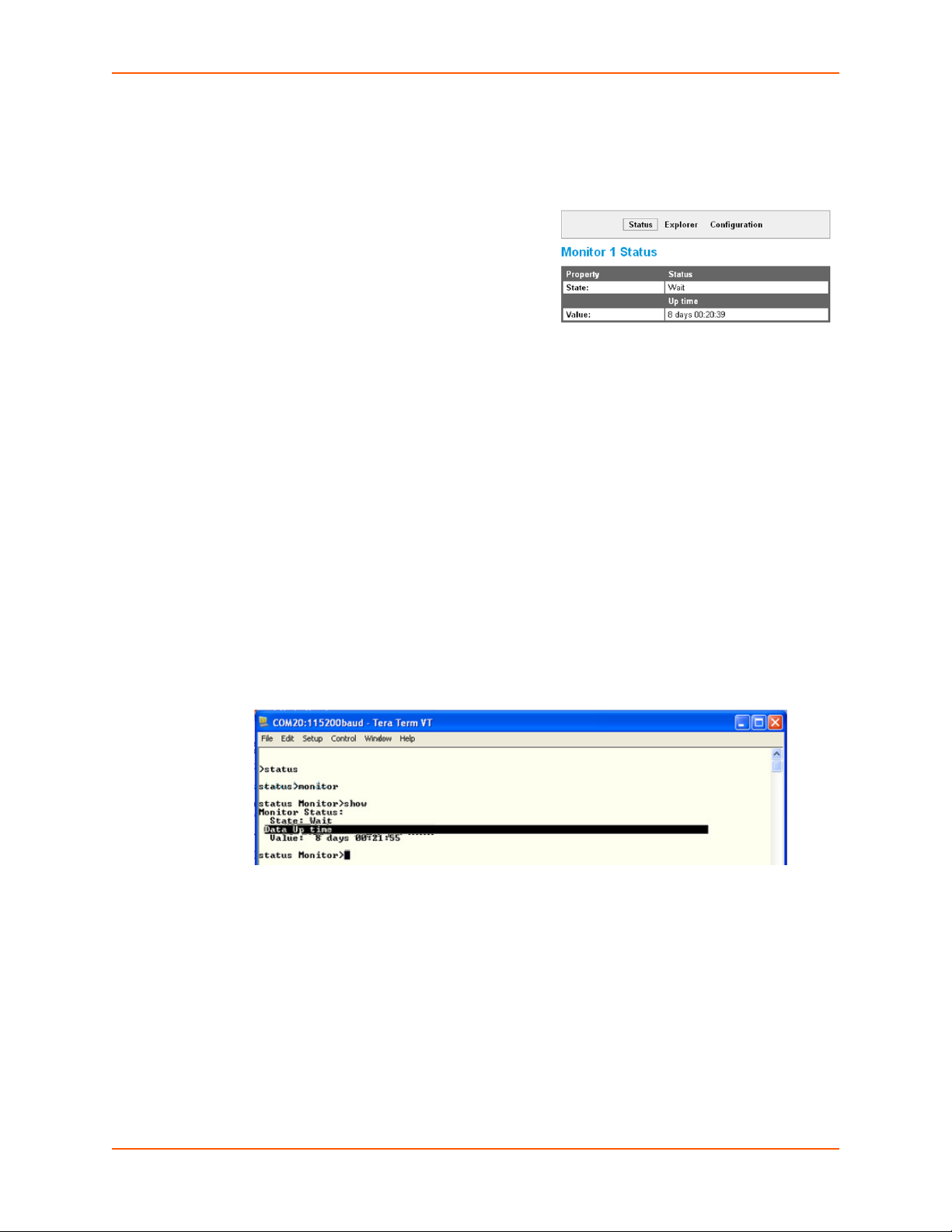
11: Monitor
Figure 11-14 Monitor Presenting
Presenting
STEP 1 - STRATEGY
Here you consider your options for sharing the data
you have mined. For human users, a Web page
presentation is simplest. For machine-to-machine
communication, XML might be best. Command Line
could be used for either.
STEP 2 - SETUP
Automatically your data is available under status on
the Web Manager, XML, and CLI.
Advanced Web customization can be done with HTML and JavaScript files dropped into the xPico
Wi-Fi unit.
STEP 3 - TEST
With the Web Manager, view all of your data under Monitor Status.
In the Command Line Interface (CLI), first type "status" to enter the status menu level, then type
"monitor" for the Monitor menu level. From there, type "show" for the data.
In the XML status dump, find statusgroup name = "Monitor", then statusitem name = "data"
instance = "<the name you gave your data>", and value contains the data received.
Sample Configuration
We visit our device Web Manager, select the "Monitor" tab at the left of the display, the select
"Status" at the top of the display. Our "Up time" and the present value appear there.
Figure 11-15 Monitor CLI Command Level
Visiting the Command Line Interface, we type "status", then "monitor", then "show". We see
"Up time" presented there.
xPico® Wi-Fi® Embedded Device Server User Guide 64
Page 65

11: Monitor
Figure 11-16 Monitor XML Commands
For XML we start at the root Command Line Interface, type "xml", then "xsr dump monitor".
We see a statusitem name = "data", instance = "Up time", with value containing the present
data.
DATA CAPTURE ON SPI
Connect xPico Wi-Fi SPI port to peripheral device, query and capture desired information
periodically, present on Web page.
xPico® Wi-Fi® Embedded Device Server User Guide 65
Page 66

12: Branding the xPico Wi-Fi Unit
This chapter describes how to brand the Web Manager user interface of your xPico Wi-Fi
embedded device server.
Web Manager Customization
Changing the Presentation
You can customize the Web Manager's appearance by modifying index.html and style.css.
The style (fonts, colors, and spacing) of the Web Manager is controlled with style.css and the
text and graphics are controlled with index.html.
The Web Manager files are hidden and are incorporated directly into the firmware image but may
be overridden by placing the appropriate file in the appropriate directory within the xPico Wi-Fi file
system.
Web Manager files can be overridden with the following procedure:
1. Either create a file from scratch, or edit a copy of the existing Lantronix file. To edit a copy of
the original file, do the following:
a. Obtain the file by entering the following path in a browser:
http://<hostname>/lantronix/resource/main/web_manager/web/<filename>
b. Then save the file (in the case of index.html, you may need to set the browser to view the
page source).
c. Modify the file as required.
2. Create a path in the file system (the entire path can be created in a single step via either the
Web Manager or CLI). The path is the same as that for the hidden files, except for the top-level
/lantronix directory:
/resource/main/web_manager/web/
3. Upload your file into the directory in step 2.
4. Restart the browser to view the changes.
To go back to the default files in the firmware image, simply delete the overriding files in the file
system (the directories can be left intact if so desired).
Path Format
As mentioned above, the root directory for hidden files built into the firmware is /lantronix. When
overriding these hidden files by placing your own copies in the file system, the path is identical but
for the /lantronix top directory. For example, the built-in hidden file /lantronix/
resource/main/web_manager/web/index.html is overridden by the real file system file
/resource/main/web_manager/web/index.html.
If you need to refer to an overridden file within your own web files, the path follows the same
format, except the /lantronix top directory of the hidden file path is replaced by /.overlay.
So, to refer to style.css from within index.html, the path in index.html is /.overlay/resource/
main/web_manager/web/index.html. This format allows the system to look first for an
overriding copy of the file before using the built-in copy.
xPico® Wi-Fi® Embedded Device Server User Guide 66
Page 67

12: Branding the xPico Wi-Fi Unit
Note: This path schema is subject to change in the future.
Other Overridable Files
In addition to index.html, and style.css, a few other presentation-related files can be overridden.
The complete list is as follows:
/resource/main/web_manager/web/index.html - Main file controlling text and graphics
/resource/main/web_manager/web/style.css - Style sheet
/resource/main/web_manager/web/img/bg.gif - Main background
/resource/main/web_manager/web/img/company_logo.gif - Company logo in header container
/resource/main/web_manager/web/img/favicon.ico - Shortcut icon
/resource/main/web_manager/web/img/header_bg.gif - Head container background
xPico® Wi-Fi® Embedded Device Server User Guide 67
Page 68

13: Updating Firmware
Obtaining Firmware
Obtain the most up-to-date firmware and release notes for the unit from the Lantronix Web site
(www.lantronix.com/support/downloads/
Loading New Firmware through Web Manager
Upload the firmware using the device Web Manager Device page.
To upload new firmware:
1. Select Device in the menu bar. The Device Status page appears.
) or by using anonymous FTP (ftp://ftp.lantronix.com/).
Note: See
debice.
Device Settings (on page 49) for options to restore factory defaults or reboot the
Figure 13-1 Uploading New Firmware
2. Click Firmware Upload.
3. Click Okay to confirm uploading a new firmware image. You will be redirected to the Firmware
Upgrade page.
4. Click Browse... to browse to the firmware file.
xPico® Wi-Fi® Embedded Device Server User Guide 68
Page 69

13: Updating Firmware
5. Select the file and click Open.
6. Click Upgrade to install the firmware on the xPico Wi-Fi embedded device server.
7. Click OK in the confirmation pop-up which appears. The firmware will be installed and the
device will automatically reboot afterwards.
8. Close and reopen the Web Manager internet browser to view the device’s updated web pages.
xPico® Wi-Fi® Embedded Device Server User Guide 69
Page 70

Appendix A: Command Reference
The xPico Wi-Fi embedded device server supports three convenient configuration methods: Web
Manager, Command Line Interface (CLI) and Extensible Markup Language (XML). This appendix
describes how to configure the xPico Wi-Fi embedded device server using the Command Line
Interface (CLI) and/or Extensible Markup Language (XML). CLI provides an interactive mode for
accessing the device configuration and management interface. It is most suited for system and
network administrators comfortable with using similar interfaces on Enterprise IT and Networking
products. It is also helpful as a quick tool for access via the product's serial ports or console/
management ports. XML provides an extensible mode for software developers.
For more information about the Web Manager, see the Chapter 3: Configuration Using Web
Manager.
Conventions
The table below lists and describes the conventions used in this book.
Convention Description
Bold text Default parameters.
Italic text Required values for parameters
Brackets [ ] Optional parameters.
Angle Brackets < > Possible values for parameters.
Pipe | Choice of parameters.
Warning Warning: Means that you are in a situation that could cause
equipment damage or bodily injury. Before you work on any
equipment, you must be aware of the hazards involved with electrical
circuitry and familiar with standard practices for preventing accidents.
Note Note: Means take notice. Notes contain helpful suggestions, information,
or references to material not covered in the publication.
Caution Caution: Means you might do something that could result in faulty
equipment operation, or loss of data.
Screen Font
(Courier New)
CLI terminal sessions and examples of CLI input.
XML Architecture and Device Control
XML is a fundamental building block for the future growth of Machine-to-Machine (M2M) networks.
The xPico Wi-Fi embedded device server supports XML configuration records that make
configuring the device server easy for users and administrators. XML configuration records are
easy to edit with a standard text editor or an XML editor.
For a brief overview of XML, see Configuration Using XML. It provides rules on basic XML syntax,
a guide to the specific XML tags used, and a guide to using XML configuration records.
xPico® Wi-Fi® Embedded Device Server User Guide 70
Page 71

Configuration Using Serial Port
Serial Command Mode
The serial port can be configured to operate in command mode permanently or to be triggered
under specified conditions. See the line <line> Level command description for more
information.
Boot to CLI
Regardless of the configured settings, the CLI can be accessed via Line 1 using fixed settings and
the "back door" procedure. The original configured line settings will be restored once the user exits
the "back door" CLI, unless any Line 1 settings are changed within the "back door" CLI.
To configure the Lantronix xPico Wi-Fi embedded device server locally using a serial port:
Note: The xPico Wi-Fi embedded device server requires that flow control be used on the
serial port to ensure the best performance when importing XML.
1. Connect a terminal or a PC running a terminal emulation program to one of the xPico Wi-Fi
embedded device server's serial ports.
2. Configure the terminal to the following settings:
Appendix A: Command Reference
9600 baud
8-bit
No parity
1 stop bit
Flow control enabled
Note: Lantronix recommends using hardware flow control.
3. Power off the device.
4. Get into the serial backdoor as follows:
a. While asserting the defaults signal,
b. Reset the device while sending X, Y, or Z characters.
c. When the incoming characters are recognized, a prompt in the following form will be seen:
xPicoWifi <MAC ADDRESS>
Note: It is important to release the defaults signal as soon as possible after the
prompt is seen; continuing to hold it down may result in a reset to factory defaults.
OR
a. While asserting the defaults signal,
b. Reset the device while sending ! character until it is echoed back.
c. Then release the defaults line, and enter xyz.
xPico® Wi-Fi® Embedded Device Server User Guide 71
Page 72

Navigating the CLI Hierarchy
The CLI is organized into a hierarchy of levels. Each level has a group of commands for a specific
purpose. For example, to view diagnostic or device status, one would navigate to the status level
where they could then navigate to diagnostics or device.
To move to a different level—Enter the name of the level from within its parent level. For
example, to enter the file system level, type file system at the enable prompt.
To exit and return to one level higher—Type exit and press the Enter key.
To view the current configuration, enter the config level by typing config.
To view the list of commands available at the current level—Type the question mark ?. Items
within < > (e.g. <string>) are required parameters.
To view the available commands and explanations—Type the asterisk (*).
To view the list of commands available for a partial command—Type the partial command
followed by the question mark "?". For example: config>? displays a list of all config
commands at the config level.
To view available commands and their explanations for a partial command—Type an asterisk
(*). For example: config Access Point>* displays a list of all accesss point commands
and descriptions at the config > access point level.
Appendix A: Command Reference
To view SPI configurations, enter the config level by typing config at the root level, and then
the SPI level by typing SPI.
To view the tlog, type tlog or t at the root level.
Using Keyboard Shortcuts and CLI
One useful shortcut built into xPico Wi-Fi embedded device server is that the complete text of a
command does not have to be entered to issue a command. Typing just enough characters to
uniquely identify a command, then hitting enter, can be used as a short cut for a command. For
example, at the enable level, "sh" can be used for the "show" command.
Tab Completion is also available using the Tab and Enter keys on the keyboard. Typing the first
few characters of a command, then hitting the Tab key displays the first command that begins with
those characters. Hitting the Tab key again displays the next command that begins with the
original characters typed. You can press Enter to execute the command or you can backspace to
edit any parameters.
The following key combinations are allowed when configuring the Pico Wi-Fi embedded device
server using the CLI:
Table A-1 Keyboard Shortcuts
Key Combination Description
Ctrl + a Places cursor at the beginning of a line
Ctrl + b Backspaces one character
Ctrl + d Deletes one character
Ctrl + e Places cursor at the end of the line
Ctrl + f Moves cursor forward one character
xPico® Wi-Fi® Embedded Device Server User Guide 72
Page 73

Key Combination (continued) Description
Ctrl + k Deletes from the current position to the end of the line
Ctrl + l Redraws the command line
Ctrl + n Displays the next line in the history
Ctrl + p Displays the previous line in the history
Ctrl + u Deletes entire line and places cursor at start of prompt
Ctrl + w Deletes one word back
Ctrl + z Exits the current CLI level
Understanding the CLI Level Hierarchy
The CLI hierarchy is a series of levels. Arranging commands in a hierarchy of levels provides a
way to organize and group similar commands, provide different levels of security, and reduce the
complexity and number commands and options presented to a user at one time.
When you start a command line session, you begin at the root level. This level can be password
protected and provides access to high level status, a few diagnostic commands, and the file
system level. Further device information and configuration are accessed via the enable level.
Appendix A: Command Reference
The enable level can also be password protected and is the gateway to full configuration and
management of the xPico Wi-Fi embedded device server. There are commands for gathering and
effecting all elements of device status and configuration, as well as commands that take you to
additional levels. For instance, tunnel specific status and configuration is found under the "tunnel"
level, and network specific status and configuration commands are found under the "configuration"
level.
Commands at the root level (see Figure A-2 Root Level Commands below) do not affect current
configuration settings and are not displayed initially. If you type ?, you will see the login subcommands. These commands provide diagnostic and status information only.
>?
config file system
help status
tlog wlan scan [network-name]
xml exit
Configuration Using XML
The xPico Wi-Fi embedded device server provides an Extensible Markup Language (XML)
interface that you can use to configure xPico Wi-Fi embedded device servers. Every configuration
setting, excluding XML import and export, that can be issued from the xPico Wi-Fi Web Manager
and CLI can be specified using XML.
Figure A-2 Root Level Commands
The XPico Wi-Fi embedded device server can import and export configuration settings as an XML
document known as an XML Configuration Record (XCR). An XCR can be imported or exported
via the CLI or the xPico Wi-Fi embedded device server filesystem. An XCR can contain many
configuration settings or just a few. For example, it might change all of the configurable
xPico® Wi-Fi® Embedded Device Server User Guide 73
Page 74

Appendix A: Command Reference
parameters for a xPico Wi-Fi embedded device server, or it may only change the baud rate for a
single serial line. Using XCRs is a straightforward and flexible way to manage the configuration of
multiple XPico Wi-Fi embedded device servers.
Note: For directions on exporting or importing XML, please refer to XML Import and
XML Export.
XML Configuration Record Document Type Definition
An XML document type definition (DTD) is a description of the structure and content of an XML
document. It verifies that a document is valid. XCRs are exported using the DTD as shown in
Figure A-3 DTD for XCRs.
Figure A-3 DTD for XCRs
<!DOCTYPE configrecord [
<!ELEMENT configrecord (configgroup+)>
<!ELEMENT configgroup (configitem+,configgroup*)>
<!ELEMENT configitem (value+)>
<!ELEMENT value (#PCDATA)>
<!ATTLIST configrecord version CDATA #IMPLIED>
<!ATTLIST configgroup name CDATA #IMPLIED>
<!ATTLIST configgroup instance CDATA #IMPLIED>
<!ATTLIST configitem name CDATA #IMPLIED>
<!ATTLIST value name CDATA #IMPLIED>
]>
The xPico Wi-Fi DTD rules state the following:
The XML document element is a <configrecord> element. This is the root element.
A <configrecord> must have one or more <configgroup> elements and can have a
version attribute.
A <configgroup> must have one or more <configitem> elements and can have name
and instance attributes.
A <configitem> element must have one or more <value> elements and can have a name
attribute.
A <value> element can have only data and can have a name attribute.
The name attribute identifies a group, item, or value. It is always a quoted string.
The instance attribute identifies the specific option, like the serial port number. The "instance"
attribute is always a quoted string.
Note:
The name for each <configgroup> (specified with the name attribute) is the group
name listed in the Web Manager XCR groups or with the "xcr list" CLI command. See
the xPico Wi-Fi Embedded Device Server User Guide for more information about the
XCR groups.
xPico® Wi-Fi® Embedded Device Server User Guide 74
Page 75

An empty or missing <value> element in each present <configgroup> clears the
setting to its default.
Quick Tour of XML Syntax
Declaration
The first line, <?xml version="1.0" standalone="yes"?>, is called the XML declaration.
It is required and indicates the XML version in use (normally version 1.0). The remainder of the file
consists of nested XML elements, some of which have attributes and content.
Element Start and End Tags
An element typically consists of two tags: start tag and an end tag that surrounds text and other
elements (element content). The start tag consists of a name surrounded by angle brackets, for
example <configrecord>. The end tag consists of the same name surrounded by angle
brackets, but with a forward slash preceding the name, for example </configrecord>. The
element content can also contain other "child" elements.
Element Attributes
The XML element attributes that are name-value pairs included in the start tag after the element
name. The values must always be quoted, using single or double quotes. Each attribute name
should appear only once in an element.
Appendix A: Command Reference
Figure A-4 shows an XML example which consists of a declaration (first line), nested elements
with attributes and content.
Figure A-4 XML Example
<configgroup name = "HTTP Server">
<configitem name = "State">
<value>Enabled</value>
</configitem>
<configitem name = "Port">
<value>80</value>
</configitem>
<configitem name = "Inactivity Timeout">
<value>5 minutes</value>
</configitem>
<configitem name = "Access Control" instance = "1">
<value name = "URI">/</value>
<value name = "AuthType">Basic</value>
<value name = "Users">admin</value>
</configitem>
</configgroup>
The xPico Wi-Fi embedded device server uses the attributes in the following subsections to label
the group configuration settings.
xPico® Wi-Fi® Embedded Device Server User Guide 75
Page 76

Record, Group, Item, and Value Tags
A <configgroup> is a logical grouping of configuration parameters and must contain one or
more <configitem> elements. It must have a name attribute and may have an instance
attribute.
A <configitem> is a specific grouping of configuration parameters relevant to its parent group.
An item takes the name attribute and must contain one or more value elements. For example, the
line group might have parameters such as baud rate, data bits, and parity.
A value may specify the value of a configuration parameter. It may contain the name attribute. In
this example, a value of 9600 might be specified for baud rate; 7 may be specified for data bits,
and even may be specified for parity
A name attribute identifies the group, item, or value. It is always quoted (as are all XML attributes).
For example,a group that contains serial port parameters has the name "line"
An instance attribute identifies which of several instances is being addressed. It is always quoted.
For example,the serial port name (in the line configgroup) has the instance "1" to indicate serial
port 1 or "2" to specify serial port 2
The following figures show examples of XML configuration records and the use of the
<configrecord>, <configgroup>, <configitem>, and <value> XML elements.
Appendix A: Command Reference
Figure A-5 XML Example
<configrecord version = "0.1.0.1">
<configgroup name = "Access Point" instance = "ap0">
<configitem name = "SSID">
<value>XpicoWiFi_98010B</value>
</configitem>
<configitem name = "Channel">
<value>1</value>
</configitem>
<configitem name = "Suite">
<value>WPA2</value>
</configitem>
<configitem name = "Encryption">
<value>CCMP</value>
</configitem>
<configitem name = "Passphrase">
<value><Configured></value>
</configitem>
<configitem name = "Mode">
<value>Always Up</value>
</configitem>
</configgroup>
xPico® Wi-Fi® Embedded Device Server User Guide 76
Page 77

Appendix A: Command Reference
XML for xPicoWi-Fi Embedded Device Server
configgroup Access Point
These settings pertain to the Access Point in the device. Changes will take effect after reboot.
configitem SSID
value
The default value of SSID is XpicoWiFi_hhhhhh, where hhhhhh are the last 6 hex digits from the BSSID.
Blank the value to restore the default.
SSID may contain up to 32 characters.
configitem Channel
value
No help available.
configitem Suite
value
Suite may be "None", "WPA" or "WPA2".
configitem Encryption
value
Encryption may contain any combination of "CCMP" or "TKIP".
configitem Passphrase
value
Passphrase may contain up to 63 characters.
The value is HIDDEN.
configitem Mode
value
Mode may be "Always Up" or "Triggered".
configitem Uptime
value
Uptime has units of seconds.
configgroup CPM
These settings pertain to the Configurable Pin Manager (CPM). Changes take effect immediately.
configitem Role
value Instance
Instance may contain up to 32 characters.
xPico® Wi-Fi® Embedded Device Server User Guide 77
Page 78

Appendix A: Command Reference
value CP
This is the number of the Configurable Pin (CP) assigned to the role.
Enter blank or 0 to revert to <No CP Selected>.
Blank the value for "<No CP Selected>".
value State
The Enabled State allows the application to use the designated Configurable Pin.
Note that some Roles (those containing a ".") are bundled into a group. Enabling / Disabling any one of
them also Enables / Disables the rest of the Roles in the same Group.
State may be "Enabled" or "Disabled".
value Assert
Assert reflects the logical polarity of this Configurable Pin.
High means that a logical "1" corresponds to a voltage high condition on the pin.
Low means that a logical "1" corresponds to a voltage low condition on the pin.
Assert may be "High" or "Low".
value Mode
Mode indicates if this Configurable Pin is set up for push-pull or if it enables an internal weak pullup.
5-Volt tolerance: In order to sustain a voltage higher than VDD+0.3, the Mode must be set to Push-Pull.
Mode may be "Push-Pull" or "Weak Pullup".
configgroup HTTP Server
These settings pertain to the HTTP Server. Changes will take effect after reboot.
configitem State
value
Enable the State to allow the HTTP Server to operate.
Disable the State to prevent HTTP from operating on any port.
State may be "Enabled" or "Disabled".
configitem Port
value
The Port can be overridden. Blank the display to restore the default.
Zero the value for "<None>".
configitem Inactivity Timeout
value
The Inactivity Timeout applies only if the Application "HTTP Server" is enabled in Performance.
The HTTP Server will hold power on this long after it completes a request.
Inactivity Timeout has units of seconds.
xPico® Wi-Fi® Embedded Device Server User Guide 78
Page 79

Appendix A: Command Reference
configitem Access Control
value URI
The URI must begin with
URI may contain up to 255 characters.
value AuthType
The different AuthType values offer various levels of security. From the least to most secure:
None
no authentication necessary
Basic
encodes passwords using Base64
There is no real reason to create an authentication directive using None unless you want to override a
parent directive that uses some other AuthType.
AuthType may be "None" or "Basic".
value Users
Users may contain up to 54 characters.
/ to refer to the file system.
configgroup Interface
These settings pertain to the Network Interface on the device. To see the effect of these selections after a
reboot, view the corresponding Status. Changes will take effect after reboot.
When an Access Point is enabled, DHCP Server will assign IP addresses to the access point's clients.
DHCP Server manages up to 4 client IP addresses (only 3 if wlan0 is enabled). The first IP Address will be
the Access Point's IP Address plus one. For example, if the Access Point's IP Address is 192.168.0.1, the
client addresses will range from 192.168.0.2 to 192.168.0.5.
configitem State
value
Enable the State to allow the Interface to operate.
State may be "Enabled" or "Disabled".
configitem DHCP Client
value
If DHCP Client is enabled, any configured IP Address, or Default Gateway will be ignored. DHCP Client
will auto-discover and eclipse those configuration items. Hostname is sent to the remote DHCP Server and
may figure into the address assignment.
When DHCP Client fails to discover an IP Address, a new address will automatically be generated using
AutoIP. This address will be within the 169.254.x.x space.
This setting is not applicable to the Access Point.
DHCP Client may be "Enabled" or "Disabled".
xPico® Wi-Fi® Embedded Device Server User Guide 79
Page 80

Appendix A: Command Reference
configitem IP Address
value
IP Address may be entered alone, in CIDR form, or with an explicit mask:
192.168.1.1 (default mask)
192.168.1.1/24 (CIDR)
192.168.1.1 255.255.255.0 (explicit mask)
The IP Address will be displayed always in CIDR, the canonical form.
IP Address may contain up to 31 characters.
configitem Default Gateway
value
The Default Gateway is used only if DHCP Client is disabled, and provides the IP Address of the router.
This setting is not applicable to the Access Point.
Default Gateway may contain up to 15 characters.
configitem Hostname
value
Hostname must begin with a letter or number, continue with letter, number, or hyphen, and must end with
a letter or number.
If DHCP Client is enabled, the Hostname is sent to the remote DHCP Server and may figure into the
address assignment.
This setting is not applicable to the Access Point.
Hostname may contain up to 63 characters.
configitem Primary DNS
value
The Primary DNS is the first choice when performing a Domain Name lookup.
This setting is not applicable to the Access Point.
Primary DNS may contain up to 15 characters.
configitem Secondary DNS
value
The Secondary DNS is the second choice when performing a Domain Name lookup.
This setting is not applicable to the Access Point.
Secondary DNS may contain up to 15 characters.
configgroup Line
These settings pertain to the Serial Line. Changes take effect immediately.
xPico® Wi-Fi® Embedded Device Server User Guide 80
Page 81

Appendix A: Command Reference
configitem Name
value
The Name is for display purposes only.
Name may contain up to 25 characters.
configitem State
value
Enable the State to allow the Serial Line to operate.
State may be "Enabled" or "Disabled".
configitem Protocol
value
Protocol selects the application to connect to the Line:
None selects no application to connect to the Line.
Tunnel sets up the Line to work with the Tunnel application. See the Tunnel configuration options for
details.
Trouble Log sets up an output-only message log on the device. Severity codes in the log are:
P Emergency
A Alert
C Critical
E Error
W Warning
N Notice
I Informational
D Debug
Command Line sets up a user interface containing commands to show device status and to change
configuration. Simply paste in XML configuration to apply its settings to the device.
Protocol may be "Command Line", "Modem Emulation", "Monitor", "None", "Trouble Log" or "Tunnel".
configitem Baud Rate
value
When specifying a Custom baud rate in the Web Manager, select '
then enter the desired rate in the text box.
Baud Rate has units of bits per second.
Custom' from the drop down list and
configitem Parity
value
Parity may be "None", "Even" or "Odd".
configitem Data Bits
value
Data Bits may be "7" or "8".
xPico® Wi-Fi® Embedded Device Server User Guide 81
Page 82

Appendix A: Command Reference
configitem Stop Bits
value
Stop Bits may be "1" or "2".
configitem Flow Control
value
Flow Control may be "None", "Hardware" or "Software".
configitem Xon Char
value
When specifying Xon Char, prefix decimal with \ or prefix hexadecimal with 0x or prefix a single control
character with <control>. These are used when Flow Control is set to Software.
Xon Char may contain one character, where <control>J, for example, counts as one.
configitem Xoff Char
value
When specifying Xoff Char, prefix decimal with \ or prefix hexadecimal with 0x or prefix a single control
character with <control>. These are used when Flow Control is set to Software.
Xoff Char may contain one character, where <control>J, for example, counts as one.
configitem Gap Timer
value
The driver forwards received serial bytes after the Gap Timer delay from the last character received. By
default, the delay is four character periods at the current baud rate (minimum 1 ms).
Gap Timer has units of milliseconds.
Blank the value for "<Four Character Periods>".
configitem Threshold
value
The driver will forward received characters after Threshold bytes have been received.
Threshold has units of bytes.
configgroup Performance
These settings pertain to Performance. Changes take effect immediately.
The device wakes up either on the rising edge of WKUP, if enabled, or after being down Maximum Time
Powered Down.
The device powers down after Time Powered Up.
However, if any Application is selected, the application may hold power on longer or wake up sooner.
configitem Application
value Instance
Instance matches the name of a registered application.
xPico® Wi-Fi® Embedded Device Server User Guide 82
Page 83

Instance may contain up to 32 characters.
value State
Enable the State to allow the named Application to hold power on.
State may be "Enabled" or "Disabled".
configitem Maximum Time Powered Down
value
Maximum Time Powered Down has units of seconds.
Blank the value for "<Infinite>".
configitem WKUP Pin Power Up
value
WKUP Pin Power Up may be "Enabled" or "Disabled".
configitem Time Powered Up
value
Time Powered Up has units of seconds.
Appendix A: Command Reference
Blank the value for "<Infinite>".
configgroup SPI
These settings pertain to the Serial Peripheral Interface (SPI) Bus Master device. Changes take effect
immediately.
configitem Name
value
The Name is for display purposes only.
Name may contain up to 25 characters.
configitem State
value
State selects the operating state of the SPI:
Enabled enables the SPI.
Disabled disables the SPI.
State may be "Enabled" or "Disabled".
configitem Protocol
value
Protocol selects the application to connect to the SPI:
None selects no application to connect to the SPI.
Monitor selects the Monitor application to connect to the SPI.
Protocol may be "None" or "Monitor".
xPico® Wi-Fi® Embedded Device Server User Guide 83
Page 84

Appendix A: Command Reference
configitem Target Speed
value
Target Speed selects the target clock speed of the SPI.
The Target Speed may be lowered to the closest Operating Speed capability of the device. If so, a
warning will be noted.
0 or clearing the selection selects the minimum speed.
Target Speed has units of Hz.
Blank the value for "<Minimum>".
configitem Idle Clock Level
value
Idle Clock Level, also known as Clock Polarity or CPOL, selects the level of the clock when idle:
Low means the idle clock is at a low level. This is equivalent to CPOL=0.
High means the idle clock is at a high level. This is equivalent to CPOL=1.
Idle Clock Level may be "Low" or "High".
configitem Clock Edge
value
Clock Edge, also known as Clock Phase or CPHA, selects the clock edge for latching data:
First means each bit is latched on the first edge of the clock. This is equivalent to CPHA=0. When Idle
Clock Level is Low, data is latched on the rising edge. When Idle Clock Level is High, data is latched on
the falling edge.
Second means each bit is latched on the second edge of the clock. This is equivalent to CPHA=1. When
Idle Clock Level is Low, data is latched on the falling edge. When Idle Clock Level is High, data is
latched on the rising edge.
Clock Edge may be "First" or "Second".
configitem Bits Per Word
value
Bits Per Word selects the number of bits per word of transfer.
Bits Per Word may be "8" or "16".
configitem First Transfer
value
First Transfer selects the first transfer bit of each word.
First Transfer may be "Most Significant Bit" or "Least Significant Bit".
configgroup Users
These settings pertain to Users on the device.
xPico® Wi-Fi® Embedded Device Server User Guide 84
Page 85

Appendix A: Command Reference
configitem Instance
value
Instance may contain up to 16 characters.
configitem Password
value
Password may contain up to 32 characters.
The value is HIDDEN.
configgroup WLAN Profile
These settings pertain to a WLAN Profile on the device.
In the Security section, choice of Suite, Key Type and Authentication affect the makeup of other
configurables in that section.
In the Advanced section, if Power Management is enabled, specify the Power Management Interval.
Use the Apply button to try out settings on the WLAN without saving them to Flash. If the settings do not
work, when you reboot the device, it will still have the original settings.
Use the Submit button to both update the WLAN settings and save them to Flash.
If the device is connecting to an acess point on a different wireless channel, current connection to the soft
AP interface of the device may be dropped due to the switch of channel. Reconnect to the soft AP interface
in order to continue access to the device.
configitem Instance
value
Instance may contain up to 35 characters.
configitem Basic
value Network Name
Network Name may contain up to 32 characters.
value State
State may be "Enabled" or "Disabled".
configitem Security
value Suite
Suite may be "None", "WEP", "WPA" or "WPA2".
value WEP Key Size
Key Size may be "40" or "104".
value WEP TX Key Index
TX Key Index may be "1", "2", "3" or "4".
value WEP Key Key
Key may contain up to 13 bytes.
xPico® Wi-Fi® Embedded Device Server User Guide 85
Page 86

The value is HIDDEN.
value WPAx Key Type
Key Type may be "Passphrase" or "Hex".
value WPAx Passphrase
Passphrase may contain up to 63 characters.
The value is HIDDEN.
value WPAx Key
Key may contain up to 32 bytes.
The value is HIDDEN.
value WPAx Encryption
Encryption may contain any combination of "CCMP" or "TKIP".
configitem Advanced
value TX Power Maximum
TX Power Maximum has units of dBm.
value Power Management
Appendix A: Command Reference
Power Management may be "Enabled" or "Disabled".
value Power Management Interval
Power Management Interval has units of beacons (100 ms each).
configgroup XML Import Control
No help available.
configitem Restore Factory Configuration
value
Restore Factory Configuration may be "Enabled" or "Disabled".
configitem Reboot
value
Reboot may be "Enabled" or "Disabled".
configitem Missing Values
value
Missing Values may be "Unchanged" or "Set to Default".
configitem Delete WLAN Profiles
value
Delete WLAN Profiles may be "Enabled" or "Disabled".
xPico® Wi-Fi® Embedded Device Server User Guide 86
Page 87

Appendix A: Command Reference
configitem WLAN Profile delete
value name
name may contain up to 35 characters.
configgroup Modem Emulation
Connections can be initiated and accepted using Modem "AT" commands incoming from the Serial Line.
configitem Listen Port
value
Specify a Listen Port to accept connections on.
Blank the value for "<None>".
configitem Echo Pluses
value
With Echo Pluses enabled, pluses will be echoed back during a "pause +++ pause" escape sequence on the
Serial Line.
Echo Pluses may be "Enabled" or "Disabled".
configitem Echo Commands
value
With Echo Commands enabled (ATE1), characters read on the Serial Line will be echoed while the Line
is in Modem Command Mode.
Echo Commands may be "Enabled" or "Disabled".
configitem Verbose Response
value
With Verbose Reponse enabled (ATQ0), Modem Response Codes are sent out on the Serial Line.
Verbose Response may be "Enabled" or "Disabled".
configitem Response Type
value
Response Type selects either Text (ATV1) or Numeric (ATV0) representation for the Modem Response
Codes sent out on the Serial Line.
Response Type may be "Text" or "Numeric".
configitem Error Unknown Commands
value
With Error Unknown Commands enabled (ATU0), ERROR is returned on the Serial Line for
unrecognized AT commands. Otherwise (ATU1) OK is returned for unrecognized AT commands.
Error Unknown Commands may be "Enabled" or "Disabled".
xPico® Wi-Fi® Embedded Device Server User Guide 87
Page 88

Appendix A: Command Reference
configitem Incoming Connection
value
Incoming Connection requests may be disabled (ATS0=0), answered automatically (ATS0=1), or
answered manually via the ATA command after an incoming RING (ATS0=2 or higher).
Incoming Connection may be "Disabled", "Automatic" or "Manual".
configitem Connect String
value
The Connect String is a customized string that is sent to the Serial Line with the CONNECT Modem
Response Code.
Connect String may contain up to 30 characters.
configitem Display Remote IP
value
With Display Remote IP enabled, the incoming RING sent on the Serial Line is followed by the IP
address of the caller.
Display Remote IP may be "Enabled" or "Disabled".
configgroup Monitor Initialization
These settings pertain to Monitor Initialization in the device.
Monitor will process any initialization message before it starts polling or process any control message.
Response captured during initialization will be overwritten by any poll or control response.
configitem Initial Delay
value
Sets Initial Delay waited before monitor start processing any initialization message.
Initial Delay has units of milliseconds.
configitem Message
value Command
Sets the Command in binary format.
Binary format takes printable characters (e.g. 'abc' for characters 'a', 'b' and 'c') or binary string (e.g. [0xa,
0xd] for line feed and carriage return).
Command may contain up to 16 bytes.
value End Character
Sets the End Character to indicate end of response.
Response is ended by any configured End Character, Length OR Timeout.
The End Character may be designated as a single printable character or as a control character.
Control characters may be input in any of the following forms:
<control>J
0xA (hexadecimal)
xPico® Wi-Fi® Embedded Device Server User Guide 88
Page 89

Appendix A: Command Reference
\10 (decimal)
End Character may contain one character, where <control>J, for example, counts as one.
value Length
Sets the Length of response.
Response is ended by any configured End Character, Length OR Timeout.
Length has units of bytes.
value Timeout
Sets the Timeout to receive response. Minimum timeout is 100 milliseconds.
Response is ended by any configured End Character, Length OR Timeout.
Timeout has units of milliseconds.
Blank the value for "<Minimum>".
configgroup Monitor Control
These settings pertain to Monitor Control in the device.
Control Message will be processed after receiving status action Send. Response will overwrite any
response captured during initialization or poll. Response must be read before sending another status action
Send or buffer will be reset.
configitem Message
value Command
Sets the Command in binary format.
Binary format takes printable characters (e.g. 'abc' for characters 'a', 'b' and 'c') or binary string (e.g. [0xa,
0xd] for line feed and carriage return).
Command may contain up to 16 bytes.
value End Character
Sets the End Character to indicate end of response.
Response is ended by any configured End Character, Length OR Timeout.
The End Character may be designated as a single printable character or as a control character.
Control characters may be input in any of the following forms:
<control>J
0xA (hexadecimal)
\10 (decimal)
End Character may contain one character, where <control>J, for example, counts as one.
value Length
Sets the Length of response.
Response is ended by any configured End Character, Length OR Timeout.
Length has units of bytes.
xPico® Wi-Fi® Embedded Device Server User Guide 89
Page 90

Appendix A: Command Reference
value Timeout
Sets the Timeout to receive response. Minimum timeout is 100 milliseconds.
Response is ended by any configured End Character, Length OR Timeout.
Timeout has units of milliseconds.
Blank the value for "<Minimum>".
configgroup Monitor Poll
These settings pertain to Monitor Poll in the device.
Poll Message will be processed periodically. Response will overwrite any response captured during
initialization or poll.
configitem Message
value Command
Sets the Command in binary format.
Binary format takes printable characters (e.g. 'abc' for characters 'a', 'b' and 'c') or binary string (e.g. [0xa,
0xd] for line feed and carriage return).
Command may contain up to 16 bytes.
value End Character
Sets the End Character to indicate end of response.
Response is ended by any configured End Character, Length OR Timeout.
The End Character may be designated as a single printable character or as a control character.
Control characters may be input in any of the following forms:
<control>J
0xA (hexadecimal)
\10 (decimal)
End Character may contain one character, where <control>J, for example, counts as one.
value Length
Sets the Length of response.
Response is ended by any configured End Character, Length OR Timeout.
Length has units of bytes.
value Timeout
Sets the Timeout to receive response. Minimum timeout is 100 milliseconds.
Response is ended by any configured End Character, Length OR Timeout.
Timeout has units of milliseconds.
Blank the value for "<Minimum>".
configitem Delay
value
Sets Delay waited before monitor starts processing all poll messages again. 0 means poll messages are sent
xPico® Wi-Fi® Embedded Device Server User Guide 90
Page 91

Appendix A: Command Reference
only once.
Delay has units of seconds.
configgroup Monitor Filter
These settings pertain to Monitor Filter in the device.
Filter settings will be applied to all received response. Filter results can be used to feed another filter or use
as Data Reference.
configitem Rule
value Source
Sets the Source in dot number format.
Source defines the input of a filter. E.g. If the source of this Filter is the second trunk of data created by
filter 1, Source must be set to "1.2". A Source of "0" indicates the raw response.
Dot number format could be "0" or two numbers separated by a dot (e.g. "1.2").
Source may contain up to 6 characters.
value Mode
Sets filter Mode.
All makes filter ouput to be a duplicate of input.
Delimiters filter breaks input up to 8 trunks separated by Binary String. Each trunk will not contain the
delimiters.
Binary filter breaks input into 3 trunks according to Offset and Length.
Mode may be "All", "Delimiters" or "Binary".
value Delimiter Binary String
Sets Binary String delimiter in binary format.
Delimiters break input up to 8 trunks separated by (but not containing) delimiters. A delimiter is
recognized if any of the Binary String is completely matched.
Binary format takes printable characters (e.g. 'abc' for characters 'a', 'b' and 'c') or binary string (e.g. [0xa,
0xd] for line feed and carriage return).
Binary String may contain up to 6 bytes.
value Start Index
Sets Start Index to indicate when Delimiters filter starts breaking input into trunks.
value Offset
Sets Offset for the size of the first trunk of data created by Binary Filter.
Offset has units of bytes.
value Length
Sets Length for the size of the second trunk of data created by Binary Filter. The third trunk of data
created by Binary Filter will contain the rest of input.
Length has units of bytes.
xPico® Wi-Fi® Embedded Device Server User Guide 91
Page 92

Appendix A: Command Reference
configgroup Monitor Data
These settings pertain to Monitor Data in the device.
Data configured here will be accessible through the status of Monitor.
configitem Selector
value Name
Sets Name to enable the data selector.
Name may contain up to 16 characters.
value Response
Sets Response instance to select the source of data. Response instance corresponds to Poll or Control
Message instance.
Blank the value for "<None>".
value Reference
Sets the Reference in dot number format.
Reference selects the output of Monitor Filter. E.g. If data should select the second trunk of data created
by filter 1, Reference must be set to "1.2". A Reference of "0" indicates the raw response.
Dot number format could be "0" or two numbers separated by a dot (e.g. "1.2").
Reference may contain up to 6 characters.
configgroup Tunnel Accept
Tunnel Accept Mode controls how a tunnel behaves when a connection attempt originates from the
network.
configitem Mode
value
An Accept Tunnel can be started in a number of ways, according to its Mode:
Disabled: never started.
Always: always started.
Any Character: started when any character is read on the Serial Line.
Start Character: started when the Start Character is read on the Serial Line.
Modem Control Asserted: started when the Modem Control pin is asserted on the Serial Line.
Mode may be "Disable", "Always", "Any Character", "Start Character" or "Modem Control Asserted".
configitem Local Port
value
The Local Port value can be overridden. By default, it is 10001 for Tunnel 1, 10002 for Tunnel 2, and so
on.
Blank the display field to restore the default.
xPico® Wi-Fi® Embedded Device Server User Guide 92
Page 93

Appendix A: Command Reference
configitem Protocol
value
The Protocol used on the connection can be TCP.
Protocol may be "TCP".
configitem Start Character
value
When the Start Character is received on the Serial Line, it enables the tunnel to listen for a network
connection.
The Start Character may be designated as a single printable character or as a control character.
Control characters may be input in any of the following forms:
<control>J
0xA (hexadecimal)
\10 (decimal)
Start Character may contain one character, where <control>J, for example, counts as one.
configitem Flush Start Character
value
Enabling Flush Start Character prevents forwarding of a start character from the Line into the network.
Disabling Flush Start Character allows forwarding of a start character from the Line into the network.
Flush Start Character may be "Enabled" or "Disabled".
configitem Flush Line
value
Flush Line applies at the time when a connection is accepted from the network.
If Enabled, any buffered characters from the Serial Line will be discarded when a connection is accepted.
If Disabled, any characters received on the Serial Line will be buffered and sent after a connection is
accepted.
Flush Line may be "Enabled" or "Disabled".
configitem Block Line
value
Block Line may be enabled for debugging purposes.
If Enabled, incoming characters from the Serial Line will NOT be forwarded to the network. Instead, they
will be buffered and will eventually flow off the Serial Line if hardware or software flow control is
configured.
If Disabled (the normal setting), incoming characters from the Serial Line are sent on into the network.
Any buffered characters are sent first.
Block Line may be "Enabled" or "Disabled".
xPico® Wi-Fi® Embedded Device Server User Guide 93
Page 94

Appendix A: Command Reference
configitem Block Network
value
Block Network may be enabled for debugging purposes.
If Enabled, incoming characters from the network will NOT be forwarded to the Serial Line. Instead, they
will be buffered and will eventually flow off the network side.
If Disabled (the normal setting), incoming characters from the network are sent on into the Serial Line.
Any buffered characters are sent first.
Block Network may be "Enabled" or "Disabled".
configitem Password
value
The Password can be up to 31 characters in length and must contain only alphanumeric characters and
punctuation. When set, clients must send the correct password string to the unit within 30 seconds from
opening network connection in order to enable data transmission. The password sent to the unit must be
terminated with one of the following:
0A (Line Feed)
00 (Null)
0D 0A (Carriage Return / Line Feed)
0D 00 (Carriage Return / Null)
If Prompt for Password is set to Enabled, the user will be prompted for the password upon connection.
Password may contain up to 31 characters.
The value is HIDDEN.
configitem Prompt for Password
value
Prompt for Password may be "Enabled" or "Disabled".
configgroup Tunnel Line
The Line Configuration applies to the Serial Line interface.
See also the Line
configitem DTR
value
The DTR options select the conditions in which the Data Terminal Ready control signal on the Serial
Line is asserted.
configuration.
The DTR option Asserted while connected causes DTR to be asserted whenever either a connect or an
accept mode tunnel connection is active.
DTR may be "Asserted while connected", "Continuously asserted" or "Unasserted".
xPico® Wi-Fi® Embedded Device Server User Guide 94
Page 95

Appendix A: Command Reference
configgroup Tunnel Connect
Tunnel Connect controls how a tunnel behaves when a connection attempt originates locally.
configitem Mode
value
A Connect Tunnel can be started in a number of ways, according to its Mode:
Disabled: never started.
Always: always started.
Any Character: started when any character is read on the Serial Line.
Start Character: started when the Start Character is read on the Serial Line.
Modem Control Asserted: started when the Modem Control pin is asserted on the Serial Line.
Mode may be "Disable", "Always", "Any Character", "Start Character" or "Modem Control Asserted".
configitem Start Character
value
When the Start Character is received on the Serial Line, it connects the tunnel.
The Start Character may be designated as a single printable character or as a control character.
Control characters may be input in any of the following forms:
<control>J
0xA (hexadecimal)
\10 (decimal)
Start Character may contain one character, where <control>J, for example, counts as one.
configitem Flush Start Character
value
Enabling Flush Start Character prevents forwarding of a start character from the Line into the network.
Disabling Flush Start Character allows forwarding of a start character from the Line into the network.
Flush Start Character may be "Enabled" or "Disabled".
configitem Local Port
value
The Local Port is by default random but can be overridden.
Blank the field to restore the random default.
Blank the value for "<Random>".
configitem Host
value Address
The Host Address is required to enable a Connect Tunnel.
It designates the address of the remote host to connect to.
Either a DNS address or an IP address may be provided.
Address may contain up to 50 characters.
xPico® Wi-Fi® Embedded Device Server User Guide 95
Page 96

Appendix A: Command Reference
value Port
The Host Port is required to enable a Connect Tunnel.
It designates the TCP port on the remote host to connect to.
Blank the value for "<None>".
value Protocol
The Protocol used on the connection can be TCP.
Protocol may be "TCP".
configitem Connections
value
Connections controls how multiple hosts shall be used with a Connect Tunnel.
With Sequential selected, when it is time for the tunnel to connect, it will start with host 1 and attempt
each host in sequence until a connection is accepted.
With Simultaneous selected, when it is time for the tunnel to connect, it will connect to all of the hosts that
accept a connection.
Connections may be "Sequential" or "Simultaneous".
configitem Reconnect Time
value
The Reconnect Time specifies how long to wait in seconds before trying to reconnect to the remote host
after a previous attempt failed or the connection was closed.
Blank the display field to restore the default.
Reconnect Time has units of seconds.
configitem Flush Line
value
Flush Line applies at the time when a connection is established to the network.
If Enabled, any buffered characters from the Serial Line will be discarded when a connection is
established.
If Disabled, any characters received on the Serial Line will be buffered and sent after a connection is
established.
Flush Line may be "Enabled" or "Disabled".
configitem Block Line
value
Block Line may be enabled for debugging purposes.
If Enabled, incoming characters from the Serial Line will NOT be forwarded to the network. Instead, they
will be buffered and will eventually flow off the Serial Line if hardware or software flow control is
configured.
If Disabled (the normal setting), incoming characters from the Serial Line are sent on into the network.
Any buffered characters are sent first.
Block Line may be "Enabled" or "Disabled".
xPico® Wi-Fi® Embedded Device Server User Guide 96
Page 97

Appendix A: Command Reference
configitem Block Network
value
Block Network may be enabled for debugging purposes.
If Enabled, incoming characters from the network will NOT be forwarded to the Serial Line. Instead, they
will be buffered and will eventually flow off the network side.
If Disabled (the normal setting), incoming characters from the network are sent on into the Serial Line.
Any buffered characters are sent first.
Block Network may be "Enabled" or "Disabled".
configgroup Tunnel Disconnect
These settings relate to Disconnecting a Tunnel.
configitem Stop Character
value
When the Stop Character is received on the Serial Line, it disconnects the tunnel.
The Stop Character may be designated as a single printable character or as a control character.
Control characters may be input in any of the following forms:
<control>J
0xA (hexadecimal)
\10 (decimal)
Disable the Stop Character by blanking the field to set it to <None>.
Stop Character may contain one character, where <control>J, for example, counts as one.
configitem Flush Stop Character
value
Enabling Flush Stop Character prevents forwarding of a stop character from the Line into the network.
Disabling Flush Stop Character allows forwarding of a stop character from the Line into the network.
Flush Stop Character may be "Enabled" or "Disabled".
configitem Modem Control
value
Modem Control enables disconnect when the Modem Control pin is not asserted on the Serial Line.
Modem Control may be "Enabled" or "Disabled".
configitem Timeout
value
Timeout enables disconnect after the tunnel is idle for a specified number of milliseconds. The value of
zero disables the idle timeout.
Timeout has units of milliseconds.
Blank the value for "<Disabled>".
xPico® Wi-Fi® Embedded Device Server User Guide 97
Page 98

Appendix A: Command Reference
configitem Flush Line
value
Flush Line enabled will flush the Serial Line when the Tunnel is disconnected.
Flush Line may be "Enabled" or "Disabled".
configgroup Tunnel Packing
When Tunneling, instead of sending data on the network immediately after being read on the Serial Line,
the data can be Packed (queued) and sent in larger chunks.
configitem Mode
value
A Tunnel can be configured to use Packing Mode in the following ways:
Disable: data not packed.
Timeout: data sent after timeout occurs.
Send Character: data sent when the Send Character is read on the Serial Line.
Mode may be "Disable", "Timeout" or "Send Character".
configitem Timeout
value
If the oldest byte of queued data has been waiting for Timeout milliseconds, the queued data will be sent
on the network immediately.
Timeout has units of milliseconds.
configitem Threshold
value
If the number of bytes of queued data reaches the Threshold, the queued data will be sent on the network
immediately.
Threshold has units of bytes.
configitem Send Character
value
If used, the Send Character is a single printable character or a control character that, when read on the
Serial Line, forces the queued data to be sent on the network immediately.
Control characters may be input in any of the following forms:
<control>J
0xA (hexadecimal)
\10 (decimal)
Send Character may contain one character, where <control>J, for example, counts as one.
xPico® Wi-Fi® Embedded Device Server User Guide 98
Page 99

Appendix A: Command Reference
configitem Trailing Character
value
The Trailing Character is an optional single printable character or control character that is injected into
the outgoing data stream right after the Send Character.
Control characters may be input in any of the following forms:
<control>J
0xA (hexadecimal)
\10 (decimal)
Disable the Trailing Character by blanking the field to set it to <None>.
Trailing Character may contain one character, where <control>J, for example, counts as
one.
xPico® Wi-Fi® Embedded Device Server User Guide 99
Page 100

Appendix B: WebAPI
WebAPI is a cloud function API allowing access to configuration and status information of xPico
Wi-Fi embedded device server through standard HTTP request.
Export Status Group
An HTTP POST request can be sent to the device to retrieve status information.
Protocol: HTTP
Method: Post
URL: http://<hostname>/export/status
Parameters:
optionalLine: Optional line index for line oriented XML groups
optionalGroupList: Optional list of XML groups separated by semicolon. If omitted, all status
groups will be returned.
CURL example:
curl -u admin:PASSWORD http://172.19.100.125/export/status -X POST
curl -u admin:PASSWORD http://172.19.100.125/export/status -X POST -d
"optionalGroupList=Device"
Javascript example:
myXmlhttprequest.open(
"POST",
"/export/status",
true
);
request.send(
"optionalGroupList=Device"
);
Export Configuration Group
An HTTP POST request can be sent to the device to retrieve configuration information.
Protocol: HTTP
Method: Post
URL: http://<hostname>/export/config
Parameters:
optionalLine: Optional line index for line oriented XML groups
optionalGroupList: Optional list of XML groups separated by semicolon. If omitted, all
configuration groups will be returned.
xPico® Wi-Fi® Embedded Device Server User Guide 100
 Loading...