

Page 1

LP575G_UG_ENB01W
LP-575G
54MB High Power Wireless USB Adapter
Installation Guide
LanPro, The natural choice in Networking and LanProfessional are US registered Brands.
LanPro ( L anProfessi on a l) products are made in on e of t h e followin g Coun tries: USA, Taiwan, Thailand,
China, and Canada. The exact country of origin is unknown
1
Page 2

COPYRIGHT & TRADEMARKS
Specifications are subject to change without notice LanPro Inc. Copyright ©
2008 LanPro Inc. All rights reserved. Other brands and product names are
trademarks or registered trademarks of their respective holders.
No part of the specifications may be reproduced in any form or by any means
or used to make any derivative such as translation, transformation, or
adaptation without permission from LanPro Inc. Copyright © 2008 LanPro Inc.
All rights reserved.
FCC STATEMENT
This equipment has been tested and found to comply with the limits for a class
B digital device, pursuant to part 15 of the FCC Rules. These limits are
designed to provide reasonable protect i o n ag a inst harmfu l inte r fe re nce in a
res ide nt i a l insta ll ati o n.
This equipment generates, uses and can radiate radio frequency energy and, if
not installed and used in accordance with the instructions, may cause harmful
interference to radio communications. However, there is no guarantee that
interference will not occur in a particular installation. If this equipment does
cause harmful interference to radio or television reception, which can be
determined by turning the equipment off and on, the user is encouraged to try
to co rrect the interference by one or more of the foll owing measures:
• Reorient or relocate the receiving antenna.
• Increase the separation between the equipment and receiver.
• Connect the equipment into an outlet on a circuit different from that to
whi ch the receiver is connected.
• Consult the dealer or an experienced radio/TV technician for help.
2
Page 3

This device complies with Part 15 of the FCC Rules. Operation is subject to the
fo llowing two condi tions:
1. This device may not cause harmful interference.
2. This device must accept any interference received, including
interference that may cause undesired operation.
Changes or modifications to this unit not expressly approved by the party
responsible for compliance could void the user's authority to operate the
equipment.
FCC RF Radiation Exposure Statement:
This equipment complies with FCC RF radiation exposure limits set forth for an
uncontrolled environment. This device and its antenna must not be co-located
or operating in conjunction with any other antenna or transmitter.
IMPORTANT NOTE:
FCC Radiati on Exposur e Sta tement:
This devi ce has been tested fo r compliance with FCC RF E xposure (SAR) limit s
in the typical laptop computer configuration and this device can be used in
substantially similar laptop computers with side mounted PCMCIA slots. This
device cannot be used with handheld PDAs (personal digital assistants) or
other portable host devices. This device and its antenna must not be
co-locat ed or op e r ate d in co nj u nc ti o n wit h any othe r ant e n na or transmitter.
CE Declaration of Conformity
For the following equipment: LP-575G
Is here with confirmed to comply with the requirements set out in the Council
Directive on the Approximation of th e La ws of the Membe r States r ela ting to
Electromagnetic Compatibility (89/336/EEC), Low-voltage Directive
3
Page 4

(73 /23/EEC) and t he A men dment Di recti ve ( 93/68 /EEC), th e proced ur es gi ven
in European Council Directive 99/5/EC and 89/3 36 0 EE C.
The equipment was passed. The test was performed according to the following
European standards:
• EN 300 32 8 V. 1. 4.1 (20 03).
• EN 301 48 9-1 V.1.4.1 (2002) / EN 301 489-17 V.1.2.1 (2002).
• EN 60950-1: 20 01.
European standards dictate maximum radiated transmit power of 100mW EIRP
and frequency range 2.400-2.4835GHz; In France, the equipment must be
restricted to the 2.4465-2.4835GHz frequency range and must be restricted to
indoor use .
4
Page 5

CONTENT
Pack ag e Co nt e nts .................................................................................................................... 6
Chapter 1: Introduction ......................................................................................................... 6
1.1 Over v iew of the product ........................................................................................... 6
1.2 Features .......................................................................................................................... 7
1.2 LED Status ..................................................................................................................... 7
Chapter 2: Installat io n Gu id e .............................................................................................. 8
2.1 Software Installation ................................................................................................. 8
2.1.1 Overview ................................................................................................................. 8
2.1.2 Softw ar e Ins tall at i o n for Wi nd ow s 200 0 ................................................... 8
2.2 Hardware Installation .............................................................................................. 11
2.3 Uninstall Software .................................................................................................... 12
2.3.1 Uninstall the driver software from your PC ............................................... 12
Capítulo 3: Configuración ................................................................................................... 13
3.1 Profile ........................................................................................................................... 14
3.1.1 Add or Edit a Conf iguration Pr o fi le .............................................................. 16
3.2 Link Status .................................................................................................................. 19
3.3 Si te Survey ................................................................................................................. 20
3.4 Statistics ................................................................................................................... 20
3.5 Advanced ..................................................................................................................... 21
3.6 About ............................................................................................................................ 22
3.7 An example for application .................................................................................... 23
Appendix A: Specifi cations ................................................................................................. 24
Appendix B: Glossary ........................................................................................................... 25
App e ndix C: Cont ac t I nf or m at i o n ..................................................................................... 27
5
Page 6

Package Contents
The following contents should be found in your box:
• One LP -575 G USB Wireless Adapter
• One USB extension cable
• Quick Ins t a ll at i o n G uide
• One LP -575 G Wireless Ada pter Resource CD, includin g:
Utility and Drivers
User Guide
Other Helpful Information
Note: If any o f the listed contents is damaged or missing, please contact the
retailer from whom you purchased
Chapter 1: Introducti on
1.1 Over view of th e pr oduct
The LANPRO LP-575G USB Wireless Adapter gives you the flexi bility to install
your PC or notebook PC in the most convenient location available, without the
cost of running the network cables.
Its auto-sensing capability allows high packet transfer up to 54Mbps for
maximum throughput, or dynamic range shifting to lower speeds due to
distance or operating limitations in an environment with a lot of
electro magnetic interferen ce. It can al so intero perate with all 11Mbps wi reless
(802.11b) products. Your wireless communications are protected by up to 128bit WEP and WPA encryption, so your data stays secure.
6
Page 7

1.2 Features
• Complies with IEEE802.11g, IEEE802.11b standards
• Supports WPA data security, IEEE802.1x authentication, TKIP/AES
encryption, 64/128-bit WEP encryption
• Supports 54/48/36/24/18/12/9/6Mbps or 11/5.5/3/2/1Mbps wireless
LAN data transfer rates
• Provides USB interface
• Supports Ad-Hoc and Infrastructure modes
• Supports roaming between access points when configured in
Infrastructure mode
• Eases conf ig urati o n and pr o vid e s monit or i ng i nf ormation
• Supports Windows 98SE, Me, 2000, XP, Vista and Linux, Macintosh
• Internal Antenna
1.2 LED Status
The LED on the top of this card indicates Link/Act status. It blinks at green
light when sending and receiving data.
7
Page 8

Chapter 2: Install at i o n Gui de
2.1 Software Installation
2.1.1 Overview
The 575G Setup Wizard will guide you through the installation procedure for
Windows 98SE, Me, 2000, XP, Vista and Linux, Macintosh. The Setup Wizard
will guide you install the Utility and drivers.
If you install th e hardware before the software, you will be prompted “Found
New Hardware Wizard”, click the Cancel button, and run the Setup Wizard
program on the CD-ROM.
The Setup steps for Windows 98SE, Me, 2000, XP, Vista and Linux, Macintosh
are very similar. The following setup steps are for windows 2000.
2.1.2 Software Installation for Windows 2000
1. Insert the Resource CD into your CD-ROM dri ve, click th e Start button
and choose Run. In the field that appears, enter F:\XXX\Setup.exe (if
“F” is the l etter of your CD-ROM drive; XXX presents the setup program
path, which is labeled on the Resource CD), figure 2-1 should then
appear.
2. You can click the Cancel button to end the installation on the Preparing
Setup screen, figure 2-1. Otherwise, the Setup Wizard will display a
screen similar to that shown in figure 2-2 after a moment.
8
Page 9

Figur e 2-1 Preparing Setup
3. To continue, click the Next button on the screen, figure 2-2. Cli ck t he
Cancel button to end the Installation.
Figur e 2-2 Start Setup
4. Click Browse to change the destination location for the software in
figure 2 -3 Click Next to continue the Installation.
9
Page 10
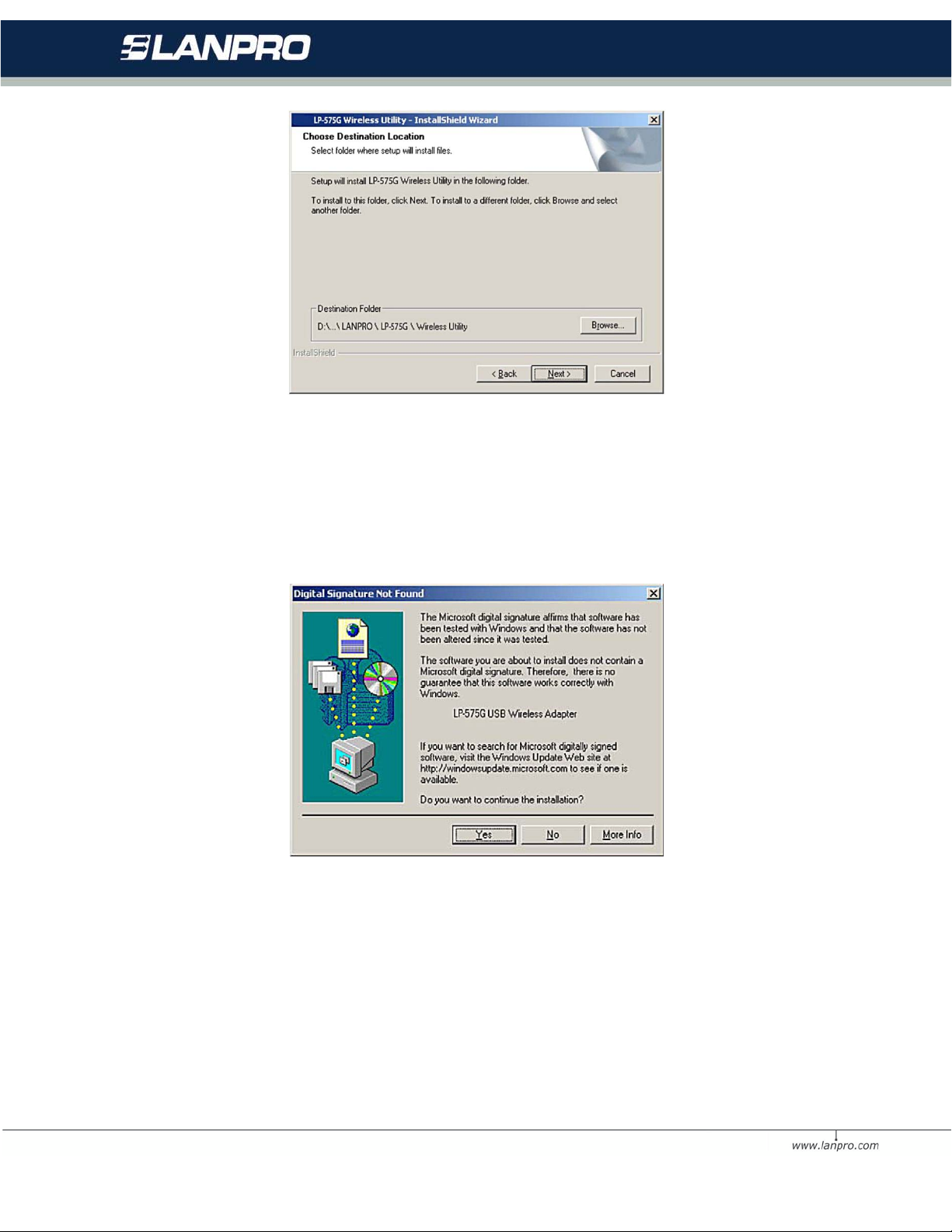
Figur e 2-3 C h oose De sti nati on Loc a ti on
5. While files are copying, you will see a warning box shown in figure 2-4.
Pleas e select YES to continu e install ation. Our dr ivers ha ve been tested
thoroughly, and are able to work with the operating system.
Figur e 2-4 Windows 2000 Warning Box
6. After the files have been succ essfully copi ed , the screen in figure 2-5 will
appear. Click the Finish button to finish the wizard.
10
Page 11
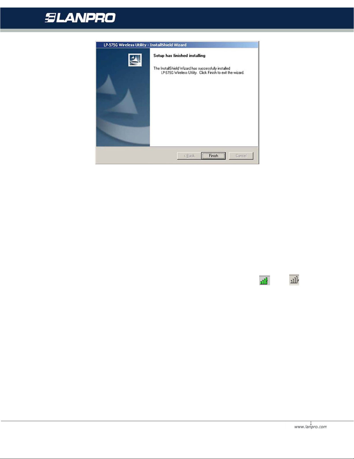
Figure 2-5 Finish
7. After installing the software, Please plug the adapter into your PC. If you
need instructions as to how to do this, please refer to section 2.2
Hardware Installation. If you have plugged it into you PC alrea dy, please
un-plug it and plug it back in. The OS will automatically detect the
adapter and automatically setup the driver for the adapter. If it does
not, please follow the setup steps to finish the driver installation.
After installing the driver successfully, you should see an icon , or ,
appear in your system tray.
2.2 Hardware Installation
1. Con nec t one en d of th e U SB cab le t o the Ad apt er. (Or th e 575 G direc tl y
to the USB computer port).
2. Connect the other end of the USB cable to the USB port on your
computer. Because the Adapter gets its power from the host, there is no
external power supply. The LED should light up when the Adapter is
plugged in and the PC is on.
11
Page 12
2.3 Uninstall Software
2.3.1 Uninstall the drive r sof tware from your PC
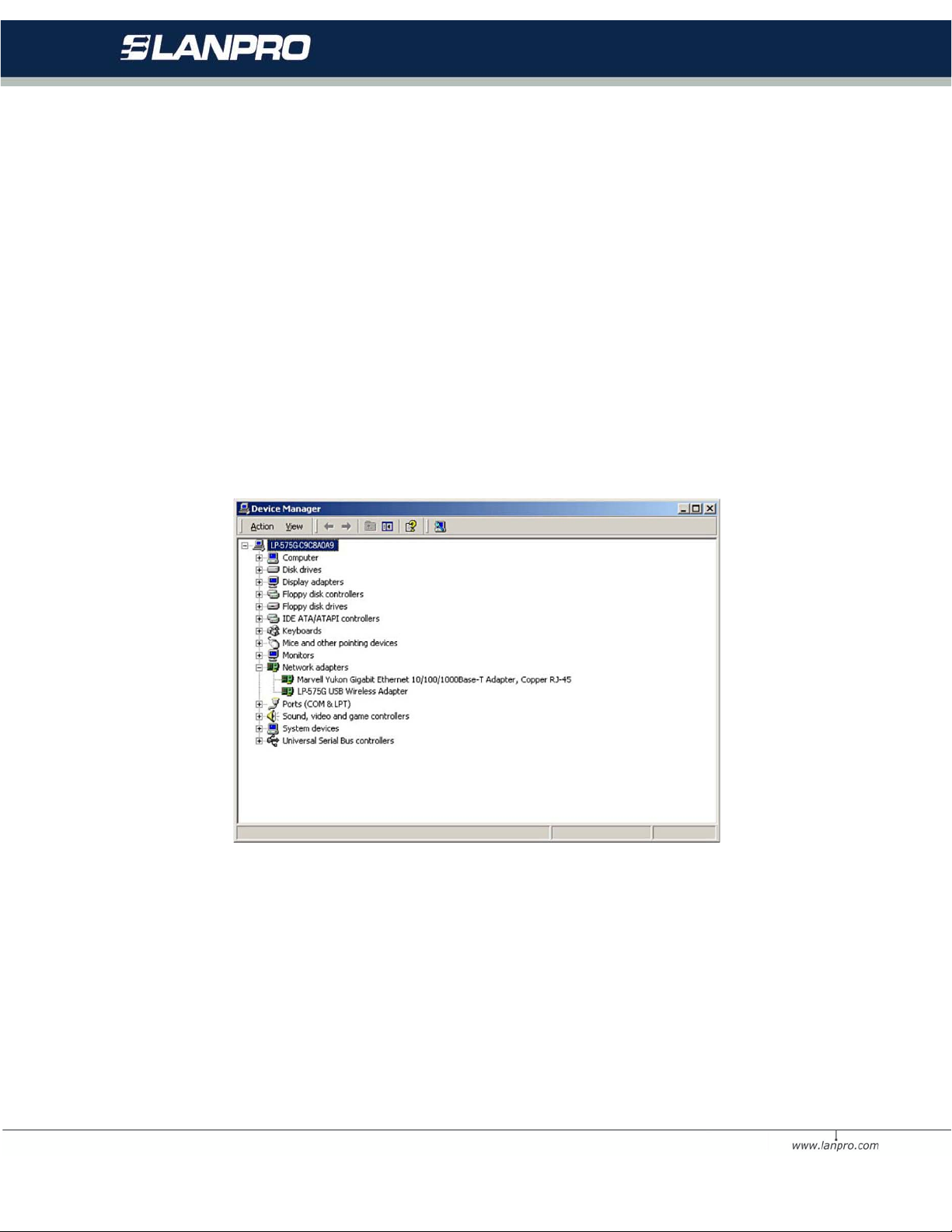
1. On the Windows taskbar, click the Start button, point to Settings, and t hen
click Control Panel.
2. Dou ble-click the System icon, click on the Hardware tab in the System
window.
Click on the Device Manager button, double-click Network Adapte rs, and
then right-click LP-575G USB
Wireless Adapter.
Figur e 2-6 Uninstall Driver
3. Click Uninstall..., shown in above figure 2-6, the system will uninstall
the driver software of the adapter from your PC.
12
Page 13
Uninstall the utility software from your PC
1. On the Windows taskbar, click the Start button, point to Settings, and then
click Control Panel
2. Dou ble -click the Add/Remove Program s icon, find the LP-575G program
from the installed program list,
highlight it and click the Remove button.
3. Following the Install Shield Wizard will uninstall the utility software from
your PC.
Chapter 3: Configuration
The LP-575G USB Wireless Adapter can be configured by its utility. This section
descri bes how to confi gure your USB Wirel ess Adapt er for wireles s con nectivity
on your Wireless Local Area Network (WLAN) and use the data security
encr yp t io n fe atures.
After the Adapter's driver and utility has been installed, the adapter’s tray icon
, or, will appear in your system tray. It means the uti lity is running on
your system. If the utility does not run, you can run the utility by clicking:
Start> Program> LanPro > LP-575G WIRELESS UTILITY> LP-575G
Wireless Utility. If th e i con still does not appear, the driver or utility may be
inst a lled i nc or re c tly or the ad ap ter is unplugged, please try again.
Icon means the connection has been established. Icon means there i s
no connection.
Double-click the icon and the configuration screen of the utility will appear.
You can also run the utility by clicking: Start> Program> LanPro > LP-575G
13
Page 14

WIRELESS UTILITY> LP-575G Wireless Utility. The utility provides a
complete and easy to use set of tools to:
• Display current status information
• Edit and add configured profiles
• Display current diagnostics information
The section below introduces these above capabilities.
Note: If your OS is Windows XP, you can use Windows XP to configure the
wireless network settings. (To use this function, you must upgrade the OS with
sp1).
If you want to use Windows XP to configure wireless network settings, just exit
the utility. Right-click the icon at the bottom of the screen, and click Exit
to exit the utility.
3.1 Profile
Click the Profile tab of the utility and the Profile screen will appear, figure
3-1. The Profile screen provides tolos to:
• Add a Profile
• Delete a profile
• Edit a profile
• Act iv at e a prof ile
14
Page 15
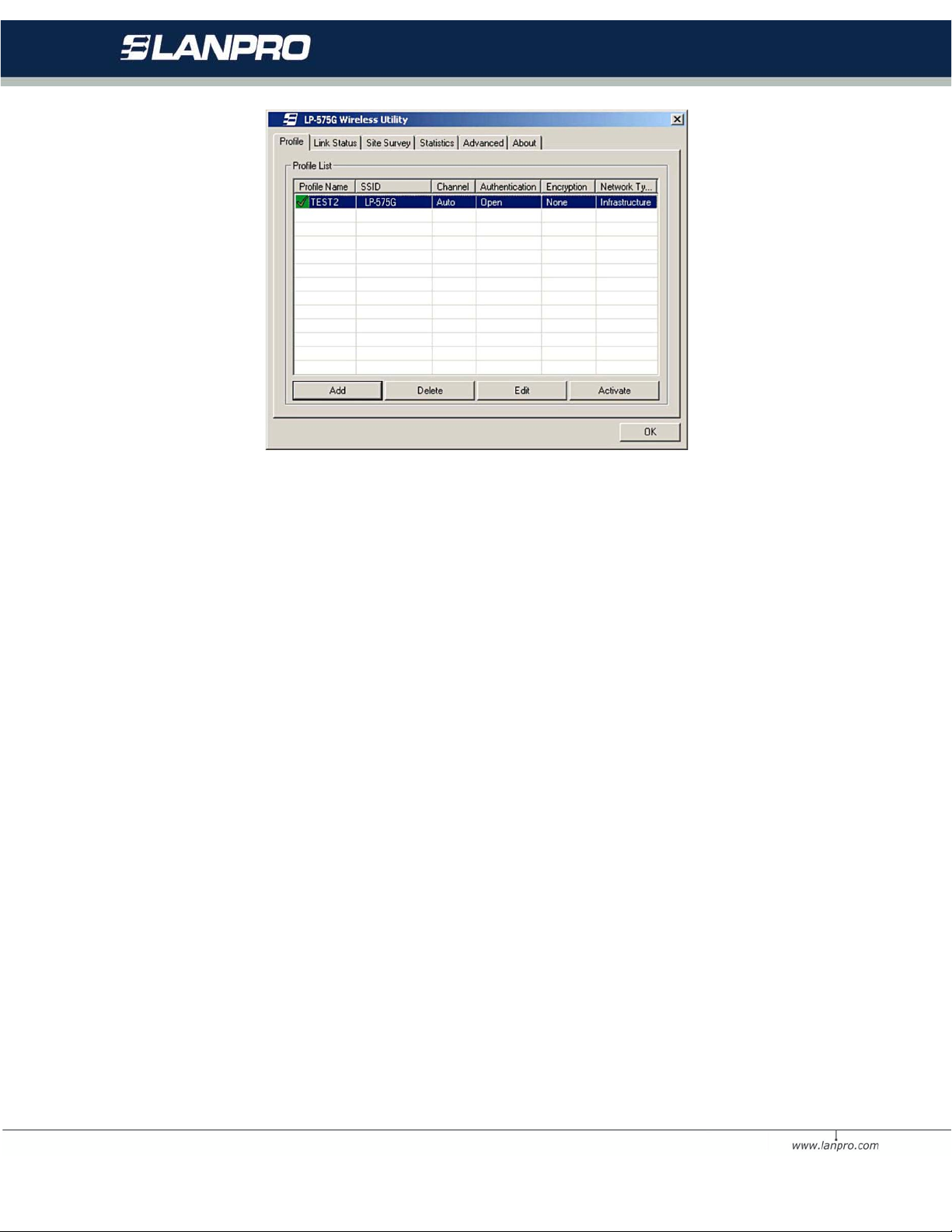
Figur e 3-1 Profile Tab
To create a new profile, click the Add button on th e Profile tab, the Profile
conf ig ur atio n scre en wil l app e ar as
show n in fig ur e 3-2.
To edit a profile, highlight the desired profile name on Profile Name list,
and click the Edit button, the Profile configuration screen will appear shown in
figure 3 -1.
To de le te a pro file , hi ghlight the desired pr ofile nam e on Profil e Name list,
and click the Delete button.
To switch to another profile, highligh t the desired pro file name on Profile
Name list, and click the Activate button.
Note: Do n ot forget to click the Apply button when you create a new profile
for connection.
15
Page 16

3.1.1 Add or Edit a Configuratio n Profile
To add a new configuration profile, click Add button on the Profile Management
tab. To modify a configuration profile, select the configuration from the Profile
list and click Edit
The Profile Management dialog box will display a screen similar to that shown
in Fig ur e 3-2.
1. Edit the Configuration tab
• Profile Name - Identifies the configuration pr ofile. This name must be
unique. Profile names are not
• case-sensitive.
• SSID - The IEEE 802.11 wireless network name. This field has a
maximum limit of 32 characters.
• PSW(Powe r S av e Mode)
• CAM(Const ant ly Awake Mode) - Continuous Access Mode.
• PSW(Power Saving Mode) - Power Saving mod e.
• Network Type - Displays the wireless mode, either Ad-hoc or
Infrastructure mo d e
• Preamble - Specifies the preamble setting in 802.11b. Th e
default set ting is Aut o S w it ch (ac cess poin t
• mode), which allows both short and long headers in the 802.11b
frames. The adapte r can only use short
• radio headers if the acce ss point suppo rts and uses them.
• RTS Threshold - Default is 2312.
• Fragment Threshold - Default is 2312.
• Ad-hoc mode - Displays the wireless mode, either Only 802.11B
or 802.11B/G mo de.
16
Page 17
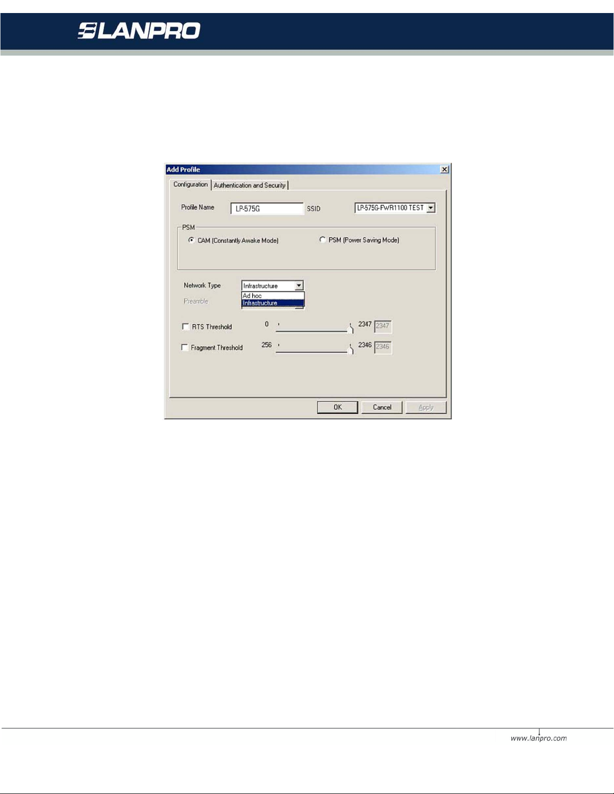
• Channel - Shows the current channel in use. This field determines
which operating frequency will be
• used.
Figur e 3-2 A dd Pr o file – configuration
2. Edit the Authentication and Security tab
17
Page 18
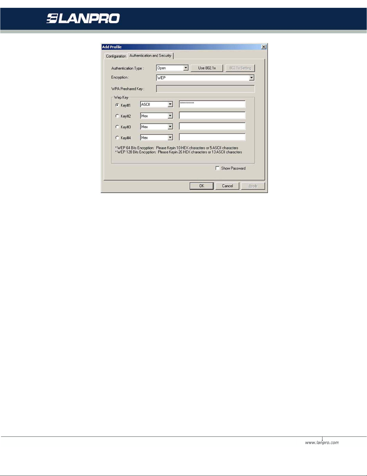
Figur e 3-3 A dd Pr o file – configuration
• Authentication Type - Three options, Open System, Shared-Key
System or LEAP.
• 802.1x Setting - It enables when Authentication Type is setting to
WPA.
• Encryption - Displays which encryption type that the driver is using.
Whe n yo u se le ct Open System,
• Shared-Key System as Network Authentication, there are two
options: WEP and Disabled. If you select
• WPA-PSK as Network Authentication, there are TKIP and AES
optio ns i nst e ad of WEP and Disabled.
• Wep Ke y - Key #1 , Key #2, Key #3, Key #4, the Key groups. You can
enter 10 hexadecimal digits (any combination of 0-9, a-f, A-F) or 5
ASCII characters for 64-bit (also called 40bits) encryption. You can enter
26 hexadecimal digits (any combination of 0-9, a-f, A-F) or 13 ASCII
characters for 128-bit (also called 104bits) encryption.
18
Page 19
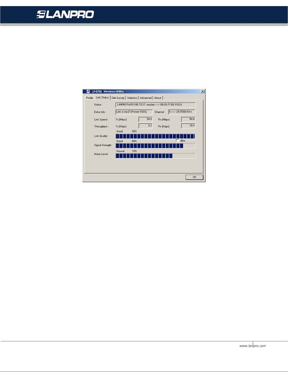
3.2 Link Status
The Link Status tab displays the adapter's current status.
Figure 3-4 Link Status
The following table describes the items found on the Network Status screen.
• Status - Shows whether the station is connected to the wireless
netw or k , if no t c o nne c te d , d isp l ay RF is c losed; if connected, display AP
name and BSSID.
• Extra Info - Show s l ink stat us a nd the c urr ent cha n ne l in use.
• Link Speed - Shows the current max Transfer rate, unit is Mbit/sec.
• Throughput - Displays Tx and Rx rate, unit is Kbits/sec.
• Link Quality - Shows the quality of the signal.
• Signal Strength - Shows the strength of the signal.
19
Page 20
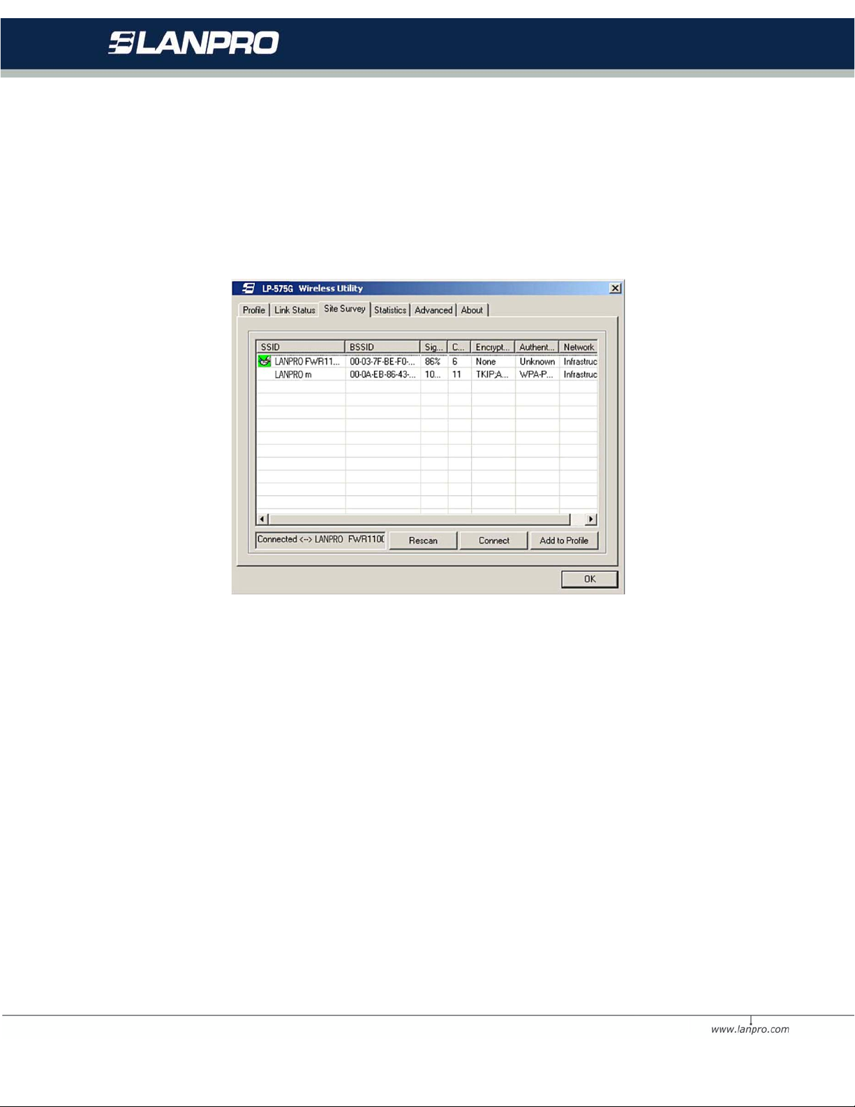
3.3 Site Survey
Click the Site Survey tab of the Utility and the Site Survey screen will
appear, figure 3-5. On the Site Survey screen you can scan the Available
Infrastructure and Ad Hoc Networks.
Figure 3-5 Site Survey tab
Haga clic en Rescan para refrescar la lista en cualq uier m omento. Resal te un
SSID y hag a c l ic e n Connect para conectarse a una red disponible.
3.4 Statistics
The Statistics tab shows receiving and transmitting statistical information for
the following receive and transmit diagnostics for frames received by or
transmitted to the wireless network adapter. Click the Reset Counter button
to reset the count of the statistics information.
20
Page 21
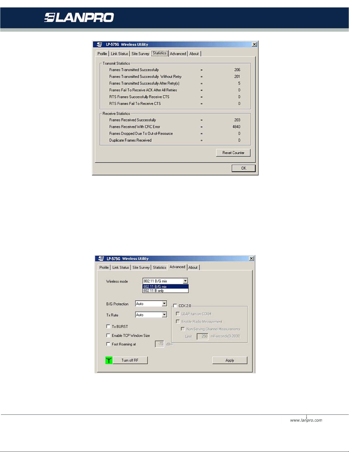
Figur e 3-6 Statistics tab
3.5 Advanced
On this Screen, you can configure the WEP key or view the configured WEP
key.
Figur e 3-7 A dva nced
21
Page 22

Wireless mode - Displays the wireless mode, either 802.11B/G mix or
802.11B only.
B/S Protection - There are three options: either Auto or Enable, o r Close.
TxRate - Shows the current Transfer rate.
TxBURST - It can translate more data when it enable.
Fast Roaming at - Roaming will disable when Transmit Power is below some
dBm.
Turn off RF - The wireless radio of this adapter can be enabled or disabled.
You can turn the wireless radio
off b y selecting the check-box.
Apply - Cli ck the Apply button to save the current setting.
3.6 About
This screen displays some informati on about this adapter, including Driver
Date, Driver Version, Utility Date, Utility Version, MAC Address, IP Address,
SubMask, Power Save mode and Preamble.
• Utility Version - The version of this utility.
• Utility Date - The creation date of this utility.
• Driver Version - Th e v ersion of the wireless network adapter driver.
• Driver Date - The creation date of the wireless network adapter driver.
• EEPROM Version - The version of this EEPROM.
• IP Address - The IP addr ess of the wireless network.
• Phy_Address - The MAC address of the wireless network adapter.
• SubMask - The subnet mask of the wireless network.
• Default Gatew ay - The default gateway of the wireless network.
22
Page 23
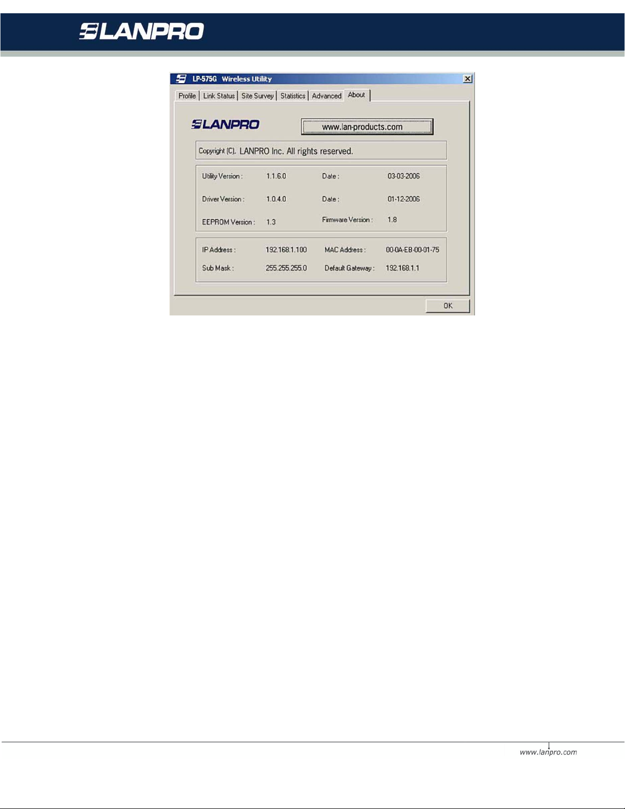
Figur e 3-8 A bout
3.7 An example f o r applicat ion
Suppose you have an installed and using AP, the SSID is LanPro and it adopts
64-bit encryption with the key 0123456789. To establish a connection wi th this
AP, you should follow these steps below:
1. Launch LP-575 G Wir eless Uti lit y .
2. Click the Profile tab of the utility and click the New button on the
screen that appears.
3. The Profile configuration screen will appear, please enter Test for the
Profile Name, LanPro for the SSID, select
4. Infrastructure for the N etwo rk Mode, sel ec t WEP for the Data Encryption
and enter 0123456789 for N etwork key.
5. Click OK to save thi s profile.
23
Page 24
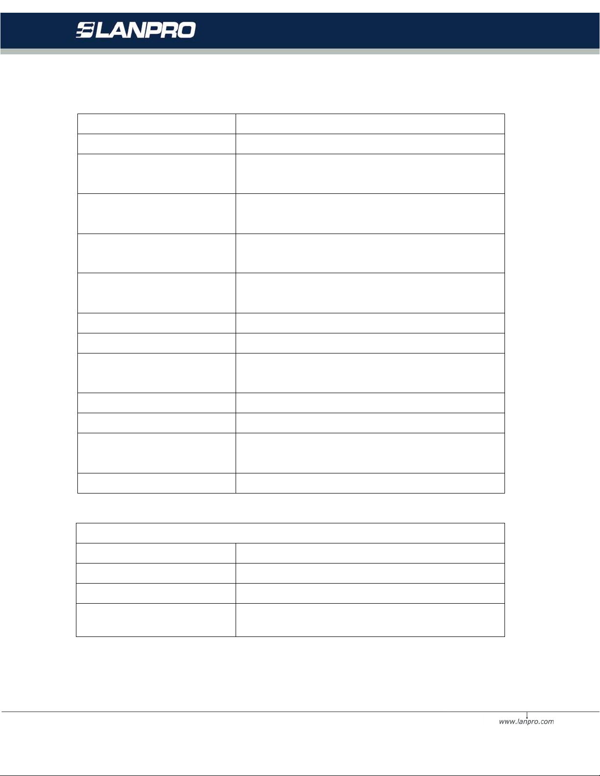
Interface
A-type USB 2.0 Connector
Windows 98SE, Me, 2000, XP, Vista and Linux,
In door up to 100m, out door up to 300m
1M DBPSK ; 2M DQ PSK ; 5. 5M , 1 1M CCK; 6M,
Media Access Protocol
CSMA/CA with ACK
WPA; 64/128 BIT WEP; TKIP /AES; IEEE802.1x
Spread Spectrum
Direct Sequence Spread Spectrum (DSSS)
Physical Environmental
Operating Temp
0ºC ~40ºC (32º~104º)
Humidity
10% - 95% RH, Non-condensing
Appendix A: Specifications
Standards IEEE802.11b; IEEE802.11g
Operating System
Macintosh
Transmission Distance
(it is lim it e d to the environment).
54/48/36/24/18/12/9/6 Mbps
Radio Data Rate
or 11/5.5/3/2/1Mbps (Auto Rate Sensi ng)
Modulation
Transmit Power 22dBm (Typical)
Data Security
Frequency 2.4 ~ 2.4835 GHz
Power Consumption
Safety & Emissions FCC, CE
Storage Temp -40ºC - 70ºC (-40ºC ~ 158ºC)
9M, 12M, 18M, 24M , 36M , 48 M, 54M OFDM;
authentication
Typically 480mA in full Transmit (TX), 420mA
in full Receive (RX)
Dimensions
(W×D×H)
3.4×1.0×0.5 in. (86×26×12 mm)
24
Page 25

Appendix B: Glossary
• 802.11b - The 802.11b standard specifies a wireless networking at 11
Mbps using direct-sequence spread-spectrum (DSSS) technology and
operating in the unlicensed radio spectrum at 2.4GHz, and WEP
encryption for secu rity. 802.11b networks a re also referred to as Wi-Fi
networks.
• 802.11g - specification for wireless networking at 54 Mbps using direct-
sequen ce spread-spectrum (DSSS) technology, using OFDM modulati on
and operating in the unlicensed radio spectrum at 2.4GHz, and
backward compatibility with IEEE 802.11b devices, and WEP en cryption
for security.
• Ad-hoc Network - An ad-hoc network is a group of computers, each
with a wireless adapter, connected as an independent 802.11 wireless
LAN. Ad-hoc wireless computers operate on a peer-to-peer basis,
communicating directly with each other without the use of an access
point . Ad-hoc mo de is al so ref erred to a s an In dependent Ba sic Servi ce
Set (IBSS) or as peer-to-peer mode, and is useful at a departmental
scale o r SO HO o pe r ation.
• DSSS (Direct-Sequence Spread Spectrum) - DSSS generates a
redundant bit pattern for all data transmitted. This bit pattern is called
a chip (or chipping code). Even if one or more bits in the chip are
damaged during transmission, statistical techniques embedded in the
receiver can recover the original data without the need for
retransmission. To an unintended receiver, DSSS appears as low power
wideband noise and is rejected (ignored) by most narrowband receivers.
However, to an intended receiver (i.e. another wireless LAN endpoint),
the DSSS signal is recognized as the only valid signal, and interference
is inherently rejected (ignored).
• FHSS (Frequency Hopping Spread Spectrum) - FHSS continuously
changes (hops) the carrier frequency of a conventional carrier several
times per second according to a pseudo-random set of channels.
25
Page 26

Because a fixed frequency is not used, and only the transmitter and
receiver know the hop patterns, interception of FHSS is extremely
difficult.
• Infrastructure Network - An infrastructure network is a group of
computers or other dev ices, ea ch with a wireless adapter, connected as
an 802.11 wireless LAN. In infrastructure mode, the wireless devices
communicate with each other and to a wired network by first going
through an access point. An infrastructure wireless network connected t o
a wired netwo rk is ref erred to as a Basic Service S et (BSS). A set of two
or more BS S in a si ngle networ k is referred to as an Exten ded Service
Set (ESS). Infrastructure mode is useful at a corporation scale, or when
it is necessary to connect the wired and wireless networks.
• Spread Spectrum - Spread Spectrum technology is a wideband radio
frequency technique developed by the militar y for use in reliable, secure,
mission-critical communications systems. It is designed to trade off
bandwidth efficiency for reliability, integrity, and security. In other
words, more bandwidth is consumed than in the case of narrowband
transmission, but the trade off produces a signal that is, in effect, louder
and thus easier to detect, provided that the receiver knows the
parameters of the spread-spectrum signal being broadcast. If a receiver
is not tuned to the right frequency, a spread-spectrum signal looks like
background noise. There are two main alternatives, Direct Sequence
Spread Spectrum (DSSS) and Frequency Hopping Spread Spectrum
(FHSS).
• SSID - A Service Set Identification is a thirty-two character (maximum)
alphanumeric key identifying a wireless local area network. For the
wireless devices in a network to communicate with each other, all
devices must be configured with the same SSID. This is typically the
configuration parameter for a wireless PC card. It corresponds to the
ESSID in the wireless Access Point and to the wireles s network name.
26
Page 27

• WEP (Wired Equivalent Privacy) - A data pri vacy mecha nism based on
a 64 -bit o r 128-bit o r 152-bit shared key algorithm, as described in the
IEEE 8 02. 11 s ta nd ard .
• Wi-Fi - A trade name for the 802.11b wireless networking standard,
given by the Wireless Ethernet Compatibility Alliance (WECA, see
http://www.wi-fi.net), an industry standards group promoting
interoperability among 802.11b devices.
• WLAN (Wireless Local Area Network) - A group of computers and
associated devices communicate with each other wirelessly, which
netw or k ser vi ng us e rs ar e lim it ed in a lo c a l ar ea.
• WPA (Wi-Fi Protected Access) - A wireless security protocol use TKIP
(Temporal Key Integrity Protocol) encryption, which can be used in
conjunction with a RADIUS s erver.
Append ix C: Contac t Inform a tion
For help with the installation or operation of the LP-575G please contact us.
To know more about our products , please visit www.lanpro.com or email us
directly to www.lanpro.com
27
 Loading...