

Page 1

LP-1518
LP1518_UM_ENB01W
Wireless Access Poin t
User’s Manual
Page 2

Contents
1 Introduction ......................................................................................................................................................... 3
1.1 Features and Benefits .................................................................................................................................. 3
1.2 Applications ................................................................................................................................................. 3
2 Before You Start ............................................................................................................................................... 4
2.1 You must have the following items .............................................................................................................. 4
2.2 Checklist ...................................................................................................................................................... 4
3 Hardware Installation .......................................................................................................................................... 5
3.1 Connect the station adapter to your Ethernet-enabled device ....................................................................... 5
3.2 Mechanical Description .................................................................................................................................. 5
3.3 System configuration ...................................................................................................................................... 6
3.3.1 Install an AP ......................................................................................................................................... 6
3.3.2 Install a Station---Connecting One Ethernet-Device (as Station) .......................................................... 7
3.3.3 Install a Station---Connecting Multiple Ethernet-Devices (as Bridge) ................................................... 7
3.3.4 Install a WDS ........................................................................................................................................ 8
4 Configure Your 3-in-1 AP.................................................................................................................................... 9
4.1 Using the 3-in-1 AP Web Management .......................................................................................................... 9
4.1.1 How to access the web-bro wser configuration utility? .......................................................................... 9
4.1.2 Information ......................................................................................................................................... 10
4.1.3 Configuration ...................................................................................................................................... 11
4.1.4 TCP/IP ................................................................................................................................................ 19
4.1.5 Firmware Upgrade .............................................................................................................................. 20
4.2 Using the 3-in-1 AP Utility .......................................................................................................................... 21
4.2.1 Configuration ...................................................................................................................................... 22
4.2.2 TCP/IP ................................................................................................................................................ 26
4.2.3 Advance ............................................................................................................................................. 26
5 Wireless Connection to the Internet /Head-to-Head for your Gaming Console ........................................... 28
5.1 Internet Gaming ......................................................................................................................................... 28
5.2 Head To Head Gaming .............................................................................................................................. 28
6 Troubleshooting ................................................................................................................................................ 30
Appendix A Limited Warranty ............................................................................................................................. 33
2
Page 3

1 Introduction
This W ireless 3-in-1 AP is quite a friendly device to have around, with dedicated one LAN/W AN port, it can be
communicated with other mobile devices for 802.11g standard-base wireless network connecti vity. Let you quickly
network multiple PCs and notebooks without laying cables, and gives users the freedom to roam throughout the
workplace and stay connected to corporate resources, e-mail and Internet access.
1.1 Feature s and Be nef its
• High Speed & Backward Compatible
The high-speed wireless device simultaneously supports both IEEE802.11b/802.11g 54 Mbps wireless
networks.
• 3-in-1 AP operating mode
Three different functions are integrated as well: Access Point, Station, WDS.
• Multiple Client Support
Create a large wireless network to connect more hubs or switches.
• WEB Interface
It is easy to configure the device or upgrade the Firmware via WEB browser.
• Enhanced Security
Provides the highest av ailable level of WEP /WAP-PSK as well as MAC Address Control to increase security.
1.2 Applications
The Wireless 3-in-1 AP offers a fast, reliable, high-speed, and high security solution for wireless cli ents access to
the network in applications like these:
1. Remote access to corporate network information E-mail, file transfer and terminal emulation.
2. Difficult-to-wire environments. Historical or old buildings, asbestos installations, and open area where
wiring is difficult to deploy.
3. Frequently changing environments
Retailers, manufacturers and those who frequently rearrange the workplace and change location.
4. Temporary LANs for special projects or peak time
• Trade shows, exhibitions and construction sites where a temporary network will be practical.
• Retailers, airline and shipping companies need additional workstations during peak period.
• Auditors requiring workgroups at customer sites.
5. Access to database for mobile workers Doctors, nurses, retailers, accessing their database while being
mobile in the hospital, retail store or office campus.
6. SOHO (Small Office and Home Office) users SOHO users need easy and quick installation of a small
computer network.
7. High security connection
The secure wireless network can be installed quickly and provide flexibility.
3
Page 4

Character
2 Befo re You Start
2.1 You must have the following items
An Ethernet-enabled device, such as a game console, PC, or network printer will connect to the 3-in-1 AP.
2.2 Checklist
If you discover damaged or missing items, please contact your local reseller.
• 802.11g Wireless LAN 3-in-1 AP x 1
• Power Adapter x 1
• CD x 1
Ethernet Connector: 10/100BaseTR-45 LAN port with Auto-MDIX
Power Supply: DC 5V/2A
Configuration: Smart Utility/ WEB Management
Antenna: One External di pole antenna, gain 2dBi, with diversity function
Operation: Access Point / Station Adapter / WDS
Supported Operating Systems: Win98SE/ME/2000/XP
Security:WEP/WPA-PSK
4
Page 5

3 Hardware Installation
3.1 Connect the station adapter to your Ethernet-enabl ed dev ic e
1. Combine the antenna with the 3-in-1 AP to wirelessly connect to the 802.11g networks.
2. Connect one end of an Ethernet cable to the 3-in-1 AP and connect the other end to the Ethernet LAN
port located on the device (e.g., a gaming console, laptop, desktop computer, or netw ork printer).
3. Connect the power adapter to the 3-in-1 AP
3.2 Mechanical Description
The following table provides an overview of each LED activity:
5
Page 6

Power Socket
Using the power adapter supplied with the 3-in-1 APwill prevent damage to the station adapter and personal injury.
Note:
We cannot ass ume the responsibility for the damage from using w ith the other power adapter supplier.
LAN Ports
Connect the 3-in-1 AP to a hub or a PC with Ethernet cable. Please note that, use the Ethernet cable when you
directly connect 3-in-1 AP to a PC.
Antenna
Notice that you connect tightly the External dipole antenna on the antenna connector of your 3-in-1 AP. A loosen
antenna will reduce the radiant energy or even lose it. In order to improve the RF signal radiation of your antenna,
proper antenna placement is necess ary. Try to place the antenna as high as possible to increase the coverage
area. If you have further question, please contact your wireless network administrator.
Default
Press the Default button for about 3 seconds until all LEDs go off. This action will restore to the factory default
settings of the 3-in-1 AP. Besides, this is also used when you forget the password.
3.3 System configuration
The 3-in-1 AP can be configured in a variety of network system configurations s uch as AP mode, Station mode or
WDS mode.
3.3.1 Instal l an AP
The 3-in-1 AP can be configured to work as a wireless network access point. Please take the following steps to
successfully set up the Access Point.
1. Attach one end of the Ethernet Cable to the Access Point and connect the other end of the Ethernet cable
to a hub or a station (PC).
2. Connect the power adapter to the power socket on the AP. The power and the Ethernet status
should light up.
3. When the station adapter is associated to the Wireless AP and Wireless LAN traffic activity, you will see
the wireless LAN status lights up.
4. Place your 3-in-Access Point at your site in the center of your wireless coverage area.
6
Page 7

3.3.2 Install a Station---Connecti ng One Ethernet-Device (as Station)
The 3-in-1 AP can be configured to work as a client mode. To connect with one client, follow these steps:
1. Connect one end of the Ethernet Cable to the Station Adapter and the other to the Ethernet –enabled
device.
2. Connect the power adapter to station adapter’s power jack. The power and the Ethernet status
should light up.
3. Turn on the Ethernet-enabled device. When the station adapter is associated to the Wireless AP and
Wireless LAN traffic activity, you will see the wireless AN status lights up.
3.3.3 Install a Station---Connecting Multiple Ethernet-Devices (as Bridge)
The station can be implemented on allowing multi-clients to join a network. To connect with multi-clients, follow
these steps:
1. Connect one end of the Ethernet Cable to the Station Adapter and the other to the hub.
2. Connect the Ethernet Cable between Ethernet-enable devices and the hub.
3. Connect the power adapter to station adapter’s power jack. The power and the Ethernet light should light
up.
4. Connect the power adapter to the hub.
5. Turn on all Ethernet -enable devices. When the station is associated to the
6. Wireless AP and Wireless LAN traffic activity, you will see the wi reless LAN status lights up.
7
Page 8

Note:
A hub could connect with up to 8 Ethernet-devices. However, it would reduce the transmission rate if
connected with too many units. (The more units to connect with will produce less tran smission rate.)
Note:
If all of your cl ients do not support TCP/IP protocol, only the first client can connect to the wireless station
adapter.
3.3.4 Install a WDS
The 3-in-1 AP can be configured as a WDS. Under this mode, you can extend the range of your network by adding
additional 3-in-1 AP with WDS mode for each additional LAN Segment. To connect two or more than two APs with
WDS mode please do the following:
1. Attach one end of the Ethernet Cable to AP1 and connect the other end of the Ethernet Cable to Client1.
2. Attach one end of the Ethernet Cable to AP2 and connect the other end of the Ethernet Cable to Client2.
3. Connect the power adapter to the power socket on both of AP1 and AP2. The power and the
Ethernet light should light up.
4. When AP1 and AP2 are associated with each other and Wireless LAN traffic activity, you w ill see the
wireless LAN status lights up.
8
Page 9

4 Configure Your 3-in-1 AP
The Wireless 3-in-1 AP is shipped with default parameters, which will be suitable for the typical
infrastructure/ad-hoc wireless LA N. Just s imply ins tall the 3-in-1 AP, power it on, and it i s now ready to work.
Nevertheless, you can still switch the configuration settings depending on how you would li ke to manage your
wireless network. You are allowed to configure the 3-in-1 AP with a web browser (Web Management), or the smart
configuration utility, known as an Access Point Manager.
4.1 Using the 3-in-1 AP Web Manage me nt
The built-in Web Management provides you wi th a user-friendly graphical user interface (web pages) to m anage
your 3-in-1 AP.
4.1.1 How to access the web-browser configuration utility?
1. Connect your computer to the wireless adapter either through wireless or wired connection. Please set a
fixed IP address (refer to Chapte r 6), within the range of 192.168.0.X (X
can’t be 2), to your computer.
2. Activate your browser, then type this 3-in-1 AP’s address (e.g. http://192.168.0.2), in the Location (for IE)
or Address field and press Enter.
3. Key in the system password (the default setting is default) and click on the Login button. You will see the
main page.
9
Page 10

The main window provides 5 items for you to monitor and configure the Wireless 3-in-1 AP : Information, Configuration,
TCP/IP, Statistics and Fi rmware Upgrade.
4.1.2 Infor m atio n
This item shows the current information on th e 802.11g Wirel ess 3-in-1 AP su ch a s MAC Add ress, Firmware Version as
well as Boot Version.
10
Page 11

4.1.3 Configuration
4.1.3.2 Gener al Pa ge
Access Point Name: In this field, you may enter any name. This will enable you to manage your 3-in-1 AP more
easily if you have multiple 3-in-1 APs on the network. Besides, Access Point Name can be used to prevent you
from forgetting an IP Address and fail to access the w ebsite. Try to type the nickname you like to identify the
website, then press the button of Apply. Whenever you want to get back to the website again,
just type the name you login.
Wireless Mode: The default wireless operating mode of the 3-in-1 AP is Access Point (AP) mode. To switch to AP
or Station mode, select the desired mode from the down-arrow menu. Click Apply. The board will reboot into the
desired mode.
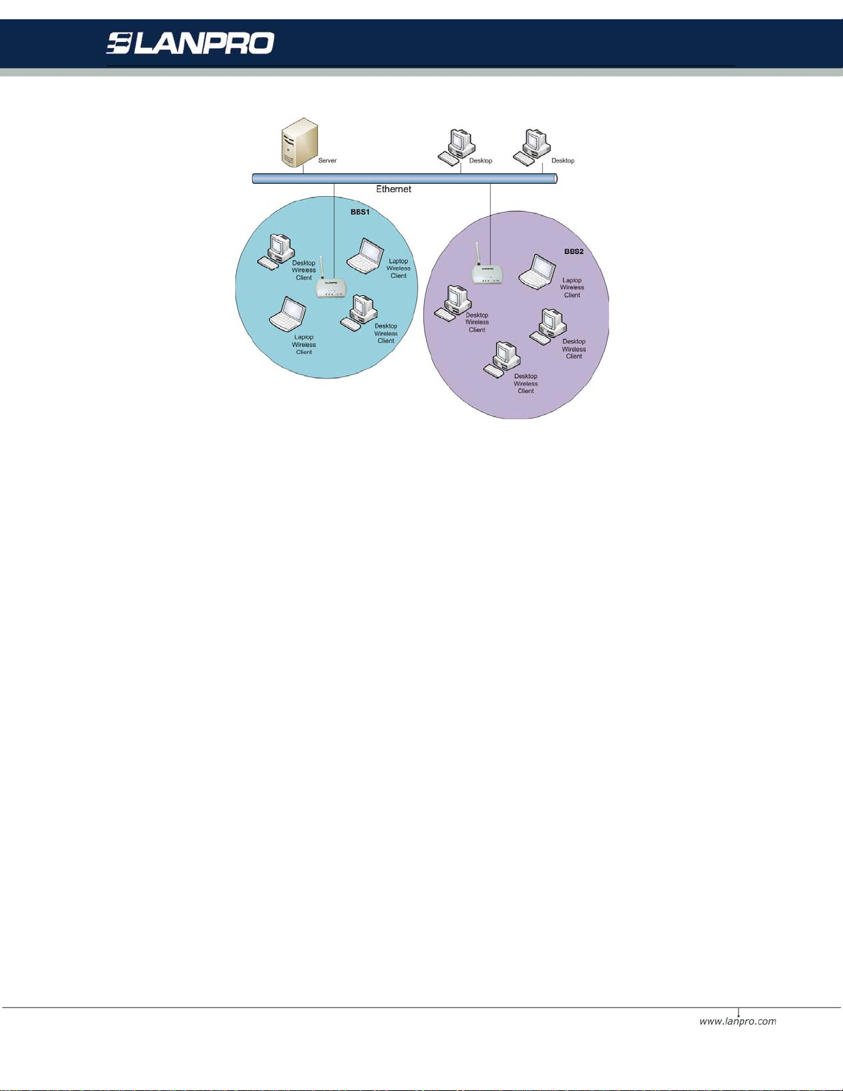
• AP Mode: The system can be configured to work as a wireless network access point. Note that the
3-in-1AP acts only as a layer 2 bridge and does not act as a DHCP server. In other words, it does not
supply dynamic IP addresses and instead relies on the network to supply them . The implementation can
be shown as below:
11
Page 12
• Station Mode: When configuring as a station mode, the devi ce is now acting as a wireless client. The
3-in-1 AP will associate to an AP within its range in infrastructure mode, or join with another 3-in-1 device
in Client mode in an ad-hoc network. The implementation can be shown as below: Infrastructure Ad-Hoc.
Network T ype: There are 2 network types for the wireless station adapter to operate. If you need to access
company network or Int ernet v ia Access Point, select Infrastructure. To set up a group of wireless stations for files
and printer sharing, select Ad-Hoc (without Access Point). For Ad-Hoc operation, the same ESSID is
required to set for the wireless stations.
ESSID: The ESSID is a unique ID used by Access Points and Stations to identify a w ireless LAN. Wireless clients
associating to any Access Point must have the same ESSID. The default ESSID is Wireless. The ESSID can have
up to 32 characters.
Channel: Select a clear and available channel as an operational channel for your wireless station adapter when it
performs as Ad-Hoc mode or AP mode.
Mode: There are three different wireless modes to operate, B Only Mode, G Only Mode, and B/G Mixed Mode. In
B/G Mixed Mode, the wireless station adapter is com patible with a mix of both 802.11g and 802.11b clients. You
will see that the factory-set default B/G Mixed Mode will prove the most efficient. B Only Mode is compatible with
802.11b clients only. This mode can be used only if you do not allow any 802.11g clients to join a network. G Only
Mode is compatible with 802.11g clients only. This mode can be used only if you do not allow any 802.11b clients
to access t o the network. To switch the mode, select the desired mode form the pull-do wn menu
next to Mode.
Rate: The wireless station adapter provides various data rate options for you to choose. Data rates options
include Auto, 1, 2, 5.5, 11, 6, 9, 12, 18, 24, 36, 48 and 54. The default setting is Auto.
12
Page 13
Country/Region: Allows you to select country domain in case there is any chances that you would use wireless
network in other countries. There are a total of 11 countries for you to select. They are Africa, Asia, Australia,
Canada, Europe, France, Israel, Japan, Mexico, South America, and USA. Note that if your AP and station adapter
are in different standards, please use the Country/Region item to switch the standards of the station adapter (For
example, when set to client m ode, if your Access Point is America standard but your station adapter is Japanese
standard, you can pull down the Country/Region option to switch your station adapter from Japanese standard to
American standard.). As long as you change the country domain, the channel will switch to correspond with the
country you changed.
Password: You may change the default password by entering the new password.
Click Apply if you have made any changes.
4.1.3.2 Sec urity Page
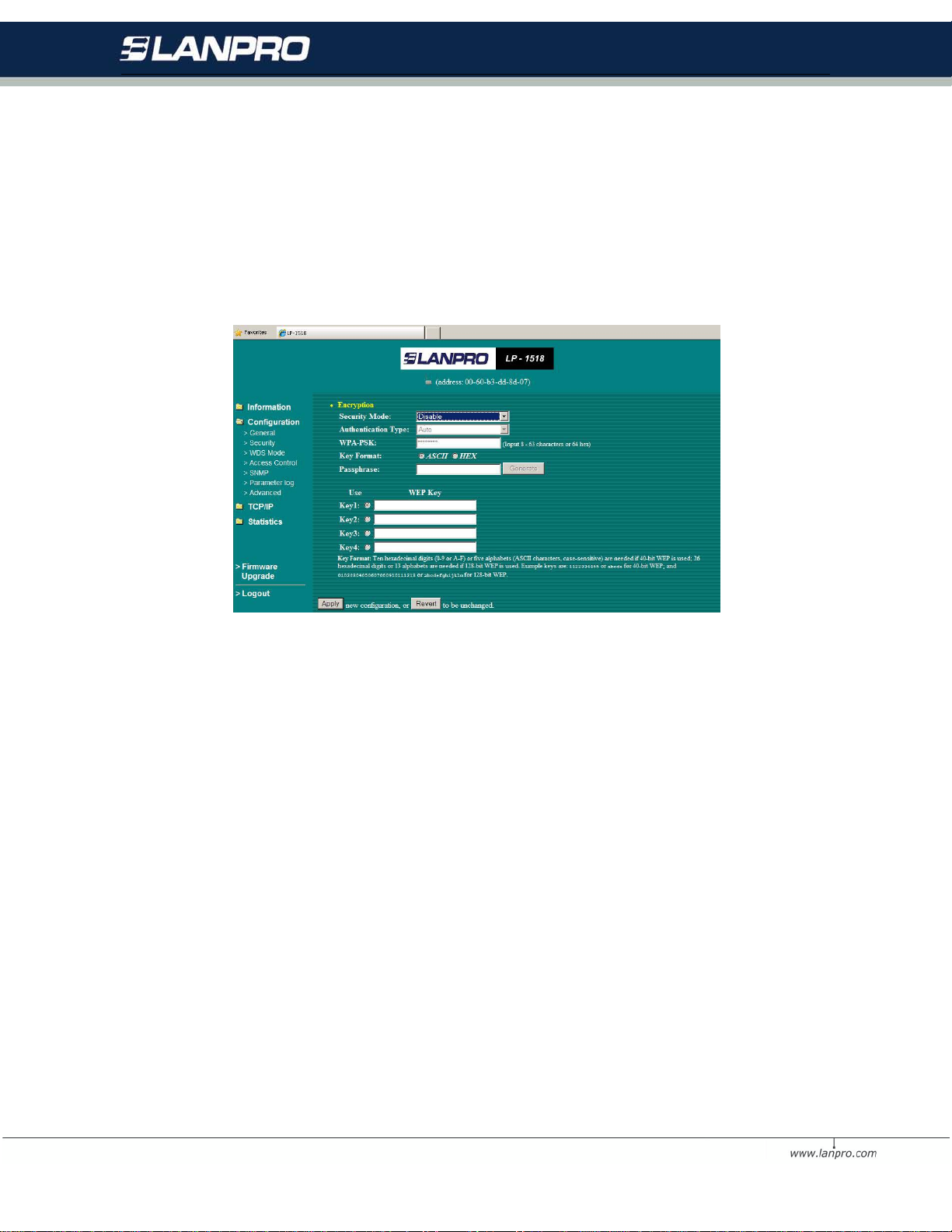
Secur ity Mode: This wire le s s 3-in-1 AP allows you to create up to 4 data encryption keys to secure your data from
being eavesdropping by unauthorized wireless users. To enable the encryption, all devices on the network must
share the same WEP key.
Disable: Allows the wireless station adapter to communicate with the Access Point without any data encryption.
WEP40: Requires the wireless station adapter to use data encryption with 40-bit algorithm when communicating
with the Access Point.
WEP128: Allows the wireless station adapter to communicate with the Access Point with data 128-bit encryption
algorithm.
WPA-PSK: Allows the wireless station adapter to communicate with the Access Point with a more secure data
protection than the WEP. Here you can select the WPA-PSK mode to improve the data security and privacy during
wireless transmission. The present WPA supplied with this 3-in-1 AP is used in a pre-shared key mode, which
does not require an authentication (Radius) server.
13
Page 14
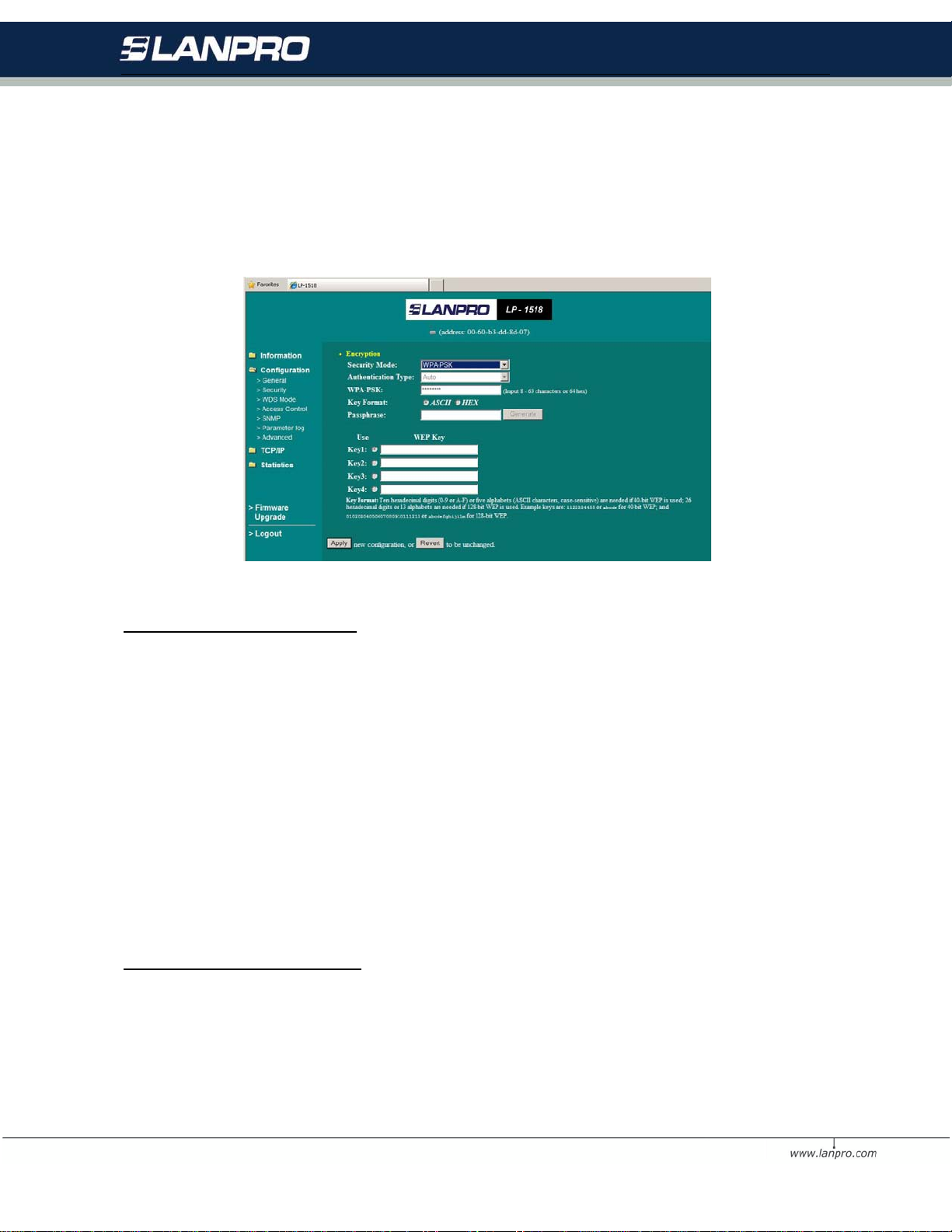
Moreov er, the wireless 3-in-1 AP prov ides three types of authentication services: Auto, Open System and Shared
Key. The default authentication type is Auto. Open S yste m requires no authentication since it allows any device
to join a network without performing any security check. If you require higher security for wireless access, you may
select Shared Key. N ote that when Shared Key is selected, a WEP key is required and must be the same between
the Access Point and client.
For 40bit encryption you may choose:
ASCII: Enter 5 characters (case sensitive) ranging from a-z, A-Z and 0-9 (e.g. MyKey).
Hex: Alternatively, you may enter 10 hexadecimal digits in the range of A -F, a-f and 0-9 (e.g. 11AA22BB33).
For 128bit encryption you may choose:
ASCII: Enter 13 characters (case sensitive) ranging from a-z, A-Z and 0-9 (e.g. MyKey12345678).
Hex: Alternatively, you may enter 26 hexadecimal digits in the range of A-F, a-f and 0-9 (e.g.
00112233445566778899AABBCC)
After entering the WEP keys in the key field, select one key as active key.
Alternatively, you m ay create encryption keys automatically by using Passphrase. From the Passphrase field,
type a character string and click Generate. As you type, the wireless 3-in-1 AP will use an algorithm to generate 4
keys automatically. Select one key from the 4 WEP keys.
For WPA-PSK mode you may choose:
In the WPA-PSK field, you may input 8-63 characters ranging from a-z, A-Z and 0-9 or 64 hexadecimal digits form
A-F, a-f and 0-9. If you require that access to the Internet or other wireless network services are allowed only when
the pre-shared key of the 3-in-1 AP matches that of the device you want to communicate.
14
Page 15
Click the Apply button on the Security tab to make the setting take effect
4.1.3.3 W DS Mode Pa ge
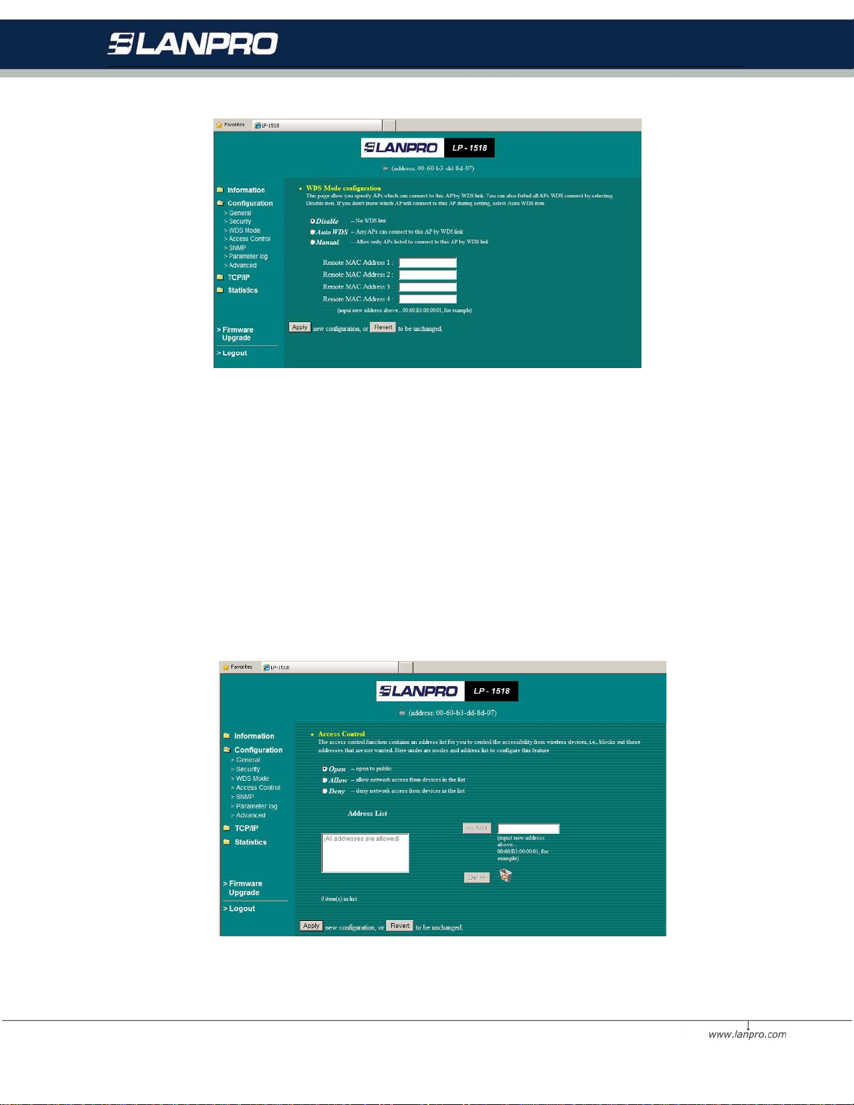
In Wireless Distribution Syste m (WDS) mode, you can ex tend the range of a wireless network. Wireless clients can
associate with the repeater to communicate wi th each c lient on your network. Note that all the Access Points’ IP
address must be set in the same network and make sure that Channel are set the same for all of your AP with
supporting WDS link.
Disable: No WDS link.
Auto WDS: Any Aps can connect to this AP byWDS link.
Manual: Allow only Aps listed to connect to this AP by WDS link.
Click the Apply button on the WDS tab to make the setting take effect
15
Page 16
4.1.3.4 Access Control Page
When configuring the 3-in-1 AP with AP mode operation, the Access Control is a powerful s ecurity feature that
allows you to specify which wireless stations are allowed or denied in the list including:
Open: Allows any wireless station to access the network.
Allow: Any wireless station in this list attempting to access the network is allowed.
Deny: Any wireless station in this list will be denied access.
To add the Mac address of each wi reless station on your network by entering the Mac address of the client you
desire to add into the list. Click Add, and then Apply t o s ave the settings. To delete a Mac address from the list,
select the Mac address you want to delete by clicking Del and then Apply to save the settings
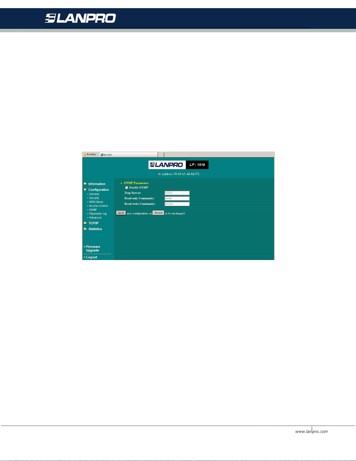
4.1.3.5 SNMP Page
Using the Simple Network Management protocol (SNMP) manage the 3-in-1 AP.
Enable SNMP: To enable the SNMP support feature, select Enable SNMP.
Trap Server: To specify a trap server IP address .
Read-only Community: To assign a name to control the access.
Read-write Community: To assign a name to control the access.
16
Page 17
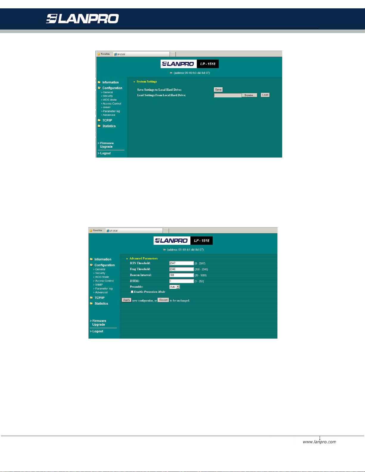
4.1.3. 6 P arameter lo g Pag e
The Parameter log item allows you to save settings to the local hard drive by clicking Save. When you click the
Browse button, you can select the saved setting files. To click Load, the saved settings will be loaded back.
4.1.3. 7 A dvanced Pa ge
RTS Threshold: RTS Threshold is a mechanism implemented to prevent the Hidden Node problem. Hidden
Node is a situation in which two stations are within range of the same Public Access Point, but are not within range
of each other. Therefore, they are hi dden nodes for each other. W hen a hidden station starts data transmission
with the Public Access Point, it might not notice that another station is already using the wireless medium. When
17
Page 18
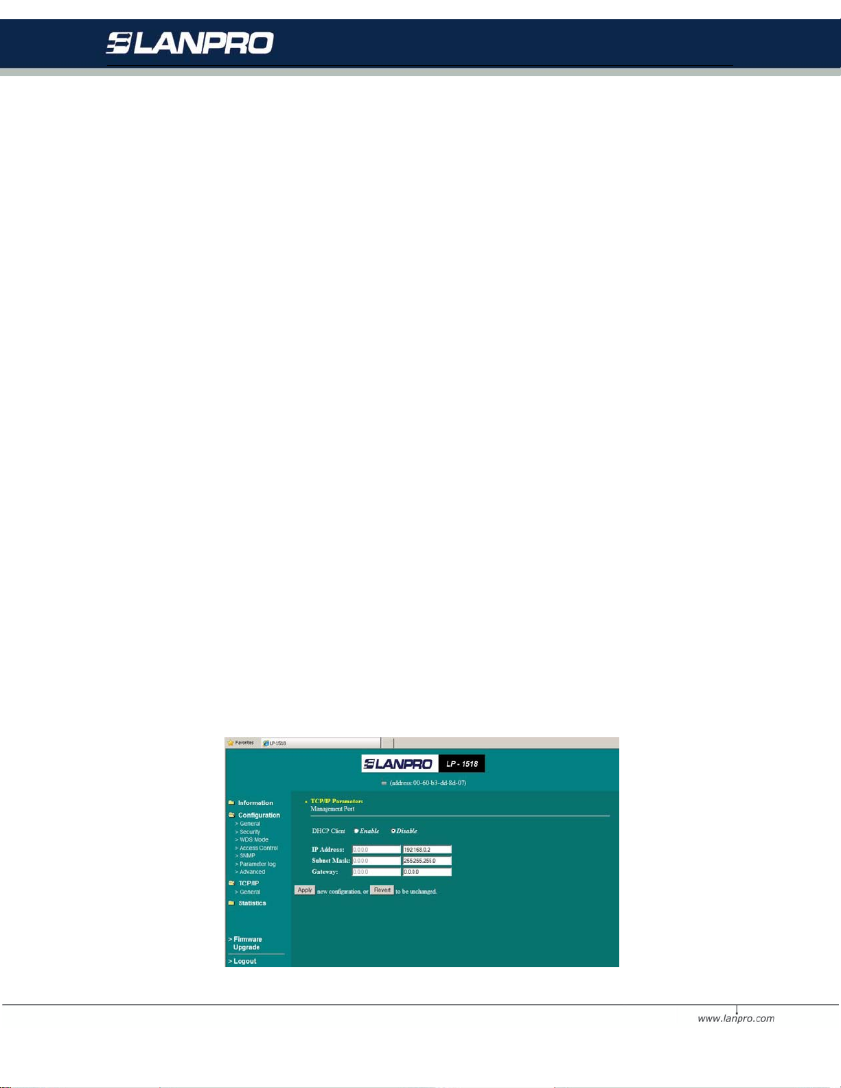
these two stations send data at the same time, they might collide when arriving simultaneously at the Public
Access Point. The collision will most certainly result in a loss of messages for both stations. Thus, the RTS
Threshold mechanism will provide the solution to prevent data collisions. When the RTS is activated, the station
and its Public Access Point will use a Request to Send/Clear to Send protocol (RTS/CTS). The station will send an
RTS to the Public Access Point, informing that it is going to transmit the data. Upon receipt, the Public Access
Point will respond with a CTS message to all station within its range to notify all other stations to defer
transmission. It will also confirm to the requesting station that the Pub li c Access Point has reserved the channel for
transmission.
Fragmentation Threshold: Fragmentation mechanism is used for improving the efficiency when there is high
traffic within the wireless network. If you transmit large files in a wireless network, you can enable the
Fragmentation Threshold and specify the packet size.
Beacon Interval: The amount of time between beacons in kilo m icroseconds.
DTIM: This setting, always a multiple of the beacon period, determ ines how often the beacon contains a delivery
traffic indication message (DTIM). A traffic indication map is present in every beacon. The DTIM notifies
power-save client devices that a packet is waiting for them. If power save clients are active, the access point
buffers any multicast traffics and delivers them immediately after the DTIM beacon. Power save nodes al ways
wake for the DTIM beacons. The longer the time, the more buffering the access point.
Preamble: The radio preamble is a section of data at the head of a packet that contains information the access
point and the client devices need when sending and receiving packets. Keep the setting on short unless you want
to test with long preambles. If you ha ve the radio preamble set to short and a client associates that does not
support short preamble associates, the access point will send only long preamble packets to this client.
• Short - A short preamble improves throughput performance.
• Long - A long preamble ensures compatibility between the access point and all early Wireless LAN
Adapters
• Auto – Including Short and Long preamble.
Enable Protection Mode: Selecting Protection Mode to reduce conflict with 802.11b AP, and also lower
throughput.
18
Page 19
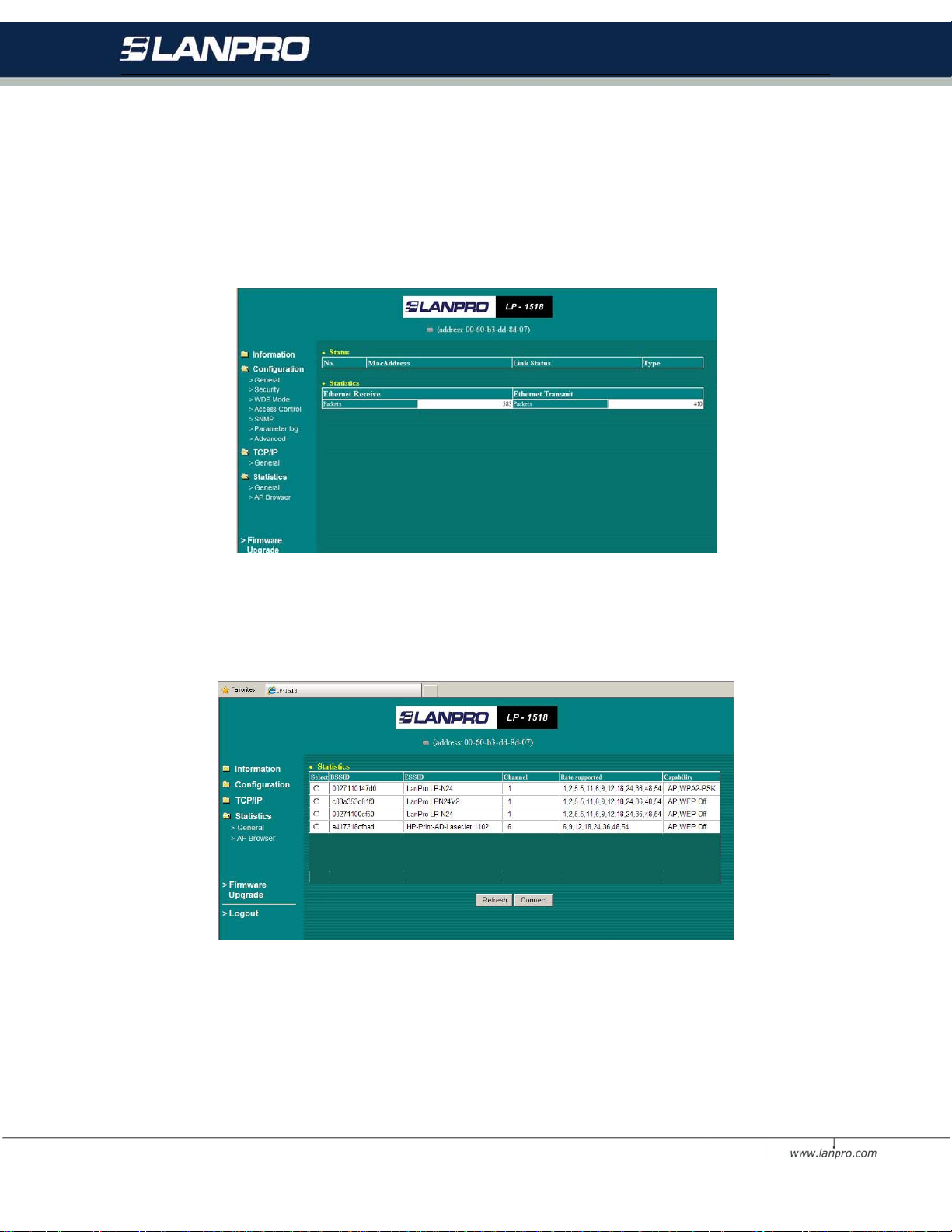
4.1.4 TCP/IP
You may assign a proper IP address to your wireless 3-in-1 AP manually. If you would like the wireless 3-in-1 AP to obtain
the IP addr ess from th e DHCP server on your network autom atically, en able th e DHCP client fun ction . Click the Apply
button t o make it effect. The default IP Address is 192.168.0.2.
When set to Client mode, you may also open the General page to view the available Access Points around your
environment. The status includes Link Status, ESSID, BSSID, Channel and Signal as well as RX/TX from Ethernet
packets.
19
Page 20
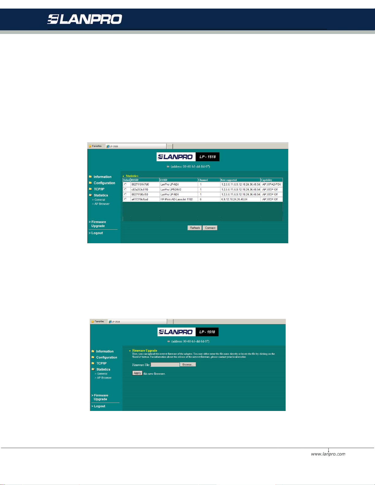
4.1.5.2 AP Browser Page
This AP Browser shows only when configuring your 3-in-1 AP as Station mode. By clicking the Refresh button, the
AP Browser will reload and display available Access Points around the working environment. Besides showing the
BSSID of each Access.
Point, it also displays ESSID, Channel, Support Rate and Capability. To connect one of displayed Access Points,
just select the Access Point you desire and then click the Connect button to make the connection.
4.1.5 Firmware Upgrade
Here, you can upload the latest firmware of the wireless 3-in-1 AP. You may either enter the file name in the entry
field or browse the file by clicking the Browse button. Then click the Apply button to begin to upgrade the new
firmware.
20
Page 21
4.2 Using the 3-in-1 AP Utility
Install the wireless 3-in-1 AP on your Windows 98/ME/2000/XP desktop computer, the Windows-based utility
Smart Utility provides an easy-setup interface. The Smart Utility enables you to configure your 3-in-1 AP on the
network more easily than ever before. The following gives instructions guiding you through the installations of the
Access Po in t Util ity.
1. Insert the Product CD-ROM or floppy disk that came with your product kit into the corresponding drive on
your computer.
2. Go to the Smart Utility folder and click Setup.exe. The installation screen will show up. Click Next to
continue.
3. Follow the on-screen instructions to install the Smart Utility.
4. Upon completion, go to Program Files and execute the Wireless Utility. It will begin to browse the 3-in-1
AP on the network.
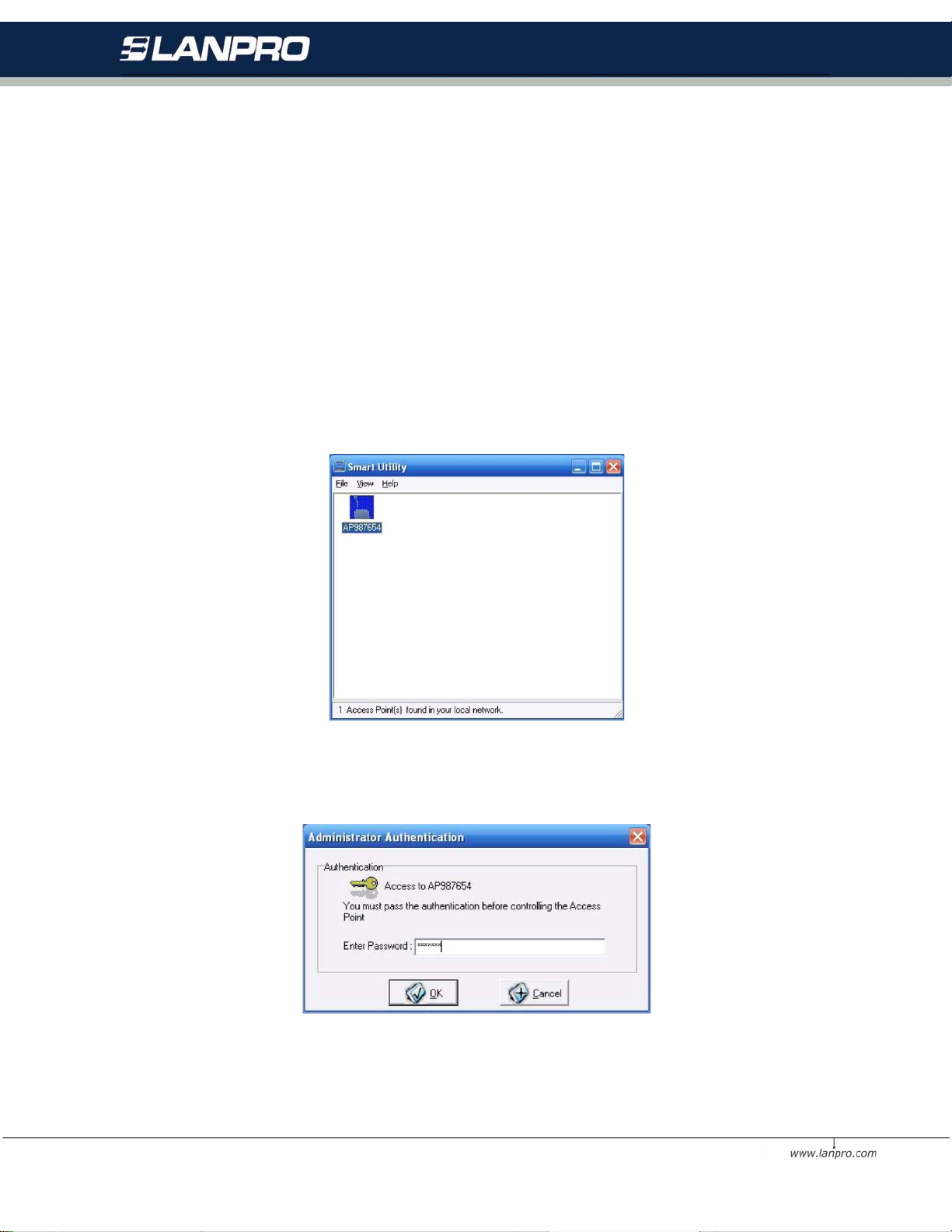
5. Double-click the AP987654 icon to access the property dialog box. Enter the password in the entry field.
The default password is default.
6. After entering the correct password, a main window appears. You will see the basic information of the
3-in-1 AP, such as MAC Address, Firmware, Boot and Utility version.
21
Page 22
MAC Ad dres s: It is a hardware identification number that distinguishes the unit from others. You will see this
number on the sticker of the 3-in-1 AP.
Firmware Version: Displays the firmware version that is equipped with your hardware.
4.2.1 Configuration
4.2.1.1 General Page
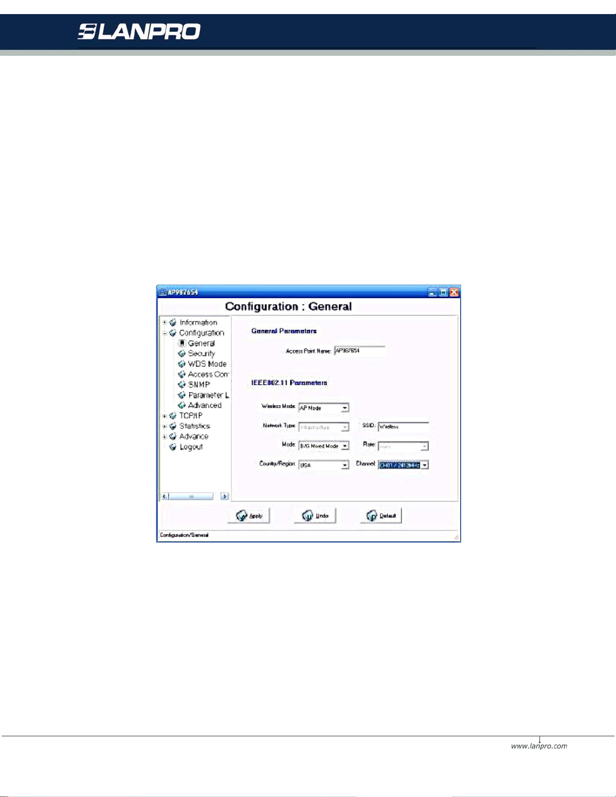
You may make the settings on your 3-in-1 AP such as Access Point Name, W ireless Mode, Network Type, SSID, Rate, Country/Region, Channel.
4.2.1.2 Security Page
To p revent unauthorized wireless stations from accessing data transmitted over the network, typically the sm art
utility provides W EP Encryption (Wired Equivalency P rivacy). You can sel ect Security Mode, Authentication Type
and Key Format whatever you want but make sure that the key value must be the same on both access point and
client side. Choose one of the 4 WEP keys to encrypt your data. Of course, WPA-PSK is included for advanced
security.
22
Page 23
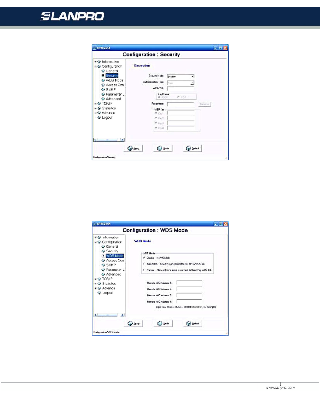
4.2.1.3 W DS Mode Pa ge
Here, you can extend the range of a wireless network. Wireless clients can associate with the WDS mode to
communicate with each client on your network.
23
Page 24
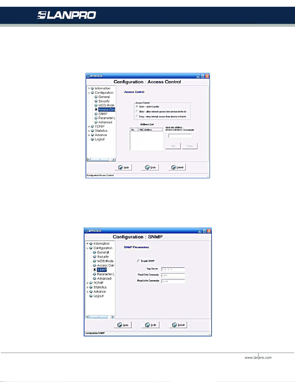
4.2.1. 4 A cc ess Contr o l Pag e
The Access Control page enables you to authorize wireless units accessing your 3-in-1 Access Point by identifying
the MAC Address of the wi reless devices.
4.2.1.5 SNMP Page
Using the Simple Network Management protocol (SNMP) manage the 3-in-1 AP.
24
Page 25
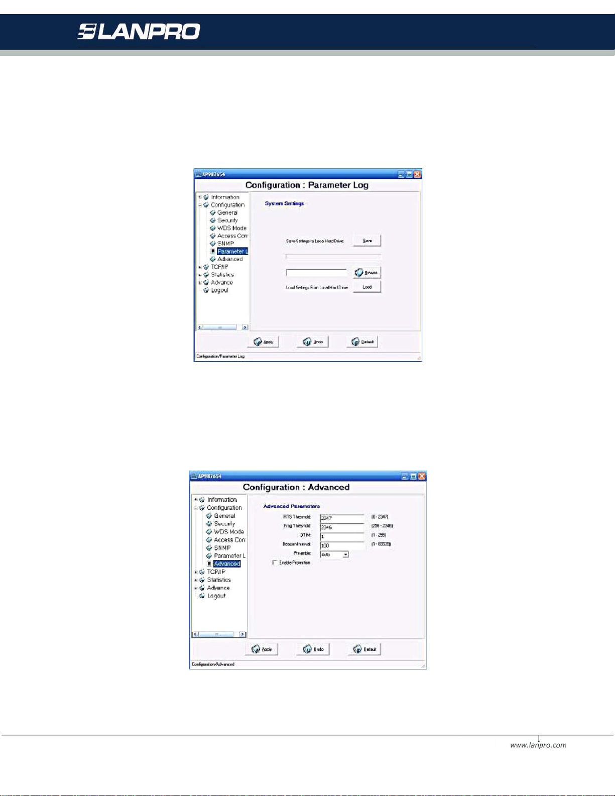
4.2.1. 6 P arameter Log Page
The Parameter log item allows you to save settings to the local hard drive by clicking Save. W hen you click the
Browse button, you can select the saved setting files. To click Load, the saved settings will be loaded back.
4.2.1. 7 A dvanced Pa ge
Here, you could modify some 802.11 advanced parameters. But if you do not know about them, you could leave
them keeping default status.
25
Page 26
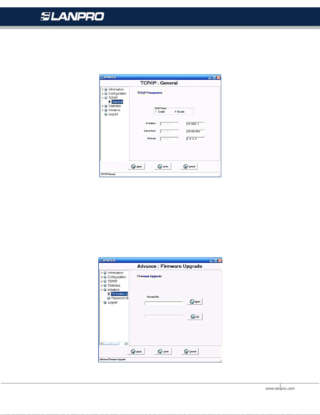
4.2.2 TCP/IP
The TCP/IP page lets you set this device IP address. The device can be configu r ed to use an automatic ( DHCP) address
or a fixed IP address.
4.2.3 A dv ance
4.2.3. 1 F ir m w are Upgrad e Page
This item i s used for uploading the newest firmware of the 3-in-1 AP. You may either enter the file name in the
entry field or browse the file by clicking the Open button and then click Go to run the upgrading. For information
about the release of the newest firmware, please contact your local reseller.
26
Page 27
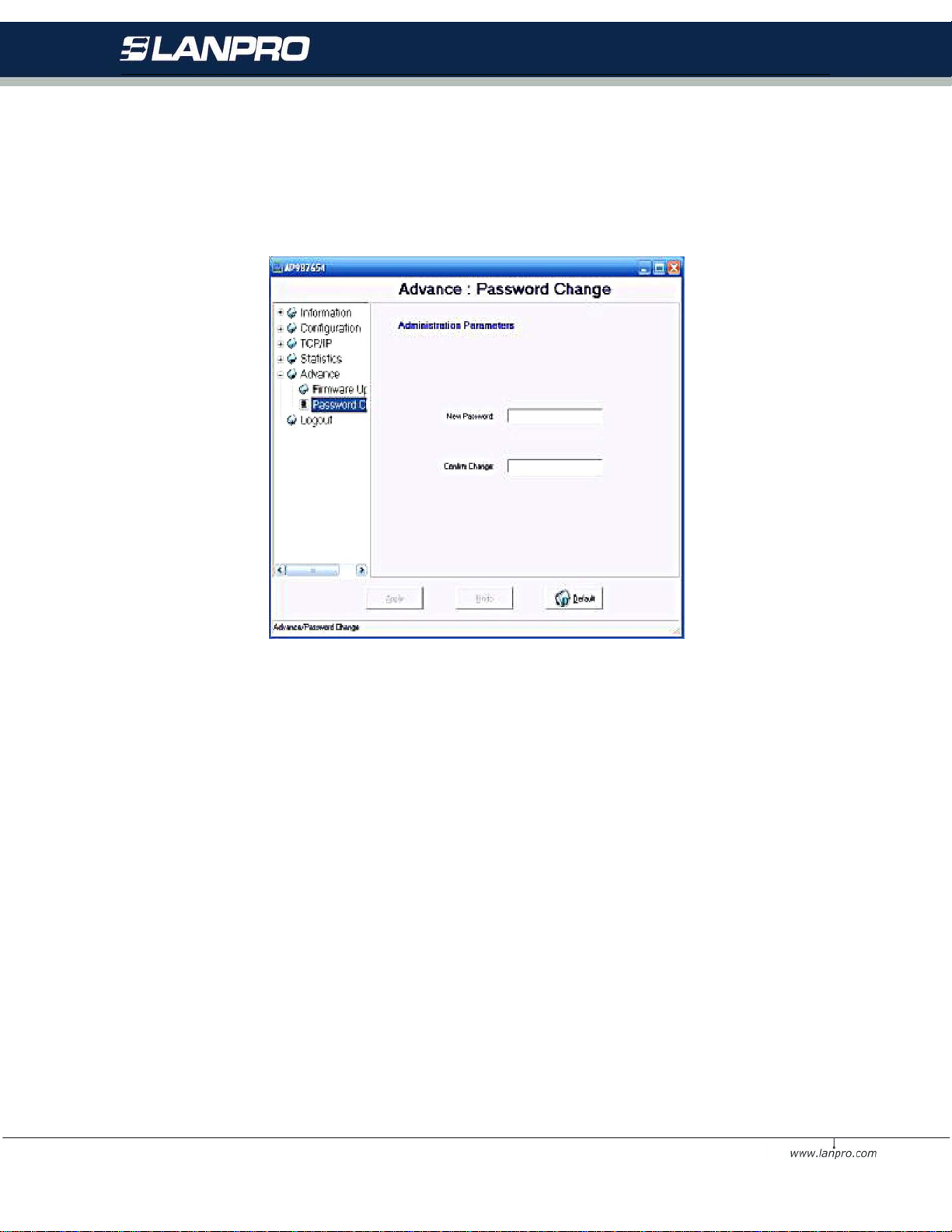
4.2.3. 2 P as s word Change Pag e
You may change the default password by entering the new password.
27
Page 28
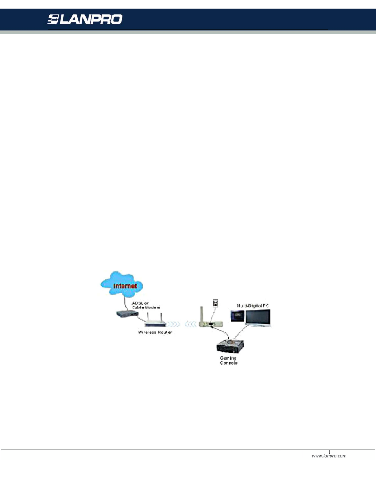
5 Wireless Connection to the Internet /Head-to-Head for your Gaming Console
Would you like to wirelessly enjoy playing games? The 3-in-1 AP can be act as a wireless gaming adapter for you
to game online through the Internet or to play with your friend (Head to Head gaming) in the same house. Select
one of the following and follow the installation steps accordingly.
5.1 Internet Gaming
1. The gaming adapter must be configured for your w ireless network on your PC before connecting it to your
gaming console.
2. Login to the Web User Interface and set your gaming adapter as Infrastructure mode, type your wireless
network SSID in the ESSID field and click Apply to make settings take effect.
3. Make sure that the connection between your gaming adapter and wireless router/access point is ok.
4. Connect one end of the Ethernet cable to the Wireless Gami ng Adapter’s LAN port and then connect the
other end of the cable to the Ethernet port on your gaming console.
5. Power on all units and make sure the gaming adapter is working properly.
6. Once you have configured your gaming adapter, you need to configure your gaming console. For
configuration details, refer to the documentation for your gaming console.
7. Start to enjoy playing gaming online through the Internet.
5.2 Head To Head Gaming
First, you may need to have a pair of gaming adapters for your gaming consoles. Be sure that both gaming adapters must
be configu r ed the sam e settings.
28
Page 29
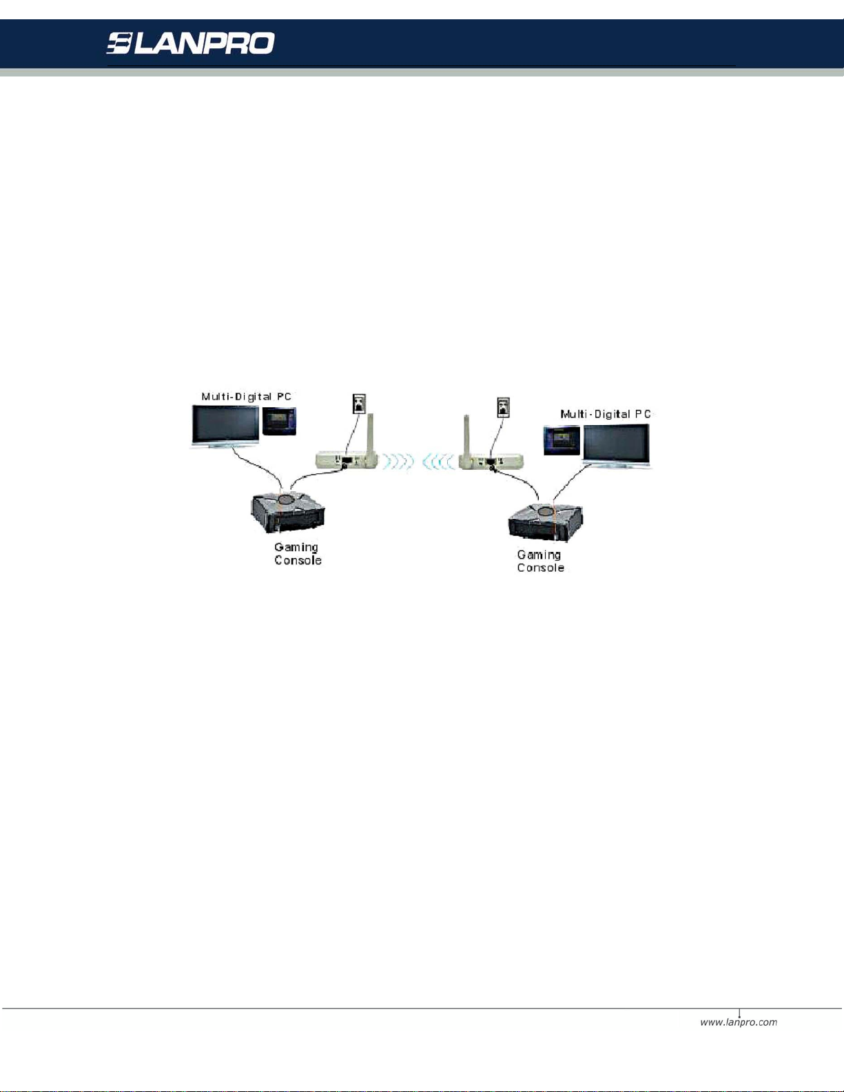
1. Both gaming adapt er s must be configured for your wireless net wor k on your PC before connecting them to your
gaming consoles.
2. Login to the Web User Interf ace and set both gaming adapters as Ad-Hoc mode, be sure that the same ESSID,
Chann el and Mode are configured on both gaming adapters and then cl ick Apply to m ake settings take effect.
3. Make sure that the connection between both of your gaming adapter is successful.
4. Connect one end of the Ethernet cable to the Wireless Gaming Adapter’s LAN port and th en connect the other
end of the cable to the Ethernet port on your gaming console. Hardware installation is the same on both gaming
adapters.
5. Power on all units and m ake sure both gaming adapt er s ar e ok.
6. Once you have configured both gaming adapters, you need to configure your gaming consoles. For
conf igur ation details, refer to the docum entat ion for your gaming console.
7. Start to enjoy pl aying Head to Head Gaming.
29
Page 30
6 Troubleshooting
Q1: Why can’t I connect to Internet?
1. Make sure that the com puter has a unique IP address. If using DHCP through the AP, verify that each
computer is set to Obtain an IP address automatically and restart the computer.
2. Make sure that the AP’s Ethernet is on. If it is not, try a different network cable.
Q2: Why can’t I access my Wireless LAN 3-in-1?
1. Make sure your 3-in-1 AP is powered on.
2. Make sure that your computer has a compatible IP address and that the IP address used on your
computer is within the range of 192.168.0.X.
3. Or reset to default settings and try to access again.
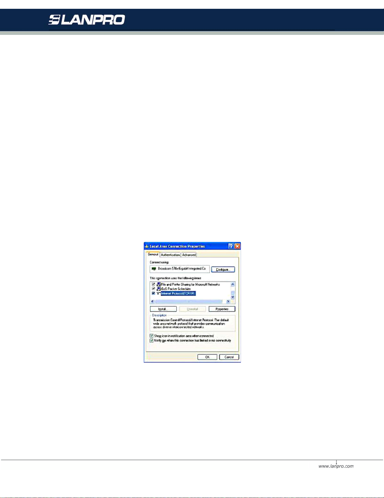
Q3: How to assign an IP address in Windows XP/200 0?
1. Go to Start > >Control Panel >> Network Connections > Right-click on Local Area Connections > Click
Properties .
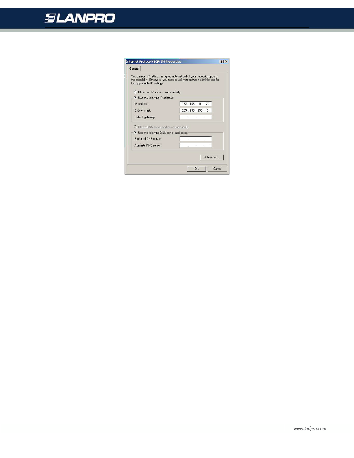
2. Highlight Internet Protocol (TCP/IP) and then click Properties.
Select Use the foll owing IP address in the Internet Protocol (TCP/IP) Properties window. Set your IP address
and subnet mask. (The IP Address must be within the same range as your 3-in-1 AP. The IP Address of your
3-in-1 AP is 192.168.0.2. You can assign 192.168.0.100 for your computer. No two computers can have the same
IP Address. Assign a subnet mask of (255.255.255.0.) and then Click OK button.
30
Page 31
Q4: How can I reset My Wireless L AN 3-in-1 AP to factory default?
1. Follow th ese st eps to perfor m a Factor y Reset using the Def ault but ton on the back of the 3-in-1 AP.
• With the unit on, press and hold the Default button with a pen or paper clip.
• Hold the Default button for about 3 seconds unt il the status LED on the front panel go off and then release.
• Wait a few second s for the 3-in-1 AP to reboot to default sett ings.
2. A Factory Reset can be also perfor med thr ough the Smart Utility interface. Foll ow th ese st eps to per form a
factor y reset using the Smart Utility configuration.
• Login the Smart Utility configuration interface.
• Click on the Default button.
• Click O K to pr oce ed and then th e 3-in-1 AP will be reset.
Q5: What should I do if I forget my password?
The only way is to restore factory configuration to this Wireless3-in-1 AP . Pl ease r efer to Q4.
Q6: Why can’t I access the Wireless LAN 3-in-1 AP from a wireless network card?
1. Make sure that Mod e, SSID, Channel and encryption settings are set the sam e on each wireless device.
2. Make sure that your computer is within the range and free from any strong electrical devices that m ay cause
interference.
3. Check your IP address and be sur e that it is compat ible with the wireless adapter.
Q7: How do I know I my computer is connected to the wireless LAN 3-in-1 AP ?
1. Try to following pr oced ur e Click Start-> Programs-> Accessories-> Command prompt.
2. At your MS-DOS prompt, your can use the ping command to check if your computer has successfully connected
to the wireless LAN 3-in-1 AP.
31
Page 32

3. Execute the ping command: ping 192.168.0.2.
4. Check if you can access the wireless LAN 3-in-1 AP’s configur ation page b y typing 192.168.0.2 in the location
(for IE) or Address f ield
32
Page 33

Appendix A Limited Warranty
This W arranty constitutes the sole and exclusi ve rem edy of any buyer or resell er’s equipment and the sole and
exclusive liability of the supplier in connection with the products and is in lieu of all other warranties, express,
implied or statutory, including, but not limited to, any implied warranty of merchantability of fitness for a particular
use and all other obligations or liabilities of the supplier.
In no even will the supplier or any other party or person be liable to your or anyone else for any damages, including
lost profits, lost savings or other incidental or consequential damages, or inability to use the software provided on
the software media even if the supplier or the other party person has been advised of the possibility of such
damages.
The following are special terms applicable to your hardware warranty as well as services you may use during part
of the warranty period. Your formal Warranty Statement, including the warranty applicable to our Wi reless LAN
products, appears in the Quick Installation Guide that accompanies your products.
Duration of Hardware Warranty: One Year
Replacement, Repair or Refund Procedure for Hardware:
If your unit needs a repair or replacement, return it to your dealer/distributor in its original packaging. When
returning a defective product for Warranty, always include the following documents:
• The Warranty Repair Card
• A copy of the invoice/proof of purchase, and
• The RMA Report Form (To receive a Return Materials Authorization form (RMA), please contact the party
from whom you purchased the product).
Upon proof-of-purchase we shall, at its option, repair or replace the defective item at no cost to the buyer.
This warranty is contingent upon proper use in the application for which the products are intended and does
not cover products which have been modified without the reseller’s approval or which have been subjected to
unusual physical or electrical demands or damaged in any way.
33
Page 34

Name:
Title:
Company:
Telephone:
Fax:
Email:
City/State/Zip co d e:
Country:
Product Name:
Serial Number:
MAC Ad dres s:
Invoice Date:
Product Description:
Please complete the informatio n below and include it along with your products.
If you have any further questions, please contact your local authorized reseller for support.
34
 Loading...