

Page 1

Embedded &
Industrial Computing
Hardware Platforms for Embedded and Industrial Computing
LEC-7230M
V1.1
User's Manual
Release date: 2016/11/28
Page 2
Overview
Icon Descriptions
The icons are used in the manual to serve as an
indication of interest topics or important messages.
Below is a description of these icons:
NOTE: This check mark indicates
that there is a note of interest and is
something that you should pay special
attention to while using the product.
WARNING: This exclamation point
indicates that there is a caution or
warning and it is something that could
damage your property or product.
Online Resources
The listed websites are links to the on-line product
information and technical support.
Resource Website
Lanner http://www.lannerinc.com
Product Resources
http://www.lannerinc.com/
download-center/
RMA http://eRMA.lannerinc.com
Copyright and Trademarks
This document is copyrighted, © 2014. All rights are
reserved. The original manufacturer reserves the right to
make improvements to the products described in this
manual at any time without notice.
No part of this manual may be reproduced, copied,
translated or transmitted in any form or by any means
without the prior written permission of the original
manufacturer. Information provided in this manual
is intended to be accurate and reliable. However, the
original manufacturer assumes no responsibility for its
use, nor for any infringements upon the rights of third
parties that may result from such use.
Acknowledgement
Intel, Pentium and Celeron are registered trademarks of
Intel Corp.
Microsoft Windows and MS-DOS are registered
trademarks of Microsoft Corp.
All other product names or trademarks are properties of
their respective owners.
Compliances and Certification
CE Certication
This product has passed the CE test for environmental
specifications. Test conditions for passing included
the equipment being operated within an industrial
enclosure. In order to protect the product from being
damaged by ESD (Electrostatic Discharge) and EMI
leakage, we strongly recommend the use of CEcompliant industrial enclosure products.
FCC Class A Certication
This equipment has been tested and found to comply
with the limits for a Class A digital device, pursuant
to Part 15 of the FCC Rules. These limits are designed
to provide reasonable protection against harmful
interference when the equipment is operated in a
commercial environment. This equipment generates,
uses and can radiate radio frequency energy and, if not
installed and used in accordance with the instruction
manual, may cause harmful interference to radio
communications. Operation of this equipment in a
residential area is likely to cause harmful interference
in which case the user will be required to correct the
interference at his own expense.
Revision History
Version Date Revision
0.1 2015/06/30 Preliminary
Page 3

EMC Notice
This equipment has been tested and found to comply
with the limits for a Class A digital device, pursuant to Part
15 of the FCC Rules. These limits are designed to provide
reasonable protection against harmful interference when
the equipment is operated in a commercial environment.
This equipment generates, uses, and can radiate radio
frequency energy and, if not installed and used in
accordance with the instruction manual, may cause
harmful interference to radio communications. Operation
of this equipment in a residential area is likely to cause
harmful interference in which case users will be required
to correct the interference at their own expense.
Safety Guidelines
Follow these guidelines to ensure general safety:
• Keep the chassis area clear and dust-free before,
during and after installation.
• Do not wear loose clothing or jewelry that could get
caught in the chassis. Fasten your tie or scarf and roll
up your sleeves.
• Wear safety glasses/goggles if you are working
under any conditions that might be hazardous to
your eyes.
• Do not perform any action that creates a potential
hazard to people or makes the equipment unsafe.
• Disconnect all power by turning off the power and
unplugging the power cord before installing or
removing a chassis or working near power supplies
• Do not work alone if potentially hazardous
conditions exist.
• Never assume that power is disconnected from a
circuit; always check the circuit.
LITHIUM BATTERY CAUTION:
Risk of explosion could occur if battery is replaced by an
incorrect type. Please dispose of used batteries according
to the recycling instructions of your country.
• Installation only by a trained electrician or only by an
electrically trained person who knows all the applied
or related installation and device specifications..
• Do not carry the handle of power supplies when
moving to other place.
• The machine can only be used in a fixed location
such as labs or computer facilities.
Operating Safety
• Electrical equipment generates heat. Ambient air
temperature may not be adequate to cool equipment to
acceptable operating temperatures without adequate
circulation. Be sure that the room in which you choose to
operate your system has adequate air circulation.
• Ensure that the chassis cover is secure. The chassis design
allows cooling air to circulate effectively. An open chassis
permits air leaks, which may interrupt and redirect the flow
of cooling air from internal components.
Electrostatic discharge (ESD) can damage equipment and
impair electrical circuitry. ESD damage occurs when electronic
components are improperly handled and can result in complete
or intermittent failures. Be sure to follow ESD-prevention
procedures when removing and replacing components to avoid
these problems.
• Wear an ESD-preventive wrist strap, ensuring that it makes
good skin contact. If no wrist strap is available, ground
yourself by touching the metal part of the chassis.
• Periodically check the resistance value of the antistatic
strap, which should be between 1 and 10 megohms
(Mohms).
Rack Mounting Installation Environment Precaution
1. Elevated Operating Ambient - If installed in a closed
or multi-unit rack assembly, the operating ambient
temperature of the rack environment may be greater than
room ambient. Therefore, consideration should be given
to installing the equipment in an environment compatible
with the maximum ambient temperature (Tma) specified
by the manufacturer.
2. Reduced Air Flow - Installation of the equipment in a rack
should be such that the amount of air flow required for
safe operation of the equipment is not compromised.
Mechanical Loading - Mounting of the equipment in the
rack should be such that a hazardous condition is not
created due to uneven mechanical loading.
3. Mechanical Loading - Mounting of the equipment in the
rack should be such that a hazardous condition is not
achieved due to uneven mechanical loading.
4. Circuit Overloading - Consideration should be given to
the connection of the equipment to the supply circuit and
the effect that overloading of the circuits might have on
over-current protection and supply wiring. Appropriate
consideration of equipment nameplate ratings should be
used when addressing this concern.
5. Reliable Earthing - Reliable earthing of rack-mounted
equipment should be maintained. Particular attention
should be given to supply connections other than direct
connections to the branch circuit (e.g. use of power strips).”
Page 4

Consignes de sécurité
Suivez ces consignes pour assurer la sécurité générale :
• Laissez la zone du châssis propre et sans poussière
pendant et après l’installation.
• Ne portez pas de vêtements amples ou de bijoux qui
pourraient être pris dans le châssis. Attachez votre
cravate ou écharpe et remontez vos manches.
• Portez des lunettes de sécurité pour protéger vos
yeux.
• N’effectuez aucune action qui pourrait créer un
danger pour d’autres ou rendre l’équipement
dangereux.
•
• Coupez complètement l’alimentation en éteignant
l’alimentation et en débranchant le cordon
d’alimentation avant d’installer ou de retirer un
châssis ou de travailler à proximité de sources
d’alimentation.
• Ne travaillez pas seul si des conditions dangereuses
sont présentes.
• Ne considérez jamais que l’alimentation est coupée
d’un circuit, vérifiez toujours le circuit. Cet appareil
génère, utilise et émet une énergie radiofréquence
et, s’il n’est pas installé et utilisé conformément aux
instructions des fournisseurs de composants sans
fil, il risque de provoquer des interférences dans les
communications radio.
Avertissement concernant la pile au
lithium
• Risque d’explosion si la pile est remplacée par une
autre d’un mauvais type.
• Jetez les piles usagées conformément aux
instructions.
• L’installation doit être effectuée par un électricien
formé ou une personne formée à l’électricité
connaissant toutes les spécifications d’installation et
d’appareil du produit.
• Ne transportez pas l’unité en la tenant par le câble
d’alimentation lorsque vous déplacez l’appareil.
• La machine ne peut être utilisée qu’à un lieu fixe
comme en laboratoire, salle d’ordinateurs ou salle de
classe.
Sécurité de fonctionnement
• L’équipement électrique génère de la chaleur. La
température ambiante peut ne pas être adéquate
pour refroidir l’équipement à une température de
fonctionnement acceptable sans circulation adaptée.
Vérifiez que votre site propose une circulation d’air
adéquate.
• Vérifiez que le couvercle du châssis est bien
fixé. La conception du châssis permet à l’air de
refroidissement de bien circuler. Un châssis ouvert
laisse l’air s’échapper, ce qui peut interrompre et
rediriger le flux d’air frais destiné aux composants
internes.
• Les décharges électrostatiques (ESD) peuvent
endommager l’équipement et gêner les circuits
électriques. Des dégâts d’ESD surviennent lorsque
des composants électroniques sont mal manipulés et
peuvent causer des pannes totales ou intermittentes.
Suivez les procédures de prévention d’ESD lors du
retrait et du remplacement de composants.
- Portez un bracelet anti-ESD et veillez à ce qu’il soit
bien au contact de la peau. Si aucun bracelet n’est
disponible, reliez votre corps à la terre en touchant la
partie métallique du châssis.
Vérifiez régulièrement la valeur de résistance du
bracelet antistatique, qui doit être comprise entre 1 et
10 mégohms (Mohms).
Consignes de sécurité électrique
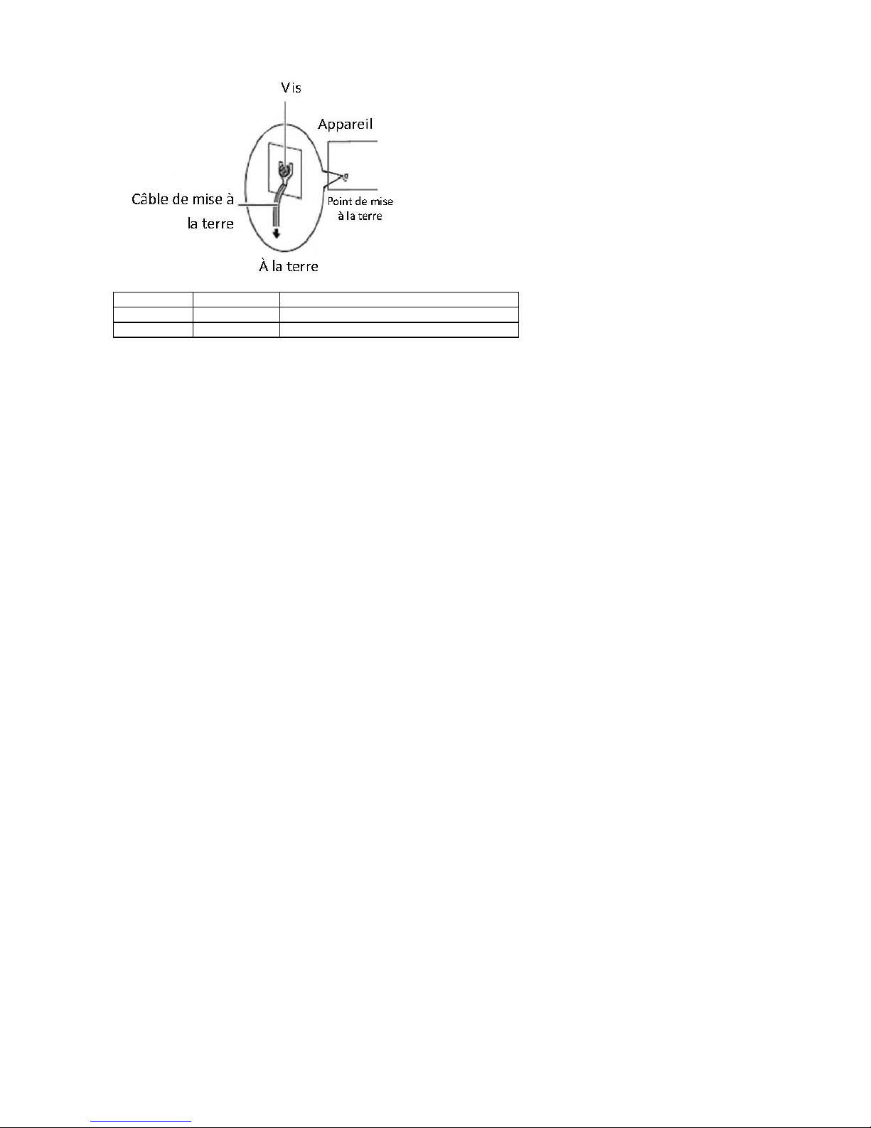
• Avant d’allumer l’appareil, reliez le câble de mise à la
terre de l’équipement à la terre.
• Une bonne mise à la terre (connexion à la terre) est
très importante pour protéger l’équipement contre
les effets néfastes du bruit externe et réduire les
risques d’électrocution en cas de foudre.
• Pour désinstaller l’équipement, débranchez le câble
de mise à la terre après avoir éteint l’appareil.
• Un câble de mise à la terre est requis et la zone
reliant les sections du conducteur doit faire plus de 4
mm2 ou 10 AWG.
Procédure de mise à la terre pour source
d’alimentation CC Procédure de mise à la
terre pour source d’alimentation CC
• Desserrez la vis du terminal de mise à la terre.
• Branchez le câble de mise à la terre à la terre.
• L’appareil de protection pour la source
d’alimentation CC doit fournir 30 A de courant.
Cet appareil de protection doit être branché à la
source d’alimentation avant l’alimentation CC.
Page 5
Version Date (Y/M/D) Description
1.0 2015/08/03 Ocial release
1.1 2015/12/28 Modied DB9 COM port pin denitions
Page 6

Table of Contents
Chapter 1: Introduction 7
System Specifications 7
Package Contents 8
Ordering Information 8
Block Diagram 9
Chapter 2: System Components 10
System Drawing 10
Front Components 11
Rear Components 12
Chapter 3: Board Layout 13
Jumpers & Connectors Locations 13
Connectors and Jumpers List 14
Jumper and Connectors Pinouts 15
Chapter 4: Hardware Setup 19
Preparing the Hardware Installation 19
Installing the System Memory 19
Installing CompactFlash card 20
Installing Mini-PCIe Module 20
Installing SIM Card 20
Installing the Disk Drive 21
Wallmounting for LEC-7230M 22
Appendix: Terms and Conditions 23
Page 7
Chapter 1:
Introduction
Thank you for choosing Lanner LEC-7230M This product
is a cost effective embedded system which adopts Intel
Bay-Trail CPU to provide a satisfying performance with
lower power consumption structure for any embedded
application. LEC-7230M’s compact fan-less design
incorporates many integrated multimedia and IO features
such as video, audio, network, and serial functions for
multiple purposes. This is one time-to-market system
allowing easy installation and replacement for most
systems.
The following highlight the features of the LEC-7230M
system:
• Intel Bay Trail-J1900 CPU
• Robust Fan-less enclosure and compact size
• DDR3L memory support up to 8GB
• 1x Mini-PCIe with SIM-card reader
• Dual 10/100/1000Mbps Ethernet ports
• USB: USB3.0 Type-A x1, USB2.0 Type-A x2
• Serial: 2 x RS232/422/485 COM ports
• Storage: 1x CF card socket and 1x SATA port for 2.5”
SATA HDD/SSD
• Single system power +12VDC input
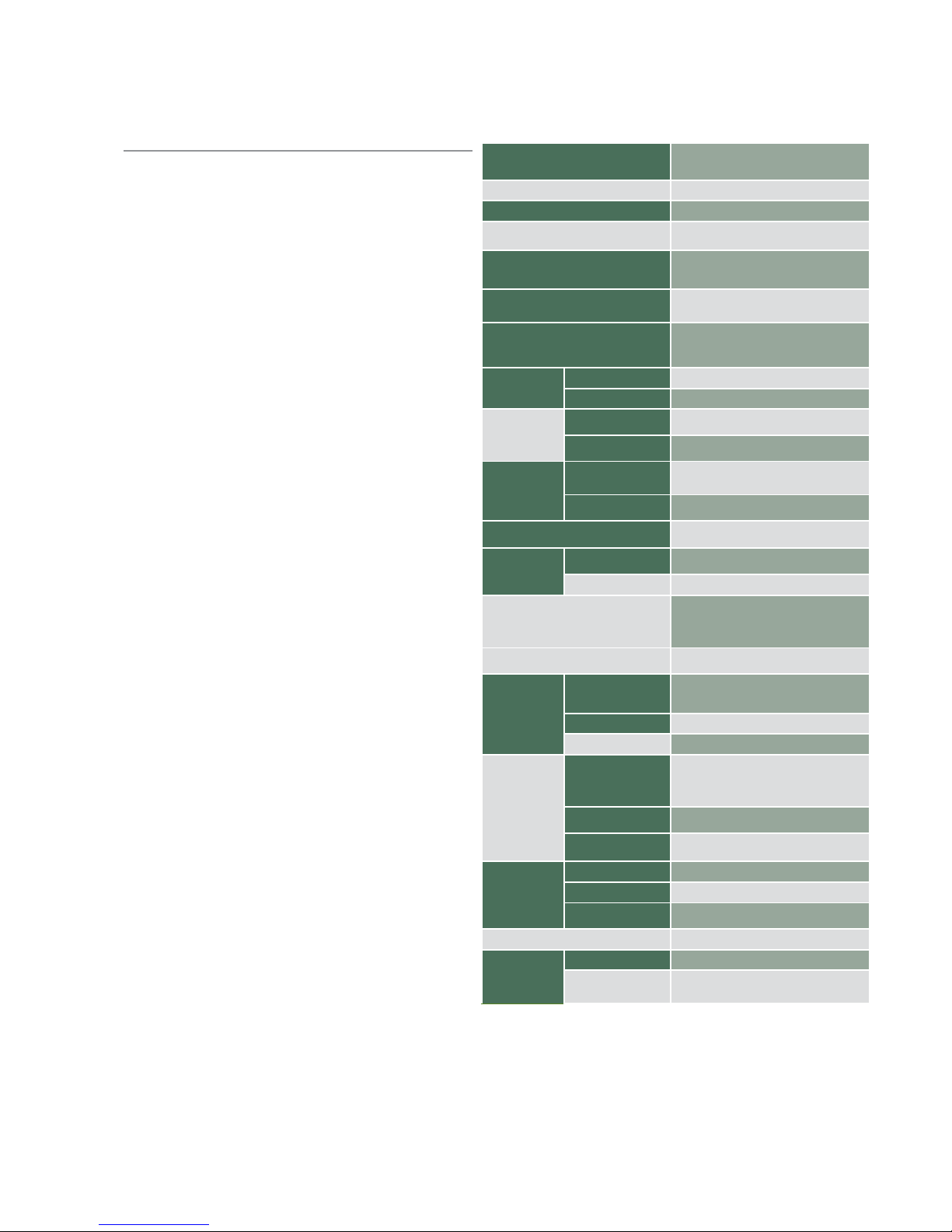
System Specifications
Processor Options
Intel® Celeron® J1900 (2M Cache, up to
2GHz) (10W)
Chipset None
BIOS AMI SPI Flash BIOS
System Memory
1x 204 pin SO-DIMM socket to support up to
1333MHz 8GB DDR3L SDRAM
USB
1x USB 3.0 Type-A port
2x USB 2.0 Type-A ports
Expansion Bus
1 x Mini-PCIe socket (PCIexpress 1x and USB
2.0), with SIM card reader
Operating Systems
Windows: WE 8.1 Industry Pro, WES7, Win7
Pro FES (32/64bit)
Linux: Fedora 18 later
Storage
HDD/SSD Support 1 x 2.5” HDD/SSD drive bay
NAND Flash 1 x CompactFlash Type I/II socket
Networking
LAN
2 x RJ-45 10/100/1000Mbps, Autosensing
ports
Controller
2x Intel® Ethernet Controller i211-AT;
Support PXE
Display
Graphics Controller Intel® Integrated Graphics
Outputs
HDMI: 1920x1080
VGA: 1600x1200 @60 24bpp
Serial
2x DB9 Male (COM1/2) supporting RS-232/422/485
Audio
Ports
2x Audio I phone jack connectors for Mic and
line-out
Codec Realtek ALC662 HD Audio
LEDs
1x triple-stack LEDs; Yellow for storage-access
status, green for power-on status,
the other green for 3G status if 3G mini-card
exists
Buttons
1 x Power 0n/Off button
1 x Reset switch
Physical
Characteristics
Housing
Top cover is Aluminum extrusion for main
heat dissipation
Chassis body made by SGCC
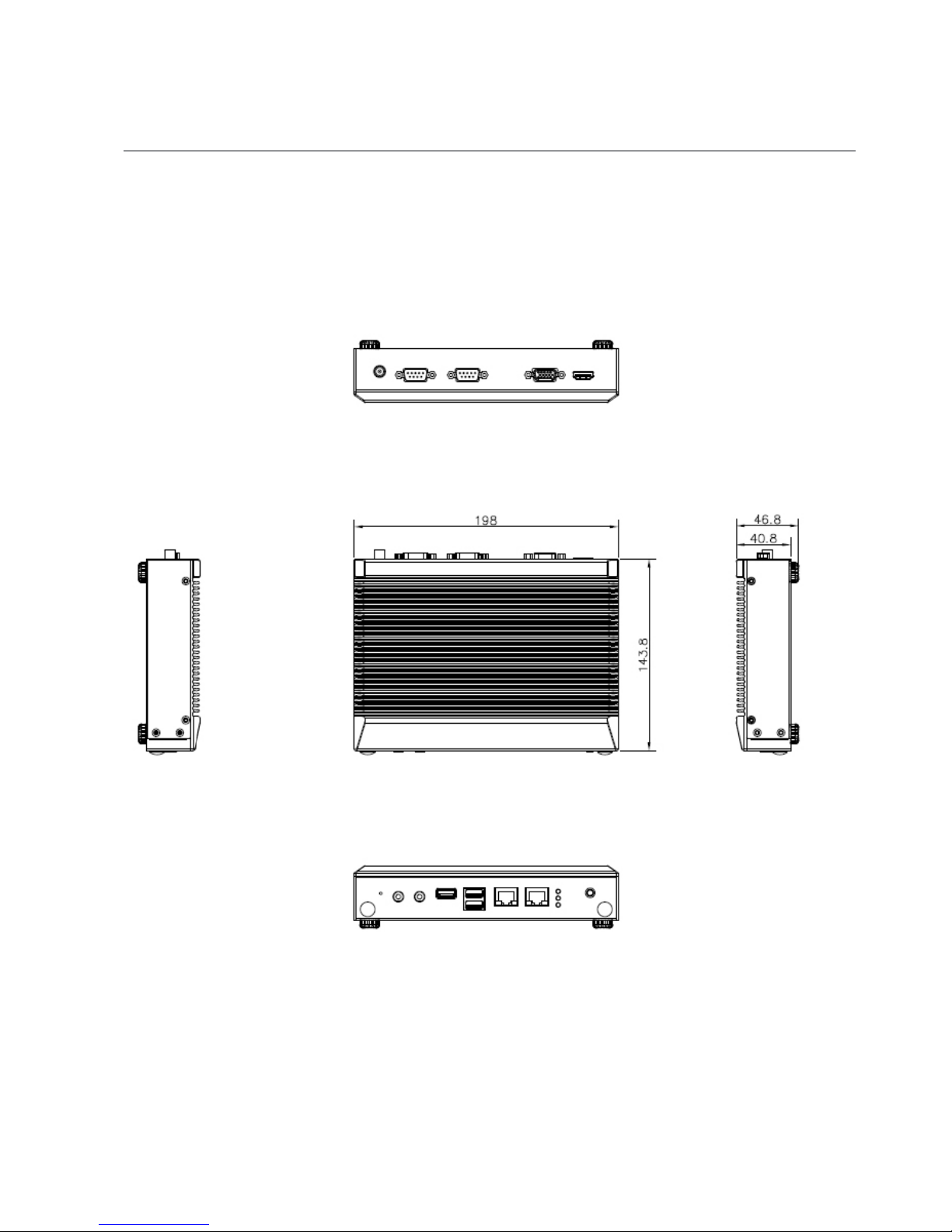
Dimensions (WxHxD) 198 x 40.8x 143.8 , unit: mm
Mounting Options Rack, VESA, DIN-rail and Wall mount
Environment
Operating Temperature
0°C~40°C with industrial grade storage and
memory
Non-operating
Temperature
-20°C~70°C
Humidity
(non-condensing)
5 to 95% (non-condensing)
Power
Input Voltage DC+12V +/- 5% input
Connector DC Jack w/Lock
Adapter
AC to DC, AC 90 to 240 V AC Input,
DC 12VDC /5A 60W
Certications CE, FCC, UL
Reliability
Thermal Fanless
WDT
Watchdog Timer 256 level time interval
system reset, software programmable
Page 8

Package Contents
Your package contains the following items:
• LEC-7230M Fanless Embedded System
• Power adapter
• Drivers and User’s Manual CD
Ordering Information
LEC-7230M-J11A Fanless Industrial PC with Intel® Celeron® J1900 2GHz
Processor
Page 9
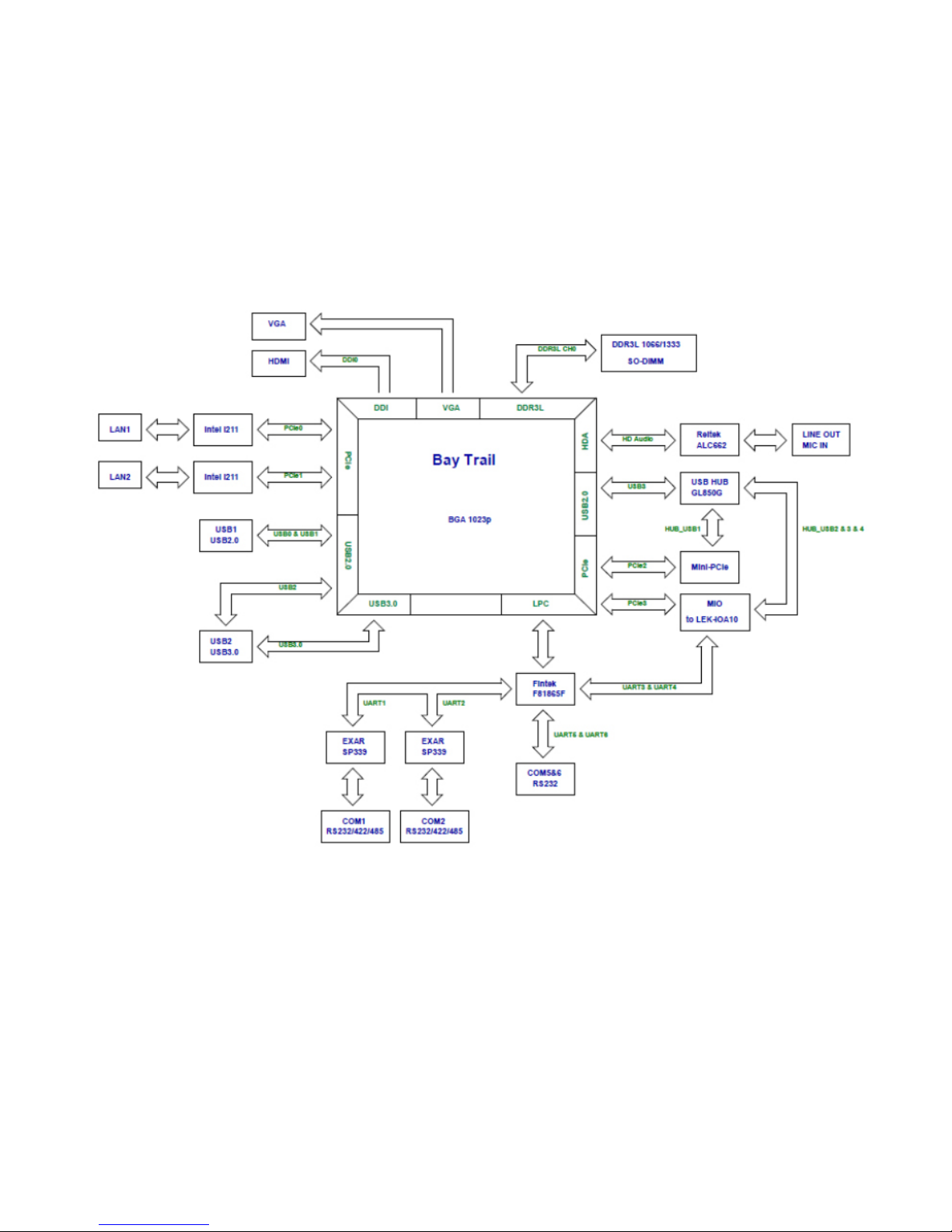
Block Diagram
Page 10
Chapter 2:
System Components
System Drawing
Mechanical dimensions of the LEC-7230M
Unit: mm
Page 11
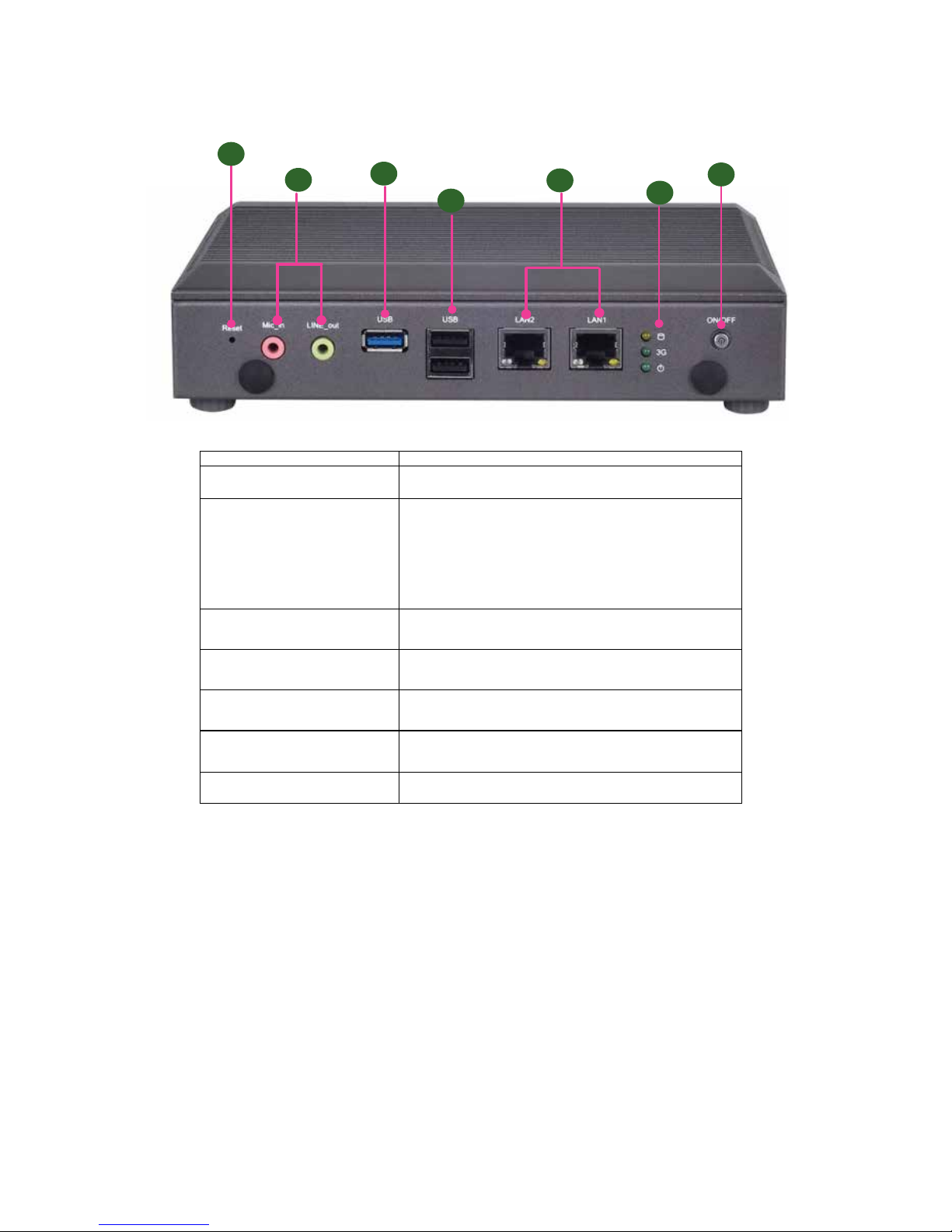
Component Description
F1 Power On/Off Button Power the system on/off
F2 LED indicators
1 x triple-stacked LEDs
• Yellow for storage access status
• Green for power-on status
• the other green for 3G/4G/LTE status if a 3G/4G/LTE
module is installed
F3 Two LAN ports 2x RJ45 with LED connectors for 10/100/1000Mbps
F4 Double-stacked USB ports 2x USB 2.0 Type-A ports in double-stacked form
F5 USB 3.0 port 1 x USB 3.0 Type-A port
F6 Mic_In/Line_Out
1x green phone-jack connector for audio line-out
1x pink phone-jack connector for audio mic-in
F7 Reset 1 x Reset switch
Front Components
F3
F1
F2
F5
F6
F7
F4
Page 12
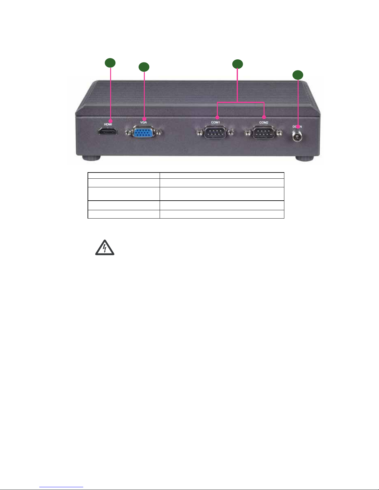
Rear Components
R1
R2
Component Description
R1 DC_IN 1x DC Jack W/lock for DC +12Vdc input
R2 Serial
2 x DB9 Serial COM ports supporting RS232/422/485
R3 VGA 1 x VGA display port
R4 HDMI 1 x HDMI 1.4a output
R3
R4
WARNING: Improper installation can cause injury or property damage.
For proper and safe operation use in field site with AC
Power, please follow these instructions:
1. Securely plugged and locked the DC-Jack to the machine
2. Connect the AC adapter power cord into a standard 110v/220v AC outlet
Page 13
Chapter 3:
Board Layout
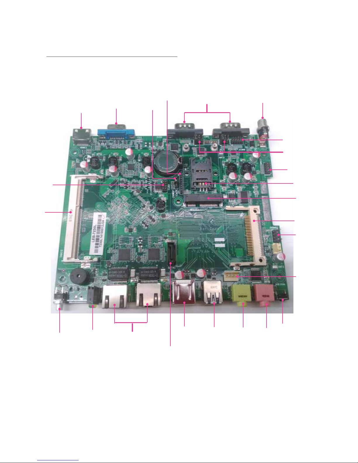
Jumpers & Connectors Locations
HDMI1
VGA1
COM1,2
DCJACK1
LAN1,2
JRI1,2
JCOM6
JCOM5
DIMM1
USB1
USB2
LOUT1
MIC1
RSTBTN1
PSBTN1
SATA1
SATAPWR1
JKBMS1
CF1
MPCIE1
SIM1
LED1
JSPI1
JCMOS1
JLPC1
Page 14
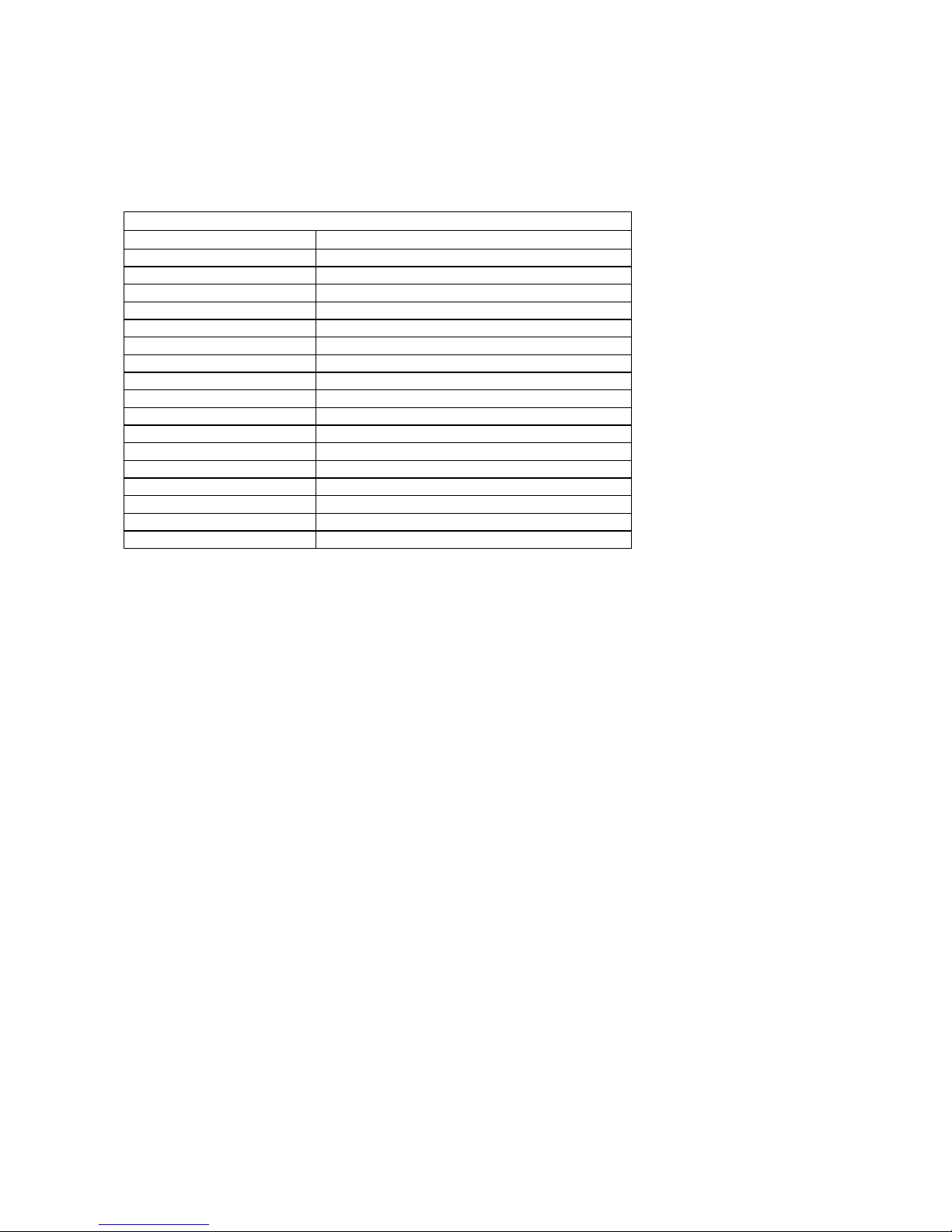
Connectors and Jumpers List
The tables below list the function of each of the board jumpers and connectors by labels shown in the above
section. The next section in this chapter gives pin definitions and instructions on setting jumpers.
Table 3.1 Connector List for LEB-7230M Board
Labels Function
COM1/COM2 RS-232/422/485 Serial Ports
HDMI1 High-Denition Multimedia Interface Port
JCMOS1 Clear CMOS Jumper
JKBMS1 PS/2 Keyboard & Mouse Connector
JLPC1 Low-pin Count Interface
JRI1/2 COM1/COM2 Pin 9 Signal Selection
JSPI1 SPI ROM Interface (for debug use only)
MPCIE1 Mini-PCIe Connectors (with SIM1)
SATA1 Serial-ATA Connector (SATA1)
SATAPWR1 SATA HDD Power Connector
SIM1 SIM Card Reader
USB1 USB 2.0 Type A Dual Port
USB2 USB 3.0 Type A Port
VGA1 VGA Connector
LAN1,2 Ethernet LAN ports at 10/100/1000 Mbs
CF1 CompactFlash socket supporting Type I/II
MIC1/LOUT1 Mic_In and Line_Out audio ports
Page 15
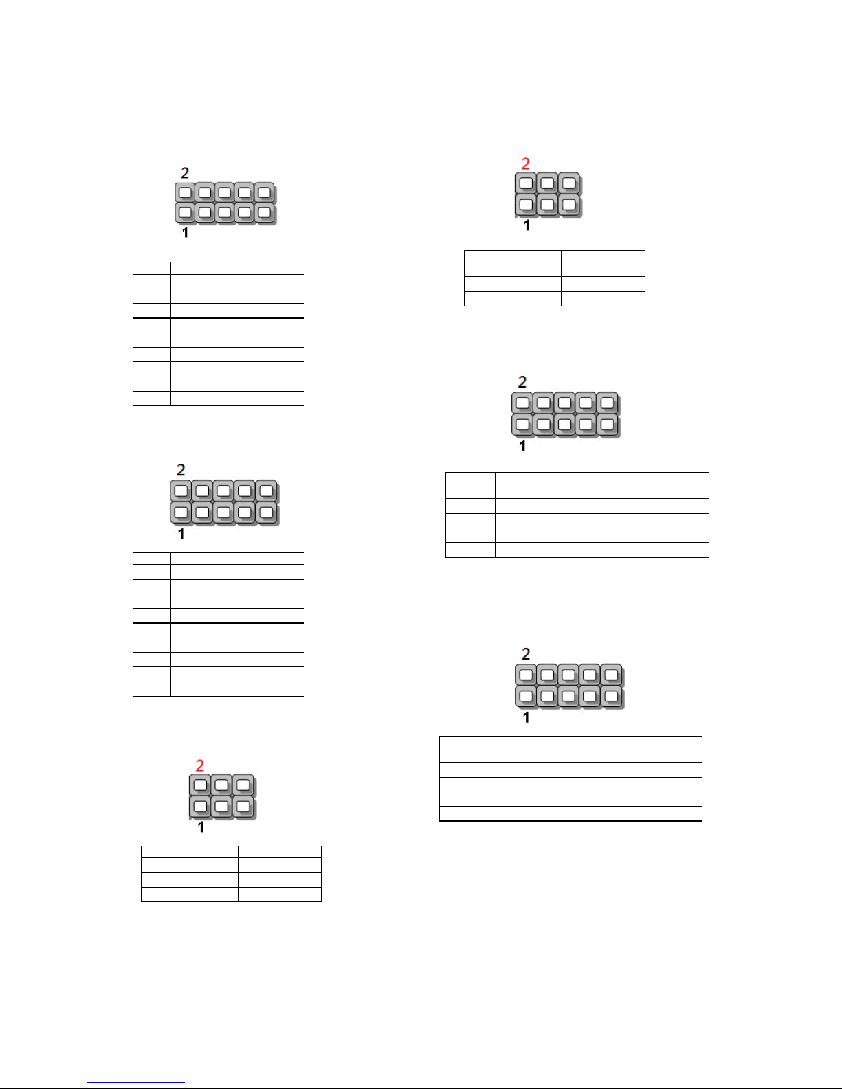
Jumper and Connectors Pinouts
JCOM5: RS-232 pin header
JCOM6: RS-232 pin header
JRI1: pin header for COM1 Pin9 signal selection
Pin No. Signal
1 DCD#
2 DSR#
3 RXD
4 RTS#
5 TXD
6 CTS#
7 DTR#
8 RI#
9 GND
Pin No. Signal
1 DCD#
2 DSR#
3 RXD
4 RTS#
5 TXD
6 CTS#
7 DTR#
8 RI#
9 GND
Pin Signal
1-2 short (Default) RI#
3-4 short +5V
5-6 short +12V
JRI2: pin header for COM2 Pin9 signal selection
JLPC1: LPC (Low-Pin-Count) pin header for debug uses
JSPI1: SPI pin header
Pin Signal
1-2 short (Default) RI#
3-4 short +5V
5-6 short +12V
Pin Signal Pin Signal
1 CLK 2 AD1
3 RESET# 4 AD0
5 FRAME# 6 +3.3V
7 AD3 8 GND
9 AD2 10 GND
Pin Signal Pin Signal
1 HOLD# 2 NC
3 CS# 4 +1.8V
5 MISO 6 NC
7 NC 8 CLK
9 GND 10 MOSI
Page 16
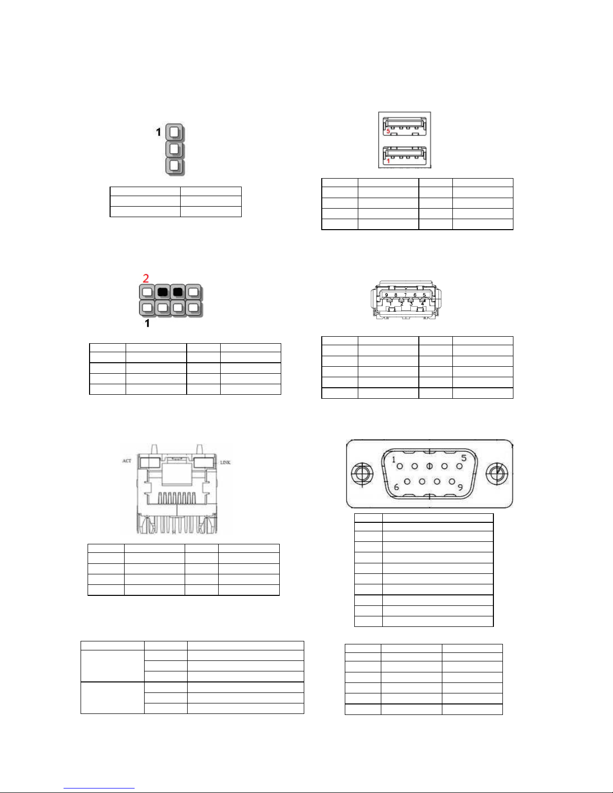
JCMOS1: CMOS jumper to select “Normal” condition or to
clear CMOS setting
JKBMS1: PS/2 keyboard and mouse pin header
LAN1, 2: 2 x RJ-45 Ethernet LAN ports at
10/100/1000Mbps
LED indicators as described below:
Pin Signal
1-2 short (Default) Normal
2-3 short Clear CMOS
Pin Signal Pin Signal
1 VCC 2 MSCLK
3 MSDATA 4 KEY
5 KBDATA 6 KEY
7 GND 8 KBCLK
Pin Signal Pin Signal
1 MDI0+ 2 MDI03 MDI1+ 4 MD12+
5 MD12- 6 MDI17 MDI3+ 8 MDI3-
LED Status/Color Status Description
ACT/Orange Off LAN link is not established
On LAN link is established
Blinking LAN activity is ocurring
Link/Green/Orange Off 10 Mbits/sec data rate is selected
On/Green 100 Mbits/sec data rate is selected
On/Orange 1000 Mbits/sec data rate is selected
USB1: 1 x double-stacked USB 2.0 Type-A connectors
USB2: 1 x USB 3.0 Type-A connector
COM1, 2: 2 x DB9 Serial COM ports with RS-232/422/485
Pin Signal Pin Signal
1 +5V 2 DATA23 DATA2+ 4 GND
5 SSRX- 6 SSRX+
7 GND 8 SSTX9 SSTX+
RS-422 RS-485
Pin Signal Signal
1 TXD- DATA2 TXD+ DATA+
3 RXD+
4 RXD5 GND GND
Pin Signal Pin Signal
1 +5V 2 DATA13 DATA1+ 4 GND
5 +5V 6 DATA07 DATA0+ 8 GND
Pin No. Signal
RS-232
1 Data Carrier Detect ( DCD # )
2 Receive Data ( RXD )
3 Transmit Data ( TXD )
4 Data Terminal Ready ( DTR # )
5 Ground ( GND )
6 Data Set Ready ( DSR # )
7 Request To Send ( RTS # )
8 Clear To Send ( CTS # )
9 Ring Indicator ( RI # )
Page 17
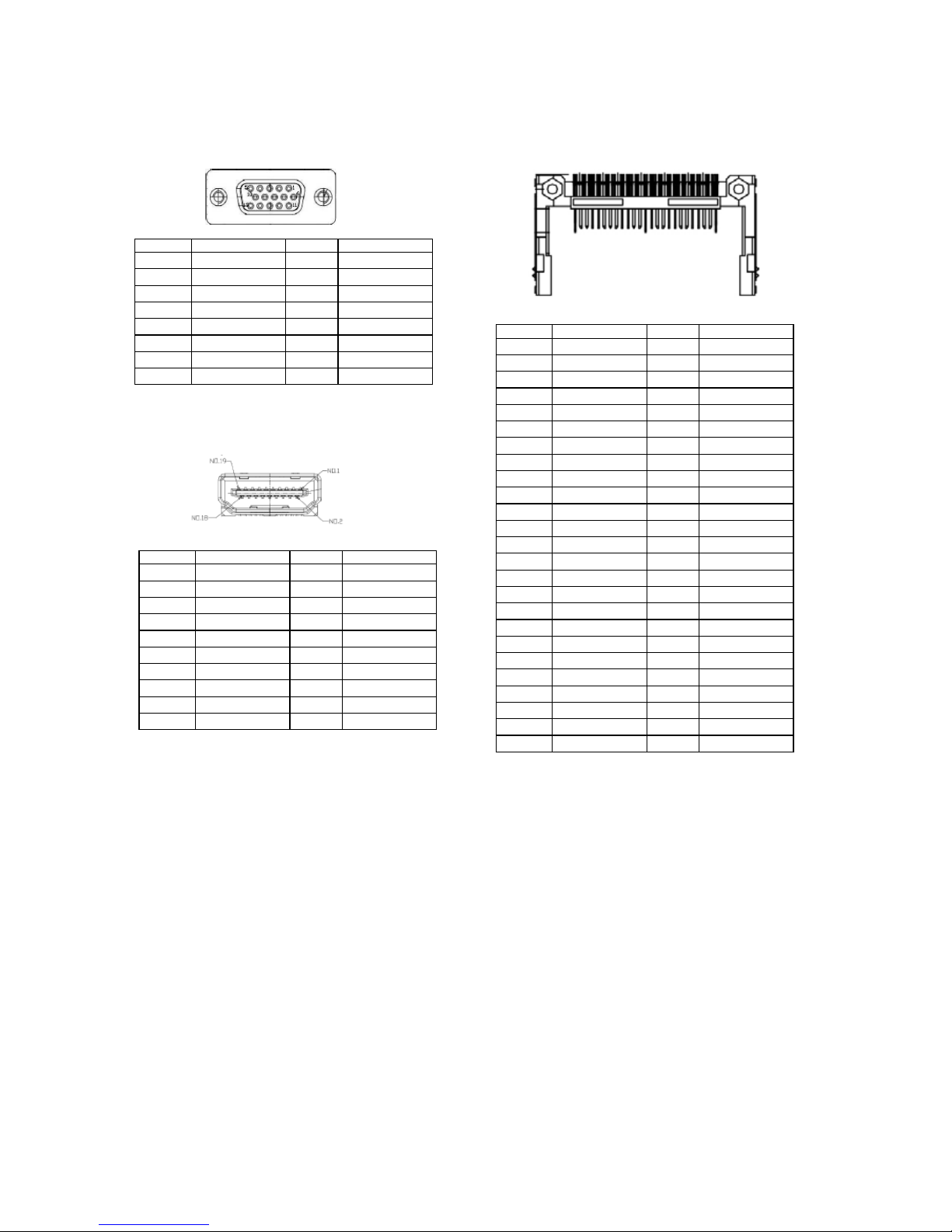
VGA1: 1 x VGA display port
HDMI1: 1 X HDMI 1.4a display port
Pin Signal Pin Signal
1 DATA2+ 2 GND
3 DATA2- 4 DATA1+
5 GND 6 DATA17 DATA0+ 8 GND
9 DATA0- 10 CLK+
11 GND 12 CLK13 NC 14 NC
15 DDC CLK 16 DDC DAT
17 GND 18 HDMI_VCC
19 HPD
Pin Signal Pin Signal
1 RED 9 +5V
2 GREEN 10 GND
3 BLUE 11 NC
4 Reserve 12 DDC_DATA
5 GND 13 HSYNC
6 GND 14 VSYNC
7 GND 15 DDC_CLK
8 GND
CF1: 1 x CompactFlash Type I/II slot
Pin Signal Pin Signal
1 GND 26 -CD1
2 D3 27 D11
3 D4 28 D12
4 D5 29 D13
5 D6 30 D14
6 D7 31 D15
7 -CS0 32 -CS1
8 A10 (GND) 33 -VS1
9 ATA_SEL# 34 -IORD
10 A9 (GND) 35 -IOWR
11 A8 (GND) 36 -WE
12 A7 (GND) 37 INTRQ
13 VCC 38 VCC
14 A6 (GND) 39 -CSEL
15 A5 (GND) 40 -VS2
16 A4 (GND) 41 -RESET
17 A3 (GND) 42 IORDY
18 A2 43 DMARQ
19 A1 44 -DDACK
20 A0 45 -DASP
21 D0 46 -PDIAG
22 D1 47 D8
23 D2 48 D9
24 -IOCS16 49 D10
25 -CD2 50 GND
Page 18
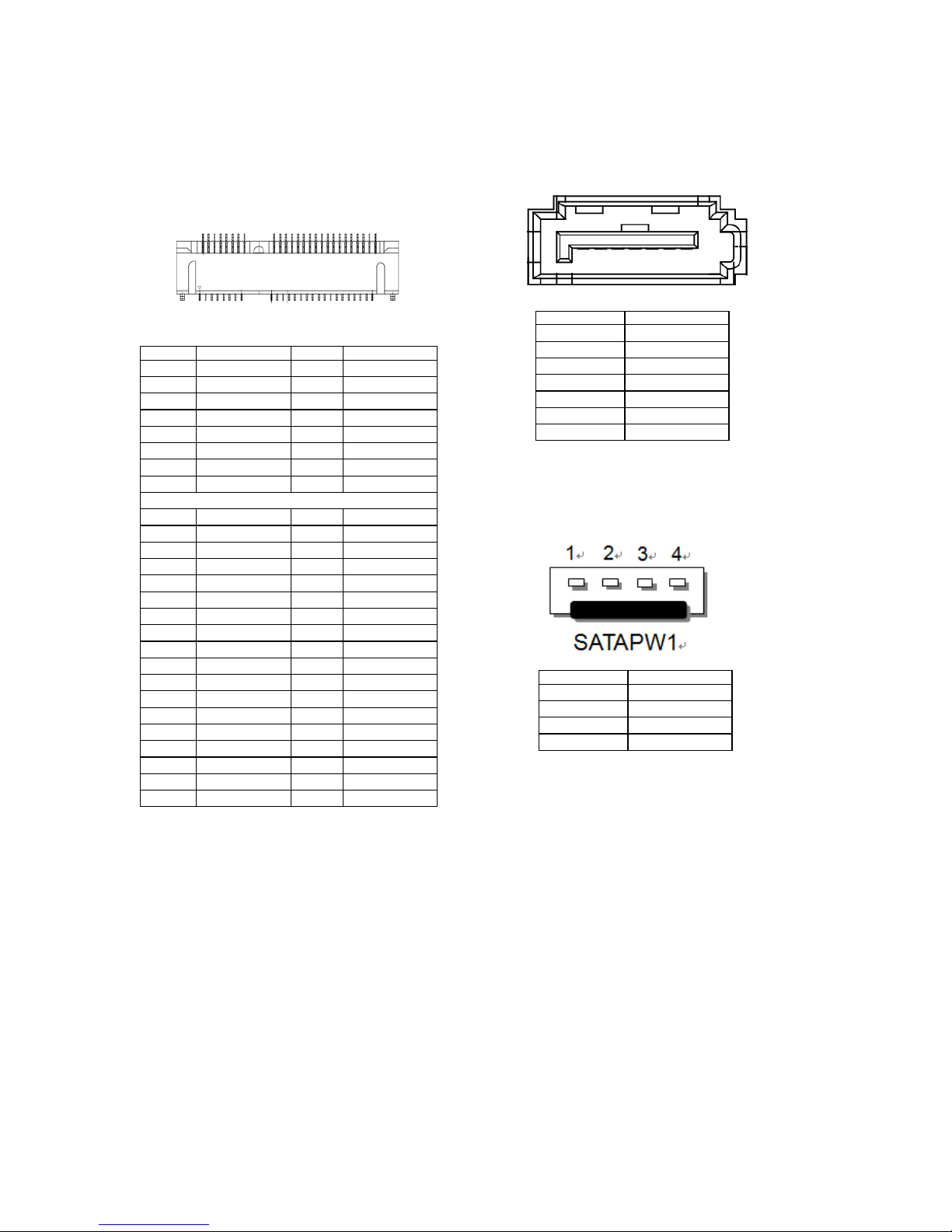
MPCIE1: 1 x Mini-PCIe socket (PCIexpress 1x and USB 2.0)
with SIM-card reader for 3G mini-card module
Pin Signal Pin Signal
1 WAKE# 2 +3.3Vaux
3 COEX1 4 GND
5 COEX2 6 +1.5V
7 CLKREQ# 8 UIM_PWR
9 GND 10 UIM_DATA
11 REFCLK- 12 UIM_CLK
13 REFCLK+ 14 UIM_RESET
15 GND 16 UIM_VPP
Mechanical Key
17 Reserve 18 GND
19 Reserve 20 W_DISABLE#
21 GND 22 PERST#
23 PERn0 24 +3.3Vaux
25 PERp0 26 GND
27 GND 28 +1.5V
29 GND 30 SMB_CLK
31 PETn0 32 SMB_DATA
33 PETp0 34 GND
35 GND 36 USB_D37 GND 38 USB_D+
39 +3.3Vaux 40 GND
41 +3.3Vaux 42 LED_WWAN#
43 GND 44 LED_WLAN#
45 Reserve 46 LED_WPAN#
47 Reserve 48 +1.5V
49 Reserve 50 GND
51 Reserve 52 +3.3Vaux
SATA1: 1 x SATA 7-pin signal connector for 2.5” storage
device
SATAPWR1: 1 x SATA 4-pin wafer connector for +5V DC
output as the power segment for 2.5” storage device
Pin Signal
1 GND
2 TXP
3 TXN
4 GND
5 RXN
6 RXP
7 GND
Pin Signal
1 +12V
2 GND
3 GND
4 +5V
Page 19
Chapter 4:
Hardware Setup
Preparing the Hardware Installation
To access some components and perform certain service
procedures, you must perform the following procedures
first.
WARNING:
Please remove all the power
connection before conducting the
following hardware installations.
It is strongly recommended to wear ESD
proof gloves for the following setups.
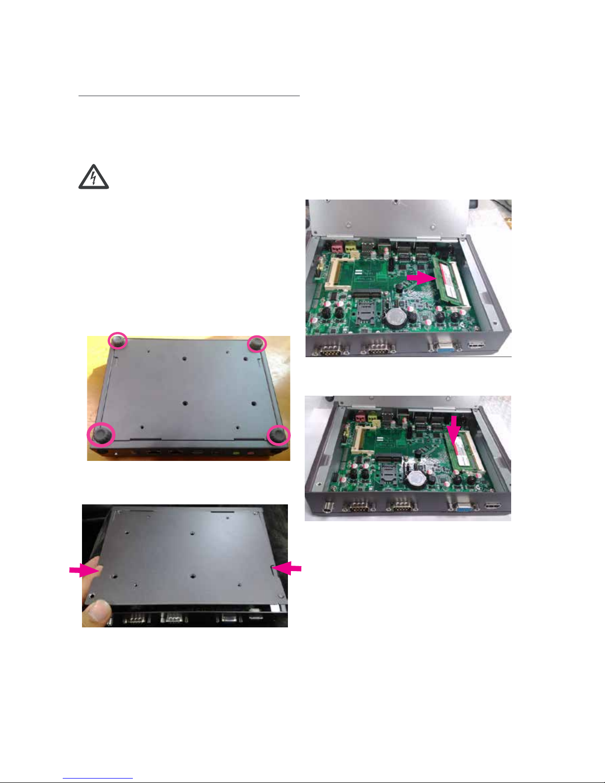
1. Turn LEC-7230M upside-down.
2. Loosen the 4 locking pads circled in the image below
and remove them from the bottom cover.
3. Use the notches on both sides to open the cover.
Installing the System Memory
Please follow the steps for installing the system memory
module.
1. Align the memory module’s key with the DIMM
module.
2. Install the DIMM module as shown in the image below.
3. Press the module down until it is clipped in.
Note:
The system can support memory of 204-pin SODIMM 1333MHz DDR3L SDRAM memory up to
8GB. Please install the module compatible with
this specification to ensure proper operations.
Page 20
Installing CompactFlash card
Please follow the steps for installing CompactFlash card
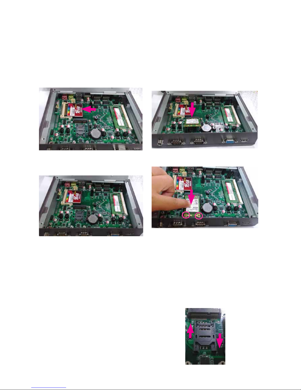
1. Align the female connector of your CF card to the male
connector of the CF slot on the motherboard.
2. Press the card into the slot until it is firmly seated.
Installing Mini-PCIe Module
1. Align the mini-PCIe module’s key with the Mini-PCIe
slot notch.
2. Insert the module diagnolly as shown in the picture
below.
3. Press it down and lock the module with 2 screws.
Installing SIM Card
1. Locate the SIM card reader socket beside the miniPCIe slot.
2. Slide the reader socket to open it. There is an arrow
showing the direction to open.
3. Tilt the socket and insert the SIM card.
4. Press it down and slide the reader socket to lock it.
There is an arrow showing the direction to lock.
Open
Lock
Page 21
Installing the Disk Drive
The system can accommodate one Serial-ATA disk drive.
Follow these steps to install a hard disk into the system:
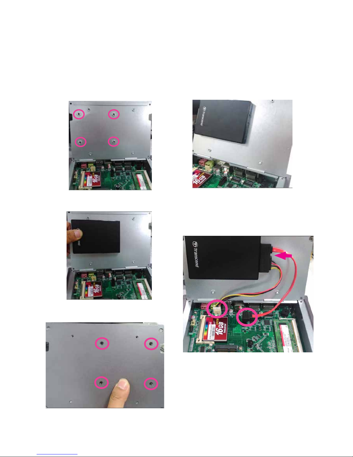
1. Locate the disk drive bay on the back side of the top
compartment.
2. Place the disk drive (HDD or SSD) as shown in the
image below.
3. Lock the disk drive from the other side of the cover and
apply four screws.
4. Your SATA disk drive should be placed as the image
below.
5. Connect the SATA cable as shown in the image below.
First, plug the SATA connector of the cable to the disk
drive, then place the 7-pin SATA signal connector and
the 4-pin SATA power connector to the corresponding
connectors on the motherboard.
Page 22
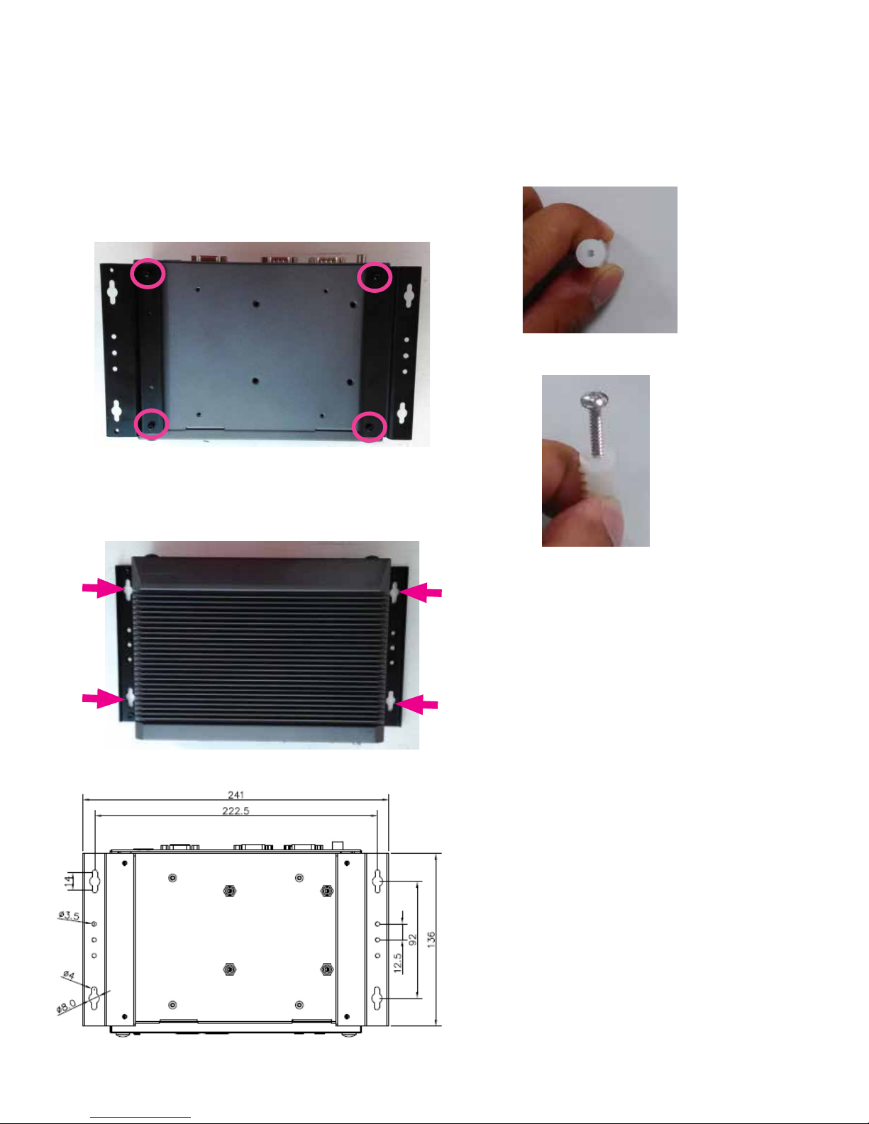
Wall Mounting for LEC-7230M
LEC-7230M can be mounted on a wall for operational
purposes. Please follow the steps below for wall
mounting.
1. Attach wall-mounting brackets to LEC-7230M. Align
the brackets to the system by matching the screw holes
circled below. Then, apply screw nails. The brackets
should be included in the shipped package.
2. Draw locations for applying hollow wall anchors. You
may use the 4 holes pointed by the arrows in the figure
below.
Another option is to refer to the diagram below.
4. Apply 4 wall anchors based on the locations drawn in
the last step.
5. Insert screw nails into the anchor.
6. Hang LEC-7070 onto the wall.
Page 23

Appendix:
Terms and Conditions
Warranty Policy
1. All products are under warranty against defects in
materials and workmanship for a period of one year
from the date of purchase.
2. The buyer will bear the return freight charges for
goods returned for repair within the warranty period;
whereas the manufacturer will bear the after service
freight charges for goods returned to the user.
3. The buyer will pay for repair (for replaced
components plus service time) and transportation
charges (both ways) for items after the expiration of
the warranty period.
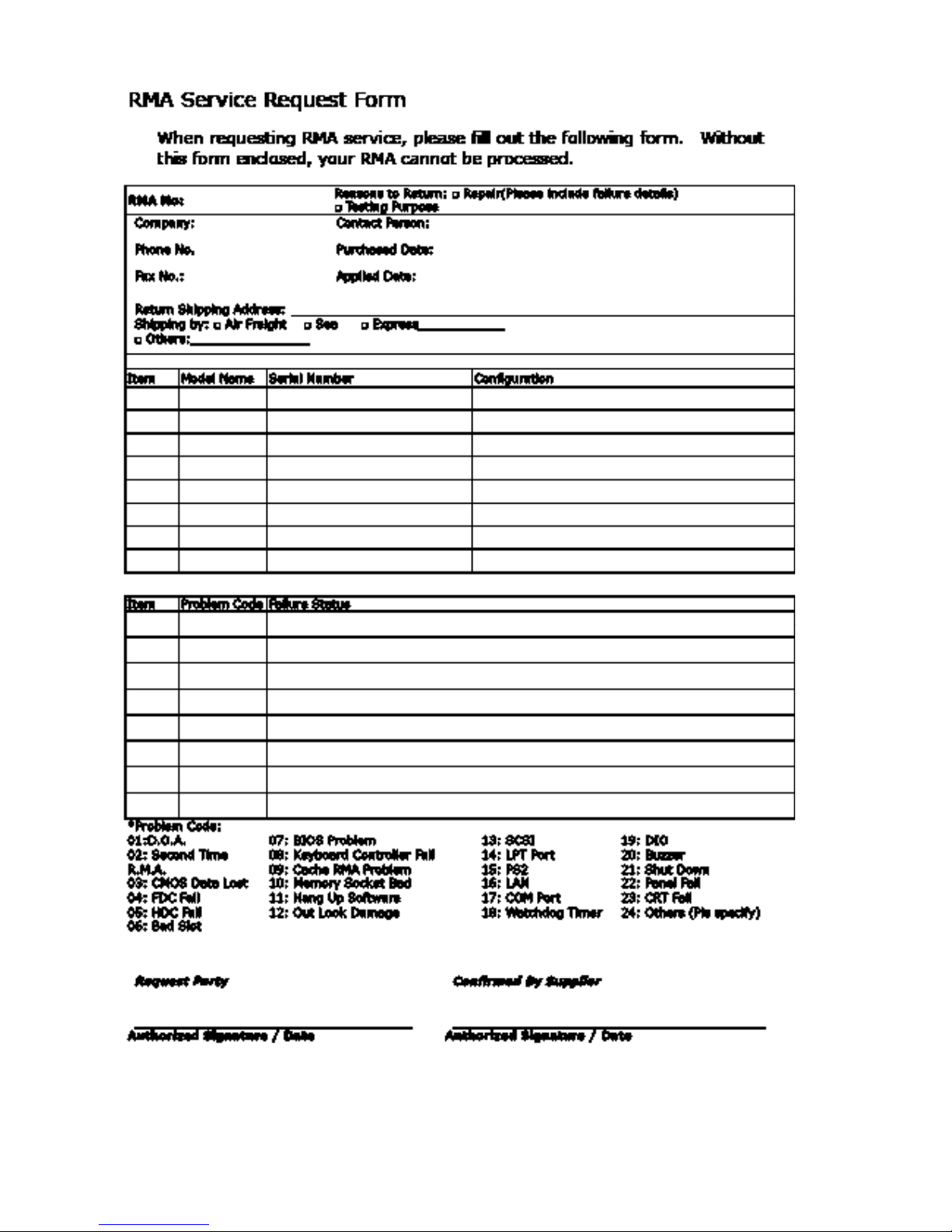
4. If the RMA Service Request Form does not meet the
stated requirement as listed on “RMA Service,” RMA
goods will be returned at customer’s expense.
5. The following conditions are excluded from this
warranty:
Improper or inadequate maintenance by the customer
Unauthorized modification, misuse, or reversed
engineering of the product Operation outside of the
environmental specifications for the product.
RMA Service
Requesting a RMA#
6. To obtain a RMA number, simply fill out and fax the
“RMA Request Form” to your supplier.
7. The customer is required to fill out the problem code
as listed. If your problem is not among the codes
listed, please write the symptom description in the
remarks box.
8. Ship the defective unit(s) on freight prepaid terms.
Use the original packing materials when possible.
9. Mark the RMA# clearly on the box.
Note: Customer is responsible for shipping
damage(s) resulting from inadequate/loose
packing of the defective unit(s). All RMA# are
valid for 30 days only; RMA goods received after
the effective RMA# period will be rejected.
Page 24
 Loading...