

Page 1

LEC-7000 Fanless Embedded System User’s Manual
LEC-7000 Series
Intel® Atom N270 (1.6Ghz) CPU onboard
Fanless Embedded System
User’s Manual
1
Page 2

LEC-7000 Fanless Embedded System User’s Manual
LEC-7000 Series
User’s Manual
© Copyright 2007, Lanner Electronics, Inc. All rights reserved. This document contains
proprietary information that is protected by copyright. No part of this document may be
reproduced, transmitted, transcribed, stored in a retrieval system, or translated into any
language in any form by any means without the written express of Lanner Electronics, Inc.
The author and Lanner Electronics, Inc. have used their best efforts in preparing this manual.
However, the author and Lanner Electronics, Inc. make no warranties of any kind, expressed
or implied, with regard to the informational content, documentation, or files contained in this
manual, and shall not be liable for technical or editorial errors or omissions contained herein.
In no event shall the author or publisher be responsible or liable for any incidental or
consequential damages resulting from the furnishing, performance, or use of this material.
TRADEMARKS Internet Explorer, Windows Explorer, and Windows are trademarks or registered
trademarks of Microsoft Corporation. Other products mentioned herein may be trademarks/or
registered trademarks of their respective owners.
2
Page 3

LEC-7000 Fanless Embedded System User’s Manual
Safety Guidelines
Follow these guidelines to ensure general safety:
z Keep the chassis area clear and dust-free during and after installation.
z Do not wear loose clothing or jewelry that could get caught in the chassis. Fasten your
tie or scarf and roll up your sleeves.
z Wear safety glasses if you are working under any conditions that might be hazardous to
your eyes.
z Do not perform any action that creates a potential hazard to people or makes the
equipment unsafe.
z Disconnect all power by turning off the power and unplugging the power cord before
installing or removing a chassis or working near power supplies
z Do not work alone if potentially hazardous conditions exist.
z Never assume that power is disconnected from a circuit; always check the circuit.
z LITHIUM BATTERY CAUTION:
Risk of Explosion if Battery is replaced by an incorrect type.
Dispose of used batteries according to the instructions.
Operating Safety
z Electrical equipment generates heat. Ambient air temperature may not be adequate to
cool equipment to acceptable operating temperatures without adequate circulation. Be
sure that the room in which you choose to operate your system has adequate air
circulation.
z Ensure that the chassis cover is secure. The chassis design allows cooling air to
circulate effectively. An open chassis permits air leaks, which may interrupt and
redirect the flow of cooling air from internal components.
Electrostatic discharge (ESD) can damage equipment and impair electrical circuitry. ESD
damage occurs when electronic components are improperly handled and can result in
complete or intermittent failures. Be sure to follow ESD-prevention procedures when
removing and replacing components to avoid these problems.
z Wear an ESD-preventive wrist strap, ensuring that it makes good skin contact. If no
wrist strap is available, ground yourself by touching the metal part of the chassis.
z Periodically check the resistance value of the antistatic strap, which should be between
1 and 10 megohms (Mohms).
3
Page 4

LEC-7000 Fanless Embedded System User’s Manual
EMC Notice
This equipment has been tested and found to comply with the limits for a Class A digital
device, pursuant to Part 15 of the FCC Rules. These limits are designed to provide reasonable
protection against harmful interference when the equipment is operated in a commercial
environment. This equipment generates, uses, and can radiate radio frequency energy and,
if not installed and used in accordance with the instruction manual, may cause harmful
interference to radio communications. Operation of this equipment in a residential area is
likely to cause harmful interference in which case users will be required to correct the
interference at their own expense.
Class A Notice for FCC
Modifying the equipment without the authorization of Lanner Electronics, Inc. may result in
the equipment no longer complying with FCC requirements for Class A digital devices. In that
event, your right to use the equipment may be limited by FCC regulations, and you may be
required to correct any interference to radio or television communications at your own
expense.
This equipment is in compliance with the essential requirements and other relevant
provisions of Directive 1999/5/EC.
4
Page 5

LEC-7000 Fanless Embedded System User’s Manual
Contents
Safety Guidelines ....................................................................... 2
EMC Notice ………………………………………………………………………..4
Contents……............................................................................... 5
1. Product Overview.................................................................. 6
1.1 Product Introduction ........................................................ 6
1.2 Features and Benefits....................................................... 6
1.3 Specifications ................................................................... 7
1.4 Block Diagram .................................................................. 8
1.5 Package Contents............................................................. 9
1.6 Technical Assistance......................................................... 9
2. System Components............................................................ 10
2.1 LEC-7000 (VES-402) System Board ................................. 10
2.1.1 Board Layout ................................................................ 11
2.1.1 Board Dimensions......................................................... 12
2.1.2 Jumper Settings and I/O Connectors ........................... 13
2.2.1 Connector Pin Assignments .......................................... 14
2.2 LEC-7000 Embedded System Mechanisms ...................... 19
2.2.1 Front View................................................................... 19
2.2.2 Rear View .................................................................... 20
3. Hardware Installation Guide ............................................... 21
3.1 LEC-7000 Embedded System .......................................... 21
3.1.1 Begin Installation......................................................... 21
3.1.2 System Memory Installation......................................... 22
3.1.3 CompactFlash Card Installation.................................... 22
3.1.4 HDD Installation........................................................... 23
3.1.5 System Complete.......................................................... 25
3.2 Mounting Kits ................................................................. 26
3.2.1 Wall Mount (Optional) .................................................. 26
3.2.2 VESA Mount (Optional)................................................. 27
3.2.3 Rack Mount Kit (Optional) ............................................ 27
A. Appendix A: LAN Port LED Indicators.................................. 28
B. Appendix B: Watchdog Timer .............................................. 29
B.1 Most Introduction.......................................................... 29
B.2 Detail Register Descriptions ........................................... 29
B.2.1 To used the watch-dog timer........................................ 29
Terms and Conditions............................................................... 30
Warranty Policy........................................................................ 30
RMA Service ............................................................................. 30
5
Page 6
LEC-7000 Fanless Embedded System User’s Manual
1. Product Overview
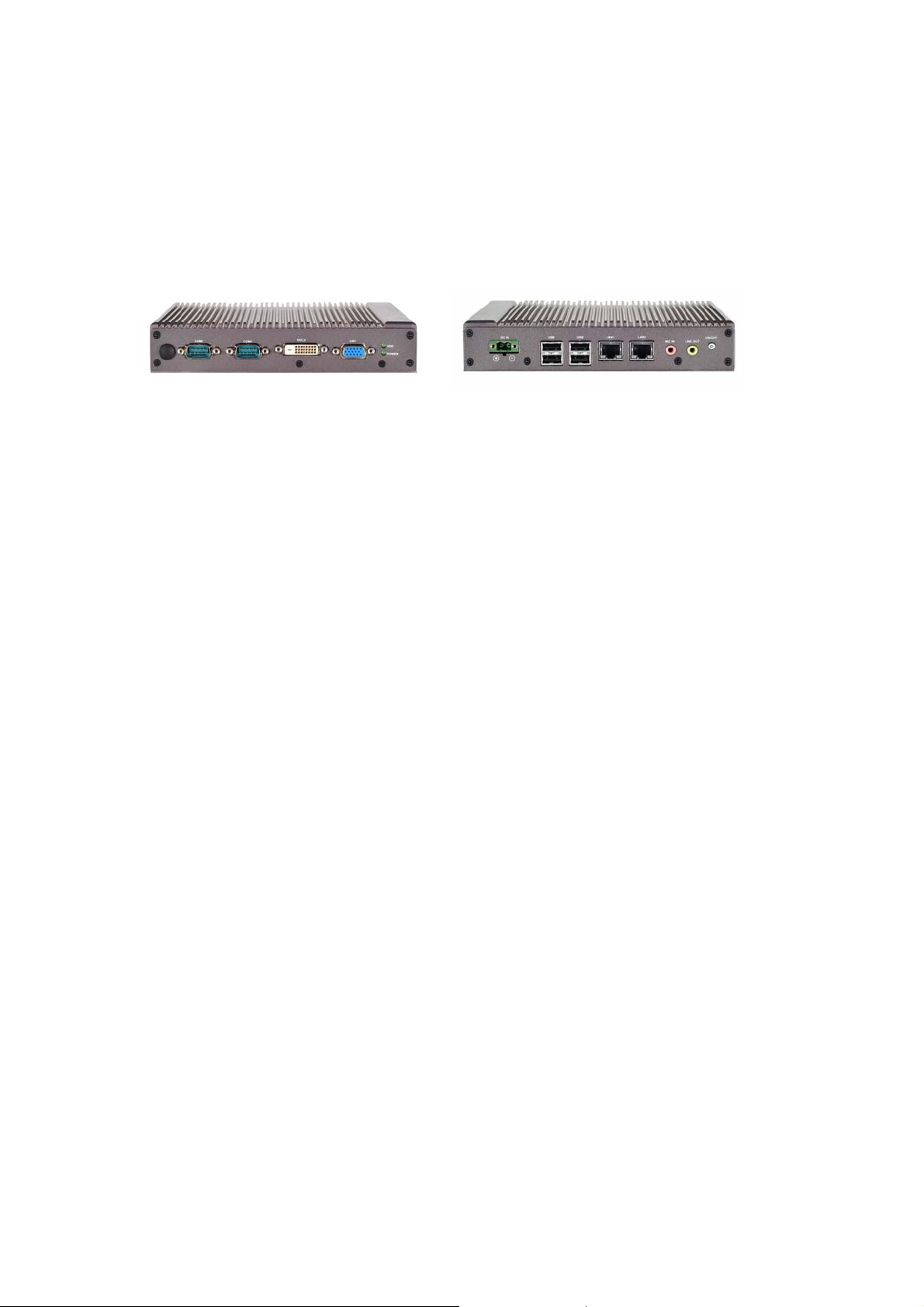
1.1 Product Introduction
Figure 1 – LEC-7000 Outlook
The LEC-7000 Fanless Embedded System built-in Intel Atom N270 (1.6Ghz CPU) onboard
and the board integrates chipsets Intel® 945GSE+ICH7M deliver lower Power consumption,
multiple I/O functions for interactive applications and various embedded computing
solutions. LEC-7000 built-in in DDR2 SO-DIMM socket for DDR2 533/667 memory, Maximum
memory capacity up to 2GB. The board also features CRT VGA Output and DVI-D VGA output
for Dual Display, Dual PCIex1 Ethernet Port one Serial ATA channels for total one Serial ATA
hard drives at maximum transfer rate up to 150MB/sec, Four USB 2.0 high speed compliant,
built-in high definition audio codec that can achieve the best stability and reliability for Digital
Signage Platform, Industrial controller applications.
1.2 Features and Benefits
z Intel® Atom™ 1.6 GHz onboard CPU
z Robust fanless enclosure
z Slim 36mm case with heat dispersing fins
z -20°C to 50°C operating temperature
z Supports up to 2GB DDR2 memory (512MB IC onboard)
z Dual Display (CRT+DVI-D)
z Dual 10/100/1000 Mbps LAN
z USB x 4, COM x 2
z Compact Flash Type I/II or SATA HDD support
z Wall or VESA mounting brackets (optional)
6
Page 7
LEC-7000 Fanless Embedded System User’s Manual
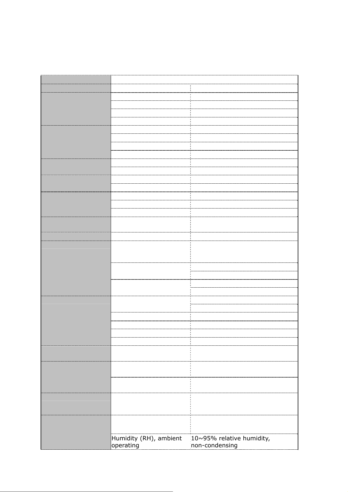
1.3 Specifications
FEATURE DESCRIPTION
Form Factor Fanless Embedded System
Platform
System Memory
Networking
Video Controller Intel 945GSE built-in Intel Extreme
Audio Codec ALC888 HD Codec
Front I/O
Rear I/O
Expansion
Hardware
Monitoring
OS Supported Linux kernel 2.4.16 or above,
Environmental
Parameters
Processor Onboard Intel® Atom™ 1.6 GHz
Chipset Intel 945GSE+ICH7M
BIOS AMIBIOS with 8Mbit BIOS Flash
FSB 533MHz
Technology DDR2 533/667
Memory On Board 512MB DDR2 onboard
Memory Socket SODIMM x 1 (up to 2GB)
Max Memory 2GB
Standard Color Grey Appearance
Construction Aluminum extrusion
Solid State CF Socket Storage
HDD 2.5” SATA HDD support
GbE (LAN) 2 (RTL8111C-VC-VR)
Wake On LAN Yes
PXE Version 2.1
COM COM1 supports RS232/422/485 with 5V
Status LEDs
USB 2.0 4
Audio Mic In / Line Out
GbE LAN 2 x RJ45
Power ATX Power Switch
Controller Winbond W83627UHGintegrated
Watchdog timer 255 level software programmable
Temperature, ambient
operating
Graphics
or 12V Power
COM2 supports RS232 Only)
DVI-D Video
VGA
Power
HDD
1 x 2 Phoenix Connector Power Input
DC Jack (optional)
Mini-PCI socket for Mini-PC Wireless
Module (Optional)
hardware monitor
watchdog timer
XPE/Win XP-32 bit, Win CE
6.0
-20°~50°C
Humidity (RH), ambient
operating
7
10~95% relative humidity,
non-condensing
Page 8
LEC-7000 Fanless Embedded System User’s Manual
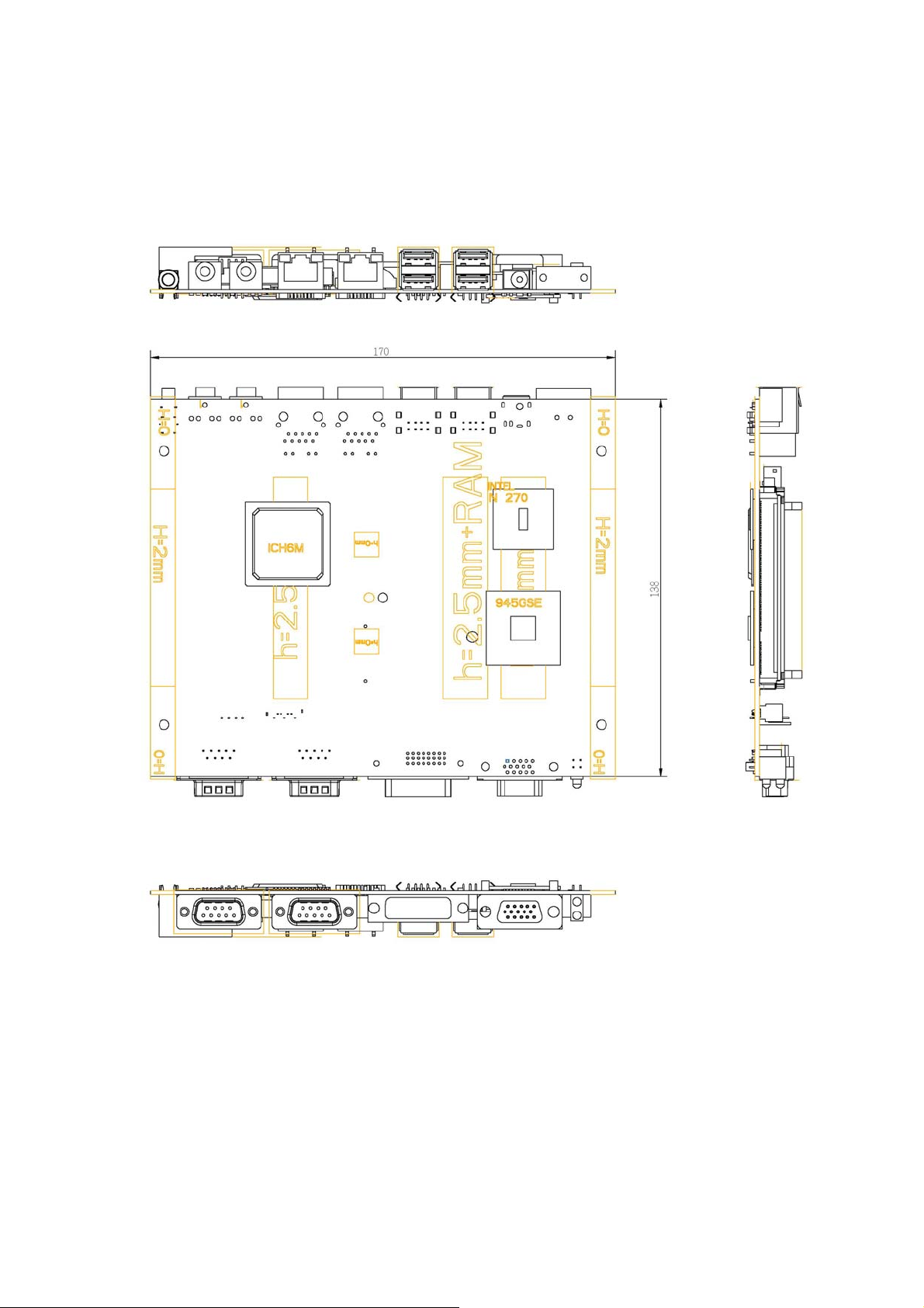
Dimensions 140D x 190W x 36H mm
Input VAC 100~240V adapter Power Supply
Output 12V DC with 60W ATX mode
power adapter
Compliance CE, FCC, RoHS
Note: All specifications and images are subject to change without notice.
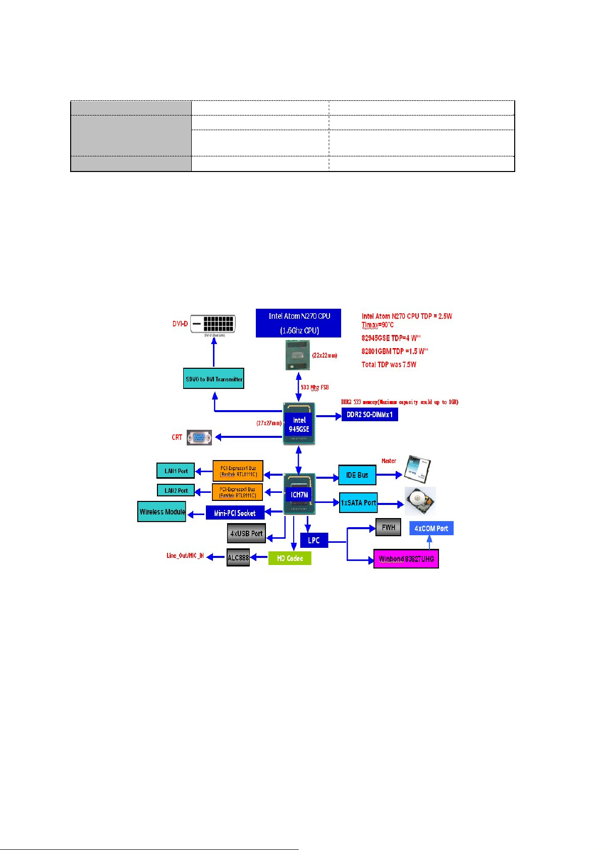
1.4 Block Diagram
Figure 2 – Block Diagram
8
Page 9

LEC-7000 Fanless Embedded System User’s Manual
1.5 Package Contents
Carefully unpack your package and make sure that you have the following items.
LEC-7000 Embedded System x 1
z DC+12V 60W Power Adapter x 1
z Power Cord x 1
z Rubber foot / Screw x 4
z E Drivers and User’s manual CDx1
Note: If you should find any components missing or damaged, please contact your dealer
immediately for assistance.
1.6 Technical Assistance
Should you have any questions or problems with your product, please contact the Lanner
sales team.
Phone: 886-2-8692-6060
Fax: 886-2-8692-6101
E-mail: sales@lannerinc.com
Prior to contacting us, we ask that you first check the electronic product documentation for
assistance. Should you still have questions, we recommend you have the following
information on hand in order to expedite the process:
1. LEC-7000 model name
2. Part number
3. Local network configuration details
4. Abnormal behavior and/or error messages reported by your network system
5. Your questions, or a description of the problem you are experiencing
9
Page 10
LEC-7000 Fanless Embedded System User’s Manual
2. System Components
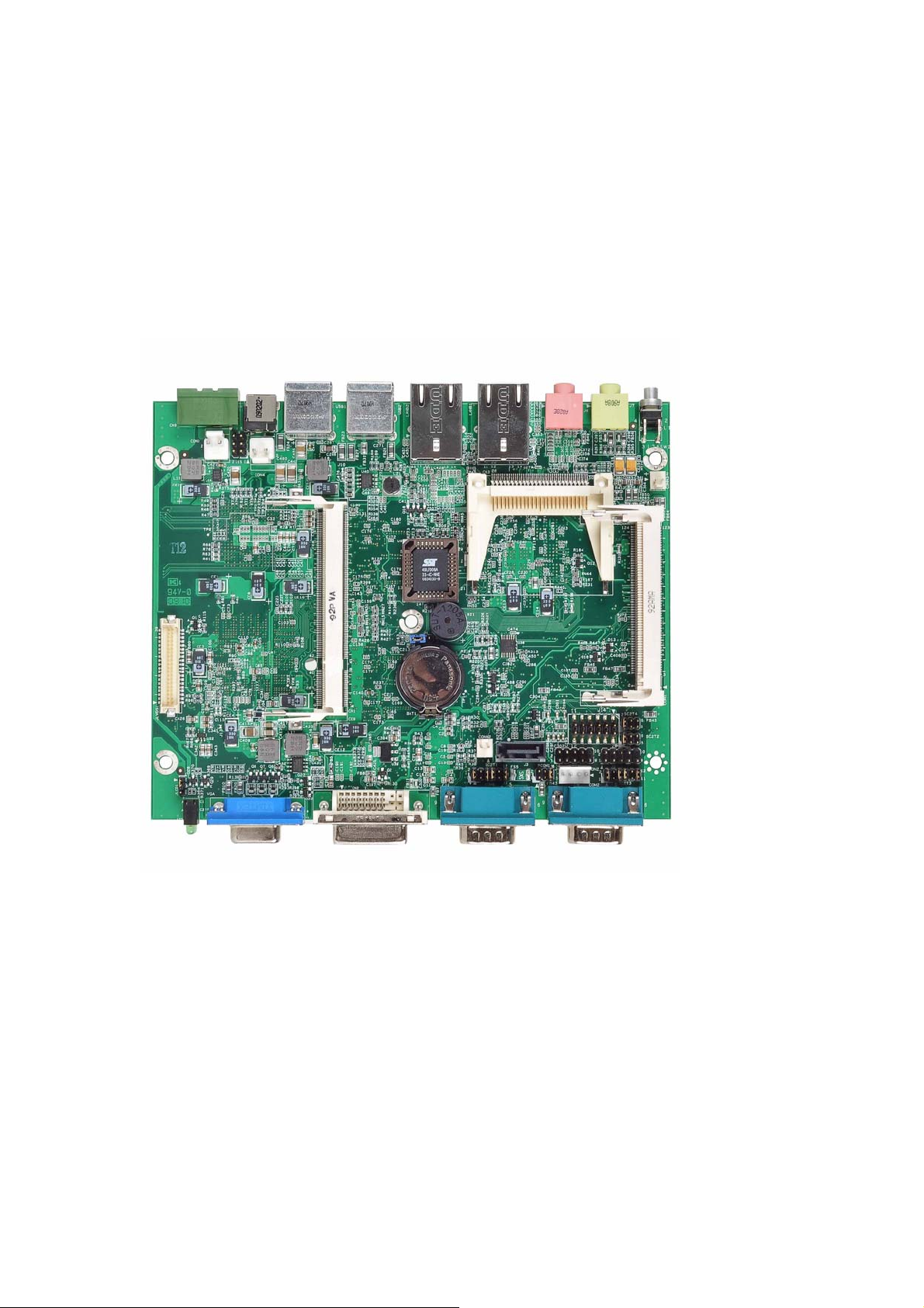
2.1 LEC-7000(VES-402) System Board
VES-402 is the system board bundled with the LEC-7000 Fanless Embedded System
platform. The succeeding sections list VES-402 related jumper settings and connector pin
assignments.
Figure 3 –VES-402 System Board
10
Page 11
LEC-7000 Fanless Embedded System User’s Manual
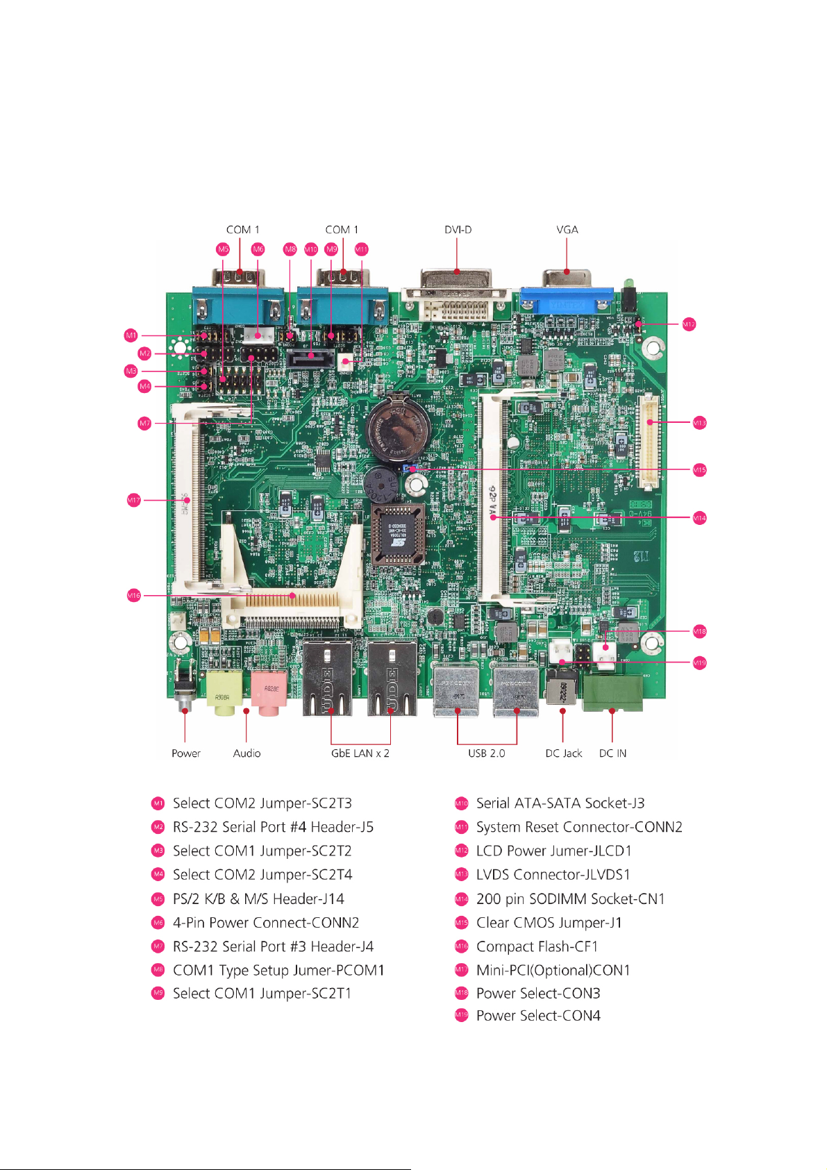
2.1.1 Board Layout
Figure 4 –VES-402 Jumpers and Connectors
11
Page 12
LEC-7000 Fanless Embedded System User’s Manual
2.1.1 Board Dimensions
Figure 5 – Board Dimension
12
Page 13

LEC-7000 Fanless Embedded System User’s Manual
2.1.2 Jumper Settings and I/O Connectors
The jumper settings and I/O connectors of the VES-402 board are specific to the LEC-2050.
Changing these settings may result in malfunctions or damages to your system.
Jumper Settings and I/O Connector Summary for VES-402:
JUMPER FUNCTION
CF1
CN1
CON1
CON2
CONN2
J1
J15
J14
Compact Flash
200 pin SODIMM Socket
Mini-PCI (Optional)
4-Pin Power Connector
System Reset Connector
Clear CMOS Jumper
POWER SELECT
PS/2 K/B & M/S Header
J3 Serial ATA-SATA Socket
J4
J5
JLCD1
JLVDS1
COM1
PCOM1
RS-232 Serial Port #3 Header
RS-232 Serial Port #4 Header
LCD Power Jumper
LVDS Connector
COM1 Pin Definition
COM1
Pin 9
Function Jumper
SC2T1 Select COM1 Jumper
SC2T2 Select COM1 Jumper
COM2 COM2 Pin Definition
SC2T3 Select COM2 Jumper
SC2T4 Select COM2 Jumper
14
Page 14
LEC-7000 Fanless Embedded System User’s Manual
2.2.1 Connector Pin Assignments
J14:2X4-Pin PS/2 Keyboard&Mouse Header(2.54mm)
PIN DESCRIPTION PIN DESCRIPTION
1 5V 2 MSCLK
3 MSDATA 4 -
5 KBDATA 6 -
7 Ground 8 KBCLK
15
Page 15

LEC-7000 Fanless Embedded System User’s Manual
COM1 Pin Definition:
PIN NO.
1
2
3
4
5 Ground (GND)
6
7
8
9
10 KEY
RS-232 RS-485 RS-422
Data Carrier
Detect (DCDA #)
Receive Data
(RXDA)
Transmit Data
(TXDA)
Data Terminal
Ready (DTRA #)
Data Set Ready
(DSRA #)
Request To Send
(RTSA #)
Clear To Send
(CTSA #)
Ring
Indicator(RIA#)
Serial Port Type
TXRX- TX-
TXRX+ TX+
RX-
RX+
SC2T1/SC2T2: Select COM1 Type Jumper
9
5
6
1
COM1
COM1 TYPE SC2T2 SC2T1
RS-232 (Default) 1-2 1-2,5-6,7-8,11-12
RS-422 3-4 2-4,3-5,6-8,9-11
RS-485 5-6 2-4,3-5,6-8,9-11
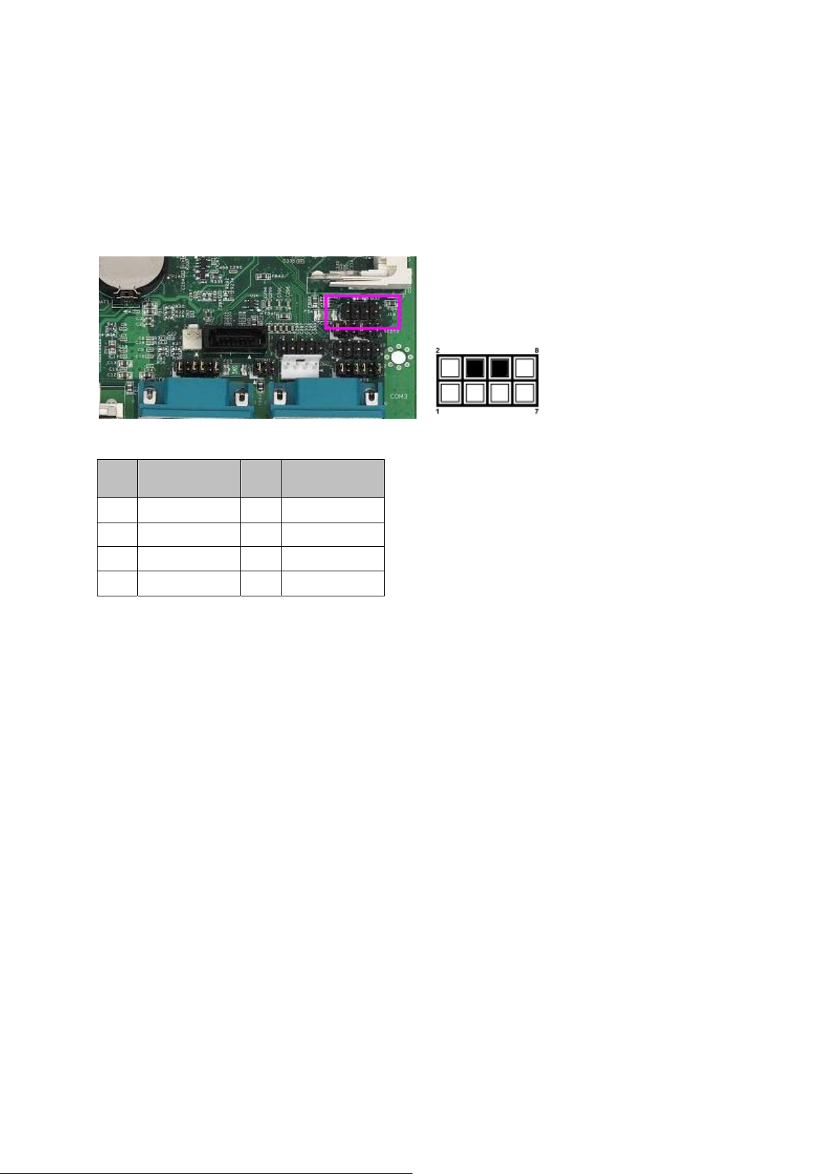
PCOM1: COM1 Pin 9 Function Jumper
The Ring Indicator (pin 9) of RS-232 port of COM1 can be altered to provide
different functions as the following:
16
Page 16

LEC-7000 Fanless Embedded System User’s Manual
PIN NO. DESCRIPTION
1-2 +5V
3-4 +12V
5-6 RI
COM2 Pin Definition:
PIN NO.
1
2
3
4
5 Ground (GND)
6
7
8
9
10 KEY
RS-232 RS-485 RS-422
Data Carrier
Detect (DCDA #)
Receive Data
(RXDA)
Transmit Data
(TXDA)
Data Terminal
Ready (DTRA #)
Data Set Ready
(DSRA #)
Request To Send
(RTSA #)
Clear To Send
(CTSA #)
Ring
Indicator(RIA#)
Serial Port Type
TXRX- TX-
TXRX+ TX+
RX-
RX+
SC2T3/SC2T4: Select COM2 Type Jumper
9 6
5
1
COM2
COM2 TYPE SC2T4 SC2T3
RS-232 (Default) 1-2 1-2,5-6,7-8,11-12
RS-422 3-4 2-4,3-5,6-8,9-11
RS-485 5-6 2-4,3-5,6-8,9-11
17
Page 17
LEC-7000 Fanless Embedded System User’s Manual
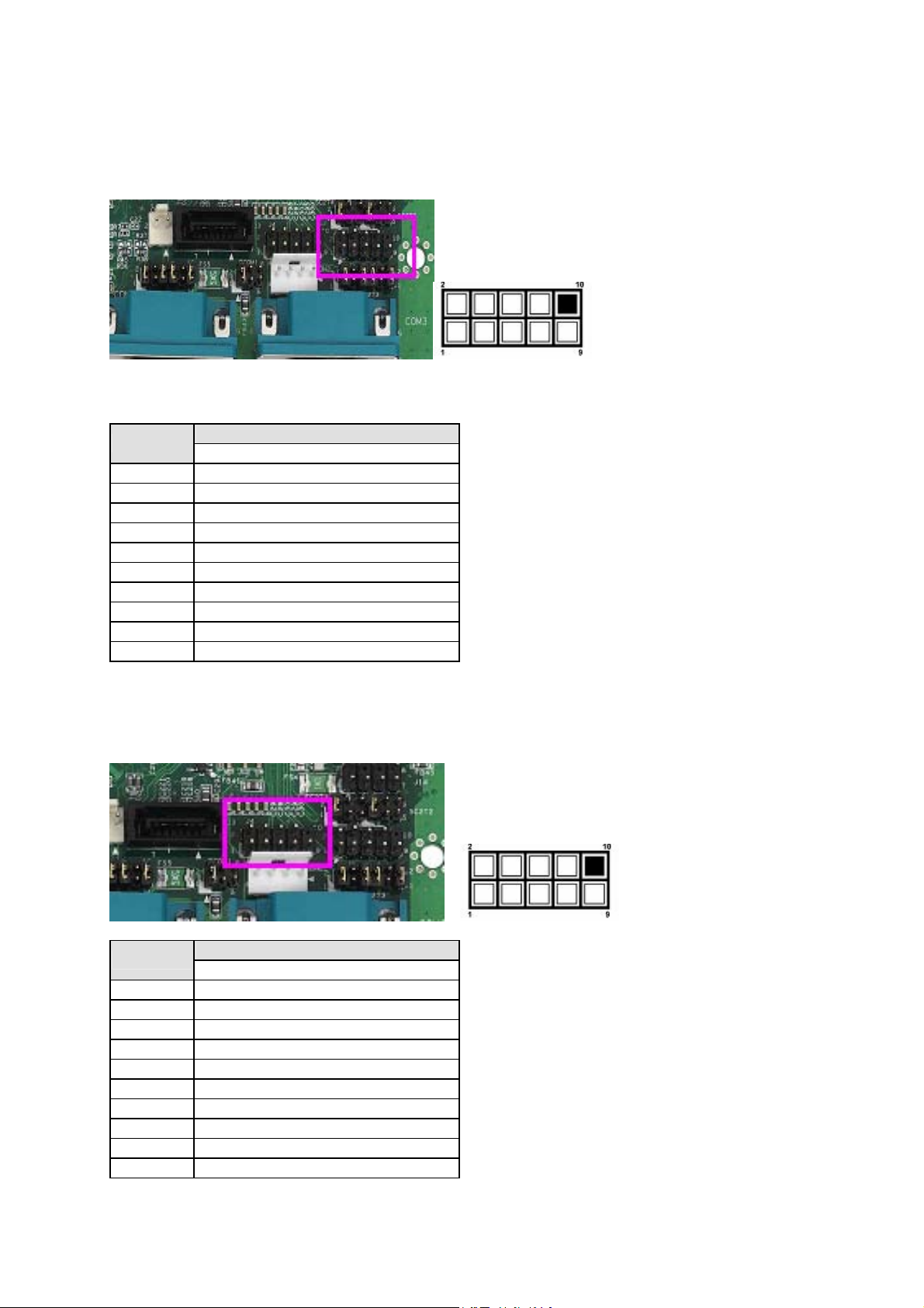
J5: RS-232 Serial Port #4 Header (2X5 Pin 2.54mm Header)
PIN NO.
1 Data Carrier Detect (DCDB #)
2 Data Set Ready (DSRB #)
3 Receive Data (RXDB)
4 Request To Send (RTSB #)
5 Transmit Data (TXDB)
6 Clear To Send (CTSB #)
7 Data Terminal Ready (DTRB #)
8 Ring Indicator (RIB #)
9 Ground
10 KEY
DESCRIPTION
RS-232
J4: RS-232 Serial Port #3 Header (2X5 Pin 2.54mm Header)
PIN NO.
1 Data Carrier Detect (DCDB #)
2 Data Set Ready (DSRB #)
3 Receive Data (RXDB)
4 Request To Send (RTSB #)
5 Transmit Data (TXDB)
6 Clear To Send (CTSB #)
7 Data Terminal Ready (DTRB #)
8 Ring Indicator (RIB #)
9 Ground
10 KEY
DESCRIPTION
RS-232
16
Page 18

LEC-7000 Fanless Embedded System User’s Manual
CON2: 4-Pin Power Connector (4P Male )
Pin No. Description
1 +12V
2 GND
3 GND
4 +5V
CONN2: System Reset Connector
J1: Clear CMOS Jumper
Description CMOS1
Normal (Default) 1-2
Clear CMOS 2-3
17
Page 19

LEC-7000 Fanless Embedded System User’s Manual
JLCD1: LCD Power Jumper
Description CMOS1
3.3V(Default) 1-2
5V 2-3
JLVDS1: LVDS Connector (2x20 1.25mm Connector)
Pin
No. Description
1 PVDD 2 12V 3 LCD1D0# 4 LCD1D4#
5 LCD1D0 6 LCD1D4 7 PVDD 8 12V
9 LCD1D1# 10 LCD1D5# 11 LCD1D1 12 LCD1D5
13 GND 14 GND 15 LCD1D2# 16 LCD1D6#
17 LCD1D2 18 LCD1D6 19 GND 20 GND
21 LCD1D3# 22 LCD1D7# 23 LCD1D3 24 LCD1D7
25 LCLK1# 26 LCLK2# 27 LCLK1 28 LCLK2
29 ENBLD1 30 BLCON 31 GND 32 GND
33 ENBLD2 34 BLCON2 35 PVDD2 36 GND
37 PVDD2 38 SPD1 39 GND 40 SPCLK1
Pin
No. Description
Pin
No. Description
Pin
No. Description
18
Page 20

LEC-7000 Fanless Embedded System User’s Manual
2.2 LEC-7000 Embedded System Mechanisms
This section of the manual describes the mechanical and device nomenclature of the
LEC-7000.
2.2.1 Front View
Figure 6 – LEC-7000 Front View
19
Page 21

LEC-7000 Fanless Embedded System User’s Manual
2.2.2 Rear View
Figure 7 – LEC-7000 Rear View
20
Page 22

LEC-7000 Fanless Embedded System User’s Manual
3. Hardware Installation Guide
3.1 LEC-7000 Embedded System
Figure 8 – LEC-7000 Embedded System Outlook
3.1.1 Begin Installation
Unscrew 10 thumbscrews of the chassis bottom cover and than remove the chassis bottom cover.
Note: For Safety reasons, please ensure that the power cord is disconnected
before opening the case.
21
Page 23

LEC-7000 Fanless Embedded System User’s Manual
3.1.2 System Memory Installation
Install the memory module into the socket and push it firmly down until it is fully seated.
3.1.3 CompactFlash Card Installation
Carefully insert the CompactFlash card into the slot as shown in the illustration above.
22
Page 24

LEC-7000 Fanless Embedded System User’s Manual
3.1.4 HDD Installation
1. Place the HDD (upside down) in the rack of bottom.
Note: Please install 2.5” HDD
2. Secure with 4 screws from the side
23
Page 25

LEC-7000 Fanless Embedded System User’s Manual
3. Connect the Serial ATA/Power Cable to the HDD
4. Plug the Serial ATA cable to the SATA Connector (J3)
24
Page 26

LEC-7000 Fanless Embedded System User’s Manual
5. Plug the Power cable to the 4-Pin Power Connector (CON2)
3.1.5 System Complete
1. Replace the cover
25
Page 27

LEC-7000 Fanless Embedded System User’s Manual
2. Refasten the thumbscrews and than LEC-7000 Embedded System Installation Complete
Note: Please load the optimized BIOS values.
3.2 Mounting Kits
3.2.1 Wall Mount (Optional)
Figure 9 – Wall Mount View
26
Page 28

LEC-7000 Fanless Embedded System User’s Manual
3.2.2 VESA Mount (Optional)
Figure 10 – Wall Mount View
3.2.3 Rack Mount Kit (Optional)
Figure 11 – Rack Mount View
27
Page 29

LEC-7000 Fanless Embedded System User’s Manual
A. Appendix A: LAN Port LED Indicators
LED/ Color Status Description
Green Off LAN is link to a 10 Mbps device.
Yellow Blinks LAN port is receiving and transmitting packets.
Green On LAN is link to a 10 or 100Mbps device.
Yellow Blinks LAN port is receiving and transmitting packets.
Orange On LAN is link to a 1G bps device.
Yellow Blinks LAN port is receiving and transmitting packets.
28
Page 30

LEC-7000 Fanless Embedded System User’s Manual
B. Appendix B: Watchdog Timer
B.1 Most Introduction
systems need to be self-reliant. If an error should occur it is typically not possible to wait for
the system to be rebooted manually. In some cases, such as space probes, the system is
simply not accessible to human operators. If such systems should ever hang, they would be
permanently disabled. In other cases, the speed at which a human operator would reset the
system would be too slow to meet the uptime requirements of the product.
A watchdog timer is a piece of hardware that can be used to automatically detect system
anomalies and reset the processor in the case any problems are found. Generally speaking,
a watchdog timer is based on a counter that counts down from an initial value to zero. The
software selects the counter's initial value and periodically restarts it. Should the counter
reach zero before the software restarts it, the software is presumed to be malfunctioning,
and the processor's reset signal is asserted. Thus, the processor will be restarted as if a
human operator had cycled the power.
B.2 Detail Register Descriptions
A watchdog action consists of a series of watchdog instructions. A watchdog instruction is
the operation on a register region. This section describes the detail register in LPD I/O
(W83697HG)
B.2.1 To used the watch-dog timer
For DOS system:
Execute the EM9765WD1.EXE file under DOS, then key-in 0~255. The system will reboot
automatically according to the time-out you set.
29
Page 31

C. Appendix C: Simple Testing
Procedures of RS-232/RS-485
Connections
This section illustrates a simple method to test your Serial port’s connection and
data communication.
Let’s use COM2 port with a configuration of RS-485 as an example. To configure
the serial type of COM2, refer to SC2T3/SC2T4: Select COM2 Type Jumper,
Section 2.2.1 Connector Pin Assignments.
1. Enter to BIOS setup utility of the LEC-2050 and make sure that the serial port 2’s base
address is: 2F8.
2. You can connect to the LEC-2050 serial device server’s COM2 serial port with a
RS-232 (DB-9 female) communication cable, with the other end connecting to
the host’s serial port.
3. Install PComm Lift software on the host PC and LEC-2050 to be your testing
terminal.
4. Start the PComm Terminal Emulator from your desktop.
Page 32

5. Select Port Manager on the main menu.
6. Configure the COM port as the following: select port to be COM2, Baud Rate to
be 9600, Data Bit to be 8, Parity to be None, and Stop Bits to be1.
Page 33

7. Click RTS to start sending messages from the host to LEC-2050.
8. Click DTR to start receiving messages from LEC-2050 on the host. Remember
to send messages from the LEC-2050’s terminal before receiving messages on
the host.
Page 34

9. To configure the message encoding method, select Port Manager from the
menu bar of the PComm. Select Send Pattern and then select ASCII or HEX
from the Data Pattern option menu. Enter letters from A to Z if you select ASCII
or enter 0-9 and A-F if you select HEX.
10. If you select ASCII to be the encoding method as shown in the example, you
should see the text messages showing on the receiving end.
Page 35

Page 36

LEC-7000 Fanless Embedded System User’s Manual
Terms and Conditions
Date:2007.03.19
Warranty Policy
1. All products are under warranty against defects in materials and workmanship for a
period of one year from the date of purchase.
The buyer will bear the return freight charges for goods returned for repair within the
2.
warranty period; whereas the manufacturer will bear the after service freight charges for
goods returned to the user.
3. The buyer will pay for repair (for replaced components plus service time) and
transportation charges (both ways) for items after the expiration of the warranty period.
4. If the RMA Service Request Form does not meet the stated requirement as listed on “RMA
Service,” RMA goods will be returned at customer’s expense.
The following conditions are excluded from this warranty:
5.
Improper or inadequate maintenance by the customer
Unauthorized modification, misuse, or reversed engineering of the product
Operation outside of the environmental specifications for the product.
RMA Service
Requesting a RMA#
1. To obtain a RMA number, simply fill out and fax the “RMA Request Form” to your
supplier.
2. The customer is required to fill out the problem code as listed. If your problem is
not among the codes listed, please write the symptom description in the remarks box.
3. Ship the defective unit(s) on freight prepaid terms. Use the original packing
materials when possible.
4. Mark the RMA# clearly on the box.
Note: Customer is responsible for shipping damage(s) resulting from inadequate/loose packing of the
defective unit(s). All RMA# are valid for 30 days only; RMA goods received after the effective RMA#
period will be rejected.
30
Page 37

LEC-7000 Fanless Embedded System User’s Manual
RMA Service Request Form
When requesting RMA service, please fill out the following form. Without this form enclosed,
your RMA cannot be processed.
RMA No:
Company: Contact Person:
Phone No. Purchased Date:
Fax No.: Applied Date:
Return Shipping Address:
Shipping by: □ Air Freight □ Sea □ Express ___
□ Others:________________
Item Model Name Serial Number Configuration
Item Problem Code Failure Status
Reasons to Return: □ Repair(Please include failure details)
□ Testing Purpose
*Problem Code:
01:D.O.A.
02: Second Time
R.M.A.
03: CMOS Data Lost
04: FDC Fail
05: HDC Fail
06: Bad Slot
Request Party
Authorized Signature / Date Authorized Signature / Date
07: BIOS Problem
08: Keyboard Controller Fail
09: Cache RMA Problem
10: Memory Socket Bad
11: Hang Up Software
12: Out Look Damage
13: SCSI
14: LPT Port
15: PS2
16: LAN
17: COM Port
18: Watchdog Timer
Confirmed By Supplier
19: DIO
20: Buzzer
21: Shut Down
22: Panel Fail
23: CRT Fail
24: Others (Pls specify)
31
 Loading...