

Page 1

Industrial
Communications
Hardware Platforms for Industrial Computing
LEC-6040
V1.1
User's Manual
Release Date: 2015-09-09
Page 2
Overview
Icon Descriptions
The icons are used in the manual to serve as an
indication of interest topics or important messages.
Below is a description of these icons:
NOTE: This check mark indicates
that there is a note of interest and is
something that you should pay special
attention to while using the product.
WARNING: This exclamation point
indicates that there is a caution or
warning and it is something that could
damage your property or product.
Online Resources
The listed websites are links to the on-line product
information and technical support.
Resource Website
Lanner http://www.lannerinc.com
Product Resources
http://www.lannerinc.com/support/
download-center
RMA http://eRMA.lannerinc.com
Copyright and Trademarks
This document is copyrighted, © 2014. All rights are
reserved. The original manufacturer reserves the right to
make improvements to the products described in this
manual at any time without notice.
No part of this manual may be reproduced, copied,
translated or transmitted in any form or by any means
without the prior written permission of the original
manufacturer. Information provided in this manual
is intended to be accurate and reliable. However, the
original manufacturer assumes no responsibility for its
use, nor for any infringements upon the rights of third
parties that may result from such use.
Acknowledgement
Intel, Pentium and Celeron are registered trademarks of
Intel Corp.
Microsoft Windows and MS-DOS are registered
trademarks of Microsoft Corp.
All other product names or trademarks are properties of
their respective owners.
Compliances and Certification
CE Certication
This product has passed the CE test for environmental
specifications. Test conditions for passing included
the equipment being operated within an industrial
enclosure. In order to protect the product from being
damaged by ESD (Electrostatic Discharge) and EMI
leakage, we strongly recommend the use of CEcompliant industrial enclosure products.
FCC Class A Certication
This equipment has been tested and found to comply
with the limits for a Class A digital device, pursuant
to Part 15 of the FCC Rules. These limits are designed
to provide reasonable protection against harmful
interference when the equipment is operated in a
commercial environment. This equipment generates,
uses and can radiate radio frequency energy and, if not
installed and used in accordance with the instruction
manual, may cause harmful interference to radio
communications. Operation of this equipment in a
residential area is likely to cause harmful interference
in which case the user will be required to correct the
interference at his own expense.
Page 3
EMC Notice
This equipment has been tested and found to comply
with the limits for a Class A digital device, pursuant to Part
15 of the FCC Rules. These limits are designed to provide
reasonable protection against harmful interference when
the equipment is operated in a commercial environment.
This equipment generates, uses, and can radiate radio
frequency energy and, if not installed and used in
accordance with the instruction manual, may cause
harmful interference to radio communications. Operation
of this equipment in a residential area is likely to cause
harmful interference in which case users will be required
to correct the interference at their own expense.
Safety Guidelines
Follow these guidelines to ensure general safety:
Keep the chassis area clear and dust-free before, •
during and after installation.
Do not wear loose clothing or jewelry that could get •
caught in the chassis. Fasten your tie or scarf and roll
up your sleeves.
Wear safety glasses/goggles if you are working •
under any conditions that might be hazardous to
your eyes.
Do not perform any action that creates a potential •
hazard to people or makes the equipment unsafe.
Disconnect all power by turning off the power and •
unplugging the power cord before installing or
removing a chassis or working near power supplies
Do not work alone if potentially hazardous •
conditions exist.
Never assume that power is disconnected from a •
circuit; always check the circuit.
LITHIUM BATTERY CAUTION:
Risk of explosion could occur if battery is replaced by an
incorrect type. Please dispose of used batteries according
to the recycling instructions of your country.
Installation only by a trained electrician or only by an •
electrically trained person who knows all the applied
or related installation and device specifications..
Do not carry the handle of power supplies when •
moving to other place.
The machine can only be used in a fixed location •
such as labs or computer facilities.
Operating Safety
Electrical eq u i p m e nt ge nerat es he at. Am b i e n t ai r •
temperature may not be adequate to cool equipment to
acceptable operating temperatures without adequate
circulation. Be sure that the room in which you choose to
operate your system has adequate air circulation.
Ensure that the chassis cover is secure. The chassis design •
allows cooling air to circulate effectively. An open chassis
permits air leaks, which may interrupt and redirect the flow
of cooling air from internal components.
Electrostatic discharge (ESD) can damage equipment and
impair electrical circuitry. ESD damage occurs when electronic
components are improperly handled and can result in complete
or intermittent failures. Be sure to follow ESD-prevention
procedures when removing and replacing components to avoid
these problems.
Wear an ESD-preventive wrist strap, ensuring that it makes •
good skin contact. If no wrist strap is available, ground
yourself by touching the metal part of the chassis.
Periodically check the resistance value of the antistatic •
stra p, which sho uld be betwee n 1 and 10 megohms
(Mohms).
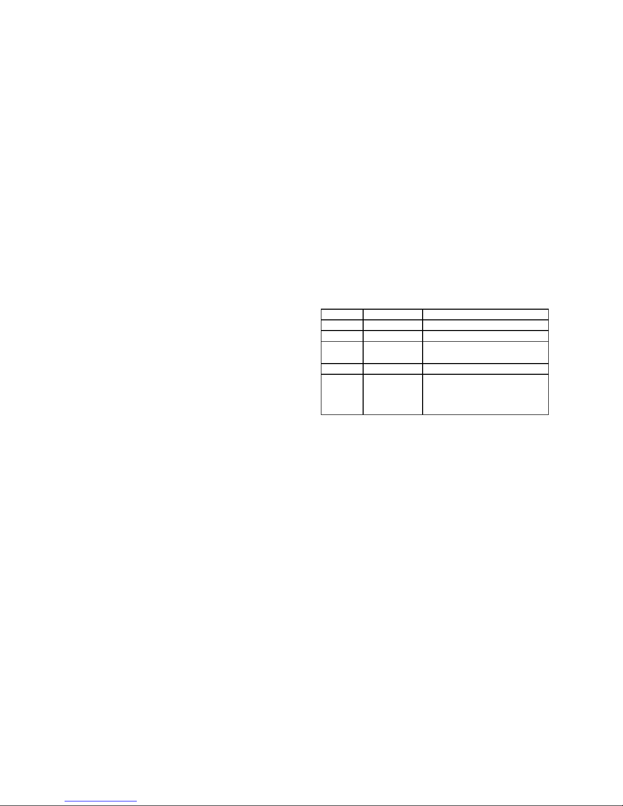
Version Date (Y/M/D) Description
0.1 2014/11/07 Preliminary
0.2 2014/11/12 Added hardware setup
0.3 2014/11/21 Revised pin assignments and
specifications
1.0 2015/06/29 Official release
1.1 2015/09/09 Removed CompactFlash
Added mSATA signal to miniPCIe socket2
Page 4

Table of Contents
Chapter 1: Introduction 5
System Specifications 5
Package Contents 6
Ordering Information 6
Mechanical Specifications 7
Chapter 2: System 8
Front Panel 8
Rear Panel 9
Block Diagram 10
Chapter 3: Motherboard Information 11
Inside LEC-6040 11
Motherboard Layout 12
Add-on Card and Backplane 14
Motherboard Jumper and Connector Table 15
Jumper Setting & Connector Pinouts 16
Chapter 4: Hardware Setup 20
Preparing the Hardware Installation 20
Installing the System Memory 20
Installing a Disk Drive (HDD/SSD) 21
Connecting Power 22
Mounting LEC-6040M by DIN Rail 23
Installing the Ear Mount Brackets 23
Installing the Wall Mount Brackets 24
Appendix 1: Programming Watchdog Timer 25
Appendix 2: Terms and Conditions 26
Page 5
Chapter 1: Introduction
Brief
Thank you for choosing LEC-6040. LEC-6040 is an
IEC-61850-3 certied fanless industrial box PC with
high-performance Intel® Haswell Core™ i5-4402E or
i3-4102E CPU, installable through DIN rail, wall-mount,
or as desktop. Its serial COM port and Ethernet ports
are strengthened with surge/ESD protection to ensure
operational safety. LEC-6040 continues Lanner’s well-
established traditions of fanless design, wide ambient
temperature operation, and reliability. For extended
functionality, LEC-6040 offers multiple functional
expansions for storage, communication and display
purposes.
Here is the summary of the key features of LEC-6040:
Intel® Haswell Core™ inside for high performance
The internal 4th generation Intel® CPU in Haswell •
22nm microarchitecture delivers ultra graphical and
media performance as well as advanced security
instructions, ideal for industrial applications.
Enhanced Protection for Serial COM and Ethernet
ports
LEC-6040 serial COM port and Ethernet ports are •
isolated and engineered with ESD/surge protection
to reinforce communication reliability.
Expansion Capability
LEC-6040 offers functional expansions, including 2 •
x external USB 3.0 ports, 1 x internal USB 2.0 port, 1
x internal pin header for display purpose, 1 x SATA
port, 1 x full-sized mini PCIe slot, 1 x half-sized mini
PCIe slot (or mSATA Mini), and optionally 8 x COM
ports.
Fanless & Wide Temperature
The fanless design allows external environmental •
tolerance and avoids mechanical failure. In addition,
LEC-6040 is able to operate in wide ambient
temperature from -20°C to 55°C
Flexible I/O Design
LEC-6040 series provides various I/O configurations •
such as 4 x GbE LAN ports, 6 x GbE + 2 Fiber SFP
ports or 8 x GbE LAN ports.
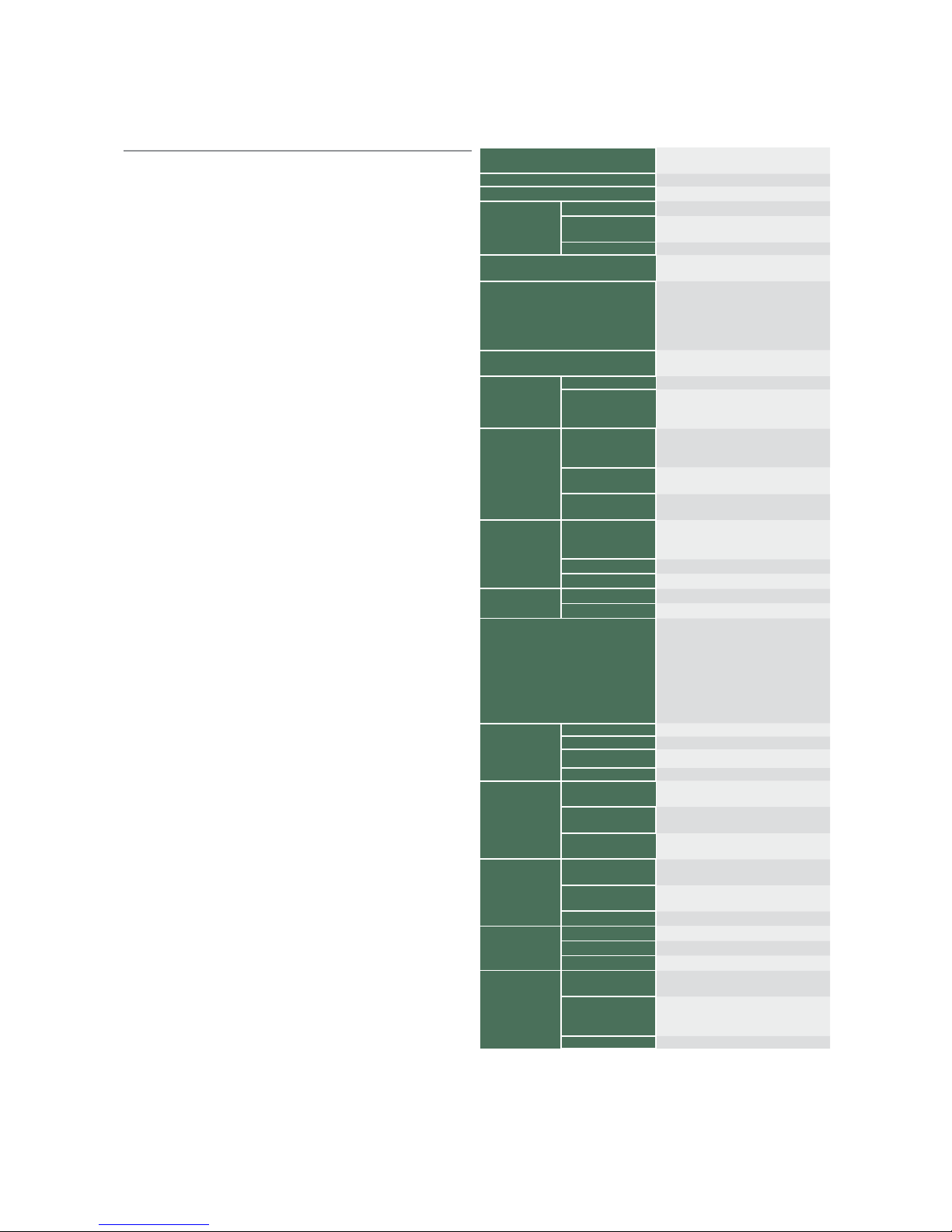
System Specifications
Processor Options
Intel® Core™ i3-4102E or Core™
i5-4402E
Chipset Intel® QM87
BIOS AMI SPI Flash ROM
System
Memory
Sockets 1 x 204-pin DDR3L SO-DIMM socket
Technology
DDR3L 1333/1600 MHz, unbuffered,
Non-ECC, low-voltage
Max. Capacity 8 GB
USB
2 x external USB 3.0 ports
1 x internal USB 2.0 port
Expansion Bus
1 x full-sized mini PCIe socket for
WWAN module (for PCI Express & USB
& SIM card)
1 x half-sized mini PCIe, support WLAN
module (for USB) or mSATA storage
OS Support
Microsoft Windows 7 Embedded,
Window 7, Linux 2.6
Storage
NAND Flash N/A
HDD/SSD Support
1 x SATA 2.5” HDD/SSD
1 x mSATA storage (leveraged from the
mini-PCIe2 socket)
Networking
LAN
4/6/8 x RJ45 for 10/100/1000 Mbps
Ethernet ports
2 x Gigabit SFP ports (B2 type only)
Controller
Intel® I210 Gigabit Ethernet Controller
(I210 x 4)
Magnetic Isolation
Protection
1.5 KV built-in
Serial Interface
Serial Standard
1x DB9 supports software RS-232 (3
pin: RxD,TxD,GND) with Isolation and
Protection
ESD Protection 15 KV for all signals
Baudrate Supports 50 bps to 115.2 kbps
Display
Graphics Controller Intel® HD 4600
Display Interface Internal pinheader
LEDs
LED connector for
1x Power on for LED in Green
1x Storage access LED in Yellow
16x double stack LED for Ethernet
active/link status
1 x COM for LED in Yellow/Green
4x double stack LED for Programmable
(Green)
Physical
Characteristics
Housing Steel Aluminium
Weight 2.5 kg
Dimensions(HxWxD) 68 x 210 x 190, unit: mm
Mounting Options DIN rail and wall mount
Environment
Operating
Temperature
-20~55°C
Storage Temperature -40~80°C
Ambient Relative
Humidity
5 to 95% (non-condensing)
Power
Input Voltage
Single 12Vdc power input w/ 2xpin
Phoenix Contact connector
Power Consumption 27W
Connector 2-pin terminal block
Standard and
Regulation
EMC CE, FCC
Green product RoHS
Others IEC-61850-3 Compliance
Reliability
Alter tool
Built-in buzzer and RTC (real-time
clock) with lithium battery backup
Automatic Reboot
Trigger
Watchdog Timer 1~255 level time
interval system reset, software program-
mable
Warranty 2 years
Page 6

Package Contents
Your package contains the following items:
LEC-6040 fanless box PC •
Drivers and User’s Manual CD •
Notes: if there is any missing item, please contact your dealer immediately for assistance.
Ordering Information
LEC-6040H-B1
Intel® Core™ Core™ i5-4402E 2.7 GHz CPU, 4 x Intel®
GbE, 1 x DB9, 2 x USB, 2 x Mini-PCIe, 1x SATA, Single
12V DC w/ 2-Pin terminal block, DIN rail
LEC-6040H-B2
Intel® Core™ i5-4402E 2.7 GHz CPU, 6 x Intel® GbE+2 x
SFP, 1 x DB9, 2 x USB, 2 x Mini-PCIe, 1x SATA, Single 12V
DC w/ 2-Pin terminal block, DIN rail
LEC-6040H-B3
Intel® Core™ i5-4402E 2.7 GHz CPU, 8 x Intel® GbE, 1 x
DB9, 2 x USB, 2 x Mini-PCIe, 1x SATA, Single 12V DC w/
2-Pin terminal block, DIN rail
LEC-6040M-B1
Intel® Core™ i3-4102E 1.60 GHz CPU, 4 x Intel® GbE, 1
x DB9, 2 x USB, 2 x Mini-PCIe, 1x SATA, Single 12Vdc w/
2-pin terminal block, DIN-Rail
LEC-6040M-B2
Intel® Core™ i3-4102E 1.60 GHz CPU, 6 x Intel® GbE+
2 x SFP, 1 x DB9, 2 x USB, 2 x Mini-PCIe, 1x SATA, Single
12Vdc w/ 2-pin terminal block, DIN rail
LEC-6040M-B3
Intel® Core™ i3-4102E 1.60 GHz CPU, 8 x Intel® GbE, 1
x DB9, 2 x USB, 2 x Mini-PCIe, 1x SATA, Single 12Vdc w/
2-pin terminal block, DIN rail
Page 7
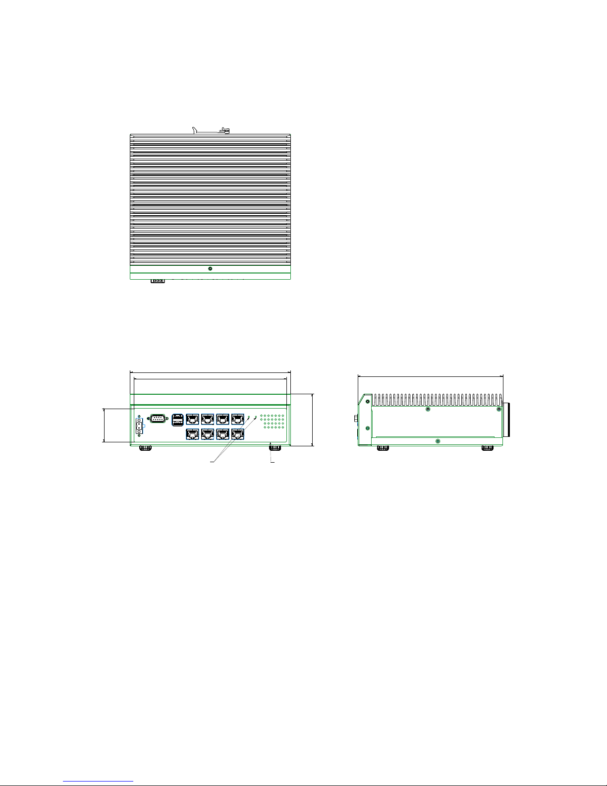
Mechanical Specifications (based on 8 x
GbE ports model)
210
68
43.82
200
190
button holes
SINK 0.4mm FOR NAME PLATE PASTED
9 10 11 12
13 14 15 16
Unit: mm
Page 8
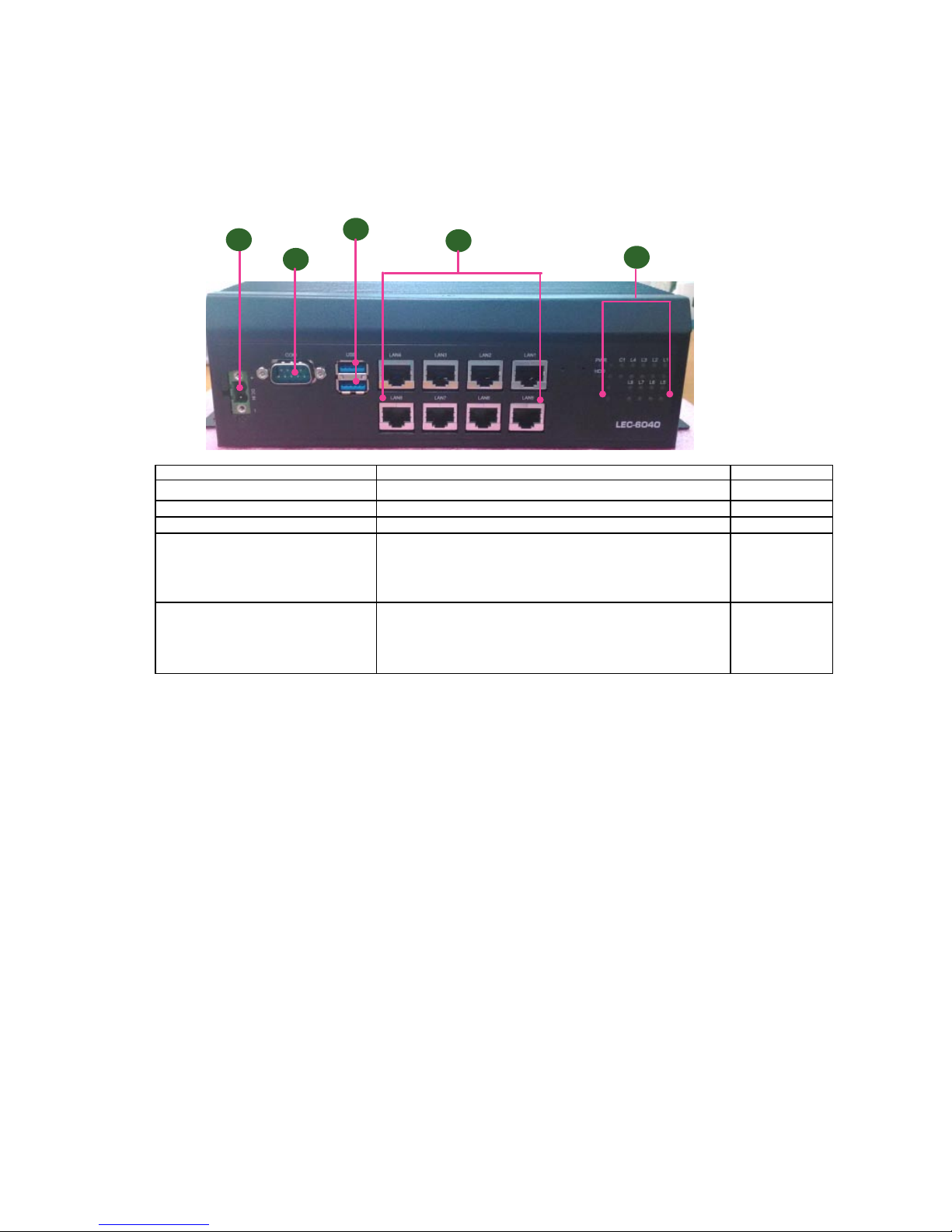
Front Panel (B1/B3 Types)
I/O Description Note
F1 DC IN
Single 12VDC Power input
F2 COM ports
1 x DB9 RS-232 COM ports; COM1 with isolated protection
F3 USB 3.0 ports 2 x USB 3.0 Type-A ports
F4 LAN 4 or 8 x RJ-45 LAN ports at 10/100/1000 Mbps depending
on the model chosen
4 x RJ-45 LAN for B1 type model•
8 x RJ-45 LAN for B3 type model•
This image is based
on the 8-LAN port
model
F5 Status LED 1x Power on for LED in Green
1x HDD/SSD storage access LED in Yellow
16 x double stack LED for Ethernet active/link status
1 x COM for LED in Yellow/Green
F1
F2
F3
F4
F5
Page 9
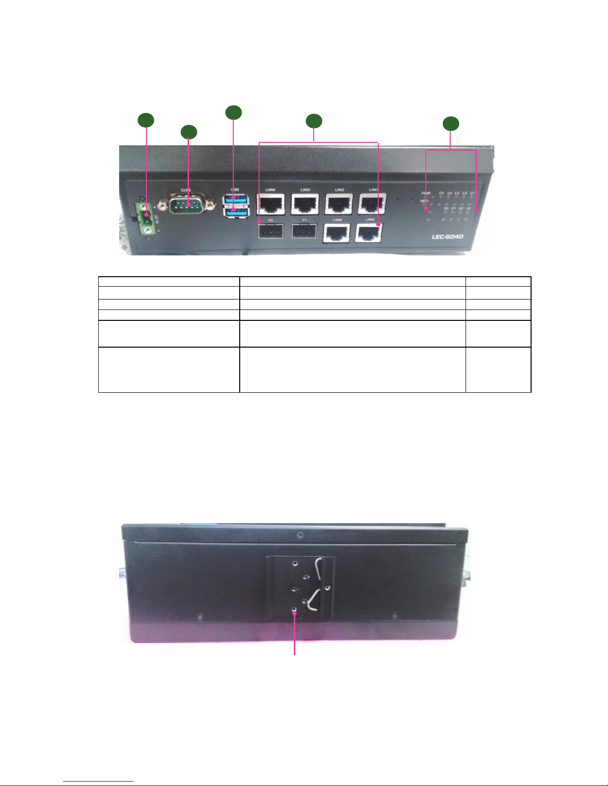
DIN Rail mounting use
Rear Panel (B1/B2/B3 Types)
Front Panel (B2 Type)
I/O Description Note
F1 DC IN
Single 12VDC Power input
F2 COM ports
1 x DB9 RS-232 COM ports; COM1 with isolated protection
F3 USB 3.0 ports 2 x USB 3.0 Type-A ports
F4 LAN 6 x RJ-45 LAN ports at 10/100/1000 Mbps depending
2 x SFP ports
This image is based
on the 8-LAN port
model
F5 Status LED 1x Power on for LED in Green
1x HDD/SSD storage access LED in Yellow
16 x double stack LED for Ethernet active/link status
1 x COM for LED in Yellow/Green
F1
F2
F3
F4
F5
Page 10
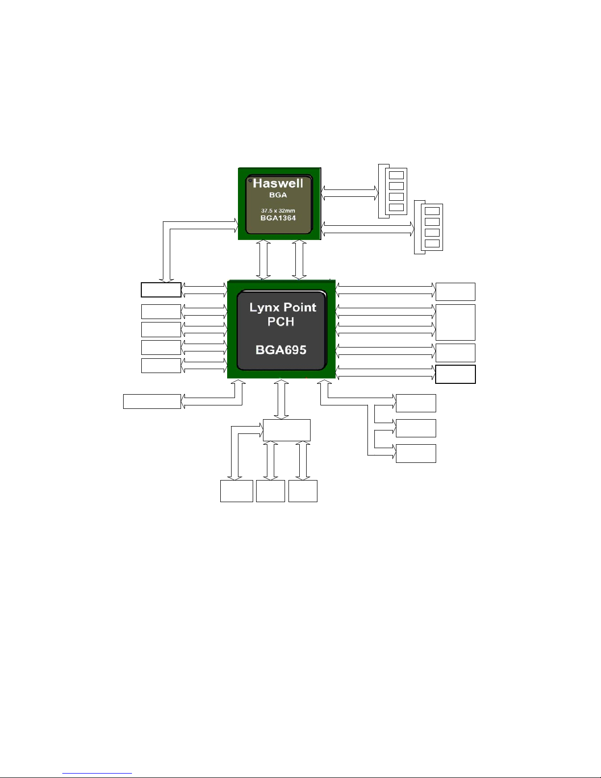
Block Diagram
B
C
D
E
x4 DMIx2 FDI
DDR3 ChA
DDR3 ChB
i5 4400E
CL8064701483902
PCH QM87
DH82QM87
Super I/O
F81801
COM1
LPC
USB 2.0 x2
USB 3.0 x2
USB
2.0/3.0
Connector
USB 2.0
PIN HEADER
USB 2.0 x2
LAN1 i210AT
LAN2 i210AT
LAN3 i210AT
LAN4 i210AT
PCIE x1
PCIE x1
PCIE x1
PCIE x1
PCIE x4PCIe X8 SLOT
K.B/Mouse COM2
VGA
PIN HEADER
VGA
PCIE x1
USB 2.0 x1
Full size
Mini-PCIe
SATA0
SATA TO CF
SATA conn.
SATA conn.
SATA4
SATA5
SATA
USB 2.0 x1 Half size
Mini-PCIe
Page 11
Chapter 3: Motherboard
Information
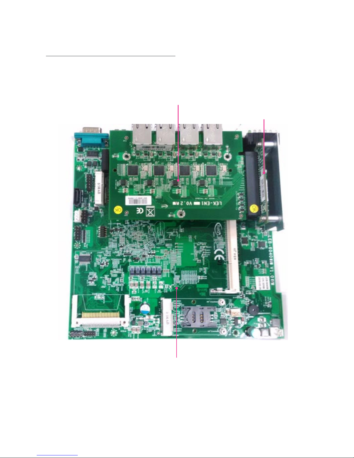
Inside LEC-6040
Motherboard LEB-6040B
Add-on Card LEK-EN1
Backplane LEK-P02
LEB-6040B: the motherboard
LEK-EN1: the add-on card for additional LAN ports. It comes in either 2 LAN ports or 4 LAN ports type. The card is
only available for models with 6 or 8 LAN ports. Please see Ordering Information for details.
LEK-P02 Backplane: the backplane for board-to-board connector
Page 12
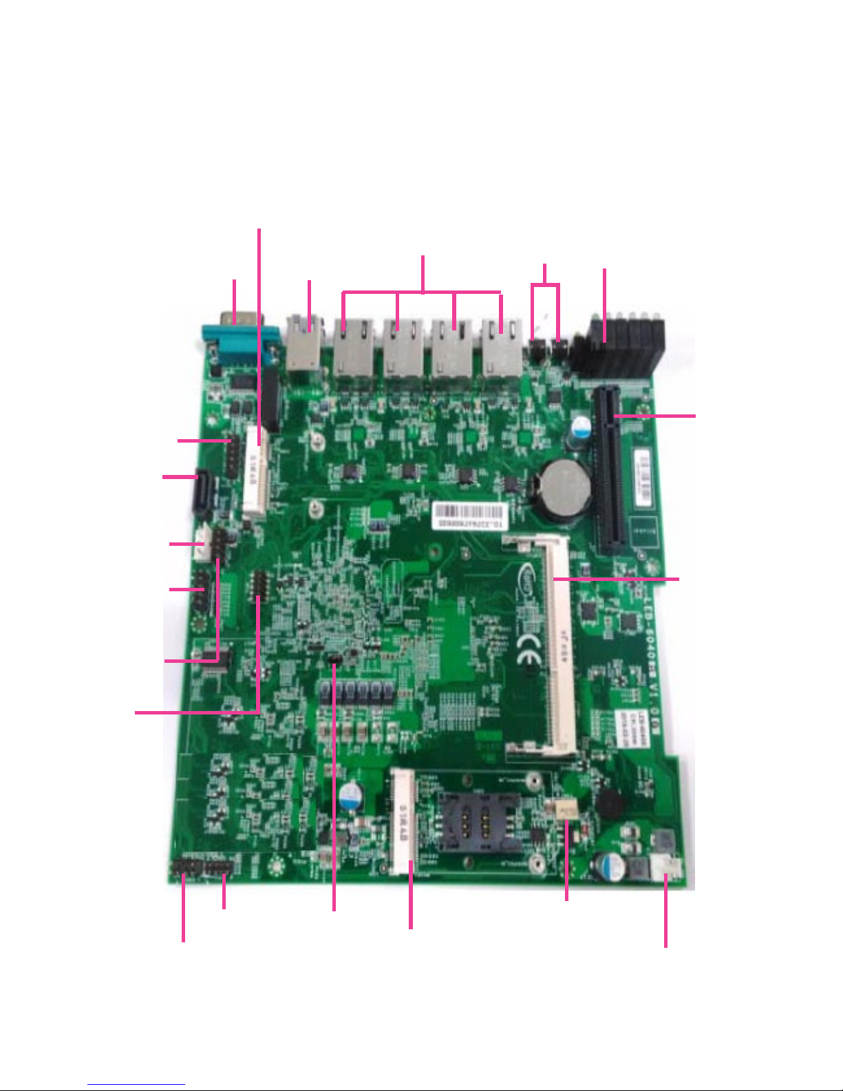
LEDs
RJ1~4 connectors
USB2
COM2
KBMS1
MPCIE1
FAN1
LPC1
DC_IN1
PCIE1
DIMM1
VGA1
COM1
USB_J1
SPI1
MPCIE2
SATA1
PWR1
Motherboard Layout
CMOS1
SW1/2
Page 13
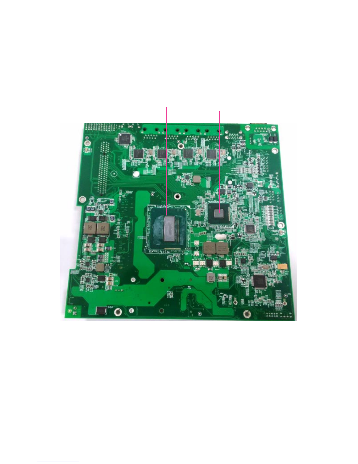
CPU
Chipset
Page 14
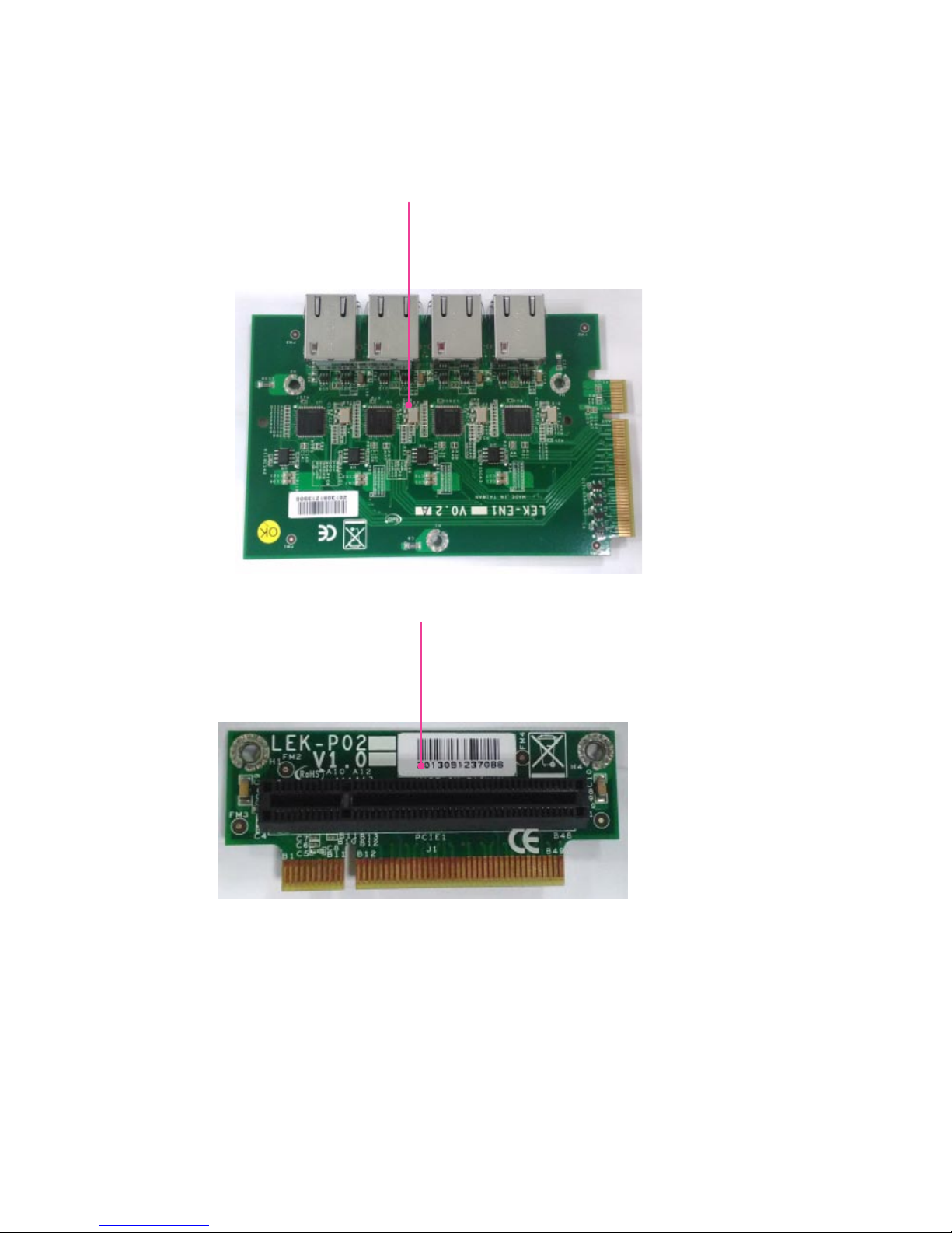
Add-on Card and Backplane
LEK-EN1: the add-on card for additional LAN ports. It comes in either 2 LAN ports or 4 LAN ports type.
The card is only available for models with 6 or 8 LAN ports. Please see Ordering Information for details.
LEK-P02 Backplane: the backplane for board-to-board connector
Add-on Card LEK-EN1
Backplane LEK-P02
Page 15

Label Descriptions
COM2 Front panel serial interface for RS-232 port
USB2 Double stacked USB port 1 and 2 on the front panel
RJ1~4
connectors
4 x RJ45 Ethernet ports on the front panel
LEDs LED signals for system activity indicators
KBMS1 Keyboard & mouse connector
LPC1 Low-pin Count: for debug use only
CF1 CompactFlash socket
DC_IN1 DC power input
MPCIE1 Full-size mini PCIe slot1: with SIM card reader
FAN1 Fan connector (unused)
USB1 Internal USB connector (unused)
MPCIE2 Half-size mini PCIe slot2 (only USB signals)
VGA1 Display purpose
SATA1&2 2 x SATA signal connectors
PWR1 4-pin SATA power connector
COM1 Internal serial connector (full RS-232 signals)
USB_J1 Internal USB pinheader
SPI1 Serial Peripheral Interface Bus: for debug use only
CMOS1 To clear CMOS
PCIE1 PCIe bus for expansion
BAT1 Lithium battery
DIMM1 DDR DIMM memory module socket
Motherboard Jumper and Connector Table
Page 16
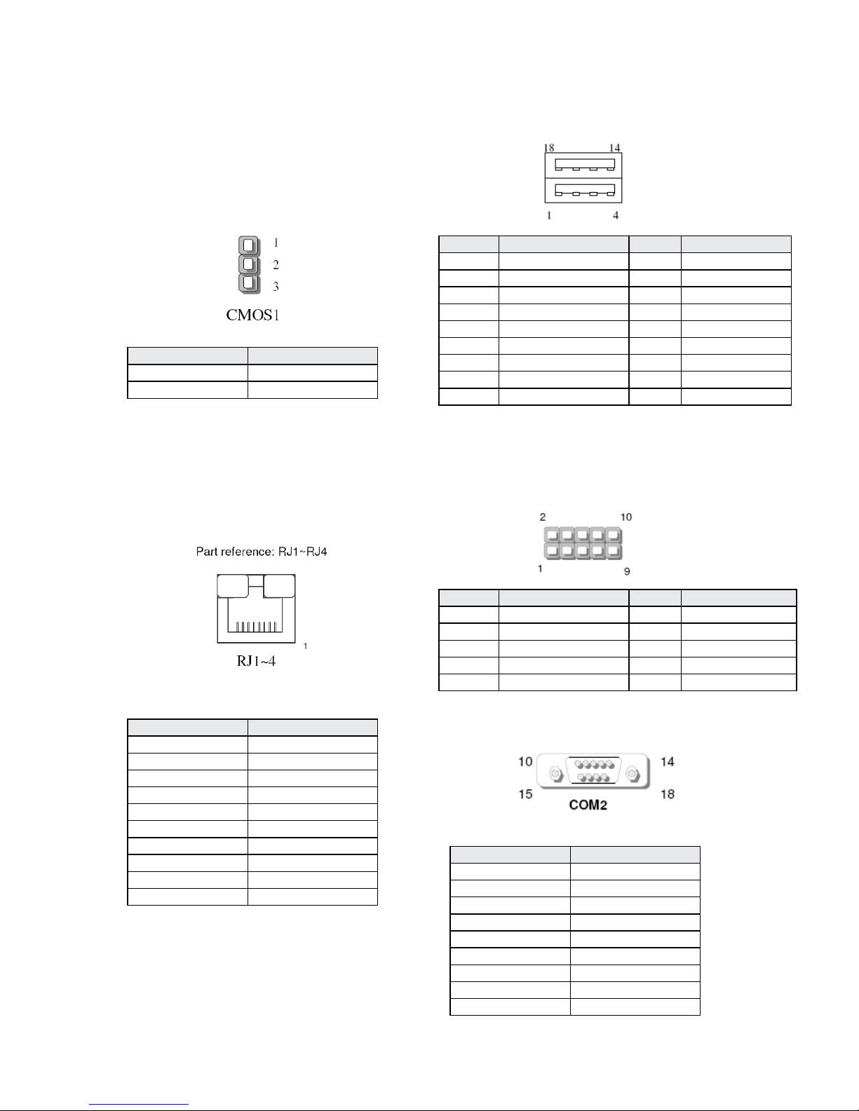
Jumper Setting & Connector Pinouts
CMOS1:
This jumper is used to erase data in CMOS. To clear CMOS, rst turn o
your system and unplug power source. Then, by placing the cap on
pin 2 and 3 (short pin 2-3), this jumper can erase the system settings
stored in CMOS memory.
Pin Short Description
Short 1-2 (Default) Normal
Short 2-3 Clear CMOS
Pin Description
1 MD0+
2 MD03 MD1+
4 MD15 CT1
6 CT2
7 MD2+
8 MD29 MD3+
10 MD3-
Ethernet Interface (RJ1~4)
4 x RJ-45 LAN ports
USB Interface (USB2)
USB 3.0 port 1 & 2 connector on the front panel
Pin Description Pin Description
1 USB power 10 USB power
2 USB2.0_DAT0- 11 USB2.0_DAT13 USB2.0_DAT0+ 12 USB2.0_DAT1+
4 Signal ground 13 Signal ground
5 USB3.0_RX0- 14 USB3.0_RX16 USB3.0_RX0+ 15 USB3.0_RX1+
7 Signal ground 16 Signal ground
8 USB3.0_TX0- 17 USB3.0_TX19 USB3.0_TX0+ 18 USB3.0_TX1+
USB Interface (USB_J1)
1 x USB 2.0 internal connector
Pin Description Pin Description
1 USB power 2 USB power
3 USB2.0_DAT2- 4 USB2.0_DAT35 USB2.0_DAT2+ 6 USB2.0_DAT3+
7 Ground 8 Ground
9 NC 10 NC
Front Panel Serial Interface with RS-232: COM2
Pin Description
1
2 Receive Data (RxD)
3 Transmit Data (TxD)
4
5 Ground
6
7
8
9
Page 17
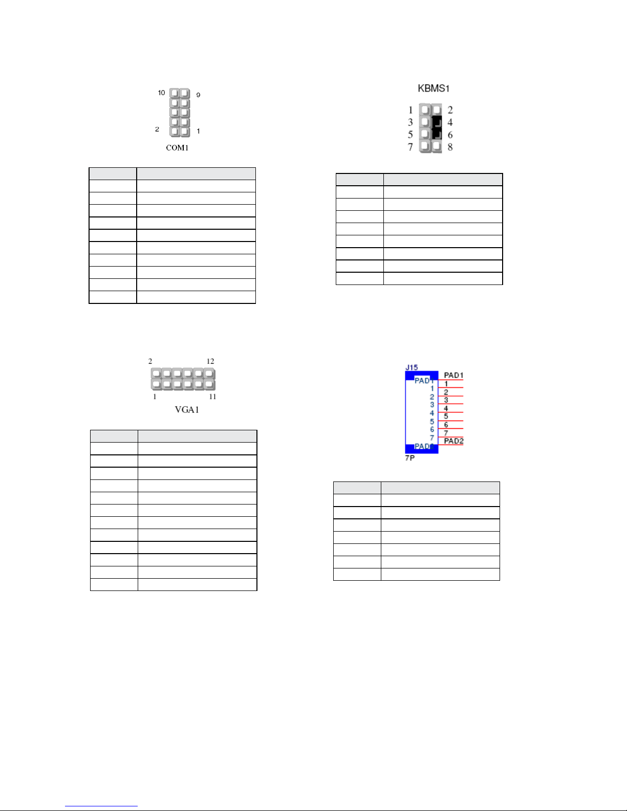
Internal Serial Interface with RS-232: COM1
Pin Description
1 Data Carrier Detect (DCD)
2 Data Set Ready (DSR)
3 Received Data (RxD)
4 Request To Send (RTS)
5 Transmit Data (TxD)
6 Clear To Send (CTS)
7 Data Terminal Ready (DTR)
8 Ring Indicator (RI)
9 Ground
10 NC
Pin Description
1 RED
2 GROUND
3 GREEN
4 GROUND
5 BLUE
6 GROUND
7 HSYNC
8 GROUND
9 VSYNC
10 GROUND
11 DDCCLK
12 DDCDATA
Pin Description
1 VCC
2 MSCLK
3 MSDAT
4 Key
5 KBDAT
6 Key
7 Ground
8 KBCLK
SATA Interface: SATA1
SATA Signal Connector
Pin Description
1 Ground
2 TX+
3 TX4 Ground
5 RX6 RX+
7 Ground
Display Interface with VGA signal: VGA1
Keyboard/Mouse Interface: KBMS1
Page 18
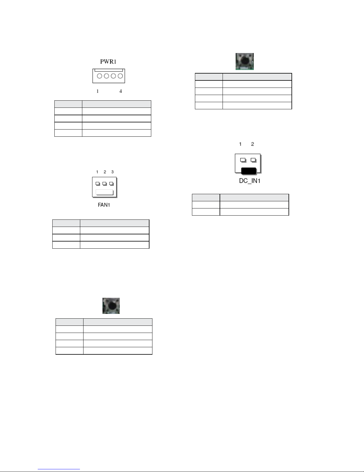
Pin Description
1 VCC12 (12V)
2 Ground
3 Ground
4 VCC (5V)
FAN connector: FAN1
Pin Description
1 Ground
2 +12V
3 FAN status
ATX Power Button:
Connector SW1
Pin Description
1 PANSW
2 GND
3 GND
4 GND
RESET Button:
Connector SW2
Pin Description
1 GND
2 SYS_RESET
3 GND
4 GND
Power Connector:
DC_IN1
Pin Description
1 VCC12 (12V)
2 Ground
SATA Interface: PWR1
SATA Power Connector
Page 19
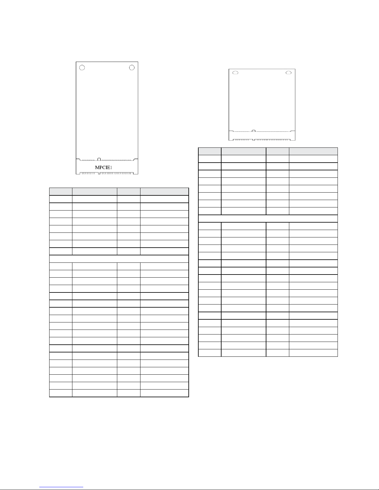
Mini PCIe Connector: MPCIE1
MPCIE1:mini PCIe Slot /w SIM (Full Size)
Pin Description Pin Description
1 WAKE# 2 +3.3V
3 RSVD 4 GND
5 RSVD 6 +1.5V
7 CLKREQ# 8 UIM_PWR
9 GND 10 UIM_DATA
11 REFCLK- 12 UIM_CLK
13 REFLCK+ 14 UIM_RESET
15 GND 16 UIM_VPP
KEY
17 RSVD 18 GND
19 RSVD 20 W_DISABLE#
21 GND 22 PERST#
23 PERn0 24 +3.3V
25 PERp0 26 GND
27 GND 28 +1.5V
29 GND 30 SMB_CLK
31 PETn0 32 SMB_DATA
33 PETp0 34 GND
35 GND 36 USB_D+
37 GND 38 USB_D39 +3.3V 40 GND
41 +3.3V 42 LED_WWAN#
43 GND 44
45 RSVD 46
47 RSVD 48 +1.5V
49 RSVD 50 GND
51 RSVD 52 +3.3V
Mini PCIe Connector: MPCIE2
MPCIE2:mini PCIe Slot (half-sized) with USB and mSATA signals
Pin Description Pin Description
1 WAKE# 2 +3.3V
3 RSVD 4 GND
5 RSVD 6 +1.5V
7 CLKREQ# 8 RSVD
9 GND 10 RSVD
11 RSVD 12 RSVD
13 RSVD 14 RSVD
15 GND 16 RSVD
KEY
17 RSVD 18 GND
19 RSVD 20 W_DISABLE#
21 GND 22 PERST#
23 SATA RX+ 24 +3.3V
25 SATA RX- 26 GND
27 GND 28 +1.5V
29 GND 30 SMB_CLK
31 SATA TX- 32 SMB_DATA
33 SATA TX+ 34 GND
35 GND 36 USB_D+
37 GND 38 USB_D39 +3.3V 40 GND
41 +3.3V 42 LED_WWAN#
43 GND 44 RSVD
45 RSVD 46 RSVD
47 RSVD 48 +1.5V
49 RSVD 50 GND
51 RSVD 52 +3.3V
Page 20
Chapter 4:
Hardware Setup
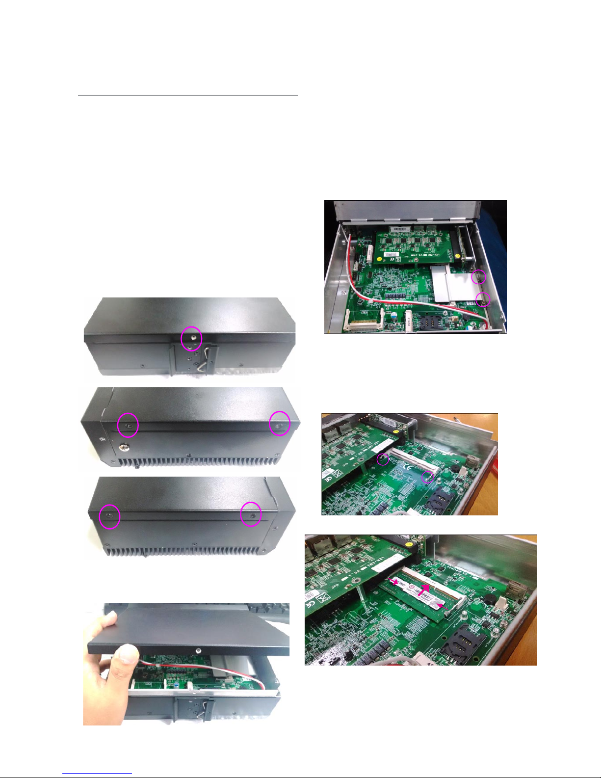
Preparing the Hardware Installation
WARNING:
To reduce the risk of personal injury, electric
shock, or damage to the equipment, please
make sure the device is totally powered off
and without any power source connected.
It is strongly recommended to wear ESD
proof gloves to conduct the following steps.
Turn the device around (facing the rear panel) and 1.
then turn it upside down.
Remove the screws circled in the image below; one at 2.
the rear and two at each side of the chassis.
3. Gently lift the compartment open.
Installing the System Memory
The motherboard supports DDR3L memory at1333/1600
MHz, up to 2GB, low-voltage, unbuffered and non-ECC.
Please make sure the DDR3L SO-DIMM module in use
meet the specifications.
Remove the SO-DIMM socket heat sink by removing 1.
the 2 screws circled in the image below.
2. Align the DIMM module to the socket, as well as the
notches, and gently pull the retention clips open, to a
slight 15 degree.
3. Once the DIMM is fully inserted, use the retention clip
to secure it.
Page 21
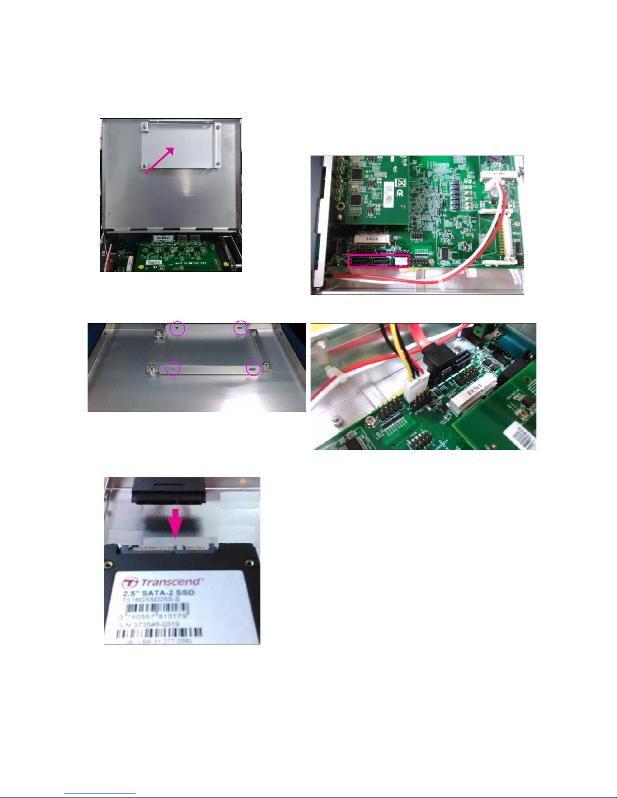
Installing a Disk Drive (HDD/SSD)
Locate the disk drive bay attached on the internal 1.
side of the top cover.
2. Place the disk drive into the bay and align the screwholes. Then, secure the disk drive with screws.
3. Connect a SATA cable to the disk drive
4. Connect the SATA cable to the SATA signal and power
connectors on the board. Remember that the board supports 4-pin SATA power connector. Please use a matching
connector.
Page 22
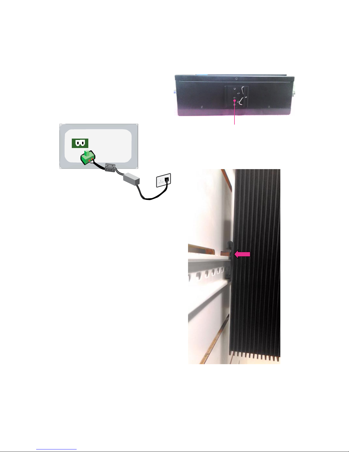
Connecting Power
Connect the LEC-6040 to a 12Vdc power source. The
power source comes from the AC/DC Adapter through a
Phoenix contact. This power socket is purposely designed to guard against fault in power contact so that
the reverse of the electrical polarity will not damage the
system.
2-pin DC_IN
-DC in +
Mounting LEC-6040M by DIN Rail
LEC-6040 is designed with a DIN Rail mounting bracket at
the rear of the product.
Hang the device onto a rail until it rmly attaches .
DIN Rail mounting use
Page 23
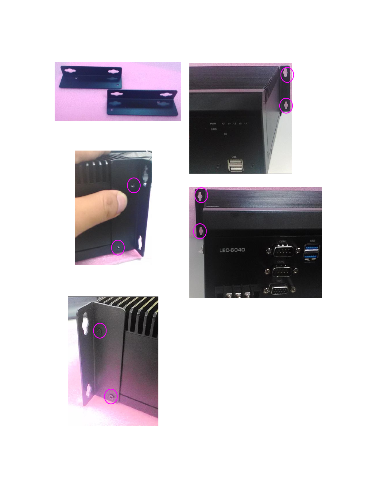
Installing the Ear Mount Brackets
1. Prepare the ear mount bracket set
2. Align the ear mount bracket to LEC-6040 and make
sure the two screw holes are aligned.
3. Apply screws to have the brackets xed. Do the same
for both sides.
4. Completed.
5. You may mount LEC-6040 on a flat surface.
Page 24
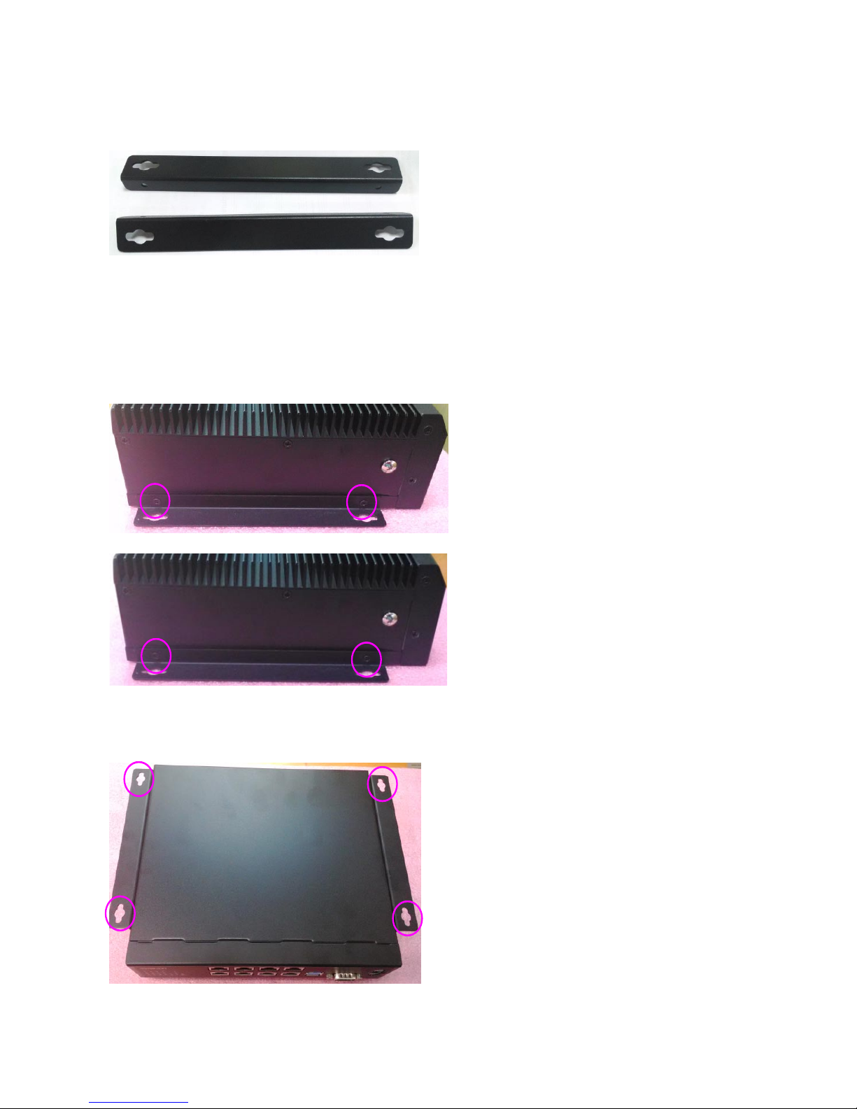
Installing the Wall Mount Brackets
1. Prepare the wall mount bracket set
2. Align the wall mount bracket to LEC-6040 and make
sure the two screw holes are aligned.
3. Apply screws to have the brackets xed. Do the same
for both sides.
4. Completed. You may mount LEC-6040 to a at surface
of a wall.
Page 25
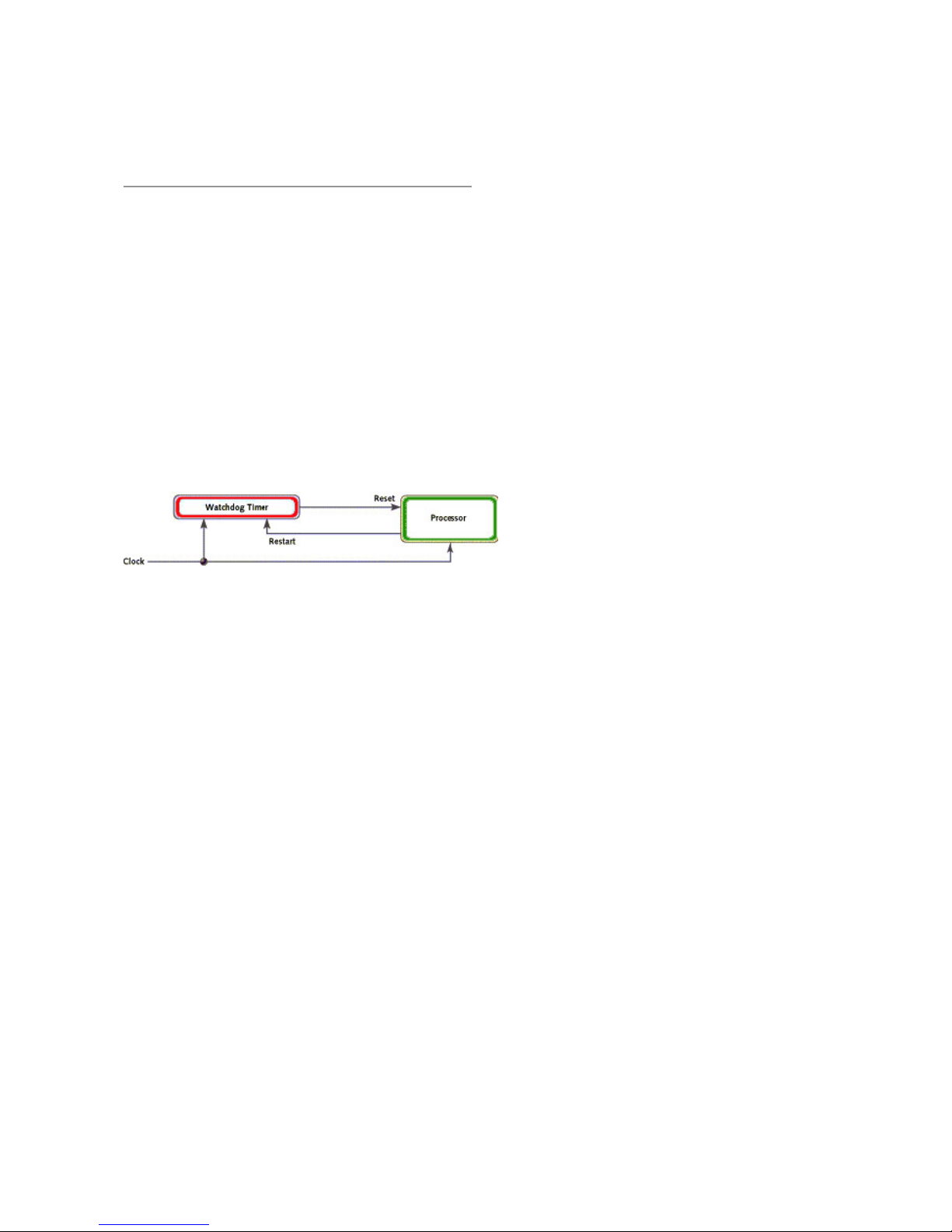
Appendix 1:
Programming Watchdog
Timer
A watchdog timer is a piece of hardware that can be
used to automatically detect system anomalies and reset
the processor in case there are any problems. Generally
speaking, a watchdog timer is based on a counter that
counts down from an initial value to zero. The software
selects the counter’s initial value and periodically restarts
it. Should the counter reach zero before the software
restarts it, the software is presumed to be malfunctioning
and the processor’s reset signal is asserted. Thus, the
processor will be restarted as if a human operator had
cycled the power.
For sample watchdog code, see WD folder under Driver
and Utility on the Driver and Manual CD
Page 26

Appendix 2:
Terms and Conditions
Warranty Policy
All products are under warranty against defects in 1.
materials and workmanship for a period of one year
from the date of purchase.
The buyer will bear the return freight charges for 2.
goods returned for repair within the warranty period;
whereas the manufacturer will bear the after service
freight charges for goods returned to the user.
The buyer will pay for repair (for replaced 3.
components plus service time) and transportation
charges (both ways) for items after the expiration of
the warranty period.
If the RMA Service Request Form does not meet the 4.
stated requirement as listed on “RMA Service,” RMA
goods will be returned at customer’s expense.
The following conditions are excluded from this 5.
warranty:
Improper or inadequate maintenance by the customer
Unauthorized modification, misuse, or reversed
engineering of the product Operation outside of the
environmental specifications for the product.
RMA Service
Requesting a RMA#
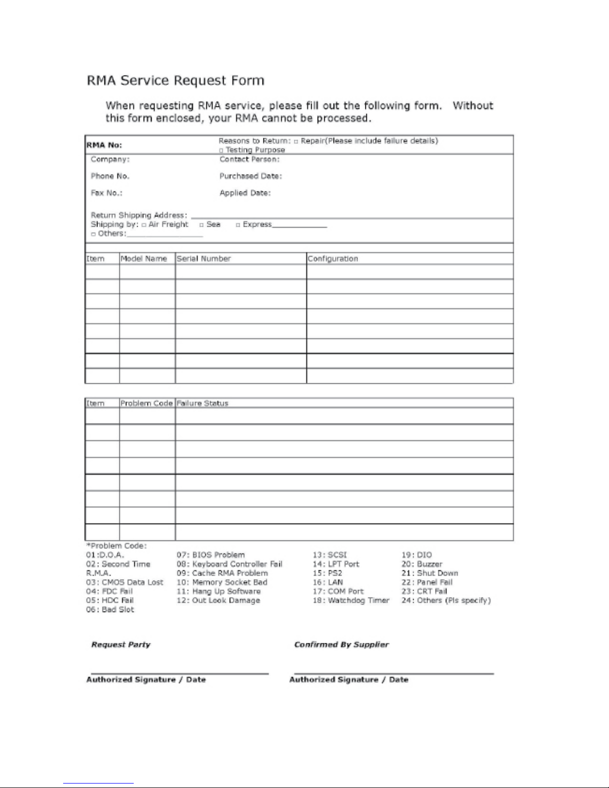
To obtain a RMA number, simply fill out and fax the 1.
“RMA Request Form” to your supplier.
The customer is required to fill out the problem code 2.
as listed. If your problem is not among the codes
listed, please write the symptom description in the
remarks box.
Ship the defective unit(s) on freight prepaid terms. 3.
Use the original packing materials when possible.
Mark the RMA# clearly on the box. 4.
Note: Customer is responsible for shipping
damage(s) resulting from inadequate/loose
packing of the defective unit(s). All RMA# are
valid for 30 days only; RMA goods received after
the effective RMA# period will be rejected.
Page 27
 Loading...