

Lanner LEC-6021A User Manual
Version: 1.3
Date of Release: 2017/06/13
LEC-6021A
User Manual
Industrial
Communications
Chapter One: Introduction
2
Icon Descriptions
The icons are used in the manual to serve as an indication of interest topics or important messages. Below is a
description of these icons:
Note: This check mark indicates that there is a note of interest and is something that you should
pay special attention to while using the product.
Warning: This exclamation point indicates that there is a caution or warning and it is something
that could damage your property or product.
Online Resources
The listed websites are links to the on-line product information and technical support.
Resources
URL
Lanner
http://www.lannerinc.com
Product Resource
http://www.lannerinc.com/download-center
RMA
http://eRMA.lannerinc.com
Copyright and Trademarks
This document is copyrighted, © 2017. All rights are reserved. The original manufacturer reserves the right to
make improvements to the products described in this manual at any time without notice.
No part of this manual may be reproduced, copied, translated or transmitted in any form or by any means
without the prior written permission of the original manufacturer. Information provided in this manual is
intended to be accurate and reliable. However, the original manufacturer assumes no responsibility for its use,
nor for any infringements upon the rights of third parties that may result from such use.
Acknowledgement
Intel, Pentium and Celeron are registered trademarks of Intel Corp.
Microsoft Windows and MS-DOS are registered trademarks of Microsoft Corp.
All other product names or trademarks are properties of their respective owners.
LEC-6021A User Manual
3
Compliances and Certification
CE Certification
This product has passed the CE test for environmental specifications. Test conditions for passing included the
equipment being operated within an industrial enclosure. In order to protect the product from being
damaged by ESD (Electrostatic Discharge) and EMI leakage, we strongly recommend the use of CE compliant
industrial enclosure products.
FCC Class A Certification
This equipment has been tested and found to comply with the limits for a Class A digital device, pursuant to
Part 15 of the FCC Rules. These limits are designed to provide reasonable protection against harmful
interference when the equipment is operated in a commercial environment. This equipment generates, uses
and can radiate radio frequency energy and, if not installed and used in accordance with the instruction
manual, may cause harmful interference to radio communications. Operation of this equipment in a
residential area is likely to cause harmful interference in which case the user will be required to correct the
interference at his own expense.
IEC-61850-3 Compliance
This product has been tested and proved to comply with IEC-61850-3 standard which defines the reliability
and endurance credentials in industrial environments. These credentials include endurable EMC design
against EMI, wide operating temperature ranging -40 ~ 70°C and shock/vibration resistance for 50G and
5~500 MHz respectively.
Safety Guidelines
Follow these guidelines to ensure general safety:
Keep the chassis area clear and dust-free during and after installation.
Do not wear loose clothing or jewelry that could get caught in the chassis. Fasten your tie or scarf and
roll up your sleeves.
Wear safety glasses if you are working under any conditions that might be hazardous to your eyes.
Do not perform any action that creates a potential hazard to people or makes the equipment unsafe.
Disconnect all power by turning off the power and unplugging the power cord before installing or
removing a chassis or working near power supplies
Do not work alone if potentially hazardous conditions exist.
Never assume that power is disconnected from a circuit; always check the circuit.

Chapter One: Introduction
4
Operating Safety
Electrical equipment generates heat. Ambient air temperature may not be adequate to cool equipment
to acceptable operating temperatures without adequate circulation. Be sure that the room in which you
choose to operate your system has adequate air circulation.
Ensure that the chassis cover is secure. The chassis design allows cooling air to circulate effectively. An
open chassis permits air leaks, which may interrupt and redirect the flow of cooling air from internal
components.
Electrostatic discharge (ESD) can damage equipment and impair electrical circuitry. ESD damage occurs
when electronic components are improperly handled and can result in complete or intermittent failures.
Be sure to follow ESD-prevention procedures when removing and replacing components to avoid these
problems.
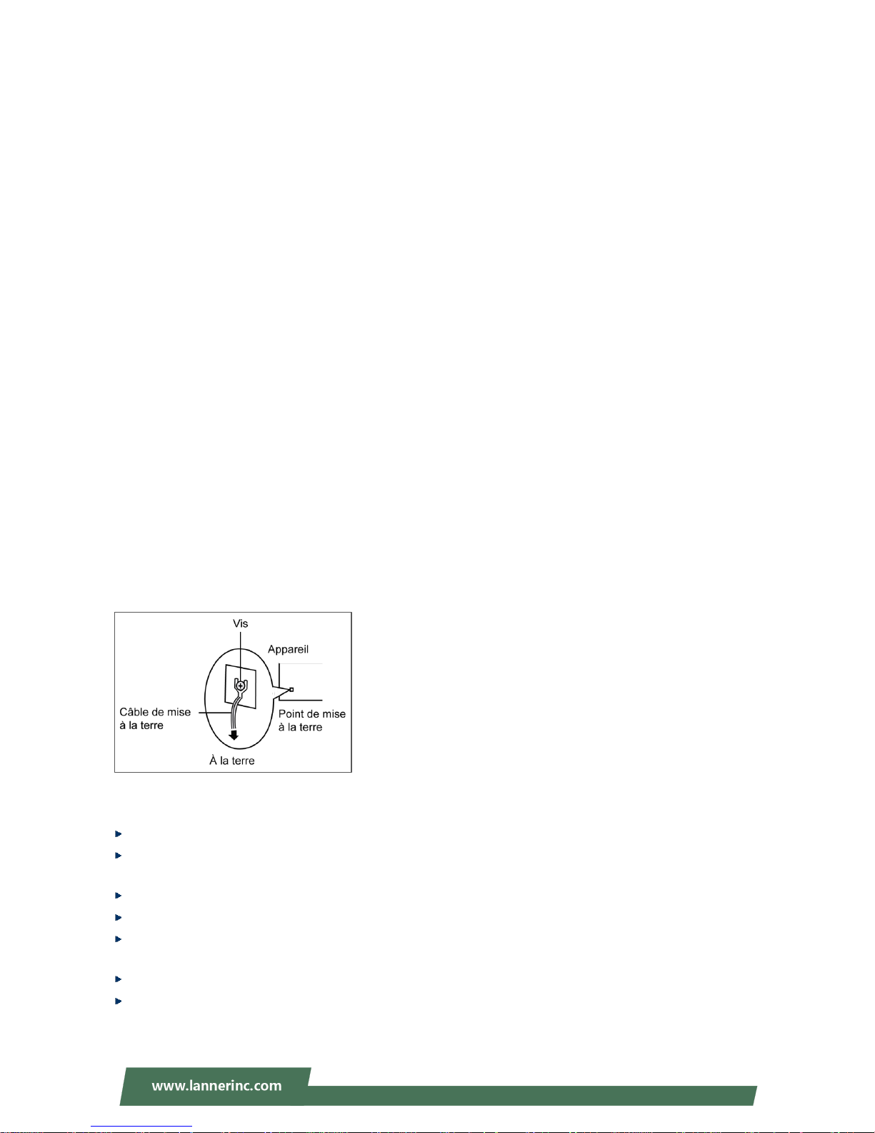
Wear an ESD-preventive wrist strap, ensuring that it makes good skin contact. If no wrist strap is available,
ground yourself by touching the metal part of the chassis.
Periodically check the resistance value of the antistatic strap, which should be between 1 and 10
megohms (Mohms).
Lithium Battery Caution
Risk of Explosion if Battery is replaced by an incorrect type.
Dispose of used batteries according to the instructions.
Installation only by a trained electrician or only by an electrically trained person who knows all English
Installation and Device Specifications which are to be applied.
Do not carry the handle of power supplies when moving to another place.
The machine can only be used in a fixed location such as labs or computer facilities.
Mounting Installation Precaution
Environment:
Do not install and/or operate this unit in any place that flammable objects are stored or used in.
Elevated Operating Ambient - If installed in a small confined space or multi-unit rack assembly, the
operating ambient temperature of the environment may be greater than room ambient. Therefore,
consideration should be given to installing the equipment in an environment compatible with the
maximum ambient temperature (Tma) specified by the manufacturer.
Reduced Air Flow - Installation of the equipment in the rack or on the wall should be such that the
amount of air flow required for safe operation of the equipment is not compromised.
Mechanical Loading - Mounting of the equipment in the rack or on the wall should be such that a
hazardous condition is not achieved due to uneven mechanical loading.
Circuit Overloading - Consideration should be given to the connection of the equipment to the supply
circuit and the effect that overloading of the circuits might have on over-current protection and supply
wiring. Appropriate consideration of equipment nameplate ratings should be used when addressing this
concern.
Reliable Earthing - Reliable earthing of the equipment should be maintained. Particular attention should
be given to supply connections other than direct connections to the branch circuit (e.g. use of power
strips).
Installation & Operation:
The installation of this product must be performed by trained specialists; otherwise, a non-specialist
might create the risk of the unit’s falling to the ground or other damages.
Lanner Electronics Inc. shall not be held liable y for any losses resulting from insufficient strength for
supporting the unit or use of inappropriate installation components.
LEC-6021A User Manual
5
Revision History
Version
Date (YYYY/MM/DD)
Description
0.1
2014/12/26
Preliminary
1.0
2015/05/26
Official release
1.1
2016/04/19
Updated motherboard
Added GND and Reset button on side panels
Modified installation images
1.2
2017/04/07
Update operating temperature
1.3
2017/06/13
Updated operating temperature spec
Updated input voltage spec
Modified rear panel image
Added wall-mounting installation narration
Updated Mounting Installation Precaution content
Added power supply information
Chapter One: Introduction
6
Table of Contents
Package Contents 7
System Specifications 8
System Drawing 9
Block Diagram 10
Front Components 11
Side Components 12
Rear Components 13
Connectors & Jumpers Locations 14
Connectors and Jumpers List 15
Jumper Settings 16
Connector Pinouts 17
Preparing the Hardware Installation 20
Installing the System Memory 21
Installing a CompactFlash Card 22
Installing Heat-sinks 23
Connecting Power 24
DIN Rail Mounting 25
Wall-Mounting 26
Warranty Policy 28
RMA Service 28

LEC-6021A User Manual
7
Thank you for choosing Lanner LEC-6021A rugged industrial system. This box PC is an industrial cyber security
appliance featuring ESD-protected serial communication and LAN ports. LEC-6012A is compliant with IEC
61850-3 for power substation automation and suitable for harsh environment. Other useful features of
LEC-6021A include the following:
Onboard Intel Atom N2600 with Intel NM10 chipset
Five gigabit Ethernet RJ-45 and two SFP ports
Two USB type A ports
One serial communication port with RS-232 signals
IEC 61850-3 compliance
LED indicators of power/HDD/status, COM activity, and LAN traffic on the front panel to indicate the
system running status
Wide operating temperature: -40°C to +70°C
Please refer to System Specifications for a detailed description of the system's specifications.
Package Contents
Your package shall contain the following items:
LEC-6012A Fanless Embedded System
Drivers and User’s Manual CD
Wall-mounting Accessories
Chapter One: Introduction
8
System Specifications
Processor Options
Intel® Atom™ N2600 1.6 GHz
Chipset
Intel NM10
BIOS
AMI SPI Flash ROM
System Memory
Sockets
1 x 204-pin DDR3 SODIMM socket
Max. Capacity
2 GB
USB
USB 2.0 compliant hosts x 2, Type A
connector
Operating System Support
Linux 2.6, Windows 7 & Embedded
Storage
1x SATA connector for SSD/HDD (optional)
CompactFlash socket
Networking
LAN
5x Ethernet LAN ports with one pair of
bypass
Controller
Intel 5x I210IT x PCI-express GbE controllers
2x I210IS x PCI-express Gigabit SFP
controller
Magnetic Isolation Protection
1.5 KV built-in
Serial Interface
Serial Standard
1 x DB9 supports RS-232 with optical
isolation
ESD Protection
Digital isolation protection with 15KV ESD
protection
Display
Graphics Controller
Intel integrated Intel HD 4600, VGA port: up
to 1920x1200(Pin Header)
Display Interface
1 x VGA by internal pin header
LEDs
Power, HDD, Status, Rx & Tx for COM,
Link/Act & Speed LED for LAN1~5,
Link/ACT/LED for LAN6 & 7
Physical
Characteristics
Housing
Steel Aluminum
Weight
2 kg
Dimensions(HxWxD)
186 x 53.5 x 160 mm
Mounting Options
DIN rail and wall mount
Environment
Operating Temperature
-40~70°C
Storage Temperature
-40~85°C
Ambient Relative Humidity
5 to 95% (non-condensing)
Shock
50G
Vibration
5~500 Mhz
Power
Input Voltage
+18~48 V DC
Power Consumption
TBD
Connector
6-pin terminal block
Standard and Regulation
EMC
CE, FCC
Green product
RoHS
Others
IEC 61850-3 Compliance
Reliability
Alter tool
Built-in buzzer and RTC (real-time clock) with
lithium battery backup
Automatic Reboot Trigger
Watchdog Timer 1~255 level time
interval system reset, software
programmable
LEC-6021A User Manual
9
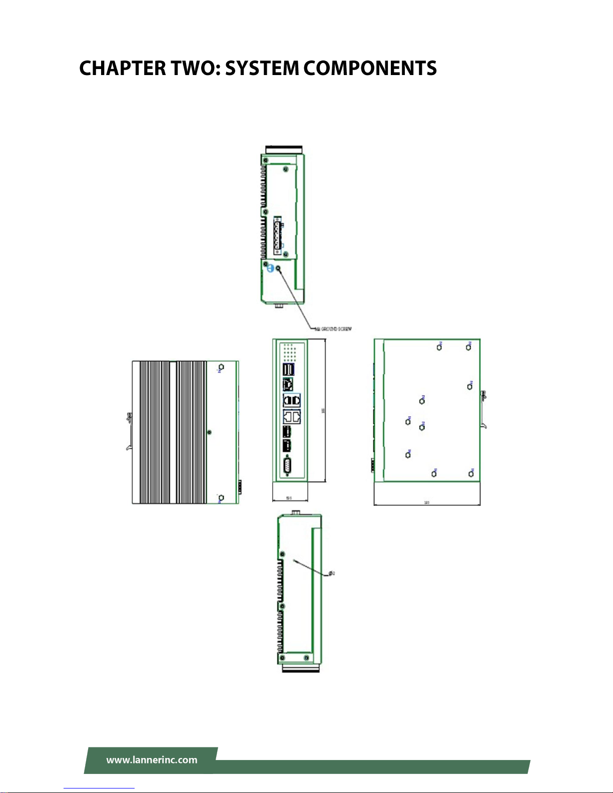
System Drawing
Mechanical dimensions of LEC-6021A
Unit: mm
 Loading...