

Page 1

Embedded &
Industrial Computing
Hardware Platforms for Embedded and Industrial Computing
LEC-3110
Version 1.0
User's Manual
Publication date:2012-01-06
>>
Page 2

TTaTTable of Contentsbeable of Contents
Chapter 1: Introduction 1
System Specication . . . . . . . . . . . . . . . . . . . . . . . . . . . . . . . . . . . . . . . . . . . 1
Package Contents . . . . . . . . . . . . . . . . . . . . . . . . . . . . . . . . . . . . . . . . . . . . . 2
Front Panel Features. . . . . . . . . . . . . . . . . . . . . . . . . . . . . . . . . . . . . . . . . . . . 3
Rear Panel Features . . . . . . . . . . . . . . . . . . . . . . . . . . . . . . . . . . . . . . . . . . . . 4
Chapter 2: Hardware Setup 6
Preparing the Hardware Installation. . . . . . . . . . . . . . . . . . . . . . . . . . . . . . . . . . 6
Installing the System Memory . . . . . . . . . . . . . . . . . . . . . . . . . . . . . . . . . . . . . 6
Installing the Hard Disk . . . . . . . . . . . . . . . . . . . . . . . . . . . . . . . . . . . . . . . . . 6
Installing a CompactFlash Card. . . . . . . . . . . . . . . . . . . . . . . . . . . . . . . . . . . . . 7
Chapter 3: Motherboard Information 8
Block Diagram . . . . . . . . . . . . . . . . . . . . . . . . . . . . . . . . . . . . . . . . . . . . . . . 8
Motherboard Layout . . . . . . . . . . . . . . . . . . . . . . . . . . . . . . . . . . . . . . . . . . . 9
Jumper Settings . . . . . . . . . . . . . . . . . . . . . . . . . . . . . . . . . . . . . . . . . . . . . .10
Appendix A: Programming Watchdog Timer 14
Appendix B: Driver Installation 19
Chipset Driver Installation . . . . . . . . . . . . . . . . . . . . . . . . . . . . . . . . . . . . . . . .19
LAN Adapters Driver Installation. . . . . . . . . . . . . . . . . . . . . . . . . . . . . . . . . . . .20
On the Windows OS . . . . . . . . . . . . . . . . . . . . . . . . . . . . . . . . . . . . . . . . .20
On Linux . . . . . . . . . . . . . . . . . . . . . . . . . . . . . . . . . . . . . . . . . . . . . . . .21
VGA Driver Installation . . . . . . . . . . . . . . . . . . . . . . . . . . . . . . . . . . . . . . . . . .22
On the Windows OS . . . . . . . . . . . . . . . . . . . . . . . . . . . . . . . . . . . . . . . . .22
On Linux . . . . . . . . . . . . . . . . . . . . . . . . . . . . . . . . . . . . . . . . . . . . . . . .22
Appendix C: Terms and Conditions 23
Warranty Policy . . . . . . . . . . . . . . . . . . . . . . . . . . . . . . . . . . . . . . . . . . . .23
RMA Service . . . . . . . . . . . . . . . . . . . . . . . . . . . . . . . . . . . . . . . . . . . . . .23
i
Page 3

Chapter 1
Chapter 1: Introduction
Introduction
The LEC-3110 embedded platform was built on the Intel
D525 processor and ICH8M Chipset. With the built-in 10
RS232/422/485 serial ports and PCI-104 connector, the
system aims to meet your needs of rich I/O connectivity
and high availability in a industrial-standard housing
(heavy steel). Furthermore, for extra protection for
the system, the LEC-3110 employs ESD (ElectroStatic
Discharge) Protection of 15KV and Surge Digital Isolation
of 2KV on all its external ports (USB, VGA, COM ports) as
well as the DC power socket which is especially designed
to serve as a redundant power supply method.
The LEC-3110 system also features a modulized concept
of board design. It allows a quick replacement or removal
of the expanded ports.
Some characteristics about the connectors are as the
following:
Ethernet - 6 Ethernet controllers •
supporting10/100/1000 connection speed with Intel
82574 L controllers (all with magnetic isolation of
2KV) and LAN1 and LAN2 support WOL/PXE
VGA with Intel Pineview D integrated graphics •
controller
Support VGA output ( Maximum resolution 1280 x •
1024)
Storage - One CF socket and 2 SATA ports (ports come with
+5v DC output in the 7th pin, auto-detecting to support
SATA-DOM)
10 COM ports- 2 in the DB9 form factor, the remaining 8 in
a terminal block form factor. All serial ports are capable of
handling RS-232/422/485 signals via a DIP-switch setting.
Other features include auto-flow control, up to 15KV in
electrostatic discharge protection and 2KV of surge digital
isolation protection.
3 USB Ports - 2 on the front panel and one on the board as
an internal USB type A connector (all with ESD Protection
15KV)
Please refer to the chart below for a detailed description
of the system’s specifications.
System Specification
FEATURE
Platform
Memory
Storage
Networking
Video
Audio
I/O
Hardware
Monitor
OS Supported
DESCRIPTION LEC-3110
Form Factor 1U Rackmount
Processor
Chipset Intel ICH8M
BIOS AMIBIOS with 8Mbit FWH
Max. FSB 1333 MHz
Memory IC On Board On Board 1G DDR3
Memory Socket
Max Memory 4GB
Compact Flash 1 x CF Socket Type I/II
SATA 1 x 2.5” SATA HDD/DOM
IDE 1 x 44-pin IDE header
Controller (Interface) Intel 82574L x 6
Controller Intel GMA3150
Codec ALC888 HD Codec
COM Ports
USB 2.0 3 (2 x External, 1 x Internal)
LAN
Expansion PCI-104
Controller Fitek 81865F hardware monitor
Watchdog timer Yes (1~255 level)
Intel Atom D525
1.8 GHZ
1 x SODIMM (DDR3 up to 4GB
per slot)
2 x DB9 (ESD protection of
15KV and Surge Digital Isolation
of 2KV)
2 x 10 pin Terminal Block x 2
All ports are isolated and can
use RS-232/422/485 control
signals (ESD protection of 15KV
and Surge Digital Isolation of
2KV)
Corresponding LEDs on front
panel
6 x RJ45 GbE, LEDs on front
panel
Embedded Windows XP/Linux
kernel 2.4.16 or above/WindowsXP 32 bit
Embedded and Industrial Computing
1
Page 4

Chapter 1
Introduction
Environmental Parameters
Dimensions
Power
Compliance
Operating Temperature
(With Industrial Components:
CF, Memory, SSD,
HDD)
Operating Temperature
(With Commercial
Components)
Extended Operating
Temperature Tested
W x H x D 301 x 38.3 x 440 mm
Weight 3 Kg/6.6 lbs
DC Power Input 12V ~ 36V DC in
AC Power Input
-10°~55°C / 14°~131°F
-5°C~45°C / 23°~113°F
Extending operating range up
to +70 °C (72-hr full loading
operation tested) and down
to -40 °C (system successfully
boot after 24-hr test)
110/240V AC in,
10% Tolerence
CE, FCC, RoHS
Package Contents
Your package contains the following items:
LEC-3110 Embedded System •
Rack Mounting Kit •
Drivers and User’s Manual CD •
Embedded and Industrial Computing
2
Page 5
Chapter 1
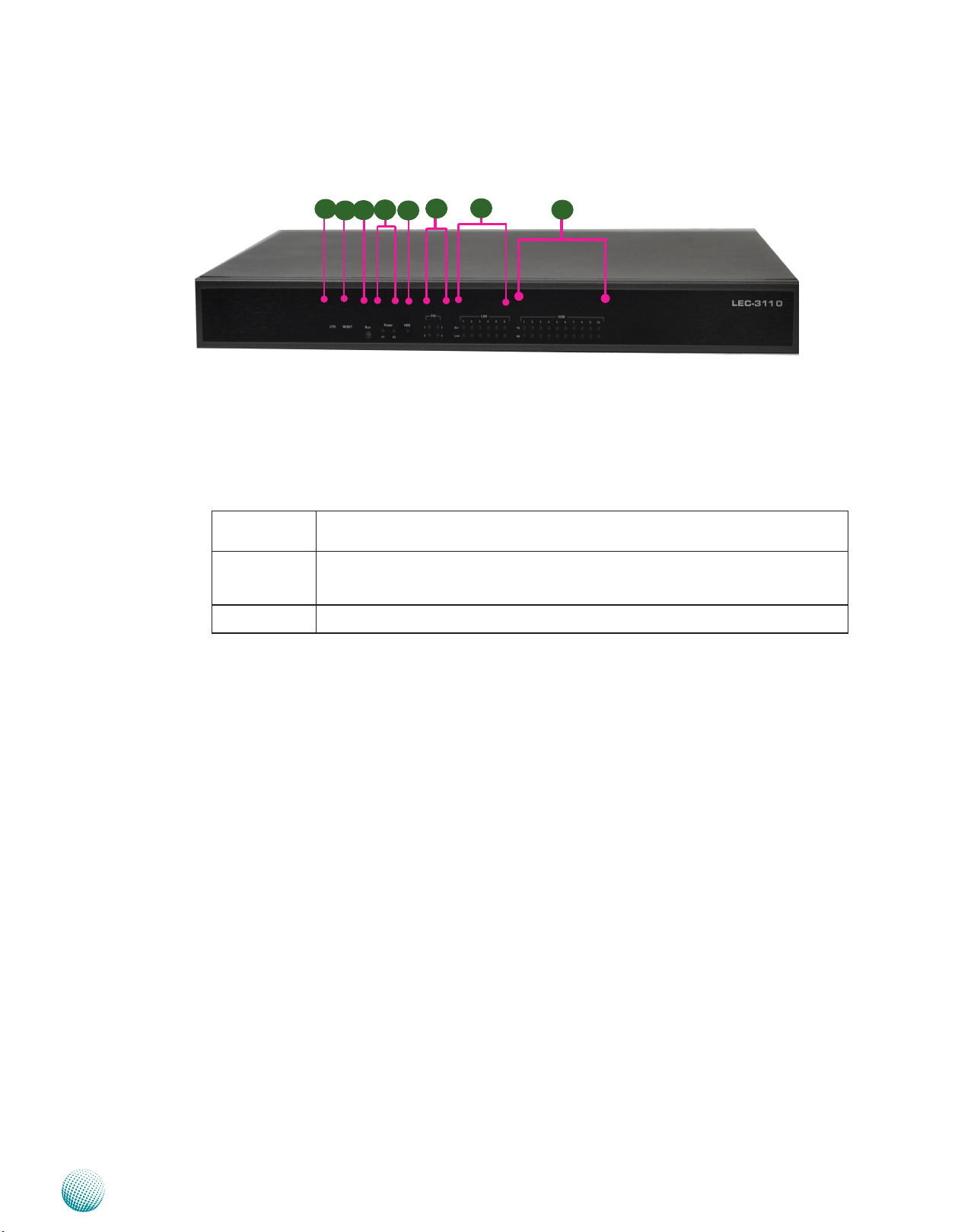
Front Panel Features
F1 CTR
This is a software reset switch which could be programmed to reset your application to its default settings.
F2 Reset Switch
It is a hardware reset switch. Use a pointed object to press it 5 seconds then release it to reset the system without
turning off the power.
F3 F4 F5 Run/Power/HDD LED
Introduction
F7
F1
F4
F3
F2
F6
F5
F8
Run A programmable dual green/amber LED which can be used for indicating system
status.
Power Green indicates Power-on, where as Off indicates Power-off status.
P1: Status for the built-in power supply unit.
P2: Status for the redundant 1x2-pin Phoenix Contact
Hard Disk Yellow indicates that HDD is present, whereas Off indicates HDD is not present.
F6 PIO Status LED
The set of 4 LEDs can be programmed to display the status of any hardware components or system operating
status. Refer to the Driver and Manual CD for a sample code to implement this feature.
F7 LAN Status LED
ACT LED: If the LED is on, it indicates that the port is linked.
Link LED: If it blinks, it indicates there is traffic.
F8 Serial Port Status LED for COM1 through COM10
The LEDs on the upper row show the status of transmission activities, whereas those on the bottom row show
the status of receiving activities.
Embedded and Industrial Computing
3
Page 6
Chapter 1
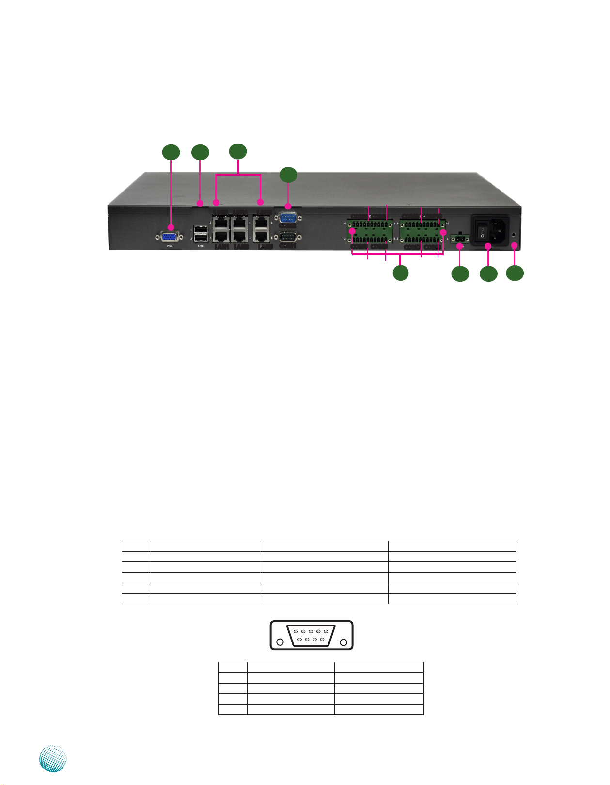
Rear Panel Features
Introduction
R1
R1 VGA Connector
R2
R3
LAN2 LAN4 LAN6
LAN1 LAN3 LAN5
R4
COM2
COM1
Pin 1
Pin 1
COM4 COM6
COM3 COM5
Pin 1
Pin 1
Pin 1
COM8 COM10
COM7 COM9
Pin 1
R5
Pin 1
Pin 1
R6
R7
R8
The VGA is provided by the integrated GPU which implements Intel® Graphics Media Accelerator 3150.
R2 Two USB 2.0 type A ports
It connects to any USB devices, for example, a flash drive. There is another external port on the front panel
and one internal USB dip connector on the mainboard. They all have ESD Protection of 15KV.
R3 6 Gigabit Ethernet LAN ports
LAN 1-6 are provided by Intel 82574L Ethernet controller which supports10/100/1000Mbps connection
speeds. In addition, LAN1 and LAN2 Support Wake-on-LAN (WOL) and Preboot eXecution Environment
(PXE).
Using suitable RJ-45 cable, you can connect LEC-3110 System to a computer, or to any other piece of
equipment that has an Ethernet connection such as a hub or a switch.
R4 Two RS-232 Serial Port (Bottom: COM1, Upper: COM2, fully compliant to RS-232 standard)
These two serial ports have default operation mode of RS-232 communication channel, but can be configured
as either RS-422 or RS-485 serial communication channel through dip switch selection. Refer to Chapter 3
Motherboard Information for dip switch information. They are capable of 15KV ESD (ElectroStatic Discharge)
Protection and 2KV Surge Digital Isolation.
Pin No. Pin name for RS-232 Pin name for RS-485/RS-422 Pin name for RS-485(2 wires)
1 Data Carrier Detect (DCD) TXD- DATA2 Received Data (RXD) TXD+ DATA+
3 Transmitted Data (TXD) RXD+
4 Data Terminal Ready (DTR) RXD5 Signal Ground (GND) Ground (GND)
1 2 3 4 5
6 7 8 9
Pin No. Pin name for RS-232 Pin name for RS-485
6 Data Set Ready (DSR)
7 Request to Send (RTS)
8 Clear to Send (CTS)
9 Ring Indicator (RI)
R5 20-pin Phoenix Contact Terminal Block
Embedded and Industrial Computing
4
Page 7

Chapter 1
This terminal block can be connected as 8 Com ports with serial port type of RS-232, RS-422 or RS-485; it
supports dip switch selection among RS-232, RS-422 and 485. The following table lists the pin assignments.
Refer to Chapter 3 Motherboard Information for dip switch adjustment information. Note that Pin 1 starts from
right. They are capable of 15KV ESD (ElectroStatic Discharge) Protection and 2KV Surge Digital Isolation.
Introduction
Pin NO.
Port Type
RS-232 TXD RTS RXD CTS Ground
RS-422 TX+ TX- RX- RX+ Ground
RS-485 TX+ TX- RX- RX+ Ground
RS-485 (2 wires) DATA+ DATA- Ground
R6 Redundant Power Supply Socket
A redundant power supply through 1x2-pin Phoenix Contact with 12~36V is provided on the system. It has
ESD Protection for15KV and surge Digital isolation for 2KV. The socket also features reverse polarity protection.
Hence, it will not cause any damage to the system by reversed wiring of ground line and power line.
12
R7 Power Switch
The power switch comes with the switch which can be used to turn on/off the power from the power supply.
R8 Power Socket
The AC inlet comes from the unit’s built-in 150W open frame power.
Pin 1 Pin 2 Pin 3 Pin 4 Pin 5
(GND)
(GND)
(GND)
Pin No. 1 2
Function DC + / - DC - / +
Embedded and Industrial Computing
5
Page 8

Chapter 2
Introduction
Chapter 2: Hardware Setup
Preparing the Hardware Installation
To access some components and perform certain service
procedures, you must perform the following procedures
first.
WARNING: To reduce the risk of personal injury,
electric shock, or damage to the equipment,
remove the power cord to remove power from the
server. The front panel Power On/Standby button
does not completely shut off system power.
Portions of the power supply and some internal
circuitry remain active until AC power is removed.
Unscrew the 6 threaded screws from the top cover of 1.
the LEC-3110 System.
Slide the cover backwards and open the cover 2.
upwards.
1
Installing the Hard Disk
The system can accommodate one Serial-ATA disks. Follow
these steps to install a hard disk into the LEC-3110:
Unscrew the 4 screws on the hard disk tray to take out 1.
the hard disk tray from the system.
Place hard disk on the hard disk tray and align the holes 2.
of the hard disk with the mounting holes of the tray.
Secure the hard disk with 4 mounting screws on the 3.
hard disk tray.
Connect the Serial-ATA power and drive cables to the 4.
hard disk’s power and data connectors respectively.
Plug the Serial-ATA data cable to the Serial-ATA 5.
Connector on the main board.
Plug the Serial-ATA power cable to the Serial-ATA 6.
Power Connector on the main board.
Put the hard disk tray with the installed hard disk back 7.
and fasten it to the system with the mounting screws.
Installing the System Memory
The motherboard supports DDR2 memory It comes with
one Double Data Rate(DDR2) Small Outline Dual Inline
Memory Modules (SO-DIMM) socket.
Align the cutout of the SO-DIMM with the notch of the 1.
memory slot.
Install the SO-DIMM.2.
Notch
Cutout
Note:
The system already has 1GB onboard memory 1.
and can support additional memory with the
DDR3 SO-DIMM socket up to 4 GB in maximum.
Embedded and Industrial Computing
6
Page 9

Chapter 2
Installing a CompactFlash Card
LEC-3110 provides one CompactFlash slot. Follow the
procedures bellow for installing a CompactFlash card.
Align CompactFlash card and the card slot with the 1.
arrow pointing toward the connector.
Push the card to insert into the connector.2.
Introduction
1
2
Embedded and Industrial Computing
7
Page 10

Chapter 3
Intel Atom Process
D525
Micro-FCBGA8
Intel
ICH8-M
mBGA
31mm x 31mm
LPC
DDR3 1333 MHz
4xDMI
Compact Flash
1x USB
Internal DIP PCB
Connector
2x USB
connectors
USB 2.0
SATAII
2 x SATAII Port
Up to 4GB Maximum
Fintek
81865F
4 x COM ports
Flash
BIOS
IDE
Integrated
graphic engine
VGA connector
LEB-3110
Hardware Monitor
6x GbE RJ-45
Connectors w/ LED
6x PCI-E
SPI
Intel 82574L
GbE
Intel 82574L
GbE
Intel 82574L
GbE
Intel 82574L
GbE
Intel 82574L
GbE
Intel 82574L
GbE
GPIO
PCI
6 x COM ports
PCI-104
PCI Connector
HD
Audio
ALC 888
Audio Codec
MIC IN
LINE IN
LINE OUT
(Reserved)
2 x Pin Headers
IDE Pin Header
(reserved)
Onboard 1G
Chapter 3: Motherboard Information
Block Diagram
The block diagram depicts the relationships among the
interfaces or modules on the motherboard. Please refer
to the following figure for your motherboard’s layout
design.
Motherboard Information
Embedded and Industrial Computing
8
Page 11

Chapter 3
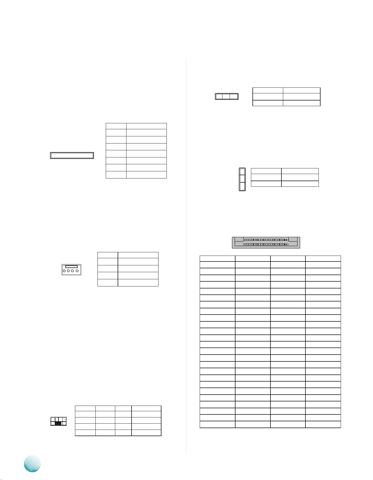
Motherboard Layout
The motherboard layout shows the connectors and
jumpers on the board. Refer to the following picture
as a reference of the pin assignments and the internal
connectors.
Motherboard Information
LEB-3110
System Board
SW1 SW2 SW3 SW4
LEK-COM08
COM Daughter Board
LEK-AD01
DC/DC
Converter
Embedded and Industrial Computing
9
Page 12
Chapter 3
25 1
50 26
Motherboard Information
Jumper Settings
SATA Connector (J10, J11): The system supports one
SATA drive with a transfer rate of 3.0 Gb/s. This port
support both SATA and SATA DOM and detects between
them automatically.
Pin No. Function
1 GND
2 TX+
3 TX-
7 6 5 4 3 2 1
SATA Power Connector (J3): Connect the 4-pin SATA
power connector to this port.
4 GND
5 RX6 RX+
7 5V
Clear CMOS jumper (JP2): It is for clearing the CMOS
memory and system setup parameters by erasing the data
stored in the CMOS RAM such as the system passwords.
Pin No. Function
1-2 Normal (Default)
3 2 1
2-3 Clear CMOS
CompactFlash Primary/Slave Selection Jumper (JP1):
The system’s CompactFlash connects to LEC-3110’s
Primary IDE port in parallel with a reserved IDE connector.
This jumper configures the CF socket to be the Master
(default) or Slave IDE device.
1
2
3
Pin No. Function
1-2 Master (Default)
2-3 Slave
CompactFlash Connector (CN2): It is for connecting a
Compact Flash card to be served as your system’s storage.
The connector is a CF Type II slot which could fit both CF
Type I or CF Type II cards.
1 2 3 4
Pin No. Function
1 VCV12 (12V)
2 GND
3 GND
4 VCC (5V)
Pin No. Function Pin No. Function
1 GND 26 CF_CD1#
2 CF_DD3 27 CF_DD11
3 CF_DD4 28 CF_DD12
4 CF_DD5 29 CF_DD13
5 CF_DD6 30 CF_DD14
6 CF_DD7 31 CF_DD15
7 CF_DCS0# 32 CF_DCS1#
8 A10(GND) 33 VS1#
9 OE#(GND) 34 CF_DIOR#
10 A9(GND) 35 CF_DIOW#
11 A8(GND) 36 WE#(VCC3)
12 A7(GND) 37 CF_IRQ#
13 VCC 38 VCC
14 A6(GND) 39 CSEL#(GND)
15 A5(GND) 40 VS2#
Keyboard and mouse interface Connectors(J7): It is
for connecting the PS/2 keyboard and mouse interface
cable.
16 A4(GND) 41 CF_RESET#
17 A3(GND) 42 CF_IORDY
18 CF_A2 43 CF_DMARQ
19 CF_A1 44 CF_DDACK#
20 CF_A0 45 CF_ACT#
21 CF_DD0 46 CF_DIAG
2 4 6 8
1 3 5 7
Pin No. Function Pin No. Function
1 VCC 2 MSCLK
3 MSDAT 6 KEY
5 KBDAT 6 KEY
7 GND 8 KBCLK
22 CF_DD1 47 CF_DD8
23 CF_DD2 48 CF_DD9
24 WP(NC) 49 CF_DD10
25 CF_CD2# 50 GND
.
Embedded and Industrial Computing
10
Page 13
Chapter 3
Motherboard Information
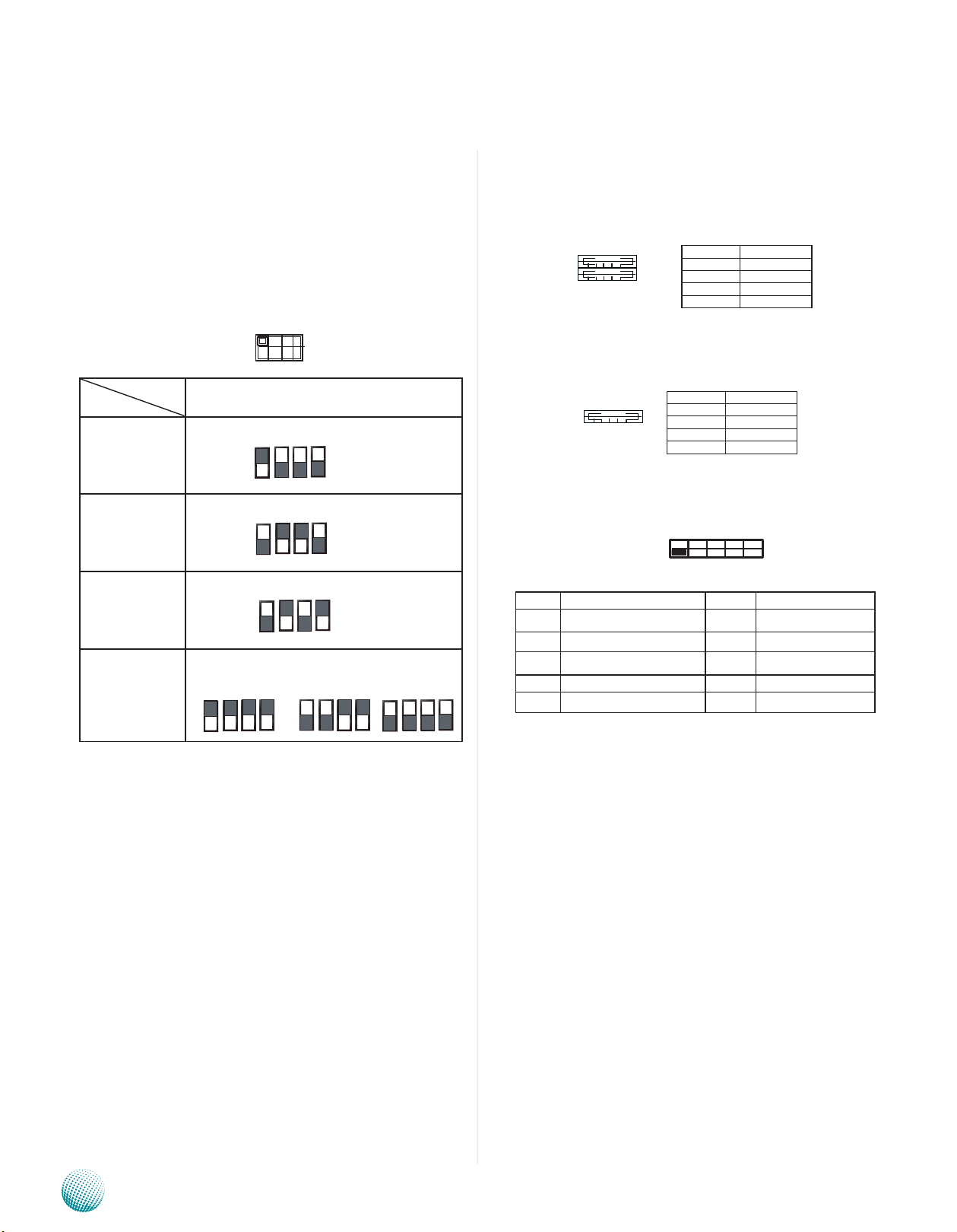
SW1/SW3 (on LEB-3110) and SW1/SW2/SW3/SW4/SW9/
SW10/SW11/SW112 (on LEK-COM08): These switches —
SW1, SW3 (on LEB-3110) and SW1, SW2, SW3, SW4, SW9,
SW10, SW11, SW12 (on LEK-COM08) — are used to adjust
the serial port type for COM1, COM2, COM3, COM4, COM5,
COM6, COM7, COM8, COM9, and COM10 respectively. Use
the table below for the dip switch adjustment information
for COM1 through COM10.
12 3 4
ON
OFF
COM Port No.
Port Type
RS-232 The respective switch for each COM Port:
RS-422 The respective switch for each COM Port:
RS-485 The respective switch for each COM Port:
Termination
(Enable for TX, RX/
Enable for RX only/
disable)
Enable: TX, RX ON Enable: RX ON Disable: OFF
COM 1 through COM10
1 ON
2 OFF
3 OFF
4 OFF
1 OFF
2 ON
3 ON
4 OFF
1 OFF
2 ON
3 OFF
4 ON
The respective switch for each COM Port:
USB Port 1-2 Connector (USB1): These external USB type
A connectors comply with USB2.0 and support up to 480
Mbps connection speed.
Pin No. Function
1 USB power
2 USB_DAT-
1 2 3 4
3 USB_DAT+
4 GND
USB DIP PCB Connector (J9): An optional internal USB
2.0 type A connector.
Pin No. Function
1 USB power
4 3 2 1
2 USB_DAT3 USB_DAT+
4 GND
Serial Interface Connectors for COM11 and COM 12
(J4, J5): It is for connecting the RS-232 serial port module
cable.
9 7 5 3 1
10 8 6 4 2
PIN No. Function PIN No. Function
1 Data Carrier Detect (DCD) 2 Data Set Ready (DSR)
3 Received Data (RxD) 4 Request To Send (RTS)
5 Transmitted Data (TxD) 6 Clear To Send (CTS)
7 Data Terminal Ready (DTR) 8 Ring Indicator (RI)
9 Signal Ground 10
SW2/SW4 (on LEB-3110) and SW5/SW6/SW7/SW8/
SW13/SW14/SW15/SW16(on LEK-COM08)
These switches — SW2, SW4 (on LEB-3110) and SW5,
SW6, SW7, SW8, SW13, SW14, SW15, and SW16 (on
LEK-COM08)— are used to enable or disable the signal
termination for COM1, COM2, COM3, COM4, COM5, COM6,
COM7, COM8, COM9, and COM10 respectively. Look
up at the last row of the above table for the dip switch
adjustment in this aspect for COM1 through COM10. We
strongly recommded that you disable termination when
the port is configured as RS-232 and enable it when the
port is configured as RS-485/RS-422.
Embedded and Industrial Computing
VGA Connector(VGA1):
The VGA is provided by the integrated GPU which
implements Intel® Graphics Media Accelerator 3150 which
supports the following features:
Contains a refresh of the third generation graphics 1.
core.
Intel2. ® Dynamic Video Memory Technology support
4.0
Directx9compliantPixelShader*v2.0••3.
500MHzrenderclockfrequency••4.
Analog RGB displayoutput resolution up to 2048 * 5.
1536 @ 60Hz
Intel6. ® Clear Video Technology including MPEG2
Hardware Acceleration and ProcAmp
11
Page 14

Chapter 3
1
2
4
3
○
○
_ ○
○
Motherboard Information
5
10
15
Pin No. Description Pin No. Description
1 Red Color Signal 6 Ground
2 Green Color
Signal
3 Blue Color Signal 8 Ground
4 NC 9 VGA power
5 Ground 10 Ground
Pin No. Description
11 NC
12 DDC-DATA
13 H-Sync.
14 V-Sync.
15 DDC-CLK
1
6
11
7 Ground
Front LED Connector (J2 ON LEB-3110): This is the
parallel connector for the front LED indicator. Use the
26-pin connector to connect this port to the J1 connector
on LEK-LED01
1
3
25
Pin No. Function Pin No. Function
2
1 1 LAN1 LINK LED 2 LAN1 ACT LED
4
3 LAN2 LINK LED 4 LAN2 ACT LED
5 LAN3 LINK LED 6 LAN3 ACT LED
7 LAN4 LINK LED 8 LAN4 ACT LED
9 LAN5 LINK LED 10 LAN5 ACT LED
11 LAN6 LINK LED 12 LAN6 ACT LED
13 SW RESET 14 RUN LED
15 HW RESET 16 HDD LED
17 COM1 RX LED 18 COM2 RX LED
19 COM1 TX LED 20 COM2 TX LED
21 SIO GPIO60 22 SIO GPIO62
26
23 SIO GPIO61 24 SIO GPIO63
25 VCC3 26 GND
SPI-ROM(J12): Using the appropriate cable to connect
this 10-pin ISP header connector, you can update the SPI
Flash soldered on board.
LPC (LPC1) port (also called Port 80) (LPC1): It is a
proprietary connector for connecting a checkpoint device
to output checkpoints throughout booting and PowerOn Self Test (POST) to indicate the task the system is
currently executing.
SO-DIMM Socket (CN1): The SO-DIMM socket is used to
connect the DDR3 memory. The system can support up to
2 GB in maximum.
PCI-104 PCI Connector (J8 on LEB-3110): The
mainboard’s PCI-104 PCI expansion bus signals are
generated by the ICH8M.
A
30 1
D
Note:
We recommend that you use only Lanner 1.
I/O module with this connector to avoid
incompatibility as some pins have been altered.
Row NO.
Row A Row B Row C Row D
Pin NO.
1 KEY2 NC VCC AD0
2 VCC AD2 AD1 VCC
3 AD5 GND AD4 AD3
4 C/BE-0 AD7 GND AD6
5 GND AD9 AD8 GND
6 AD11 VCC AD10 M66EN
7 AD14 AD13 GND AD12
8 VCC3 C/BE-1 AD15 VCC3
9 SERR- GND SBO- PAR
10 GND PERR- VCC3 SDONE
11 STOP- VCC3 LOCK- GND
12 VCC3 TRDY- GND DEVSEL13 FRAME- GND IRDY- VCC3
14 GND AD16 VCC3 C/BE-2
15 AD18 VCC3 AD17 GND
16 AD21 AD20 GND AD19
17 VCC3 AD23 AD22 VCC3
18 IDSL0 GND IDSL1 IDSL2
19 AD24 C/BE-3 VCC IDSL3
20 GND AD26 AD25 GND
21 AD29 VCC AD28 AD27
22 VCC AD30 GND AD31
23 REQ-0 GND REQ-1 VCC
24 GND REQ-2 VCC GNT-0
25 GNT-1 VCC GNT-2 GND
26 VCC PCICLK0 GND PCICLK1
27 PCICLK2 VCC PCICLK3 GND
28 GND PIRQ-D VCC PCIRST29 +12V PIRQ-A PIRQ-B PIRQ-C
30 -12V NC NC KEY1
ATX Power Connector (ATX1): The main board is designed
to operate with a DC power input which is connected to
the DC/DC converter board. . The system has an AT-style
power input (VDC 24V) and system control.
1
2
Embedded and Industrial Computing
3
Pin No. Function Pin No. Function
4
1 Ground 3 Ground
2 VCC12 (12V) 4 VCC12 (12V)
12
Page 15

Chapter 3
Front LED Connector (J3 on LEK-COM08): This is the
parallel connector for the front LED indicator. Use 24-pin
connector to connect this port to the J2 connector on
LEK-LED01.
Pin No. Function Pin No. Function
2 24
1 23
1 COM3 RX LED 2 LAN1 ACT LED
3 COM4 RX LED 4 LAN2 ACT LED
5 COM5 RX LED 6 LAN3 ACT LED
7 COM6 RX LED 8 LAN4 ACT LED
9 COM7 RX LED 10 LAN5 ACT LED
11 COM8 RX LED 12 LAN6 ACT LED
13 COM9 RX LED 14 RUN LED
Motherboard Information
15 COM10 RX
LED
17 AC POWER
LED
19 VCC3 20 GND
21 VCC3 22 GND
23 VCC3 24 GND
16 HDD LED
18 DC POWER LED
Power Connector (CON1 on LEK-COM08): The daughter
board (LEK-COM08) is designed to operate with a DC
power input which is connected to the DC/DC converter
board.
1
2
3
Pin No. Function
1 DC_BAT
2 AC-DC 24V
3 GND
J2 (on LEK-COM08) and J6 (on LEB-3110): Microchip
Programming Connectors. They are used for programing
the LED signal on the parallel connector J3 (on LEKCOM08) and J2 (on LEB-3110).
ATX Power Button Connector (CONN1 on LEB-3110)
1 2
Embedded and Industrial Computing
Pin No. 1 2
Function PANSW GND
13
Page 16

Appendix A
Programming Watchdog Timer
Appendix A: Programming Watchdog Timer
A watchdog timer is a piece of hardware that can be
used to automatically detect system anomalies and reset
the processor in case there are any problems. Generally
speaking, a watchdog timer is based on a counter that
counts down from an initial value to zero. The software
selects the counter’s initial value and periodically restarts
it. Should the counter reach zero before the software
restarts it, the software is presumed to be malfunctioning
and the processor’s reset signal is asserted. Thus, the
processor will be restarted as if a human operator had
cycled the power.
For sample watchdog code, see Watch dog and DIO folder
in the Driver and Manual CD
Click Next to proceed5.
Answer “Yes” to the question and select Next to 6.
proceed.
Driver Installation
Before you could access or control the operation of the
watchdog and Digital I/O functions, install the the L_IO
driver which is the library and driver needed for Lanner
General Purpose Input/Output interface or functions.
To install the L_IO driver:
Restart the computer, and then log on with 1.
Administrator privilege.
Insert the Drivers and User’s Manual CD to the USB-2.
optical drive.
Browse the contents of the support CD to locate the 3.
file LIO.rar under the \Watch dog and DIO\LIO folder
and unzip the file.
From the control panel, click the ADD Hardware 4.
program
Select Add a new hardware device.7.
Embedded and Industrial Computing
14
Page 17

Appendix A
Programming Watchdog Timer
Choose to select the hardware Manually8.
Choose Show all device and click Next.9.
Click HaveDisk to locate the L_IO.inf file11.
Select the L_IO.inf12.
Click HaveDisk to locate the L_IO.inf file10.
Embedded and Industrial Computing
Select OK to confirm with the installation13.
15
Page 18

Appendix A
Programming Watchdog Timer
Select the Lanner IO driver and click Next.14.
Click Next15.
To verify the GPIO driver installation, do the following
steps:
Right-click on the My Computer icon, and then select 1.
Properties form the menu.
Click the Hardware tab, then click the Device Manager 2.
button.
Click the + sign next to the Lanner_Device, then the 3.
Lanner IO Driver should be listed.
Click 16. Complete to close the installation program.
Embedded and Industrial Computing
16
Page 19

Appendix A
Programming Watchdog Timer
Watch Dog sample code:
// LEC3xxx_Test.cpp : Defines the entry point for the console
application.
//
#include “Windows.h”
#include “stdio.h”
#include “F81865.h”
#define PARAMETER_HELP “Test 1 ==> Test DIO \nTest 2 ==>
Test LED \nTest 3 ==> Enable WatchDog \nTest 4 ==> Disable
WatchDog\n”
#define RETMSG(a,b) {printf (b) ; return a;}
int main(int argc, char* argv[])
{
try
{
int i = 0 ;
}
for (i = 0 ; i < 4 ; i++)
{
printf (“Set
DIO#%d=0\n”, i) ;
Write_DIO (i, 0) ;
Sleep (1) ;
printf (“Read DIO=”) ;
for (int j = 0 ; j < 4 ; j++)
printf (“%d”,
Read_DIO (j) ) ;
printf (“\n”) ;
Sleep (500) ;
}
}
else if (argv[1][0] == ‘2’)
{
printf (“LED Red\n”) ;
if (argc != 2)
RETMSG (-1, PARAMETER_HELP) ;
if (argv[1][0] == ‘1’)
{
for (i = 0 ; i < 4 ; i++)
{
printf (“Set
DIO#%d=1\n”, i) ;
Write_DIO (i, 1) ;
Sleep (1) ;
printf (“Read DIO=”) ;
for (int j = 0 ; j < 4 ; j++)
printf (“%d”,
Read_DIO (j) ) ;
printf (“\n”) ;
Sleep (500) ;
Run_LED (0, 1) ;
Run_LED (1, 0) ;
Sleep (1000) ;
printf (“LED Green\n”) ;
Run_LED (0, 0) ;
Run_LED (1, 1) ;
Sleep (1000) ;
printf (“LED Amber\n”) ;
for (i = 0 ; i < 33 ; i++)
{
Run_LED (0, 1) ;
Run_LED (1, 0) ;
Sleep (1) ;
Run_LED (0, 0) ;
Run_LED (1, 1) ;
Sleep (1) ;
}
Embedded and Industrial Computing
17
Page 20

Appendix A
Run_LED (0, 0) ;
Run_LED (1, 0) ;
}
else if (argv[1][0] == ‘3’)
{
WatchDog_Enable (10) ;
while (1)
{
int nLeft = WatchDog_
GetLeft () ;
printf (“WatchDog left
%d seconds \r”, nLeft) ;
} ;
Programming Watchdog Timer
}
else if (argv[1][0] == ‘4’)
{
WatchDog_Enable (0) ;
printf (“Watchdog disabled\n”) ;
}
else
RETMSG (-1, “Wrong
argement\n”) ;
return 0 ;
} catch (char *str)
{
printf (“\n”) ;
printf (str) ;
}
catch (...)
{
printf (“\nUnknown Exception\n”) ;
}
}
Embedded and Industrial Computing
18
Page 21

Appendix B
Driver Installation
Appendix B: Driver Installation
Chipset Driver Installation
To install the Intel® chipset driver, please follow these
steps below.
Click “INF” in the drivers list.1.
Double-click “infinst_autol”.2.
The Welcome screen appears. Click Next to continue.3.
Click YES to accept the agreement and continue.5.
The Readme file contents are displayed.6.
Click NEXT to begin the installation.7.
When the setup is complete, the final screen appears.8.
The Intel4.
Network Application Platforms
®
license agreement screen appears
To exit the installation, click FINISH. 9.
19
Page 22

Appendix B
Driver Installation
LAN Adapters Driver Installation
This section provides the instructions on how to install
Intel® Gigabit LAN adapter drivers.
On the Windows OS
To install the Intel® Gigabit LAN controller driver on a
Windows Operating System:
To install the Intel® Gigabit LAN controller driver on a
Windows Operating System:
Restart the computer, and then log on with 1.
Administrator privileges.
Insert the Drivers and User’s Manual CD to the USB-2.
optical drive.
Browse the contents of the support CD to locate the 3.
file PRO2KXP.EXE from the \Driver\LAN folder. Doubleclick the Executable file.
The4. program starts by extracting the file. Click Next to
continue the installation process.
Click 5. Next when the Intel® PRO Network Connections
–InstallShield Wizard window appears.
Select the programs that you wish to install. Make sure 7.
that you have selected the drivers.
Click Nest and then 8. Install to proceed the installation.
Click 9. Finish to close the installation program.
To verify the LAN controller driver installation, do the
following steps:
1. Right-click on the My Computer icon, and then select
Properties form the menu.
Select the “I accept the terms in the license agreement” 6.
and then click Next.
Click the Hardware tab, then click the Device Manager
button.
Click the + sign next to the Network adapters, then the
Intel Pro/1000 [......................] adapter should be listed.
Note: The system uses Intel 82574L Ethernet
controller, you could obtain the latest drivers at the
Intel download center:
http://www.intel.com/products/ethernet/
You could also use the web based utility to detect
the needed drivers automatically by visiting the
following website:
http://www.intel.com/support/network/detect.htm
Network Application Platforms
20
Page 23

Appendix B
Driver Installation
On Linux
Follow these instructions when installing the Intel®
LAN controller base driver for the in Red Hat® and Linux
operating system.
Insert the motherboard/system support CD to the 1.
optical drive and mount the optional drive in the Linux
platform.
Copy the base driver tar file from the motherboard/2.
system support CD to the directory of your local hard
disk. The Intel® LAN driver for Linux OS is located in the
following directory:
\Driver\LAN_Driver\PRO1000\LINUX. The name format
of driver file is “e1000-<Version>.tar.gz”. For example:
the file name of driver version 7.0.38 is “e1000-7.0.38.
tar.gz”.
Untar/unzip the archive, where <x.x.x> is the version 3.
number for the driver tar file:
tar zxf e1000-<x.x.x>.tar.gz
Change to the driver src directory on your system, 4.
where <x.x.x> is the version number for the driver tar:
cd e1000-<x.x.x>/src/
ifconfig eth<x> <IP_address>
Verify that the interface works. Enter the following, 9.
where <IP_address> is the IP address for another
machine on the same subnet as the interface that is
being tested:
ping <IP_address>
Note: The system uses Intel 82574L Ethernet
controllers, you could obtain the latest drivers at
the Intel download center:
http://www.intel.com/products/ethernet/
Compile the driver module by typing the following 5.
command:
make install
The binary will be installed as:6.
/lib/modules/<kernel_version>/kernel/drivers/net/
e1000.o
The install locations listed above are the default
locations. They might not be correct for certain Linux
distributions.
Load the module using either the insmod or modprobe 7.
command:
modprobe igb
insmod igb
Note that for 2.6 kernels the insmod command
can be used if the full path to the driver module is specified.
For example:
insmod /lib/modules/<KERNEL VERSION>/kernel/
drivers/net/igb/igb.ko
With 2.6 based kernels also make sure that older
igb drivers are removed from the kernel, before loading
the new module:
rmmod igb; modprobe igb
Assign an IP address to the interface by entering the 8.
following, where <x> is the interface number:
Network Application Platforms
21
Page 24

Appendix B
VGA Driver Installation
On the Windows OS
This section provides the instructions on how to install
VGA adapter drivers on your windows.
Restart the computer, and then log on with 1.
Administrator privileges.
Insert the Drivers and User’s Manual CD to the optical 2.
drive.
Browse the contents of the support CD under the 3.
directory: \Driver\VGA.
You may need to install the drivers manually if there 4.
is no available executable program for installing the
drivers automatically.
To install the drivers manually, use the Found New 5.
Hardware wizard of the Windows.
Driver Installation
During the steps make sure that you choose to install 6.
the hardware by manually selecting the drivers that
you wish to install. When this option appears, you
should select the directory containing the drivers for
the VGA adapter.
In the family of D400 and D500 series processors, an
integrated graphics processing unit (GPU) is included,
which implement the Integrated Intel® Graphics Media
Accelerator 3150. You could visit the Intel support website
for the VGA drivers for the specific controllers at:
http://downloadcenter.intel.com
You could also use the web based utility to detect the
needed drivers automatically by visiting the following
website:
http://www.intel.com/support/graphics/detect.htm
On this web, it features the Intel® Driver Update Utility
to keep your Intel graphics driver up-to-date. It detects
which graphics updates are relevant to your computer,
and then helps you install them quickly and easily.
On Linux
Intel has established the website intellinuxgraphics.org to
promote a fully open sourced drivers supporting all video
technologies at:
http://intellinuxgraphics.org/index.html.
To view the list of Intel® chipset with the supported Linux
graphics drivers from Intel, visit the following link:
http://intellinuxgraphics.org/documentation.html
To obtain the latest drivers, click the link at:
http://intellinuxgraphics.org/download.html
Network Application Platforms
22
Page 25

Appendix C
Terms and Conditions
Appendix C: Terms and Conditions
Warranty Policy
All products are under warranty against defects in 1.
materials and workmanship for a period of one year
from the date of purchase.
The buyer will bear the return freight charges for 2.
goods returned for repair within the warranty period;
whereas the manufacturer will bear the after service
freight charges for goods returned to the user.
The buyer will pay for repair (for replaced components 3.
plus service time) and transportation charges (both
ways) for items after the expiration of the warranty
period.
If the RMA Service Request Form does not meet the 4.
stated requirement as listed on “RMA Service,” RMA
goods will be returned at customer’s expense.
The following conditions are excluded from this 5.
warranty:
RMA Service
Requesting a RMA#
To obtain a RMA number, simply fill out and fax the 1.
“RMA Request Form” to your supplier.
The customer is required to fill out the problem code 2.
as listed. If your problem is not among the codes listed,
please write the symptom description in the remarks
box.
Ship the defective unit(s) on freight prepaid terms. 3.
Use the original packing materials when possible.
Mark the RMA# clearly on the box. 4.
Note: Customer is responsible for shipping
damage(s) resulting from inadequate/loose
packing of the defective unit(s). All RMA# are valid
for 30 days only; RMA goods received after the
effective RMA# period will be rejected.
Improper or inadequate maintenance by the •
customer
Unauthorized modification, misuse, or reversed •
engineering of the product
Operation outside of the environmental specifications •
for the product
Embedded and Industrial Computing
23
Page 26

Appendix C
RMA Service Request Form
When requesting RMA service, please fill out the following form. Without
this form enclosed, your RMA cannot be processed.
RMA No:
Reasons to Return: Ŀ Repair(Please include failure details)
Ŀ Testing Purpose
Company: Contact Person:
Phone No. Purchased Date:
Fax No.: Applied Date:
Return Shipping Address:
Shipping by: Ŀ Air Freight Ŀ Sea Ŀ Express ___
Ŀ Others:________________
Item Model Name Serial Number Configuration
Item Problem Code Failure Status
*Problem Code:
01:D.O.A.
02: Second Time
R.M.A.
03: CMOS Data Lost
04: FDC Fail
05: HDC Fail
06: Bad Slot
07: BIOS Problem
08: Keyboard Controller Fail
09: Cache RMA Problem
10: Memory Socket Bad
11: Hang Up Software
12: Out Look Damage
13: SCSI
14: LPT Port
15: PS2
16: LAN
17: COM Port
18: Watchdog Timer
19: DIO
20: Buzzer
21: Shut Down
22: Panel Fail
23: CRT Fail
24: Others (Pls specify)
Request Party
Confirmed By Supplier
Authorized Signature / Date Authorized Signature / Date
Terms and Conditions
Embedded and Industrial Computing
24
 Loading...