

Page 1
GAS FULL SIZE
COMPUTERIZED
CONVECTION OVEN
Enviro-STAR (GCSF-ES)
SerSer
Ser
SerSer
vice Manvice Man
vice Man
vice Manvice Man
2M-W1345 Rev. - 08/01/08
ualual
ual
ualual
Page 2
Service Manual for Enviro-Star GCSF-ES
These symbols are intended to alert the user to the presence of important
operating and maintenance instructions in this manual.
IMPORTANT FOR YOUR SAFETY
THIS MANUAL HAS BEEN PREPARED FOR PERSONNEL QUALIFIED TO INSTALL GAS
EQUIPMENT, WHO SHOULD PERFORM THE INITIAL FIELD START-UP AND
ADJUSTMENTS OF THE EQUIPMENT COVERED BY THIS MANUAL.
POST IN A PROMINENT LOCATION
THE INSTRUCTIONS TO BE FOLLOWED IN THE EVENT THE SMELL OF GAS IS DETECTED.
THIS INFORMATION CAN BE OBTAINED FROM THE LOCAL GAS SUPPLIER.
WARNING!
IN THE EVENT OF A POWER FAILURE, DO NOT ATTEMPT TO OPERATE THIS DEVICE.
WARNING!
IN THE EVENT A GAS ODOR IS DETECTED, SHUT DOWN UNIT AT THE
MAIN SHUTOFF VALVE AND CONTACT THE LOCAL GAS COMPANY
OR GAS SUPPLIER FOR SERVICE.
FOR YOUR SAFETY
DO NOT STORE OR USE GASOLINE OR OTHER FLAMMABLE VAPORS
OR LIQUIDS IN THE VICINITY OF THIS OR ANY OTHER APPLIANCE.
WARNING!
IMPROPER INSTALLATION, ADJUSTMENT, ALTERATION, SERVICE, OR MAINTENANCE
CAN CAUSE PROPERTY DAMAGE, INJURY, OR DEATH.
READ THE INSTALLATION, OPERATING, AND MAINTENANCE INSTRUCTIONS
THOROUGHLY BEFORE OPERATING THIS EQUIPMENT.
WARNING
TO REDUCE THE RISK OF ELECTRICAL SHOCK, DO NOT REMOVE THE CONTROL
PANEL. THERE ARE NO USER-SERVICABLE PARTS INSIDE. REPAIRS SHOULD BE
MADE BY AUTHORIZED SERVICE PERSONNEL ONLY.
NOTICE
Using any part other than genuine Lang factory supplied parts relieves the manufacturer of all liability. Lang reserves
the right to change specifications and product design without notice. Such revisions do not entitle the buyer to
corresponding changes, improvements, additions, or replacements for previously purchased equipment.
Due to periodic changes in designs, methods, procedures, policies, and regulations, the specifications
contained in this document are subject to change without notice. While Lang Manufacturing exercises good
faith efforts to provide information that is accurate, we are not responsible for errors or omissions in information
provided or conclusions reached as a result of using the specifications. By using the information provided, the
user assumes all risks in connection with such use.
SM-2
Lang A Division of S tar Mfg. Int'l Inc.
Page 3
Service Manual for Enviro-Star GCSF-ES
TABLE OF CONTENTS
SAFETY PRECAUTIONS ...............................................................................................................2
INTRODUCTION..............................................................................................................................5
GENERAL ...............................................................................................................................5
INSTALLATION........................................................................................................................5
OPERATION ...........................................................................................................................5
CLEANING ..............................................................................................................................5
TOOLS ....................................................................................................................................5
SPECIFICATIONS ...................................................................................................................5
UTILITY REQUIREMENTS.......................................................................................................5
WATER QUALITY REQUIREMENTS ......................................................................................5
DESCRIPTION ................................................................................................................................6
CONVECTION OVEN BASICS .......................................................................................................6
COMPONENT OPERATION ...........................................................................................................6
Electrical Power Circuit...................................................................................................6
Thermostat Operation ..................................................................................................... 6
Gas Flow and Ignition .....................................................................................................7
Ignition System...............................................................................................................7
Specifications...........................................................................................................7
Fan Operation .................................................................................................................9
Door Switch Operation ..................................................................................................10
Oven Lights...................................................................................................................11
Water (Steam) Applications..........................................................................................11
Burnt Gas Exhaust .......................................................................................................11
Draft Inducer Operation ..........................................................................................12
CONTROLS ..................................................................................................................................13
Using Backup Controls .................................................................................................14
Initial Power ON Test ....................................................................................................14
Water/Steam Test ........................................................................................................15
Operating Sequence .....................................................................................................15
MAINTENANCE ............................................................................................................................17
Oven Cleaning .......................................................................................................................17
Stainless Steel Care .............................................................................................................18
Cleaning ................................................................................................................................18
Preserving & Restoration .......................................................................................................18
Heat Tint ...............................................................................................................................18
Lockout/Tagout Procedures...................................................................................................18
Electrical Lockout/Tagout......................................................................................................18
Gas Lockout/Tagout ..............................................................................................................19
Gas Leak Test.......................................................................................................................19
Electronics Access ...............................................................................................................19
Main Power Fuse Replacement.............................................................................................20
Circuit Board Replacement....................................................................................................21
Lang A Division of S tar Mfg. Int'l Inc.
SM-3
Page 4
Service Manual for Enviro-Star GCSF-ES
TABLE OF CONTENTS (continued)
Power Transformer Replacement...........................................................................................22
Beeper Removal ....................................................................................................................23
Relays ...................................................................................................................................23
Relay Operation............................................................................................................24
Relay Replacement.......................................................................................................24
Ignition Controller Replacement.............................................................................................25
Right Side Panel Removal .....................................................................................................25
Temperature Sensor Replacement ........................................................................................26
Fan Motor Starter Capacitor Replacement.............................................................................26
Internal Access .....................................................................................................................27
Fan Blade Removal .............................................................................................................. .27
Fan Motor Replacement ........................................................................................................28
Motor Small Fan Blade Installation........................................................................................29
Burner Area Access ..............................................................................................................29
Igniter Replacement...............................................................................................................30
Flame Sensor Replacement ..................................................................................................30
Burner Replacement..............................................................................................................30
Heat Exchanger Replacement...............................................................................................31
Steamer Assembly Replacement ..........................................................................................32
Over-Temperature Switch Replacement.................................................................................33
Main Gas Solenoid Replacement ..........................................................................................33
Manual Gas Valve Replacement............................................................................................34
Water Solenoid Replacement................................................................................................35
Thermostat Replacement (Backup Controls) .........................................................................36
Steam Switch Replacement (Backup Controls).....................................................................37
Manual/Backup Switch Replacement (Backup Controls).......................................................38
Oven Light Bulb Replacement ...............................................................................................38
Light Fixture Replacement ....................................................................................................39
Top Hinge Cover Removal ......................................................................................................39
Bottom Hinge Cover Removal ................................................................................................40
Left Oven Door Removal ........................................................................................................40
Door Switch Removal ............................................................................................................41
Right Oven Door Removal ......................................................................................................41
TROUBLESHOOTING .........................................................................................................43
OVEN PROBLEMS...............................................................................................................43
IGNITION CONTROL MODULE PROBLEMS .......................................................................49
Flame Sensor Current Test ..........................................................................................4 9
ILLUSTRATED PARTS LISTING .................................................................................................51
ENVIROSTAR EXPLODED VIEW DRAWINGS ....................................................................51
ENVIROSTAR PARTS REFERENCE ...................................................................................56
ENVIROSTAR WIRING DIAGRAMS.....................................................................................62
CALIFORNIA REGULATIONS .......................................................................................................63
SM-4
Lang A Division of S tar Mfg. Int'l Inc.
Page 5
INTRODUCTION
Service Manual for Enviro-Star GCSF-ES
GENERAL
Lang Gas Convection Ovens are manufactured for
use with the type of gas indicated on the data plate
(natural gas or propane). Variations exist between
models. This manual details typical servicing
procedures that would apply to most, but not all, of
the listed models.
INSTALLATION
Refer to the Installation and Operation Manual.
OPERATION
Refer to the Installation and Operation Manual.
CLEANING
Refer to the Installation and Operation Manual.
TOOLS
• Standard set of hand tools
• Gas leak detection equipment
• Gas pressure manometer
WATER QUALITY REQUIREMENTS
-IMPORTANT-
LOCAL WATER CONDITIONS MAY DAMAGE
LANG EQUIPMENT. FAILURE TO PROPERLY
TREAT WATER MAY RESULT IN DAMAGE AND
MAY VOID SOME OR ALL OF THE WARRANTY.
WATER SPECIFICATIONS: After treatment, the water
must continuously be within the following parameters:
Cold Water
Minimum GPH 3
PSI 20 to 80
PH 6.8 to 7.6
Hardness 2 to 4 grains/gallon
Total Dissolved Solids <100 PPM
Conductivity <1/500,000 Ohms/in.
Maximum Salinity Ion Content
Chloramines <0.5 PPM
Chlorine <0.5 PPM
Chlorides <30 PPM
Water line pressure and quality MUST meet the
Lang Manufacturing Specifications listed below.
Contact your local water equipment system provider
to assist you in determining your specific water
quality, or contact Lang Technical Support for
assistance, 1-800-807-9054.
Copper <0.05 PPM
Iron <0.1 PPM
Manganese <0.05 PPM
Sulfates <40 PPM
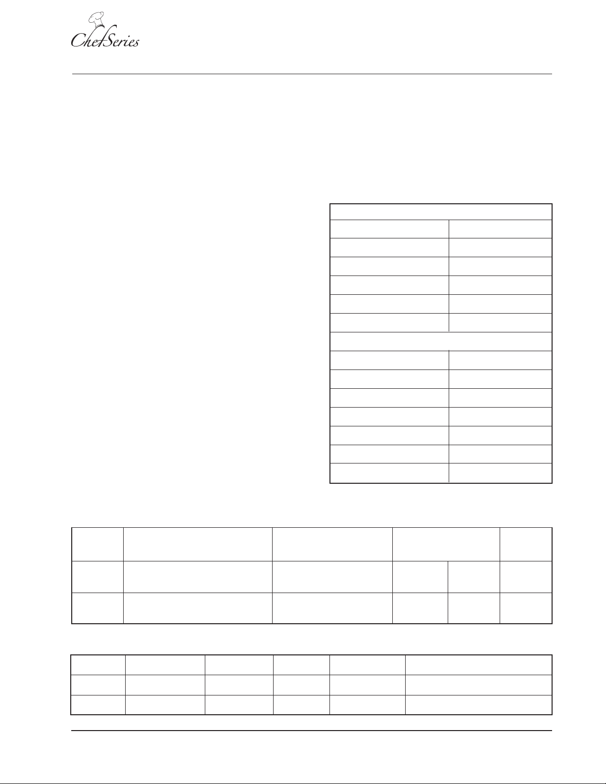
SPECIFICATIONS
Model Height × Width x Depth Clearance From Weight Freight
Combustible Surfaces Installed Shipping Class
GCSF-1 36″ × 40″ × 40″ Side:0″, Back:1″, Floor:4″ 555 lbs. 620 lbs. 70
(91.4cm × 101.6cm × 101.6cm) (252 kg) (281 kg)
GCSF-2 74″ × 40.4″ × 40″ Side:0″, Back:1″, Floor:4″ 1110 lbs. 1240 lbs. 70
(188cm × 102.6cm × 101.6cm) (503 kg) (562 kg)
UTILITY REQUIREMENTS
Model Voltage Total kW Phase Amps/Line Total Gas Req.
GCSF-1 120V/60Hz 0.7 1 5.8 1/2" NPT, 60,000 BTU/hr
GCSF-2 120V/60Hz 1.4 1 11.6 1/2" NPT , 120,000 BTU/hr
Lang A Division of S tar Mfg. Int'l Inc.
SM-5
Page 6
Service Manual for Enviro-Star GCSF-ES
DESCRIPTION
CONVECTION OVEN BASICS
A convection oven is an electro-mechanical, sealedtype of oven in which the combustion products are
separated from the air inside the oven. Heated air is
circulated by a fan into the oven and over the food
product, removing a thin layer of moisture from the
food and allowing heat to penetrate.
This method requires shorter cooking times at
lower temperatures and produces consistent results,
which may vary due to differences in preparation
rather than in oven operation.
Steam in the cooking process prevents the removal
of all the moisture during baking and produces a
better product. And when applied to bread dough
during the first five minutes, it allows yeast to work
longer producing better spring and volume and a
moist, flexible outer surface. Once the outside
layer of dough sets, gases in the loaf no longer
expand to increase loaf size.
Steaming bread dough as it bakes gelatinizes
starch on the outer layer and prevents the crust
from cracking. However, too much steam results in
an undesirable crust. During the last stages of
baking, a dry oven is needed to produce a crisp,
brown crust.
COMPONENT OPERATION
Electrical Power Circuit
The operating voltage (120 VAC) is routed from the
power source to a terminal block.
NOTICE: See the wiring diagrams in the
Troubleshooting section.
The AC line is connected through a 15 Amp fuse
(F7) to a contact on the motor relay (MR2), interior
light relay (LR1), and the primary winding of a stepdown transformer (T1).
The transformer provides 24 VAC through the circuit
board to control the oven electrical components.
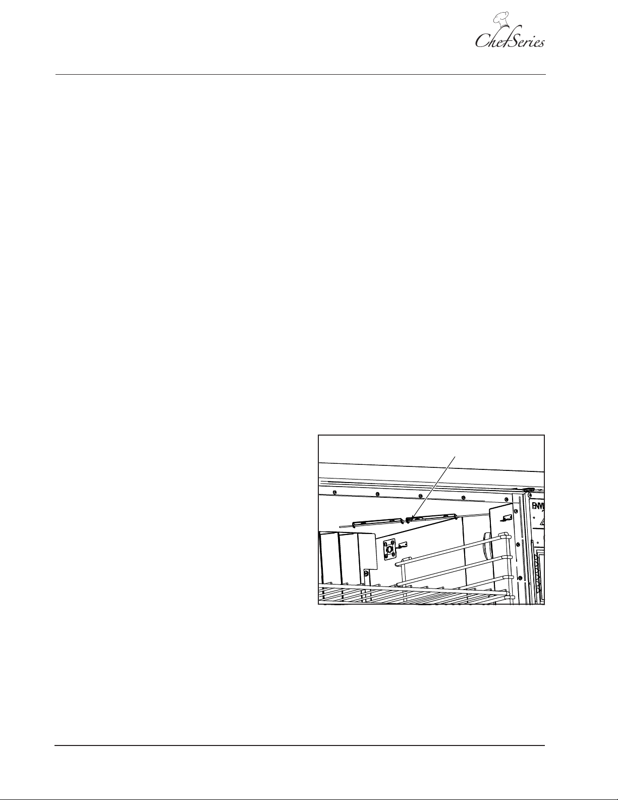
Thermostat Operation
The thermostat maintains oven temperature at the
desired setting. A sensor (Figure 1) mounted inside
the oven monitors oven temperature. The unit is
equipped with both:
• a mechanical thermostat
• a programmable temperature controller.
Times and temperatures may vary due to factors
such as food quality and quantity, type of pan and
thermostat calibration. Differences in altitude will
also affect cooking times and temperatures.
Time & Temperature Conversion: To convert
standard oven recipes for use in a convection oven,
reduce cooking temperature by 25° F – 75° F and
the time by 25% – 35%.
Fan Speeds: The convection fan can be set for HI
or LOW speed. Most baking is done on HI, but
delicate products (i.e., Meringue pie) require a
LOW fan setting.
Oven Sensor
Figure 1: Oven Sensor
When the operator selects a temperature setting or
the product to bake, the oven is heated until the
temperature reaches the selected setting. The
controls circuit monitors the temperature sensor
and activates the ignition control module to ignite
the burner when heat is required.
SM-6
Lang A Division of S tar Mfg. Int'l Inc.
Page 7
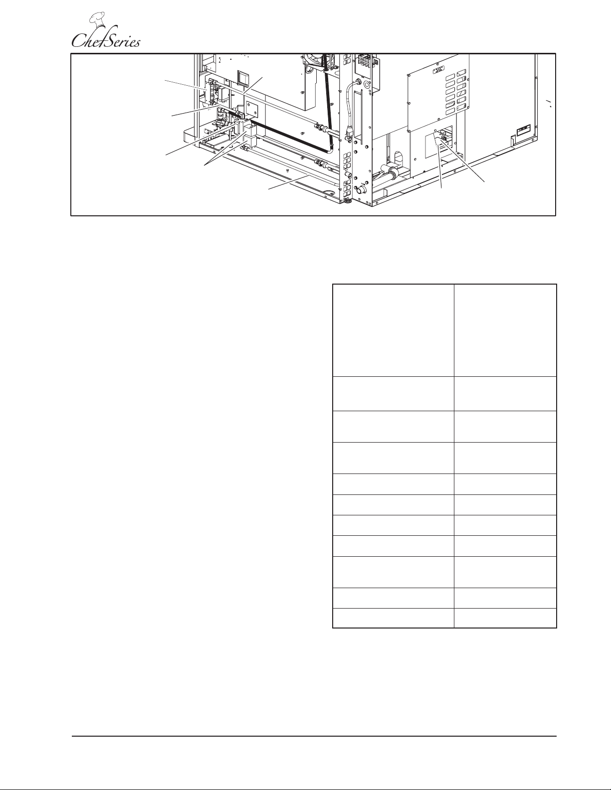
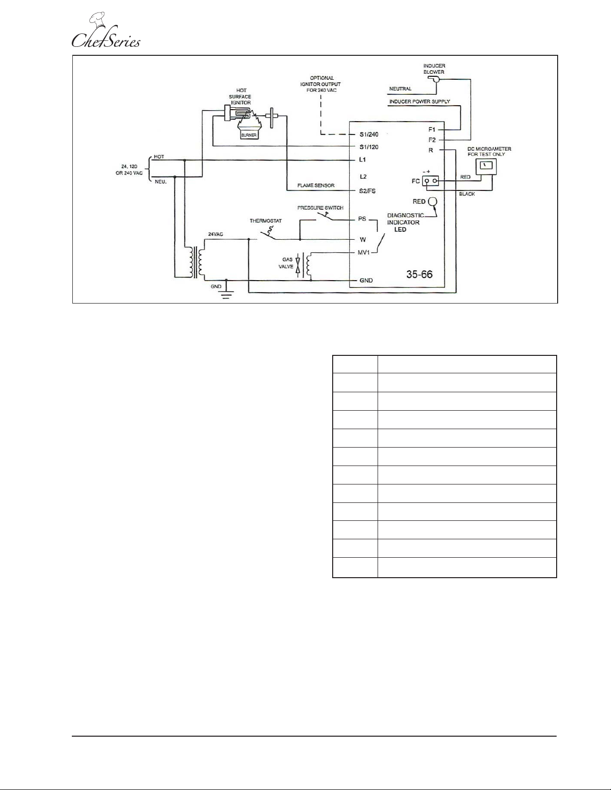
Figure 2: Gas Flow Diagram
Igniter &
Flame
Sensor
Burner
Gas Inlet
Line
Manual Gas
Valve
Burner Gas
Line
Solenoid
Valves
Main Gas
Valve
Intermediate
Gas Line
Service Manual for Enviro-Star GCSF-ES
Gas Flow and Ignition
Natural gas is supplied through the manual gas
valve (Figure 2) to the main gas solenoid. When the
temperature is selected the ignition control module
activates the igniter and opens the gas solenoid.
Gas flows to the burner and the igniter lights the
flame. The ignition control module monitors the
flame sensor to determine if the burner is on. If the
burner does not ignite, the solenoid valve closes
shutting off gas flow to the oven.
Ignition System
The igniter module controls ignition of the burner
gas. The module monitors burner ignition, heat and
shut down.
SPECIFICATIONS:
Fenwal 35-66 Series Igniter Module
INPUT POWER
Voltage
Current
OUTPUT POWER
Gas Valve 2.0A max @ 24 V AC
OPERATING TEMPERA TURE -40°F to +175°F
FLAME SENSITIVITY 0.7 micro amps
IGNITER 24 VAC
Trail for Ignition 7 Seconds
Inter-Purge 15 Seconds
Control: 18 to 30
VAC 50/60 HzLine:
24 VAC
300 MA @ 24 V A C
with fan and gas
valve relay energized
(-40°C to +80°C)
(minimum)
Lang A Division of S tar Mfg. Int'l Inc.
Pre-Purge 15 Seconds
Tries for Ignition 3 Tries with 1 Hour
Automatic Reset
Post Purge None
Options None
NOTE: Follow the wiring diagram and gas flow chart
to better understand the ignition description.
SM-7
Page 8
Service Manual for Enviro-Star GCSF-ES
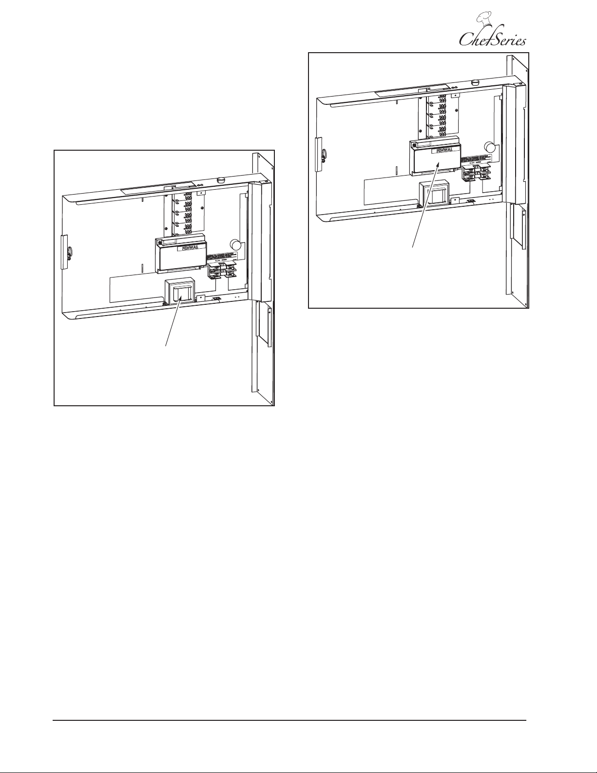
The oven ignition and control system operates on
120 and 24 VAC. When the power switch is placed
in the ON position, 120 VAC is routed through fuse
F7 (15A). The voltage from the fuse is routed to one
side (incoming) of a 24 VAC transformer (Figure 3).
The other side of the transformer (incoming) is
connected to a neutral input.
Ignition
Controller
Transformer
Figure 3: Transformer
The transformer converts the 120 VAC to 24 VAC
and routes the 24 VAC through the outgoing side
through a back-up switch, a back-up thermostat
switch and an over-temperature switch to the ignition
controller pin W.
The ignition control module (Figure 4) operates
on 24 VAC at pin W provided by the transformer.
The module controls the main gas solenoid and
the igniter.
Figure 4: Ignition Control Module
When the power switch is placed in the ON position
and a temperature is selected using the temperature
knob a call for heat is generated in the controller.
• The controller performs a self check routine.
• The diagnostic LED flashes for one second.
• A safety timing sequence begins.
• The controller performs a 15-second pre-purge of
the system.
• The controller must detect that the air switch is
working properly, before it energizes the igniter
and the surface of the igniter tip heats up.
• The main gas valve solenoids open allowing gas
to flow to the burner.
• The gas in the burner is ignited by the igniter tip.
A TFI (trail for ignition) period checks the flame sensor
for evidence of a flame at the burner. If flame does
not ignite within 7-seconds the control module closes
the main gas valve solenoids and gas stops flowing to
the burner.
SM-8
When a flame is detected, voltage to the igniter
stops and the igniter cools. The thermostat, pressure
switch and burner flame are monitored for proper
operation. When the selected temperature is reached
voltage stops flowing to the main gas valve solenoids
(Figure 5) and gas stops flowing to the burner.
Lang A Division of S tar Mfg. Int'l Inc.
Page 9
Service Manual for Enviro-Star GCSF-ES
Figure 5: Igniter Controller Diagram
If flame is not detected during the TFI, the main gas
valve solenoids close and a 15-second inter-purge
delay starts. The control will attempt two additional
TFI periods before locking out. In lockout the main
gas valve solenoids will be locked out immediately.
The controller will reset after one hour if the
thermostat is still calling for heat. A new TFI
sequence will begin.
NOTE: If locking out occurs, a manual reset must
be performed by resetting the thermostat or
removing 24 VAC (turn off the power switch) for a
period of 5-seconds.
The following table lists the igniter terminals and
functions.
NOTE: See the Troubleshooting section for
instructions on performing a flame sensor current
check.
./4%
3EE THE
TROUBLESHOOTING
SECTION FOR
INSTRUCTIONS ON
PERFORMING A
FLAME SENSOR
CURRENT CHECK
Igniter Module Terminal Uses (Figure 5)
S1 Igniter Output – 24 V AC
L1 24 VAC Input
L2 Not Used
S2 Flame Sensor Input
PS Air Proving Switch
W Thermostat Input
MV1 Main Gas Valve Solenoids Output
GND Ground Input
F1 120 VAC Input
F2 120 VAC Fan Drive Output
FC Not Used
R 24V Hot to Transformer
Lang A Division of S tar Mfg. Int'l Inc.
Fan Operation
The fan switch has two settings: HI and LOW. The
fan is mounted inside the oven and must be ON
when the oven is in operation. The main burner
heats the oven through the burner box. The main
burner flames do not come into contact with the air
inside the oven. The fan circulates the air inside the
oven over the lower surface and maintains a constant,
even temperature. The motor control reverses the
direction of the fan periodically to provide consistent
baking operation.
SM-9
Page 10
Service Manual for Enviro-Star GCSF-ES
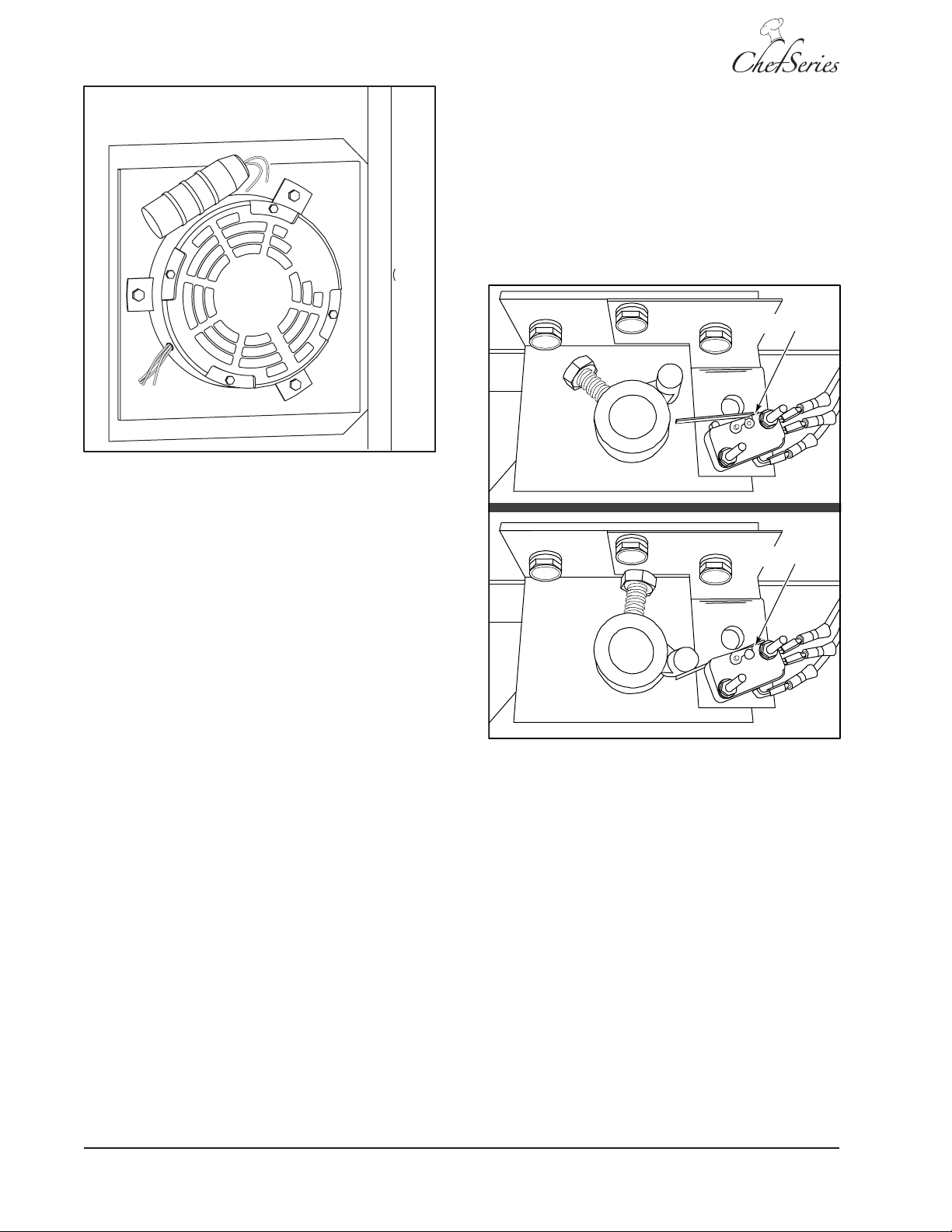
Door Switch Operation
When the oven door is closed, the door switch
(Figure 7) grounds four motor relays: MR2, the
ignition control module, the gas solenoid, and the
igniter. When the door is open, the ground is
removed and the fan motor and gas to the burner
shuts off. When the door is open, the ignition
control module and igniter cannot operate.
Door Switch
Figure 6: Fan Motor Connections
The fan motor (Figure 6) operates on 120 VAC.
Three relays operate on 24 VAC control motor.
The relays function as follows:
• Motor relay 1 (MR1) ON/OFF controls fan rotation
by reversing the phase of the motor windings.
• Motor relay 2 (MR2) ON/OFF controls motor
operation by routing 120 VAC to the fan motor.
• Motor relay 3 (MR3) ON/OFF controls fan speed
by routing 120 VAC to the motor windings.
DOOR OPEN
Door Switch
DOOR CLOSED
Figure 7: Door Open/Closed
SM-10
Lang A Division of S tar Mfg. Int'l Inc.
Page 11
Oven Lights
Service Manual for Enviro-Star GCSF-ES
Water (Steam) Applications
Light relay (LR1) routes voltage to one side of the
four oven lights (Figure 8). The other side of the
lights is connected to a neutral. When the
controller applies 24 VAC to the light relay, 120
VAC is routed to the oven lights, illuminating the
oven cooking area.
2YHQ/LJKWV
When steam is required for the baking process, the
controller activates the water solenoid (SV1)
(Figure 9). Water is passed through the water stall
(Figure 10) and heated to produce steam. The steam
fills the cooking area. The water system has a 3/8″
inlet line and a 3/8″ supply line to the water stall. The
water stall drain is 3/4″ allowing excess water to drain
quickly from the water stall.
6WHDPHU
$VVHPEO\
Figure 8: Oven Lights
Water
Outlet
Water
Solenoid
Water Inlet
Line
Water Stall
Figure 9: Water Flow Diagram
Lang A Division of S tar Mfg. Int'l Inc.
Line
Drain
Figure 10: Steamer Assembly (Water Stall)
Burnt Gas Exhaust
When natural gas is burned in the appliance, the
burnt gases must be vented away from the appliance.
The gases are exhausted out a vent and through a
flue (chimney or exhaust vent). There are numerous
exhaust/vent systems available to carry the exhaust
gases away from the appliance and work area.
WARNING
BURNING NATURAL GAS PRODUCES EXHAUST
GASES THAT CONTAIN CARBON MONOXIDE.
CARBON MONOXIDE IS A DEADLY GAS THAT
KILLS. ENSURE THAT APPLIANCE EXHAUST
VENTS, FLUES AND CHIMNEYS ARE
INSTALLED AND SERVICED BY PROFESSIONAL
INSTALLATION PERSONNEL AND ARE
ADEQUATE FOR THE APPLIANCE BEING
INSTALLED.
SM-11
Page 12
Service Manual for Enviro-Star GCSF-ES
T
A negative pressure in the appliance allows the
exhaust gases to flow up the flue. The flue helps
generate air flow around the burner, allowing the
burner to burn the gas more efficiently. A draft
inducer (Figure 11) provides air to the burner and
helps exhaust the burnt gasses.
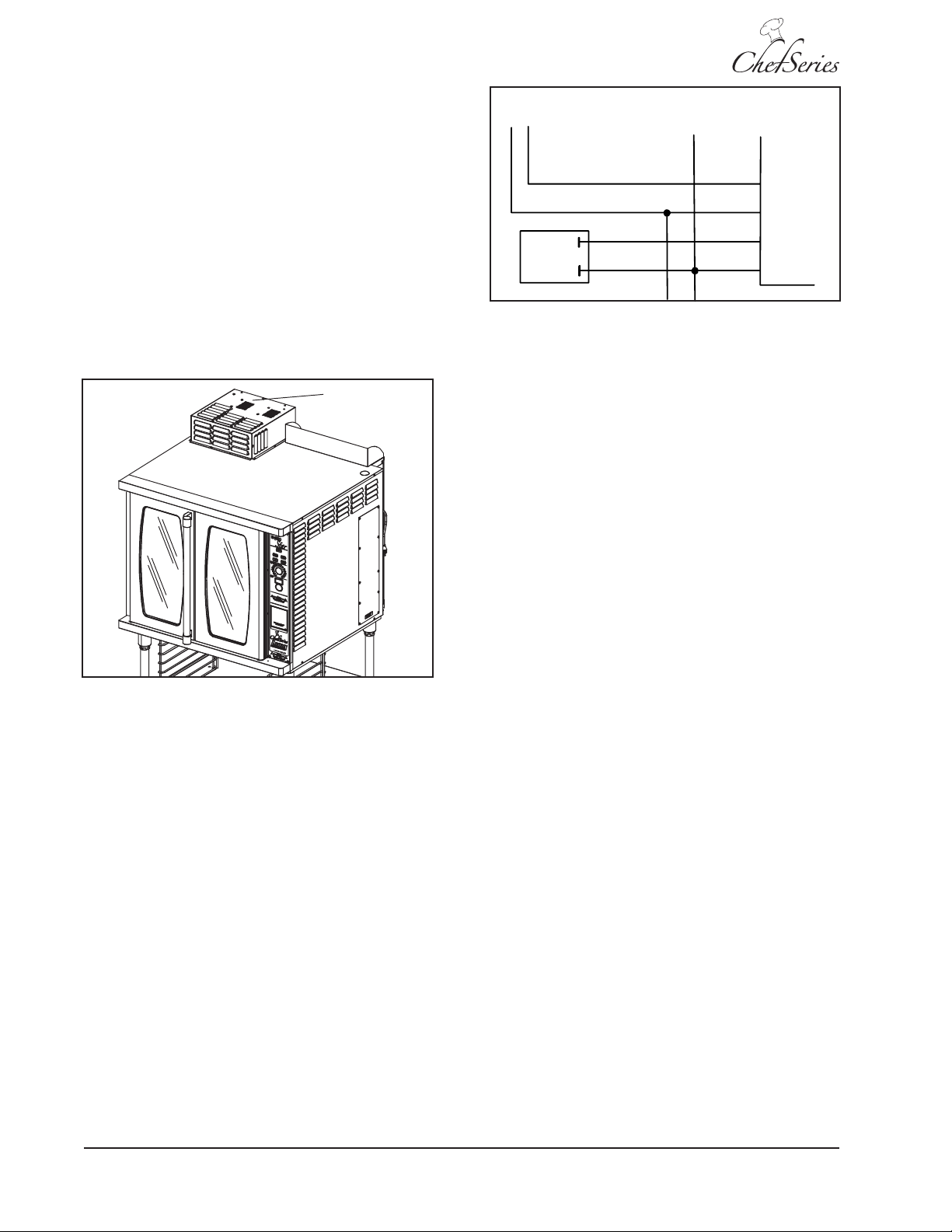
Draft Inducer Operation
The Draft Inducer is a device mounted on the top
of the oven over the exhaust vent. It provides
secondary air to the burners by creating a draft. The
operation of the Draft Inducer is controlled by the
Ignition Control.
Draft Inducer
O AIR PROVIN G
SWITCH
PS
54
W
37
55
34
MV1
GND
GAS
VALVE
37
55
34
Figure 12: Igniter Controller Internal Switch
During oven operation, combustion air flow is
monitored by the proving switch (pressure switch).
If the switch contacts remain closed for 30-seconds
during ignition sequence without an output signal to
the draft fan an airflow fault will be generated. If the
pressure switch (proving switch) contacts open
during a call for heat operation, the controller
(Figure 12) will begin a pre-purge period and a trail
for ignition sequence.
Figure 11: Draft Inducer
NOTE: See the wiring diagram for wire routing for
the draft inducer.
The draft inducer uses a proving switch to ensure
proper air flow when the burner is in operation. The
switch is mounted between the controller W terminal
and the PS terminal. An internal controller switch
(Figure 12) between the PS and MV1 terminals,
routes voltage to the main gas valve. If the internal
switch is open, the main gas valve solenoid will not
open to allow gas flow to the burner.
NOTE: In a description of the draft inducer, the
pressure switch is often referred to as a proving
switch. The terms mean the same thing and both
refer to the switch monitoring the draft inducer
air flow.
If the pressure switch (proving switch) contacts
remain open for 30-seconds after draft inducer fan
output (F1 and F2) begins, an airflow fault will be
signaled and the fan will remain ON. If the pressure
contacts open later during a call for heat, the
controller will begin a pre-purge period and the trail
for ignition sequence.
If the airflow signal (PS) is lost while the burner is
firing, the controller will immediately de-energize
the main gas valve solenoid and an airflow fault will
be displayed. The controller will continue to monitor
the proving switch (pressure switch) input waiting
for airflow to return. When airflow is detected, a trail
for ignition sequence will begin, followed by a prepurge period. If airflow does not return, the controller
will enter a lockout condition and the draft inducer
fan will shut OFF.
During normal sequence, if a flame signal occurs
due to the main gas valve solenoid not closing all
the way, the controller will energize the draft inducer
fan. If the gas valve solenoid closes, the controller
will shut off the draft inducer fan.
SM-12
Lang A Division of S tar Mfg. Int'l Inc.
Page 13
CONTROLS
Service Manual for Enviro-Star GCSF-ES
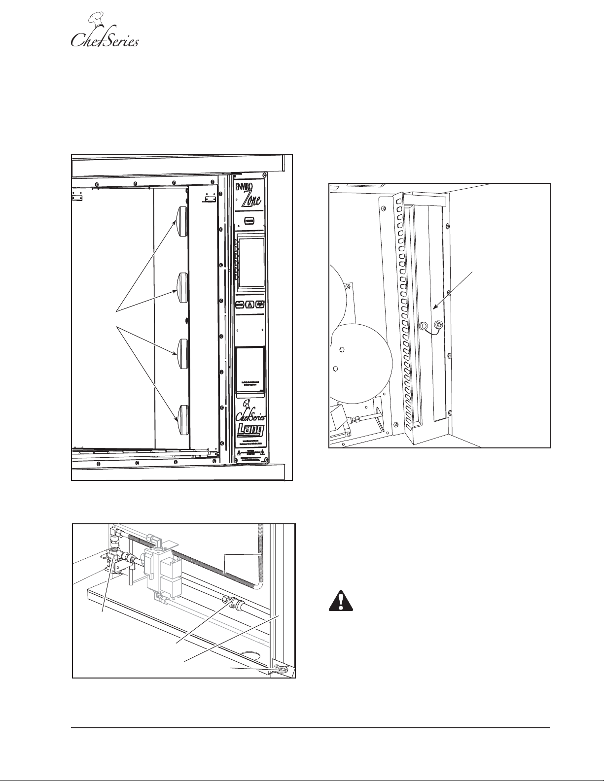
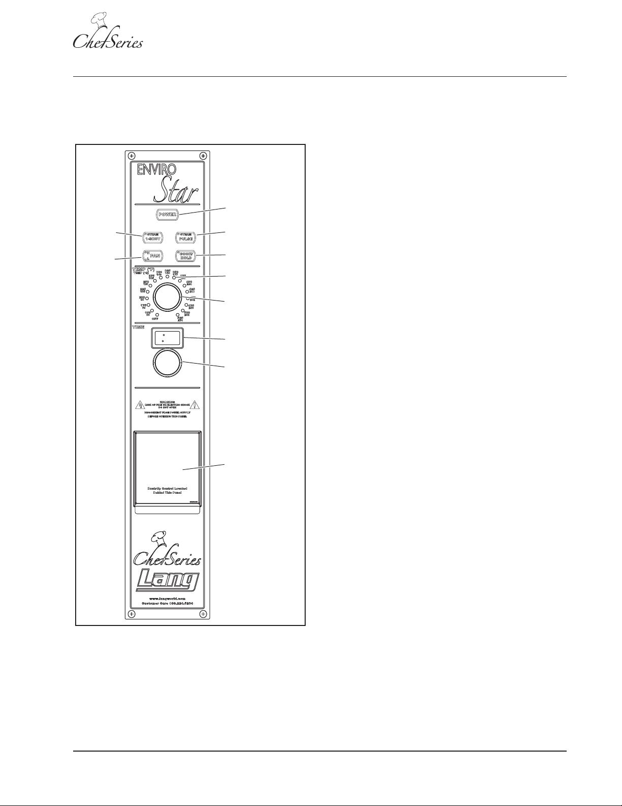
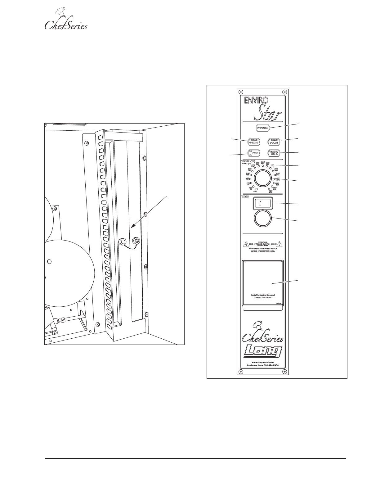
The electronic control panel (Figure 13) is used to
control oven operation. The unit also has manual
backup controls.
Power
1-Shot
Steam
Fan
HI/LOW
Pulse Steam
COOK-N-HOLD
LED Temp
Indicator
Temp Knob
LED Timer
Screen
Timer Knob
Electronic Control Panel (Figure 13)
POWER:
• ON/OFF button
• When pressed ON, interior lights and panel
indicators turn on
• When pressed OFF, interior lights and panel
indicators turn off and the fan remains ON until
the oven cools down to 250° F
FAN:
• ON/OFF Switch
• Has two operating speeds: L=LOW & H=HI
• Must be turned on during operation
• During operation, the fan will reverse directions
periodically to maintain consistent condition
LED TEMPERATURE INDICATOR:
• Displays oven temperature
• ON indicates oven at set point
• Blinks with a call for heat or cooling to temperature
BACKUP
CONTROL
ACCESS DOOR
Figure 13: Electronic Control Panel
TEMPERATURE KNOB:
• Used to set oven temperature
• Dial to desired temperature
TIMER SCREEN:
• LED digital display
• Displays time remaining in cooking cycle
• Displays time selection for Steam Pulse
• Displays time selection for Steam 1- Shot time
TIMER KNOB:
• Sets cooking time
• Sets Steam Pulse time
• Sets Steam 1-Shot time
COOK/HOLD:
• Activated when cooking cycle stops and a
beeper will sound 5 times
• Beeper will sound 5 times
• COOK/HOLD light will turn OFF
• Oven temperature will drop to 150° F
• Temperature will remain at 150° F until operator
chooses a new cooking cycle or turns the oven
OFF
Lang A Division of S tar Mfg. Int'l Inc.
SM-13
Page 14
Service Manual for Enviro-Star GCSF-ES
1-SHOT STEAM:
Initial Power ON Test
• Provides a 1 – 20 second single–shot of steam
to the cooking chamber
• Adjust by holding down the button while turning the
TIMER KNOB until the desired time is displayed on
the LED TIMER SCREEN (Figure 13)
PULSE STEAM:
• Sends a 1-second shot of steam to the cooking
chamber
• Adjust time from 1 – 120 seconds by holding
down the button and turning the TIMER KNOB
until the desired time is displayed on the LED
TIMER SCREEN
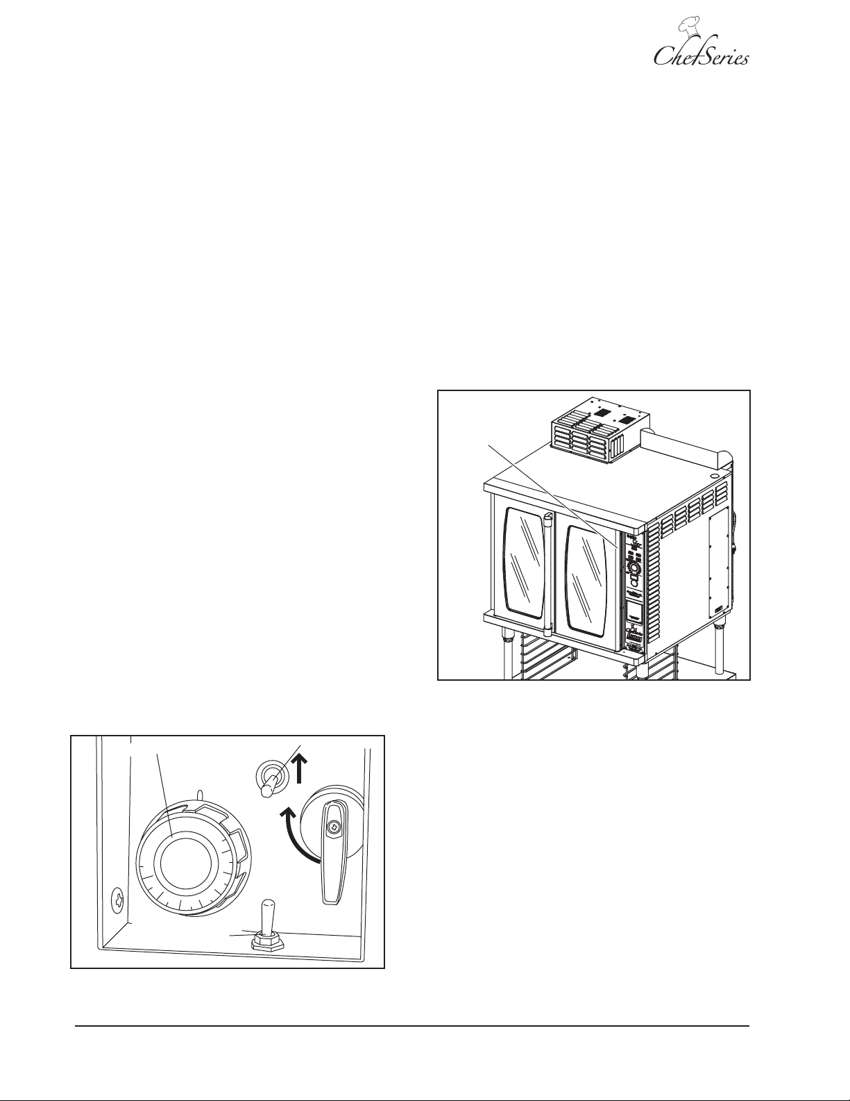
Using Backup Controls
The EnviroSTAR oven is designed with a set of
backup controls that can be used manually instead
of using the electronic oven controls. These controls
(Figure 14) are mounted behind a door below the
oven control panel (Figure 13). Controls include the
BACKUP/MANUAL switch, a TEMPERATURE knob
and a STEAM switch.
Follow these steps to verify the operation and
temperature control of the oven:
• Press the POWER button ON and verify that
the interior and panel lights turn on.
• Set the temperature to 300°F and verify that the
TEMP INDICATOR light is blinking.
• Verify that the oven reaches the set point and
signals Ready with an audible tone within 12
minutes (starting with a cold oven).
• Set the timer to 10 minutes and verify that the
fan stops and reverses direction after
approximately 108 seconds. (A full reversing
cycle takes 120 seconds.)
Door Switch
The BACKUP/MANUAL switch overrides the electronic
controls and activates the backup controls. The
TEMPERATURE knob controls the temperature. The
STEAM toggle switch controls the steam. In this
mode, the fan will operate at HI speed only.
The Backup mode does not use the energy-saving
option and does not allow the fan to operate at Low
speed or reverse direction.
To use the backup controls, place the BACKUP/
MANUAL switch in the BACKUP position.
Temperature Knob
TEMP
OFF
100
150
200
250
Backup / Electronic
Controls Switch
STEAM
450
400
350
300
Steam Switch
G
A
S
S
H
U
T
O
F
F
Figure 15: Door Switch Location
• Open the oven door (Figure 15) and verify that
the fan and TIMER stop then restart when the
door is closed.
• Turn both the TIMER KNOB and TEMP KNOB
to zero.
• Confirm that the fan stays on until the
temperature drops below 250°F.
SM-14
Figure 14: Backup Controls
Lang A Division of S tar Mfg. Int'l Inc.
Page 15
Water/Steam Test
Power
Pulse Steam
COOK-N-HOLD
1-Shot
Steam
Fan
HI/LOW
LED Temp
Indicator
Temp Knob
LED Timer
Screen
Timer Knob
BACKUP
CONTROL
ACCESS DOOR
Service Manual for Enviro-Star GCSF-ES
Operating Sequence
Follow these steps to verify the water and steam
operation of the oven:
1. Identify the water purification system used.
2. Flush the water system to remove tainted
water from the system.
3. Put the oven into Backup mode and set the
temperature to 400°F.
6WHDPHU
$VVHPEO\
NOTE: Refer to the Lang™ GCSF-ES/GCSF-EZ
Installation and Operation Instructions for full
operational description, including optional features.
Figure 16: Water/Steam System (Water Stall)
4. Once up to temperature, use the STEAM
SWITCH on the control panel (Figure 17) to
flush water through the steam system (water
stall) (Figure 16) for one minute.
5. Check the water drain for proper operation.
Figure 17: Electronic Control Panel
Lang A Division of S tar Mfg. Int'l Inc.
SM-15
Page 16
Service Manual for Enviro-Star GCSF-ES
The following table lists typical operating sequences
in order and results.
Operating Sequence
ACTION RESUL T
Power button pressed ON Panel lights and interior
lights illuminate.
HI or LOW fan speed selected HI or LOW fan speed light
illuminates.
TEMP KNOB used to select Oven begins heating and
125° F – 525° F fan begins air circulation.
NOTE: The minimum NOTE: The fan will
temperature for steam reverse direction every
operation is 125° F. two minutes during the
cooking process.
STEAM PULSE button pressed STEAM PULSE light
while selecting a steam pulse illuminates, TIMER LED
time from 1 – 120 seconds momentarily displays
pulse time and steam
pulse is applied.
Set temperature reached Buzzer sounds eight
within 12 minutes times.
Product loaded into oven Product begins to bake.
TIMER used to set cooking Cook time displays on
time LED and countdown
begins.
NOTE: If the steam pulse
is used, a one-second
shot of steam is applied
to the baking area.
Optional COOK/HOLD button COOK/HOLD light
pressed illuminates.
Set cooking time expires Five-beep tone
sounds.
NOTE: If COOK/HOLD is
used, the oven
temperature will drop to
150° F , the COOK/HOLD
light will turn OFF and the
oven will maintain at
150° F until the oven is
turned OFF or a new
cooking cycle is started.
Product removed from oven Oven is ready for
cooking.
SM-16
Lang A Division of S tar Mfg. Int'l Inc.
Page 17
MAINTENANCE
Service Manual for Enviro-Star GCSF-ES
CAUTION
Always keep clear of combustible materials.
CAUTION
Keep the floor in front of equipment clean and
dry. If spills occur, clean immediately to avoid
the danger of slips or falls.
• Water filters and conditioners should be
inspected and replaced per manufacturer’s
recommendations.
OVEN CLEANING
Exterior
See STAINLESS STEEL CARE AND CLEANING.
Interior
WARNING
KEEP WATER AND SOLUTIONS OUT OF THE
CONTROLS AREA. NEVER SPRAY OR HOSE
THE CONTROL PANEL.
CAUTION
Most cleaners are harmful to the skin, eyes,
mucous membranes and clothing. Precautions
should be taken to wear rubber gloves, goggles
or a face shield and protective clothing.
CAUTION
Do not use caustic cleaners.
• Always start with a cold oven.
• Always follow the oven cleaner instructions.
• Do not use caustic cleaners. Using any harsh
chemicals will result in removal of the ETC
coating and etching of the porcelain.
• The oven interior should be cleaned using mild
soap and a non-metal scouring pad.
• Care should be taken to prevent caustic cleaning
compounds from coming in contact with the fan
wheel.
• Oven interior should be wiped down daily and
thoroughly cleaned weekly using warm water
and mild detergent. Do not use caustic cleaners.
• This appliance should be checked at six-month
intervals by a qualified technician (heating unit,
mechanical stability, corrosion, etc.), especially
control and safety devices.
• The oven racks and rack slides may be removed
and cleaned outside the oven using oven cleaner.
• The stainless exterior can easily be cleaned
using stainless steel cleaner.
• Always apply stainless steel cleaners when
the oven is cold and rub in the direction of the
metal’s grain.
CAUTION
Carefully read all warnings and follow the
directions on the label of the cleaner to be used.
CAUTION
Never leave a chlorine sanitizer in contact with
stainless steel surfaces longer than ten minutes.
Prolonged contact can cause corrosion.
Lang A Division of S tar Mfg. Int'l Inc.
SM-17
Page 18
Service Manual for Enviro-Star GCSF-ES
STAINLESS STEEL CARE
Cleaning
Stainless steel contains 70-80% iron, which will
rust if not properly maintained. It also contains 1230% chromium, which forms an invisible passive,
protective film that shields against corrosion. If the
film remains intact, the stainless steel will remain
intact. However, if the film is damaged, the stainless
steel can break down and rust. To prevent stainless
steel breakdown, follow these steps:
CAUTION
Never use any metal tools. Scrapers, files, wire
brushes or scouring pads (except for stainless
steel scouring pads) will mar the surface!
CAUTION
Never use steel wool, which will leave behind
particles that rust!
CAUTION
Never use acid-based or chloride-containing
cleaning solutions, which will break down the
protective film!
Preserve the life of stainless steel with a regular
application of a high quality stainless steel polishing
cleaner as a final step to daily cleaning.
If signs of breakdown appear, restore the stainless
steel surface. First, thoroughly clean, rinse and dry
the surface. Then, on a daily basis, apply a highquality stainless steel polish according to
manufacturer’s instructions.
Heat Tint
Darkened areas, called heat tint, may appear on
stainless steel exposed to excessive heat, which
causes the protective film to thicken. It is unsightly
but is not a sign of permanent damage.
To remove heat tint, follow the routine cleaning
procedure. Stubborn heat tint will require heavyduty cleaning.
To reduce heat tint, limit the exposure of equipment
to excessive heat.
LOCKOUT/TAGOUT PROCEDURES
This section of the manual describes removal and
replacement of the various parts available from an
authorized service provider. For part numbers, refer
to the exploded view parts list in the Operations
Manual provided with the unit.
CAUTION
Never rub in a circular motion!
CAUTION
Never leave any food products or salt on the
surface. Many foods are acidic. Salt contains
chloride!
For routine cleaning, use warm water, mild soap or
detergent and a sponge or soft cloth.
For heavy-duty cleaning, use warm water, a
degreaser and a plastic, stainless steel or ScotchBrite pad.
Always rinse thoroughly. Always rub gently in the
direction of the steel grain.
Preserving & Restoring
Special stainless steel polishing cleaners can
preserve and restore the protective film.
Electrical Lockout/Tagout
The Lockout/Tagout procedure is used to protect
personnel working on an electrical appliance.
Perform the following steps when performing any
type of maintenance or service on an electrically
operated appliance.
1. In electrical box, place unit’s circuit breaker
into OFF position.
2. Place a lock or other device on electrical box
cover to prevent someone from placing circuit
breaker ON.
3. Place a tag on electrical box cover to indicate
that unit has been disconnected for service and
power should not be restored until tag is removed
by maintenance personnel.
4. Disconnect unit power cord from electrical
outlet.
5. Place a tag on cord to indicate that oven has
been disconnected for service and power should
not be restored until tag is removed by
maintenance personnel.
SM-18
Lang A Division of S tar Mfg. Int'l Inc.
Page 19
Gas Lockout/Tagout
Service Manual for Enviro-Star GCSF-ES
Electronics Access
The Gas Lockout/Tagout procedure is used to
protect personnel working on a gas appliance.
Before performing any type of maintenance or
service on a gas appliance, follow these steps:
1. Locate the natural gas or inlet valve and place
the valve in the OFF position.
2. Place a tag on the valve indicating that service
is being performed on equipment and the natural
gas must remain off until service is complete by
the maintenance personnel.
3. Place a locking device on the natural gas inlet
valve preventing actuation until the lock is
removed by the maintenance personnel.
4. On the appliance, make sure all flame sources
are extinguished and/or removed by
maintenance personnel.
5. Bleed residual gas from the appliance inlet line
and allow time for the gas to dissipate before
beginning service on the appliance.
Gas Leak Test
WARNING
PERFORM THE ELECTRICAL
LOCKOUT/TAGOUT
PROCEDURE.
1. Perform the Electrical Lockout/Tagout
procedure, found on page 18 of this manual..
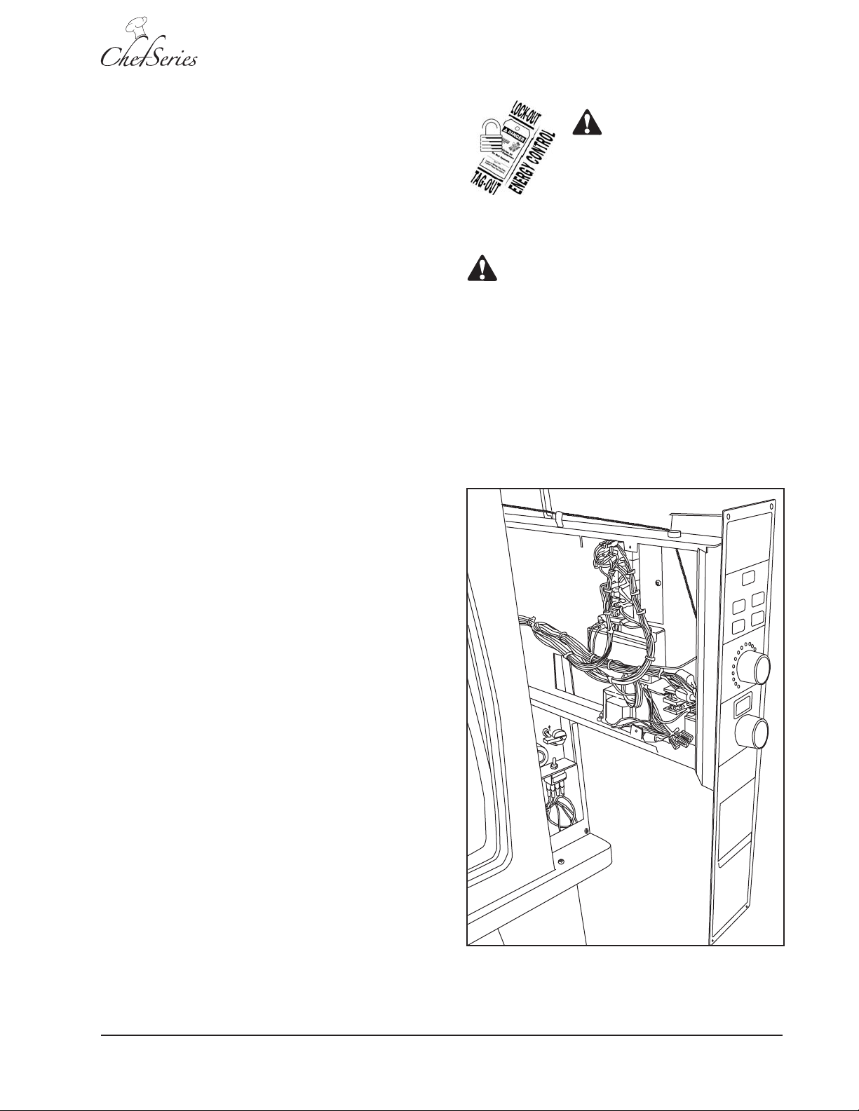
CAUTION
In the following steps, the upper and lower edges
of the electronics drawer slide in and out of the
mounting brackets. DO NOT pull the drawer
completely out from the oven, as it could slip out
and damage wiring and/or other components. If
further access to the drawer area is needed,
perform the External Right Side Panel Removal
procedure.
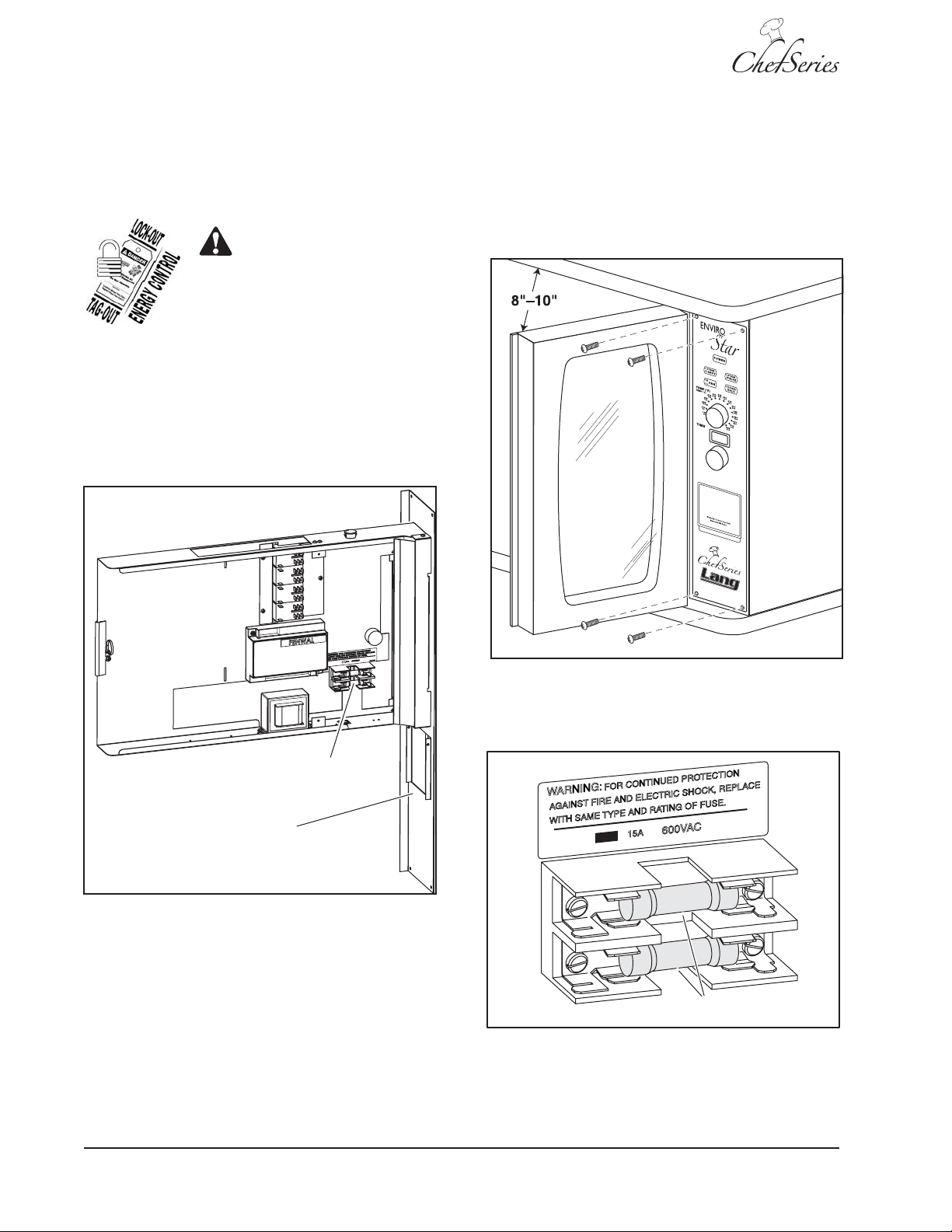
2. Open the oven doors approximately eight to ten
inches.
After completing service on any natural gas
appliance, all gas joints disturbed during service
must be check for leaks. DO NOT USE AN OPEN
FLAME. Use a hazardous gas tester or a soap and
water solution.
1. Apply a soap and water solution to gas joint and
check for bubbles.
2. If bubbles are present, the joint is leaking and
must be repaired before using the appliance.
Lang A Division of S tar Mfg. Int'l Inc.
Figure 18: Electronics Drawer
SM-19
Page 20
Service Manual for Enviro-Star GCSF-ES
WARNING:
FO
R CONTINUED PROTECTION
AGAINST FIRE AND ELECTRIC SHOCK, REPLACE
WITH SAME TYPE AND RAT IN G OF FUSE.
600VAC
15A
60302-77
Fuse
3. Remove four screws located at the top and
bottom of the front panel.
7. Slide the electronics drawer closed, but do not
install mounting screws.
4. Carefully slide the electronics drawer
(Figure 18) out from the oven.
Main Power Fuse Replacement
WARNING
PERFORM THE ELECTRICAL
LOCKOUT/TAGOUT
PROCEDURE.
1. Perform the Electrical Lockout/Tagout
procedure, found on page 18 of this manual.
2. Perform the Electronics Access procedure.
3. Locate the fuse block (Figure 19) in the
electronics drawer (Figure 20).
8. Connect the oven to external power, and press
the front panel POWER button to ensure the
oven is operational.
9. When proper operation is determined, install
and tighten four mounting screws.
Fuses
Electronics
Drawer
Figure 19: Fuse Locator
4. Use an Ohmmeter to ensure the fuse is open
before replacing it. An ohm reading indicates
5. Using a fuse puller or similar tool remove the
the fuse has continuity and is good.
fuse.
6. Install an exact replacement fuse (Figure 21) in
the fuse holder. (Class G, Type SC-15, Time
Delay, rated for 600 VAC)
Figure 20: Electronics Drawer Access
Figure 21: Fuse Replacement
SM-20
Lang A Division of S tar Mfg. Int'l Inc.
Page 21

Circuit Board Replacement
Beeper
Keypad
Ribbon
Cable
Door
Open
Sensor
Temperature
Sensor
Output
Connector
WARNING
PERFORM THE ELECTRICAL
LOCKOUT/TAGOUT
PROCEDURE.
Service Manual for Enviro-Star GCSF-ES
NOTE: A spacer and two washers remain on each
mounting stud. Do not lose the washers and
spacers.
9. To install a replacement circuit board, carefully
insert the temperature selector and timer shafts
through the front panel and position the circuit
board on the four corner studs.
1. Perform the Electrical Lockout/Tagout
procedure, found on page 18 of this manual.
2. Perform the Electronics Access procedure.
3. Remove the heat shield on the right side front
(Figure 22) of the electronics drawer by removing
mounting screws at the top and bottom.
10. Secure the circuit board with nylon washers
and nuts but do not tighten nuts.
11. Secure the temperature selector and timer with
a washer and nut and tighten nut securely.
12. Install knobs on the temperature selector and
timer.
13. Tighten the circuit board nuts securely.
14. Using tags created during removal, connect five
cables to the circuit board.
15. Slide the electronics drawer closed but do not
install mounting screws.
16. Connect the oven to external power, and press
the panel POWER button ON to ensure the
oven is operational.
17. Secure the electronics drawer with four screws
and tighten screws securely.
18. Place the heat shield in position, secure with
two screws and tighten screws securely.
Heat Shield
Figure 22: Heat Shield
4. Tag and disconnect five cables (Figures 23 and
24) from the circuit board. DO NOT pull on the
wires!
5. Carefully pull off the knobs from the temperature
selector and timer.
6. Remove the mounting nut and washer from
temperature selector and timer shafts.
7. Remove the nuts and nylon washers from in the
four corners of the circuit board.
8. Carefully remove the circuit board from the
threaded studs.
Figure 23: Circuit Board Connectors
Lang A Division of S tar Mfg. Int'l Inc.
SM-21
Page 22

Service Manual for Enviro-Star GCSF-ES
Transformer
Beeper
Temperature
Output
Connector
Keypad
Ribbon
Cable
Door
Open
Sensor
Sensor
11. Connect the oven to external power, and press
the POWER button ON to ensure the oven is
operational.
12. Secure electronics drawer with four screws and
tighten screws securely.
Figure 24: Circuit Board Cables
Power Transformer Replacement
WARNING
PERFORM THE ELECTRICAL
LOCKOUT/TAGOUT
PROCEDURE.
1. Perform the Electrical Lockout/Tagout
procedure, found on page 18 of this manual.
2. Perform the Electronics Access procedure.
3. Remove two mounting screws from the wire
cover (Figure 25), pivot cover to the left and
remove.
4. Cut the ties securing transformer wires.
5. Remove two screws securing transformer
(Figure 26) to the drawer base.
6. Tag and disconnect transformer wires.
7. Position replacement transformer and secure
with two mounting screws.
&RPSRQHQW 7UDQVIRUPHU
:LUH&RYHU
Figure 25: Component Wire Cover Location
8. Using tags created during removal, connect
wires to the replacement transformer.
9. Secure the wiring with plastic ties.
10. Slide the electronics drawer closed but do not
install mounting screws.
SM-22
Figure 26: Transformer
Lang A Division of S tar Mfg. Int'l Inc.
Page 23

Beeper Removal
Relays
Service Manual for Enviro-Star GCSF-ES
Relays
WARNING
PERFORM THE ELECTRICAL
LOCKOUT/TAGOUT
PROCEDURE.
1. Perform the Electrical Lockout/Tagout
procedure, found on page 18 of this manual.
2. Perform the Electronics Access procedure.
3. Remove the beeper connector from the circuit
board (Figure 27).
Four 24 VAC relays are used to operate the relay
coil, which acts like a switch. The relays control the
circuits as follows:
Beeper
Figure 27: Beeper Location
4. While holding the beeper, remove the mounting
ring from the side of the drawer housing.
5. Install the new beeper and connect the cable
connector into the circuit board.
6. Slide the electronics drawer closed but do not
install mounting screws.
7. Connect the oven to external power and press
the POWER button ON to ensure the oven is
operational.
8. Secure electronics drawer with four screws and
tighten securely.
Figure 28: Relay Mounting
• Relay 1 – MR1 – Fan Motor Forward/Reverse
• Relay 2 – MR2 – Fan Motor Run
• Relay 3 – MR3 – Fan Motor HI/LOW Speed
• Relay 4 – LR1 – Light
Figure 29: Basic Relay Operation
Lang A Division of S tar Mfg. Int'l Inc.
SM-23
Page 24

Service Manual for Enviro-Star GCSF-ES
12 13 11
13 10
MOTOR
REL AY 1
(FWD/REV)
MOTOR
REL AY 2
(RUN)
MOTOR
REL AY 3
(HI/LO SPEED)
LIGHT
REL AY
LR1
20 19 21
21 24 20
15 10
32
41
35
34
32
48
32
42
Relay Operation
Relays use low voltage (Figure 29) to activate a
switch that routes a higher voltage to a component.
All four oven relays operate in the same manner.
One side of the coil (Figure 29) is grounded. When
activated by the control system (circuit board), 24
VAC is routed to the other side of the coil. With
ground and 24 VAC applied to the coil, a magnetic
field is generated. The magnetic field pulls the
switch down. The 120 VAC is then routed through
the switch to one side of the light bulb. Because the
other side of the light bulb is grounded, the bulb
illuminates.
3. Remove two mounting screws from the wire
cover (Figure 30), pivot the cover to the left and
remove.
4. Locate the relay (Figure 31) and remove the
screw and relay clamp on the right side.
5. Tag and disconnect wires from the relay.
6. Using tags created during removal, connect
wires to the relay.
7. Position the relay for installation.
8. Secure the relay with the clamp and screw.
9. Slide the electronics drawer closed but do not
install the mounting screws.
Relay Replacement
WARNING
PERFORM THE ELECTRICAL
LOCKOUT/TAGOUT
PROCEDURE.
1. Perform the Electrical Lockout/Tagout
procedure, found on page 18 of this manual.
2. Perform the Electronics Access procedure.
&RPSRQHQW 7UDQVIRUPHU
:LUH&RYHU
Figure 30: Wire Cover
10. Connect the oven to external power, and press
the POWER button ON to ensure the oven is
operational.
11. Secure the electronics drawer with four screws.
Figure 31: Relay Connections
SM-24
Lang A Division of S tar Mfg. Int'l Inc.
Page 25

Ignition Controller Replacement
Service Manual for Enviro-Star GCSF-ES
Right Side Panel Removal
WARNING
PERFORM THE ELECTRICAL
LOCKOUT/TAGOUT
PROCEDURE.
1. Perform the Electrical Lockout/Tagout
procedure, found on page 18 of this manual.
2. Perform the Electronics Access procedure.
3. Remove two mounting screws from the wire
cover (Figure 30), pivot the cover to the left and
remove.
4. Locate the ignition controller (Figure 32) in the
electronics drawer.
5. Remove mounting screws from the upper left
and lower right corners.
6. Tag and disconnect wires from the ignition
controller.
7. Position the new ignition controller and secure
with two screws.
The gas valves, water valves and connections are
mounted behind the right side panel.
CAUTION
Sheet metal edges can cut! Avoid bare hand
contact with metal edges. Wear protective gloves
during installation, operation, cleaning, and
maintenance.
WARNING
PERFORM THE ELECTRICAL
LOCKOUT/TAGOUT
PROCEDURE.
1. Perform the Electrical Lockout/Tagout
procedure, found on page 18 of this manual.
2. Remove four screws from the right side panel
(Figure 33) at rear of the oven.
Ignition
Controller
Figure 32: Ignition Controller
8. Using tags created during removal, connect
wires to the replacement controller.
9. Slide the electronics drawer closed, but do not
install mounting screws.
10. Connect the oven to external power, and press
the POWER button ON to ensure the oven is
operational.
Right Side
Panel
Figure 33: Right Side Panel
3. Remove the two screws from lower edge of the
right side panel.
4. Remove two screws from the upper edge of the
right side panel.
NOTE: The right side panel has a flange along the
top, bottom and rear.
5. Carefully slide the side panel back about ¾ inch
and straight down for removal.
6. To install right side panel, reverse above steps.
11. Secure the electronics drawer with four screws.
Lang A Division of S tar Mfg. Int'l Inc.
SM-25
Page 26

Service Manual for Enviro-Star GCSF-ES
Temperature Sensor Replacement
WARNING
PERFORM THE ELECTRICAL
LOCKOUT/TAGOUT
PROCEDURE.
1. Perform the Electrical Lockout/Tagout
procedure, found on page 18 of this manual.
2. Perform the Electronics Access procedure.
7HPSHUDWXUH
6HQVRU
3. Perform the External Right Side Panel Removal
procedure.
4. Disconnect the temperature sensor plug from
the circuit board connector (Figure 23) and pull
the tube through the grommet in the drawer.
2YHQ6HQVRU
Figure 34: Temperature Sensor Location
5. Grasp the sensor (Figure 34) near the entry into
the oven, push it out of the oven and into the
electronics drawer.
Figure 35: Temperature Sensor
12. Slide the electronics drawer closed but do not
install the mounting screws.
13. Connect the oven to external power, and press
the POWER button ON to ensure the oven is
operational.
14. Secure the electronics drawer with four screws.
Fan Motor Starter Capacitor Replacement
WARNING
PERFORM THE ELECTRICAL
LOCKOUT/TAGOUT
PROCEDURE.
1. Perform the Electrical Lockout/Tagout
procedure, found on page 18 of this manual.
2. Remove the motor access panel at the rear of
the oven.
WARNING
ELECTRICAL HAZARD THE CAPACITOR MAY
BE CHARGED.
6. Pull the sensor out of the oven wall and into the
electronics drawer.
7. Slide the tip of the new sensor through the oven
wall hole into the oven.
8. Slide the tip of the sensor through the holes and
into the mounting bracket until it protrudes ¾
inch from the end of the bracket.
9. Pass the temperature sensor tube (Figure 35)
through the grommet into the electronics drawer.
10. Attach the connector to the circuit board
(Figure 23).
11. To install all previously removed parts, reverse
the above steps.
SM-26
3. Remove the rubber boot covering the connectors
on the motor starting capacitor (Figure 36).
4. Discharge the capacitor.
5. Tag and disconnect wires from the capacitor.
6. Remove three screws securing the capacitor
mounting straps to the rear housing.
7. Remove mounting straps from the capacitor
and install onto the new capacitor.
8. Position the new capacitor for installation.
9. Secure the capacitor with three screws in the
mounting straps.
Lang A Division of S tar Mfg. Int'l Inc.
Page 27

10. Using tags created during removal, connect
Set
Screws
wires to the new capacitor.
11. Position the motor access panel at the rear of
the oven.
12. Connect the oven to external power and press
the POWER button ON to ensure the oven is
operational.
Service Manual for Enviro-Star GCSF-ES
6. Remove four thumb screws (Figure 38) from the
corners of the fan shroud.
7. Pivot the bottom of the fan shroud forward and
the upper edge back to carefully remove it from
the oven.
Fan Motor
Starter
Capacitor
Figure 36: Fan Motor Starter Capacitor
Internal Access
1. Remove the cooking racks from the oven.
2. Remove the rack guides from the left and right
oven walls.
3. Grasp the left edge of the intake cover (Figure 37)
and pull the cover forward while pressing back the
spring clip on the left side of the fan shroud.
4. Slide the intake cover slightly forward and to the
left for removal.
5. Pivot the lower edge of the intake cover forward
and the upper edge back to carefully remove it
from the oven.
Thumb
Spring
Clip
Screws
Retaining Slot
Thumb
Screws
Retaining Slot
Figure 38: Fan Shroud
Fan Blade Removal
1. Perform the Internal Access procedure.
2. Measure and note the distance from the end of
the motor shaft (Figure 39) to the outer edge of
the fan blade mounting clamp (typically 1 inch).
Figure 37: Intake Cover Removal
Lang A Division of S tar Mfg. Int'l Inc.
Figure 39: Fan Blade Removal
SM-27
Page 28

Service Manual for Enviro-Star GCSF-ES
3. Loosen the two set screws securing the fan
blade to the motor shaft.
4. Slide the fan blade (Figure 40) assembly off the
motor shaft. A puller may be necessary to
remove fan blade.
10. If the new motor does not have a small fan blade
mounted on the shaft, perform the Motor Small
Fan Blade Installation procedure.
Remove
Third Bolt
Figure 40: Fan Assembly
Fan Motor Replacement
WARNING
PERFORM THE ELECTRICAL
LOCKOUT/TAGOUT
PROCEDURE.
1. Perform the Electrical Lockout/Tagout
procedure, found on page 18 of this manual.
2. Perform the Fan Blade Removal procedure.
3. At the rear of the oven, remove the motor
access panel.
4. Discharge the capacitor.
5. Remove the rubber boot (Figure 38) covering
the connectors on the motor starter capacitor.
6. Tag and disconnect wires from the capacitor.
7. Loosen the three motor-mounting bolts and
remove the upper and lower right bolts and splitring lock washers.
Figure 41: Fan Motor
11. Tag and disconnect wires from the motor.
12. Using tags created during removal, connect
wires to the replacement motor.
13. Insert the motor shaft and the small fan blade
through the rear housing.
14. Position the motor with the wires on the lower
left and secure the motor with three mounting
bolts and tighten bolts evenly and securely.
15. Inside the oven, position the motor shaft with
the flat surface facing up.
16. Position the fan blade with the clamp facing
away from the motor.
17. Position the fan blade assembly with one set
screw pointing up and the second pointing to
the left.
18. Slide the fan blade onto the motor shaft.
19. Using the measurement taken during removal,
position the fan blade on the motor shaft and
tighten set screws securely.
8. While supporting the motor (Figure 41), remove
the third bolt and washer.
9. Carefully remove the motor from the oven.
SM-28
20. To install all previously removed parts, reverse
the above steps.
21. Connect the oven to external power and press
the POWER button ON to ensure the oven is
operational.
Lang A Division of S tar Mfg. Int'l Inc.
Page 29

Motor Small Fan Blade Installation
Service Manual for Enviro-Star GCSF-ES
Burner Area Access
WARNING
PERFORM THE ELECTRICAL
LOCKOUT/TAGOUT
PROCEDURE.
1. Perform the Electrical Lockout/Tagout
procedure, found on page 18 of this manual.
2. Perform the Fan Motor Replacement procedure
up to removing the small fan blade.
3. On the old motor, measure and note the distance
from the end of the motor shaft to the outer edge
of the small fan blade mounting clamp (typically
7-3/8 inches).
4. Loosen the mounting clamp set screw and slide
the small fan off the motor shaft.
5. With the clamp facing away from the motor,
slide the fan blade onto the motor shaft.
6. Position the small fan blade the distance
measured during removal and tighten set screw
securely.
WARNING
PERFORM THE ELECTRICAL
LOCKOUT/TAGOUT
PROCEDURE.
WARNING
PERFORM THE GAS LOCKOUT/
TAGOUT PROCEDURE.
WARNING
ALL GAS JOINTS DISTURBED DURING
SERVICING MUST BE CHECKED FOR LEAKS.
DO NOT USE AN OPEN FLAME. USE A SOAP
AND WATER SOLUTION AND CHECK FOR
BUBBLES, WHICH INDICATE A GAS LEAK.
1. Perform the Electrical Lockout/Tagout
procedure, found on page 18 of this manual.
2. Perform the Gas Lockout/Tagout procedure,
found on page 19 of this manual.
Figure 42: Small Fan Blade
Small
Fan
Blade
3. Perform the Internal Access procedure.
4. Perform the Fan Blade Removal procedure.
5. Remove 14 screws securing the burner
access cover.
Burner Access Cover
Lang A Division of S tar Mfg. Int'l Inc.
Figure 43: Burner Access Cover
SM-29
Page 30

Service Manual for Enviro-Star GCSF-ES
Igniter Replacement
Flame Sensor Replacement
1. Perform the Burner Area Access procedure.
2. Remove the igniter (Figure 44) by removing the
screw securing it to the burner.
3. Remove tie-straps securing the wires in the
wiring harness.
4. Tag and disconnect igniter wiring.
5. Using tags created during removal, connect
wires to the new igniter.
6. Position the igniter in the burner and secure
with a screw.
7. To install all previously removed parts, reverse
the above steps.
8. Turn the external gas supply ON, and press the
POWER button ON to ensure the oven is
operational.
)ODPH
6HQVRU
WARNING
PERFORM THE ELECTRICAL
LOCKOUT/TAGOUT
PROCEDURE.
1. Perform the Electrical Lockout/Tagout
procedure, found on page 18 of this manual.
2. Perform the Internal Access procedure.
3. Perform the Burner Area Access procedure.
4. Remove the flame sensor (Figure 44) by removing
the screw securing it to the burner.
5. Tag and disconnect the wire from the igniter.
6. Position the new igniter for installation and
secure with a screw.
7. Using tag created during removal, connect the
wire to the igniter.
8. To install all previously removed parts, reverse
the above steps.
9. Turn the external gas supply ON and press the
POWER button ON to ensure the oven is
operational.
,JQLWHU
Figure 44: Igniter and Flame Sensor
Burner Replacement
1. Perform the Burner Area Access procedure.
2. Perform the Flame Sensor Replacement
procedure.
3. Perform the Igniter Replacement procedure.
4. Remove mounting screws from the igniter and
flame sensor bracket and remove the bracket.
WARNING
DO NOT PLACE FINGERS UNDER THE BURNER.
WHEN SCREWS ARE REMOVED THE BURNER
WILL DROP FROM THE MOUNTING BRACKETS.
SERIOUS PERSONAL INJURY MAY OCCUR TO
FINGERS.
5. To avoid injury to fingers during removal, place
a screwdriver under the left side of the burner
(Figure 45).
6. Remove two screws securing the burner to the
heat exchanger assembly.
7. Carefully slide the burner (Figure 46) out from
under the heat exchanger.
SM-30
Lang A Division of S tar Mfg. Int'l Inc.
Page 31

8. Position the new burner for installation and
secure the burner with two screws into the heat
exchanger.
Service Manual for Enviro-Star GCSF-ES
Heat Exchanger Replacement
WARNING
9. Ensure the burner is level before continuing.
NOTE: If the burner is installed at an angle it will
NOT heat up the Flame Sensor Probe.
10. To install all previously removed parts, reverse
the above steps.
11. Turn the external gas supply ON and press the
POWER button ON to ensure the oven is
operational.
THE HEAT EXCHANGER IS VERY HEAVY. USE
A BRACE UNDERNEATH THE HEAT
EXCHANGER (FIGURE 48) FOR SUPPORT
BEFORE REMOVING THE MOUNTING SCREWS.
1. Perform the Burner Replacement procedure.
2. Remove the top and middle left panel screws
(Figure 47) near the heat exchanger.
Remove These
Two Screws
Burner
Figure 45: Burner Replacement
Figure 46: Burner
Figure 47: Left Panel Mounting Screws
3. Remove eight mounting screws from the sides
of the heat exchanger.
4. Place the handle of a screwdriver under the
brace (Figure 48) and apply upward pressure on
the heat exchanger while removing four screws
at the top.
5. Use the brace to support the heat exchanger
while working it out of the mounting position.
6. Tilt the top of the heat exchanger assembly
forward toward the oven doors and lay it down
on the brace.
7. Carefully slide the heat exchanger assembly
out of the oven.
8. Place the new heat exchanger assembly on the
brace and slide it into the oven.
9. Tip the heat exchanger up and use the brace to
carefully work it into position.
Lang A Division of S tar Mfg. Int'l Inc.
SM-31
Page 32

Service Manual for Enviro-Star GCSF-ES
7. Position the new steamer assembly against
the right side wall and push to the rear so the
water outlet tube slides into position.
Press Down
On Brace
Screwdriver
Figure 48: Heat Exchanger Removal and
Installation
10. Place the handle of a screwdriver under the
brace (Figure 48) and apply upward pressure on
the heat exchanger while installing four screws
at the top and eight screws on the sides.
11. To install all previously removed parts, reverse
the above steps.
12. Turn the external gas supply ON and press the
POWER button ON to ensure the oven is
operational.
Steamer Assembly (Water Stall)
Replacement
8. To install all previously removed parts, reverse
the above steps.
9. Press the front panel POWER button ON to
ensure the oven is operational.
6WHDPHU
$VVHPEO\
WARNING
PERFORM THE ELECTRICAL
LOCKOUT/TAGOUT
PROCEDURE.
1. Perform the Electrical Lockout/Tagout
procedure, found on page 18 of this manual.
2. Perform the Internal Access procedure.
3. Perform the Fan Blade Removal procedure.
4. Remove two screws and washers from the left
side and four screws and washers from the right
side of the steamer assembly (Figure 49).
5. Use a flat blade screwdriver to carefully pry the
assembly away from the rear oven wall.
NOTE: The steamer assembly water outlet tube at
the bottom will slide out of the drain tube as the
assembly is removed.
6. Slide the steamer assembly towards the oven
doors and remove it.
Figure 49: Steamer Assembly
SM-32
Lang A Division of S tar Mfg. Int'l Inc.
Page 33

Over-Temperature Switch Replacement
Service Manual for Enviro-Star GCSF-ES
Main Gas Solenoid Replacement
WARNING
PERFORM THE ELECTRICAL
LOCKOUT/TAGOUT
PROCEDURE.
1. Perform the Electrical Lockout/Tagout
procedure, found on page 18 of this manual.
2. Perform the Internal Access procedure.
3. Remove four mounting screws (Figure 50).
4. Carefully pull the switch and wires into the
oven.
5. Tag and disconnect wires from the switch.
6. Using tags created during removal, connect the
wires to the new switch.
7. Push excess wire back into the access hole.
8. Position the switch for installation and secure
with four mounting screws.
9. To install all previously removed parts, reverse
the above steps.
10. Turn the electric supply ON and press the
POWER button ON to ensure the oven is
operational.
WARNING
PERFORM THE ELECTRICAL
LOCKOUT/TAGOUT
PROCEDURE.
WARNING
PERFORM THE GAS
LOCKOUT/TAGOUT
PROCEDURE.
WARNING
ALL GAS JOINTS DISTURBED DURING
SERVICING MUST BE CHECKED FOR LEAKS.
DO NOT USE AN OPEN FLAME. USE A SOAP
AND WATER SOLUTION AND CHECK FOR
BUBBLES, WHICH INDICATE A GAS LEAK.
1. Perform the Electrical Lockout/Tagout
procedure, found on page 18 of this manual.
2. Perform the Gas Lockout/Tagout procedure,
found on page 19 of this manual.
3. Perform the External Right Side Panel Removal
procedure.
4. Tag and disconnect wires from the main gas
valve (Figure 51).
Oven Temperature
at 550° F
Figure 50: Over-Temperature Switch
Lang A Division of S tar Mfg. Int'l Inc.
Figure 51: Main Gas Solenoid
SM-33
Page 34

Service Manual for Enviro-Star GCSF-ES
5. Loosen two gas line fittings.
6. Remove two screws securing the gas valve
bracket to the oven housing.
Manual Gas Valve Replacement
WARNING
7. While supporting the gas valve, disconnect the
two gas lines and remove the valve from the
oven.
8. Remove the gas valve bracket from the old valve
and secure it to the new one.
9. Insert two gas lines into the new gas valve.
10. Position the gas valve bracket on the oven
housing and secure with two screws.
11. Tighten two gas line fittings.
12. Using tags created during removal, connect
wires to the gas valve solenoids.
WARNING
ALL GAS JOINTS DISTURBED DURING
SERVICING MUST BE CHECKED FOR LEAKS.
DO NOT USE AN OPEN FLAME. USE A SOAP
AND WATER SOLUTION AND CHECK FOR
BUBBLES, WHICH INDICATE A GAS LEAK.
13. Turn the external gas line valve ON and perform
the Gas Leak Test at the input side of the new
gas valve.
14. Turn the electric supply ON and press the
POWER button ON to ensure the oven is
operational.
15. Increase the oven temperature until the gas
valve opens and the burner ignites.
16. Perform the Gas Leak Test at all visible gas
connections.
17. Press the front panel POWER button OFF.
18. To install all previously removed parts, reverse
the above steps.
PERFORM THE ELECTRICAL
LOCKOUT/TAGOUT
PROCEDURE.
WARNING
PERFORM THE GAS
LOCKOUT/TAGOUT
PROCEDURE.
WARNING
ALL GAS JOINTS DISTURBED DURING
SERVICING MUST BE CHECKED FOR LEAKS.
DO NOT USE AN OPEN FLAME. USE A SOAP
AND WATER SOLUTION AND CHECK FOR
BUBBLES, WHICH INDICATE A GAS LEAK.
1. Perform the Electrical Lockout/Tagout
procedure, found on page 18 of this manual.
2. Perform the Gas Lockout/Tagout procedure,
found on page 19 of this manual.
3. Turn OFF the electric supply to the oven.
4. Perform the Right Side Panel Removal
procedure.
5. Remove the handle from the gas valve
(Figure 52).
6. Loosen two gas line fittings on the manual
gas valve.
7. Cut tie-straps (Figure 52) securing the manual
gas valve to the backup control bracket.
8. Disconnect two gas lines and remove the valve
from the oven.
9. Remove the handle from the new manual gas
valve.
SM-34
10. Position the new gas valve through the backup
control bracket and attach the handle.
11. Install two gas lines into the valve and tighten
securely.
12. Use two tie-wraps to secure the valve to the
backup control bracket.
13. Turn the external gas line valve ON and perform
the Gas Leak Test at both the input and output
sides of the manual gas valve.
Lang A Division of S tar Mfg. Int'l Inc.
Page 35

14. Press the POWER button ON to ensure the
Water
Solenoid
oven is operational.
Service Manual for Enviro-Star GCSF-ES
Water Solenoid Replacement
WARNING
PERFORM THE ELECTRICAL
LOCKOUT/TAGOUT
PROCEDURE.
1. Perform the Electrical Lockout/Tagout
procedure, found on page 18 of this manual.
2. Turn OFF water supply to the oven.
3. Perform the Electronics Access procedure.
4. Place a bucket under the water input, loosen
the external water coupling and allow the water
to drain from the water inlet line.
Tie
Straps
Figure 52: Manual Gas Valve
15. Adjust the oven temperature control to open the
gas valve and ignite burner.
16. Perform the Gas Leak Test at all visible gas
connections.
17. Turn the oven OFF.
18. To install all previously removed parts, reverse
the above steps.
5. Perform the Right Side Panel Removal
procedure.
Lang A Division of S tar Mfg. Int'l Inc.
Figure 53: Water Solenoid
6. Tag and disconnect wires from the water solenoid
(Figure 53).
7. Loosen the two water line fittings on side of the
solenoid.
NOTE: Expect some water leakage when loosening
the water line fittings.
8. Remove two screws securing the water solenoid
to the mounting bracket.
SM-35
Page 36

Service Manual for Enviro-Star GCSF-ES
Thermostat
Knob
Thermostat
9. Tag and disconnect two water lines from the
solenoid.
10. Remove the solenoid from the oven.
11. Position the water solenoid for installation and
secure with two screws.
12. Using tags created during removal, connect
two water lines to the solenoid.
13. Using tags created during removal, connect
wires to the solenoid.
14. Connect the exterior water line to the inlet pipe
and turn the water ON.
15. Check for and repair any water leaks.
16. Connect the oven to external power and press
the POWER button ON.
17. Place the MANUAL/BACKUP switch in the
BACKUP position.
18. Press the BACKUP STEAM switch to activate
the water solenoid and check for leaks.
19. Press the POWER button OFF to shut down
the oven.
20. To install all previously removed parts, reverse
the above steps.
21. Press the front panel POWER button ON to
ensure the oven is operational.
Backup Thermostat Replacement
WARNING
PERFORM THE ELECTRICAL
LOCKOUT/TAGOUT
PROCEDURE.
1. Perform the Electrical Lockout/Tagout
procedure, found on page 18 of this manual.
2. Perform the Electronics Access procedure.
3. Perform the Right Side Panel Removal
procedure.
4. Place a small screwdriver behind the BACKUP
THERMOSTAT knob and gently pry off.
5. Remove the two mounting screws.
6. Remove the thermostat from the back of the
mounting plate.
7. Tag and disconnect wires from the thermostat.
8. Cut the tie-straps securing the thermostat tube
(Figure 55).
Figure 54: Thermostat Knob
Temperature
Sensor
Figure 55: Thermostat Tube
9. Pull the coiled temperature probe and tubing
out through the oven wall.
10. Remove the complete thermostat assembly
from the oven.
11. Unwrap approximately 18 inches of temperature
probe tubing on the new thermostat.
12. Using tags created during removal, connect
wires to the new thermostat.
13. Being careful to not damage the temperature
probe tubing, slide the probe through the
oven wall.
SM-36
Lang A Division of S tar Mfg. Int'l Inc.
Page 37

NOTE: Ensure wires are not pinched between the
Steam
Switch
thermostat and the mounting plate.
Service Manual for Enviro-Star GCSF-ES
Backup Steam Control Switch
Replacement
14. Position the thermostat for installation and
secure with two screws.
15. Slide the control knob onto the shaft.
16. Inside the oven, route the probe through the
mounting guides until the tip extends about 1½
inches past the third guide.
17. Wrap excess thermostat tubing and secure
with tie straps.
18. To install all previously removed parts, reverse
the above steps.
19. Connect the oven to external power and press
the front panel POWER button ON to ensure
the oven is operational.
WARNING
PERFORM THE ELECTRICAL
LOCKOUT/TAGOUT
PROCEDURE.
1. Perform the Electrical Lockout/Tagout
procedure, found on page 18 of this manual.
2. Perform the Electronic Access procedure.
3. Perform the Right Side Panel Removal
procedure.
Lang A Division of S tar Mfg. Int'l Inc.
Figure 56: Steam Switch (Backup Controls)
4. Tag and disconnect wires from the switch
(Figure 56).
5. Remove the mounting ring at the front of the
toggle switch and pull the switch out through
the mounting plate.
6. Using tags created during removal, connect
wires to switch.
7. Insert shaft of the new switch through the
mounting plate and install the mounting ring.
8. To install all previously removed parts, reverse
the above steps.
9. Connect the oven to external power source and
press POWER button ON to ensure the oven is
operational.
SM-37
Page 38

Service Manual for Enviro-Star GCSF-ES
Manual/Backup Switch Replacement
Oven Light Bulb Replacement
WARNING
PERFORM THE ELECTRICAL
LOCKOUT/TAGOUT
PROCEDURE.
1. Perform the Electrical Lockout/Tagout
procedure, found on page 18 of this manual.
2. Perform the Electronic Access procedure.
3. Perform the Right Side Panel Removal
procedure.
4. Tag and disconnect wires from the MANUAL/
BACKUP switch (Figure 57).
CAUTION
Ensure the power is OFF and the oven is cool
before performing this procedure.
1. Locate the light (Figure 58) in the oven that is
not illuminating.
2YHQ/LJKWV
Manual/
Backup
Switch
Figure 57: Manual/Backup Switch
(Backup Controls)
5. Remove the mounting ring at the front of the
switch and pull the switch down through the
mounting plate.
6. Using tags created during removal, connect
wires to the new switch.
7. Insert the shaft of the new switch through the
mounting plate and install the mounting nut.
8. To install all previously removed parts, reverse
the above steps.
9. Connect the oven to external power source and
press the POWER button ON to ensure the
oven is operational.
Figure 58: Oven Lights
2. Carefully turn the glass lens counter-clockwise
and remove the lens and metal gasket from the
socket assembly.
NOTE: Do not lose or discard the metal gasket.
During replacement install the gasket with the lens.
3. Rotate the bulb counter-clockwise and remove
it from the light socket.
4. Insert the replacement bulb into the socket and
turn clockwise into the socket until tight.
5. Replace the glass lens and turn clockwise to
tighten.
6. To install all previously removed parts, reverse
the above steps.
7. Press the POWER button ON to ensure the
oven light is operational.
SM-38
Lang A Division of S tar Mfg. Int'l Inc.
Page 39

Light Fixture Replacement
Remove All
Interior and Exterior
Top and Bottom Mounting Screws
WARNING
PERFORM THE ELECTRICAL
LOCKOUT/TAGOUT
PROCEDURE.
Service Manual for Enviro-Star GCSF-ES
10. When one side of the fixture is positioned away
from the oven housing, use the small screwdriver
to raise the tabs on the other side of the fixture
and remove the fixture from the mounting hole
inside the oven.
11. Hold the new light fixture with the alignment tab
at the top.
CAUTION
This procedure can damage the porcelain finish
around the lamp fixture. Use care to avoid or
reduce damage.
1. Perform the Electrical Lockout/Tagout
procedure, found on page 18 of this manual.
2. Perform the Electronics Access procedure.
3. Inside the electronics area, locate the defective
light fixture.
4. Tag and disconnect two power connectors.
5. Inside the oven, locate the defective light and
carefully turn the glass lens counter-clockwise
to remove it from the light.
6. Rotate the bulb counter-clockwise and remove
it from the light fixture.
7. Use a flashlight to illuminate the inside of the
light fixture and locate the two pairs of
interconnected tabs (Figure 59) securing the
light fixture to the oven housing.
12. Press the light fixture into the mounting hole
until the tabs lock into position behind the oven
housing.
13. Inside the electronics area, using tags created
during removal connect the two power
connectors to the new light fixture.
14. To install all previously removed parts, reverse
the above steps.
15. Connect the oven to external power and press
the POWER button ON to ensure the oven
lights work.
Top Hinge Cover Removal
1. With the oven doors fully closed, remove the
outer two mounting screws for the top hinge
cover (Figure 60).
2. Open the oven doors all the way and remove the
inner two mounting screws for the top hinge
cover.
3. Slide the top hinge cover forward and away from
the oven.
Alignment
Tab
Mounting
Mounting
Tabs
Tabs
Figure 59: Light Fixture
8. Use a small screwdriver or similar tool to raise
the two interconnected tabs along one side of
the light fixture.
9. Insert a second screwdriver through one of the
oval-shaped holes in the fixture to pry the edge
of the fixture away from the oven housing.
4. To install, reverse the above steps.
Figure 60: Hinge Cover Mounting Screws
Lang A Division of S tar Mfg. Int'l Inc.
SM-39
Page 40

Service Manual for Enviro-Star GCSF-ES
Bottom Hinge Cover Removal
1. With the oven doors fully closed, remove the
outer two mounting screws for the bottom hinge
cover (Figure 60).
2. Open the oven doors all the way and remove the
inner two mounting screws for the bottom hinge
cover.
3. Remove six mounting screws and the bottom
door gasket.
CAUTION
Use care to prevent the door chain and turnbuckles
assembly from falling away from the oven and
causing any damage.
7. Gently pry the bushing plate down and away
from the door post and bushing.
8. Repeat steps 5 and 6 to remove the other lower
door bushing plate and remove the chain and
turnbuckle assembly.
CAUTION
This hinge cover fits snugly. Use care to not
damage parts or injure knuckles.
4. Slide the bottom hinge cover forward and away
from the oven.
5. To install, reverse the above steps.
Door Chain and Turnbuckles Removal
1. Perform the Bottom Hinge Cover Removal
procedure.
2. Ensure the oven doors are fully closed.
3. Locate the door chain and count the number of
chain link pins (typically 8) found between the
end of the turnbuckle and the gear tooth that
faces out, perpendicular to the door.
NOTE: When assembly is performed, ensure the
chain is in this same position.
4. Loosen the locking nut seated against one of
the two turnbuckles.
5. Loosen turnbuckle until the turnbuckle and
threaded shaft separate and loosen the chain
from the associated gear.
9. When assembly is performed, ensure the two
turnbuckles are properly adjusted so the doors
close together, the right door swings into place first.
10. To install, reverse the above steps.
Left Oven Door Removal
1. Perform the Top Hinge Cover Removal
procedure.
2. Perform the Bottom Hinge Cover Removal
procedure.
3. Perform the Door Chain & Turnbuckles Removal
procedure.
4. Open oven doors to relieve spring tension.
5. Place left door in the closed position.
6. Locate the top door hinge mounting plate and
loosen but do not remove three mounting bolts.
7. On the larger bottom door hinge mounting
plate, loosen but do not remove two mounting
bolts.
CAUTION
Use an assistant to perform steps 8 and 9.
Mounting
Hole
Mounting
Hole
Figure 61: Bushing Plate Location
6. Behind the chain and gear, remove two bolts
and lock washers holding the lower door bushing
plate (Figure 61) against the oven frame.
SM-40
Remove Two (2) Bolts and
Split-Ring Lock Washers
Figure 62: Left Door Bottom Mounting Plate
Lang A Division of S tar Mfg. Int'l Inc.
Page 41

Service Manual for Enviro-Star GCSF-ES
Remove Four (4) Bolts and
Split-Ring Lock Washers
8. While an assistant supports the door, remove
two bolts from the bottom plate.
9. Carefully lower the door while removing the post
from the top door hinge plate, and remove from
the oven.
10. To install, reverse the above steps.
Door Switch
WARNING
PERFORM THE ELECTRICAL
LOCKOUT/TAGOUT
PROCEDURE.
1. Perform the Electrical Lockout/Taggout
procedure, found on page 18 of this manual.
2. Perform the Top Hinge Cover Removal procedure.
3. Tag and disconnect wires from the switch.
NOTE: Access to the left screw is provided through
a hole in the door hinge mounting plate.
4. Remove screws and nuts securing the switch to
the bracket.
5. To install, reverse the above steps.
5. Locate the brass bushing and circular clamp at
the top of the right door hinge post (Figure 64).
6. Matchmark the brass bushing and circular
clamp (Figure 64).
Figure 64: Right Door Hinge
Bushing & Clamp
7. Loosen the circular clamp bolt and remove the
clamp.
8. Close the right door.
9. Locate the top door hinge mounting plate and
loosen but do not remove three mounting bolts.
Access Hole
Figure 63: Door Switch
Right Oven Door Removal
1. Perform the Top Hinge Cover Removal procedure.
2. Perform the Bottom Hinge Cover Removal
procedure.
10. Locate the bottom door hinge mounting plate
(Figure 65) and loosen but do not remove four
mounting bolts.
CAUTION
Use an assistant when performing steps 11
and 12.
11. While an assistant supports the door, remove
four bolts from the bottom mounting plate.
3. Perform the Door Chain & Turnbuckles Removal
procedure.
4. Open the oven doors to relieve spring tension.
Lang A Division of S tar Mfg. Int'l Inc.
Figure 65: Right Door Bottom Mounting Plate
SM-41
Page 42

Service Manual for Enviro-Star GCSF-ES
12. Carefully lower the door while removing the post
from the top door hinge.
13. Reverse above steps to reassemble.
14. During assembly, ensure the circular clamp is
positioned to properly activate the door switch
(Figure 66).
'RRU6ZLWFK
'22523(1
'RRU6ZLWFK
'225&/26('
Figure 66: Circular Clamp Position
SM-42
Lang A Division of S tar Mfg. Int'l Inc.
Page 43

Service Manual for Enviro-Star GCSF-ES
TROUBLESHOOTING
CAUTION
Only qualified service technicians should perform tests listed in this troubleshooting table.
Maintenance and service on this appliance should be performed only by qualified service technicians trained
in appliance and test equipment operation and diagnostic and safety procedures.
This troubleshooting table does not cover every possible problem or condition that may occur during operation.
Qualified service technicians can perform tests and determine the necessary action for problems not listed in
the table.
OVEN PROBLEMS
SYMPTOMS POSSIBLE CAUSE SUGGESTED REMEDY
Oven does not turn ON Oven un plugged Plug in oven.
Bad cord/ plug Replace cord/plug.
Tripped switch in circuit breaker box Reset switch.
Blown fuse With AC power disconnected, use an
Ohmmeter to check for an open fuse.
Replace fuse, if necessary .
Bad primary transformer Check transformer input leads for
120 V AC. If the voltage is correct,
disconnect AC power and check the
resistance across the transformer
primary.
• If open, replace transformer.
If the voltage is not correct, check
for open circuit between AC input s
and the transformer.
Bad secondary transformer With the MANUAL/BACKUP switch in
MANUAL position, check for 24 VAC
from pin 1 to pin 3 on the 15-pin
cable.
Check for 12 V AC between pins 1 and
2 and between pins 2 and 3. If the
voltage is not correct, replace
transformer.
Lang A Division of S tar Mfg. Int'l Inc.
SM-43
Page 44

Service Manual for Enviro-Star GCSF-ES
OVEN PROBLEMS (Cont.)
SYMPTOMS POSSIBLE CAUSE SUGGESTED REMEDY
Oven does not heat Over-temperature switch is tripped With power switch ON, use a
voltmeter to check voltage across
wires 37 and 45. If voltage is available,
replace the over-temperature switch.
Bad temperature probe Preheat oven to 350° F and
disconnect the temperature probe
cable from the circuit board.
Use an Ohmmeter to check
resistance across the probe leads.
If probe resistance is higher or lower
then 982.7 ±5 Ohms, replace the
probe.
Bad igniter With the power switch ON, check for
24 V AC between wire 52 (ignition
control module S1 terminal) and
ground.
If voltage is present and the igniter
does not glow replace the igniter.
Bad ignition control module Check wires 30 and 34, (S1 and
Ground), at the ignition control module
for 24 VAC.
If available, check wires 55 and #34,
MV1 and Ground, for 24 V AC.
If available, check the igniter or gas
solenoid.
Bad gas solenoid Disconnect AC power from the oven
and remove wires 55 and 34 from the
coils on the gas solenoid and
measure resistance of each coil.
If a coil is open or shorted, replace the
gas solenoid.
Bad draft inducer fan With the power switch ON, check
for voltage on wire 51 to ground for
120 V AC.
If available and motor is not working,
replace draft inducer fan motor.
Bad draft inducer air proving switch With the power switch OFF , remove
wires 54 and 34 from the air switch.
Use an Ohmmeter to check switch
continuity.
Place the wires back on the air switch
and turn the oven ON. Wait for the
draft inducer to turn ON and check for
24 VAC at wire 54.
If the reading is correct, the air switch
is good.
SM-44
Lang A Division of S tar Mfg. Int'l Inc.
Page 45

Service Manual for Enviro-Star GCSF-ES
OVEN PROBLEMS (Cont.)
SYMPTOMS POSSIBLE CAUSE SUGGESTED REMEDY
Oven heats up but fan Bad motor run relay (MR2) With the power switch OFF, use an
motor will not work Ohmmeter to check 35 Ohms
resistance at the motor run relay
(MR2) coil between wires 34 and 35 .
If open, replace the relay .
Bad motor capacitor With the power switch OFF , perform a
capacitance test on the
capacitor.
Replace the capacitor if defective.
Bad main motor With the oven ON, check for 120 V AC
between motor at wire 1 1 and N-Wht
or ground.
If available and motor is not running,
replace motor.
Oven continues to heat Bad temperature probe Preheat oven to 350° F . Disconnect
the temperature probe cable from the
circuit board.
Use an Ohmmeter to check
resistance across the probe leads. If
resistance is higher or lower than
982.7 ±5 Ohms, replace the probe.
Bad gas solenoid With the oven ON, check voltage
between wires 55 and 34 on the gas
solenoid.
If 24 V AC is not available replace the
gas solenoid.
If voltage is available, check the circuit
board.
Bad circuit board With the oven ON, check pin 5
(wire 39) for 24 V AC on the circuit
board.
If 24 V AC is available and oven is at
temperature, replace the circuit board.
Lang A Division of S tar Mfg. Int'l Inc.
SM-45
Page 46

Service Manual for Enviro-Star GCSF-ES
OVEN PROBLEMS (Cont.)
SYMPTOMS POSSIBLE CAUSE SUGGESTED REMEDY
Motor runs only in one Bad motor FWD/REV relay (MR1) With the power switch OFF, use an
direction Ohmmeter to check for 35 Ohms
resistance at the motor run relay
(MR2) coil between wires 34 and 35 .
If relay is open, replace the relay.
Bad FWD/REV relay (MR1) With the power switch OFF, perform a
capacitance test on the capacitor .
Replace the capacitor if defective.
Bad circuit board With oven ON, check for 24 V AC at
motor wire 41 and ground. After two
minutes voltage should drop off, if not
replace circuit board.
Motor runs constantly Bad temperature probe With oven OFF and oven temperature
under 250 degrees F , the fan should
not run. Check the resistance of the
T emperature Probe.
Preheat oven to 350° F and
disconnect the temperature probe
cable from the circuit board. Use an
Ohmmeter to check resistance across
the probe leads.
If resistance is higher or lower than
982.7 ±5 Ohms, replace the probe.
Bad motor run relay (MR2) With the oven ON, check 24 VAC
between wires 25 and 34 on the MR2
relay. If volt age is present replace
MR2 relay.
Bad circuit board With the oven OFF, check for 24 VAC
at pin 5 (wire 39) on the circuit
board.
If 24 V AC is available and oven is at
temperature, replace the circuit board.
SM-46
Lang A Division of S tar Mfg. Int'l Inc.
Page 47

Service Manual for Enviro-Star GCSF-ES
OVEN PROBLEMS (Cont.)
SYMPTOMS POSSIBLE CAUSE SUGGESTED REMEDY
Motor only runs on low Incorrect wiring at high/low speed relay Ensure wiring is correct as per
speed electrical schematic, correct as
necessary.
Bad motor high/low speed relay (MR3) With the oven ON, verify that 24 VAC
is present on relay (MR3) coil wires 48
and 32. If voltage is available, switch
speed to HIGH. V oltage should drop
off. If voltage does not drop off check
the touch pad or circuit board.
Bad circuit board With the oven ON, check pin 13
(wire 48) for 24 V AC. Voltage (24 VAC)
should be present when LOW speed
is selected. If voltage is available,
check the relay.
Motor only runs on high High/Low speed relay is wired wrong Ensure wiring is correct per electrical
speed schematic, correct as necessary.
Bad motor high/low speed relay (MR3) With the oven ON, check for 24 V AC
at relay (MR3) coil wires 48 and 32. If
voltage is not available switch speed
to LOW. 24 V AC should be available. If
voltage drops off check wiring of relay .
Bad circuit board With oven ON, check pin 13 (wire 48)
for voltage. Voltage should not be
present when HIGH speed is selected.
If no voltage is present, check the
relay.
Motor runs with door open Bad door switch With power OFF and the doors
closed, use an Ohmmeter to check
continuity across the door switch.
Continuity should be available. With
the doors open there should be no
continuity . If necessary , replace the
door switch.
Lang A Division of S tar Mfg. Int'l Inc.
SM-47
Page 48

Service Manual for Enviro-Star GCSF-ES
OVEN PROBLEMS (Cont.)
SYMPTOMS POSSIBLE CAUSE SUGGESTED REMEDY
Oven does not create
steam
External water valve OFF Turn the external water valve ON.
Bad/dirty external water filter Check the external water filter.
Replace the filter as needed.
Bad water solenoid (SV1) With oven ON and in steam mode,
check for 24 V AC between water
solenoid wires 43 and 32. If voltage is
available, replace the water solenoid.
Bad circuit board With oven ON and in steam mode,
check for 24 V AC between water
solenoid wires 43 and 32. If voltage is
not available, replace the circuit board.
Oven creates steam at Water pressure to high Regulate incoming water pressure to
all times 20 to 80 psi.
Bad water solenoid (SV1) With oven ON and not in steam mode,
check for 24 V AC between water
solenoid wires 43 and 32. If voltage is
not available, replace the solenoid.
Bad circuit board With oven ON and not in steam mode,
check for 24 V AC between wires 43
and 32. If voltage is present replace
the control circuit board.
Lights do not come on Bad light relay (LR1) With the oven OFF, use an Ohmmeter
to check resistance of light relay
(LR1) coil between wires 42 and 32.
Resistance should be 35 ohms.
Replace the relay if open. If resistance
is 35 ohms connect wires 42 and 32
to the relay. T urn the oven ON and
check for 24 V AC between the wires. If
24 VAC is available, replace the light
relay (LR1).
SM-48
Bad light bulbs Check bulbs, and replace as needed.
Lang A Division of S tar Mfg. Int'l Inc.
Page 49

Service Manual for Enviro-Star GCSF-ES
IGNITION CONTROL MODULE PROBLEMS
CAUTION
Only qualified service technicians should perform tests listed in this troubleshooting table.
Maintenance and service on this appliance should be performed only by qualified service technicians trained
in appliance and test equipment operation and diagnostic and safety procedures.
This troubleshooting table does not cover every possible problem or condition that may occur during operation.
Qualified service technicians can perform tests and determine the necessary action for problems not listed in
the table.
SYMPTOM POSSIBLE CAUSE SUGGESTED REMEDY
Does not start Miswired Check wiring and correct.
Bad 24 V AC transformer Replace transformer.
Bad fuse/circuit breaker Replace fuse or circuit breaker.
Bad controller, check LED for steady Replace controller.
on or flashing codes
Thermostat ON –
no ignition
V alve ON – no igniter Bad igniter Check for 24V AC at S1 and wire 34.
Igniter ON – no valve Valve coil open Replace coil.
Flame okay during TFI –
no flame sense after TFI
Miswired Check wiring and correct.
Bad thermostat, no 24 V AC at Replace thermostat.
thermostat terminal W
Failed igniter Check Air Switch.
Miswired Check wiring and correct.
Bad controller, check volt age at igniter Replace controller.
Open valve wire Replace wire.
Bad controller, check volt age at gas
valve terminal for 24V Replace controller.
Bad igniter Replace igniter.
Bad S2 Sensor wire Clean flame sensor and check wire to S2.
Poor ground at burner Repair ground.
Poor flame, check flame current as Perform Flame Sensor Current T est if
indicated below necessary replace module.
Flame Sensor Current Test
Flame current is the current that passes through
the flame from the sensor to ground. The minimum
flame current necessary to keep the system from
lockout is 1.0 micro amp. To measure flame current,
connect an analog DC micro-ammeter to the FC
terminals on the ignition control module (Figure 67).
The meter reading should be 1.0 micro amp or
higher.
Lang A Division of S tar Mfg. Int'l Inc.
Figure 67: Flame Sensor Current Test
SM-49
Page 50

Service Manual for Enviro-Star GCSF-ES
NOTES
SM-50
Lang A Division of S tar Mfg. Int'l Inc.
Page 51

Service Manual for Enviro-Star GCSF-ES
ILLUSTRATED PARTS REFERENCE
9(5.6
GUDR%OHQD3ORUWQR&5$76RULYQ((&26()6&(
ODLWQHGLIQRFQRLWDPURIQLVQLDWQRFJQLZDUGVLK7
(/%$/,$9$(%721<$06(&1$761,1,$75(&
1,'1$</126(623583(9,7$5768//,
52)'('8/&1,(5$60(7,(026
VWLIRHUXVROFVLGURQRLWFXGRUSHUR1
JQLUXWFDIXQD0JQD/RW
GHWWLPUHSVLVWQHWQRF
/('20
Lang A Division of S tar Mfg. Int'l Inc.
SM-51
Page 52

Service Manual for Enviro-Star GCSF-ES
9(5.6
GUDR%OHQD3ORUWQR&(12=RULYQ((&2=()6&(
ODLWQHGLIQRFQRLWDPURIQLVQLDWQRFJQLZDUG
(/%$/,$9$(%721<$06(&1$761,1,$75(&
1,'1$</126(623583(9,7$5768//,
VWLIRHUXVROFVLGURQRLWFXGRUSHUR1
52)'('8/&1,(5$60(7,(026
JQLUXWFDIXQD0JQD/RW
GHWWLPUHSVLVWQHWQRF
VLK7
/('20
SM-52
Lang A Division of S tar Mfg. Int'l Inc.
Page 53

Service Manual for Enviro-Star GCSF-ES
9(5.6
Lang A Division of S tar Mfg. Int'l Inc.
OLDWH'WQRU)(&2)6&(
ODLWQHGLIQRFQRLWDPURIQLVQLDWQRFJQLZDUGVLK7
JQLUXWFDIXQD0JQD/RW
(/%$/,$9$(%721<$06(&1$761,1,$75(&
1,'1$</126(623583(9,7$5768//,
52)'('8/&1,(5$60(7,(026
VWLIRHUXVROFVLGURQRLWFXGRUSHUR1
GHWWLPUHSVLVWQHWQRF
/('20
SM-53
Page 54

Service Manual for Enviro-Star GCSF-ES
SM-54
Lang A Division of S tar Mfg. Int'l Inc.
Page 55

Service Manual for Enviro-Star GCSF-ES
9(5.6
ODLWQHGLIQRFQRLWDPURIQLVQLDWQRFJQLZDUG
JQLUXWFDIXQD0JQD/RW
VLK7
(/%$/,$9$(%721<$06(&1$761,1,$75(&
1,'1$</126(623583(9,7$5768//,
VWLIRHUXVROFVLGURQRLWFXGRUSHUR1
52)'('8/&1,(5$60(7,(026
GHWWLPUHSVLVWQHWQRF
/('20 ZHL9GHGROS[(VQLN6(&2)6&(
Lang A Division of S tar Mfg. Int'l Inc.
SM-55
Page 56

Service Manual for Enviro-Star GCSF-ES
ENVIROSTAR PARTS REFERENCE
Fig Part QT Y Description Where Used
No Number
1 2N-11090-37 6 ELE U-SHPE OCE 2600W@240V ALL
2 Q9-146-102-1 1 RIGHT REAR CORNER ALL
3 Q9-146-102-2 1 BODY BACK ALL
4 Q9-146-103 1 BODY TOP - OCE ALL
5 Q9-146-104 1 BODY LEFT SIDE ALL
6 Q9-146-105-2 1 BODY RH SIDE W/AVK ALL
7 Q9-146-105-01 1 RH SIDE ACCESS COVER ALL
8 Q9-146-126 1 BOTTOM POWER VENT E-Z ECSF-EZ
Q9-146-126-1 1 BOTTOM POWER VENT E-S
9 Q9-146-127 1 TOP POWER VENT ALL
10 Q9-146-128 1 DIVIDER POWER VENT ECSF-EZ
11 Q9-146-149-1 1 BACKUP CONTROL BRACKET ALL
12 Q9-146-150 1 WATER SOLENOID BRACKET ALL
13 Q9-146-160 2 PROBE HOLDER ALL
14 Q9-146-161 1 PROBE CLAMP ALL
15 Q9-146-162 1 SERVICE ENTRANCE BOX ALL
16 Q9-146-163 1 SERVICE ENTRANCE COVER ALL
17 Q9-146-165-1 1 BURNER ACCESS COVER ALL
18 Q9-146-316 2 DOOR GASKET SIDES ALL
19 Q9-146-317 1 DOOR GASKET TOP ALL
20 Q9-146-318 1 DOOR GASKET BOTTOM ALL
21 Q9-146-322 1 DOOR SWITCH BRACKET ALL
22 Q9-146-330 1 HINGE COVER TOP ALL
23 Q9-146-331 1 HINGE COVER BOTTOM ALL
24 Q9-146-350 1 CONTROL PANEL - ENVIRO
25 Q9-146-350-1 1 CONTROL PANEL - ENVIRO ECSF-EZ
26 Q9-146-351 1 COMPONENT MOUNT ENVIRO
27 Q9-146-351-1 1 COMPONENT MOUNT ENVIRO ECSF-EZ
28 Q9-146-352-1 1 BRACKET - VENT SOLENOID ECSF-EZ
SM-56
Lang A Division of S tar Mfg. Int'l Inc.
Page 57

Service Manual for Enviro-Star GCSF-ES
Fig Part QT Y Description Where Used
No Number
29 Q9-146-355-2 2 ACTUATOR ARM - POWER VENT ECSF-EZ
30 Q9-146-356 1 COVER CONTROL PANEL DOOR ALL
31 Q9-146-357 1 BACK UP DOOR HINGE ROD ALL
32 Q9-146-358 1 VENT SOLENOID SHIM ECSF-EZ
33 Q9-146-359 1 RELAY CLAMP ALL
34 Q9-146-360 1 RELAY CLAMP BASE ALL
35 Q9-146-361 1 PC BOARD HEAT SHIELD ALL
36 Q9-146-362 1 PC BOARD PROTECTOR ALL
37 Q9-146-363 1 COMPONENT WIRE COVER AL L
38 Q9-146-363-1 1 TRIMLOCK 8.750 ALL
39 Q9-146-364 2 COMPONENT WIRE COVER CLIP ALL
40 Q9-146-407 1 ELEMENT TOP ACCESS COVER ALL
41 Q9-146-408 1 VENT PASSTHROUGH UPPER AL L
42 Q9-146-409 1 REAR PANEL STANDOFF ANGLE AL L
43 Q9-146-413 1 ACCESS PANEL - MOT OR ALL
44 Q9-146-490 1 CTRL PANEL COOLING F AN ECSF-EZ
45 Q9-146-491 1 CTRL PANEL COOLING F AN ECSF-EZ
46 Q9-146-493 1 CTRL PANL FAN BTM ECSF-EZ
47 Q9-146-720 1 INTAKE COVER ASSY ALL
48 Q9-146-736 1 MOTOR BRACKET WELD ALL
49 Q9-146-737 1 WATER INLET WELDMENT ALL
50 Q9-146-738 1 WATER INLET ASSY ALL
50 A 2K-70101-04 1 BRAS TBE ELBW 3/8NPTM-3/8 ALL
51 Q9-146-740 1 STEAMER ASSY AL L
52 Q9-146-745 1 DOOR ASSY LH ALL
53 Q9-146-750 1 DOOR ASSY RH ALL
54 2J-30802-08 1 BEEPER 3-24 VDC PIEZO PNL NOT ON THE ECSF-EZ
55 Q9-146-765 1 ST ACKING VENT ASSY ALL
56 Q9-146-768 1 LIGHT RET AINER ASSY ALL
57 2C-201 12-03 5 SCRW THUMB 1/4-20X1/2 SS ALL
58 2C-201 19-01 1 EYEBL TFORGD/SHLDR1/4-20X1 ALL
Lang A Division of S tar Mfg. Int'l Inc.
SM-57
Page 58

Service Manual for Enviro-Star GCSF-ES
Fig Part QTY Description Where Used
No Number
59 2A-20501-05 4 SPCR FBR 1/4 OD #6 ID 1/4 A L L
60 2A-20504-02 4 SP ACER NYLON #6 1/4 X 1 ALL
61 2U-30200-46 1 MTR W/FAN AXIAL 220V AC70C ECSF-EZ
62 2U-30200-67 1 MOTOR OCE 208/240V
2U-30200-69 1 MOTOR OCE 480V ECSF-ES-480V
63 2E-30301-19 2 SWT MIN. LEVER ACTUA T
2E-30301-19 3 SWT MIN. LEVER ACTUA T ECSF-EZ
64 2E-30303-16 1 SWT TOG ON-ON BLK MOM A LL
65 2E-30303-26 1 SWITCH 3PDT ALL
66 2T-30402-27 1 STAT ADJ 450 DEG 48 PILOT A LL
67 2E-30500-08 1 TRM BLOCK 2 POLE SMALL 95 ECSF-EZ
68 2E-30500-09 1 TRM BLOCK 3 POLE SMALL 95
69 2E-30700-06 2 CONTC 3 POLE 35A 24 VAC 50/60 HZ
2E-30700-06 4 CONTC 3 POLE 35A 24 VAC 50/60 HZ ECSF-EZ
70 2E-30701-05 4 CONTC 2POLE 30A 24 VAC P &
71 2E-30900-10 2 FUSE 15AMP 300V (SC-15)
2E-30900-10 1 FUSE 15AMP 300V (SC-15) ECSF-EZ
72 2E-30900-25 6 FUSE SC-20 TIME DELAY ALL
73 2E-30901-12 4 FUSE HOLDER 600V 2 POLE ALL
74 2E-31200-02 1 LUG GROUNDING UL APPROVED AL L
75 2E-31400-07 1 XFORMR120-208-240/24V40VA ECSF-EZ
76 2E-31400-15 1 XFRMR 480/24VAC ECSF-ES-480V
77 2E-31400-26 1 XFORMR 208-240/24-12 40VA ALL
81 2J-40102-25 1 DSPL Y 320X240 DB170-001
82 Q9-40102-70 1 MAIN BOARD, OCE/OCG ECSF-EZ
83 2J-40102-51 1 CIRBD FIL TER ECSF-EZ
84 2J-40102-64 1 CONTROL - OCE/OCG NOT ON THE ECSF-EZ
85 2E-40704-13 1 CAP - 5 MFD 370V AC ALL
86 2E-41100-38 1 SENSOR TEMP OCE/OCG
2E-41100-41 1 SENSOR TEMP OCE/OCG ECSF-EZ
87 2B-50200-103 2 RACK SLIDE OCE/OCG ALL
88 2B-50200-20 6 RACK ECCO/GCCO OVEN ALL
89 Q9-50312-02-1 2 DOOR CHAIN AND TURNBCKL ALL
SM-58
Lang A Division of S tar Mfg. Int'l Inc.
Page 59

Service Manual for Enviro-Star GCSF-ES
Fig Part QT Y Description Where Used
No Number
90 2P-51001-19 1 SPRING SWT DR HINGE EHS ALL
91 2P-51001-38 2 SPRING VENT ECSF-EZ
92 M-60301-162 1 LABEL P ANEL OCE/G ENVIRO ALL
93 2M-60301-166 1 LABEL P ANEL OCE &G ENVIRO ECSF-EZ
94 2M-60301-169 1 LABEL OCE ACCESS DR W/BUP ALL
95 2K-70101-03 1 BRASTBEELBOW 1/4NPT-3/8CC AL L
96 2K-70101-54 1 BRAS TBE UNION 3/8CCX1/4 ALL
97 2K-70302-36-1 1 PIPE NIPPLE 3/4NPT X 8BLK ALL
98 2K-70302-53 1 PIPE COUPLING 3/8X1-3/16 ALL
99 2K-70303-03 2 PIPE COUPLING 1/4 NPT ALL
100 2K-70305-05 1 PIPE 90o ELBOW 3/4 BLK ALL
101 2V -70403-05 1 SOLENOID W A TER
102 2V -70403-07 1 SOLENOID PULL 24VA C ECSF-EZ
103 Y9-70701-17-1 1 KNOB 450o B PHANTOM ALL
104 2R-70701-45-1 2 BKKNOB RED TOP 6MM W/D NOT ON THE ECSF-EZ
105 2K-70801-08 3 SNAP BUSH 1 3/4 SB1750-22
2K-70801-08 4 SNAP BUSH 1 3/4 SB1750-22 ECSF-EZ
106 2U-71500-16 1 FAN - NCO 16 IN ALL
107 2U-71500-17 1 FAN - NCO 6 IN ALL
108 Q9-EH-502-1 1 TRIMLOCK 4 NOT ON THE ECSF-EZ
109 2T-30401-30 1 STA T FXD 550 DEG OPEN ALL
1 10 Q9-30401-30-2 1 SWT KIT STAT FXD 550 DEG ALL
N I 1P-72602-37 6 GSKT HITEMP OCE ELEMENT ALL
N I 2H-60106-73 1 INSULA TION KIT OCE - BODY A LL
N I Q9-146-724 1 SAFETY STAT ASSY ALL
N I Q9-146-749 1 WINDOW RING ASSY ALL
N I Q9-60102-006 Ferrite kit - OCE XFMR INPUT
NI = NOT ILLUSTRATED
Lang A Division of S tar Mfg. Int'l Inc.
SM-59
Page 60

Service Manual for Enviro-Star GCSF-ES
Fig Part QT Y Description Where Used
No Number
LAMP FIXTURE
N I 2S-31602-08-1 4 250V BULB {FOR 31602-08} 480V Units
N I 2S-31602-09-1 4 130V BULB {FOR 31602-09} 208-240V Units
N I 2S-31602-08-2 4 LAMP GLOBES
N I 2S-31602-08 4 LAMP FIXTURE RANGE W/250V 480V Units
N I 2S-31602-09 4 LAMP FIXTURE RANGE W/130V 208V -240V Units
NI = NOT ILLUSTRATED
SM-60
Lang A Division of S tar Mfg. Int'l Inc.
Page 61

NOTES
Service Manual for Enviro-Star GCSF-ES
Lang A Division of S tar Mfg. Int'l Inc.
SM-61
Page 62

Service Manual for Enviro-Star GCSF-ES
ENVIROSTAR WIRING DIAGRAM
$,53529,1*
6:,7&+
)/$0(
6(1625
*$6
9$/9(
'5$)7
$,53529,1*
,1'8&(5
6:,7&+
02725
',
1
7227+(529(1
,*1,7(5
%851(5
'5$)7
,1'8&(5
02725
'5$)7
,1'8&(5
02817('21
7232)29(1
',
127('5$)7,1'8&(586('
)256,1*/($1''28%/(29(16
7+(5()25(216,1*/(29(1
21/<21('5$)7,1'8&(5$1'$,5
3529,1*6:,7&+,686('
1
6
/
/
6
36
:
09
*1'
,*1,7,21
&21752/
385
05
5('
385
/$03
*1'
05
<(/
)DQ
0RWRU
%/.
&$3$&,725
31
:+7
1
<(/
1
9 $&3+$ 6(
$
1
$
)
$
6&
)
)
05
/$03
/$03
1
/5
/$03
9$&
1
7
9$&&7
57'
6:
%$&.836:,7&+
%$&.836:,7&+
&2
*1'
1752/&,5&8,7%2$5'
3,1287387&211(&725
3,1
3,1
3,1
3&%
3,1,1387
&211(&725
3,1
3,1
3,1
3,1
3,1
3,1
3,1
3,1
3,1
3,1
3,1
3,1
3,1
3,1
3,1
3,1
63$5(
63$5(
%$&.83767$7
6:
6:
6:
%$&.83
6:,7&+
6:
05
%$&.8367($0
6:,7&+
29(57(03
6:,7&+
027255(/$<
581
'2256:,7&+
6:
027255(/$<
05
):'5(9(56(
/,*+75(/$<
/5
69
:$7(562/(12,'
05
+,/2:63(('
SM-62
Lang A Division of S tar Mfg. Int'l Inc.
Page 63

Service Manual for Enviro-Star GCSF-ES
CALIFORNIA REGULATIONS
WARNING
IF NOT INSTALLED, OPERATED AND MAINTAINED IN ACCORDANCE WITH THE
MANUFACTURER’S INSTRUCTIONS, THIS PRODUCT COULD EXPOSE YOU TO SUBSTANCES
IN FUEL OR IN FUEL COMBUSTION WHICH CAN CAUSE DEATH OR SERIOUS ILLNESS AND
WHICH ARE KNOWN TO THE STATE OF CALIFORNIA TO CAUSE CANCER, BIRTH DEFECTS OR
OTHER REPRODUCTIVE HARM.
The State of California enacted the California Safe Drinking Water and Toxic Enforcement Act
of 1986, (Prop. 65), which 3 prohibits any person in the course of doing business from
knowingly and intentionally exposing any individual to a chemical known to the State of
California to cause cancer or reproductive toxicity without first giving clear and reasonable
warning to such individuals.3 The Governor’s Scientific Advisory Panel added carbon
monoxide to the list of hazardous chemicals known to cause reproductive harm.
In order to establish full compliance with Proposition 65, we attached a yellow warning label
to each gas fired unit manufactured by the Montague Company.
Carbon monoxide would not be present in concentrations that would pose a 3 significant risk3
to the consumer when the equipment is installed, operated and maintained as follows:
1. Installed in accordance with all local codes, or in the absence of local codes, with the
current National Fuel Gas Code Z223.1, Latest Addendum.
2. Installed under a properly designed and operating exhaust hood.
3. Connected to the type of gas for which the unit is equipped.
4. Proper appliance pressure regulator installed on the gas supply line and adjusted for the
manifold pressure marked on the rating plate.
5. Adequate air supply to the unit.
6. The equipment is operated in the manner intended using the proper utensil for that type of
appliance.
7. Keep the equipment clean and have it checked periodically.
8. Burner air adjustments, mechanical maintenance, and repair procedures should be
performed by qualified service personnel.
If the equipment is not installed, operated and maintained in accordance with the above,
concentrations of carbon monoxide in excess of the established limits could be present in the
kitchen environment.
ALL PERSONNEL IN THE WORKPLACE WHO MAY BE SUBJECT TO ANY EXPOSURE OF
CARBON MONOXIDE MUST BE WARNED OF SUCH POSSIBLE EXPOSURE. THIS
WARNING SHOULD BE CONVEYED IN A MANNER SO THAT IT IS CLEARLY UNDERSTOOD
BY THE EMPLOYEE, AND THE EMPLOYEE SHOULD BE ASKED IF IN FACT HE OR SHE
UNDERSTANDS THE CORRECT METHOD OF OPERATION OF THE EQUIPMENT AND
THAT A RISK OF EXPOSURE EXISTS IF THE EQUIPMENT IS OPERATED IMPROPERLY.
Lang A Division of S tar Mfg. Int'l Inc.
SM-63
Page 64

Service Manual for Enviro-Star GCSF-ES
SM-64
STAR MANUFACTURING
10 Sunnen Drive, St. Louis, MO 63143 U.S.A.
(800) 807-9054 (314) 781-2777
Parts & Service (800) 807-9054
www.star-mfg.com
Lang A Division of S tar Mfg. Int'l Inc.
 Loading...