


INSTRUCTIONS FOR THE TECHNICAL EXPERT
LCG-61D & LCG-61DP
09 II1999
39D0880
IMPORTANT IMPORTANT IMPORTANT
Post in a prominent location, a set of instructions to be followed in the event
the user smell gas. Obtain these instructions from your local gas supplier.
FOR YOUR SAFETY: Do not store or use gasoline or other flammable vapors
and liquids in the vicintiy of this or any other gas appliance.
In the event a gas odor is detected, shut down units at the main shut-off valve
and contact the local gas company or supplier for service.
WARNING: Improper installation, adjustment, alteration, service or
maintenance can cause property damage, injury or death. Read the
installation, operating and maintenance intructions thoroughly before installing
or servicing this equipment.
Installation, startup and adjustments of this appliance should be accomplished
by personnel qualified to install gas equipment.
Retain this manual for future reference.
Section A
GENERAL INSTRUCTIONS
1. Preliminary operations
Make sure the appliance is supplied complete and has not been
damaged in transit.
2. Positioning
Keep the appliance area free and clear of combustible material and do not obstruct the flow of
combustion or ventilation air.
The installation of any components such as a vent hood, grease extractors, and/or fire
extinguisher systems, must conform to the their applicable nationally recognized installation
standards.
3. Gas connection
☞
For the exact position and size of connections, consult the gas connection chart
enclosed in Section B.
All gas connections must be in accordance with local codes and comply with the National
Fuel Gas Code ANSI Z223.1 latest edition, Natural Gas Installation Code CAN/CGA - B149.1
or Propane Installation Code CAN/CGA - B149.2.
Connect each oven separately. A gas shut off valve must be installed to the oven(s) and
located in an accessible area.
This appliance and its individual shutoff valve must be disconnected from the gas supply
piping system during any pressure testing of that system at test pressures in excess of 1/2
PSGI (3.45 kPA) and the appliance must be isolated from the gas supply piping system by
closing its individual manual shutoff valve during any pressure testing of the gas supply
system at test pressures equal to or less than 1/2 PSIG (3.45 kPA).
3.1 Test gas
Model
XXX
NAT. - 7" 4.5"
1 2 3
Btu/h
Serial number
120V1N 60 Hz A
1) Gas type and supply pressure
2) Injector pressure
3) Input rating Btu/h
☞
gas with wich it is to be operated.
Always check the pressure of the the gas supply. For this purpose, use the pressure test
outlet provided on the appliance, following procedure outlined in section B.
Test for gas leaks. Use a commercial leak detector or a soap and water solution.
Check the data plate to make sure that the appliance has been tested for the type of
WARNING
DO NOT USE AN OPEN FLAME TO TEST FOR GAS LEAKS.
- 1 -
Section A
GENERAL INSTRUCTIONS
4. Electrical connection
The appliace must be electrically grounded in accordance with local codes, or in the absence
of local codes, with the
Code, CSA C22.1
-.2.
National Electrical Code, ANSI/NFPA 70
, or the
Canadian Electrical
4.1 Operating voltage
Model
XXX Serial number
NAT. - 7" 4.5" Btu/h
120V1N 60 Hz A
☞
☞
☞
Check the data plate to make sure the operating voltage and frequency of the
appliance correspond to those of mains supply.
Adhere scrupulously to the indications in the technical chart and in the wiring diagram,
and the instructions contained in section B.
In the notes for the customer service is indicated the location of the wiring diagram on
the appliance.
Check the current absorption indicated on the data plate to determine the crosssectional area of the supply cable.
XXXXXXXXXX 0000
208V3
~ A Hz kW
0000000000000000000
5. Water connection
This appliance is to be installed to comply with the applicable Federal, state, or local
plumbing codes having jurisdiction.
☞
☞
☞
☞
Always install a stop-valve upstream of the appliance.
Downstream of the stop-cock, install appropriate fittings for easy disconnection of the
appliance and filters which can easily be inspected and cleaned.
Use materials, seals and fittings approved according to applicable standards. Use
suitable pipes which have properly treated in order to prevent the release of iron
oxides into the water (as these can alter the taste of the food and mark stainless
steel).
Make sure the water specifications are within the limits indicated in section B.
If necessary, install a suitable water treatment system.
- 2 -
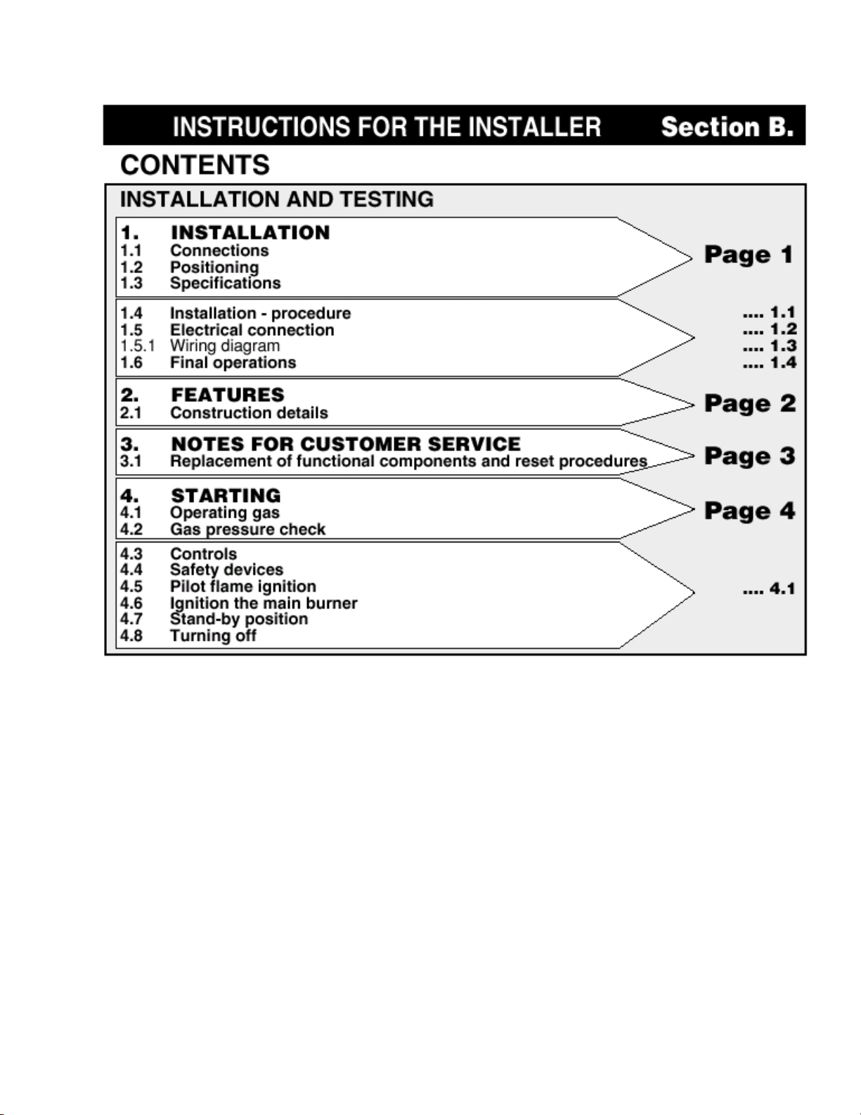
1. INSTALLATION
1.1 Connections
LCG-61D
LCG-61DP
Gas inlet
Flue outlet
Water inlet
Water drain
Terminal board 1 Ph / 3 Ph
Cable gland
Equipotential terminal
Ø
Ø
Ø 1"
3
/4" NPT
*
3
/4"
1
/
2
27.3"
3.9−4.1"
18.1"
5.9-7"
37.4"
35.4"
TB610
The oven must be installed under a ventilation hood only.
*
Not suitable for connection to type B gas vent.
1.2 Positioning
• leave at least 4" clearance
between the rear of the appliance and the
wall
• leave at least 20" clearance at
the sides of the appliance
The cooling outlets of the control
section of the oven (side panel)
must not be near sources of
hot fumes or steam.
WARNING: The oven must be installed on the open stand TB610 only.
3.8"
4.5"
12.4"
2.9"
2"
1.3"
23.3"
37.4"
5.1"
4.3"
13.7"
29.1"
1.9"
All clearance requirements are the same for combustible or non combustible constructions.
For use only on non combustible foor.
1.3 Specifications (total weight of the appliance is marked on the packaging)
ELECTRICAL RATINGGAS
VOLTAGE POWER RATINGINPUT RATING MAX. LOAD (A)
Natural gas 45.000 Btu/h
Propane 45.000 Btu/h
Maximum sound pressure is no higher than 70 dB (A)
120V 1 Ph 60Hz
208V 3 Ph 60Hz
240V 3 Ph 60Hz
- 1 -
0.5 kW
0.9 kW
0.9 kW
4.3 A
3.0 A
3.0 A
1. INSTALLATION
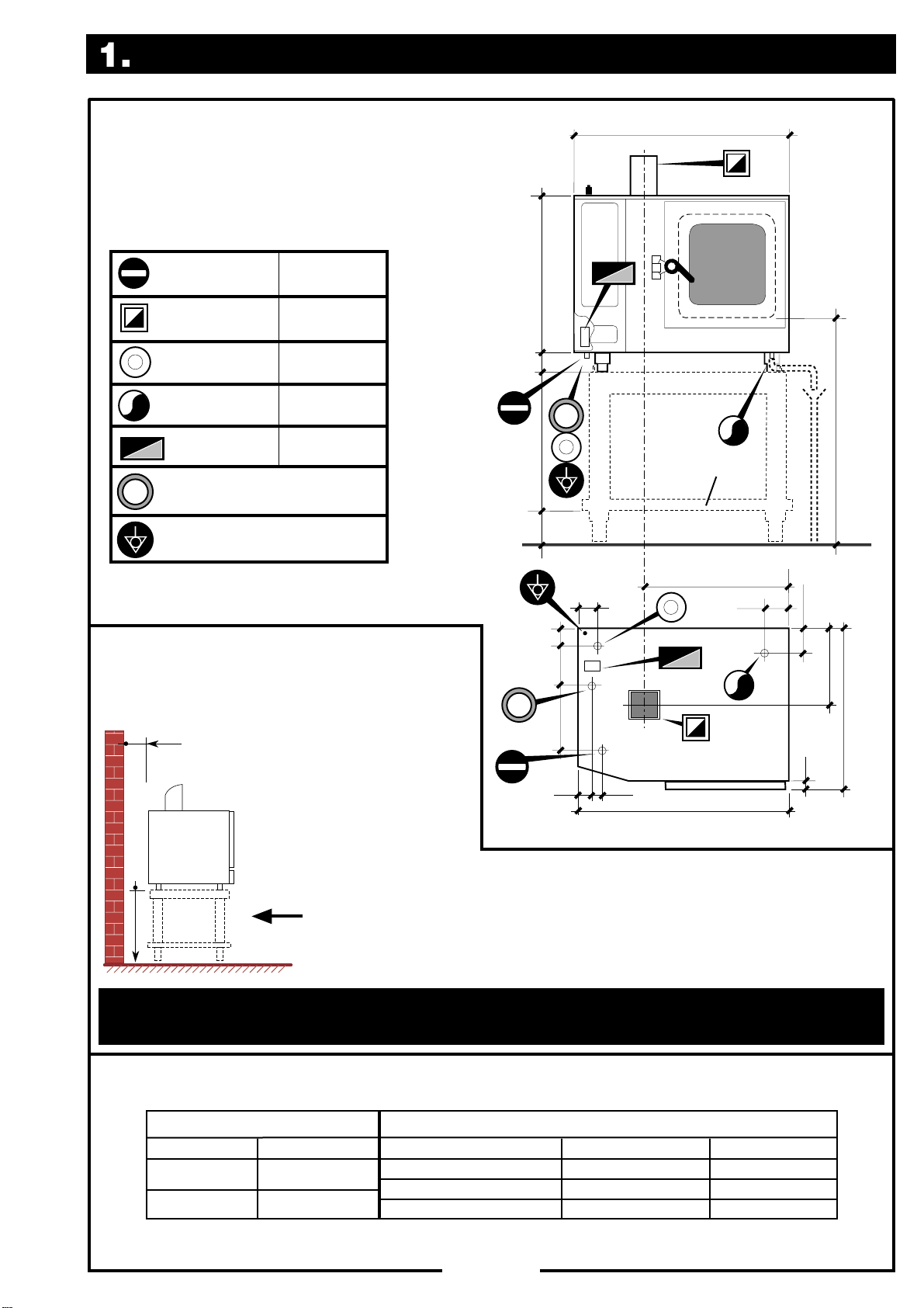
1.4 Installation - procedure
Fit the following units on the
top of the oven:
1) Flue outlet
2) Steam vent
Water connection
3) Remove the lh side
panel by unscrewing the
two fixing screws at the
bottom (if the optional
spray gun is fitted - also
the relative support
screw must be
removed).
1
2
3
Spray gun
support screw
4) Install the filter supplied with the unit in an accessible position on the water inlet, as shown in the
4
examples below:
a) installation on TB610 frame (optional) or other
support not protruding beyond the perimeter
marked by the feet;
b) installation on other support of larger dimensions.
The appliance must be supplied exclusively with cold
water conforming to the following specifications:
Pressure:
(30 - 80 PSI)
between 200 and 600 kPa
;
pH: from 7 to 7.5;
Conductivity: less than 200 µS/cm;
t.d.s. < 100 ppm
Hardness:
90 ...125 ppm)
from 6.3 to 8.8 °e (5...7 °d, 9 ...13 °f, or
(5 ÷ 10° clark);
Max. salinity and ion content in mg/l:
- chlorides < 30; sulphates < 40; Fe (iron) < 0.1; Cu
(copper) < 0.05; Mn (manganese) < 0.05.
Pressure
gauge
Water
pressure
regulator
screw
3/4"
The internal pressure gauge must show a
pressure of 100 kPa (15 PSI); if it shows
a different value, adjust to the correct
pressure by means of the pressure regulator
screw.
a
min. Ø 1"
min. 5% (3°)
max. 5 ft
1/2
1-1
min. Ø 1"
b
Water drain
WARNING: to ensure the
appliance operates correctly and
to avoid the risk of serious
damage, the drain must be vented
(i.e. in communication with the
atmosphere). The material of the
1/2
drainage pipe must be heat
resistant type and not flexible.
1. INSTALLATION
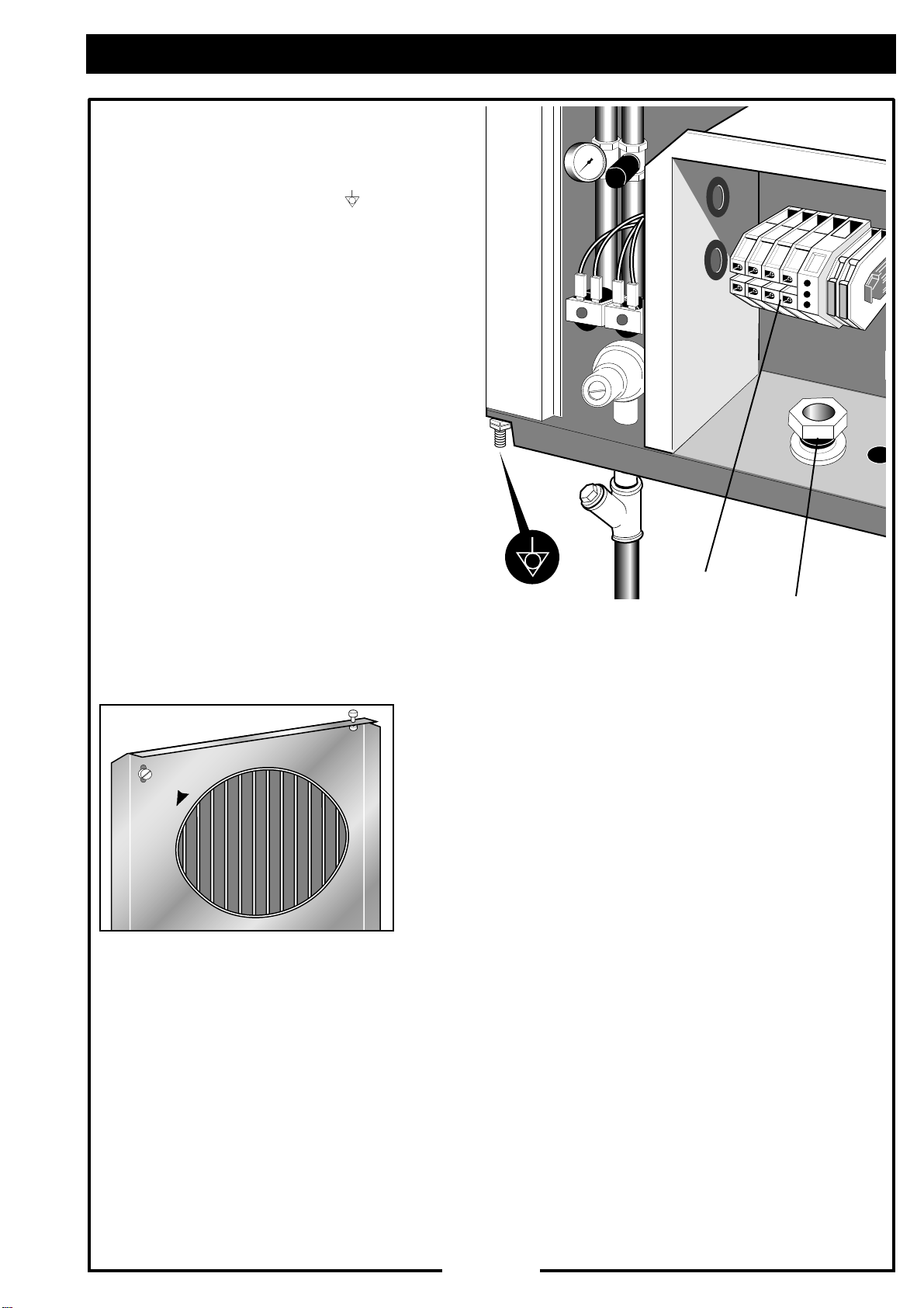
1.5 Electrical connection
Equipotential connection
• The equipotential terminal ( ) is located
beneath the appliance at the rear lh corner.
Mains connection
• Remove the lh side panel as indicated in
heading 1.4.
• Read the general precautionary notes in
Chapter 4, Section A. of this
handbook.
• Fit the suitable cable gland in the relative
hole.
• Route the cable from the main power
switch through the cable gland, and connect the wires to the terminal board (see
electrical diagram on next page).
terminal board
cable gland
N.B.: After making the connection ensure that the motor
turns in the direction indicated by the arrow on the fan
shroud (in the oven chamber).
1-2
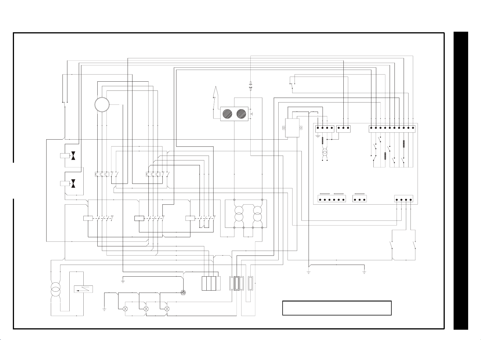
1.5.1 Wiring diagram
48
1-3
SAFETY
THERMOSTAT
WATER DRAIN
WATER INLET
SOLENOID VALVE
20 13
0
-T2
0 120
3a3
-Q3
P3
-Y1
EVS
EVS
SOLENOID VALVE
-Y2
EVC
EVC
CONTACTOR
240
-M1
FAN
MOTOR
14
-Q1 -Q2
39
38 37 36
-K1
24
77
78
A2
A1
ELECTRIC IGNITION
L
N
MOTOR
U1 V1 W1
PE
M
3~
U2 V2 W2
56 57 58 59 60 61
53
62
97
6
969598
12345
12345621
-K2 -K3
22
SLOW
SPEED
12345
44
A2
12345621
A1
28 28
25 26 27
-EY3
-K4
PANEL DX
74
-E2
73 72 71
4
LAMP
PE
LAMP
1
PE
1. INSTALLATION
42
-S1
1
68
76
U1 U2
PE
FC FILTER
L1 L2
16 15
-N2
F3
LN
64 65 45 46 32 52 23 22 21 47 19 18
R3
STB CHAMBER
DOOR SWITCH
R2
F2
R1
F1
R4
R7
R5
1234567891011121314151617
-N1
ELECTRONIC BOARD 240VAC
DRAIN
CHAMBER
PROBE
PROBE
18 19 20 21 22 23 24 25 26
43
75
-E3 -E4
ELECTRIC CABINET PANEL SX
CORE
PROBE
WATER INLET
PRESSURESWITCH
27 28 29 30
41 63 55 54
PC
DRAIN
PRESSURE
C
SWITCH
-K6-K5
42
LCG-61D /DP 208/240V 3Ph
PS
C
SAFETY
THERMOSTAT
-Q3
THERMOCOUPLE
GAS
1
SOLENOID
VALVE
P1
EVG1
EVG2
-K7
IGNITION
PUSHBUTTON
P1
P2
DOOR
MICRO-SWITCH
-Y3
97
6
969598
22
FAST
SPEED
28
7
8
9
40
66
67
ELECTRIC CABINET
65
PE
-H1-H2-H3
LAMP
2
3
-E1
A2
A1
95
49 50 51
12345621
-X1
69 70
024
22
-T1
TRANSFORMER
3131
0 240
F1 1A
F2 1A
34
12
F3 0.5A
87
F6 0.032A
FUSE HOLDER
35
11
L1
L2
L3
PE
POWER SUPPLY
TERMINAL BOARD
1. INSTALLATION
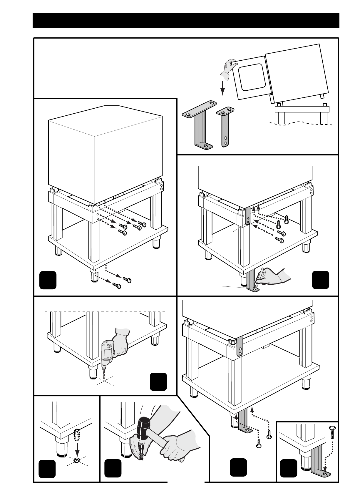
1.6 Oven fixing
CAUTION: do not apply any stress to the door when
it is opened because the oven can tilt frontwards.
To prevent this, use the brackets A and B to secure
the oven to the floor.
1
BACK SIDE
A
A
B
B
2
4
5
3
1-4
6
7

2. FEATURES
2.1 Construction details
8
9
10
11
12
13
14
15
2
1
6
16
3
7
5
4
O
F
F
P
I
L
it
O
T
O
N
LCG-61D
LCG-61DP
1) Flue outlet
2) Steam vent pipe
3) Adjustable foot
4) Drip tray
5) Ignition position
6) Burner start enable position
7) Stop position
8) Stand-by key
9) Alarms display
10) Cooking mode selection keys
11) Special function keys
12) Thermostat controls
13) Timer controls
14) Core temperature probe selector
15) Programming - memory storage section
16) Cooking START/ STOP key
only DP
*
-
-
*

3. NOTES FOR CUSTOMER SERVICE1.6
3.1 Replacement of functional components and reset procedures
The above operations must be carried out by skilled and authorised personnel.
Disassemble only the specified side panels. Do not remove the rear panel.
WARNING
☞
Replacing light bulbs or the diffuser glass
☞
Disconnect the electrical supply
by setting the main power switch
to OFF.
- remove the rh side panel by unscrewing the relative
screws
- unscrew the screw and nut shown in the figure and
withdraw the lampholder support; replace the bulb
with a bulb of identical specifications.
- to remove the diffuser glass for replacement, unscrew
the other three nuts inside the lampholder and
withdraw the glass.
OFF
T
Replacing fuses
☞
Remove the lh side panel;
- the plug-in type fuse holders are located at the side of the
terminal board; replace with rapid-acting fuses (see value on
electrical diagram).
Resetting overload cut-outs
☞
Remove the lh side panel.
- The overload cut-out disconnects the power supply to the motor
in the presence of overheating due to overload; before pressing
the reset button, find and eliminate the cause of the overload.
☞
Resetting the safety thermostat
The safety thermostat shuts down the oven
when internal temperature exceeds 572°F.
To restart the oven:
1
F1
R7
30
R5
6
29
R4
F2
28
R3
- Remove the lh side panel.
- Allow the oven to cool for about 10 minutes,
find and eliminate the cause of overheating
and then press the reset button.
27
26
R2
R1
12
109 87 65 43 2
25
2223
111213
2324
22
N
21
14
L
20
15
F3
16
19
21
17
18
120V
21 - Oven temperature probe
22 - Food temperature probe
23 - Drain temperature probe
24 - Safety contactor
25 - Backup thermostat
9
18
L
U
25
LC
L
U
19
10 - Fan motor
12 - Electronic card
16 - Motor overload cutout
18 - Safety thermostat
19 - LC filter
1
WARNING: VOLTAGE BETWEEN L1 AND N MUST BE 120V
A1
A2
A1
A2
2
8
24
3N
L
2
L
208V3N
240V3N
1
L
1B
F1
F2
5 - Water inlet solenoid valve
6 - Inlet pressure switch
7 - Lighting = 2 x 25 W
8 - Heating element contactor
9 - Door microswitch
10
3
A1
A2
V2
16
W1
V1
U2
U1
W2
77
5
7
4
1 - Terminal board
1B - Fuse carrier (F 0.5 A)
2 - Heating elements
3 - Motor contactor
4 - Drain solenoid valve
ELECTRICAL DIAGRAM
- 3 -

4. STARTING
4.1 Operating gas
Check the data plate
☞
to make sure the
appliance has been
tested for the type of
gas available.
Mod
FCV61DM XXXXXXXXX
G110-8
mbar
5,5
mbar
mbar
mbar
11
5,5
mbar
11
5,5
mbar
11
G120-8
G140-8
kW
kW
kW
2,84
2,53
2,96
G20-20
mbar 20 mbar
m3/h
G25-20
mbar 20 mbar
m3/h
G30-50
mbar 50 mbar
m3/h
Mat
XXXXXXXXXX
11
kW
1,16
m3/h
11
kW
1,16
m3/h
11
kW
0,87
kg/h
400V3N 50 Hz 400 W
Cat
G31-50
mbar 50 mbar
230V1N 50 Hz 400 W
11
kW
0,85
kg/h
400V3N 50 Hz 400 W
4.2 Gas pressure check
Close the main gas valve!
☞
- open the door placed;
☞
- remove cap screw of the pressure test point and connect a
pressure gauge to this outlet;
- open the main gas valve and turn on the appliance at
maximum capacity (see "Starting");
- make sure the pressure lies within the limits indicated in the
table below.
GAS
OFF
50
48
46
44
40
38
36
After this check, remove the pressure gauge and close the pressure test point!
☞
Gas type
natural gas
propane
Pressure in Inches Water Column
rated minim. maxim.
7" 4" 10"
11" 8" 13"
- 4 -

4. STARTING
4.3 Controls
BURNER IGNITION CONSENT
MARK OF REFERENCE
4.4 Safety devices
IN LOWER COMPARTMENT
A thermocouple device locks the gas outlet in case the flame is
extinguished. A further safety thermostat is released in case the oven is
overheated.
4.5 Pilot flame ignition
Press the control knob and turn it to the PILOT position. Press the knob
and light the pilot flame keeping the knob fully pressed for a few seconds.
Release the knob and check that the pilot flame stays on. If it goes out
repeat the lighting operations.
4.6 Ignition the main burner
Press the control knob and turn it to the ON position. The gas way to the
main burner is opened by powering the automatic shut-off valve.
4.7 Stand-by position
STOP
GAS
it
N
O
O
F
F
P
T
I
L
O
O
F
F
P
I
L
it
O
T
O
N
To maintain the main burner off with the pilot burner on, press and turn
the control knob to the PILOT position.
4.8 Turning off
Press and turn the control knob to the OFF position.
GAS
WARNING: WHEN YOU HAVE FINISHED USING THE OVEN,
CLOSE THE MAIN GAS SUPPLY VALVE AND SWITCH OFF THE
MAIN POWER SWITCH FOR AT LEAST FIVE MINUTES BEFORE
RELIGHTING.
- 4-1 -
OFF

INSTRUCTIONS FOR THE USER
LCG-61D & LCG-61DP
09 II1999
39D0880

Section A.
GENERAL INSTRUCTIONS
1. Contents
2. Hazards in the work environment
2.1 Fire
2.2 Accidents
2.3 Electricity
2.4 Gas
3. Correct use
3.1 Working in safety
3.2 What to do in the event of a malfunction
3.3 Prolonged period of non-use
3.4 Definitive deactivation of the equipment
4. Malfunctions
4.1 Problems, causes and remedies
1
2
3
4
5. Maintenance
5.1 Maintenance contract
5.1.1 User-serviceable parts
5.2 Advice
6. Cleaning
6.1 Cleaning of appliances
6.2 Cleaning of stainless steel
6.2.1 Ordinary daily maintenance
6.2.2 Precautions during use
6.2.3 Protecting the stainless steel
7. Observance of regulations
7.1 Standards and regulations
7.2 Liability
5
6
7
8
- 1 -

2. HAZARDS IN THE WORK ENVIRONMENT
2.1 FIRE
Curtains, cloths, chopping-boards or other wooden objects must be kept a safe
distance from hobs and other heat sources; the same applies to vessels
containing alcohol, solvents or inflammable cleaning agents, etc. The risk of
fire in a kitchen is very high.
Fires usually start in a precise point and can be prevented from spreading if
panic is avoided. Hasty reactions may worsen the situation. Never use water to
extinguish an electrical fire; first disconnect the electrical power supply then
extinguish the fire using suitable materials or fire extinguishers.
2.2 ACCIDENTS
There is also a high risk of personal injury (burns, falls) in a commercial kitchen.
Make sure the handles of pans do not protrude from the hob, and frying pans
and other fryer equipment must not be left unattended at any time. Any oil or
grease spilled on the floor must be cleaned up immediately to prevent
slipping.
2.3 ELECTRICITY
The most serious hazards associated with electricity are those of fire
and electrocution.
Follow the safety instructions below:
• Electrical installations: all installation and maintenance should be
carried out by a qualified electrician in accordance with current safety
standards. The main switch must be easily accessible. Cables, plugs
and sockets must be kept in perfect condition.
• Safety: always turn off the main switch before cleaning or any other
operation on the appliance.
Never pull on a power supply cable to unplug an appliance from a
socket.
Do not attempt to repair a damaged cable with insulating tape or other
means, have the entire cable replaced by qualified personnel.
2.4 GAS
The smell of gas is a sign of a probable leak. In this event, close the main shut-off
valve, open doors and windows, and take care not to cause any sparks or
flames.
If you cannot identify the cause of the leak, call a qualified service engineer.
A high percentage of accidents happen because the gas appliances are not
checked regularly: gas appliances are only safe if they are kept in perfect
working order (see chapter 5).
Essential safety precautions when working with gas appliances
To light a gas burner, first bring the flame near to the burner and then turn on the gas.
It is important that the gas burns properly (blue flame) and that there are no restrictions in
the flueways, as these might give rise to dangerous emissions of carbon monoxide
fumes (which are even more hazardous than mains gas, because they are odourless
and give poisoning symptoms that may be confused with harmless disorders).
We strongly recommend the installation of electronic sensors by qualified personnel.
- 2 -
3. CORRECT USE
Adhere scrupulously to the instructions in Section B and do not tamper with the appliance's
☞
safety devices, as this would invalidate any warranty and release the manufacturer from all
liability.
The equipment may be utilised only for the specific uses for which it is intended (as indicated
☞
in Section B).
Any other use is deemed improper and thus hazardous.
THE MANUFACTURER ACCEPTS NO LIABILITY FOR ANY DAMAGE, LOSS OR INJURY
DERIVING FROM INCORRECT INSTALLATION OR USE AND IN THIS CASE DOES NOT
GUARANTEE THE CORRECT OPERATING OF THE APPLIANCE.
3.1 WORKING IN SAFETY
Not to know or to underestimate the risks deriving from the incorrect or improper use of the
appliance can be very dangerous. It is important to adopt working habits in the daily use of the
appliances:
☞
learn the correct use of the various appliances which comprise the
installation;
☞
☞
☞
Inexperience, negligence or haste may cause situations of emergency which otherwise could
have been avoided. Prevention is the first rule for working in safety. Ensure that the electrical
system is perfect order and that gas appliances are inspected regularly. Always think beforehand
of what you are about to do and how to do it, and act in such a way as to ensure your own safety
and that of your colleagues.
after each use, always make sure that all appliances are turned off and
then close the shut-off valve and/or turn off the main switch;
do not use inflammable cleaning agents and do not leave containers with these
substances near the appliance;
the appliance is intended for professional use and must be used by qualified
personnel only!
check the correct operation of the appliance every 6 months. On type B appliances, the
☞
fume exhaust duct must also be checked.
3.2 WHAT TO DO IN THE EVENT OF A MALFUNCTION
Do not attempt any repairs yourself. Turn off the main switch, gas shut-off valves,
water taps, etc. as applicable, and call a qualified service engineer.
We strongly recommend that you contact our Service Centre in your area, which
can provide the necessary expertise and equipment, and which maintains a stock
of original replacement parts.
3.3 PROLONGED PERIODS OF NON-USE
If the appliance is not to be used for a prolonged period, close the gas shut-off valve and/or turn
off the main switch. Clean the appliance thoroughly as indicated in Section B, and protect it
from dust with a cover allowing free air circulation.
3.4 DEFINITIVE DEACTIVATION OF THE EQUIPMENT
Seek assistance from qualified personnel.
- 3 -

;
;
4. MALFUNCTIONS
4.1 Problems, causes and remedies
The guide below will help the User to rectify minor faults; in the event of any other problems,
contact the approved Service Centre, the only service centre authorised to repair the
appliance.
• SMELL OF GAS
This may be an occasional leak: Boiling water has extinguished a flame, but in this case the safety device
intervenes and locks the gas outlet before a dangerous gas concentration is reached in the room. Close the
gas cock and aerate the room. If this is not the cause, have the equipment checked by skilled personnel.
• THE PILOT FLAME DOES NOT IGNITE
Check that the ignition device (whether electric, piezoelectric or electronic)
functions correctly; try igniting the pilot flame with a match.
There may be air in the piping, especially after a period of non-use; in this case, repeat the ignition
operation, this time trying for a little longer.
• THE PILOT FLAME DOES NOT REMAIN LIT
The control knob is being released too soon, before the thermocouple has had time to reach operating
temperature. Repeat the ignition operation, but keep the knob pressed in for a little longer.
• THE PILOT FLAME IGNITES BUT THE BURNER REMAINS OFF
Check that thermostat control knob is turned to a temperature setting and activate the
ignition enabling device (if present).
If the gas flow is controlled by an electric or electronic system, make sure the system is
receiving electrical power (any displays or indicator lights must be lit).
• DEFECTIVE COMBUSTION (YELLOW FLAME)
This may be caused by dirt in the burner or by clogged smoke pipes. It may also be caused by
dripping condensate created by an obstruction or dirt in the flue.
Call a competent service engineer.
• MALFUNCTION OF ELECTRIC EQUIPMENT
This may be due to the absence of a supply phase (frequent tripping of the overload
cutout): check any fuses and replace if necessary.
If either the thermal-magnetic circuit breaker or residual current device (RCD) trips continuously, call an
authorised service engineer.
• PROBLEMS WITH WASHING EQUIPMENT
Poor washing results (dishwashing machine, vegetable washer, etc.) may be due
to the lack of a supply phase (see above) or to too little water pressure, in which
case a pressure boosting device must be installed. It may also be necessary to
install a water softener if white deosits are left on dishes after washing.
• INSUFFICIENT COOLING IN REFRIGERATING EQUIPMENT
This may be due to incorrect positioning (near to heat sources), or to excessive ice on
the evaporator (appliances without automatic defroster), in which case it will be
necessary to defrost manually
.
• INSUFFICIENT AIR SUCTION IN EXHAUSTING SYSTEMS
Ensure all grease filters are kept clean.
- 4 -
;;;;
;;;;
5. MAINTENANCE
5.1 MAINTENANCE CONTRACT
It is advisable to have the equipment regularly checked by a qualified service
engineer so as to ensure its efficiency and to guarantee maximum working safety.
We therefore recommend that the user enters into a maintenance contract with
specialised companies capable of guaranteeing the following operations:
☞
☞
☞
☞
5.1.1 User-serviceable parts
The user is only authorised to replace any deteriorated service components
(handles, removable basins, grilles, etc.). The user is not authorised to
replace functional components or to tamper with the appliance in any
way.
The parts that may be replaced by the user are explicitly listed in section 2 of
manual B together with instructions for their replacement. If this information is
missing, consult a qualified service engineer.
N.B.: intentional damage, or damage due to lack of care or
negligence or to failure to observe the prescriptions,
instructions and standards, or due to incorrect connections
or non-authorised tampering with the appliance, negate any
guarantee or liability on the part of the manufacturer.
Maintenance of service installations
Regular inspection of appliances
Conversion operations (change of gas type or operating voltage)
Repairs.
5.2 ADVICE
Make a note of the emergency phone-number
of your qualified service engineer.
- 5 -

6. CLEANING
6.1 CLEANING OF APPLIANCES
•
Before cleaning, close the main gas valve and/or the main electrical power
switch and allow the appliance to cool.
• To clean any stainless steel, chromium-plated, enamelled, plastic,
duraluminium or painted parts, use lukewarm water and non-abrasive, noncorrosive commercial detergents. Rinse and dry thoroughly after cleaning.
OFF
• Never use water jets
pressure water jets. See also the detailed cleaning instructions indicated in
Section B.
• For the proper care of stainless steel parts, adhere scrupulously to the
recommendations below.
directly on the appliances for cleaning, particularly high-
6.2 CLEANING OF STAINLESS STEEL
Stainless steel is so called because it is not affected by oxidation; this is due to a thin molecular
layer of oxide on the surface which protects against further oxidation.
There are, however, substances which can modify or destroy this layer, giving rise to corrosion;
besides preventing the protective film of oxide from reforming, these substances corrode the
stainless steel itself and can cause irreparable damage.
It is therefore necessary to prevent this by choosing correct cleaning products and by complying
with the following simple recommendations: never forget that when using these appliances, the
first and fundamental rule is to guarantee that the treated products are both non-toxic and
hygienic.
Before using any detergent to clean either the stainless steeI or the immediate and surrounding
floor area, always ask your supplier for the most suitable product which does not cause corrosion
on the steel itself; the onset of rust is most commonly caused by the use of unsuitable cleaning
materials (strongly acid chlorate based detergents) or on inadequate maintenance.
6.2.1 Ordinary daily maintenance
Carefully and frequently cIean the surfaces using a damp cloth; use soap and water
or normal detergents, so Iong as these do not contain abrasives or chlorine
based substances such as sodium hypochlorite (bleach), hydrochloric acid or other
such solutions. These products quickly and irrepairably corrode stainless steel.
When cleaning fIoors underneath or near the appliances, never use the above
mentioned products as vapours or splashes could subject the steel to similar
destructive effects.
Only ever rub in the direction of the satining, then thoroughly rinse with clean water
and carefully dry.
☞
Spots of baked food: wash spots of baked food with hot water before they
have time to harden. If the residue has already hardened, use soap and
water or detergent without chlorate, using a wooden spatula or fine
stainless steel wool if necessary; thoroughly rinse and dry.
- 6 -

☞
Scale deposits: scale deposits at the bottom of tanks, pans, etc., must be removed with
commercial descaling products applied according to the relative instructions.
☞
☞
☞
Scoring: scratches on the surfaces must be smoothed with very fine stainless steel wool,
or synthetic fibrous abrasive pads, by rubbing in the direction of the satining; rinse well and
dry. Never use wire wool on stainless steel surfaces since very small iron deposits could
remain there and create the formation ot rust by contamination.
Rust: water supply pipe, inevitably convey particles of rust dissolved in the water especially
in new installation plants or when taps are opened after a period of inactivity. These iron
deposits must not be allowed to remain on the stainless steel since
they produce rust by contamination.
Use suitable products to remove any rust marks, from companies
which produce detergents for industrial use.
After application, thoroughly rinse with clean water, neutralizing the
action of the product with an alkaline detergent normally used to clean
such appliances or with another specific product.
Burns: to eliminate burns or scorch marks from the steel, use soft
stainless steel wool or abrasive latex soap, carefully rub in the
direction of the grain of satin finish and take care to prevent the
surface from becoming scratched; thoroughly rinse and dry.
6.2.2 Precautions during use
☞
6.2.3 Protecting the stainless steel
When not in daily use, stainless steel is best treated with a thin film of oil, vaseline or
similar oil based product.
Sauces and condiments: all stainless steel vessels used to hold acid ingredients (vinegar,
salt, lemon juice, tomato, etc.) must be thoroughly cleaned.
Use only fine grain salt as an additive to cooking procedures.
Do not allow any salt deposits to remain in pans or containers after use.
Store containers uncovered.
- 7 -

7. OBSERVANCE OF REGULATIONS
7.1 Standards and regulations
All laws, standards and regulations in force on the installation site must be observed,
including:
☞
☞
☞
☞
☞
☞
☞
☞
☞
7.2 Liability
Safety at work and accident prevention regulations;
Signs indicating obligation or prohibition;
Fire prevention standards;
Ventilation and the reduced emission of atmospheric pollutants;
Safety and maintenance of systems and flues;
Drains and waste treatments;
Production areas and the separation of work areas in compliance with hygiene
regulations;
Correct disposal of waste;
Environment hygiene, personal hygiene, food product hygiene.
The owner or manager of the kitchen is responsible for the following:
• the ensure conformance to the above regulations during the installation stage
and the observance of these regulations by the workforce;
• the training and conduct of kitchen personnel.
- 8 -

Section B. -
INSTRUCTIONS FOR THE USER
LEARN TO USE THE APPLIANCE
1. SUMMARY
2. FEATURES
2.1 Construction details
3. OPERATING INSTRUCTIONS
3.1 Quick reference guide
3.2 Using the oven
3.2.1 Cooking without programming
3.3 Alarm signal
3.3.1 Fault finding
3.4 Advanced functions
3.4.1 Cooking with programming
Page 1
Page 2
Page 3
.... 3.1
.... 3.2
.... 3.3
3.4.2 Starting a cooking programme
3.4.3 Remarks on special featurees
4. CORRECT USE AND CLEANING
4.1 Correct use
4.1.1 What to do in the event of a malfunction
4.1.2 Grid-container rack support frames
4.1.3 Optional accessories
4.2 Cleaning
4.2.1 Routine daily cleaning
4.2.2 Periodical cleaning of operating parts
4.2.3 Cleaning prior to prolonged periode of disuse
5. MAINTENANCE
5.1 Maintenance contract
6. ACCESSOIRES
.... 3.4
Page 4
.... 4.1
.... 4.2
Page 5
- 39D0230 -

2. FEATURES
2.1 Construction details
8
9
10
11
12
13
14
15
2
1
6
16
3
7
5
4
O
F
F
P
I
L
it
O
T
O
N
LCG-61D
LCG-61DP
1) Flue outlet
2) Steam vent pipe
3) Adjustable foot
4) Drip tray
5) Ignition position
6) Burner start enable position
7) Stop position
8) Stand-by key
9) Alarms display
10) Cooking mode selection keys
11) Special function keys
12) Thermostat controls
13) Timer controls
14) Core temperature probe selector
15) Programming - memory storage section
16) Cooking START/ STOP key
only DP
*
-
-
*

3. OPERATING INSTRUCTIONS
3.1 Quick reference guide
ON-OFF BUTTON
STAND-BY key with green light idicator
(it switches on only when the appliance is
connected); by pushing the key the electronic panel and the light inside the cooking
chamber activate and deactivate..
ALARMS
See paragraph 3.3.1 to
identify the failure code
(from E1 to E7) shown on
this display
Flashing red indicator:: it lights when the
temperature inside the chamber is too high
for the selected cooking programme
Flashing red indicator: it lights either
when there is not enough water for the
cooking and when the pressure is
inadequate; it also lights together with
alarms E6 and E7 (and in this last case the
alarm display does not light)
Red indicator: it lights when the appliance
has been working for five hours and cleaning operation is due as per section 4.2.1.
By pushing the START-STOP key the five
hours count is reset and resumes from
zero.
Note.: for more details on these indicators, see section
3.3and 3.3.1.
COOKING SELECTION BUTTONS
STEAM COOKING with green indicator
(ON when the program has been chosen).
Working temperature range: from 122 to 218°F.
CONTROL BUTTONS
WATER INLET button (it can be activated
only with MIXED COOKING and
REGENERATION); the relevant display shows
the humidity percentage level
FULL or HALF SPEED FAN selection button
(it can be activated only with CONVECTION
COOKING - MIXED COOKING REGENERATION); the green indicator is on
when the low ventilation is activated
CONSERVATION at 158°F key with green
light indicator on when it is activated; sets a
chamber temperature of 158°F with low
ventilation; it switches on automatically at the end
of a cycle and is deactivated by key STOP
CHAMBER TEMPERATURE button: when
the cycle is not on it temporarily switches the
display reading from the set temperature to
the sensed one; when the cycle is on it
switches the display readind from the sensed
temperature to the set onea
COOKING TIME button: when the cycle is on
it switches the displayed value from the left
time to the set time; when the cycle is not on
the display is always showing the set time.
In case of cookings in sequence: when the
cycle is not on it switches the display from the
the set time of that cycle to the total time of
the sequence; when the cycle is on it switches
from the count-down of that cycle to the total
count-down of the sequence
CORE TEMPERATURE button: when the
cycle is on it switches the display from the set
temperature to the temperature sensed by the
probe; when the cycle is not on it activates or
disactivates the core temperature cooking
CONVECTION COOKING with green
indicator (
chosen).
Working temperature range: from 122 to 482°F.
MIXED COOKING (CONVECTION +
STEAM) with green indicator (ON when
the program has been chosen).
Working temperature range: from 122 to 482°C
REGENERATION with green indicator
(ON when the program has been chosen).
Working temperature range: from 284 to
338°F.
OVERHEATED STEAM COOKING with
green indicator (on when the program
has been chosen).
Working temperature range: from 230 to
257°F.
UP-DOWN BUTTONS
ON when the program has been
they allow to increase and
decrease the numeric value
shown on the relevant display
PROGRAMING BUTTONS
PROGRAMME MEMORY selection button: it
activates the programme setting and the
relevant display shows the last selected
programme (P01-P99)
Selection button for "COOKINGS IN
SEQUENCE": steps from a cooking
programme to the next in the series (to see or
to set); by pushing it during the cooking phase
it is possible to modify the displayed cooking
MEMORY ERASE button: it allows to cancel
programmes or cookings in sequence (the
displays relevant to the memories are
flashing); pushing it twice (without pushing key
ENTER) the erasure operation is cancelled.
ENTER button: it allows to store the modified
data or to erase either a program or a cooking
programme from a series
START-STOP BUTTON
Button to START-STOP a PROGRAMME
with green flashing indicator during the
cooking phase
- 3 -

3. OPERATING INSTRUCTIONS
3.2 Using the oven
N.B.: At the start of each cooking session we advise preheating the oven by
running a short cooking cycle when empty; at the end of the cycle the oven will
automatically stop and an audible signal will sound for 30 seconds.
Coooking
Cooking can be carried out without programming, in which case cooking mode, time and
temperature (see below) must be set manually, or using pre-stored cooking programs (refer
to cooking with programming in subheading 3.4.1).
3.2.1 COOKING WITHOUT PROGRAMMING
- If displays 24 and 27 are illuminated, press key 25 to deactivate the programming function.
- Select the required cooking mode by pressing one of the
following keys:
6
(STEAM); 7 (CONVECTION); 8 (MIXED mode); 9 (RE-
GENERATION); 10 (SUPASTEAM)
.
- set the required chamber temperature on display 15 by
means of arrow-keys 17;
2
1
3 5
4
Note: when cooking in modes 8 or 9 (COMBI or
REGENERATION), display 11 switches on automatically. By
means of button 12, it is possible to set the humidity inside the
chamber. In modes 7, 8 or 9 it is possible to select "half speed
fan" for cooking delicate products by pressing 13.
Cooking with timer
- select the cooking with timer by means of button 19;
use the arrow-keys 20 to set the cooking time on display 18.
-
- Start the cycle using button 31 (START/STOP); the timer
display will show the count-down to the end of the cycle.
- When the cooking is finished, the heating stops and an
acoustic alarm will activate for some seconds.
Cooking with core temperature probe
- Use button 22 to select probe cooking;
- set the temperature required at the center of the product
6
15
18
21
24
27
7 8 9 10
11
12
16
19
22
25 26
28
31
13
29 30
14
17
20
23
on display 21 by menas of arrow-keys 23.
- Start the cycle using button 31 (START/STOP).
- When the cooking is finished, the heating stops and an acoustic alarm will activate for some
seconds.
Note: when the probe is inserted into the center of the food and activated, the cycle stops when center
of the product reaches the required temperature.
Changing settings during cooking
- The value set can be modified during the cooking phase by keeping the cooking key pressed
while modifying by means of keys 17, 20 or 23.
- To modify the values of a cooking program different from the one being carried out, keep
pressed the key relevant to the wanted cooking and proceed to the modification by means of
keys 12, 13, 17, 20 or 23.
Note: time changes during cooking will affect only the time remaining to the end of the cycle.
3-1
3. OPERATING INSTRUCTIONS
3.3 Alarm signals
During general use of the appliance be aware of the following alarm signals:
When this indicator lamp flashes the oven chamber temperature is too high for the selected cooking
mode. This lamp will light whenever you change from a high temperature cooking mode
(CONVECTION or MIXED) to a lower temperature mode 214-218°F STEAM COOKING,
284-338°F REGENERATION CYCLE, 230-257°F for SUPASTEAM). When
this lamp is illuminated heating is inhibited until the temperature falls to within the permissible range,
after which the lamp will switch off and the oven will operate in the selected mode.
This indicator lamp should not illuminate during CONVECTION or MIXED CYCLE cooking modes.
This lamp flashes to indicate water supply problems (either due to a temporary interruption of the
supply or a drop in mains pressure). If this occurs during a STEAM, REGENERATION or
SUPASTEAM cycle, oven heating is immediately inhibited. At this point press START to check
whether the problem is still present. If the lamp continues to flash (and the water supply is OK)
seek the cause among those listed in heading 3.2. If the lamp starts flashing during
CONVECTION or MIXED CYCLE cooking, the oven will continue to operate normally and the
indicator lamp will switch off as soon as normal conditions are restored.
Illuminates after 5 hours of cooking to signal that the cleaning operations described in
subheading 4.2.1 must be carried out; the oven continues to operate when this indicator lamp is
lit; pressing the START-STOP key switches off the indicator lamp and the operating hours count
restarts from zero.
In the presence of malfunctions this display illuminates and shows an alarm code.
Identify the cause of the problem and remedy it by following the instructions in the
chart below (subheading 3.3.1).
3.3.1 Fault finding
If the oven is not operating, check that the main power switch is set to ON and that mains
power is effectively present (check fuses), or check the following chart:
or
flashing
or
flashing
Indicator lamp flashes
kkkkkkkkkkk
Indicator lamp flashes k
E1
Display shows
following codes:
E3
E4
E5
E6
E7
E8
Indicator lamp is lit
E2
Faulty cooking chamber temperature
probe
If core temperature probe is not skewered in
food and the oven chamber is at ambient
temperature: core temperature probe is faulty.
You have switched from CONVECTION or MIXED mode operation to
REGENERATION or STEAM mode
Mains water supply interrupted or low
pressure
vvv
Water flow control valve is incorrectly
set
Faulty oven chamber temperature probe
Faulty core temperature probe
Faulty steam discharge temperature probe
Motor thermal trip
Safety thermostat trip
Faulty oven chamber pressure switch
Faulty drain pressure switch
Faulty oven chamber lower probe
Oven has been in effective use for 5
hours
Call Customer Service
vv
Call Customer Service vv
vvvv
vvv
Wait for the temperature in the oven
chamber to return to within the specified
range for the selected cooking mode
Inform the water company or install a
pressure increase system
Call a qualified technician to calibrate
the valve or call Customer Service
Call Customer Service
Call Customer Service
Call Customer Service
Call Customer Service
Call Customer Service
Call Customer Service
Call Customer Service
Call Customer Service
Clean the oven as described in
subheading 4.2.1.
or
flashing
Faulty steam discharge temperature probe
3-2
Call Customer Service
3. OPERATING INSTRUCTIONS
3.4 Advanced functions
3.4.1 COKING WITH PROGRAMMING
Storing a single cooking cycle in the memory
- Press key 25 to activate the programming function.
- Select a program (from P01 to P99) using the up/down keys 26.
- Select the desired cooking mode by pressing one of the following keys:
6 (STEAM); 7 (CONVECTION); 8 (MIXED mode); 9 (REGENERATION); 10 (SUPASTEAM).
Note: when cooking in modes 8 or 9 (COMBI or REGENERATION), display 11 switches on
automatically. By means of button 12, it is possible to set the humidity inside the chamber. In modes
7, 8 or 9 it is possible to select "half speed fan" for cooking delicate products by pressing 13.
- Set the required chamber temperature on display 15 by
means of arrow-keys 17;
Choose
2
1
3 5
4
Timer control
- select timer control
cooking by means of
button 19;
- use arrow-keys 20 to
set the cooking time
on display 18.
N.B.: after setting of a time value (or core temperature
value), display 27 will show 1-1 (program composed by a
single cooking cycle); first digit = active cooking cycle,
second digit = total number of cycles in the sequence (see
below: storing a sequence).
- Push key 30 to store the cooking cycle. This cycle can
be used as a program involving only one type of
cooking, or it can be included in a program involving
Core temperature probe control
- Use button 22 to select
core temperature probe
controlled cooking;
- by means of arrow-keys 23
set on display 21 the
required core temperature.
6
15
18
21
24
27
11
7 8 9 10
12
16
19
22
25 26
28
13
29 30
14
17
20
23
several different cooking cycles in sequence as
explained in following section.
31
Storing a program composed by a sequence of different cooking cycles
- Push key 28: display 27 will show 2-1 (the first digit indicates the running cooking cycle, the
second digit indicates the total number of cycles included in the sequence; it is possible to
store up to 9 cycles in a sequence).
- Set the new cycle as per the instructions in previous section; after having set a time or a core
temperature, display 27 will indicate 2-2 (i.e second cooking cycle of a sequence composed
by two cycles).
Note: by pushing key 19 display 18 will show the total time of the program (sum of the times of
each cyle included in the sequence).
- Push key 30 to store the program.
Changing settings (when the oven is not cooking)
- Use arrow-buttons 26 to select the program to be modified (P01 to P99)
- Use button 28 to select the cooking cycle to be changed
- Proceed with the changes
- Push button 30 to store the data; if button 30 is not pushed, the modifications will be
temporary, i.e. they will be active only until a new program is selected.
3-3

3. OPERATING INSTRUCTIONS
3.4.2 STARTING A COOKING PROGRAM (either single cycle or sequence)
- Should it not be activated, push button 25 to activate program memory.
- Use arrow-buttons 26 to chose one of the previously
stored program from P01 to P99
- Start the cycle using button 31 (START/STOP); the first
cooking cycle of the sequence will start and the timer
display will show the count-down to the end of that cycle.
When the cycle is over, the display will indicate the next
one and so on until the end of the sequence.
2
6
1
3 5
7 8 9 10
4
Note: by pushing button 19 display 18 will show the total time
to the end of the program (sum of the times of the single
cyles included in the sequence))
- When the cooking is finished, the heating stops and an
acoustic alarm will sound for about ten seconds.
15
18
11
12
16
19
13
14
17
20
Changing settings during cooking
- The preset values of time or temperature can only be
21
22
23
changed by keeping pressed the key of the running
cooking mode while changing the settings using keys 17,
20 or 23 (the running cooking mode is identified by the
relative indicator light).
- To change the next-in-the-list cooking program,select
it by pushing key 28, then keep it pressed and proceed
24
27
25 26
28
31
29 30
with the changes by means of keys 12, 13, 17, 20 or 23.
N
ote: any change of time during cooking works only on the count-down
.
- Push button 30 to store the data; if key 30 is not pushed, the modifications will be temporary,
i.e. they will be active only until a new program is selected.
Note:
• If the door is opened while cooking is in progress, not only will the heating and fan stop, but
the timer will also stop; time count-down will start from this point when the door is closed.
• When unplugged, the appliance keeps stored the programs indefinitely.
3.4.3 REMARKS ON SPECIAL FEATURES
• core temperature probe: it can be set in any type of cooking (MIXED, STEAM,
REGENERATION, SUPASTEAM). It excludes the timer and the cooking is stopped as soon
as the temperature in the core of the food has reached the set value.
• half speed fan: allows cooking with the fan at half speed and is added to a program by
means of key 13 before pressing START; the setting is not stored unless ENTER (key 30)
is pressed.
It cannot be added to STEAM or SUPASTEAM cookings
• cook / hold: key 14 activates, at the end of a cooking cycle, a preset program that sets
the chamber temperature at 70°C and the fan at half speed.
It can be either activated and deactivated directly (i.e. pressing 14 only) at any
moment, even during cooking or when a cooking sequence is being carried out; when
the “hold” program starts, it can be stopped only by pressing STOP.
3-4

4. CORRECT USE AND CLEANING
4.1 Correct use
• This appliance has been designed for cooking food products and must be used exclusively
by professionally qualified personnel, as specified in this manual; any other use is to be
considered improper and hazardous.
• Never use spare parts other than as specified and recommended by the
manufacturer.
• Always open the door with care to avoid burning from contact with
steam or hot surfaces
4.1.1 What to do in the event of a malfunction
In the event of a fault not specified in point 3.3, switch off the appliance and call
the nearest authorised Service Centre.
4.1.2 Grid-container rack support frames
The oven chamber is equipped with two support frames with runners designed to hold
Gastronorm trays or containers (depth 1.5"). The support frames are attached to the oven
side panels. To disassemble the frames, lift and remove as shown in the following figure.
L.H. FRAME R.H. FRAME
4.1.3 Optional accessories
A roll-in rack is available on request and equipped with
6 runners to hold GASTRONORM grids or containers
(depth 1.5" or 2.5";
see chapter 6,
section B in this
manual).
- 4 -
3
4. CORRECT USE AND CLEANING
. / . Optional accessories
N.B.: if the roll-in rack is used, a safety
bolt secures it to the guides.
To maintain in the released position, lift
the bolt (detail 1) and rotate toward the
inside so that the stop pin rests on the
ledge (detail 2).
1
.
Grids (or containerss) must be inserted to the
end of the runners so that they do not slip out
during movement of the roll-in rack.
To remove, lift the front section above the
raised edge of the runners and withdraw.
2
4.1.4 Food removal and handling
To move the entire roll-in rack structure with food, a
special transfer truck is used (see accessories,
chapter 6) with the loading surface at the same
height as the oven. In this case the roll-in rack can
be secured to the truck during transport by means
of the bolt described above. The truck is also
supplied with a detachable handle with a heat
insulating grip to attach to the roll-in rack and
facilitate removal.
Strictly observe the instructions supplied for
use of the transfer truck.
CAUTION: the transfer truck
must be handled with the
utmost of care to avoid collision with other persons or
objects and avoid dropping
objects or spilling liquid. Take all precautions and take into account the weight of
the load and risk of burning from contact
with hot parts, food or liquids.
Max. capacity (food + trays): see chapter 6
(ACCESSORIES).
- 4-1 -

4. CORRECT USE AND CLEANING
4.2 Cleaning
• Before cleaning, close the main gas valve and the main electrical
power switch and allow the appliance to cool.
• As regards routine daily cleaning of the frame and stainless steel
parts, refer to chapter 6, section A.
To facilitate cleaning, a detergent spray and spray gun are available
on request (see accessories, chapter 6, section B in this manual).
4.2.1 Routine daily cleaning
Condensate collection tray
• The condensate collection tray must be emptied and
cleaned regularly; if connected to a drain line, make
sure that the outlet is not obstructed.
A.
Oven chamber
• Remove the grid-container rack frames (refer
to point 4.1.2); if the roll-in rack is used,
remove together with its guides;
• Remove and clean the filter-grid at the base of
the oven chamber;
• Spray detergent on the sides of the oven by
means of the special accessory (
• Rinse thoroughly (
CAUTION: never direct cold water jets at
the glass lamp cover when oven
temperatures exceed 150°C
• heat the oven under no-load for 15 minutes at
482°F with the humidifier set to maxi-
mum, followed by 15 minutes without the
humidifier.
) and dry;
*
);
*
(318°F).
• on completion of the above, and when the oven is to be left unused overnight, leave the
door slightly ajar.
(
) Accessories LDL and PND are available for these operations, as specified in
*
chapter 6.
4-2

4 mm
M14
4. CORRECT USE AND CLEANING
4.2.2 Periodical cleaning of operating parts
Fan descaling
Scale should be removed from the fan
frequently, depending on the type of water
used.
• Remove the grid-container rack frames
(refer to point 4.1.2); if the roll-in rack is
used, remove together with its guides;
• Loosen the two fixing screws on the
deflector and rotate on its hinges to
open.
• Remove scale from the fan using a
suitable descaler according to the
manufacturer’s instructions.
N.B. To clean the fan thoroughly,
disassemble as follows:
– Hold the fan in position and unscrew the spherical
diffuser;
– By means of Allen key unloose the two grub
screws on the side of the fan hub;
– secure extractor bolt M14 (supplied as standard)
on the hub to remove the fan from the shaft.
Water inlet filter cleaning
• Close the main water valve, unscrew the cap
and remove the filter to clean.
Drain siphon (below oven)
• Unscrew the cap and remove
any residue.
4.2.3 Cleaning prior to prolonged periods of disuse
• Carry out all cleaning operations described in this section.
• Refer to section A, point 3.3 in this manual.
4-3
A.

5. MAINTENANCE
5.1 Maintenance contract
Refer to chapter 5, section A
The appliance should be thoroughly checked at six-monthly
intervals by a qualified technician (heating unit, mechanical
stability, corrosion...) with particular emphasis on all control and
safety devices.
6. ACCESSORIES
PND
of this handbook.
A.
Do not use accessories other than the ones shown here
SRG6
LDL
SRG6 (*)
SRG685 (*)
C610
LDL
PND
TB610
TB610
C610
Roll-in rack (supplied) with 6 runners for 6
(max. height 1.5")
Optional roll-in rack with 4 runners for 4
(max. height 2.5")
ransfer truck with handle for roll-in rack SRG6-SRG685
T
S
pray gun
etergent spray unit
D
Open support frame
1/1-Gastronorm
1/1-Gastronorm
SRG685
TSR610
containers
containers
(
) Maximum load capacity (food + containers): 73 lb
*
- 5 -
 Loading...