

Page 1
1
Page 2

TABLE OF CONTENTS
CHAPTER PAGE
1. TABLE OF CONTENTS .........................................................................2
2. GENERAL INFORMATION....................................................................3
3. WORKING PRINCIPLE..........................................................................8
4. INSTALLATION...................................................................................... 12
5. OPERATION..........................................................................................33
6. MAINTENANCE & CLEANING............................................................... 48
7. TROUBLESHOOTING ........................................................................... 53
8. TECHNICAL DATA ................................................................................60
9. ELECTRIC WIRING DIAGRAMS ........................................................... 74
10. GAS WIRING DIAGRAMS .................................................................... 93
2
Page 3
GENERAL INFORMATION
Description and Use
Steam Cooking
Advantages to using the Steam Mode:
! No waiting time, steam is immediately generated
! Steam Temperature of 218°F
! Saturated Steam
! Steam while cooking reduces cooking times and energy consumption
! Hea t transfer is 10 times more efficient than boiling water
! Vitamins, Proteins, Minerals, Flavors, and Juices are retained in the food
! Different product flavors do not mix while cooking (i.e. fish, meat, and
vegetables)
! Food shrinkage is minimal
The Combi-ovens with mechanical controls have a circuit board that sets the
temperature to 218°F.
The Combi-ovens with digital controls have a circuit board that can adjust the
temperature from 86°F to 218°F.
Hot Air Convection Cooking
The Hot Air Convection Mode uniformly blows hot air in the slightly
overpressurized cavity. This mode will provide the best ro asting, baking and
browning.
! Meat and poultry pores are immediately closed and their natural juices are
retained
! Hot air does not escape because the unit is watertight
! The insulation of the oven cavity maintains the latent heat longer
! Th is mode can grill, broil and prepare everything that was previously prepared
in pans and stockpots
! Due to the design of the oven cavity and the placement of the fan, grease
does not build up inside the double glazed door
3
Page 4
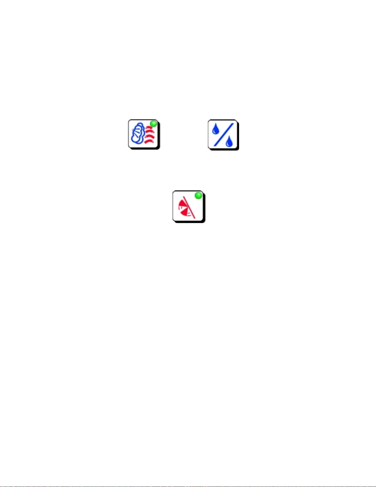
Low Temperature Steaming
Digital Models Mechanical Models
Combi Mode
Steam Percentage
Low Temperature Steaming is controlled by the circuit board on the digital
models. On the Mechanical models low temperature steaming is obtained by
selecting combi mode and setting the steam percentage.
This mode is for cooking delicate or temperature sensitive food, stuffing, eggs,
fish, as well as pre-cooked vacuum-packed products.
Advantages to Low Temperature Steaming:
! The taste of several foods can be enhanced by lowering the temperature
slightly
! Protein products (eggs, stuffing, fish, etc.) do not harden
! Meat and fish products get improved consistency and texture
! Shrinkage and weight loss is reduced
Combining Hot Air with Steam
Digital Models Mechanical Models
Combi Mode
Steam Percentage
Cooking Temperatures from 86°F to 482°F.
The Combi Mode combines hot air and steam together.
Advantages to the Combi Mode:
! Juicer Meat and Poultry, no foil on baked potatoes, stuffed vegetables, etc.
! Full control of the steam percentage in the oven cavity
! Reduced shrinkage and weight loss
! Reduced cooking times
4
Page 5
! Reduced energy consumption
! Reduced cooking temperatures
! Self basting of the food when directly placed on the racks
! Healthier quality of cooked products
Re-heating (Digital Models Only)
Re-heating Mode
Half Speed Fan Control
Steam Percentage
Cooking temperatures from 284°F to 338°F
The Re-heating Mode uses a limited range of temperatures to help when reheating pre-cooked and chilled food.
! The reduced range of temperatures allows you to re-heat little to large
quantities of pre-cooked and chilled food
! You can avoid dried food by using the different percentage levels during the
re-heat process
! Maintains the original color, flavor, and taste as when originally cooked
High Temperature Steam Cooking
Cooking temperatures from 230°F to 257°F
The High Temperature Steam Mode is standard on Digital Models only.
Advantages to the high temperature steam mode:
! No waiting time, steam is immediately generated
! Pressureless high temperature saturated steam
! Steam while cooking reduces cooking times and energy consumption
! Hea t transfer is 20 times more efficient than boiling water
! Vitamins, Proteins, Minerals, Flavors, and Juices are retained in the food
5
Page 6
! Different product flavors do not mix while cooking (i.e. fish, meat, and
vegetables)
! Food shrinkage is minimal
Combi-ovens with mechanical controls and get high temperature steam by
selecting the Combi Mode at temperatures between 230°F and 257°F and the
maximum steam percentage.
+
Cooking with Low Speed Fan Control
The Low Speed Fan Control is standard on the Digital Programmable models
only.
It can be set in the Combi Mode, Hot Air Convection Mode, and the Re-heating
Mode.
The Hold mode automatically uses the low speed fan.
This mode is usually used for pastries, brea d and other deli cate products.
6
Page 7
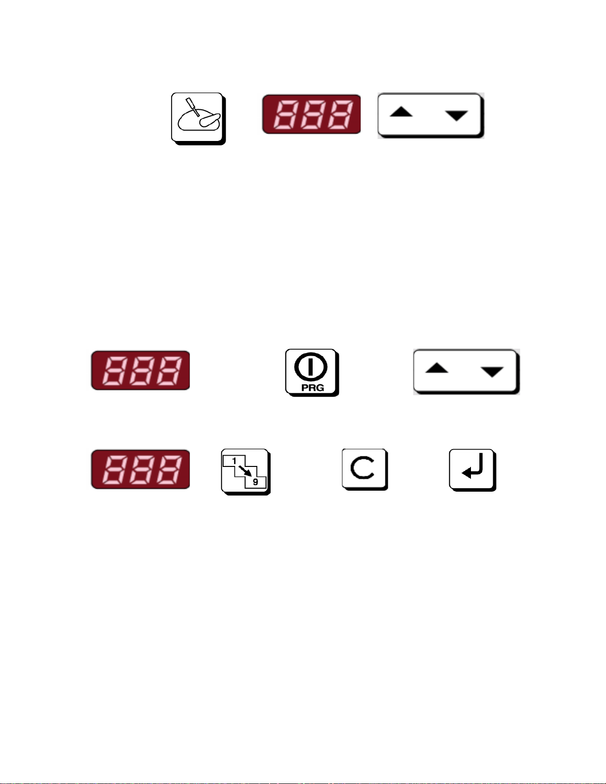
Core Probe Cooking Control
Temperature Control up to 210°F
The Core Probe Control is standard on the digital models only.
Core Probe Control advantages:
! It automatically shuts off the cooking process as soon as the core probe set
temperature has been reached
! Cooking times are not required, products come out exactly the same every
time
! Products can be cooked to rare, medium or well done to perfection
Program Mode
Program Display Program Section On/Off Program Number
Cooking Step Cooking Steps Step / Program Enter / Confirm
Display Cancel (Store)
The Program Mode is standard on the Digital Programmable models only. This
mode allows the user to store up to 99 recipes with up to 9 steps for each
program.
7
Page 8
BOILER SYSTEM LIMITS
! High energy consumption
! Long waiting time to get steam
! Steam generator scale buildup
! High maintenance costs
WORKING PRINCIPLE
8
Page 9
18
21
22
23
19
20
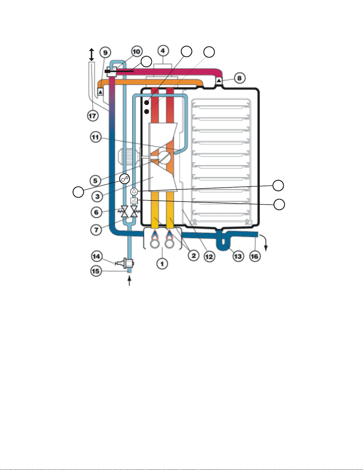
1 Burner 13 Drain Trap
2 Heat Element / Exchanger 14 Pressure reducing valve
3 Fan 15 Water inlet
4 Flue 16 Water Drain
5 Atomizer 17 Steam / Vent Outlet
6 Cooling Water Solenoid Valve 18 Water Pressure Gauge
7 Humidifier Solenoid Valve 19 Water Calibrated Injector
8 Overpressure Valve 20 Pressure Switch
9 Underpressure Valve 21 Drain Temp. Detecting Probe
10 Cooling Nozzle 22 Temp. Controlling Probe
11 Injection Pipe 23 Safety Thermostat Probe
12 Baffle
9
Page 10

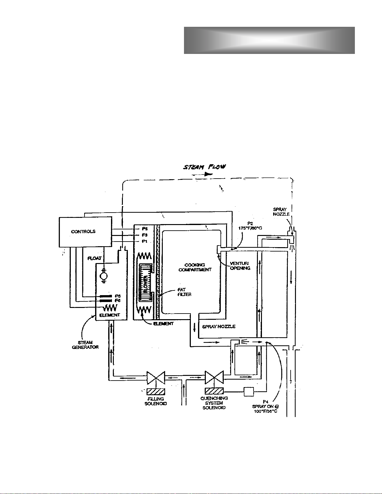
HOW THE LANG COMBI WORKS
In the Lang Combi water is introduced directly into the cooking chamber where it
is atomized on the heat exchanger (2)/heating elements, then immediately
transformed into steam.
In gas models the heating of the cooking chamber is done through the heat
exchanger (2) which is heated by the bottom burners (1).
In the electric models the heating of the cooking chamber is done through the
elements.
The fan (3) is located between the heat exchanger tubes (2) or in the center of
the heating elements. Its function is to increase heat exchange with the air in the
cooking chamber for increased cooking uniformity. The air is drawn from the
center and blown to the sides of the baffle (12) passing through either the heat
exchanger or the elements.
The diffuser (5) is located in the center of the fan (3). Its purpose is to atomize
the water falling on it. Then the fan blows the mist into the heat exchanger or
elements for immediate steam.
The cooking is separated from the heat exchanging area by the baffle (12). The
correct rotation direction of the fan is stamped into the baffle. The baffle is easy
to open for easy cleaning and access.
The cooking chamber and all inner components are made of stainless steel (fan
(3), baffle (12), diffuser (5), etc.).
To obtain the best cooking results, our oven used dry overheated steam. This is
possible by maintaining a slight overpressure in the cooking chamber and a
temperature of more than 212°F.
In steam mode the working temperature of the oven is fixed at 217°F for
mechanical models and is vari abl e from 86°F to 217°F for electronic models,
while the cooking chamber pressure is controlled to 0.05 psi.
The slight overpressure is guaranteed by a sealed door and an overpressure
valve (8) located on the ceiling of the cooking chamber. The overpressure valve
is a simple counterweight to let steam escape when the inside pressure exceeds
0.05 psi.
On all models, the temperature in the steam mode is electronically controlled for
a minimum accuracy of +/- ?°F.
When the internal temperature is hot and a cold product is placed inside or cold
water is injected (11) to create steam, a depression takes place inside the
10
Page 11

cooking chamber. To avoid an implosion, there is another safety valve (9), which
works to restore the internal pressure.
The water system is connected to the atmosphere through the water drain trap
(13) and the upper pipe (17), which is fitted with a silencer. The drain connection
must be ventilated to guarantee a constant pressure inside the cooking chamber.
The drain trap system with the ventilation connection is considered a safety
system to prevent accidental explosion.
Only use cold water for the combi ovens for the following reasons:
! To produce steam through a calibrated injector (11)
! To keep the drain trap clear and permanently full to ensure chamber pressure
! To condensate the steam by means of a wide angle cooling injector (10) so
that most of the escaping steam will be transformed into water and the food
smell particles will be captured and transferre d to the drain system
! T o cool down the liquids in the drain system to reduce the possibility of
bacteria proliferation. The maximum temperature limit is 140°F.
The water inlet pressure has been factory set at 14.5 psi. There is a pressure
regulator (14), which can be adjusted if needed. The quantity of water converted
into steam is determined by the pressure and the size of the injector (19).
When working in steam/super steam modes:
If the pressure is set too high, we can achieve an excessive wet condition where
it will be hard to reach the temperature of 217°F inside the cooking chamber. If
the pressure is set too low, we cannot achieve a saturated steam condition.
The pressure regulator (14) precedes two solenoid valves (6) and (7).
A pressure switch (20) just following the solenoid valve (7) is set at 5.8 psi, when
the inlet water pressure jumps under this value:
! The unit will stop working and the led alarm indicator will light when working in
steam/super steam modes
! An led/display alarm indication (E6 – for electronic models) when working in
combi mode
! An led/display alarm indication (E7 – for electronic programmable models)
when working in convection mode
11
Page 12

INSTALLATION
General Installation Instructions
Positioning
Keep the appliance area free and clear of combustible material and do not
obstruct the flow of combustion or ventilation air.
The installation of any components such as a vent hood, grease extractors,
and/or fire extinguisher systems, must conform to their applicable local/nationally
recognized installation standards.
Gas Connection
All gas connections must be in accordance with local codes and comply with the
National Fuel Gas Code ANSI Z223.1 latest edition, Natural Gas Installation
Code CAN/CGA – B149.1 or Propane Installation Code CAN/CGA – B149.2.
Connect each oven separately. A gas shut off valve must be installed to the
oven(s) and located in an accessible area.
This appliance and its individual s huto ff val v e must be discon nected from the gas
supply piping system during any pressure testing of that system at test pressures
in excess of 1/2 PSGI and the appliance must be isolated from the gas supply
piping system by closing its individual manual shutoff valve during any pressure
testing of the gas supply system at test pressures equal to or less than 1/2 PSIG.
Test Gas
Always check the pressure of the gas supply. Test for gas leaks. Use a
commercial leak detector or a soapy and water solution.
OPEN FLAME TO TEST FOR GAS LEAKS.
Electrical Connection
The appliance must be electrically grounded in accordance with local codes, or in
the absence of local codes, with the National Electrical Code, ANSI/NFPS 70.
Water Connection
This appliance must be installed to comply with the applicable Federal, state, or
local plumbing codes having jurisdiction.
Always install a manual shut-off valve upstream of the appliance.
Downstream of the manual shut-off valve, install appropriate fittings for easy
disconnection of the appliance and filters which can easily be inspected and
cleaned.
Use Materials, seals and fittings approved according to applicable standards.
Use suitable pipes which been have properly treated in order to prevent the
release of iron oxides into the water (as these can alter the taste of the food and
mark stainless steel).
If necessary, install a suitable water treatment system.
DO NOT USE AN
12
Page 13
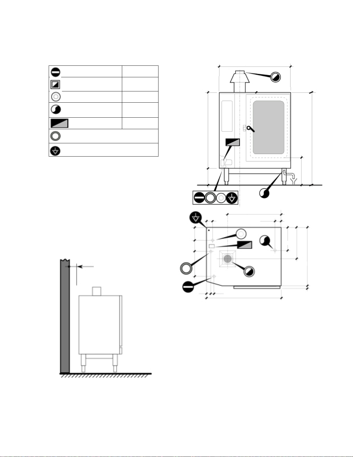
Connections
Gas inlet 3/4” NPT
Flue outlet *
Water inlet 3/4” NPT
Water drain 1 1/2”
”
Terminal Board 3 Ph
Cable gland
Ground Terminal
* The oven must be installed under a
ventilation hood only.
Not suitable for connections to type B
gas vent.
Positioning
Leave at least 4” clearance between
the rear of the appliance and the wall.
Leave at least 20” clearance at the
sides of the appliance.
9.5”
5.7”
”
22.8”
”
”
”
”
”
”
”
”
”
”
”
35”
2”
The cooling outlets of the control
section of the oven (side panel) must
not be near sources of hot fumes or
steam.
All clearance requirements are the same for combustible or noncombustible constructions. For use only on a non-combustible floor.
13
Page 14
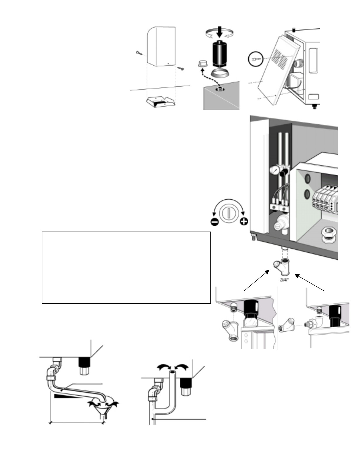
Installation
A
B
Fit the following parts
on the top of the oven:
1) Flue deflector
2) Steam vent
Water connection
3) Remove the left hand side
panel by unscrewing the two
1/4 turn screws at the bottom (if the optional
spray gun is fitted - also remove the support
screw).
4) Install the filter supplied with the unit in an
accessible position on the water inlet, as shown
in the examples below:
a) installation on TB610 frame (optional) or
other support not protruding beyond the
perimeter marked by the feet;
b) installation on other support of larger
dimensions.
The appliance must be supplied with
cold
water
Conforming to the following specifications:
Spray gun
support screw
Water
pressure
regulator
screw
Pressure
PH
: form 7 to 7.5
Conductivity
: between 40 – 80 psi
: less than 200 µS/cm
t.d.s. < 100 ppm
Hardness
Max. salinty and ion content in mg/l
: from 6.3 to 8.8 °e
:
Chlorides < 30, sulphates < 40, Fe (iron) < 0.1,
Cu (copper) < 0.05, Mn (manganese) < 0.05
The internal pressure gauge must show a pressure
of 15 psi, if it shows a different value, adjust to the
correct pressure using the regulator screw.
”
°
Water drain
CAUTION: to avoid the risk of
serious damage, the drain must be
vented
. The material of the drainage
pipe must be heat resistance type
and not flexible.
’
14
”
Page 15
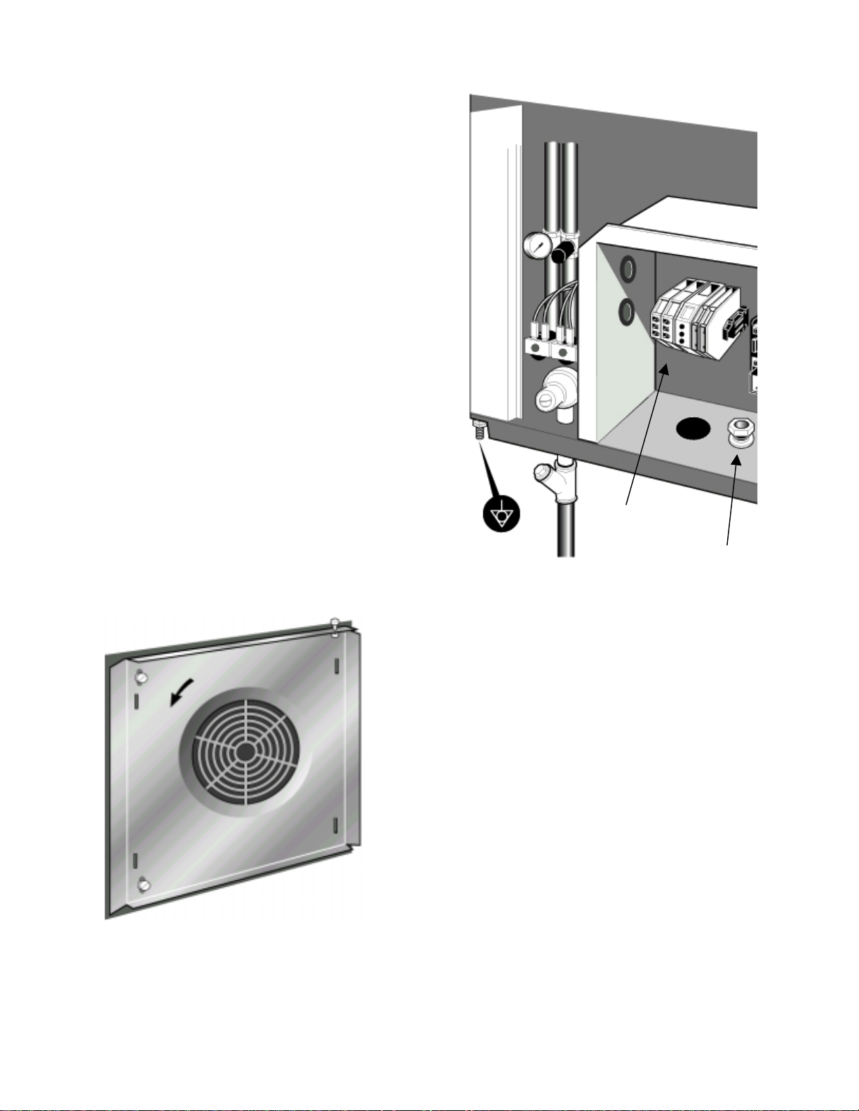
Electrical Connection
Ground Connection
The ground terminal is located
beneath the appliance at the rear
left hand corner.
Main Connection
Remove the left hand side panel.
Read the general precautionary
notes in the beginning of this
chapter.
Fit the suitable cable gland in the
relative hole.
Route the cable from the main
Power switch through the cable
gland, and connect the wires to the
terminal block.
Terminal block
Note: After making the electrical
connection, ensure the motor turns
in the direction indicated by the
arrow stamped in the baffle.
Cable gland
15
Page 16

401 units only:
Refer to the water connection section earlier in this chapter. There are two
connections on the 401 models.
Condensation Drain
Connect a suitable tube to the fitting on the condensation tray and connect to the
drainpipe.
16
Page 17
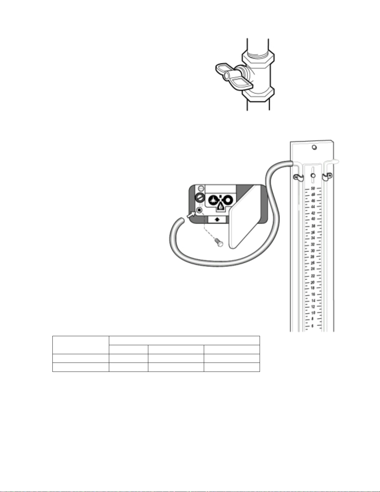
Gas pressure check
Turn the main gas valve off.
Open the door in the bottom left corner
of the unit.
Remove the cap screw of the pressure test
point and connect a pressure gauge to the
outlet.
Open the main gas valve and turn on the appliance
to maximum capacity.
Make sure the pressure lies within the limits indicated
in the table below.
Gas Type
Pressure in inches of Water Column
Rated Minimum Maximum
Natural Gas 7” 4” 10”
Propane 11” 8” 13”
After checking the gas pressure, remove the pressure gauge and close the
pressure test point.
17
Page 18
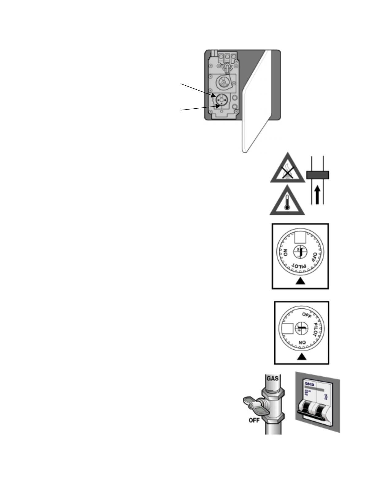
Starting the gas valve
Controls
Burner Control Knob
Reference Mark
Safety Devices
A thermocouple device locks the gas valve in case the flame is
extinguished. There is also a safety thermostat in case the
oven overheats.
Pilot flame ignition
Press the control knob and turn it to the PILOT position.
Press the knob for a few seconds and the flame will light.
Release the knob and check that the pilot flame stays on.
If it goes out wait 30 seconds and repeat instructions.
Main burner ignition
Press the control knob and turn it to the ON position.
The gas valve is now set for normal operation.
Stand-by position
To keep the burner on, with the main burner off, turn the
control knob to the PILOT position.
Turning off
Press and turn the control knob to the OFF position.
18
Page 19
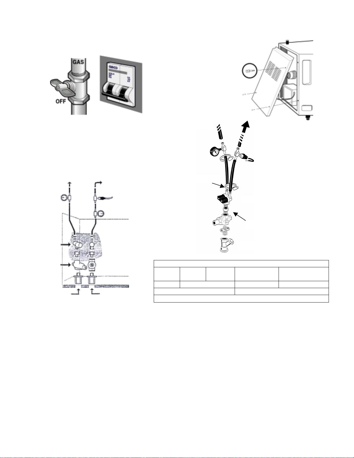
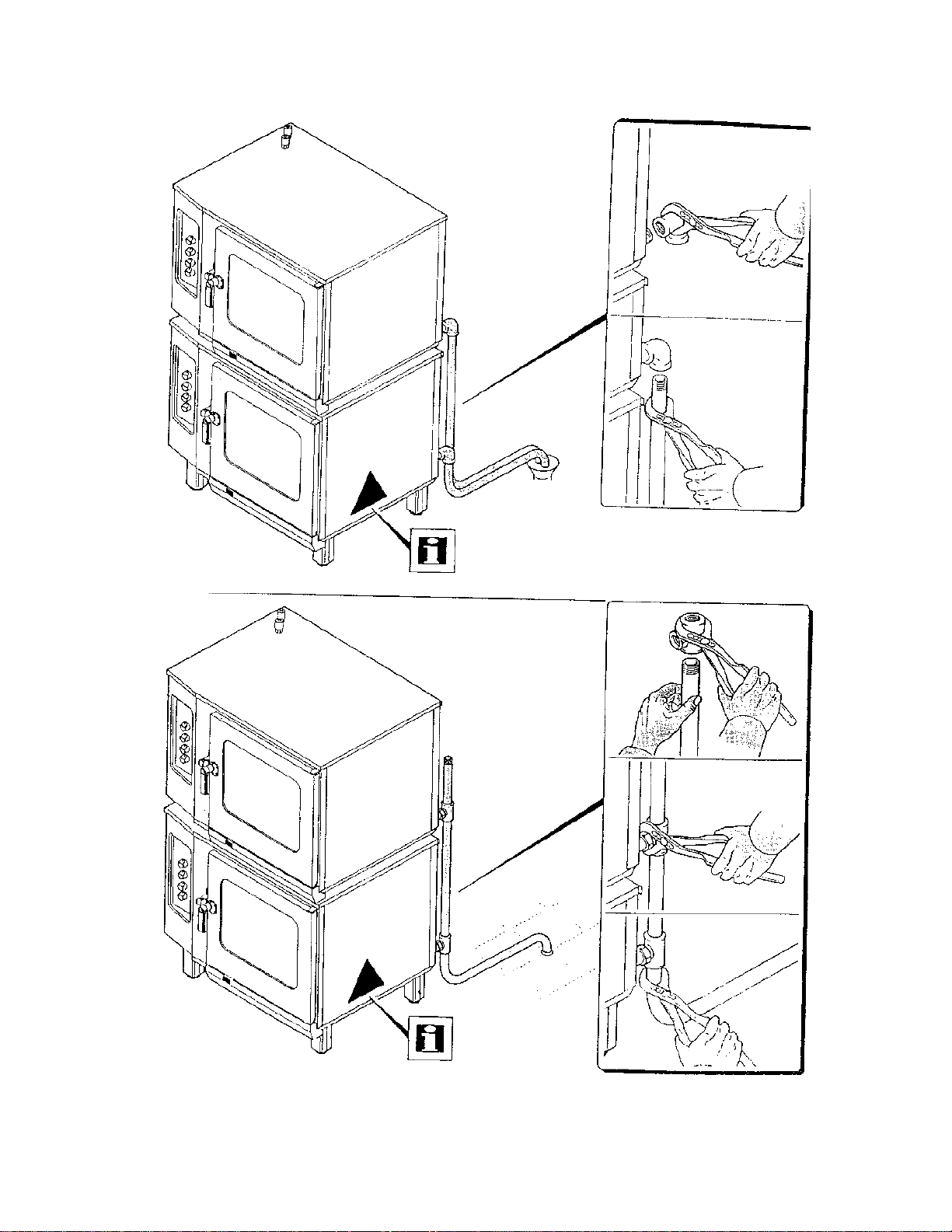
DOUBLE WATER FEED KIT
Close the gas and water supply
and cut out the main wall switch.
Remove the side Panel.
Drain
Oven Chamber
Drain
Non-Softened
Water Inlet
Oven Chamber
Bag
Hardnes
s
pH Cl < 150 mg/l SO4 < 400 mg/l Fe < 0.1 mg/l
Softened Water Inlet
Disconnect
Bag
Disconnect
Water Inlet
Water Specifications
°d
5 - 7
Mn < 0.05 mg/l Cu < 0.05 mg/l
°f
9 - 13
Conductivity < 200 µS/cm
°e
6.3 - 8.8
Softening system water consumption:
Maximum water consumption for steam is 4 gallons per hour.
Maximum water consumption for cleaning Spray Nozzle is 8 to 13 gallons per
hour.
Ppm
90 - 125
19
Page 20
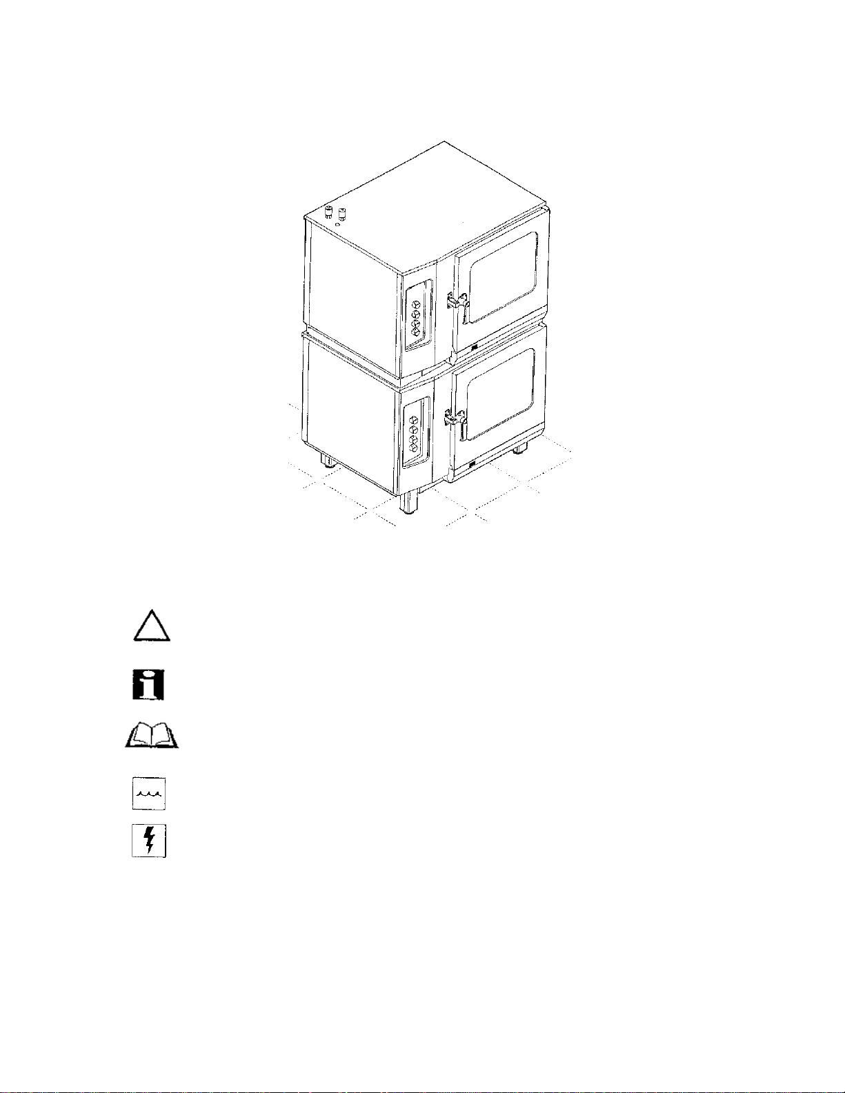
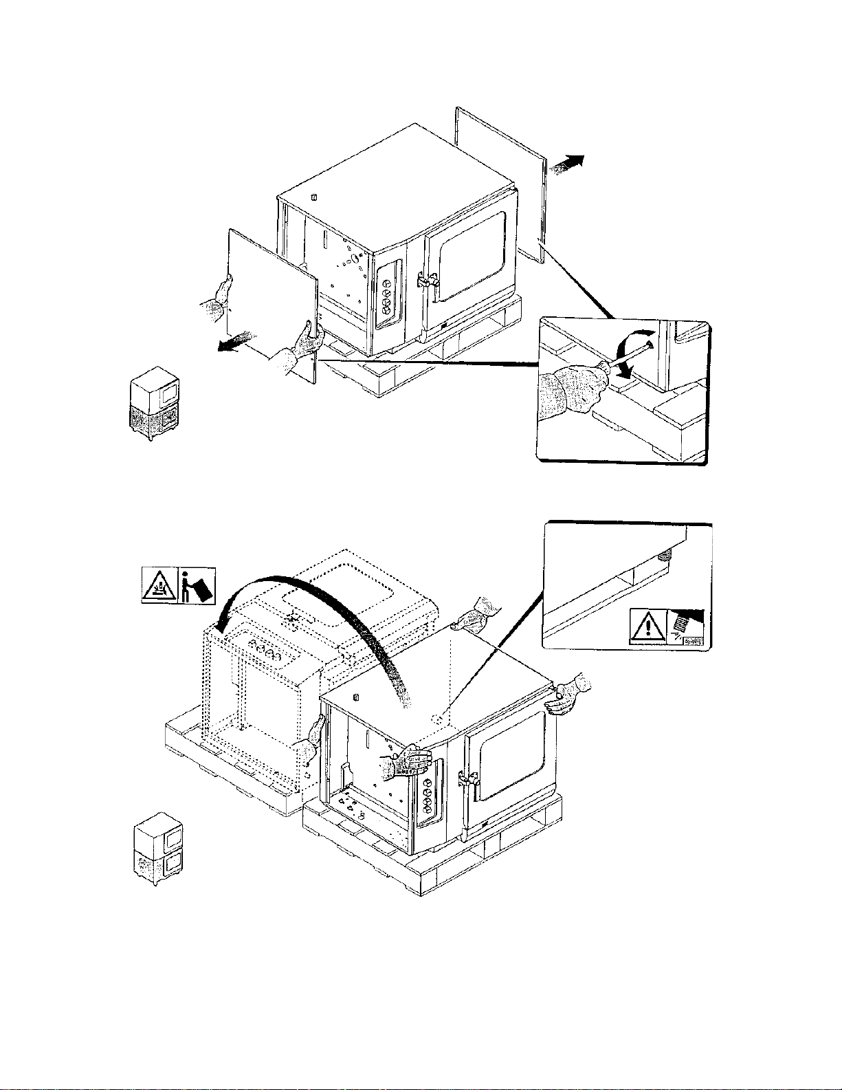
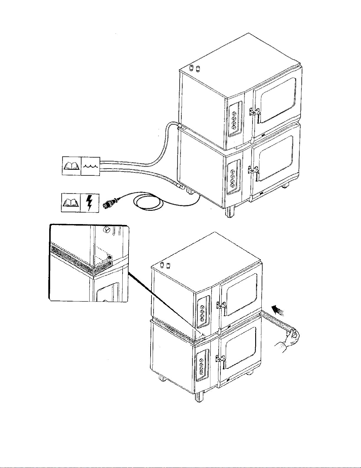
Stacking Kit Instructions
This section illustrates assembly procedures fo r the LCE 72 Only. In order to
draw particular attention to warnings and suggestions, some symbols have been
used.
Danger or Caution.
Note: Read and observe the instructions given on the appliance.
Consult the manual before carrying out connection.
Plumbing system.
Electrical system.
20
Page 21
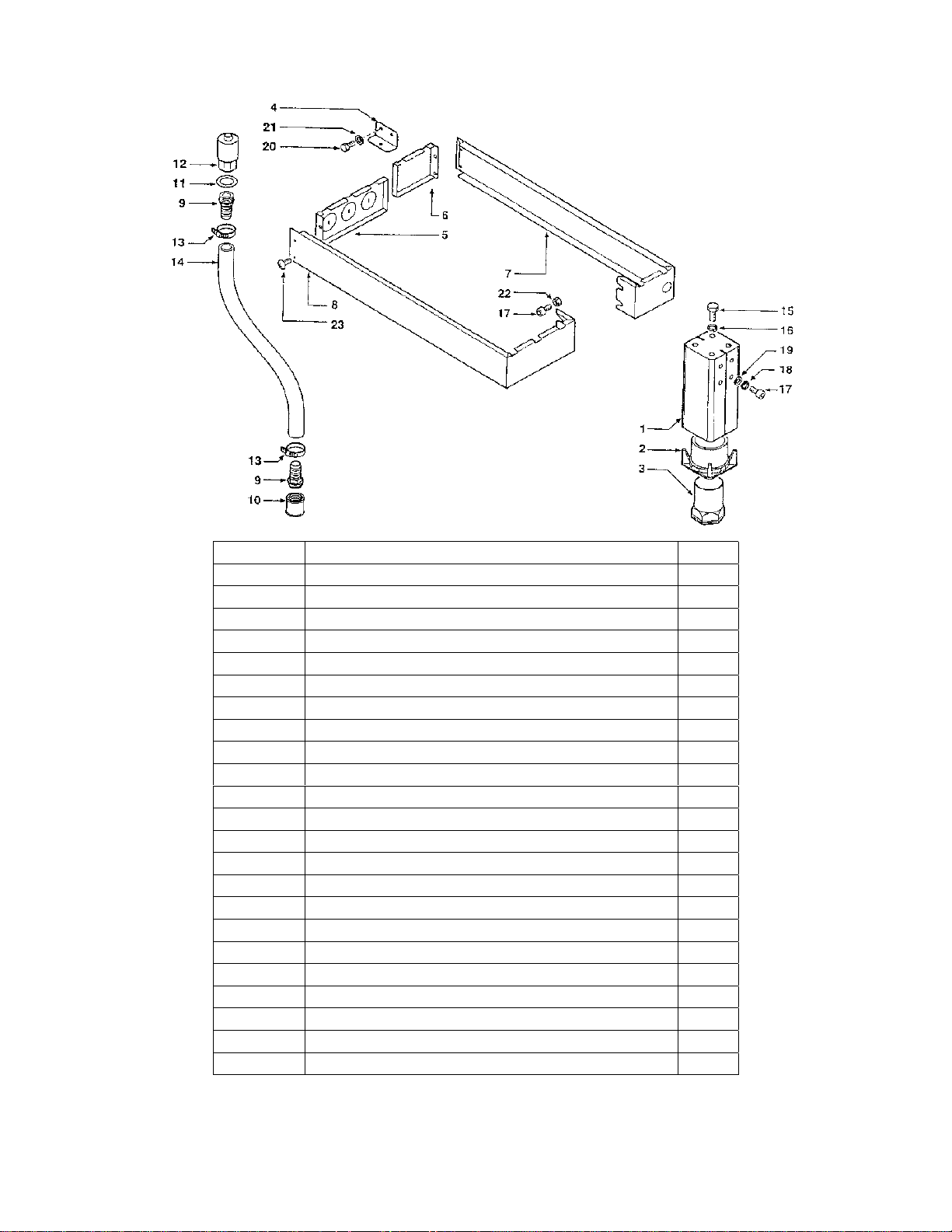
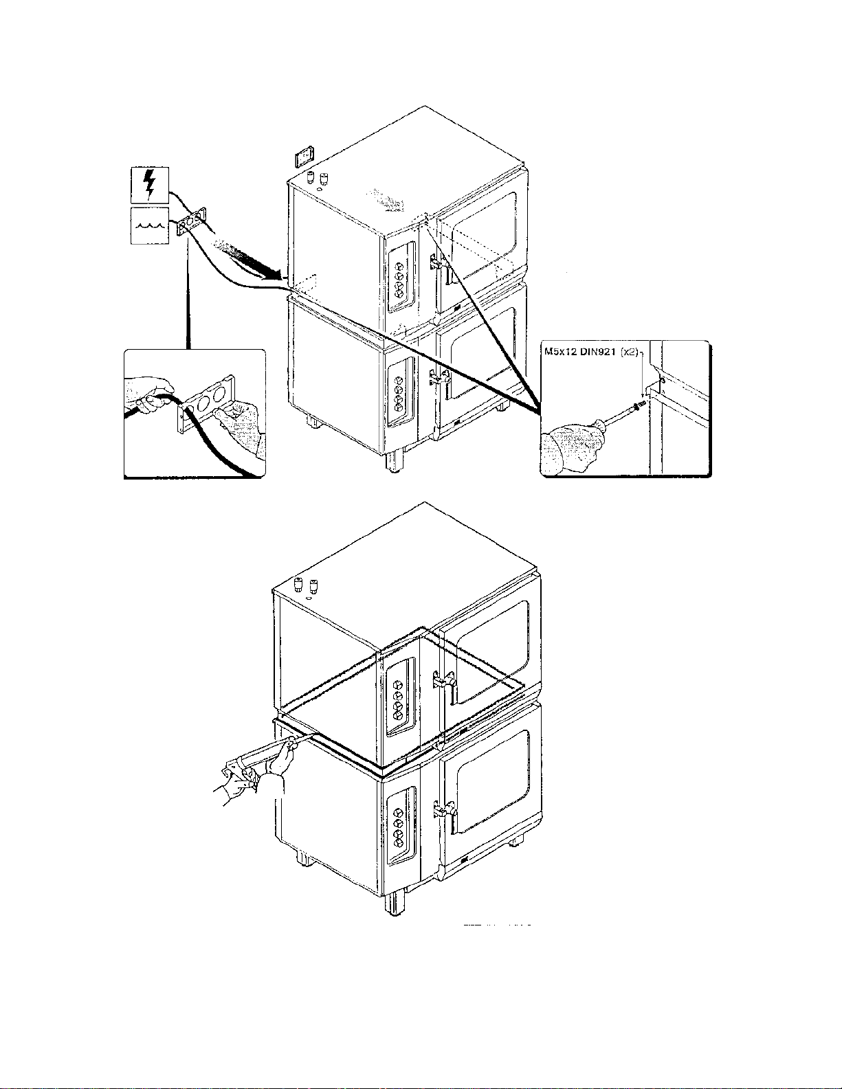
Number Description Qty.
1 Upright 4
2 Support 4
3 Foot 4
4 Bracket 2
5 Runner 1
6 Support 1
7 Right Enclosure 1
8 Left Enclosure 1
9 Connector 2
10 Pipe Coupling 1
11 Washer 1
12 Silencer 1
13 Hose Clamp 2
14 Rubber Hose 1
15 Screw 8
16 Washer 8
17 Screw 20
18 Washer 16
19 Washer 16
20 Screw 7
21 Washer 7
22 Nut 4
23 Screw 4
21
Page 22
222324252627282930
Page 23
Page 24
Page 25
Page 26

Page 27
Page 28
Page 29
Page 30
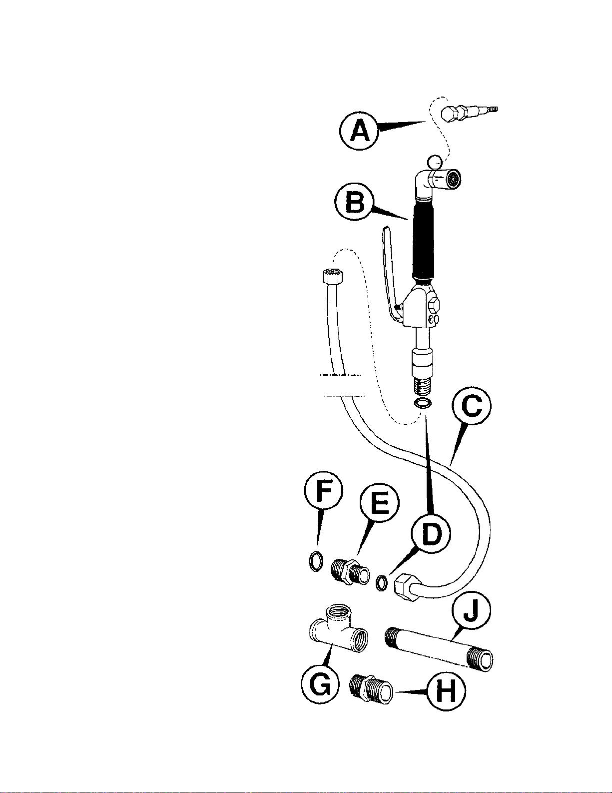
A = Supporting Screw
B = Spray Gun
C = Flexible pipe – 1/2” NPT
D = Gasket – 1/2”
E = Adapter 3/4” – 1/2”
F = Gasket – 3/4”
G = Tee 3/4”
H = Barrel Nipple 3/4”
J = Short 3/4”
Spray Hose Cleaning Kit
Page 31

31
Page 32

Spray the detergent/scale remover on all
parts of the oven/oven cavity and leave
on (if necessary, for the whole night).
Do not use descaling products
containing chlorine based
substances.
Rinse thoroughly with plenty of water.
Put the oven in steam mode for 15 minutes to
sterilize the oven. Then put the oven in
convection mode for 10 minutes to dry the unit
out.
Reassemble all parts removed and
leave the door open.
32
Page 33

OPERATION
450
400
350
485
300
0
100
150
250
33
Page 34

343536
Page 35

Page 36

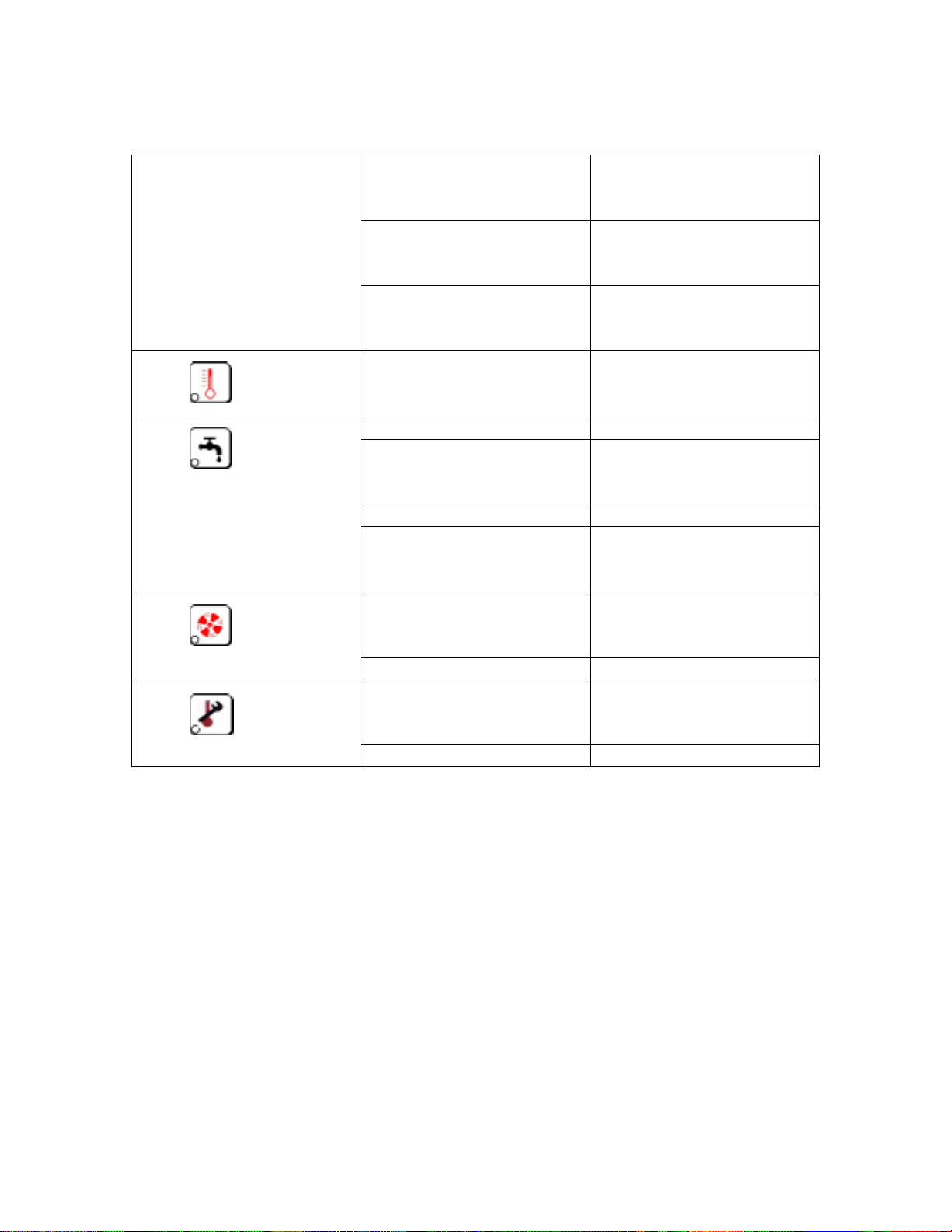
Control Panel Manual Controls
LED’s:
Excessive temperature for the
cooking method selected
Insufficient water supply pressure
Fan motor blocked (*)
Safety thermostat tripped (*)
When thes e LED’s light they always signal
an abnormal situation. Consult the trouble
shooting section.
(*) require electrical re-setting.
Power LED (Oven ON)
Oven Temperature Display
Function Select Knob
Selects the following modes of operation
400
450
350
485
300
0
100
150
250
OFF
Steam
Convection
Combi
Thermostat Knob
Regulates Oven temperature for
convection and combi mode
Timer
Sets cooking time in all three modes
Steam Control knob
Regulates steam supply during combi mode
Page 37

STEAM MODE
Preheating
Turn Knob 1 to STEAM
Turn Knob 3 to Infinity (∞)
When the temperature display shows 214 - 217°F,
place the food in the oven and set the timer for the
recommended cooking time. When this time has
elapsed, the oven will switch off and a beeper will
sound for about 30 seconds.
Malfunction indicator lights
LED
When this L ED comes on it means that the ove n
temperature is too hot for the cooking mode
selected. Once the temperature drops below
the 217°F the LED will go out.
LED
This LED will flash when the water is being supplied.
If it stays on, the oven will shut down because there
is not enough water pressure. When the pressure
returns to normal operating pressure the LED will
go out.
400
450
350
485
300
0
100
150
250
LED
When this LED lights it means th at the motor has
overheated.
LED
When this LED lights it means th at the oven has
overheated.
37
Page 38

CONVECTION MODE
Preheating
Set knob 1 to CONVECTION
Turn knob 3 to Infinity (∞)
Set the required cooking temperature on the
thermostat
When the temperature display shows the set
temperature, place the food in the oven and set the
cooking time on the timer. At the end of the cycle
the oven will shut down and a beeper will sound for
about 30 seconds.
Malfunction indicator lights
LED
This LED cannot light in this mode.
LED
This LED cannot light in this mode.
LED
When this LED lights it means th at the motor has
overheated.
400
450
350
485
300
0
100
150
250
LED
When this LED lights it means th at the oven has
overheated.
38
Page 39

COMBI MODE
Preheating
Turn knob 1 to Combi
Turn knob 3 to Infinity (∞)
Set temperature on thermostat knob 2
Set the steam level on knob 4
When the temperature display shows the set
temperature, place the food in the oven and set the
cooking time on the timer. At the end of the cycle
the oven will shut down and a beeper will sound for
about 30 seconds.
Malfunction indicator lights
LED
This LED cannot light in this mode.
LED
This LED will flash when the water is being supplied.
If it stays on, the oven will shut down because there
is not enough water pressure. When the pressure
returns to normal operating pressure the LED will
go out.
450
400
350
485
300
0
100
150
250
LED
When this LED lights it means th at the motor has
overheated.
LED
When this LED lights it means th at the oven has
overheated.
39
Page 40

Control Panel Digital Controls
STAND BY
If the oven is connected to electricity, the electronic panel switches on or off by
pushing the “Stand By” key.
Once the electronic panel has power, the cooking parameters can be set.
COOKING
Select the required cooking mode by pressing one of the following keys:
1- STEAM COOKING - temperature range: from 86°F to 217°F.
2- CONVECTION COOKING - temperature rang e: fr om 86°F to 482°F.
3- COMBINATION COOKING - temperature range: from 86°F to 482°F.
4- RETHERMALIZATION COOKING - temperature range: from 284°F to 338°F.
5- SUPERSTEAM COOKING - temper a tur e range: from 230°F to 257°F.
40
Page 41

Set the required temperature by using the up and down arrow keys. The
temperature selected will appear on the display. During the cooking cycle, the
temperature display shows the actual temperature of the oven.
The Temperature Key changes the readout from the temperature set to the
actual temperature when the cooking mode is activated, and the timer activates.
When you s elect either the combinat io n or Rethermalization Cooking Mode, the
humidity display switches on automatically.
By setting the Humidity Key,
it is possible to set the humidity inside the cooking chamber in ten degree
increments.
FOR THE PROGRAMMABLE MODELS ONLY:
With convection, combination and rethermalization cooking modes, it is
possible to select half speed fan
for delicate products by using the Half Speed Key.
The Cook ‘N’ Hold key
will automatically activate a holding temperature of 158° for 30 minutes at the
end of a cooking cycle.
41
Page 42

COOKING WITH THE TIMER
Use the Time Key to select the desired time for cooking/baking.
Use the up and down arrow keys to set the cooking time. You can read the time
set on timer display. During the cooking the timer display shows the count down
to the end of the cycle. The timer key changes the readout from count down to
set when cooking is activated.
When the cooking is finished, the heating elements automatically turn off, and an
alarm will activate for a short period of time.
Note
If the door is opened during the cooking process, not only will the heating and fan
stop, but the timer will also stop; time count-down will start from this point when
the door is closed.
When unplugged, or in the even of a power interruption, the oven will maintain
and store programs- indefinitely.
COOKING WITH THE CORE PROBE
Select the cooking with probe function by pushing the Core Probe Key.
Cooking with the probe can be utilized in any mode of cooking: steam,
convection, or combi. Set the temperature required at the center of the product
by means of up and down arrow keys. The temperature range is from 86°F to
210°F. Cooking with probe by-passes the timer, and the generation of heat is
automatically stopped as soon as the temperature of the food where the probe is
located has reached the temperature set point.
When the set point is reached, th e heating stops and the alarm will activate for
several seconds.
Note
The temperature set point can be modified during the cooking cycle by
depressing the cooking key pressed while changing the temperature using the up
and down arrow keys.
42
Page 43

FOR PROGRAMMABLE MODELS ONLY
COOKING WITH PROGRAMMING
1- STORING A SINGLE COOKING CYCLE PROGRAM IN THE COMPUTER
MEMORY:
Press the Program Key to activate the programming function.
Select a program – from P01 TO P99 using the up down arrow keys.
Select the desired cooking mode.
After setting the time or a core temperature setting, the program display will show 1-1. It
means the program is comprised of a single cooking cycle or tier: first digit = active
cooking cycle, second digit = total number of cycles or tiers in the sequence.
Push the Enter Key to store the cooking cycle program.
1- STORING A PROGRAM CONSISTING OF A SEQUENCE OF MORE THAN ONE
COOKING CYCLES OR TIERS
Push the Sequence (Tiered) Cooking Key
The display will show 2-1: the first digit indicates the running cooking cycle, the second
digit indicates the total number of cycles (tiers) included in the sequence. It is possible to
store up to 9 cycles (tiers) in a program.
Set the new program.
After having set a time or a core temperature, the display will show 2-2. This indicates
that it is the second cooking cycle of a program composed of two tiers.
Push the enter key to store the program.
Note: By pushing the time key, the time display will show the total time of the program.
3- CHANGING SETTINGS
Use the up and down arrow keys to select the program to be modified (P01 TO P99).
Use the sequence (tiered) cooking key to select the cooking program to be changed
Proceed to make the desired changes.
Push the enter key to store the data
43
Page 44

START / STOP
If you have set the cooking parameters, you can start/activate the cooking phase
by pushing the Start Key.
NOTE:
TO SET THE OVEN FOR FAHRENHEIT DEGREES, DEPRESS THE
TEMPERATURE KEY WHILE PLUGGING THE OVEN TO THE ELECTRICAL
POWER.
44
Page 45

On/Off Button
STAND-BY Button with green indicator (the applaince is connected to
power) switches the panel on or off by pushing the button.
Alarm Lights
Failure code (E1 to E7), see troubleshooting section.
Flashing Red
Chamber is too hot for steam mode.
Flashing Red
Failure in water pressure, it will light with the display saying E6 or E7.
Red Light
Oven has been used for five hours, routine cleaning is recommended.
Cooking Mode Buttons
Steam Mode.
Green light shows when selected (Temp. 86 - 217°F).
Convection Mode.
Green light shows when selected (Temp. 86 - 482°F).
Combination Mo de.
Green light shows when selected (Temp. 86 - 482°F).
Regeneration Mode.
Green light shows when selected (Temp. 284 - 338°F).
Supersteam Mode.
Green light shows when selected (Temp. 230 - 257°F).
Up / Down Buttons
Increase or decrease set value.
Operating Controls
Steam Percentage Control.
Sets humidity level.
Temperature Control.
Changes readout from set to active.
Cooking Time Control.
When cooking is activated, changes re adout from cou nt-down to set .
45
Page 46

Core Temperature Control.
Changes readout from set to active.
Start / Stop Button
During the cooking phase this green light flashes.
Using the Oven
At the start of each cooking session we advise preheating the oven by running a
short cooking cycle when the oven is empty. At the end of the cycle the oven will
automatically stop and an buzzer will sound for 30 seconds.
Cooking
Select the required cooking mode by pressing one
of the following keys: 6 (STEAM), 7 (Convection),
8 (Combi), 9 (Regeneration), 10 (Supersteam)
Set the required chamber temperature using
arrow-keys 15.
Note: When cooking in modes 8 or 9 (Combi or
Regeneration) it is possible to set the steam.
2
1
9876
543
10
Cooking with the timer
Select the cooking timer by pressing 17
Use the arrow keys 18 to set the cooking time on
the display 16. Start the cycle using button 22
(START/STOP), the timer display will show the
count-down time. When the cooking is finished,
the buzzer will sound for 30 seconds.
Cooking with the core temperature probe
Use button 20 to select the core probe.
Set the temperature required at the center of
the product by using the arrow keys 21.
Start the cycle using button 22 (START/STOP).
When the cooking is finished, the buzzer will
sound for 30 seconds.
Note: when the probe is activated and reaches
the set temperature the oven will stop cooking.
11
19
1413
20
22
12
15
181716
21
46
Page 47

Changing setting during cooking
The value set can be modified during the cooking phase by keeping the cooking
key pressed while modifying the display using keys 15, 18, or 21.
To modify the values of a cooking program different from the one being used,
keep the relevant key pressed and proceed to modify as necessary using keys
15, 18, or 21.
Note: time changes during cooking will affect only the time remaining.
Note: If the door is opened while cooking is in process, not only will the heat and
the fan stop, but the timer will stop also. The timer will resume once the door is
closed.
When unplugged, the unit will store the programs indefinitely.
The core temperature probe can be set in any mode (Combi, Convection, Steam,
Regeneration, Super steam). It does not use the timer when in this mode.
47
Page 48

CLEANING
Turn the unit off.
Allow the unit to cool to at least 140°F.
Remove the racks from the oven.
Daily Cleaning
Drip Tray
The drip tray must be emptied and cleaned
frequently. If it is connected to a drainage
outlet, check that the outlet hole is not
clogged.
Cooking Chamber
Remove the rack slide from the cooking
chamber.
Remove the filter strainer from the bottom
of the oven chamber and clean it.
Spray detergent (detergent without chloride
or chlorine, specific for stainless steel) on
the walls of the unit using the special
detergent spray unit.
Wait 30 minutes.
Rinse thoroughly with water.
Heat the oven in steam mode for 15
minutes.
Heat the oven in convection mode for 15
minutes.
If the unit is not going to be used again until
tomorrow, leave the door partially open all
night.
MAINTENANCE & CLEANING
Yearly
The under-pressure valve #9 will need to be cleaned and checked for proper
operation.
48
Page 49

Cleaning functional parts of the oven
De-scaling the blower wheel
The blower wheel must be de-scaled every 15
days.
Remove the racks and rack slides.
Unscrew the two screws securing the baffle to
the oven, and open the baffle.
De-scale the blower wheel with a suitable descaling agent.
For thorough cleaning of the blower wheel
Unscrew the atomizer while keeping the blower
wheel from turning and loosen the two set
screws on the motor shaft.
Screw the supplied extractor bolt into the shaft
until the blower wheel is disengaged from the
shaft.
Note: When reassembling the fan, ensure the
blower wheel is seated fully on the shaft before
tightening the set screws.
Cleaning the water filter
Close the main water supply valve, unscrew
the plug, and remove the filter and clean it.
Cleaning the drain siphon (located beneath the
oven)
Unscrew the plug and remove any
accumulated debris.
Note: Limescale deposits must be removed regularly, especially from the heat
exchanger. When the scale film becomes thick, it is either very difficult or
impossible to remove. Limesca le is a thermal insulating material. W hen the
scale film on the heat exchanger becomes too thick, heat exchanging is impeded
causing the pipes and the combustion chamber to overheat and possibly break.
Limescale is porous and absorbs grease and odors that might be released later.
49
Page 50

MAINTENANCE
WARNING: DISCONNECT THE UNIT’S
POWER FROM THE WALL BEFORE
PROCEEDING WITH ANY OF THESE
PROCEDURES.
Replacing light bulbs or the light glass
Remove the left hand side panel by unscrewing
the 1/4 turn screws.
Unscrew the screw and nut shown in the figure
and remove the lamp-holder.
Replace the bulb.
To remove the light glass for replacement,
unscrew the other three nuts inside the lampholder and remove the glass.
Replacing fuses
Remove the left hand side panel.
The plug-in type fuses holders are located at
the side of the terminal board. Replace with
rapid-acting fuses.
Resetting overload cut-outs
The overload cut-out, disconnects the power
supply to the motor when it overheats due to
overload.
Before pressing the reset button, find and
eliminate the cause of the overload.
Resetting the safety thermostat
The safety thermostat shuts down the oven
when internal temperatur e ex ceeds 572°F.
To restart the oven:
Remove the left hand panel.
Allow the oven to cool for about 10 minutes,
find and correct the cause of overheating
and then press the reset button.
Electrical
Diagram
50
Page 51

GAS CONVERSIONS
WARNING: ENSURE THE MAIN GAS
VALVE IS TURN OFF BEFORE
PROCEEDING.
Replacement of Injectors
The injectors are reachable through
the bottom of the oven. Remove the
drip tray.
Unscrew each injector and replace it
with the one suitable for the type of
gas at your location.
Replacement of Pilot Flame Injector
Unscrew cap A, unscrew injector B
and replace it as necessary for the
type of gas at your locat ion.
After replacing the injector, turn on
the pilot flame and adjust the primary
air nut as necessary.
Air
Regulation
Ring
51
Page 52

Adjustments to the gas valve
NATURAL GAS
Remove screw A from the pressure connection
and connect a pressure gauge.
PROPANE
Remove the plug B and check if
it matches with detail E. If
positive screw it completely, if
not remove screw C, spring
D
and replace them with plug E.
Remove the plug B and ensure the adjustment
screw C is there, otherwise insert the spring
D
with the screw C.
Start the burner and adjust the screw C until
the pressure gauge shows the correct reading.
After having checked that the flame is stable,
stop the burner, disconnect the pressure
gauge, screw the plug B in completely, seal
the adjustment screw C with a drop of paint
and replace plug
B.
52
Page 53

PROBLEMS POSSIBLE CAUSES SOLUTIONS
Power is on, display or
LED is not on.
Power is on, lights in the
cooking chamber do not
work.
Start-button pressed, no
water flow for cooling
system.
Start-button pressed, no
fan, no burner or
elements.
Start-button pressed, fan
works, no burner or
elements.
GAS UNIT ONLY:
Spark ignition of pilot
flame is out of wo rk.
Fuses F3-F4 are blown.
Light Bulbs are burnt out.
Fuses F1-F2 are blown.
Solenoid valve (6) is not
energized.
Solenoid valve coil is
burnt.
Door does not activate
microswitch.
Fuse F1 is blown.
Door does not activate
microswitch.
Microswitch is not
working.
Fuse F1 or F2 is blown.
Gas valve or heating
elements are burnt.
GAS UNITS ONLY:
Low voltage transformer
(or its fuse) is blown.
Gas valve switch is
button is not working.
Spark igniter is broken.
High voltage spark cable
is damaged.
TROUBLESHOOTING
Check power.
Check fuses near the
terminal block.
Check light bulbs.
Check fuses.
Clean or de-scale
solenoid valve.
Replace coil.
Replace solenoid valve.
Check door hinges.
Replace microswitch.
Check fuse F1.
Check that the door
closes properly.
Replace microswitch.
Check fuses F1 & F2.
Check gas flow.
Check gas valve.
Check low voltage
transformer and its fuse.
Replace switch button.
Replace spark igniter.
Replace High voltage
cable.
53
Page 54

GAS UNITS ONLY:
Air in the pilot flame pipe. Repeat ignition
Pilot flame can not be
ignited.
GAS UNITS ONLY:
Pilot flame estinguishes.
Start-button pressed, No
steam.
Thermocouple bulb is
dirty or damaged.
Solenoid valve (7) is
energized but is
defective.
Solenoid coil is burnt.
Scale has obstructed
water.
Water pressure regulator
is wrong.
Water nozzle (19) is
obstructed.
Fuse F1 is blown.
Start-button pressed, unit
steams when no steam is
selected.
Scale built up in the
solenoid valve (7).
Solenoid valve is
defective.
Start-button pressed,
steam is not at the set
level (too much or too
little).
Thermostat controlling
temperature of the
condensation tube is
defective.
Cooling water nozzle (10)
is obstructed.
Solenoid valve (6) is
obstructed or defective.
Inconsistent Cooking. Motor is spinning in the
wrong direction.
Noises from the trap. Drain (16) is obstructed
or not ventilated.
Silencer (17) is
obstructed by a rag or
pan.
Cooling water nozzle (10)
is obstructed.
procedure several times
to bleed the air out.
Clean or replace the
thermocouple.
Disassemble solenoid
valve (7) and clean or descale.
Replace coil.
De-scale water pipe.
Set water pressure
regulator properly.
Clean water nozzle.
Check fuse F1.
Disassemble solenoid
valve (7) and de-scale.
Replace solenoid valve
or its coil.
Replace thermostat
controlling tempe r ature of
the condensation tube.
Disassemble and clean
or de-scale water nozzle
(10).
Disassemble solenoid
valve and clean or descale.
Replace coil or solenoid
valve.
Change the motor phase.
Verify and clean drain
(16), or proved adequate
venting.
Keep silencer free.
Disassemble cooling
water nozzle (10) and
clean or de-scale.
54
Page 55

WORKING MODES
Device Steam / Super-steam Convection Combi
Solenoid valve
(7)
Permanently
energized.
Permanently
energized.
Alternately
energized / de-
energized.
Calibrated quantity of
water through pipe
(11) by means of
pressure regulator
(14) and nozzle (19).
Variable quantity
of water according
to set percentage.
Duty cycle is 5
sec. on 9 sec. off.
Nozzle (19)
61 = .5
101 = .6
141 = .7
241 = .7
401 = .7
22
21
23
Contr o l formula for
humidity %.
10% = 122°F
20% = 131°F
30% = 140°F
40% = 149°F
50% = 158°F
60% = 167°F
18
19
20
70% = 176°F
80% = 185°F
90% = 194°F
Solenoid valve
(6)
Permanently
energized.
Calibrated quantity of
water to cool down
drain system by
means of the pressure
regulator (14) and
nozzle (10).
Permanently
energized.
Calibrated
quantity of water
to cool down
drain system by
means of t he
pressure
regulator (14) and
nozzle (10).
55
Permanently
energized.
Calibrated
quantity of water
to cool down drain
system by means
of the pressure
regulator (14) and
nozzle (10).
Page 56
ALARMS FOR THE MANUAL CONTROL COMBI’S
The power LED lights but
the temperature display
does not show any
change in temperature.
LED Lights
LED Lights
LED Lights
LED Lights
Knob 1 (page 36) has not
been set to a cooking
Turn in to a cooking
mode.
mode.
Timer Knob 3 (page 36)
has not been set to a
Set any time higher than
zero.
cooking time.
Thermostat knob 2 (page
36) has not been set.
In convection or Combi
cooking, the temperature
must be set.
You switched from
CONVECTION or COMBI
cooking to steam.
Wait until the oven
temperature drops to 214
- 218°F.
No water supply. Call your local plumber.
Insufficient water
pressure.
Contact your water dept.
to increase your water
pressure.
Faulty solenoid valve. Call your local servicer.
Water control valve out of
calibration.
Your local servicer
should calibrate the
valve.
One of the phases is
missing.
Check electrical
connection and reset as
described on page 50.
Motor blocked. Call your local servicer.
Oven has momentarily
overheated.
Wail unit it cools down
and rest as described on
page 50.
Faulty Thermostat. Call your local servicer.
56
Page 57

ALARMS FOR THE DIGITAL CONTROL COMBI’S
When this indicator lamp fla shes the oven c hamber temper ature is too high for the
selected cooking mode. This lamp will light whenever you change from a high
temperature cooking mode (Convection or Combi) to a lower temperature mode
(214 - 218°F Steam, 284 - 338°F Rethermalization mode, 230 - 257°F for SuperSteam). When this lamp is illumin ated heating is stopped until the temperature falls
to within the permissible range. The lamp will then turn off and the oven will
operate normally.
Note: This lamp should not illuminate during convection or combi modes.
This lamp flashes to indicate water supply problems (either due to a temporary
interruption of the supply or a drop in water pressure). If this occurs during a
Steam, Re-thermalization, or Super-Steam, oven heating is immediately stopped.
At this point press START to check whether the problem is still present. If the lam p
continues to flash (and the water supply is OK) check for the possible causes. If
the lamp starts flashing during the Convection or Combi cooking, the oven will
continue to operate normally and the indicator lamp will switch off as soon a s
normal conditions are restored.
Illuminates after 5 hours of cooking to signal that the cleaning procedures should
be completed. The oven continues to operate. Pressing the START-STOP key
switches off the indicator lamp and the hours of cooking count restarts from zero.
This display will show an alarm code to help identify the cause of the
problem. You can remedy it by following the instructions in the chart
below.
Alarm Codes
000
flashing
00
flashing
LED flashes
LED flashes
or - - -
or - -
Faulty cooking chamber temperature probe.
If core temperature probe is not skewered in
food and the oven chamber is at ambient
temperature: core temperature probe is
faulty.
You have switched from convection or
combi mode operation to steam mo de.
Then unit must cool down.
Main water supply was interrupted or the
pressure is too low.
Water flow control valve is incorrectly set.
57
Page 58

Display shows the following
Codes:
LED flashes
E1
E2
E3
E4
E5
E6
E7
E8
Faulty oven chamber temperature probe.
Faulty core temperature probe.
Faulty steam discharge temperature probe.
Motor thermal trip.
Safety thermostat trip.
Faulty oven chamber pressure switch.
Faulty drain pressure switch.
Faulty oven chamber lower probe.
Oven has been in effective use for 5 hours.
00
or - -
flashing
TO CHECK CIRCUIT BOARD INPUT/OUTPUT ON DIGITAL MODELS
Make sure the unit is plugged in.
If any pre-set value is shown on the displays, press push-button
as to get “STAND-BY condition.
Keep both push-buttons “TIME” and “START” simultaneously
pressed for about 5 seconds, until a “beep” sounds. This operation does not
change or clear any pre-set value. It allows the operator to check all input/output
relays and the relevant connected remote switches. By pressing all the pushbuttons from the top (left to right), the relevant LED light switches on, while a
relay is energized. According to the circuit board type, an opportunity is given to
energize one of the relays.
A progressive number, corresponding to the pressed pu sh-button, will be shown
on the display. This allows us to verify all circuit board input, both from the digital
pad, from outside switches (i.e. pressure switches etc.) and from inputs at
120/208V (i.e. door micro-switches and safety thermostats).
To get out from this program, keep again the above mentioned push-buttons
pressed until a beep sounds.
Faulty steam discharge temperature probe.
58
Page 59

TO CHECK THE PT100 PROBE IN THE CONDENSATION TUBE ON DIGITAL
MODELS
This can be done while the unit is cooking.
Keep both push-buttons “TIME” and “TIME DOWN”
Simultaneously pressed.
This operation does not change or clear any pre-set value of the circuit board. It
allows the operator to verify the humidity level in the oven by display the
temperature in the condensation tube.
10% = 122°F
20% = 131°F
30% = 140°F
40% = 149°F
50% = 158°F
60% = 167°F
70% = 176°F
80% = 185°F
90% = 194°F
59
Page 60
TECHNICAL DATA
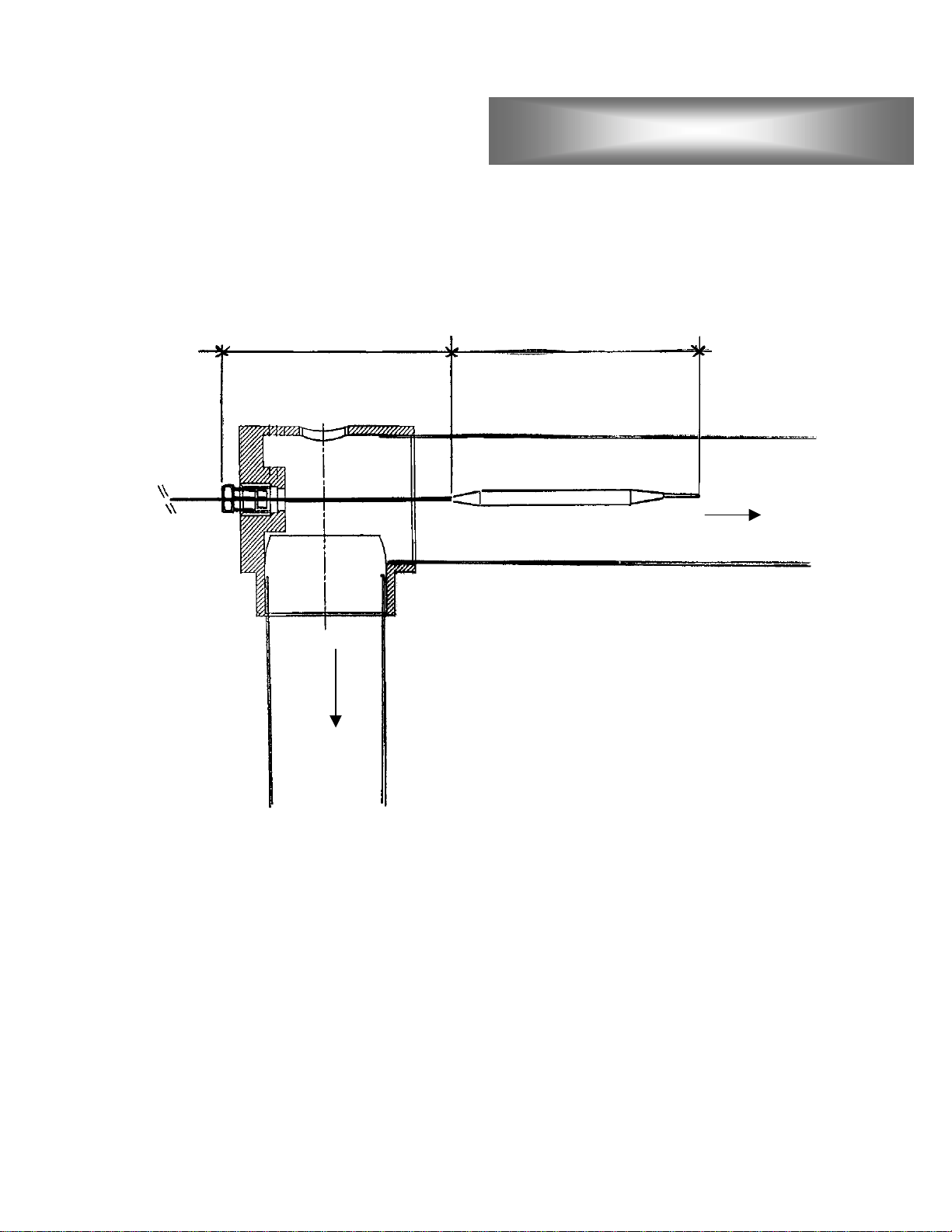
Total distance from A to B for all digital models is 5 5/16”.
Total distance from A to B for mechanical models is:
8 11/16” for models LC-61, 72, & 101
10 7/16” for models LC-141, 241, & 401
Drain Temp. Detecting Probe
To the cooking
chamber
To the
drain
60
Page 61

PT-100 Temperature Probe
White
Red
Red
White
Red
Red
61
Page 62

PT-100 resistance chart
Temp. Resistance Temp. Resistance Temp. Resistance
0°F 93.04 Ω 185°F 132.79 Ω 370°F 171.33 Ω
5°F 94.13 Ω 190°F 133.85 Ω 375°F 172.36 Ω
10°F 95.22 Ω 195°F 134.90 Ω 380°F 173.38 Ω
15°F 96.31 Ω 200°F 135.96 Ω 385°F 174.41 Ω
20°F 97.39 Ω 205°F 137.01 Ω 390°F 175.43 Ω
25°F 98.48 Ω 210°F 138.07 Ω 395°F 176.45 Ω
30°F 99.57 Ω 215°F 139.12 Ω 400°F 177.47 Ω
35°F 100.65 Ω 220°F 140.17 Ω 405°F 178.49 Ω
40°F 101.73 Ω 225°F 141.23 Ω 410°F 179.51 Ω
45°F 102.82 Ω 230°F 142.28 Ω 415°F 180.53 Ω
50°F 103.90 Ω 235°F 143.33 Ω 420°F 181.55 Ω
55°F 104.98 Ω 240°F 144.37 Ω 425°F 182.56 Ω
60°F 106.06 Ω 245°F 145.42 Ω 430°F 183.58 Ω
65°F 107.14 Ω 250°F 146.47 Ω 435°F 184.59 Ω
70°F 108.22 Ω 255°F 147.52 Ω 440°F 185.61 Ω
75°F 109.30 Ω 260°F 148.56 Ω 445°F 186.62 Ω
80°F 110.38 Ω 265°F 149.61 Ω 450°F 187.63 Ω
85°F 111.45 Ω 270°F 150.65 Ω 455°F 188.64 Ω
90°F 112.53 Ω 275°F 151.69 Ω 460°F 189.65 Ω
95°F 11.60 Ω 280°F 152.73 Ω 465°F 190.66 Ω
100°F 114.67 Ω 285°F 153.77 Ω 470°F 191.67 Ω
105°F 115.75 Ω 290°F 154.81 Ω 475°F 192.68 Ω
110°F 116.82 Ω 295°F 155.85 Ω 480°F 193.68 Ω
115°F 117.89 Ω 300°F 156.89 Ω 485°F 194.69 Ω
120°F 118.96 Ω 305°F 157.93 Ω 490°F 195.69 Ω
125°F 120.03 Ω 310°F 158.97 Ω 495°F 196.70 Ω
130°F 121.10 Ω 315°F 160.00 Ω 500°F 197.70 Ω
135°F 122.16 Ω 320°F 161.04 Ω 505°F 198.70 Ω
140°F 123.23 Ω 325°F 162.07 Ω 510°F 199.70 Ω
145°F 124.30 Ω 330°F 163.10 Ω 515°F 200.70 Ω
150°F 125.36 Ω 335°F 164.13 Ω 520°F 201.70 Ω
155°F 126.42 Ω 340°F 165.17 Ω 525°F 202.70 Ω
160°F 127.49 Ω 345°F 166.20 Ω 530°F 203.70 Ω
165°F 128.55 Ω 350°F 167.23 Ω 535°F 204.70 Ω
170°F 129.61 Ω 355°F 168.25 Ω 540°F 205.69 Ω
175°F 130.67 Ω 360°F 169.28 Ω 545°F 206.69 Ω
180°F 131.73 Ω 365°F 170.31 Ω 550°F 207.68 Ω
62
Page 63

Water consumption table
Oven
Model
LC-61 .5 mm 14.5 psi 2 gal 28 gal 10 gal
LC-101 .6 mm 14.5 psi 3 gal 28 gal 30 gal
LC-72 .7 mm 14.5 psi 5 gal 28 gal 33 gal
LC-141 .7 mm 14.5 psi 5 gal 28 gal 33 gal
LC-241 .7 mm 14.5 psi 5 gal 28 gal 33 gal
LC-401 2 x .7 mm 14.5 psi 2 x 5 gal 2 x 28 gal 66 gal
Injector
Size
Water
Pressure
Water to
steam
Water to
drain
Total
Water Qty.
63
Page 64

MODEL LANG COMBI ELECTRIC: LCE-61
64
PAN CAPACITY Maximum 6 Full Size Sheet Pans
6 Full Size Steam Table Pans
Optimum 6 Full Size Sheet Pans
4 Full Size Steam Table Pans
INTERIOR 20 Gauge Stainless Steel Critical Components, 316 Stainless
Interior, 304 Stainless
Inside Oven Dimensions
(W x D x H): 24" x 24 5/8" x 17 29/32"
(610mm x 620mm x 450mm)
2 Oven Lights
1 Oven Drain Screen
1 Removable Drip Tray
Stainless Steel Rack Frame With 6 Support Rails
6 Stainless Steel Oven Racks
EXTERIOR 20 Gauge Stainless Steel
Outside Dimensions (Height Includes Legs)
(W x D x H): 371/2" x 29" x 311/2"
(950mm x 740mm x 800mm)
ELECTRICAL 208 and 240 Volt AC, 50/60 Hz, 3 Phase
Total kW: 9.5 kW
Amperage Per Line
• 208 / 3 Phase: 26.4 Amp/Phase
• 240 / 3 Phase: 22.8 Amp/Phase
Terminal Block Connection
WATER Cold Water Intake Size:
Water Pressure: 40 psi Min, 80 psi Max
Water Consumption: 30 Gal/Hr (113 Liters/Hr)
3
/4" NPT
S P E C I F I C AT I O N S
DRAIN Vented Drain Required
Drain Size: 11/2" NPT
WEIGHT Shipping Weight (Crated): 353 lb (160 kg)
Net Weight (Uncrated): 309 lb (140 kg)
INSTALLATION Legs 4" (100mm) Included
Vent Hood Check Local Codes
Water Shut Off Valve Check Local Codes
Water Back Flow Preventer Required
Minimum Clearances Required
• Sides (Includes Service Access): 20" (500mm)
• Back: 4" (100mm)
• Counter Top: 4" (100mm)
ACCESSORIES Water Wash Down Hose Included (Part Number LDL)
Plastic Detergent Spray Bottle Included (Part Number PND)
Stainless Steel Oven Rack 6 Included (Part Number G610X)
OPTIONS Control Options: Manual Dial (M)
Digital (D)
Digital Programmable (DP)
Stainless Stand: TB610P
Stainless Stand With Bottom Shelf: TB610
Stainless Roll In Rack Frame, 6 Position: SRG6 (Standard Spacing)
Stainless Roll In Rack Frame, 4 Position: SRG685
Guides For Roll In Rack: GSR610
Rack Frame Transport Trolley: C610
U
L
N S F
U SC
®
Page 65

MODEL LANG COMBI ELECTRIC: LCE-101
65
PAN CAPACITY Maximum 10 Full Size Sheet Pans
10 Full Size Steam Table Pans
Optimum 10 Full Size Sheet Pans
8 Full Size Steam Table Pans
INTERIOR 20 Gauge Stainless Steel Critical Components, 316 Stainless
Interior, 304 Stainless
Inside Oven Dimensions (W x D x H): 24" x 24 5/8" x 27 3/8"
(610mm x 620mm x 690mm)
2 Oven Lights
1 Oven Drain Screen
1 Removable Drip Tray
Stainless Steel Rack Frame With 10 Support Rails
EXTERIOR 20 Gauge Stainless Steel
Outside Dimensions (Height Includes Legs)
(W x D x H): 371/2" x 29" x 41"
(950mm x 740mm x 1030mm)
ELECTRICAL 208 and 240 Volt AC, 50/60 Hz, 3 Phase
Total kW: 17.9 kW
Amperage Per Phase
• 208 / 3 Phase: 49.7 Amp/Phase
• 240 / 3 Phase: 43.1 Amp/Phase
Terminal Block Connection
WATER Cold Water Intake Size:
Water Pressure: 40 psi Min, 80 psi Max
Water Consumption: 31 Gal/Hr (117 Liters/Hr)
3
/4" NPT
S P E C I F I C AT I O N S
DRAIN Vented Drain Required
Drain Size: 11/2" NPT
WEIGHT Shipping Weight (Crated): 386 lb (175 kg)
Net Weight (Uncrated): 364 lb (165 kg)
INSTALLATION Legs 4" (100mm) Included
Vent Hood Check Local Codes
Water Shut Off Valve Check Local Codes
Water Back Flow Preventer Required
Minimum Clearances Required
• Sides (Includes Service Access): 20" (500mm)
• Back: 4" (100mm)
• Counter Top: 4" (100mm)
ACCESSORIES Water Wash Down Hose Included (Part Number LDL)
Plastic Detergent Spray Bottle Included (Part Number PND)
OPTIONS Control Options: Manual Dial (M)
Digital (D)
Digital Programmable (DP)
Stainless Steel Oven Rack: G610X
Stainless Roll In Rack Frame, 10 Position: SRG10 (Standard Spacing)
Stainless Roll In Rack Frame, 7 Position: SRG1085
Stainless Stand: TB610P
Stainless Stand With Bottom Shelf: TB610
Rack Frame Transport Trolley: C610
Guides For Roll In Rack: GSR610
U
L
N S F
U SC
®
Page 66

MODEL LANG COMBI ELECTRIC: LCE-72
66
PAN CAPACITY Maximum 7 Full Size Sheet Pans
14 Full Size Steam Table Pans
Optimum 7 Full Size Sheet Pans
10 Full Size Steam Table Pans
INTERIOR 20 Gauge Stainless Steel Critical Components, 316 Stainless
Interior, 304 Stainless
Inside Oven Dimensions (W x D x H): 33" x 32 1/2" x 22 1/32"
(840mm x 830mm x 560mm)
2 Oven Lights
1 Oven Drain Screen
1 Removable Drip Tray
7 Stainless Steel Racks
Stainless Steel Rack Frame With 7 Support Rails
EXTERIOR 20 Gauge Stainless Steel
Outside Dimensions (Height Includes Stand)
(W x D x H): 461/2" x 371/2" x 63"
(1180mm x 940mm x 1500mm)
ELECTRICAL 208 and 240 Volt AC, 50/60 Hz, 3 Phase
Total kW: 17.9 kW
Amperage Per Phase
• 208 / 3 Phase: 49.7 Amp/Phase
• 240 / 3 Phase: 43.1 Amp/Phase
Terminal Block Connection
WATER Cold Water Intake Size:
Water Pressure: 40 psi Min, 80 psi Max
Water Consumption: 33 Gal/Hr (124 Liters/Hr)
3
/4" NPT
S P E C I F I C AT I O N S
DRAIN Vented Drain Required
Drain Size: 11/2" NPT
WEIGHT Shipping Weight (Crated): 460 lb (210 kg)
Net Weight (Uncrated): 400 lb (180 kg)
INSTALLATION Legs None
Vent Hood Check Local Codes
Water Shut Off Valve Check Local Codes
Water Back Flow Preventer Required
Minimum Clearances Required
• Sides (Includes Service Access): 20" (500mm)
• Back: 4" (100mm)
• Floor: 6" (150mm)
ACCESSORIES Water Wash Down Hose Included (Part Number LDL)
Plastic Detergent Spray Bottle Included (Part Number PND)
Stainless Steel Oven Rack 7 Included (Part Number G241X)
OPTIONS Control Options: Manual Dial (M)
Digital (D)
Digital Programmable (DP)
Stainless Stand With Bottom Shelf: KSTD72
Oven Stacking Kit: KSTDC72
Stainless Roll In Rack Frame, 7 Position: TRG14 (Standard Spacing)
Stainless Roll In Rack Frame, 5 Position: TRG1485
Rack Frame Transport Trolley: C1424
U
L
N S F
U SC
®
Page 67

MODEL LANG COMBI ELECTRIC: LCE-241
67
PAN CAPACITY Maximum 12 Full Size Sheet Pans
24 Full Size Steam Table Pans
Optimum 12 Full Size Sheet Pans
18 Full Size Steam Table Pans
INTERIOR 20 Gauge Stainless Steel Critical Components, 316 Stainless
Interior, 304 Stainless
Inside Oven Dimensions (W x D x H): 33" x 321/2" x 33 25/32"
(840mm x 820mm x 860mm)
3 Oven Lights
1 Oven Drain Screen
1 Removable Drip Tray
12 Stainless Steel Racks
Stainless Steel Rack Frame With 12 Support Rails
EXTERIOR 20 Gauge Stainless Steel
Outside Dimensions (Height Includes Legs)
(W x D x H): 461/2" x 371/2" x 63"
(1180mm x 940mm x 1500mm)
ELECTRICAL 208 and 240 Volt AC, 50/60 Hz, 3 Phase
Total kW: 26.0 kW
Amperage Per Phase
• 208 / 3 Phase: 72.2 Amp/Phase
• 240 / 3 Phase: 62.6 Amp/Phase
Terminal Block Connection
WATER Cold Water Intake Size:
Water Pressure: 40 psi Min, 80 psi Max
Water Consumption: 33 GalHr (124 Liters/Hr)
3
/4" NPT
S P E C I F I C AT I O N S
DRAIN Vented Drain Required
Drain Size: 11/2" NPT
WEIGHT Shipping Weight (Crated): 628 lb (285 kg)
Net Weight (Uncrated): 551 lb (250 kg)
INSTALLATION Legs 12" (305mm) Included
Vent Hood Check Local Codes
Water Shut Off Valve Check Local Codes
Water Back Flow Preventer Required
Minimum Clearances Required
• Sides (Includes Service Access): 20" (500mm)
• Back: 4" (100mm)
• Floor: 6" (150mm)
ACCESSORIES Water Wash Down Hose Included (Part Number LDL)
Plastic Detergent Spray Bottle Included (Part Number PND)
Stainless Steel Oven Rack 12 Included (Part Number G241X)
OPTIONS Control Options: Manual Dial (M)
Digital (D)
Digital Programmable (DP)
Stainless Roll In Rack Frame, 12 Position: TRG24 (Standard Spacing)
Stainless Roll In Rack Frame, 9 Position: TRG2485
Rack Frame Transport Trolley: C1424
U
L
N S F
U SC
®
Page 68

MODEL LANG COMBI ELECTRIC: LCE-401
68
PAN CAPACITY Maximum 20 Full Size Sheet Pans
40 Full Size Steam Table Pans
Optimum 20 Full Size Sheet Pans
28 Full Size Steam Table Pans
INTERIOR 20 Gauge Stainless Steel Critical Components, 316 Stainless
Interior, 304 Stainless
Inside Oven Dimensions (W x D x H): 33" x 32 1/2" x 54 11/32"
(840mm x 820mm x 1390mm)
4 Oven Lights
1 Oven Drain Screen
1 Removable Drip Tray
Stainless Steel Rack Frame With 20 Support Rails
10 Stainless Steel Oven Racks
EXTERIOR 20 Gauge Stainless Steel
Outside Dimensions (Height Includes Legs)
(W x D x H): 461/2" x 371/2" x 761/2"
(1180mm x 940mm x 1920mm)
ELECTRICAL 208, 240 and 480 Volt AC, 50/60 Hz, 3 Phase
Total kW: 52.0 kW
Amperage Per Phase
• 208 / 3 Phase: 144.5 Amp/Phase
• 240 / 3 Phase: 125.2 Amp/Phase
• 480 / 3 Phase: 63.6 Amp/Phase
Terminal Block Connection
WATER Cold Water Intake Size:
Water Pressure: 40 psi Min, 80 psi Max
Water Consumption: 66 Gal/Hr (248 Liters/Hr)
3
/4" NPT (2 each)
S P E C I F I C AT I O N S
DRAIN Vented Drain Required
Drain Size: 11/2" NPT (2 each)
WEIGHT Shipping Weight (Crated): 947 lb (430 kg)
Net Weight (Uncrated): 860 lb (390 kg)
INSTALLATION Legs 12" (305mm) Included
Vent Hood Check Local Codes
Water Shut Off Valve Check Local Codes
Water Back Flow Preventer Required
Minimum Clearances Required
• Sides (Includes Service Access): 20" (500mm)
• Back: 4" (100mm)
• Floor: 6" (150mm)
ACCESSORIES Water Wash Down Hose Included (Part Number LDL)
Plastic Detergent Spray Bottle Included (Part Number PND)
Stainless Steel Oven Rack 10 Included (Part Number G241X)
Stainless Roll In Rack Frame, 20 Position: Included (Part Number SRG40GE)
Rack Frame Transport Trolley: 1 Per Oven (Part Number C401)
OPTIONS Control Options: Digital Programmable (DP)
Stainless Roll In Rack Frame, 14 Position: SRG4085GE
Stainless Rack Frame Stand: BAS401
Stainless Steel Oven Rack: G241X
U
L
N S F
U SC
®
Page 69

MODEL LANG COMBI GAS: LCG-61
69
PAN CAPACITY Maximum 6 Full Size Sheet Pans
6 Full Size Steam Table Pans
Optimum 6 Full Size Sheet Pans
4 Full Size Steam Table Pans
INTERIOR 20 Gauge Stainless Steel Critical Components, 316 Stainless
Interior, 304 Stainless
Inside Oven Dimensions (W x D x H): 24" x 24 5/8" x 17 29/32"
(610mm x 620mm x 450mm)
2 Oven Lights
1 Oven Drain Screen
1 Removable Drip Tray
Stainless Steel Rack Frame With 6 Support Rails
6 Stainless Steel Oven Racks
EXTERIOR 20 Gauge Stainless Steel
Outside Dimensions (Height Includes Legs)
(W x D x H): 371/2" x 29" x 311/2"
(950mm x 740mm x 800mm)
S P E C I F I C AT I O N S
GAS Total BTU: 45,000 BTU
Gas Connection:
Gas Pressure Required: 7 to 14 Inches W/C
ELECTRICAL 208/240 Volt AC, 50/60 Hz, 3 Phase
Total kW: 1.0 kW
Amperage Per Phase
• 208/240 3 Phase: 3.1 Amp/Phase
Terminal Block Connection
WATER Cold Water Intake Size:
Water Pressure: 40 psi Min, 80 psi Max
Water Consumption: 30 Gal/Hr (113 Liters/Hr)
DRAIN Vented Drain Required
Drain Size: 11/2" NPT
WEIGHT Shipping Weight (Crated): 342 lb (155 kg)
Net Weight (Uncrated): 309 lb (140 kg)
INSTALLATION Legs 4" (100mm) Included
Vent Hood Required
Water Shut Off Valve Check Local Codes
Water Back Flow Preventer Required
Minimum Clearances Required
• Top (Clearance for Vent Stack to Hood): 111/4" (290mm)
• Sides (Includes Service Access): 20" (500mm)
• Back: 4" (100mm)
• Counter Top: 4" (100mm)
3
/4" NPT
3
/4" NPT
ACCESSORIES Water Wash Down Hose Included (Part Number LDL)
Plastic Detergent Spray Bottle Included (Part Number PND)
Stainless Steel Oven Rack 6 Included (Part Number G610X)
OPTIONS Control Options: Manual Dial (M)
Digital (D)
Digital Programmable (DP)
Stainless Roll In Rack Frame, 6 Position: SRG6 (Standard Spacing)
Stainless Roll In Rack Frame, 4 Position: SRG685
Stainless Stand With Bottom Shelf: TB610
Rack Frame Transport Trolley: C610
Guides For Roll In Rack: GSR610
N S F
®
Page 70

MODEL LANG COMBI GAS: LCG-101
70
PAN CAPACITY Maximum 10 Full Size Sheet Pans
10 Full Size Steam Table Pans
Optimum 10 Full Size Sheet Pans
8 Full Size Steam Table Pans
INTERIOR 20 Gauge Stainless Steel Critical Components, 316 Stainless
Interior, 304 Stainless
Inside Oven Dimensions (W x D x H): 24" x 245/8" x 273/8"
(610mm x 620mm x 690mm)
2 Oven Lights
1 Oven Drain Screen
1 Removable Drip Tray
Stainless Steel Rack Frame With 10 Support Rails
EXTERIOR 20 Gauge Stainless Steel
Outside Dimensions (Height Includes Legs)
(W x D x H): 371/2" x 29" x 41"
(950mm x 740mm x 1030mm)
S P E C I F I C AT I O N S
GAS Total BTU: 70,000 BTU
Gas Connection:
Gas Pressure Required: 7 to 14 Inches W/C
ELECTRICAL 208/240 Volt AC, 50/60 Hz, 3 Phase
Total kW: 1.0 kW
Amperage Per Phase
• 208/240 3 Phase: 3.1 Amp/Phase
Terminal Block Connection
WATER Cold Water Intake Size:
Water Pressure: 40 psi Min, 80 psi Max
Water Consumption: 31 Gal/Hr (117 Liters/Hr)
DRAIN Vented Drain Required
Drain Size: 11/2" NPT
WEIGHT Shipping Weight (Crated): 430 lb (195 kg)
Net Weight (Uncrated): 408 lb (185 kg)
INSTALLATION Legs 4" (100mm) Included
Vent Hood Required
Water Shut Off Valve Check Local Codes
Water Back Flow Preventer Required
Minimum Clearances Required
• Top (Clearance for Vent Stack to Hood): 173/4" (450mm)
• Sides (Includes Service Access): 20" (500mm)
• Back: 4" (100mm)
• Counter Top: 4" (100mm)
3
/4" NPT
3
/4" NPT
ACCESSORIES Water Wash Down Hose Included (Part Number LDL)
Plastic Detergent Spray Bottle Included (Part Number PND)
OPTIONS Control Options: Manual Dial (M)
Digital (D)
Digital Programmable (DP)
Stainless Steel Oven Rack: G610X
Stainless Roll In Rack Frame, 10 Position: SRG10 (Standard Spacing)
Stainless Roll In Rack Frame, 7 Position: SRG1085
Stainless Stand With Bottom Shelf: TB610
Rack Frame Transport Trolley: C610
Guides For Roll In Rack: GSR610
N S F
®
Page 71

MODEL LANG COMBI GAS: LCG-141
71
PAN CAPACITY Maximum 7 Full Size Sheet Pans
14 Full Size Steam Table Pans
Optimum 7 Full Size Sheet Pans
10 Full Size Steam Table Pans
INTERIOR 20 Gauge Stainless Steel Critical Components, 316 Stainless
Interior, 304 Stainless
Inside Oven Dimensions (W x D x H): 33" x 321/2" x 22 1/32"
(840mm x 830mm x 560mm)
2 Oven Lights
1 Oven Drain Screen
1 Removable Drip Tray
7 Stainless Steel Racks
Stainless Steel Rack Frame With 7 Support Rails
EXTERIOR 20 Gauge Stainless Steel
Outside Dimensions (Height Includes Stand)
(W x D x H): 461/2" x 371/2" x 63"
(1180mm x 940mm x 1500mm)
S P E C I F I C AT I O N S
GAS Total BTU: 85,000 BTU
Gas Connection:
Gas Pressure Required: 7 to 14 Inches W/C
ELECTRICAL 208/240 Volt AC, 50/60 Hz, 3 Phase
Total kW: 1.0 kW
Amperage Per Phase
• 208/240 3 Phase: 3.1 Amp/Phase
Terminal Block Connection
WATER Cold Water Intake Size:
Water Pressure: 40 psi Min, 80 psi Max
Water Consumption: 33 Gal/Hr (124 Liters/Hr)
DRAIN Vented Drain Required
Drain Size: 11/2" NPT
WEIGHT Shipping Weight (Crated): 550 lb (250 kg)
Net Weight (Uncrated): 485 lb (220 kg)
INSTALLATION Legs 28" (71mm) Stand Included
Vent Hood Required
Water Shut Off Valve Check Local Codes
Water Back Flow Preventer Required
Minimum Clearances Required
•Top (Clearance for Vent Stack to Hood): 173/4" (450mm)
• Sides (Includes Service Access): 20" (500mm)
• Back: 4" (100mm)
• Floor: 6" (150mm)
3
/4" NPT
3
/4" NPT
ACCESSORIES Water Wash Down Hose Included (Part Number LDL)
Plastic Detergent Spray Bottle Included (Part Number PND)
Stainless Steel Oven Rack 7 Included (Part Number G241X)
Stainless Stand With Bottom Shelf Included (Part Number KSTD72)
OPTIONS Control Options: Manual Dial (M)
Digital (D)
Digital Programmable (DP)
Stainless Roll In Rack Frame, 7 Position: TRG14 (Standard Spacing)
Stainless Roll In Rack Frame, 5 Position: TRG1485
Rack Frame Transport Trolley: C1424
N S F
®
Page 72

MODEL LANG COMBI GAS: LCG-241
72
PAN CAPACITY Maximum 12 Full Size Sheet Pans
24 Full Size Steam Table Pans
Optimum 12 Full Size Sheet Pans
18 Full Size Steam Table Pans
INTERIOR 20 Gauge Stainless Steel Critical Components, 316 Stainless
Interior, 304 Stainless
Inside Oven Dimensions (W x D x H): 33" x 321/2" x 333/4"
(840mm x 820mm x 860mm)
3 Oven Lights
1 Oven Drain Screen
1 Removable Drip Tray
12 Stainless Steel Racks
Stainless Steel Rack Frame With 12 Support Rails
EXTERIOR 20 Gauge Stainless Steel
Outside Dimensions (Height Includes Legs)
(W x D x H): 461/2" x 371/2" x 63"
(1180mm x 940mm x 1500mm)
S P E C I F I C AT I O N S
GAS Total BTU: 115,000 BTU
Gas Connection:
Gas Pressure Required: 7 to 14 Inches W/C
ELECTRICAL 208/240 Volt AC, 50/60 Hz, 3 Phase
Total kW: 1.0 kW
Amperage Per Phase
• 208/240 3 Phase: 3.1 Amp/Phase
Terminal Block Connection
WATER Cold Water Intake Size:
Water Pressure: 40 psi Min, 80 psi Max
Water Consumption: 33 Gal/Hr (124 Liters/Hr)
DRAIN Vented Drain Required
Drain Size: 11/2" NPT
WEIGHT Shipping Weight (Crated): 639 lb (290 kg)
Net Weight (Uncrated): 595 lb (270 kg)
INSTALLATION Legs 12" (305mm) Included
Vent Hood Required
Water Shut Off Valve Check Local Codes
Water Back Flow Preventer Required
Minimum Clearances Required
• Top (Clearance for Vent Stack to Hood): 173/4" (450mm)
• Sides (Includes Service Access): 20" (500mm)
• Back: 4" (100mm)
• Floor: 6" (150mm)
3
/4" NPT
3
/4" NPT
ACCESSORIES Water Wash Down Hose Included (Part Number LDL)
Plastic Detergent Spray Bottle Included (Part Number PND)
Stainless Steel Oven Rack 12 Included (Part Number G241X)
OPTIONS Control Options: Manual Dial (M)
Digital (D)
Digital Programmable (DP)
Stainless Roll In Rack Frame, 12 Position: TRG24 (Standard Spacing)
Stainless Roll In Rack Frame, 9 Position: TRG2485
Rack Frame Transport Trolley: C1424
N S F
®
Page 73

MODEL LANG COMBI GAS: LCG-401
73
PAN CAPACITY Maximum 20 Full Size Sheet Pans
40 Full Size Steam Table Pans
Optimum 20 Full Size Sheet Pans
28 Full Size Steam Table Pans
INTERIOR 20 Gauge Stainless Steel Critical Components, 316 Stainless
Interior, 304 Stainless
Inside Oven Dimensions (W x D x H): 33" x 321/2" x 5411/32"
(840mm x 820mm x 1390mm)
4 Oven Lights
1 Oven Drain Screen
1 Removable Drip Tray
Stainless Steel Rack Frame With 20 Support Rails
10 Stainless Steel Oven Racks
EXTERIOR 20 Gauge Stainless Steel
Outside Dimensions (Height Includes Legs)
(W x D x H): 521/2" x 371/2" x 761/2"
(1330mm x 940mm x 1920mm)
S P E C I F I C AT I O N S
GAS Total BTU: 170,000 BTU
Gas Connection:
Gas Pressure Required: 7 to 14 Inches W/C
ELECTRICAL 208/240 Volt AC, 50/60 Hz, 3 Phase
Total kW: 1.0 kW
Amperage Per Phase
• 208/240 3 Phase: 6.0 Amp/Phase
Terminal Block Connection
WATER Cold Water Intake Size:
Water Pressure: 40 psi Min, 80 psi Max
Water Consumption: 66 Gal/Hr (248 Liters/Hr)
DRAIN Vented Drain Required
Drain Size: 11/2" NPT
WEIGHT Shipping Weight (Crated): 1145 lb (520 kg)
Net Weight (Uncrated): 1035 lb (470 kg)
INSTALLATION Legs 12" (305mm) Included
Vent Hood Required
Water Shut Off Valve Check Local Codes
Water Back Flow Preventer Required
Minimum Clearances Required
•Top (Clearance for Vent Stack to Hood): 203/4" (450mm)
• Sides (Includes Service Access): 20" (500mm)
• Back: 4" (100mm)
• Floor: 6" (150mm)
3
/4" NPT
3
/4" NPT (2 each)
ACCESSORIES Water Wash Down Hose Included (Part Number LDL)
Plastic Detergent Spray Bottle Included (Part Number PND)
Stainless Steel Oven Rack 10 Included (Part Number G241X)
Stainless Roll In Rack Frame, 20 Position: Included (Part Number SRG40GE)
Rack Frame Transport Trolley 1 Per Oven (Part Number C401)
OPTIONS Control Options: Digital Programmable (DP)
Stainless Roll In Rack Frame, 14 Position SRG4085GE
Stainless Rack Frame Stand BAS401
N S F
®
Page 74

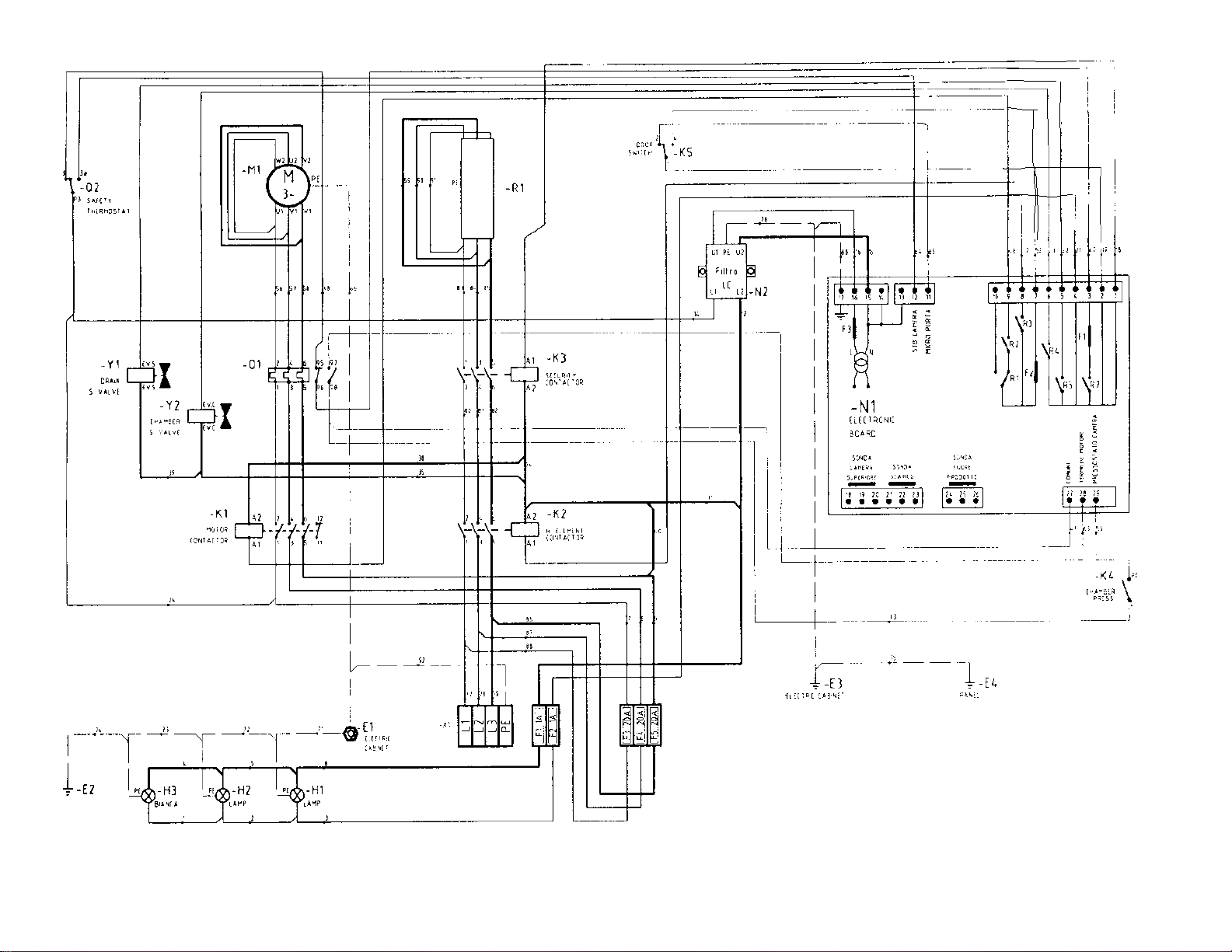
74
LCE-61 M
Page 75
75
LCE-61 M
Page 76
76
LCE-61 D
Page 77

77
LCE-61 D
Page 78

78
LCE-61 DP
Page 79

79
LCE-61 DP
Page 80

80
LCE-101 M
LCE-141 M
Page 81

81
LCE-101 M
LCE-141 M
Page 82
82
LCE-101 D
LCE-141 D
Page 83

83
LCE-101 D
LCE-141 D
Page 84

84
LCE-101 DP
LCE-141 DP
Page 85

85
LCE-101 DP
LCE-141 DP
Page 86

86
LCE-241 D
Page 87

87
LCE-241 D
Page 88

88
LCE-241 DP
Page 89

89
LCE-241 DP
Page 90

90
LCE-401 DP
Page 91

91
LCE-401 DP
Page 92

92
LCE-401 DP
Page 93

93
LCG-61 M
LCG-101 M
LCG-141 M
LCG-241 M
Page 94

94
LCG-61 M
LCG-101 M
LCG-141 M
LCG-241 M
Page 95
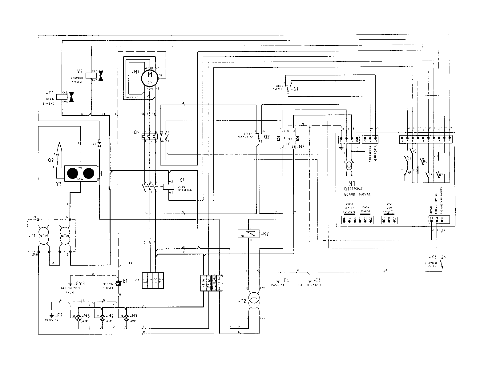
95
LCG-61 D
LCG-101 D
LCG-141 D
-
Page 96

96
LCG-61 D
LCG-101 D
LCG-141 D
LCG-241 D
Page 97

97
LCG-61 DP
LCG-101 DP
LCG-141 DP
LCG-241 DP
Page 98

98
LCG-61 DP
LCG-101 DP
LCG-141 DP
LCG-241 DP
Page 99

99
LCG-401 DP
Page 100

100
LCG-401 DP
 Loading...