

Page 1

Installation
Operation
Maintenance
136SB, 136SMB,
160SB, 160SMB Salamander
Lang Manufacturing 10 Sunnen Drive St. Louis, MO 63143
Part Number 2M-60807-01 Phone: 314-678-6315 Fax: 314-781-2714
Rev E www.langworld.com
October 4, 2012
Page 2

TABLE OF CONTENTS
INSTALLATION ..........................................................................................................................................1
RECEIVING
ELECTRICAL
VENTILATION
PLACEMENT
THE APPLIANCE ....................................................................................................................1
CONNECTION......................................................................................................................1
AND CLEARANCES..........................................................................................................1
ON RANGE............................................................................................................................2
NON - PREDRILLED RANGES..................................................................................................................2
PREDRILLED RANGES .............................................................................................................................2
OPERATION.................................................................................................................................................3
INITIAL
PREHEAT .......................................................................................................................................3
WIRING DIAGRAMS..................................................................................................................................4
208/240
440/480
VOLT ................................................................................................................................................4
VOLT ................................................................................................................................................5
EXPLODED VIEW & PARTS LIST ......................................................................................................6-7
Page 3
INSTALLATION
RECEIVING THE APPLIANCE
Upon receipt of the appliance, check for freight damage both visible and concealed. Visible damage
should be noted on the freight bill at the time of delivery and signed by the carrier's agent. Concealed loss
or damage means loss or damage which does not become apparent until the merchandise has been
unpacked. If concealed loss or damage is discovered, make a written request for inspection by the carrier's
agent within 15 days of delivery. All packing material should be kept for inspection. Do not return
damaged merchandise to Star Manufacturing International. File your claim with the carrier.
Uncrate the appliance as near its intended location as practical. The crating will help protect the unit from
the physical damage normally associated with moving it through hallways and doorways.
ELECTRICAL CONNECTION
The electrical connection must be made in accordance with local codes or in the absence of local codes
with NFPA No. 70 latest edition (in Canada use: CAS STD. C22.1).
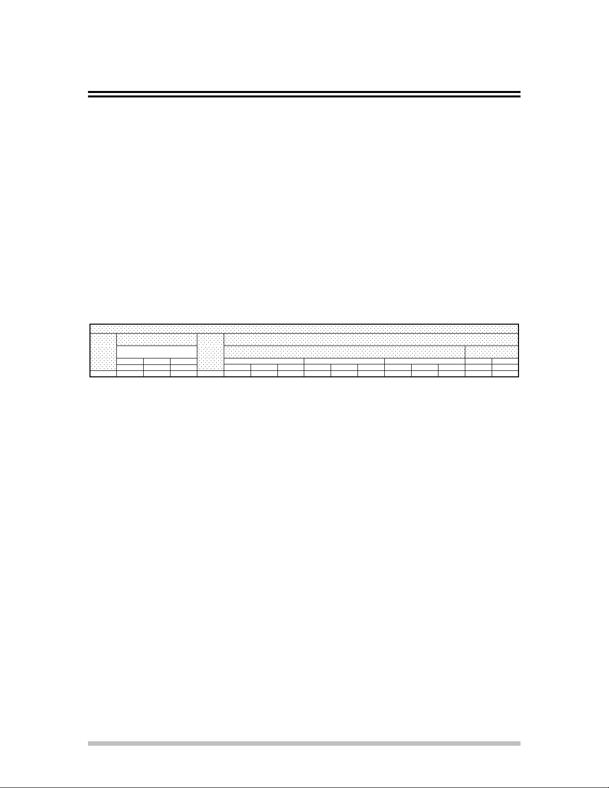
Supply wire size must be large enough to carry the amperage load for the number of appliances being
installed. Wire size information can be found on the data plate and on the chart below.
MODEL
NUMBER
36S-SH 6.0 6.0 0.0 6.0 28.8 28.8 0.0 25.0 25.0 0.0 12.5 12.5 0.0 28.8 25.0
TH REE PH A SE LOA DIN G NONINAL AM PS PER LINE
K. W. PER PHA SE
L1 - L2 L2 -L3 L3 - L1 208 VOLT 240 VOLT 480 VOLT 208 V. 240 V.
TOTAL
K.W.
L1 L2 L3 L1 L2 L3 L1 L2 L3 L1 L2
ELECT RI C A L D AT A
TH REE PHA SE SIN GLE PHA SE
VENTILATION AND CLEARANCES
Standard minimum clearance from combustible construction is as follows:
3 inches from sides
3 inches from back
Keep the appliance area free and clear of combustible material and do not obstruct the flow of combustion
or ventilation air.
The installation of any components such as a vent hood, grease extractors, and/or fire extinguisher systems,
must conform to the their applicable nationally recognized installation standards.
1
Page 4
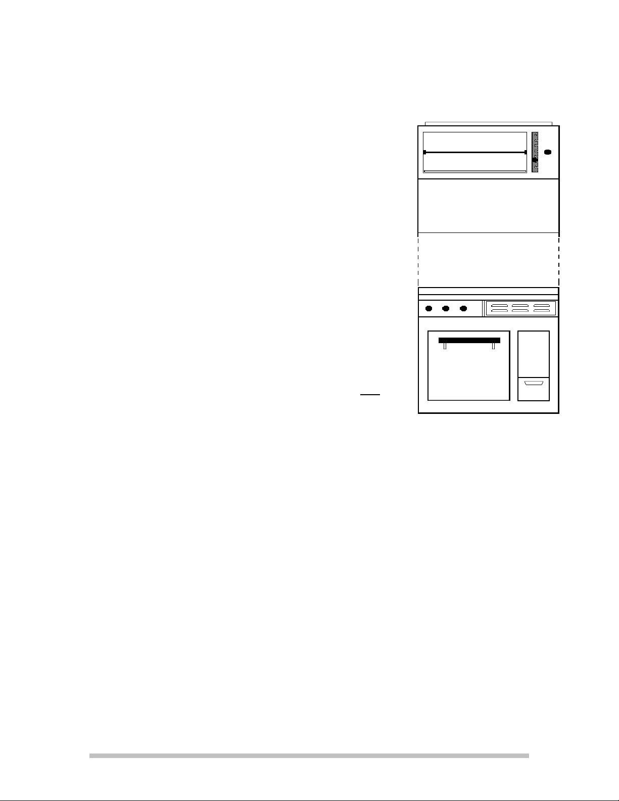
PLACEMENT ON RANGE
NON - PREDRILLED RANGES
If the range that the Salamander is to be installed on has been
predrilled by the factory, proceed to the next section - Predrilled
Ranges. If the range has not been predrilled, continue with this
section.
Place the Salamander on top of the range so that the back of the range
is flush with the back of the Salamander.
Mark the five holes in through the flange in the Salamander onto the
top of the range.
Mark the three holes through the side of the Salamander onto the side
of the range.
Remove the Salamander from the range.
Drill all eleven holes using a # 27 drill bit.
Tap the five holes in the top of the range with a 10-32 tap.
PREDRILLED RANGES
Place the Salamander on top of the range so that the holes in the
salamander line up with the holes in the range and the backs are flush.
Install five 10-32 x 3/8” Truss Head Machine Screws through the
holes in the back flange of the Salamander into the top of the range.
Install three 10-32 x 3/8” Truss Head MS SS Screws through each
side of the Salamander into the side of the range.
2
Page 5

OPERATION
INITIAL PREHEAT
Rotate the temperature dial until Hi is at the top.
Raise the broiler rack to the top most position and allow the rack to heat.
Lower the rack and place the product on it.
Raise the rack to the desired cooking position.
Set the temperature dial to the desired position.
3
Page 6

208/240 VOLT
WIRING DIAGRAMS
4
Page 7

440/480 VOLT
5
Page 8

21
1
15
14
17
16
20
19
18
12
2
4
5
6
7
3
9
8
13
SOME ITEMS ARE INCLUDED FOR
ILLUSTRATIVE PURPOSES AND IN
CERTAIN INSTANCES MAY NOT BE AVAILABLE
This drawing contains information confidential
to Lang Manufacturing
No reproduction or disclosure of it's
contents is permitted.
Model:
136SB - 160SB Salamander
11
10
SK2308 Rev. A 11/15/13
Page 9

PARTS LIST November 15, 2013, Rev E
Model No: 136SB, 136SBM, 160SB, 160SBM
SALAMANDER ELECTRIC BROILER
Key
Number
1 J9-SAL-130 1 BODY TOP C.T.M. ALL
2 J9-SAL-1424-1 1 BODY BACK C.T.M. ALL
3 2E-30500-09 1 TRM BLOCK 3 POLE SMALL 95 ALL
4 2C-20109-21 2 SCRW S/S 8-32X1 R/H M/S ALL
5 2E-31400-04 1 XFRMR 480/240VAC 100VA 136SB-480V, M-440V, M-480V
6 2E-30700-03 1 CONTC 3POLE 40A208-240VAC ALL
7 J9-SAL-141 1 BREAKER MOUNT ALL
8 J9-SAL-125-2 1 BODY SIDE RH C.T.M ALL
9 J9-SAL-179-3 1 HIGH SHELF ASSY SHORT 136SB
J9-SAL-179-4 1 HIGH SHELF ASSY SHORT 32S-HS
J9-SAL-179-5 1 HIGH SHELF ASSY SHORT 160SB
12 2E-30305-01 1 SWT INF 240V 15AMP ALL
13 J9-70701-04 1 KNOB ASSY INF CONTROL - BLACK
J9-70701-04-2 1 KNOB ASSY INF CONTROL - RED
14 2M-60301-43 1 DIE CAST PLT LANG SATIN ALL
15 J9-SAL-126-1 1 BODY FRONT C.T.M. ALL
16 J9-SAL-148-1 1 ELEMENT FRAME ASSY ALL
17 2N-11100-01 2 ELMNT BRL/SAL 208V 3KW 208V
2N-11100-02 2 ELMNT BRL/SAL 240V 3KW 240V
2N-11100-05 2 ELMNT BRLL/SAL 480V 2700W 440V / 480V
18 K9-SKSAL135-W1 1 GREASE PAN COMMERCIAL APPLICATIONS
K9-SKSAL135 1 GREASE PAN 36S-SH MARINE APPLICATIONS
19 J9-SAL-125-3 1 BODY SIDE RH C.T.M. ALL
20 J9-SAL-119 1 RACK DRIP PAN ALL
21 2B-50200-17 1 RACK SALAMANDER W/HANDLE ALL
Part
Number
Qty
Per
Description
IMPORTANT: WHEN ORDERING, SPECIFY VOLTAGE OR TYPE GAS DESIRED PAGE 1
INCLUDE MODEL AND SERIAL NUMBER OF 1
Some items are included for illustrative purposes only and in certain instances may not be available.
Page 10

Page 11

Page 12

STAR INTERNATIONAL HOLDINGS INC. COMPANY
Star - Holman - Lang - Wells - Bloomeld - Toastmaster
10 Sunnen Drive, St. Louis, MO 63143 U.S.A.
(314) 678-6303
www.star-mfg.com
 Loading...