

Land Rover Series I 1948 1951 User Manual
LAND
ROVER
OPERATION MANUAL

IMPORTANT
NOMENCLATURE
As this manual covers both Right and Left-hand Drive models, reference is
made throughout the text to the “left-hand” and “right-hand” sides of the
vehicle, rather than to the “near-side” and “off-side.” The “left-hand side”
is that to the left hand when viewed from the rear; similarly “left-hand
drive” models are those having the driving controls on the left-hand side,
again when the vehicle is viewed from the rear.
CAPACITIES
All capacities are quotes in Imperial and Metric measure; to ascertain the
U.S. equivalent, multiply the Imperial figure by 1.2.
GUARANTEE
In order to obtain the Certificate of Guarantee operative with your vehicle,
it is essential that you should, with the minimum of delay, either fill in and
post the guarantee form supplied or ask your supplier to do it for you.
Failure to do so may seriously jeopardise any claim you have on the
Company under the terms of the standard guarantee.
GEAR RATIOS
The Land-Rover is equipped with a transfer box giving a secondary series
of low gear ratios for heavy work. You are advised to consult “Gear
Changing Instructions” for full details of the operation of this transfer box.
LOCKING
To protect your Land-Rover against theft, always remove the ignition key
when parking. As an additional precaution the distributor rotor arm may
also be removed or the petrol tap on the sediment bowl turned “OFF.”
MAINTENANCE
In order to obtain maximum service and dependability from your LandRover, maintenance items listed in this manual should receive regular
attention. They are few in number and quite straightforward and will amply
repay the small amount of time which needs to be devoted to them.

OPERATION MANUAL
-- for the --
LAND ROVER
Regd. Trade Mark
1948-51 MODELS
Vehicles numbered:
R860001 to R863000
R8663001 onwards
R06100001 onwards
L860001 to L863000
L8663001 onwards
L06100001 onwards
R8670001 onwards
R06200001 onwards
L8670001 onwards
L06200001 onwards
R8680001 onwards
R06300001 onwards
L8680001 onwards
L06300001 onwards
(The prefix R is omitted from vehicles built to Home requirements, bearing serial numbers 06110348,
06200265 and 06300001 onwards).
) Standard vehicle
) Right-hand drive.
)
) Standard vehicle
) Left-hand drive.
)
) Station wagon
) Right-hand drive.
) Station wagon
) Left-hand drive.
) Welding outfit vehicle
) Right-hand drive.
) Welding outfit vehicle
) Left-hand drive.
THE ROVER CO. LTD.,
SOLIHULL, BIRMINGHAM, ENGLAND.
Telephone: SHEldon 2461.
Telegrams: Rover, Solihull.
A copy of this
operation manual is
sent out with each
SERVICE DEPT.
SOLIHULL, BIRMINGHAM, ENGLAND.
Telephone: SHEldon 2461.
Telegrams: Rovrepair, Solihull.
London Service Station
SEAGRAVE ROAD,
FULHAM, LONDON S.W.6., ENGLAND.
Telephone: FULham 1221.
Telegrams: Rovrepair, Wesphone, London.
vehicle. Additional
copies are obtainable
from either of the
addresses opposite.
PRICE – 5/-
ROVER PHONES:
Solihull (Head Office) - SHEldon 2461
Solihull Service Dept. - SHEldon 2461
London Service Station - FULham 1221
APRIL, 1950. Publication. No. TP/108/D

Attachments, towing 91, 96
A
Additives, oil 20
Additives, petrol 3
Adjustment, brake 53
Adjustment, clutch 39
Adjustment, distributor 68
Adjustment, fan belt 42
Adjustment, reverse stop 19
Adjustment, steering 53
Adjustment, tappet 38
Air cleaner 49
Anti-freezing mixture 43
Axles 6, 29
B
Brake adjustment 53
Brakes 6, 53
Brakes, bleeding 55
Battery 64
Box, control 67
Bulbs 71
C
Cable, high tension 70
Capacities (special note)
Inside front cover
Capacities 7
Capacity, engine oil 5, 26
Capacity, petrol 5, 45
Capacity, water 5, 42
Capstan winch 104
Carburettor 50
Carrier, spare wheel 95
Chaff guard 105
Chassis lubrication 30
Cleaner, air 49
Clutch 6, 39
Clutch adjustment 39
Clutch lubrication 27
Coil 68
Controls 10-14
Control box 67
Control, ignition 36
Control, mixture 11, 15
Coolant, draining 42
Cooler, oil 106
Cooling system 5, 40
D
Dampers, hydraulic 55
Decarbonising 35
Description 7
Dimensions, vehicle 7
Dimensions, engine 5
Dipper switch, lamp 10
Distributor adjustment 68
Distributor lubrication 27
Distributors, Rover
INDEX
(British Isles) 111-120
Distributors, Rover
(Overseas) 121-128
Doors 84
Draining Coolant 42
Dynamo 27, 66
E
Electrical equipment 64-76
Engine governor 105
Engine timing 36
Engine lubrication 21
Engine dimensions 5
F
Fan belt adjustment 42
Fault location 77-83
Filter, oil, external 26, 27
Foot pedals 10, 30
Foot pedal pads 95
Freewheel 6
Front axle lubrication 29
Front hub lubrication 29
Front wheel drive lock 13
Frost precautions 43
Fuel system 5, 44
Fuse 4, 67
G
Gauge, petrol level 13
Gearbox 6
Gearbox lubrication 28
Gear changing 16-19
Gear ratios 6
Governor, engine 105
Guarantee 2
H
Hand-rail, passenger 9
Heater, vehicle 93
Hoods 85-90
Horn 74
Horn button 10
Hub, front, lubrication 29
Hydraulic dampers 55
I
Ignition 5, 68-71
Ignition control 36
Ignition switch 12
Ignition warning light 12
In case of trouble 77-83
Instruments 10
Instrument panel light switch 12
Introduction 1
L
Lamps 71 –74
Lamp dipper switch 10
Lamp focussing 72
Lamp setting 72-73
Lamp switch 12
Level gauge, petrol 13

Location of faults 77-83
Location of Solihull factory 129
Lock, front wheel drive 13
Locking Inside front cover
Lubricants, recommended 32-33
Lubrication 20-30
Lubrication, axles 29
Lubrication, chassis 30
Lubrication, clutch 27
Lubrication, distributor 27
Lubrication, engine 21
Lubrication, front hub 29
Lubrication, gearbox 28
Lubrication, propeller shaft 28
Lubrication, steering box 30
Lubrication, suspension 30
Lubrication, transfer box 28
Lubrication, upper cylinder 3
M
Maintenance points 31-35
Map of Solihull factory 129
Mixture, anti-freezing 43
Mixture control 11, 15
Nomenclature Inside front cover
Numbers, vehicle 4
O
Oil additives 20
Oil capacity, engine 5, 26
Oil cooler 106
Oil filter, external 26, 27
Oil pressure 12, 26
Oil pressure warning light 12, 26, 76
P
Pad, foot pedal 95
Pedals, foot 10, 30
Petrol system 5, 44
Petrol additives 3
Petrol capacity 5, 45
Petrol level gauge 13
Petrol pump 46
Plugs, sparking 39
Power take-off 96-104
Precautions, frost 43
Pressure, oil 12, 26
Pressures, tyre 57
Propeller shaft lubrication 28
Pulley, rear power take-off 103
Pump, fuel 46
R
Ratios, gear 6
Rear axle lubrication 29
Recommended lubricants 32-33
Rover distributors
(British Isles) 111-120
Rover dealers (Overseas) 121-128
Running-in period 2
S
Seats 84
Seats, rear 94
Sediment bowl 45
Setting lamps 72-73
Sidescreens 84
Spare wheel 9, 57
Sparking plugs 39
Special notes 2
Specification 5
Springs, road 55
Starter 12, 15, 68
Starter switch 12, 15
Starting 15
Station wagon 109-110
Steering 7, 52
Steering box lubrication 30
Suspension 6, 55
Suspension lubrication 30
Switch, dipper lamp 10
Switch, ignition 12
Switch, instrument panel light 12
Switch, lamp 12
Switch, starter 12, 15
Switch, windscreen wiper 13
T
Towing attachments 91, 96
Tappet adjustment 38
Technical Service 130
Timing 36
Tools 9-10
Trafficators 93
Trailer, Brockhouse 107
Transfer box 6, 13, 18
Transfer box lubrication 28
Transmission 6
Trouble finding 77-83
Tyre pressures 57
Tyres 56-63
U
Upper cylinder lubrication 3
V
Vehicle heater 93
Vehicle serial numbers 4
Ventilator, windscreen 95
W
Warning light, ignition 12, 75
Warning light, mixture
control 11, 15, 16, 75
Warning light, oil pressure 12, 26, 76
Water system 40
Water capacity 5, 42
Weights 7
Welding plant vehicle 108
Wheels 56-63
Wheel balancing 63
Wheel, spare 9, 57
Winch, capstan 104
Windscreen 9
Windscreen ventilator 95
Windscreen wiper 13, 74
Wiring diagram Inside rear cover
INTRODUCTION
“Occasions when the owner finds himself in
In the design of the Land-Rover every effort has been made to simplify as
far as possible the amount of attention which the owner must devote to
upkeep. For this manual we have endeavoured, by the use of illustrations, to
make the instructions for items of routine maintenance as simple and as
clear as possible. At the same time we realise that there may be occasions
when the owner finds himself in some difficulty; such cases are dealt with
by our Service Department and the
information given on Page 130 will
help you.
Operating instructions for the
standard vehicle are given on Pages
1-92, while details of extra
equipment are set out on Pages 93106; reference to the Land-Rover
Station Wagon is made on Page
109 and to the Welding Plant
version on Page 108.
some difficulty”
In the event of spare parts being required, they may be obtained through the,
nearest Rover agent or in cases where difficulty ' experienced, directly from
us. A list of Rover Agents (both Home and Overseas) is given at the back of
this book.
It will be realised that from time to time, alterations in design and in the
make of various accessories occur and this operation manual, while being
kept up-to-date as far as possible, is not to be taken as a standard
specification of the Land-Rover.
We reserve the right, to alter the specification at any time and without
incurring any obligation to incorporate such alteration in vehicles already
delivered.
The purchaser is earnestly requested to fill in the Guarantee form supplied
with the vehicle, upon receipt of which we will place his name on our list of
owners and return the completed Guarantee form.
'I'HE ROVER Co. Ltd.,
SOLIHULL,
BIRMINGHAM,
ENGLAND.
APRIL 1950 1
SPECIAL NOTES
“Avoid steam which may be blown out
GUARANTEE.
In order to obtain the Certificate of Guarantee operative with your vehicle,
it is essential that you should, with the minimum of delay, either fill in and
post the guarantee form supplied or ask your supplier to do it for you.
Failure to do so may seriously jeopardise any claim you may have on the
Company under the terms of the standard guarantee.
COOLING SYSTEM.
The cooling system is pressurised and great care must be taken when
removing the radiator filler cap,
especially when the engine is hot, to
avoid steam which may be blown
out with considerable force.
I'HE RUNNING-IN PERIOD.
The years of good service expected
from your vehicle will depend to a
large extent upon the treatment it
receives in the early stages. It is
most important that your LandRover be properly “run-in”, that is,
it should, be given an initial period
with considerable force”
of service during which it must be
driven carefully at moderate speeds
so that no component is subjected to extreme loads.
We recommend a running-in period of 500 miles (750 Km.) during which
35-40 m.p.h. (55-65 k.p.h.) in high transfer ratio should not be exceeded,
but even after that the vehicle should not be driven at prolonged high speeds
until it has done 1, 000 miles (1,500 Km.); good use should be made of the
gearbox and a change-down to a lower gear made if the engine is subjected
to hard pulling in a high gear. Never race the engine when cold at any time
during the life of the vehicle.
The instructions pasted on the windscreen are only general and to get the
most lasting benefit the owner will not only obey these, but also see that he
does not, on prolonged stretches, do even 40 m.p.h. (65 k.p.h.) if it means
using full throttle during the first 500 miles (750 Km.).
APRIL 1950 2

It may well be that you desire to use the Land-Rover for other purposes
besides road-work, even when it is new; it may he required for driving,
stationary equipment or for cross-country work necessitating low transfer
ratio. In the latter case 15 m.p.h. (25 k.p.h.) should not be exceeded in top
gear whilst running-in, with correspondingly lower speeds in the
intermediate gears. For stationary work an engine speed of 2,000 r.p.m.
should be regarded as the maximum during the first five hours and this
figure can be raised to 3,000 r.p.m. for the next ten hours. As an engine
revolution indicator is not fitted to the Land-Rover, reference should be
made to the table below to ascertain the road-speed corresponding to these
figures and the hand-throttle marked to give these settings during a trial run
on the road.
ENGINE R.P.M.
2,000 30 m.p.h. (50 k.p.h.). 12 m.p.h. (20 k.p.h.).
3,000 46 m.p.h. (70 k.p.h.). 17 m.p.h. (27 k.p.h.).
Top gear (high transfer). Top gear (low transfer).
ROAD SPEED
Your dealer will carry out a complete check-over on the vehicle after 750
miles (1.000 Km.) if used exclusively for road-work or after 30 hours when
mainly used in low transfer ratio for farming purposes. The inspection will
conform to the Free Service Card supplied with the vehicle and includes
changing the oil in the engine, gearbox, transfer box and axles. A second
check-over will be given after 1,500 miles (2.500 Km.) or 60 hours.
UPPER CYLINDER LUBRICATION.
During the early life of the vehicle we recommend the use of an upper
cylinder lubricant. It should be used in the proportion of one fluid ounce to
four gallons of petrol (three centilitres to twenty litres) and added to the
tank before filling with petrol to ensure thorough mixing.
We have tested and exclusively recommend the following lubricants:-
Wakefield's Castrollo.
Mobil Upperlube.
Shell Donax U.
or Energol U.C.L.
The addition of upper cylinder lubricant is not considered so essential after
the engine has been "run-in," but it can be continued without any
detrimental effect.
APRIL 1950 3

FUSE.
“First examine the fuse”
“The registration number . . . is of no
The single fuse fitted in the electrical
system protects the horn, windscreen
wiper, petrol tank gauge unit and rear stop
lights. It is situated under a bakelite cover
on the engine side of the scuttle panel on
the right-hand side a spare fuse is carried
under the same cover. In the event of a
failure occurring on any of the
components detailed, first examine the
fuse to make sure that it has not "blown."
VEHICLE SERIAL NUMBERS
The vehicle serial number will be
found on a plate fixed to the scuttle
panel. Owners are requested to quote
this number in all correspondence;
the registration number of the vehicle
is of no use whatever to us.
Certain units also carry serial
numbers as detailed below, but they
should not be quoted unless specially
asked for, as we can identify them
from our records, providing the
vehicle number is given.
use whatever to us.”
Chassis number is stamped on the top
of the left-hand front engine bearer bracket.
Engine number is stamped at the top front of the cylinder block on the lefthand side, adjacent to the water PUMP.
Gearbox number is stamped on the right-hand side of the casing at the rear.
Rear axle number is stamped on to of the axle casing on the left-hand side.
Front axle number is stamped on top of the axle casing on the left-hand
side.
APRIL 1950 4

GENERAL DATA AND DIMENSIONS
“Waterproof covers on
ENGINE. Four cylinders cast en bloc with detachable cylinder head.
Flexibly mounted on rubber at four points. Three crankshaft bearings; four
cam- shaft bearings. Vibration damper on crankshaft integral with fan
driving pulley. Overhead inlet valves operated by followers and push rods;
side exhaust valves by direct rockers from camshaft; camshaft is driven by
duplex chain automatically adjusted by hydraulic tensioner. Lubrication is
full pressure from gear-type oil pump to all bearings and valve gear.
External A.C. by-pass pressure filter and a gauze pump intake filter in the
sump.
Bore 69.5 mm. (2.736 in.).
Stroke 105 mm. (4.133 in.).
Cylinder capacity 1,595 c.c. (97.34 cu. in.)
Compression ratio 6.8 - 1
B.H.P. 50-55 at 4,000 R.P.M.
R.A.C. Rating 11.98 H.P.
Max. torque 80 lbs. / ft.(11 mKg.) at 2,000 R.P.M.
Firing order 1, 3, 4, 2.
Sump capacity 10 pints (5,5 litres).
COOLING. Impellor type water pump and fan driven from crankshaft.
Temperature controlled by thermostat. Pressurised system to decrease loss
of coolant under hard working conditions. Total capacity 17 pints (9,75
litres).
IGNITION SYSTEM. Battery and coil.
Distributor has both centrifugal and vacuum
advance and retard. Waterproof covers on
sparking plugs.
FUEL SYSTEM. Petrol from tank under
seat-box on right-hand side is delivered to
the Solex 32 P.B.I.2 down-draught
carburettor by electric S.U. pump. AC.
sediment filter between tank and pump. AC.
oil-bath air cleaner. Fuel capacity 10
Imperial gallons (45 litres).
APRIL 1950 5
Sparking Plugs”

CLUTCH. Single dry plate 9 in. (230 mm.) diameter.
MAIN GEARBOX. Single helical constant-mesh gears, with synchromesh
on top and third speeds.
TRANSFFR BOX. Two-speed reduction gears on main gearbox output.
Incorporates free-wheel unit in front axle drive.
TRANSMISSION. Hardy-Spicer open propellor shafts to front and rear
axles.
REAR AXLE. Spiral bevel pattern. Semi-floating axle shafts. Ratio 4.7-1.
(4.88-1 for axle numbers up to 861371).
FRONT AXLE. Spiral bevel differential. Drive transmitted through
enclosed constant velocity universal joints. Ratio 4.7-1. (4.88-1 for axle
numbers up to 861371).
OVERALL GEAR RATIOS. The table below gives the overall gear ratios,
i.e., total reduction obtained through main gearbox, transfer box and axles.
(Axles numbered 861372 onwards).
MAIN GEARBOX
High ratio. Low ratio.
TRANSFER BOX
Top gear 5.396 13.578
Third 7.430 18.697
Second 11.023 27.738
First 16.165 40.676
Reverse 13.743 84.581
SUSPENSION. Semi-elliptic leaf springs with rubber bushes controlled by
telescopic hydraulic dampers.
BRAKES. Girling hydraulic brakes on all wheels. Handbrake applies
Girling mechanical brake on transfer box output shaft for parking purposes
only.
WHEELS. 16" divided or 16" well-base pattern.
TYRES. 6.00-16 or 7.00-16.
APRIL 1950 6

ELECTRICAL SYSTEM. Lucas 12-volt starting and lighting set. Battery
51 A.H. mounted at right of engine well clear ground.
STEERING. Burman worm and nut pattern.
VEHICLE DIMENSIONS.
Overall length 132 in. (3,35 m.).
Overall width 61 in. (1,55 m.).
Overall height - hood up 70½ in. (1,79 m.).
- hood down, screen up 65½ in. (1,66 m.).
- hood down, screen down 53 in. (1,35 m).
Wheelbase 80 in. (2,03 m.).
Track 50 in. (1,27 m.).
Ground clearance 8½ in. (216 mm.).
Turning circle (6.00-16 tyres) 35 ft. (10,5 M.).
(7.00-16 tyres) 40 ft. (12,2 m.).
Weight - running (with water, oil and fuel) 2,604 lb. (1.136 Kg.).
- maximum approved gross loaded 4,032 lb. (1.829 Kg.).
Maximum approved pay load (in addition to passengers) 1,000 lb. (450 Kg.).
Maximum draw bar pull
(according to surface conditions). 1,200-2,000 lb. (550 to 900 Kg.).
Internal body dimensions - length 37½ in. (952 mm.).
- width 56½ in. (1,43 m.).
- depth 14½ in. (368 mm.)
CAPACITIES.
Engine sump 10 pints (5,5 litres).
Air cleaner 2 pints (1,0 litre).
Main gearbox 4 pints (2,25 litres) .
Transfer box 6 pints (3,5 litres).
Rear axle 3 pints (1,75 litre).
Front axle 3 pints (1,75'Iitre).
Tracta joints (each) 1 pint (0,5 litre).
Fuel tank 10 Imp. gallons (45 litres)
Cooling system 17 pints (9,15 litres).
DESCRIPTION
The main characteristics of the Land-Rover are brought out in Figs. 1 and 2;
there are, however, a few small points which may not be too clear from the
illustrations and which require explanation to ensure your obtaining the
maximum utility from the vehicle.
The front bumper (A) is retained by bolts and hence readily detachable to
facilitate straightening should it become damaged in service.
APRIL 1950 7
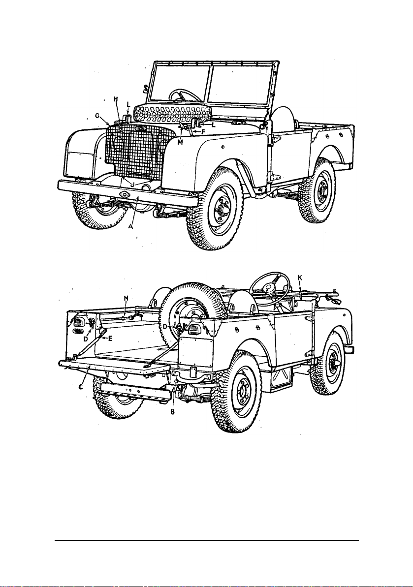
Fig. 1. (Three-quarter front view).
Fig. 2. (Three-quarter rear view).
A-Detachable front bumper. H-Grille clamp.
B-3-pin socket. J-Grille bracket.
C-Tailboard. K-Windscreen clamp.
D-Tailboard key. L-Windscreen support.
E-Tailboard chain. M-Windscreen fastener.
F-Bonnet fastener. N-Jack handle clips.
G-Radiator grille panel.
APRIL 1950 8

When towing a trailer, connection for the trailer tail and stop lamps are provided
by the three-pin-socket (B) fitted in the right-hand side of the rear chassis crossmember. (See "Towing Attachments").
The tailboard (C) can be lowered to its horizontal position by withdrawing the
keys (D). To remove the tailboard from the vehicle, unhook the two chains (E),
lower it as far as possible and slide off the hinges to the left.
Two spring fasteners (F) secure the bonnet top panel in the closed position; it
can be held in the open position by means of the stay rod clipped under the
panel on the left-hand side. The panel can be removed from the vehicle by
raising it to a vertical position and sliding off its hinges to the left.
The headlamps and horn are protected by the radiator grille (G) which is readily
removed by detaching the two bolts and clamps (H), and lifting out from the
brackets (J).
The hand-rail mounted on the dash is fitted for the convenience of front seat
passengers when traversing rough ground.
Provision is made for folding the windscreen down on to the bonnet (Fig. 2). To
do this, release the two clamps (K) from the dash panel and lower the
windscreen on to the supports (L); secure in this position by means of the spring
fasteners (M). To prevent rattles when not in use, these fasteners are normally
clipped to the bonnet panel (Fig. 1).
The spare wheel is stowed in the depression in the body floor (Fig. 2) and
retained by means of a clamp and wing-nut. When it is desired to utilise the
entire body space for load-carrying the spare wheel can be carried in the
alternative position on the bonnet top (Fig. 1). The mounting plate for this
purpose is supplied as an extra component. With the spare wheel carried in this
way, it is not possible to fold the windscreen into the horizontal position.
The hinged flap in the gearbox cover just to the rear of the main gear change
lever affords access to the gearbox oil filler and dip-stick, whilst that in the
centre of the seat-box covers the power take-off engagement lever. The locker
lid on the right-hand side of the seat-box, encloses the petrol tank and filler (see
Fuel System) and the brake fluid reservoir (see Brake System).
TOOLS. The small tools are carried in the locker under the seat-box on the lefthand side. Clips for the starting handle are fitted on the rear of the seat back-rest
panel and those (N) for the jack handle on the inside of the left-hand side panel
(Fig. 2). When certain items of special equipment are installed, the jack handle
is stowed in clips along the dash above the instrument panel.
APRIL 1950 9

The standard tool-kit supplied with each vehicle comprises:
Wheel brace *Adjustable spanner
Lifting jack *Distributor screwdriver and feeler
gauge
Tyre pump *Spanner (3/8 in.)
Oil gun *Sparking plug spanner
*Pliers *Box spanner
*Screwdriver *Tommy bar
*Open-ended spanner (3/16 in.
*Tyre pressure gauge
x 1/4 in.)
*Open-ended spanner (5/16 in.
x 7/16 in.)
Items marked * are contained in a leather tool roll.
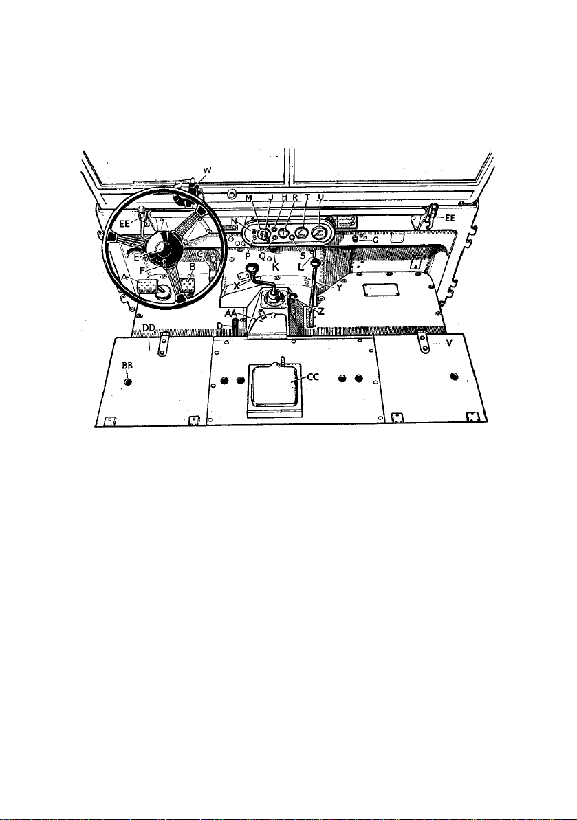
CONTROLS AND INSTRUMENTS
The principal controls and instruments are illustrated on the opposite page,
where it will be seen that the layout is very similar to that on a normal car,
with the addition of gearbox transfer and front wheel drive lock controls.
Except for the positions of the steering column, foot-pedals and handbrake
lever, the layout is the same for both left-hand and right-hand drive
vehicles.
FOOT PEDALS. The three foot-pedals are normal in position and
operation, i.e., the left-hand pedal controls the clutch, the centre pedal the
foot brake and the right-hand pedal the accelerator.
HAND-BRAKE. The hand-brake lever protrudes through the front of the
seat-box, to the driver's left hand on a R.H.D. vehicle, and to his right hand
on a L.H.D. vehicle. In the "off" position it is parallel with the floor; to
apply the brake pull the lever upwards; to release, pull up slightly, depress
the small knob in the end of the lever and push downwards as far as
possible.
STEERING COLUMN. This is positioned either to the right or left-hand
side; in both cases, the horn push-button is fitted in the centre of the steering
wheel, with the headlamp dipper switch on the wheel boss.
Operation of this switch replaces the primary filaments in both lamps by
secondary "out-of-focus" filaments.
APRIL 1950 10
MIXTURE CONTROL. The mixture control is situated on the dash to the
right, below the instrument panel. It is marked “COLD START”
and its operation and also the action of the mixture control warning light are
fully described on Page 15. This light is amber in colour and is located in
the centre of the instrument panel at the top.
Fig. 3. Controls and instruments.
A-Clutch pedal. R-Ammeter.
B-Brake pedal. S-Oil pressure warning light.
C-Accelerator pedal. T-Petrol level gauge.
D-Hand-brake. U-Speedometer.
E-Horn button. V-Access to petrol filler and brake fluid reservoir.
F-Headlamp dipper switch. W-Windscreen wiper.
G-Mixture control. X-Main gear-change lever.
H-Mixture control warning light. Y-Transfer box change lever.
J-Ignition switch. Z-Front wheel drive lock.
K-Starter switch. AA-Access cover for gear-box filler.
L-Slow-running control. BB-Location hole for seat.
M-Lamp switch. CC-Access cover for power take-off control.
N-Instrument panel light switch. DD-Tool-box.
P-Lead lamp socket. EE-Windscreen clamp.
Q-Charging warning light.
APRIL 1950 11

IGNITION SWITCH. This takes the form of a barrel lock controlled by a
small yale-type key, situated in the centre of the main lamp switch on the
instrument panel. When the ignition is switched off, the key can be
withdrawn.
STARTER SWITCH. The switch operating the starter motor is located on
the dash to the left below the instrument panel. To operate, press the knob
and release as soon as the engine fires.
SLOW-RUNNING CONTROL. Situated to the right of the starter switch is
a slow-running control; by pulling out this control, the engine idling speed
may be increased when desired for stationary work. Prior to road Usage, the
idling speed should always be returned to normal to facilitate gear changing.
LAMP SWITCH. A rotary type lamp switch is located on the instrument
panel; turn the handle until the pointer registers with the required position:"OFF," "S" (side and tail) or "H" (side, tail and, headlamps).
INSTRUMENT PANEL LIGHT SWITCH. The " push-pull " switch
controlling the panel lights is situated at the top left-hand corner of the
instrument panel. It is only operative when the ignition is “ON.”
LEAD LAMP SOCKET. Below the panel light switch are a pair of sockets
which can be used either for a lead lamp or a trickle battery charger. The
electrical system being of the "positive earth" variety, the red socket is
earthed.
CHARGING WARNING LIGHT. The red warning light at the bottom
centre of the instrument panel glows when the dynamo fails to charge, or
when the charging rate is lower than the voltage of the battery; in the latter
case it will go out when the engine speed is increased above normal idling.
AMMETER. The ammeter is located to the right of the charging warning
light.
OIL PRESSURE WARNING LIGHT. The oil pressure warning light to the
right of the ammeter glows when, for any reason, the engine oil pressure
falls below a safe figure. Should this light, appear during normal operation,
stop the vehicle at once and ascertain the cause - usually low oil level in the
sump. Never operate the vehicle with low oil pressure as serious damage to
the engine will result.
APRIL 1950 12

PETROL LEVEL GAUGE. The petrol level gauge will always show ZERO
when the ignition is switched off. It must be stressed that, while the gauge
will always give a reliable indication of the petrol level, it is not a precision
instrument and therefore cannot be employed to derive accurate petrol
consumption figures. Such tests should always be made with an auxiliary
tank of known size.
PETROL FILLER. The petrol filler cap is located beneath the locker lid on
the right-hand side of the seat-box; when the cap is removed, a telescopic
tube may be drawn out of the tank neck to facilitate filling. The tank
capacity is 10 Imperial gallons (45 litres).
WINDSCREEN WIPER. A windscreen wiper is fitted on the driver's side
only. To set the wiper in operation, pull out the horizontal lever a short way
and turn it to clear the vertical lever; turn the latter to the right. To park the
blade, reverse the operations.
MAIN GEARBOX CONTROL. The main gear-change lever is situated in
the centre of the gearbox cover; it has five positions - four forward speeds
and reverse. For gear-changing instructions see Pages 16-19.
TRANSFER BOX CONTROL. The transfer box which gives two ratios in
the output from the main gearbox (i.e., making eight forward and two
reverse speeds in all) is controlled by the lever to the right of the gearbox
cover. Push the lever right forward for high ratio and pull right back for low
ratio. The lever should be left in the neutral (central) position when using
the power take-off pulley for stationary work. On no account must low ratio
be selected unless the vehicle is stationary with the clutch depressed. Full
instructions for the use of the transfer box are given on Pages 18-19.
FRONT WHEEL DRIVE LOCK. Four-wheel drive is fitted as standard on
the Land-Rover. The drive to the front wheels incorporates an over-run
freewheel unit which eliminates any undue tyre wear on the front wheels or
excessive strain on the transmission when travelling on hard surfaces.
The inclusion of this freewheel means that all four wheels are driving only
when the engine is pulling and the vehicle is travelling in a forward
direction. When reversing or the engine is coasting with the vehicle
travelling forward, the drive is to the rear wheels only. There may be
occasions when four-wheel traction is necessary in reverse while operating
on soft surfaces or in a forward gear when descending a steep, muddy
gradient and provision has therefore been made to "lock" the freewheel unit
and so obtain four-wheel drive under such conditions.
APRIL 1950 13

The control for this operation (known as the "FRONT WHEFL DRIVE
LOCK") takes the form of a knob on the gearbox cover. It is so arranged
that the freewheel can only be locked by pressing this knob downwards,
when the transfer lever is in 'LOW ratio; the unit is automatically returned
to its normal free condition when the transfer lever is returned to the HIGH
position on resuming hard surface travelling.
The control must only he operated when the vehicle is stationary.
Note:- On approximately the first 14,000 vehicles, the control takes the
form of a key ring in the right-hand floor board, instead of the knob. Its
operation is identical with the later version, except that the ring must be
pulled upward about ¼ in. (7 mm.) to lock the freewheel unit.
APRIL 1950 14

STARTING PROCEDURE
Before attempting to start the engine, read the special notes which follow.
SPECIAL NOTE MIXTURE CONTROL. The mixture control has three
positions and there is no graduation between them. The mixture is
NORMAL when the control is right in as far as it will go. The WARMINGUP position can be found by pulling out the control until a light click is felt;
it is a little more than half-way out. The RICH or STARTING position is
with the control right out. On no account leave the control in any position
between those indicated above and do not forget to push the control right in
as soon as the engine temperature will permit. The appearance of the
AMBER WARNING LIGHT on the instrument panel will indicate that the
control has been left out inadvertently and must be pushed right in.
SPECIAL NOTE ACCELERATOR. The carburettor is fitted with an
accelerator pump, the action of which is such that if the throttle is fully
depressed, an extra rich mixture is provided to assist acceleration. As this is
not wanted when starting the engine, except under abnormal starting
conditions, DO NOT TOUCH THE ACCELERATOR PEDAL at all if the
engine is COLD. It may assist starting a hot engine if the throttle is opened
half-way and released as soon as the engine fires. Never pump the
accelerator pedal under any circumstances.
Having read the special notes above, ensure that:-
1. The MAIN GEAR-CHANGE LEVER is in the NEUTRAL position,
that is to say, in the midway position between the gears. When in this
position it can be moved sideways the full width of the "gate."
2. The TRANSFER LEVER is in the HIGH gear position i.e., right
forward.
Then set the MIXTURE CONTROL to suit:(a) right out if the engine is cold.
(b) in the mid-way position if the engine is warm.
(c) right in if the engine is hot.
Finally, switch on the IGNITION; press the STARTER BUTTON and the
engine should start up after a turn or two.
APRIL 1950 15

FALSE START. If the engine makes
“Should the engine fail to start . . .
a false start when operating the
starter button, i.e., fires and does not
continue to run, but throws the starter
pinion out of mesh, it is imperative
to wait until the pinion and flywheel
comes to rest before again pressing
the starter button; failure to observe
this precaution may jam and bend the
shaft of the starter motor. Should the
ascertain why.”
engine fail to start after two or three
attempts, ascertain why it will not start, or the battery will run down
needlessly.
WHEN THE ENGINE STARTS. Except under conditions of extreme Cold,
the mixture control should be pushed in from the RICH (right out) position
to the WARM-UP (mid-way) position within a few seconds of the engine
starting. This period may have to be extended if conditions are severe, but
should never exceed a minute or so.
Do not race the engine, but it is permissible to drive away at moderate
speed, immediately after starting. This, or opening to about quarter-throttle
by means of the slow running control if the vehicle is to be used stationary,
is definitely advised, as lubrication of the cylinder walls by oil-fling is
thereby stimulated as the engine warms up. Continue with the mixture
control in the mid- way position until the engine temperature has risen
sufficiently to allow the knob to be pushed right in to the NORMAL
position. The appearance of the AMBER WARNING LIGHT on the
instrument panel will indicate that the control has been left out inadvertently
and must be pushed right in at once.
SPECIAL NOTE WARNING LIGHT. Like all mechanical devices the
mixture control warning system is not completely fool-proof and the
responsibility for pushing the mixture control to the normal position rests
with the driver, especially as the warning light may never appear owing to
bulb failure. As a guide the engine should always run satisfactorily in the
normal position within 1 mile (1 Km.) from starting away.
The positions of the main gear change lever are marked on the lever knob. It
should be noted that the only reverse stop is a spring in the selector
mechanism which tends to hold the lever away from the reverse selector
slot.
APRIL 1950 16
GEAR CHANGING INSTRUCTIONS

Throughout the instructions which follow, approximate speeds are quoted at
which the various gear-changes should be made. These are given only to
serve as a guide to owners who are unaccustomed to the Land-Rover;
naturally they can be modified considerably as experience is gained under
various operating conditions. At all times care should be taken against
"racing" the engine and a "change-up" should be made well before the
engine revolutions reach their peak.
Do not drive with the foot resting on the clutch pedal. To 'ride" the clutch in
this way causes excessive wear of the withdrawal mechanism.
GEAR CHANGING. (Transfer box in high gear).
CHANGING UP. Assuming, that the engine is running, to start the vehicle
from rest proceed as follows:-
Depress the clutch pedal fully, pause for a moment to allow the clutch shaft
to stop spinning and then move the gear lever into the first gear position.
Release the handbrake by pulling the lever slightly upwards, release the
catch by pressing down the knob on top of the brake lever and let the lever
go downwards. Accelerate slightly and at the same time allow the clutch
pedal to come back until you feel the clutch just gripping. Further gentle
pressure of the accelerator will be necessary as the clutch takes up the drive
and by this time the clutch should be right in.
After having set the vehicle in motion continue in first gear, speeding up the
engine until 5-8 m.p.h. (8-15 k.p.h.) is attained, when second gear should be
selected as follows:(i) Depress the clutch pedal fully, at the same time taking the foot off
the accelerator pedal.
(ii) Move the gear lever into neutral.
(iii) Pause (count " one, two ").
(iv) Move the gear lever gently into the second 'gear position.
(v) Release the clutch pedal, at the same time pressing the accelerator
pedal gently down.
To change up from second to third speed, continue in second gear until
about 15 m.p.h. (25 k.p.h.) is reached. Then depress the clutch pedal fully,
at the same time releasing the accelerator, and move the gear lever towards
third gear position. It will be found to dwell for a moment, due to the
engagement of the synchromesh cones; do not force the lever, but maintain
a light pressure on it, and at the correct moment it will slip into third gear,
ensuring a silent and easy change. Release the clutch pedal and continue
with the acceleration.
APRIL 1950 17

Repeat these operations for changing from third to top gear speed of
approximately 20-25 m.p.h. (35-40 k.p.h.).
CHANGING DOWN. To change down from top to third gear, depress the
clutch pedal and ease the foot off the accelerator; move the gear lever gently
but firmly towards third gear position, when the same "dwell" will be felt
before third gear engages. Accelerate and let in the clutch.
When changing from third to second and from second to first gear, the
double de-clutch method should be used, as the synchromesh mechanism
does not operate on these two gears. Proceed as follows:-
(i) Depress the clutch pedal and move the gear lever into neutral.
(ii) Let in the clutch and accelerate until the engine speed is judged to
correspond with the vehicle speed in the gear to be selected.
(iii) Again de-clutch and move the gear lever into the required position.
(iv) Let in the clutch.
Do not snatch or force the gear lever; if the engine speed has been judged
correctly, the gear will engage quietly and smoothly.
REVERSE. To reverse the vehicle from a standstill, depress the clutch
pedal fully, engage reverse gear position and slowly release the clutch
pedal, at the same time gently speeding up the engine by means of the
accelerator pedal.
STARTING THE VEHICLE ON AN UPGRADE. When starting on an
upgrade is necessary, hold the vehicle with the handbrake and select first
gear; depress the accelerator in the normal way whilst simultaneously
releasing the handbrake and letting in the clutch.
USE OF THE TRANSFER BOX. The transfer box gives two ratios in the
output from the main gearbox, termed "high" and "low," thus giving a total
of eight forward and two reverse speeds in all. It is controlled by the lever to
the right of the gearbox cover; this has three positions - right forward for
high ratio, mid-way for neutral and right back for low ratio.
For normal usage and road work the lever should be in the high position and
the foregoing instructions for gear changing apply to this condition.
APRIL 1950 18

Low ratio is used when the
“Low ratio is used . . . on heavy ground and
vehicle is to be operated on
heavy ground and for heavy
pulling. When low ratio is
employed the same
instructions for gear changing
should be followed except
that all the changes must be
made at much lower vehicle
speeds, i.e., First to second -
for heavy pulling.”
within two or three vehicle lengths of starting.
Second to third - 6 m.p.h. (10 k.p.h.).
Third to top - 10 m.p.h. (15 k.p.h.).
The neutral position mid-way between "high" and "low" is quite definite
and is used with the power take-off pulley for stationary work; the vehicle
cannot be driven with this lever in neutral.
TRANSFER GEAR CHANGING. Changing from HIGH to LOW transfer
ratio should only be attempted when the vehicle is stationary. The engine
may be left running, but the main gear lever must be in the neutral position.
Depress the clutch pedal and pull the transfer change lever right back;
release the clutch. Should there be any hesitation in the gear engaging, do
not force the lever; either rock the vehicle backwards and forwards or, with
the engine running, engage a gear in the main gearbox and let in the clutch
momentarily; then return the main gear lever to neutral and try the transfer
control again.
Changing from LOW to HIGH transfer ratio may be accomplished at any
time, regardless of vehicle speed. Release the accelerator pedal, depress the
clutch pedal and push the transfer box lever right forward, pausing slightly
in the neutral position; let in the clutch.
REVERSE STOP ADJUSTMENT. The reverse stop is accessible after
removing the inspection cover from the right-hand side of the gearbox
cover. In the case of vehicles fitted with a control knob for the front wheel
drive lock, it is also necessary to remove the knob and control rod.
When the stop requires adjustment it should be set by means of the screw
and locknut on the stop hinge so that:-
(i) the hinge rides easily up the gear lever when reverse gear is
selected and
(ii) appreciable resistance is felt on moving the gear lever to the
reverse position.
APRIL 1950 19
LUBRICATION
GENERAL INSTRIFCTIONS. One of the, most important factors in the
performance and durability of any vehicle is its lubrication. This is
especially true of the Land-Rover because of the diverse conditions under
which it may be called upon to perform. We are in your hands; not being
able to stand over you and see that you put the right lubricant in the right
place at the right time, we can only lay down instructions and hope that they
will be carried out. You are earnestly advised, however, that the maximum
amount of trouble-free
service which you have a
right to expect from your
Land- Rover will only be
obtained if due and regular
attention is given to the
vital subject of lubrication.
The lubricants
recommended for use on
the Land-Rover will be
found on Page 32, as well as on a plate attached to the radiator baffle. They
have been selected only after experimental work on our part in conjunction
with the oil refiners; as a result of the tests to which they have been
subjected, we find that the oils listed are pre-eminently suitable for the
Land-Rover and you are advised to use no other.
In cold weather, starting the engine may prove to be a serious problem if
oils heavier than those indicated are used and they would also affect fuel
economy and engine life, so when ordering your oil be careful to state the
GRADE as well as the MAKE.
We would advise you that we cannot hold ourselves responsible for damage
arising from the use of any additive to our recommended lubricants. The
oils we have selected are complete in themselves and afford every
protection in use. A warning is necessary against the addition of any oils or
other products, as these may materially impair the character of the lubricant
in use by dilution and so reduce its viscosity to danger point.
The pages which follow give complete instructions regarding the grade and
quantity of lubricant required for all parts of the vehicle; it should be
realised, however, that the intervals at which lubrication is carried out must
depend largely on the conditions of service under which any individual
vehicle is operated. The mileage intervals indicated should be adhered to
when your Land-Rover is mainly used for road work, but it is difficult to
APRIL 1950 20

quote accurate equivalent time intervals when the vehicle is employed on
“On no account should it fall below
field work or as a mobile power plant, owing to. the diversity of such
applications. An attempt has been made to give average intervals in terms of
operation hours and these should be followed as a general guide, but in
many cases this will largely be a matter that must be left to the good
judgement of the operator; obviously in dry dusty weather, certain
operations must be carried out much more frequently than during rainy
spells.
It should be constantly borne in mind that “over-lubrication," i.e.,
lubrication attention at comparatively short intervals, cannot do the slightest
harm to the vehicle, whereas the converse certainly can (and very often
will), seriously shorten its effective service life.
For convenience, the main lubrication points are shown on the plan views at
Figs. 4 and 5 and the more important attentions repeated in the "summary of
points requiring regular attention." on Pages 31, 34, 35.
ENGINE LUBRICATION
OIL LEVEL
It is necessary that the quantity of oil in the system be kept within specified
limits. Since a certain amount of oil is used up in the proper operation of the
engine, the supply must be replenished from time to time, this requirement
being additional to periodic changing of the oil. The amount of oil used will
depend largely, amongst other things, on the speed at which the vehicle is
driven.
A dip-stick is provided on the right-hand side of the engine and access to it
is gained by lifting the bonnet top panel
(Fig. 6). This stick carries two marks, H
(High) and L (Low) and the oil level
should always be maintained as near the H
mark as possible; on no account should it
fall below the L mark, in fact it is
desirable that this point is not even
approached.
Before taking a reading of the oil-level by
means of the dip-stick, the vehicle must
be placed on level ground and the engine
should be stationary long enough to allow
the ‘L’ mark.”
the oil to drain back into the sump from
the cylinder walls and overhead rocker gear, etc., a process which normally
takes about 30 minutes. Remove the dip-stick by pulling it straight upwards
out of its socket, making sure that no dirt drops into the sump; wipe the rod
clean, re-insert to its full depth and remove a second time to take the
reading.
APRIL 1950 21
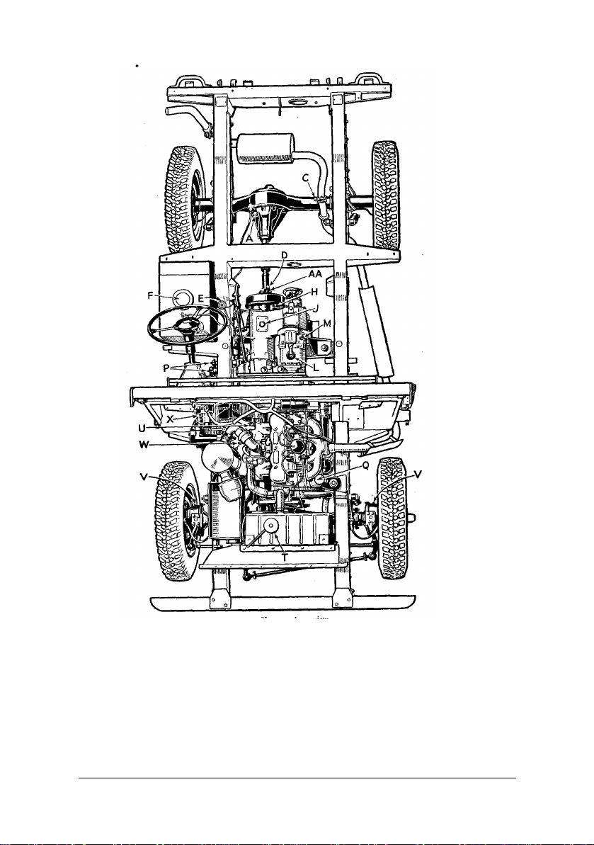
Fig. 4. Upper plan view.
A – Rear axle filler.
B – Rear axle drain plug.
C – Rear axle breather.
D – Propellor shaft sleeve lubrication nipple.
E – Brake fluid reservoir.
F – Petrol filler cap.
G – Petrol tank drain plug.
H – Transmission brake adjuster.
J – Transfer box filler.
K – Transfer box drain plug.
L – Main gearbox filler.
APRIL 1950 22
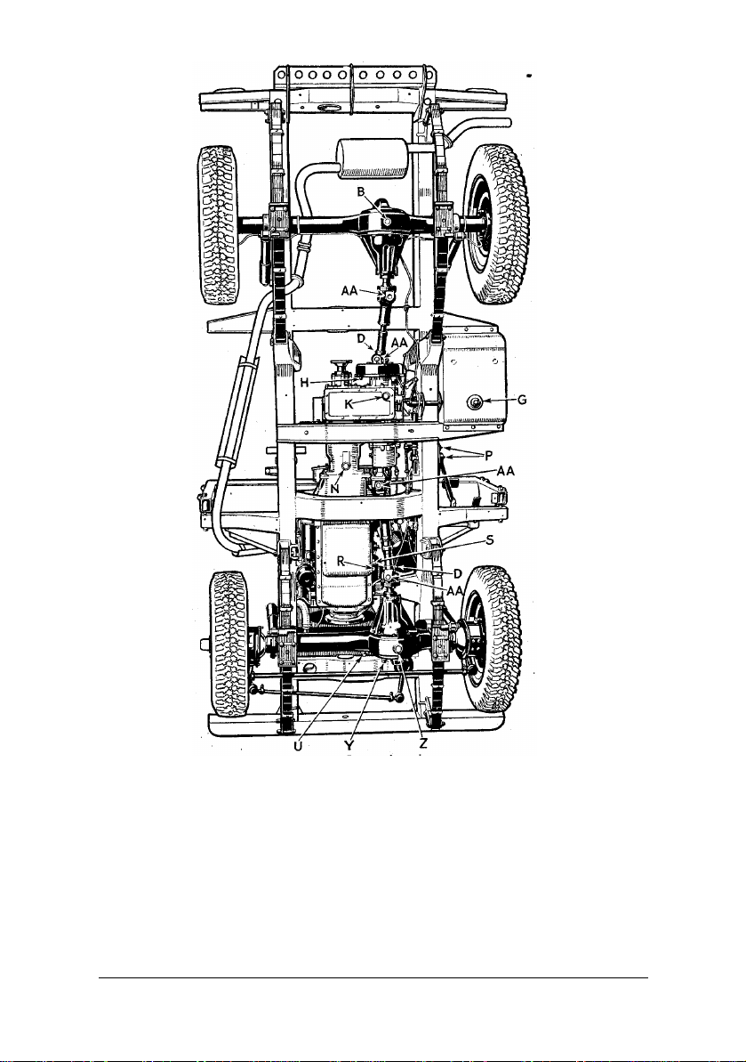
M – Main gearbox dipstick.
AA – Propellor shaft journal lubrication
N – Main gearbox drain plug.
P – Pedal lubricating nipples.
Q – Engine oil filter.
R – Engine drain plug.
S – Engine sump filter.
T – Radiator filler cap.
U – Coolant drain tap.
APRIL 1950 23
Fig. 5. Lower plan view.
V – Tracta joint level and filler plug.
W – Engine dipstick.
X – Steering box filler.
Y – Front axle filler.
Z – Front axle drain plug.
nipples.
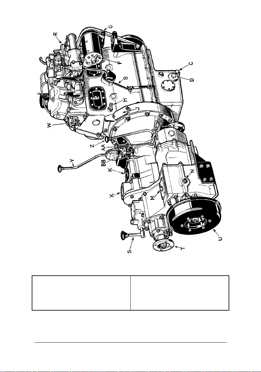
Fig. 6. Engine unit (right hand side).
A – Engine oil filler.
B – Oil level dipstick.
C – Oil drain plug.
D – Gauze Suction oil filter.
E – By-pass pressure oil filter.
F – Dynamo lubricator.
G – Fan belt adjustment.
H – Cylinder block drain tap.
J – Timing inspection cover.
K – Main gearbox oil filler.
L – Gearbox oil level dipstick
M – Transfer box oil filler.
APRIL 1950 24

Fig. 7. Engine unit (left hand side).
N – Transfer box oil level plug.
P – Oil pressure warning switch.
Q – Ignition control.
R – Thermostat housing.
S – Power take-off control.
T – Power take-off output.
U – Transmission brake (hand brake)
V – Clutch operation lever.
W – Mixture control warning light switch.
X – Main gearbox inspection cover.
Y – Main gear change lever.
Z – Transfer box change lever.
AA – Front wheel drive lock.
BB – Reverse stop adjustment.
APRIL 1950 25
 Loading...