

Page 1

Range Rover Sport
R
OWNER'S HANDBOOK
Publication Part No. LRL 10 02 62 141
XML to PDF by RenderX XEP XSL-FO Formatter, visit us at http://www.renderx.com/
Page 2
Introduction
L
ABOUT THIS HANDBOOK
Please take the time to study all of the owner/operator literature supplied with your vehicle as soon
as possible.
IMPORTANT
The information contained in this handbook covers all vehicle derivatives and optional equipment,
some of which may not be fitted to your vehicle. Due to printing cycles, this handbook may include
descriptions of options before they become generally available.
The vehicle options, hardware and software, are designed for the market in which the vehicle is
intended for original sale. If the vehicle is to be registered or used in another geographical area, it
may need modifications to suit local requirements. Land Rover is not responsible for the cost of
any modifications. Warranty conditions may be affected.
The information contained in this publication was correct when it went to print. Subsequent vehicle
design changes may result in a supplement being added to the literature pack. Updates can also be
viewed on the Land Rover internet site at; www.ownerinfo.landrover.com.
In the interest of development, the right is reserved to change specifications, design or equipment
at any time without notice and without incurring any obligations. This publication, or part thereof,
may not be reproduced nor translated without our approval. Errors and omissions excepted.
SYMBOLS USED IN THIS HANDBOOK
Safety warnings indicate either a procedure which must be followed precisely, or
information that should be considered with great care, in order to avoid the possibility
of personal injury.
Cautions indicate either a procedure which must be followed precisely, or information that
should be considered with great care, in order to avoid the possibility of damage to your
vehicle.
This recycling symbol identifies those items that must be disposed of safely in order to
prevent unnecessary damage to the environment.
This symbol identifies those items that must be disposed of correctly, as they contain
harmful substances. Seek advice on disposal from your Land Rover Dealer/Authorised
Repairer and/or your local authority.
This symbol identifies those features that can be adjusted, disabled or enabled by your
Dealer/Authorised Repairer.
©Jaguar Land Rover Limited 2013.
All rights reserved. Published by Jaguar Land Rover Limited.
2
XML to PDF by RenderX XEP XSL-FO Formatter, visit us at http://www.renderx.com/
Page 3

Contents
R
Introduction......................................2
Entering the vehicle..........................5
Exiting the vehicle...........................13
Front seats......................................17
Rear seats.......................................20
Head restraints...............................25
Steering wheel................................27
Seat belts........................................29
Child safety.....................................33
Airbags...........................................40
Instrument panel.............................45
Warning lamps...............................49
Exterior lights.................................53
Interior lights..................................56
Wipers and washers.......................58
Mirrors............................................61
Blind spot monitoring.....................63
Garage door opener........................67
Windows.........................................70
Touch screen..................................72
Heating and ventilation...................75
Storage compartments...................82
Load carrying..................................86
Towing............................................89
Starting the engine..........................97
Intelligent stop/start......................100
Eco-data........................................101
Gearbox........................................102
Stability control.............................106
Suspension...................................108
Brakes...........................................111
Parking aids..................................114
Park assist....................................119
Automatic speed limiter (ASL)......124
Cruise control...............................125
Adaptive cruise control.................126
Terrain response...........................133
Hill descent control (HDC)............135
Wade sensing...............................137
Cameras........................................139
Audio/video overview....................141
Radio............................................147
DAB radio.....................................149
Portable media..............................152
Television......................................158
Video media player.......................160
Dual view......................................162
Rear media...................................164
Voice control.................................168
Telephone.....................................171
Navigation system........................176
Fuel and refuelling........................193
Maintenance.................................199
Fluid level checks..........................214
Vehicle battery..............................220
Fuses............................................223
Tyres.............................................233
Tyre pressure monitoring system
(TPMS).........................................239
Tyre repair kit................................241
Wheel changing............................245
Vehicle recovery...........................251
After a collision.............................255
Vehicle labels................................256
Technical specifications................257
Type approval...............................268
Controls overview.........................298
3
XML to PDF by RenderX XEP XSL-FO Formatter, visit us at http://www.renderx.com/
Page 4

L
4
XML to PDF by RenderX XEP XSL-FO Formatter, visit us at http://www.renderx.com/
Page 5
UNLOCKING THE VEHICLE
R
Entering the vehicle
5
XML to PDF by RenderX XEP XSL-FO Formatter, visit us at http://www.renderx.com/
Page 6

Entering the vehicle
L
Any person fitted with an implanted
medical device should make sure that
the device is kept at a distance of at
least 22 cm (8.7 inches) away from any
transmitter mounted in the vehicle.
This is to avoid any possibility of
interference between the system and
the device.
Interference may cause the implanted
medical device to malfunction, causing
serious injury or death. For more
information on the locations of the
security system transmitters, see 265,
REMOTE KEY FOB TRANSMITTER
LOCATIONS.
To prevent accidental or unauthorised
operation, never leave the Smart key
unattended in the vehicle. Never leave
children or animals unattended in the
vehicle. The vehicle can be operated
when the Smart key is inside the
vehicle.
Note: The operational range of the Smart key
will vary considerably depending on
atmospheric conditions and interference from
other transmitting devices.
Note: If any door or the tailgate is locked or
unlocked 10 times within a short period, the
latch is disabled for approximately 1 minute.
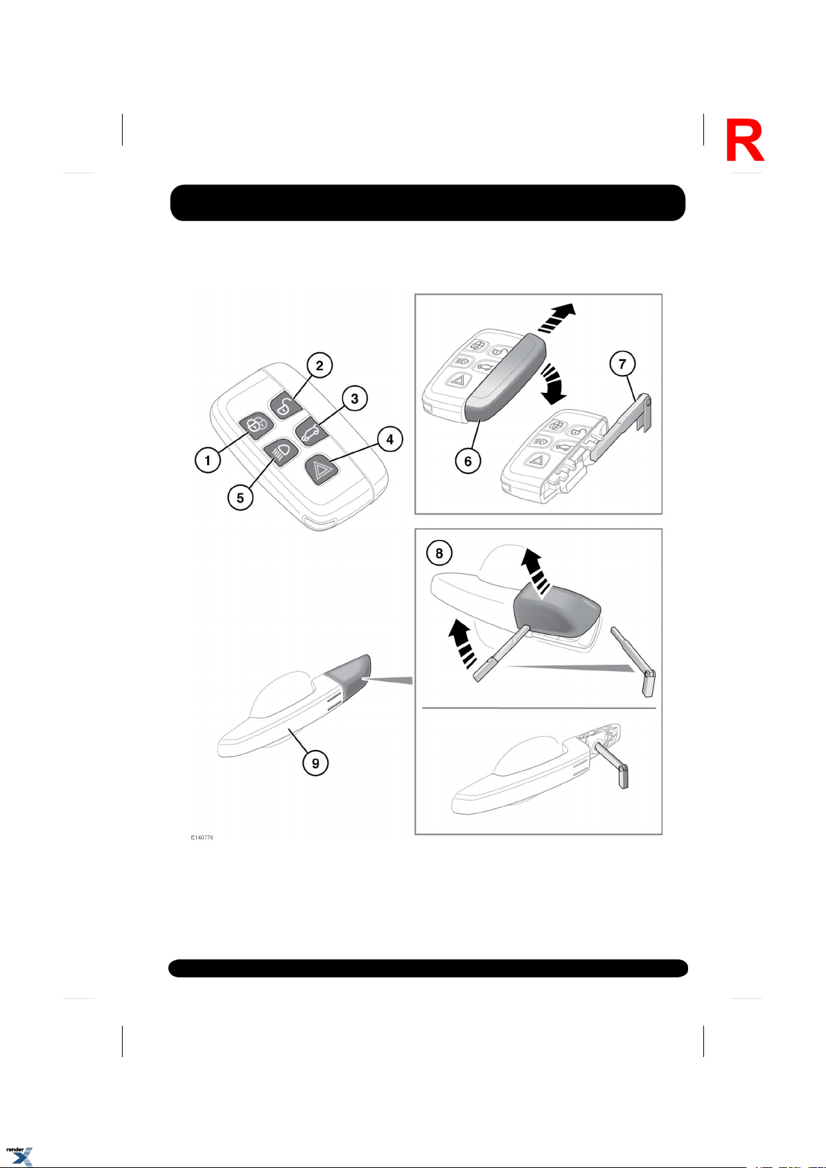
The vehicle is supplied with 2 Smart keys. The
Smart keys act as remote controls for the
locking and alarm system and allow the vehicle
to be locked, unlocked and driven without the
use of a conventional key. See 8, KEYLESS
ENTRY, 14, KEYLESS LOCKING and 97,
STARTING THE ENGINE. Each Smart key also
has an emergency key housed in a slide out
compartment.
1.
Lock:
• Press to secure the vehicle. The vehicle
can be Single or Double locked. See
13, SINGLE LOCKING and 13,
DOUBLE LOCKING.
Also see, 14, GLOBAL CLOSING.
2.
Unlock:
• Press briefly to unlock the vehicle and
deactivate the alarm. The hazard
warning lamps will flash twice to
indicate that the vehicle is unlocked and
the alarm has been deactivated. The
exterior lamps, interior lamps and
approach lamps will illuminate to assist
entry to the vehicle. Also see 8,
GLOBAL OPENING.
3.
Tailgate release/stop/reverse direction/close:
• Press briefly to open/close the tailgate.
If the vehicle is locked and armed, the
perimeter alarm will remain active while
the tailgate is open, but intrusion and
inclination sensing systems will be
disabled for the duration that the
tailgate is open.
When closing the tailgate, if the vehicle
is already locked and armed, the hazard
warning lamps will flash after a few
seconds to confirm the full alarm
system has been reactivated. There will
also be an audible sound if the vehicle
was double locked. See 9, OPENING
AND CLOSING THE TAILGATE.
Note: Make sure that the Smart key
does not remain in the vehicle before
closing. If the vehicle is in an area of
localised Radio Frequency (RF)
interference or the Smart key is
shielded by metal objects, the vehicle
may close and lock with no means of
opening again.
6
XML to PDF by RenderX XEP XSL-FO Formatter, visit us at http://www.renderx.com/
Page 7

4.
R
Panic alarm:
• Press and hold for 3 seconds (or press
3 times within 3 seconds) to activate
the horn and the hazard lamps.
• Once active for more than 5 seconds,
the alarm can be cancelled by pressing
the button and holding for 3 seconds
(or pressing 3 times within 3 seconds).
• The emergency alarm will also be
cancelled if a valid Smart key is present
when the START/STOP button is
pressed.
5.
Approach illumination:
• When approaching the vehicle during
darkness, press to switch on the
approach illumination. Press again to
turn the approach lamps off.
Note: In some markets a second press
of the button will turn on the headlamps
and reversing lamps. A third press will
be required to turn the lamps off.
• The approach illumination period set at
the factory is 30 seconds. This delay
period may be configured to provide
illumination lasting between 0 and 240
seconds. See 46, INSTRUMENT PANEL
MENU.
6.
Emergency key access: Slide open the side
cover to release, then remove.
7.
Remove the emergency key blade and
unfold.
8.
If the Smart key fails to open the vehicle,
insert the key blade into the slot at the base
of the driver's door lock cover and gently
lever the key blade upwards. Carefully rotate
the door lock cover upwards, to lever the
cover off the retaining clips. Insert the key
blade into the exposed lock and turn to
operate the lock. The alarm will sound.
Entering the vehicle
Note: When the driver's door is unlocked
using the key blade, the alarm will sound
until the Smart key is positioned correctly.
Note: A replacement Smart key can be
obtained only from a Land Rover
Dealer/Authorised Repairer. The Land Rover
Dealer/Authorised Repairer will require
proof of identification and ownership.
Notify a Land Rover Dealer/Authorised
Repairer immediately if a Smart key is lost
or stolen.
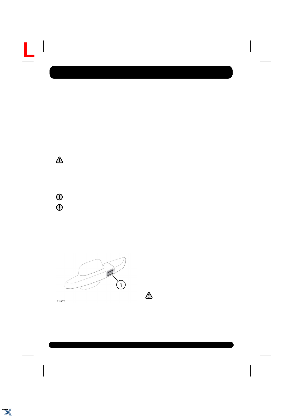
9.
Keyless entry/exit:
• Exterior door handles have separate
unlock and lock sensors. The unlock
sensor is located on the inner surface
of the handle.
SINGLE/MULTI-POINT ENTRY
When you press the unlock button, your vehicle
will unlock in 1 of 2 ways:
1.
Single Point Entry: Unlocks the driver's door
and fuel filler only. A second press is
required to unlock the remaining doors and
the tailgate.
2.
Multi-Point Entry: Unlocks all doors, fuel
filler flap and the tailgate on the first press.
To change from Single to Multi-Point entry (or
vice versa), press both the lock and unlock
buttons simultaneously for 3 seconds. The
hazard warning lamps will flash twice to confirm
the change.
This feature may also be set via the Vehicle
Set-Up menu. See 46, INSTRUMENT PANEL
MENU.
Note: If, when the vehicle is unlocked, an
audible warning is emitted, this will be a
‘Mislock’ error. There may be a fault with either
of the alarm sensors. Consult with your Land
Rover Dealer/Authorised Repairer as soon as
possible.
7
XML to PDF by RenderX XEP XSL-FO Formatter, visit us at http://www.renderx.com/
Page 8

Entering the vehicle
L
GLOBAL OPENING
Press and hold the unlock button for 3 seconds
to unlock the vehicle and open all windows.
To cancel global opening, press any of the
buttons on the Smart key or operate the driver’s
window switches. To stop a particular window
opening, operate the relevant window switch.
This feature can be enabled/disabled via the
Vehicle Set-Up menu (see 46, INSTRUMENT
PANEL MENU).
KEYLESS ENTRY
Keyless entry allows the vehicle to be opened
if a Smart key is within 1.0m (3ft) of the door
handle or the tailgate external switch.
Note: The Smart key may not be detected if it
is placed within a metal container or if it is
shielded by a device with a back-lit LCD screen,
such as a smart phone, laptop (including laptop
bag), games console etc. Keep the Smart key
clear of such devices when attempting Keyless
entry or Keyless starting.
Note: The Smart key needs only to be on the
driver’s person or in a non-metallic bag or
briefcase. It does not need to be exposed or
handled.
To enter the vehicle, just pull the door handle.
The alarm will be disarmed and the doors
unlocked according to the current unlock/entry
setting (Single or Multi-Point). The hazard
warning lamps will flash twice as ‘unlock’
confirmation. Power folded mirrors will fold out
(if enabled).
Note: If Single Point Entry is the current security
setting and a door other than the driver’s door
is opened first, all doors will unlock.
CONVENIENCE MODE
When the door is opened using either the Smart
key or keyless entry, the vehicle's electrical
system initiates the convenience mode. The
following systems become functional:
• Driver position memory.
• Seat and steering column adjustment.
• Interior and exterior lighting.
• Message centre.
• Auxiliary power socket.
STEERING COLUMN LOCK
The electric steering column lock will
lock/unlock when the vehicle is locked/unlocked.
If any malfunction of the steering column lock
occurs, a message will be displayed in the
Message centre. If this occurs:
1.
From the driver's seat, lock and then unlock
the vehicle using the Smart key.
2.
Try again to unlock the steering column
lock, by turning the steering wheel gently
to the left and right while locking and then
unlocking the vehicle using the Smart key.
3.
If the problem persists, seek qualified
assistance.
DRIVE-AWAY LOCKING
Drive-away locking automatically locks all the
doors when the vehicle is in motion. This feature
can be enabled/disabled via the Vehicle Set-Up
menu. See 46, INSTRUMENT PANEL MENU).
Note: Pressing the unlock or lock button on the
driver or front passenger door after Drive-away
locking has taken place, will override drive-away
locking for the current journey. See 15, DOOR
LOCKS AND RELEASE LEVERS.
8
XML to PDF by RenderX XEP XSL-FO Formatter, visit us at http://www.renderx.com/
Page 9
Entering the vehicle
R
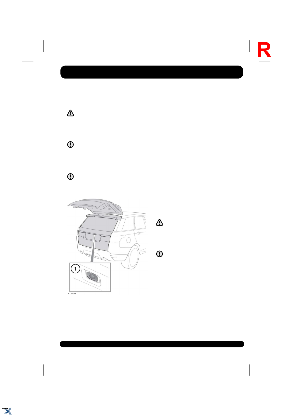
OPENING AND CLOSING THE TAILGATE
While the tailgate is open, the locking
latch is exposed. Do not attempt to
manually close the latch as it may also
automatically ‘soft close’ and trap
items or body parts.
Make sure there is minimum space of
1.5 metres (58 inches) above and at the
rear of vehicle before operating the
tailgate. Insufficient space may result in
damage to the vehicle.
Do not operate the tailgate if a cycle rack
is fitted to the tailgate. Remove any
cycles and/or racks before operating the
tailgate.
Note: The tailgate external release switch
will operate if all doors are unlocked and
the gear selector is in the Park (P) position.
If the gear selector is in the Neutral (N)
position, the switch will only operate if all
doors are unlocked, and the ignition is in
convenience mode or switched off. The
switch will not operate if the gear selector
is in any other position
The tailgate can also be released using the
following methods.
• The interior tailgate release switch. See 298,
DRIVER CONTROLS.
• The Smart key tailgate release switch. See
5, UNLOCKING THE VEHICLE.
Note: The tailgate will not open if the vehicle is
travelling at or above approximately 5 km/h (3
mph).
OPENING AND CLOSING THE POWERED TAILGATE
While the tailgate is open, the locking
latch is exposed. Do not attempt to
manually close the latch as it may also
automatically ‘soft close’ and trap
items or body parts.
1.
Tailgate release. Lift the tailgate to open.
Do not operate the tailgate if a cycle rack
is fitted to the tailgate. Remove any
cycles and/or racks before operating the
tailgate.
9
XML to PDF by RenderX XEP XSL-FO Formatter, visit us at http://www.renderx.com/
Page 10
Entering the vehicle
L
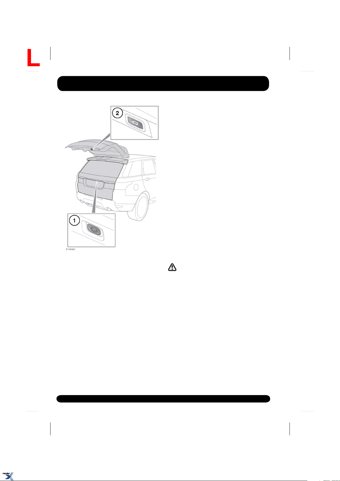
1.
Tailgate open/close using the exterior
button. Press to open, stop, reverse
direction or close the tailgate.
Note: The tailgate external release switch
will operate if all doors are unlocked and
the gear selector is in the Park (P) position.
If the gear selector is in the Neutral (N)
position the switch will only operate if all
doors are unlocked, and the ignition is in
convenience mode or switched off. The
switch will not operate if the gear selector
is in any other position.
2.
Tailgate close. Press to close/stop the
tailgate.
The tailgate can also be opened or closed using
the following methods.
• The interior tailgate release switch. See 298,
DRIVER CONTROLS.
• The Smart key tailgate release switch. See
5, UNLOCKING THE VEHICLE.
After the tailgate has opened to its set height,
it can be manually raised or lowered. If the
tailgate fails to open or close correctly, close it
manually then press the tailgate release switch
again.
As the closing tailgate approaches the closed
position, it will ‘soft close’ to the fully-closed
position. If the vehicle was previously locked,
the alarm will re-arm. The hazard warning lamps
will flash to confirm the alarm status. An audible
confirmation may also be given.
Note: If a tailgate switch is pressed while the
tailgate is opening or closing, all movement will
stop. However, if a switch is pressed during the
‘soft close’ stage, the open request will be
ignored.
Note: The tailgate has a minimum closing
height, below which it will not power close.
Open the tailgate manually, or using a release
switch, to the fully open position and then press
the tailgate complete close button.
Before operating the tailgate, make
sure that anyone in the vicinity does
not have any part of their body in a
position where it could be trapped.
Note that the ‘soft close’ action does
not incorporate object detection. Death
or serious injury could occur, even with
an object detection system.
Object detection while opening: If an object is
detected that would interfere with the tailgate
opening, tailgate movement will stop. Remove
any obstructions and press the tailgate switch
again to open.
10
XML to PDF by RenderX XEP XSL-FO Formatter, visit us at http://www.renderx.com/
Page 11

Entering the vehicle
R
Object detection while closing: If an object is
detected that would interfere with a tailgate
closing, tailgate movement will stop and then
reverse to the fully open position if able to do
so. An audible warning will be given to indicate
a mislock. Remove any obstructions and if the
tailgate is open, press the tailgate switch again
to close the tailgate. If the tailgate is not open,
press a tailgate release switch to open the
tailgate, remove any obstructions. Once the
obstructions have been removed, press the
tailgate close switch to close the tailgate.
While the tailgate is open, the locking
platform and latch are exposed. Do not
manually close the latch as it may also
automatically ‘soft close’ and trap items
or body parts.
TAILGATE OPENING HEIGHT
It is possible to set the maximum height to
which a powered tailgate will open. This is
useful in parking areas with very low roofs or
just for ease of use.
1.
Open the tailgate to the position which you
want to set as the maximum height.
Press the tailgate open button to stop
movement or position manually once all
movement has stopped.
2.
Make sure that the tailgate is stationary for
at least 3 seconds.
3.
To set the opening height: Press and hold
the tailgate close button, on the tailgate,
until you hear a chime.
4.
Close the tailgate, then open again to check
that it opens to the programmed height.
Note: If, after performing part 3 of the process
the tailgate closes automatically, the required
height has not been set. Repeat the process
making sure all steps are adhered to.
To reset the maximum opening height to full,
repeat the process, but manually move it to the
fully open position before pressing and holding
the button.
The powered tailgate may lose its position
memory if there are multiple object detections
or if the battery voltage is low. Powered
operation may be inhibited.
To reset the tailgate:
1.
Manually close the tailgate.
2.
Press a tailgate release switch.
3.
Allow the tailgate to power fully open or to
the previously set position.
4.
Press and release the close switch.
5.
Allow the tailgate to power close fully.
The tailgate programmed position memory will
now be restored.
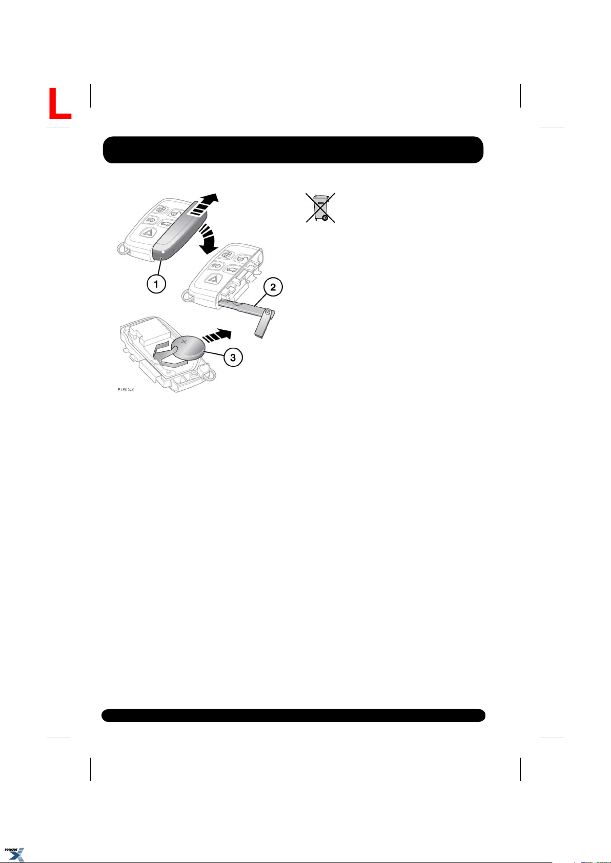
REMOTE KEY FOB BATTERY REPLACEMENT
When the battery needs replacing, there will be
a significant decrease in the effective range and
SMART KEY BATTERY LOW will be displayed
in the Message centre.
11
XML to PDF by RenderX XEP XSL-FO Formatter, visit us at http://www.renderx.com/
Page 12
Entering the vehicle
L
To replace the battery:
1.
Remove the cover by sliding in the
directions of the arrows.
2.
Use the emergency key blade to separate
the Smart key body.
3.
Fit a new and unused CR2032 type battery
(available from a Land Rover
Dealer/Authorised Repairer) with the
positive (+) side upwards.
Note: Avoid touching the new battery.
Moisture/oil from fingers can reduce battery life
and corrode the contacts.
Note: If the low battery warning does not
extinguish this indicates that the replacement
battery is not in a new and unused condition.
Refit the parts in reverse order, making sure
they click securely into place.
Battery disposal: Batteries contain
harmful substances and must be
disposed of correctly. Seek advice
on disposal from a Land Rover
Dealer/Authorised Repairer and/or
your local authority.
12
XML to PDF by RenderX XEP XSL-FO Formatter, visit us at http://www.renderx.com/
Page 13

Exiting the vehicle
R
SINGLE LOCKING
Press the lock button on the Smart key briefly
to single lock the vehicle and activate the
perimeter alarm. The hazard warning lamps will
flash to confirm.
Single locking secures the vehicle and prevents
the doors from being opened from the outside.
The doors may still be unlocked and opened
from inside the vehicle. In this state, only the
perimeter alarm is activated. See 13,
PERIMETER ALARM.
Note: This setting should be used in
circumstances, such as travelling on a ferry,
when pets are to be left in the vehicle, or if a
window must be left open etc.
Note: Always secure your vehicle when left
unattended. Where possible, always secure your
vehicle to the maximum available level of
security.
DOUBLE LOCKING
Never double lock the vehicle with
people, children, or pets inside. In the
event of an emergency they would be
unable to escape and the emergency
services would be unable to release
them quickly.
Press the lock button on the Smart key twice
within 3 seconds to double lock the vehicle and
activate the full alarm system. The hazard
warning lamps will flash twice to confirm and
a double lock tone will sound..
Double locking secures the vehicle and prevents
the doors being opened from inside or outside
of the vehicle. The doors cannot be unlocked
or opened from inside the vehicle when double
locked.
This provides extra security if the vehicle is left
unattended. The vehicle cannot be opened by
breaking a window and operating the door locks
from inside. Additionally, double locking also
activates the full alarm system. See 13, FULL
ALARM.
Note: In this state, an open window or sunroof
will cause the alarm to sound due to the
movement of air currents. For this reason, make
sure that all windows and the sunroof are fully
closed before double locking the vehicle.
PERIMETER ALARM
The perimeter alarm system is activated when
the vehicle is single locked. See13, SINGLE
LOCKING. Once activated, the alarm system will
sound if;
• the bonnet, tailgate or a door is opened.
• the engine START/STOP button is pressed
without a valid Smart key present.
If the vehicle is fitted with a battery backed-up
sounder, the sounder will sound if the battery
is disconnected, or an attempt is made to
disconnect the sounder.
FULL ALARM
The full alarm system is activated when the
vehicle is double locked. See 13, DOUBLE
LOCKING. Once activated the alarm system will
sound if:
• The bonnet, tailgate or a door are opened.
• Movement is detected within the vehicle
interior.
• The vehicle is raised or tilted.
If the vehicle is fitted with a battery backed-up
sounder, the alarm system will also sound if:
• The vehicle battery is disconnected.
• An attempt is made to disconnect the
battery backed-up sounder.
13
XML to PDF by RenderX XEP XSL-FO Formatter, visit us at http://www.renderx.com/
Page 14
Exiting the vehicle
L
INTERIOR PROTECTION
The interior protection feature of the full alarm
system may be temporarily disabled via the
Vehicle Set-Up menu. See 46, INSTRUMENT
PANEL MENU.
Note: Once disabled, this setting will be
re-enabled the next time the vehicle is double
locked with the Smart key.
KEYLESS LOCKING
Never double lock the vehicle with
people, children or pets inside. In the
event of an emergency they would be
unable to escape and the emergency
services would be unable to release
them quickly.
The vehicle will not lock automatically.
The Smart key may not be detected if it
is placed within a metal container or if
it is shielded by a device with a back-lit
LCD screen, such as a smart phone,
laptop (including in a laptop bag), games
console etc.
Note: Loose coins in the same pocket as the
Smart key may also affect its detection.
• To single lock the vehicle touch only the
keyless locking sensor (1) once without
grabbing the door handle.
Note: Do not place your fingers around the
back of the door handle while touching the
sensor. Doing so will prevent the vehicle
from locking.
• The hazard warning lamps will flash once
to confirm locking and the power fold
mirrors will fold in (if enabled).
• To double lock the vehicle, touch only the
keyless locking sensor (1) twice within 3
seconds.
Note: Do not place your fingers around the
back of the door handle while touching the
sensor. Doing so will prevent the vehicle
from locking.
• The hazard warning lamps will flash twice
accompanied by an audible sound to
confirm locking .
Note: When locking the vehicle via Keyless
locking, if a valid key is not present, 1 or more
of the doors, the bonnet or the tailgate is not
fully closed, or the ignition is ON, the vehicle
will NOT lock. There will be NO audible mislock
error warning. The hazard warning lamps will
NOT flash and the door mirrors (if enabled) will
NOT fold in. Check that all doors, the bonnet
and the tailgate are closed properly. Make sure
that the ignition is turned OFF and lock the
vehicle again. If the mislock persists, consult a
Dealer/Authorised Repairer.
Note: Keyless locking will activate only if the
Smart key is detected outside the vehicle. If no
Smart key is present, no locking will occur.
14
XML to PDF by RenderX XEP XSL-FO Formatter, visit us at http://www.renderx.com/
GLOBAL CLOSING
Make sure that no children, pets, or
obstructions are in any open aperture
before operating global closing. Safety
mechanisms are in place to prevent
serious injury, however injuries can
still occur.
Page 15
Press and hold the lock button on the Smart
R
key for 3 seconds. The vehicle will single lock
and the perimeter alarm will be activated
immediately. After 3 seconds any open windows
and the sunroof will be closed. Press the lock
button twice in 3 seconds to double lock the
vehicle.
This feature can be enabled/disabled via the
Vehicle Set-Up menu. See 46, INSTRUMENT
PANEL MENU.
With a valid Smart key present, press and hold
the keyless locking sensor (if fitted) on any
exterior door handle. The vehicle will single lock
and the perimeter alarm will be activated
immediately. After approximately 3 seconds,
any open windows and the sunroof will begin
to close.
Keep the keyless locking sensor pressed until
all open windows and the sunroof are fully
closed. Releasing the keyless locking sensor
will stop all window and sunroof movement.
When all windows and sunroof are closed,
release and then press the keyless locking
sensor to confirm the vehicle is single locked.
Alternatively, press the keyless locking sensor
twice within 3 seconds to double lock the
vehicle.
This feature can be enabled/disabled via the
Vehicle Set-Up menu. See 46, INSTRUMENT
PANEL MENU.
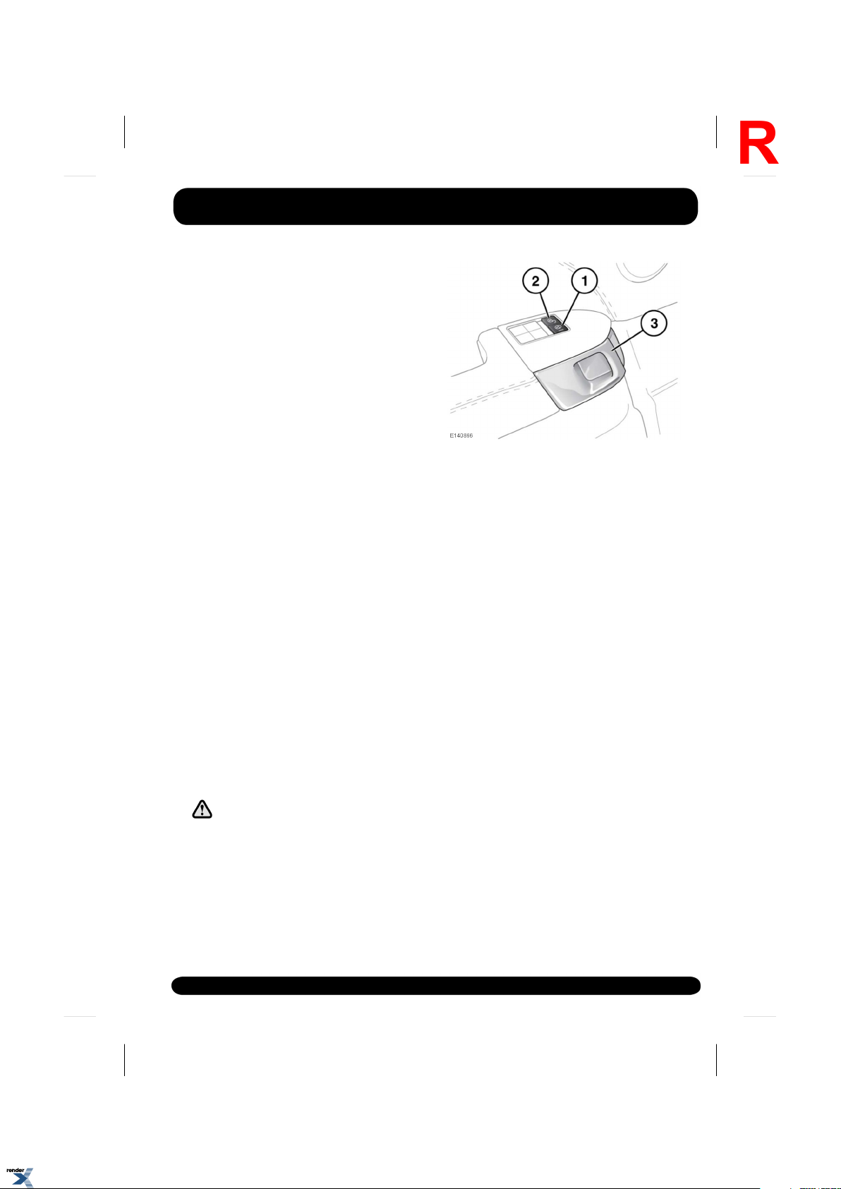
DOOR LOCKS AND RELEASE LEVERS
While a door is open, the locking latch
is exposed. If your vehicle is fitted with
the soft close feature, do not attempt
to manually close the latch as it may
also automatically ‘soft close’ and trap
items or body parts.
Exiting the vehicle
1.
Lock:
• With all doors closed, press any lock
button to lock all doors.
2.
Unlock:
• Press any unlock button to unlock all
doors. Alternatively, pull either front
door release handle (3) once to unlock
all doors.
• Pull either rear door release handle (3)
once to unlock the individual rear door.
Note: All unlock buttons are inhibited when
the vehicle is locked with the Smart key.
3.
Door release handle: pull to unlock and
open the door(s). If the door is locked,
pulling either front door handle once will
unlock all doors. Pulling either rear door
handle once will unlock the individual rear
door.
Note: The rear child security feature will
inhibit the rear door lock (1) and unlock (2)
switches, and the door release handles (3).
33, CHILD SAFETY LOCKS
15
XML to PDF by RenderX XEP XSL-FO Formatter, visit us at http://www.renderx.com/
Page 16
Exiting the vehicle
L
MISLOCK
When attempting to lock the vehicle with the
Smart key, if a valid key isn't present, if 1 or
more of the doors, the bonnet or the tailgate is
not fully closed or the ignition is ON, the vehicle
will NOT lock and an audible warning will sound
twice. Make sure the ignition is turned off and
lock the vehicle again. The vehicle will NOT fully
lock until all doors, the bonnet and the tailgate
are completely closed.
An audible mislock warning will also sound if
on locking, the system detects a lock or latch
failure. If the mislock persists, consult your
Dealer/Authorised Repairer.
DEACTIVATING THE ALARM WHEN TRIGGERED
If the alarm has been triggered it can be
deactivated by pressing the Smart key unlock
button, or by positioning the Smart key against
the steering column and pressing the engine
START/STOP button. See 98, KEYLESS START
BACKUP.
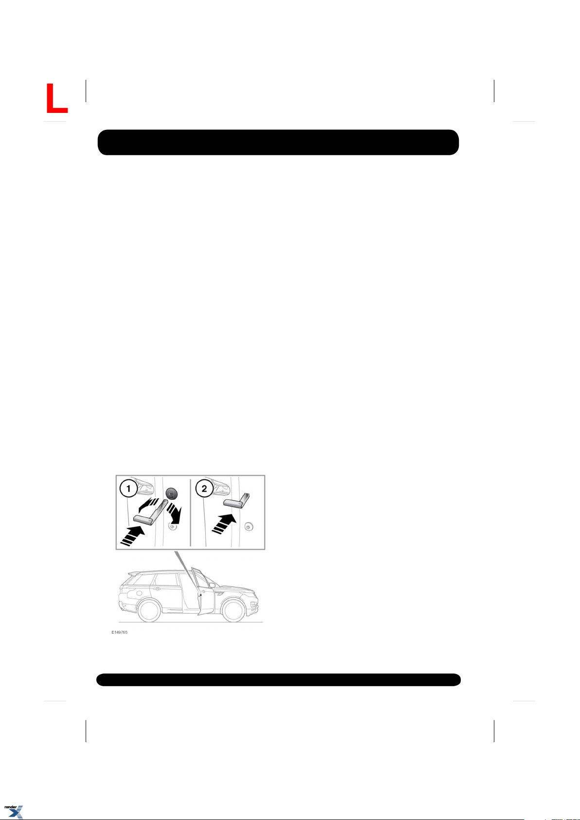
EMERGENCY LOCKING
In the event of the battery discharging or a fault
with the keyless locking system, the doors must
be locked manually.
Note: Do not leave the emergency key blade in
the vehicle at any point during the emergency
locking procedure.
1.
Open the door and locate the emergency
lock access cover. Using the emergency key
blade (see 5, UNLOCKING THE VEHICLE)
rotate the cover to release it from the door.
Remove the cover and store it safely.
2.
Insert the emergency key blade firmly into
the emergency lock.
The emergency key blade can now be
removed.
3.
Refit the emergency lock access cover and
rotate it clockwise to secure it firmly.
4.
Close the door and check to make sure the
door is locked.
Repeat the procedure for all other unlocked
doors.
16
XML to PDF by RenderX XEP XSL-FO Formatter, visit us at http://www.renderx.com/
Page 17
ELECTRIC SEATS
R
Front seats
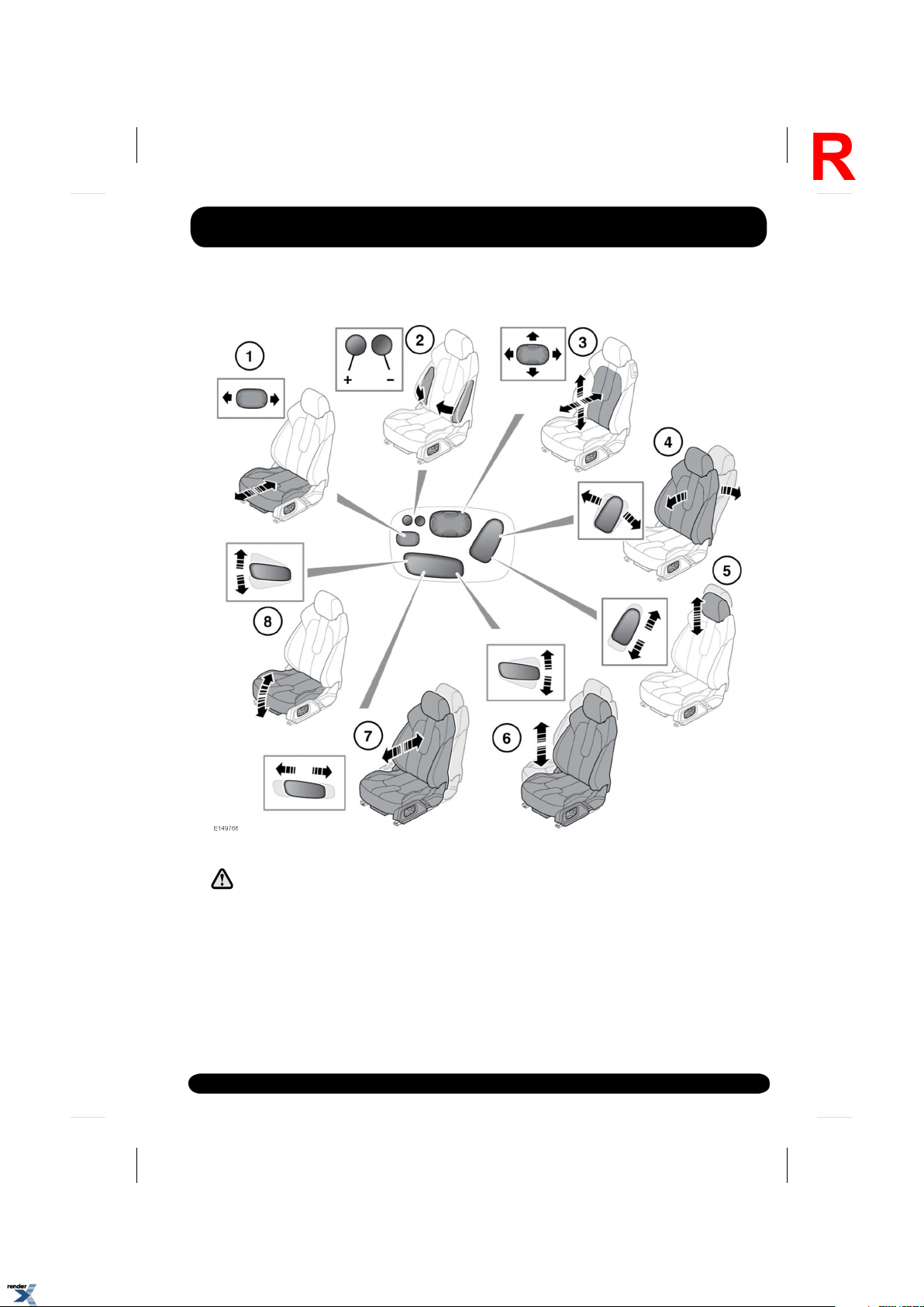
3.
Do not adjust the seat while the vehicle
is moving. Doing so could cause loss
of vehicle control and personal injury.
Note: This diagram covers all electric seat
controls. Not all of these controls apply to all
seats.
1.
Cushion length.
2.
Bolster inflate/deflate.
XML to PDF by RenderX XEP XSL-FO Formatter, visit us at http://www.renderx.com/
Lumbar support.
4.
Seat back angle.
5.
Head restraint height.
6.
Seat height.
7.
Forward and rearward position.
8.
Cushion tilt.
The front seats can also have:
17
Page 18
Front seats
L
• Heated/climate control (see 75, CLIMATE
CONTROL).
RESTRICTED FRONT SEAT TRAVEL
If seat movement stops unexpectedly
during adjustment, check for and
remove any obstructions.
Once any obstructions have been removed, the
seat adjustment mechanism can be reset as
follows:
Operate the button again to continue the stalled
adjustment. When seat movement resumes,
hold the button until the end of travel in that
direction has been reached. Seat adjustment
can now be carried out as normal.
Note: If no obstructions can be seen, but normal
adjustment cannot be carried out without
stalling, contact your Land Rover
Dealer/Authorised Repairer.
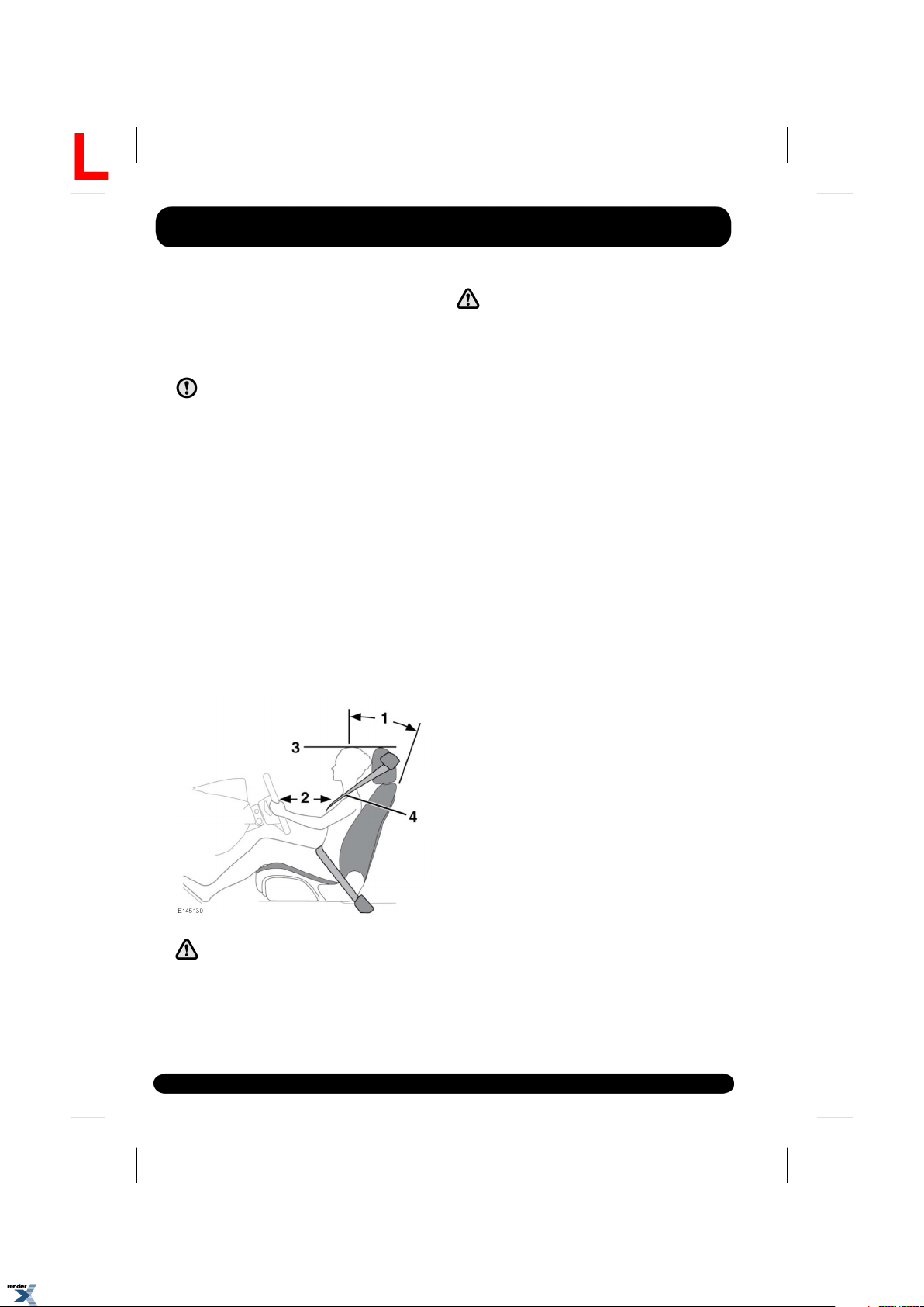
SITTING IN THE CORRECT POSITION
Do not adjust the seat while the vehicle
is moving.
The seat, head restraint, seat belt and airbags,
all contribute to the protection of the user.
Correct use of these components will give you
greater protection. Therefore, you should always
observe the following points:
1.
Sit in an upright position, with the base of
your spine as far back as possible. To
achieve optimum benefit of the seat belt in
the event of an accident, do not recline the
seat excessively.
2.
Do not move the driver's seat too close to
the steering wheel. Ideally, a minimum
distance of 254 mm (10 inches) is
recommended between the breastbone and
the steering wheel airbag cover. Hold the
steering wheel in the correct position, with
your arms slightly bent.
3.
Adjust the head restraint so that the top of
the head restraint is the same height as the
top of the head.
4.
Position the seat belt so that it is mid-way
between your neck and your shoulder. Fit
the strap tightly across your hips, not
across your stomach.
Make sure that your driving position is
comfortable and enables you to maintain full
control of the vehicle
The driver and front seat passenger
must not ride with the seat fully
reclined.
18
XML to PDF by RenderX XEP XSL-FO Formatter, visit us at http://www.renderx.com/
Page 19
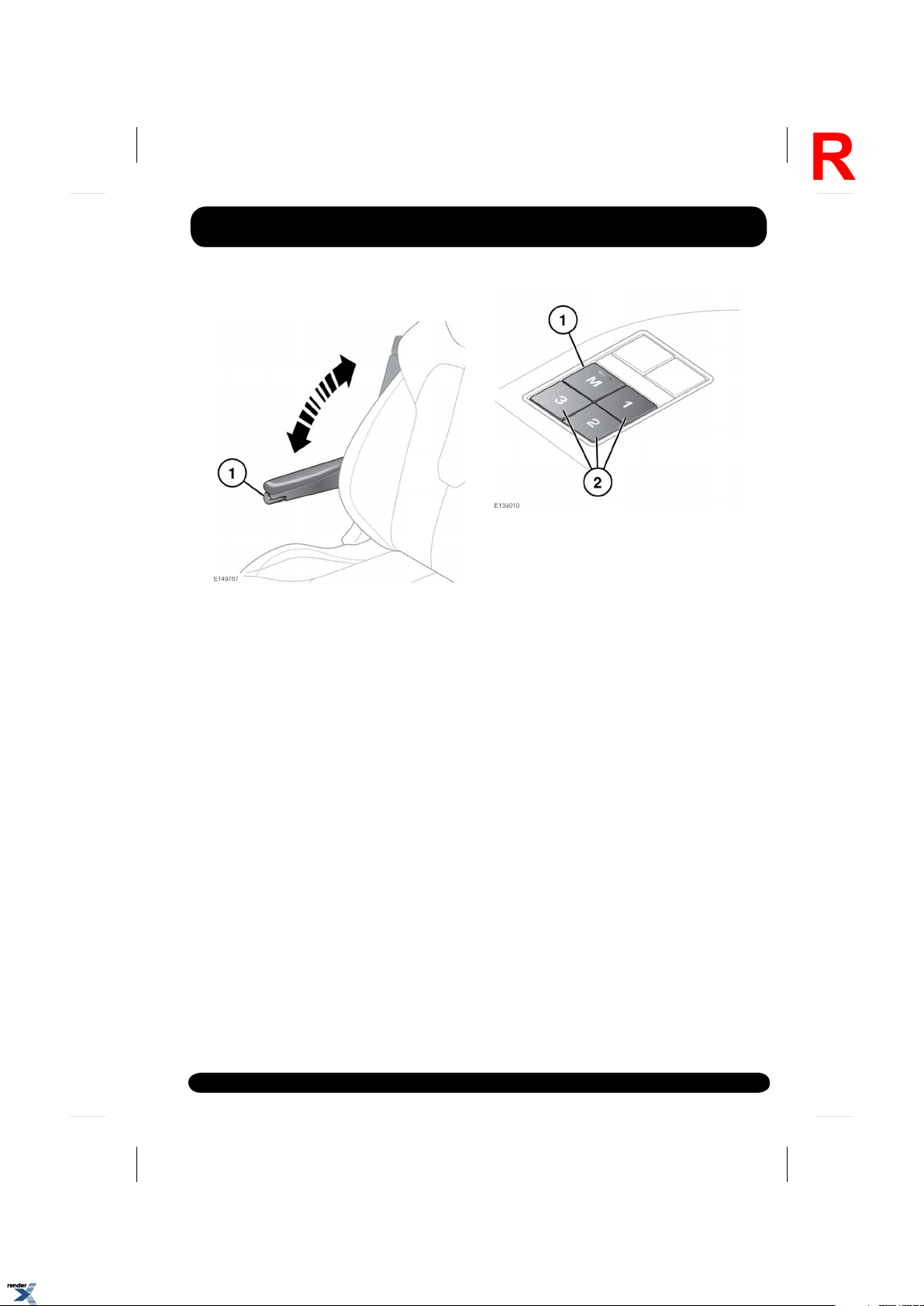
FOLDING ARMREST
R
Use the adjuster wheel (1) to set the required
height. The folding armrest may be stowed by
moving to the vertical position.
SEAT POSITION MEMORY
Once you have adjusted the power operated
driver's seat, steering column (see 27,
ADJUSTING THE STEERING WHEEL) and
exterior mirrors (see 61, EXTERIOR MIRRORS)
for your ideal driving position, the settings can
be stored for future use.
Passenger seat position can also be changed,
follow the same procedure as for the driver's
seat. Press the memory button to store the
current seat settings.
Front seats
1.
Press the memory store (M) button to
activate the memory function.
2.
Press 1 of the preset buttons within 5
seconds to store the current settings.
MEMORY (1, 2 or 3) SETTINGS SAVED will
be displayed in the Message centre,
accompanied by an audible chime to
confirm the settings have been stored.
Note: A seat position will only be stored
during the 5 second active period.
Note: Any existing settings will be
over-written when storing a new position.
3.
To recall a stored position, press the
relevant preset button. MEMORY (1, 2 OR
3) RECALLED will be displayed in the
Message centre.
Note: The memory function for all passenger
seats will not trigger any messages in the
Message centre.
19
XML to PDF by RenderX XEP XSL-FO Formatter, visit us at http://www.renderx.com/
Page 20
Rear seats
L
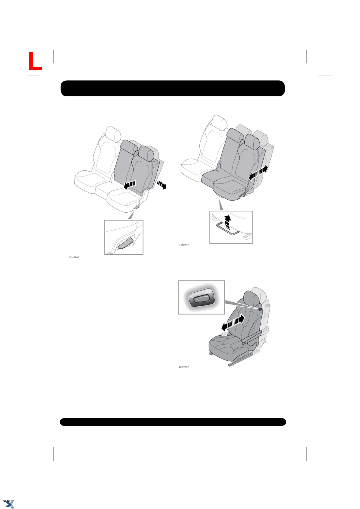
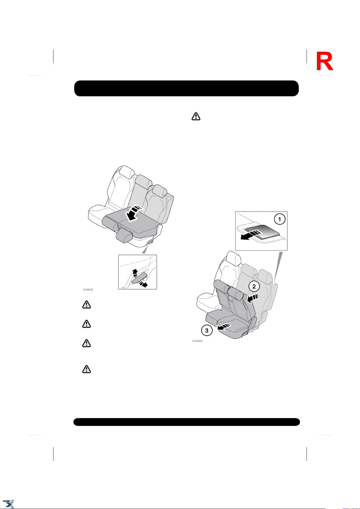
MANUAL SEATS
Forward and back adjustment.
To adjust the angle of the seat back:
1.
Lift the adjustment lever.
2.
Adjust the seat back to the desired angle.
3.
Release the adjustment lever.
20
PASSENGER SEAT AWAY
Use the switch for forward or rearward
adjustment.
XML to PDF by RenderX XEP XSL-FO Formatter, visit us at http://www.renderx.com/
Page 21
Rear seats
R
The front passenger seat position can be
adjusted to provide more space for rear seat
occupants.
FOLDING AND RAISING THE REAR SEATS
Make sure the head restraints are
raised to the correct position before
the seats are used by a passenger.
Raise the release lever. The seat back will fold
down against the seat cushion. Lift the seat back
to raise to the upright position and make sure
the seat back is locked firmly in position.
The split fold rear seat can be folded completely
to accommodate large loads, or partially to
accommodate large loads and still retain seating
for passengers.
REAR SEAT ACCESS
Always make sure that objects carried
in the vehicle are secured properly.
Never allow passengers to travel in the
load space under any circumstances.
Make sure that when the seat back is
raised, the locking mechanism is fully
engaged.
When raising the rear seats, make sure
the seat belts are correctly routed in
the seat belt guides and not trapped
behind the seats.
To access the third row seats.
1.
Pull the seat back lever forwards.
2.
Fold the seat back forward.
3.
Slide the seat forwards.
21
XML to PDF by RenderX XEP XSL-FO Formatter, visit us at http://www.renderx.com/
Page 22

Rear seats
L
To return the seat to the upright position, slide
the seat rearward and raise the seat back until
the latching mechanism clicks into position.
Make sure that when the seat back is
raised, the locking mechanism is fully
engaged.
When raising the rear seats, make sure
that seat belts are correctly routed in
the seat belt guides and not trapped
behind the seats.
Make sure the head restraints are
raised to the correct position before
the seats are used by a passenger.
22
XML to PDF by RenderX XEP XSL-FO Formatter, visit us at http://www.renderx.com/
Page 23
FOLDING AND RAISING THE THIRD ROW SEATS
R
Rear seats
To avoid injury, the loadspace cover
must not be left in the installed
position when the third row seats are
occupied.
Beware of trapping fingers when
raising and lowering the third row seat.
XML to PDF by RenderX XEP XSL-FO Formatter, visit us at http://www.renderx.com/
When raising the rear seats, make sure
the seat belts are correctly routed into
the seat belt guides and not trapped
behind the seats.
23
Page 24

Rear seats
L
Make sure nothing has been left under
the third row seat, or in the footwell,
when folding down the seat, as this
could cause damage to the item or the
seat.
Always make sure that objects carried
in the vehicle are secured properly.
Never allow passengers to travel in the
load space, under any circumstances.
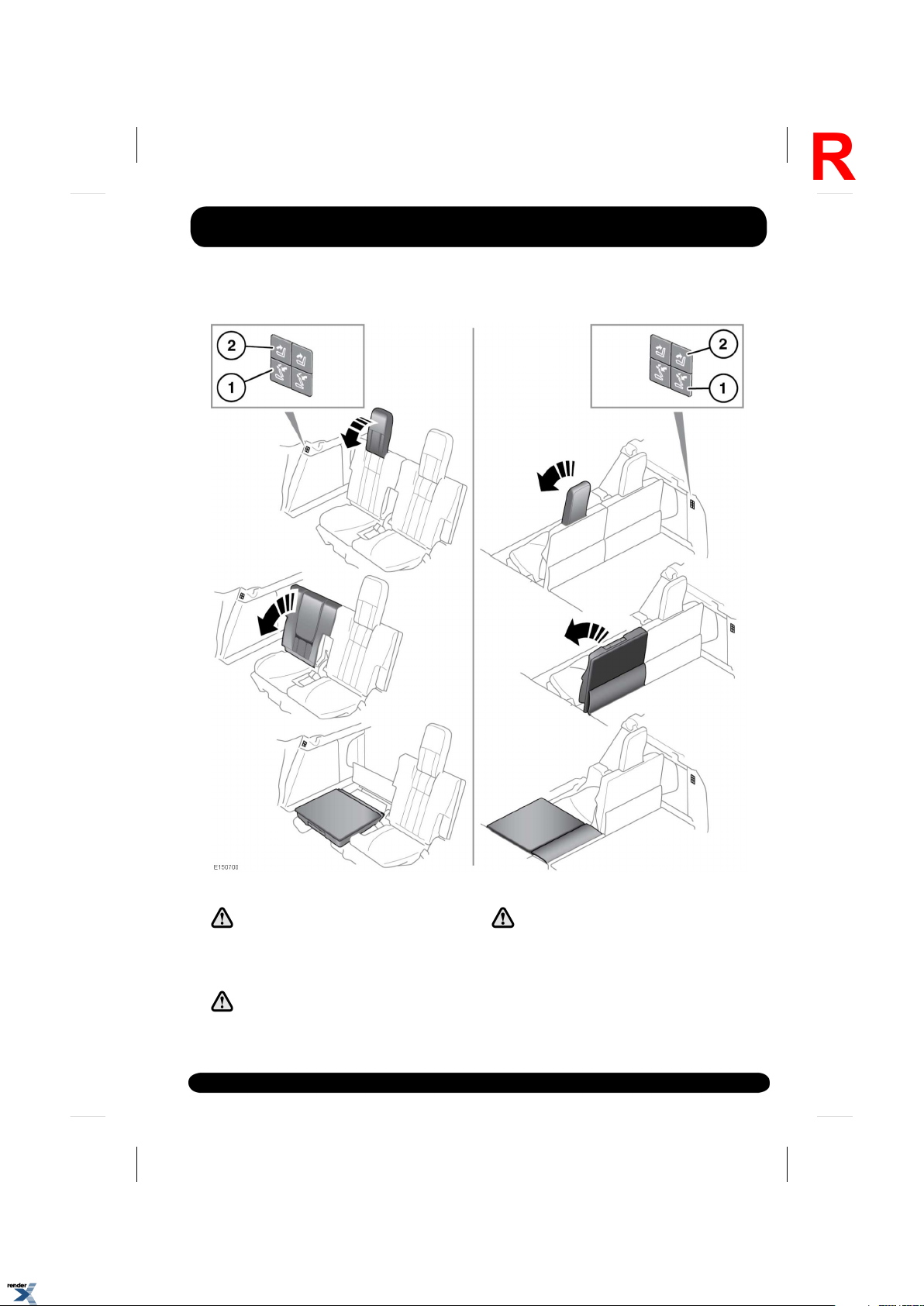
The third row seats can be folded or raised
individually using the buttons located behind
the second row seats or the side of the
loadspace.
Note: The loadspace cover must be removed
before folding or raising the third row seats.
This can be stored in the loadspace.
1.
To fold: Press the button once, to fold the
head restraint fully downwards. Press the
button once again and the seat back will
fold.
2.
To raise: Press to raise the seat back to the
upright position.
3.
Manually raise the head restraint until it
latches into position.
Note: If the electric seats are operated more
than 3 times through the full fold/raise sequence
in quick succession, the system will be disabled
for 2 minutes.
RESTRICTED REAR SEAT TRAVEL
If electric seat movement stops
unexpectedly during folding or raising,
check for and remove any obstructions.
Once any obstructions have been removed,
continue the seat movement by pressing the
appropriate fold/raise button.
Note: If no obstructions can be seen, and
normal movement cannot be carried out,
contact your Dealer/Authorised Repairer.
The head restraint must always be
raised when using the third row seats.
Make sure that when the head restraint
is raised, the locking mechanism is
fully engaged.
The head restraint must always be folded
down before folding the seat back.
24
XML to PDF by RenderX XEP XSL-FO Formatter, visit us at http://www.renderx.com/
Page 25
Head restraints
R
HEAD RESTRAINTS
Adjust, so that the top of the head
restraint is the same height as the top
of the seat occupant's head. Incorrect
adjustment increases the risk of death
or serious injury in the event of a
collision.
Do not drive, or carry passengers with
the head restraints removed from
occupied seats. The absence of a
correctly adjusted head restraint
increases the risk of neck injury in the
event of a collision.
Never adjust the head restraints while
the vehicle is in motion.
Always store a removed head restraint
securely.
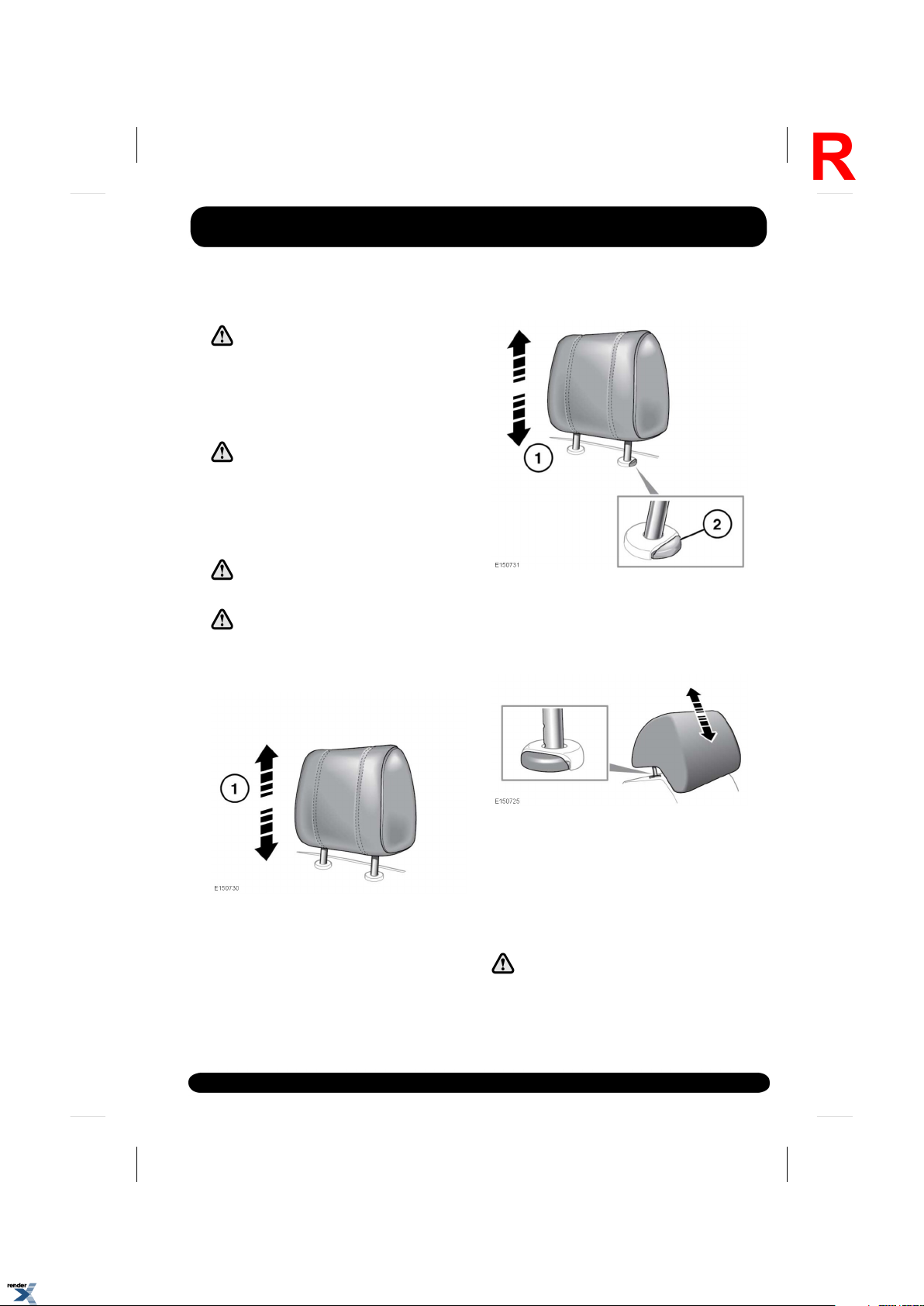
ELECTRIC HEAD RESTRAINTS
MANUAL HEAD RESTRAINTS
1.
To raise, pull the head restraint upwards. It
will click and lock in position.
2.
To lower, depress the locking button and
push down on the restraint.
1.
To adjust the height of the head restraint.
See 17, ELECTRIC SEATS.
Note: It is not possible to remove electric
head restraints.
1.
To raise, pull the head restraint upwards. It
will click and lock in position.
2.
To lower, depress the locking button and
push down on the restraint.
HEAD RESTRAINT REMOVAL
Always store a removed head restraint
securely.
25
XML to PDF by RenderX XEP XSL-FO Formatter, visit us at http://www.renderx.com/
Page 26

Head restraints
L
Do not drive, or carry passengers with
the head restraints removed from
occupied seats. The absence of a
correctly adjusted head restraint
increases the risk of neck injury in the
event of a collision or sudden stop.
Manual head restraints may be removed, if
required (e.g. to fit larger child seats).
1.
Raise the head restraint to its uppermost
position and press the locking collar.
2.
Lift the restraint out of the seatback
Make sure the head restraint is refitted before
the seat is used by a passenger.
1.
Make sure the restraint is facing the correct
direction.
2.
Insert the stems of the head restraint into
the sockets on the seatback.
3.
Push the restraint downwards until at least
the first click.
Note: See 36, RECOMMENDED CHILD SEATS,
for details on correct child restraint installation
26
XML to PDF by RenderX XEP XSL-FO Formatter, visit us at http://www.renderx.com/
Page 27
Steering wheel
R
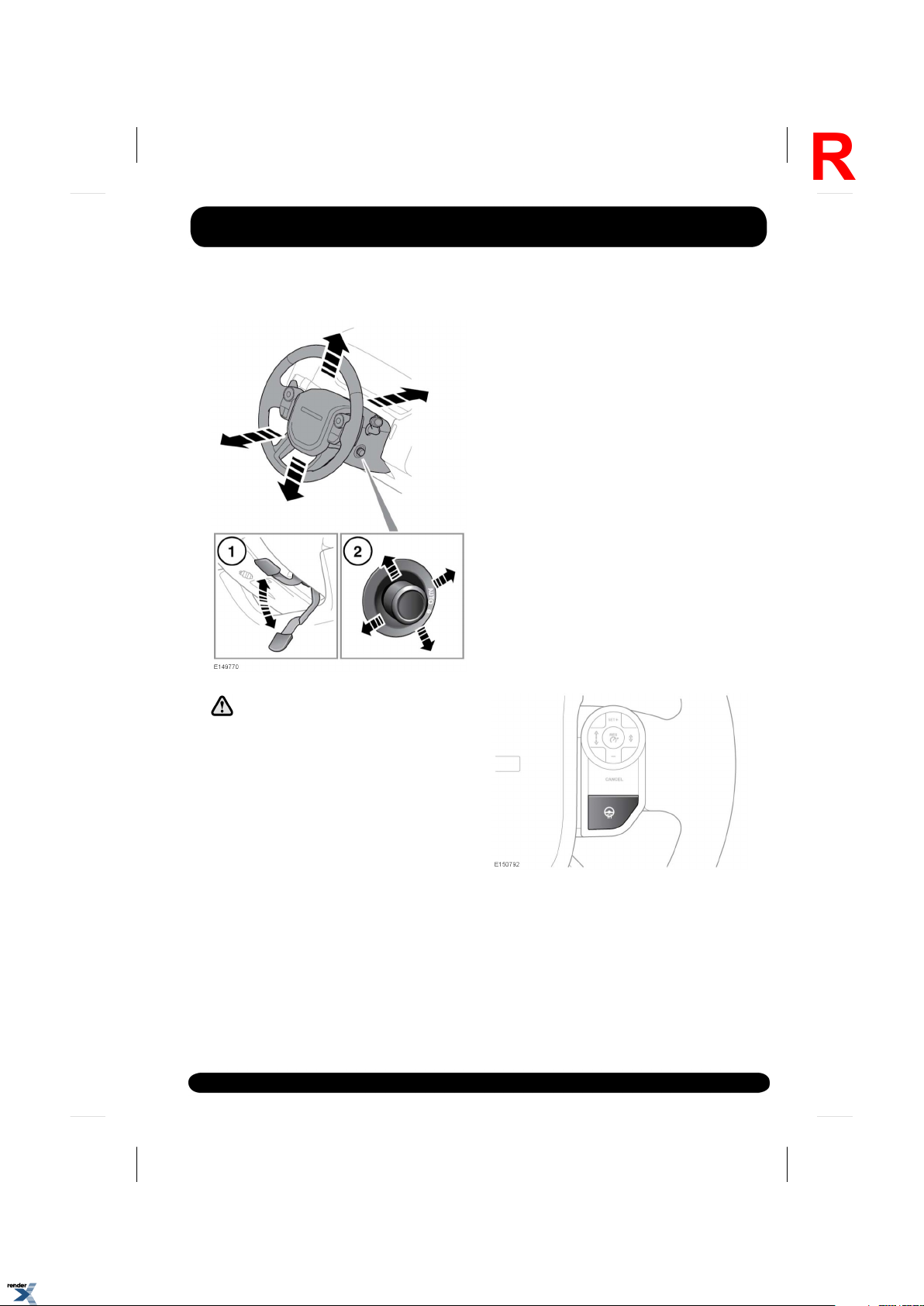
ADJUSTING THE STEERING WHEEL
Never adjust the steering column while
the vehicle is in motion.
1.
Manual adjustment: Move the locking lever
(located under the column) downwards to
unlock. Move the steering column up, down,
in or out, to the desired position.
Move the lever fully up to re-lock the
column.
2.
Electric adjustment: Move the control up
or down to adjust the tilt/height.
Move the control forwards or rearwards to
adjust reach.
ENTRY AND EXIT MODE
With the steering column control (2) in the
AUTO position, the steering column and driver’s
seat will move to provide easier entry and exit
from the vehicle.
On opening the driver’s door, the system will
raise the steering column to the highest position
and lower the driver’s seat to a lower position,
assisting with exit from the vehicle. When the
driver’s door is closed and the ignition turned
on, the system will return the driver’s seat and
steering column to the previous position.
Note: If the driver’s seat or steering column are
adjusted during entry or exit operation,
automatic movement will stop.
To prevent automatic movement of the driver’s
seat and steering column, turn the control
clockwise to the manual position.
Note: If the steering column switch is moved
away from AUTO when the driver’s seat and
steering column is in the exit position, the
driver’s seat and steering column will move
back to their previous positions when the
driver’s door is closed and the ignition is
switched on.
HEATED STEERING WHEEL
Press the button to turn the heating steering
wheel feature on and off. An amber indicator
will illuminate when the heated steering wheel
feature is on.
27
XML to PDF by RenderX XEP XSL-FO Formatter, visit us at http://www.renderx.com/
Page 28

Steering wheel
L
POWER STEERING
A fault with the power steering system is
indicated by a message in the Message centre,
accompanied by an amber warning lamp (see
49, GENERAL WARNING/INFORMATION
MESSAGE (AMBER)). A reduction in power
steering assistance may be experienced. The
fault may be caused by overheating due to
extensive steering inputs or high ambient
temperatures.
Full steering assistance should return when the
system has been allowed to cool. If full steering
assistance does not return, consult a Land
Rover Dealer/Authorised Repairer.
28
XML to PDF by RenderX XEP XSL-FO Formatter, visit us at http://www.renderx.com/
Page 29
Seat belts
R
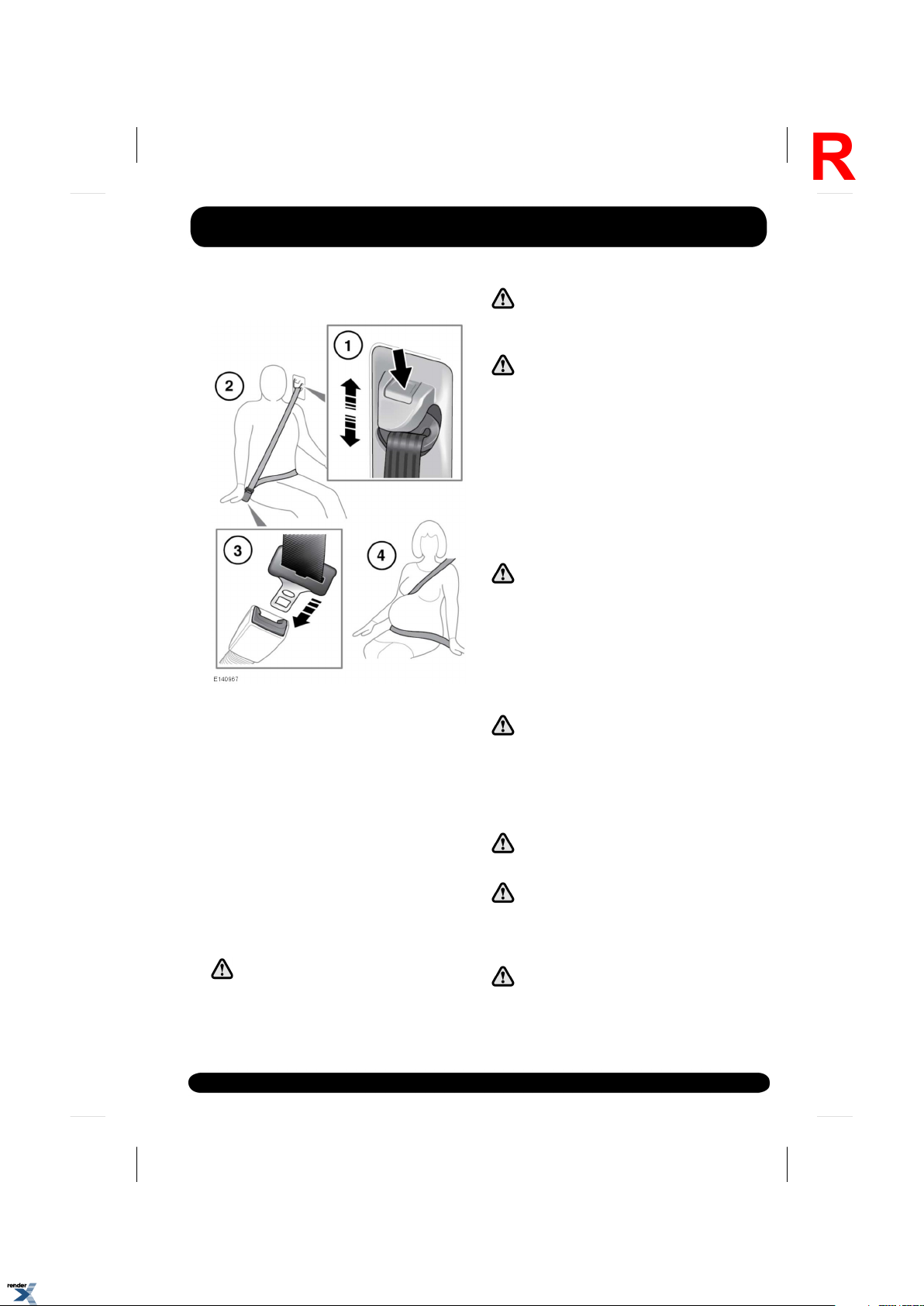
USING THE SEAT BELTS
1.
Seat belt height adjustment: Press to
release the catch.
With the catch depressed move the
mechanism slide up or down to the required
height. Make sure the locking mechanism
has engaged.
When correctly positioned the seat belt
should cross the collar bone at the
mid-point between the neck and end of your
shoulder.
Where possible, rear seat passengers
should adjust their position on the seat, to
enable the seat belt webbing to cross the
shoulder without pressing on the neck.
Make sure the height is correctly
adjusted and the mechanism is locked
in place before driving.
The use of comfort clips or devices that
would create slack in the seat belt
system is not advised.
WARNING: No modifications or
additions should be made by the user
which will either prevent the seat belt
adjusting devices from operating to
remove slack, or prevent the seat belt
assembly from being adjusted to
remove slack.
2.
Putting on a seat belt: Draw the belt out
smoothly, make sure the belt height, the
seat and the occupant's position on the
seat, are correct.
WARNING: Seatbelts are designed to
bear upon the bony structure of the
body, and should be worn low across
the front of the pelvis or the pelvis,
chest and shoulders, as applicable;
wearing the lap section of the belt
across the abdominal area must be
avoided.
Seatbelts should be adjusted as firmly
as possible, consistent with comfort,
to provide the protection for which they
have been designed. A slack belt will
greatly reduce the protection afforded
to the wearer.
Belts should not be worn with straps
twisted.
Each belt assembly must only be used
by one occupant; it is dangerous to put
a belt around a child being carried on
the occupant's lap.
The occupants of the front seats should
not travel with the seat back reclined
excessively. Doing so will reduce the
protection afforded by the seat belt.
29
XML to PDF by RenderX XEP XSL-FO Formatter, visit us at http://www.renderx.com/
Page 30
Seat belts
L
Never place anything between you and
the seat belt in an attempt to cushion
the impact in the event of an accident.
It can be dangerous, and will reduce
the effectiveness of the seat belt in
preventing injury.
3.
Fastening a seat belt: With the seat belt
correctly positioned, place the metal tongue
into the buckle nearest to you. Press it in
until a click is heard.
To release the seat belt, press the red
button.
Note: When releasing the seat belt it is
advisable to hold the belt before pressing
the release button. This will prevent the belt
from retracting too quickly.
4.
Seat belt use during pregnancy: Position
the lap strap comfortably across the hips
beneath the abdomen. Place the diagonal
part of the seat belt between the breasts
and to the side of the abdomen, as
illustrated. Make sure the seat belt is not
slack or twisted.
Position the seat belt correctly for the
safety of the mother and the unborn
child. Never wear just the lap strap and
never sit on the lap strap while using
just the shoulder strap. Both of these
actions are extremely dangerous and
may increase the risk of serious injury
in the event of an accident or during
emergency braking.
SEAT BELT SAFETY
Care should be taken to avoid
contamination of the webbing with
polishes, oils and chemicals, and
particularly battery acid. Cleaning may
safely be carried out using mild soap
and water.
The belt should be replaced if webbing
becomes frayed, contaminated or
damaged.
It is essential to replace the entire
assembly after it has been worn in a
severe impact even if damage to the
assembly is not obvious.
If any damage, wear, cuts, defects, or
impaired operation are noted with the
seat belts, the vehicle should be taken
to a Land Rover Dealer/Authorised
Repairer for immediate attention. Do
not use the vehicle if the seat belts
cannot be operated correctly.
Do not carry hard, fragile, or sharp
items between your person and the
seat belt.
Seat belts should be worn by all
vehicle occupants, for every journey
no matter how short.
Never wear just the lap belt or just the
shoulder belt of a lap/shoulder
diagonal seat belt. Both of these
actions are extremely dangerous and
may increase your risk of injury.
When using seat belts to restrain items
other than occupants, take care to
make sure the belts are not damaged,
or exposed to sharp edges.
SEAT BELT CHECKS
Note: If the vehicle is parked on an incline, the
seat belt mechanism may lock. This is not a
fault and the belt should be gently eased out
from the upper anchorage.
30
XML to PDF by RenderX XEP XSL-FO Formatter, visit us at http://www.renderx.com/
Page 31

Seat belts
R
The seat belts should be inspected regularly to
check for fraying, cuts, wear to the webbing and
the condition and security of the mechanism,
buckles, adjusters and mounting points.
• With the seat belt fastened, give the
webbing near the buckle a quick upward
pull. The buckle must remain securely
locked.
• With the seat belt unfastened, unreel the
seat belt to the limit of its travel. Check that
it unreels smoothly with no snatches or
snags. Allow the belt to fully retract, again
checking for smooth operation.
• Partially unreel the seat belt, then hold the
tongue plate and give a quick forward pull.
The mechanism must lock and prevent any
further unreeling.
If any of the seat belts fail to meet those criteria,
immediately contact your Dealer/Authorised
Repairer.
SEAT BELT PRE-TENSIONERS
The seat belt pre-tensioners activate in
conjunction with the Supplementary Restraint
System (SRS) to provide extra protection in the
event of a severe frontal impact.They
automatically reduce any slack in a seat belt to
reduce forward movement of a seat occupant.
The seat belt pre-tensioners will
activate only once and then must be
replaced. Failure to replace them will
reduce the effectiveness of the SRS in
reducing the risk of serious injury or
death in the event of an accident.
After any impact, have the seat belts
and pre-tensioners checked and if
necessary, replaced by a
Dealer/Authorised Repairer.
SEAT BELT REMINDER
Seat belt reminder commences when the vehicle
is in motion and the driver's belt is unbuckled.
Dependent on market, the warning indicator in
the Instrument panel illuminates (See 50, SEAT
BELT (RED)), and an audible chime sounds. The
visual and audible warnings applicable to the
Seat belt reminder feature are market dependent
to meet individual market requirements. The
warning signals given may also change
depending on whether the vehicle is stationary
or when the vehicle speed exceeds a predetermined threshold. In certain markets, the
Seat belt reminder feature also applies to the
front passenger seat.
The Message centre also displays a front and
rear seat belt reminder that warns the driver
when the seat belt of any occupied seat is not
fastened or is unfastened during a journey.
• Each seating position is represented by a
passenger icon, the colour and symbol of
which indicates the seat belt status:
• Tick - seat belt in the indicated position
is fastened.
• Cross - seat belt in the indicated
position has been unfastened while the
vehicle ignition is on. This indicator will
turn grey after 30 seconds.
• Grey - seat belt not fastened.
31
XML to PDF by RenderX XEP XSL-FO Formatter, visit us at http://www.renderx.com/
Page 32

Seat belts
L
Note: The indicators will be displayed for 30
seconds each time there is a status change, e.g.,
a seat belt is unfastened or fastened or a door
is opened and then closed.
• In addition, an audible warning will sound
under the following conditions:
• The seat belt of an occupied front seat
is not fastened or is unfastened during
a journey.
• A rear seat belt is unfastened.
Note: Objects placed on the front passenger
seat may activate the seat belt reminder warning
chime and indicator. It is recommended that
any objects placed on the front passenger seat
are secured using the seat belt.
32
XML to PDF by RenderX XEP XSL-FO Formatter, visit us at http://www.renderx.com/
Page 33

Child safety
R
CHILD SAFETY LOCKS
If children are to be carried in the rear seat
positions, it is recommended that the rear door
interior handles are disabled.
Press the switch to activate the child door locks
and inhibit the rear windows. The LED indicator
will illuminate when active and a message will
display in the Message centre.
To switch off, press the switch again. The LED
will extinguish and a message will display in the
Message centre.
CHILD SEATS
For optimum safety, children should
travel in the rear of the vehicle at all
times; front passenger seat travel is
not recommended. However, if it is
essential that a child travels in the
front (not permitted in Australia), set
the vehicle seat fully rearward and seat
the child in an approved forward-facing
child seat. Do not use a rear-facing
child seat - an inflating airbag could
impact with the seat and cause serious
injury.
Do not use a forward facing child seat
until the child using it is above the
minimum weight of 9 kg (20 lb.) and
able to sit up unaided. Up to the age
of 2, a child's spine and neck are not
sufficiently developed to avoid injury
in a frontal impact.
Do not allow a baby or infant to be held
or carried on the lap. The force of a
crash can increase effective body
weight by as much as thirty times,
making it impossible to hold onto the
child.
Children typically require the use of a
booster seat appropriate to their age
and size, thereby enabling the seat
belts to be properly fitted, reducing the
risk of injury in a crash. Children could
be endangered in a crash if their child
restraints are not properly secured in
the vehicle.
Do not use a child seat that hooks over
the seat back. This type of seat cannot
be satisfactorily secured and is unlikely
to be safe for your child.
NEVER use a rearward facing child
restraint on a seat protected by an
ACTIVE AIRBAG in front of it, DEATH or
SERIOUS INJURY to the CHILD can
occur.
The seat belts fitted to your vehicle are designed
for adults and larger children. For their safety
it is very important for all infants and children
under 12 years of age to be restrained in a
suitable child safety seat appropriate to their
age and size.
33
XML to PDF by RenderX XEP XSL-FO Formatter, visit us at http://www.renderx.com/
Page 34

Child safety
L
The following symbols warn against the use of
a rear-facing child seat in the front passenger
seat, when a front passenger airbag is fitted and
is operational.
Extreme Hazard! Do not use a rearward
facing child restraint on a seat
protected by an airbag in front of it!
This symbol is fixed to the end of the fascia on
the passenger side.
This symbol is fixed to the passenger side
sun-visor.
If it is essential that a child travels in the front
passenger seat (and national legislation permits
this), Land Rover recommends that the
following preparations are made before fitting
the child restraint.
• Disable the front passenger airbag.
• Adjust the front passenger seat fully
rearwards.
• Adjust the lumbar support to its minimum
support position.
• Adjust the seat cushion to its highest
position. If cushion rake adjustment is
possible, adjust it to its lowest position.
• Adjust the seat back to the upright position
to support the child restraint.
• Adjust the seat belt adjustable upper
anchorage to its lowest position.
CHILD RESTRAINT CHECK LIST
Every time a child travels in the vehicle observe
the following:-
• Carefully follow the instructions provided
by the manufacturer of the restraint system.
• Always use the appropriate child restraints
and adjust harnesses for every child, every
trip.
• Adjust the harnesses for every child on
every trip.
• Make sure all slack is removed from the
adult seat belt.
• Always attach the top tether when installing
an ISOFIX seat.
• Always check the security of the child
restraint.
• Do not dress a child in bulky clothing, or
place any objects/padding between the child
and the restraint.
• Regularly check the fit and condition of child
restraints. If the fit is poor, or wear/ damage
is visible replace the restraint immediately.
• Set a good example - always wear your seat
belt.
• On child seats fitted with a support leg
adjust the leg so that it rests firmly onto the
floor.
34
XML to PDF by RenderX XEP XSL-FO Formatter, visit us at http://www.renderx.com/
Page 35

Child safety
R
• For some child seats it may be necessary
to remove the head restraint to ensure a
stable fit. Always refit a removed head
restraint after the child seat is removed. See
25, HEAD RESTRAINT REMOVAL.
child restraint anchorages are
designed to withstand only those loads
imposed by correctly fitted child
restraints. Under no circumstances are
they to be used for adult seat belts,
harnesses or for attaching other items
or equipment to the vehicle.
CHILD SEAT POSITIONING
Information given within the table is
correct at the time of going to press.
However, availability of child restraints
may change. Please consult your
Dealer/Authorised Repairer for the latest
recommendation.
Mass group.
Seating positions
0 = Up to
10 kg (22 lb)
0-9 months
0+ = Up to
13 kg (29 lb)
0-18 months
Note: The information contained in the following
table may not be applicable to all countries. If
you are in any doubt regarding the type and
fitment of child seats seek advice from your
Dealer/Authorised Repairer.
Crash statistics show that children are
safest when properly restrained in a
child or infant restraint system that is
secured in a rear seating position.
Note: Ages given are approximate. In case of
doubt, the child’s weight, not age, should be
used when considering an appropriate child
seat.
Note: The legislation which governs how and
where children should be carried when travelling
in a vehicle, is subject to change. It is the
responsibility of the driver to comply with all
regulations in force.
I = 9-18 kg
(20-40 lb) 9
months to
4 years
II = 15-25 kg
(33-55 lb) 4-9
years
III = 25-36 kg
(55-80 lb) 8-
12 years
UUUUUFront passenger*
UUUUURear seats
XXXXXThird row seats
• U = Suitable for universal category
restraints approved for this mass group.
• UF = Suitable for Forward-facing universal
category restraints approved for this mass
group.
• X = not suitable for children in this mass
group.
XML to PDF by RenderX XEP XSL-FO Formatter, visit us at http://www.renderx.com/
* Always make sure the passenger airbag has
been disabled before using a child restraint in
this seating position. Adjust the seat back to the
upright position to support the child restraint.
If the head restraint has been removed, make
sure it is refitted before the seat is used by a
passenger.
35
Page 36

Child safety
L
RECOMMENDED CHILD SEATS
Recommended seatChild size/age
Groups 0 and 0+
Britax/Römer Baby Safe
Plus
Britax/Römer Duo PlusGroup I
Britax/Römer Kid PlusGroup II and III
36
XML to PDF by RenderX XEP XSL-FO Formatter, visit us at http://www.renderx.com/
Page 37

ISOFIX ANCHOR POINTS
R
Child safety
Both of the outer seat positions on the rear,
second row seat are equipped to accept ISOFIX
restraints.
This symbol is shown on a label
sewn into the seats to indicate the
position of the ISOFIX lower
anchorages.
To install an ISOFIX child seat:-
1.
Raise or remove the head restraint.
2.
ISOFIX anchor points are in the fold of the
seats.
3.
Slide the child seat locking mechanism into
the anchor point.
4.
Upper tether anchorages are provided on
the rear of the second row, 2 outer seats.
5.
Hook the tether to the tether anchorage and
tighten to secure.
Note: Always make sure if an upper tether is
provided, it is fitted and tightened correctly.
Test the security of the child restraint. To do
this, attempt to pull the restraint away from the
vehicle seat and twist the restraint from side to
side. Even if the restraint appears secure, you
should still check the anchor points visually, to
make sure correct attachment.
Do not attempt to fit ISOFIX restraints
to the rear, second row centre seating
position. The anchor bars are not
designed to hold an ISOFIX restraint in
this position.
If the restraint is not correctly
anchored, there is a significant risk of
injury to the child in the event of a
collision or emergency braking.
Note: Always refit a removed head restraint after
the child restraint is removed. See 25, HEAD
RESTRAINT REMOVAL.
37
XML to PDF by RenderX XEP XSL-FO Formatter, visit us at http://www.renderx.com/
Page 38

Child safety
L
ISOFIX child seat positions
I = 9 to 18 kg (20 to 40 lb) 9 months - 4 years
• IUF = Suitable for ISOFIX forward child
restraint systems of universal category
approved for use in the mass group.
• IL = These ISOFIX child restraint systems
are of the specific vehicle, restricted or
semi-universal categories.
• X = Not suitable for ISOFIX child restraint
fitment in this mass group.
• * = Child seat suitable for use in these
locations, is the Britax/Römer Baby Safe
Plus ISOFIX.
Note: Ages given are approximate. In case of
doubt, the child’s weight not age should be used
when considering an appropriate child seat.
Note: The information contained in the table
may not be applicable to all countries. If you
are in any doubt regarding the type and fitment
of child seats seek advice from your
Dealer/Authorised Repairer.
Note: ISOFIX anchorages are provided for the
rear, second row outer seating positions. ISOFIX
child restraints should be securely attached
following the manufacturers instructions at
these locations only.
FixturesSize classesMass group as shown on child restraint
C/D
A/B1/B
Note: A tether anchorage is provided for the
rear, second row centre seat position. Do not
use this anchor position with an ISOFIX child
seat.
ISO R2/R3
ISO F2/F2X/F3
Rear outboard
seats
XISO L1/L2F/GCarrycot
IL*ISO R1E0 = Up to 10 kg (22 lb) 0-9 months
IL*ISO R1/R2/R3C/D/E0+ = Up to 13 kg (29 lb) 0-18 months
X
IUF
N/AN/AN/AII = 15 to 25 kg (33 to 55 lb) 4-9 years
N/AN/AN/AIII = 22 to 36 kg (49 to 80 lb) 8-12 years
INSTALLING TETHER ANCHORAGE CHILD RESTRAINTS
Child restraint anchorages are
designed to withstand only those loads
imposed by correctly fitted child
restraints. Under no circumstances are
they to be used for adult seat belts,
harnesses or for attaching other items
or equipment to the vehicle.
Always follow the child seat or restraint
system manufacturer’s instructions
when fitting tether straps.
When fitting a child seat or restraint
system, always pass the tether strap
over the top of the seat back and
beneath the head restraint.
If a child seat or restraint system is to
be fitted to the centre seating position,
the centre armrest must be in the
stowed position (folded into the seat).
38
XML to PDF by RenderX XEP XSL-FO Formatter, visit us at http://www.renderx.com/
Page 39

Your vehicle is equipped with anchorage points
R
on the back of the second row seat frames.
These should be used to attach straps from
child seats or restraint systems.
• Install the child restraint securely in 1 of the
rear seating positions.
• Pass the tether strap over the seat back and
beneath the head restraint for the outer seat
positions.
Note: For the centre seat position, pass the
tether strap over the fixed head restraint.
• Attach the tether strap hook to the tether
anchor point on the back of the seat. Ensure
that the tether strap hook is facing the
correct way (see illustration).
• Tighten the tether strap according to the
child restraint manufacturer's instructions.
Child safety
BOOSTER SEATS
In a situation where a child is too large to fit
into a child safety seat but is still too small to
safely use just the 3 point belt, a booster seat
is recommended for maximum safety. Follow
the manufacturer's instructions for fitting and
use, then adjust the seat belt to suit. See 35,
CHILD SEAT POSITIONING.
The vehicle head restraint may need to be
removed to accommodate all adjustments of
the child restraint. See 25, HEAD RESTRAINT
REMOVAL.
39
XML to PDF by RenderX XEP XSL-FO Formatter, visit us at http://www.renderx.com/
Page 40

Airbags
L
AIRBAGS
1.
Passenger front airbag.
2.
Curtain airbag.
3.
Side airbags.
4.
Driver’s front airbag.
Note: The general location of airbags fitted to
the vehicle are marked by the word AIRBAG.
Always contact your Dealer/Authorised Repairer
if:
• An airbag inflates.
• The front or sides of the vehicle are
damaged.
• Any part of the airbag system shows signs
of cracking or damage, including trim
covering airbags.
40
AIRBAG OPERATION
For the airbags to operate correctly the
roof lining and door post trims must be
in good condition, correctly fitted, and
free from obstruction. Any damage,
wear, or incorrect fitment should be
referred to your Dealer/ Authorised
Repairer as soon as possible for
examination and repair.
XML to PDF by RenderX XEP XSL-FO Formatter, visit us at http://www.renderx.com/
Page 41

Airbags
R
Do not allow passengers to obstruct
the operation of the airbags by placing
any part of their person, or any objects,
in contact with, or close to, an airbag
module. Only use approved
accessories (e.g. seat covers).
Make sure a gap is maintained
between the side of the vehicle, and
the head and torso. This will enable
unobstructed inflation of the curtain,
and seat mounted side airbags.
Airbags inflate at high speeds. To
minimise the risk of injury, make sure
all vehicle occupants wear correctly
positioned seat belts, sit correctly in
the seats, and position the seats as far
back as practical.
Airbag inflation takes place
instantaneously, and cannot protect
against the effects of secondary
impacts. Under these circumstances
the only protection will be provided by
a correctly worn seat belt.
Phone systems should only be installed
by qualified persons familiar with the
operation of, and requirements for,
vehicles fitted with SRS. If you are in
any doubt, seek advice from your
Dealer/Authorised repairer.
Airbag deployment is dependent on the rate at
which the passenger compartment changes
velocity during a collision. Circumstances
affecting different collisions (vehicle speed,
angle of impact, type and size of object hit, etc.),
vary considerably and will affect the rate of
deceleration accordingly.
Airbags cannot deploy correctly if they are
obstructed. Examples of obstructions are:
• Any part of an occupants body in contact
with, or close to, an airbag cover.
• Objects placed on, or close to, an airbag
cover.
• Clothing, sun screens, or other material
hanging from grab handles.
• Clothing, cushions, or other material,
covering seat mounted airbags.
• Seat covers which are not approved by Land
Rover, or specifically designed for use with
seat mounted airbags.
This list is not exhaustive, and it remains the
responsibility of the driver and passengers to
make sure the airbags are not obstructed in any
way.
The airbags and SRS are not designed to
operate as a result of:
• Rear impacts.
• Minor front impacts.
• Minor side impacts.
• Heavy braking.
• Driving over bumps and pot holes.
High speed impacts may cause serious
injury or death irrespective of safety
features fitted to a vehicle.
The airbags and SRS cannot provide
protection in some types of impact.
Under these circumstances the only
protection will be provided by a
correctly worn seat belt.
41
XML to PDF by RenderX XEP XSL-FO Formatter, visit us at http://www.renderx.com/
Page 42

Airbags
L
FRONT AIRBAGS
The front passenger and driver airbags have 2
levels of deployment, depending on the severity
of the frontal impact. In a severe impact, the air
bags inflate fully to offer maximum protection.
In a lesser impact, full deployment is not
required, so the airbags are inflated to a reduced
pressure.
SIDE AND CURTAIN AIRBAGS
The seat mounted side airbags are designed to
protect the thorax region of the torso and will
deploy only in the event of a side impact and
then, only on the side of the impact.
Both sides will deploy in the event of a rollover.
The curtain airbags are deployed in side impact
and rollover events, providing greater protection
from serious head injuries. They deflate at a
slower rate than the front or side air bags.
AIRBAG DEPLOYMENT EFFECTS
When an airbag inflates, a fine powder
is released. This is normal and not an
indication of a malfunction. The
powder may cause irritation to the skin
and should be thoroughly flushed from
eyes and any cuts or abrasions.
Airbag deployment is accompanied by
a very loud noise which may cause
discomfort and temporary loss of
hearing.
Airbags inflate at high speed and can
cause injuries. To minimise the risk of
injury, make sure all occupants wear
correctly positioned seat belts, sit
correctly in the seats and position the
seats as far back as is practicable.
After inflation, some airbag
components will be very hot. Do not
touch the airbag components until they
have cooled sufficiently.
AIRBAG WARNING LAMP
If the warning lamp indicates that a
fault is present in the system, do not
use a child restraint on the front
passenger seat.
If any of the following warning lamp conditions
occur, the vehicle should be checked by your
Dealer/Authorised Repairer immediately.
• The warning lamp fails to illuminate when
the ignition is turned on.
• The warning lamp fails to extinguish after
8 seconds of the ignition being turned on.
• The warning lamp illuminates at any time,
other than the bulb check, when the ignition
is turned on.
When the ignition is switched on, a diagnostic
control unit monitors the readiness of the
system’s electrical circuits. The elements of the
Supplementary Restraint System (SRS) being
monitored include:
• SRS warning indicator.
• Rotary coupler.
• Airbag modules.
• Seat belt pre-tensioners (front and 2nd row
rear seat belts).
• Front seat belt buckle switches.
• Airbag diagnostic control unit.
• Crash and rollover sensors.
• Airbag wiring harnesses.
DISABLING THE PASSENGER AIRBAG
Note: Disabling the passenger airbag is market
dependent.
42
XML to PDF by RenderX XEP XSL-FO Formatter, visit us at http://www.renderx.com/
Page 43

The passenger front airbag can be switched on
R
and off using the interactive controls on the
Instrument panel when the vehicle is stationary.
See 46, INSTRUMENT PANEL MENU
The passenger airbag should be
disabled only when a child restraint is
fitted to the front passenger seat.
Crash test data and statistics show that
the safest place for a child to be
restrained is in a child seat correctly
fitted to the vehicle's rear seat.
Do not use a child restraint on a seat
protected by an operational airbag in
front of it. Doing so presents a high risk
of death or serious injury to the child
in the event of an accident.
Select Passenger Airbag from the Vehicle
Setup menu, located in the Main Menu.
The displayed text and diagram will show the
current Passenger Airbag On or Off status.
Select Change Setting to choose either On or
Off.
A warning lamp in the roof console will
illuminate if Passenger Airbag Off setting is
selected.
Note: The Instrument panel will also display a
warning for 4 seconds every time the ignition
is switched on.
Airbags
As soon as the child seat is removed
from the front passenger seat, the
airbag must be turned on. Failure to
do so, will put any front seat
passengers at greater risk of death or
serious injury in the event of an
accident.
When checking the operational status
of the front passenger airbag, make
sure the ignition is switched on.
Do not fit a child restraint to the front
passenger seat if the SRS warning light
illuminates continuously with the
ignition on.
AIRBAG SERVICE INFORMATION
Do not attempt to service, repair,
replace, modify, or tamper with, any
part of the SRS. This includes wiring
or components in the vicinity of SRS
components. Doing so may cause the
system to trigger, or render the system
inoperative.
43
XML to PDF by RenderX XEP XSL-FO Formatter, visit us at http://www.renderx.com/
Page 44

Airbags
L
Do not use any electrical test
equipment or devices in the vicinity of
SRS components or wiring. Doing so
may cause the system to trigger, or
render the system inoperative.
All of the following operations should only be
carried out by a Dealer/Authorised Repairer, or
suitably qualified person:
• Removal or repair of any wiring or
component in the vicinity of any SRS
components.
• Installation of electrical, or electronic,
equipment and accessories.
• Modification to the front or sides of the
vehicle exterior.
• Attachment of accessories to the front or
sides of the vehicle.
DISABILITY MODIFICATIONS
Occupants with disabilities which may require
modification of the vehicle, must contact a
Dealer/Authorised Repairer before any
modifications are made.
44
XML to PDF by RenderX XEP XSL-FO Formatter, visit us at http://www.renderx.com/
Page 45

INSTRUMENT PANEL
R
Instrument panel
7.
Fuel gauge.
If the amber low fuel warning lamp
illuminates, the vehicle should be refuelled
as soon as possible. The approximate
distance that can be travelled on the
remaining fuel can be viewed via the trip
computer Distance to Empty function. See
47, TRIP COMPUTER.
As a reminder for the location of the fuel
filler, there is an arrow next to the fuel pump
symbol pointing to the relevant side of the
vehicle.
If the temperature gauge pointer moves into
the red section at the top of the scale, the
engine is overheating. Stop the vehicle as
soon as safety permits and allow the engine
to idle until the temperature reduces. If the
temperature does not reduce after several
minutes, switch off the engine and allow to
cool. If the problem persists, seek qualified
assistance immediately.
Never allow the engine to run out of fuel.
The resultant misfire can seriously
damage the catalytic convertor.
1.
Tachometer.
2.
Message centre.
3.
Speedometer.
4.
Temperature gauge.
5.
Gear selector position display.
6.
Total distance (odometer) and trip recorder.
Serious engine damage can occur if the
vehicle is driven while the engine is
overheating.
Note: If engine overheating occurs, there
may be a noticeable reduction in engine
power and the air conditioning may cease
operation. This is a normal operating
strategy, to reduce load on the engine and
assist with cooling.
45
XML to PDF by RenderX XEP XSL-FO Formatter, visit us at http://www.renderx.com/
Page 46

Instrument panel
L
INSTRUMENT PANEL MENU
To display and navigate through the instrument
panel menu, operate the menu control on the
steering wheel.
1.
Steering wheel menu control.
2.
Close and return to Main Menu.
3.
Access the vehicle Driving Features menu.
4.
Access the Trip Computer menu.
5.
Access the Instrument Display menu.
6.
Access the Vehicle Set-Up menu.
7.
Access the Vehicle Info menu.
Note: Only available before the engine
starts.
Digital Speedometer
A digital speedometer is available in some
markets. Depending on market specification,
the driver may choose to turn the digital
speedometer on or off, or change the units from
imperial to metric. The digital speedometer can
be accessed through the Digital speedometer
option in the instrument panel menu.
WARNING AND INFORMATION MESSAGES
A number of vehicle features and display
settings may be configured via the instrument
panel menu.
46
Do not ignore warning messages, take
appropriate action as soon as possible.
Failure to do so may result in serious
damage to the vehicle.
For information regarding the individual
messages, their meanings, and any action
required, please refer to the relevant section
within this handbook.
If more than 1 message is active, each is
displayed in turn for 2 seconds in order of
priority.
Note: Messages are displayed in order of
importance. High importance warning messages
are given the highest priority.
XML to PDF by RenderX XEP XSL-FO Formatter, visit us at http://www.renderx.com/
Page 47

Instrument panel
R
Warning messages may be accompanied by an
audible warning, and the message text may have
the handbook symbol next to it. Warning
messages are displayed until the condition
causing the fault is rectified or the message is
suppressed using the OK button on the steering
wheel. If a message is suppressed, an amber
or red warning icon will remain illuminated until
the cause of the message is rectified.
TRIP COMPUTER
The computer memory stores data for a journey
or series of journeys until it is reset to zero.
There are 3 trip memories available, A, B and
Auto. You can specify which trip memory is
viewable using the Instrument panel menu.
USING THE TRIP COMPUTER
The trip computer displays the date and
odometer reading. A short press (1 second or
less) or a series of short presses of the ¡ button
will change the trip computer display. The
options available are:
• Trip distance.
• Trip average speed.
• Trip average fuel consumption.
• Instantaneous (short term average) fuel
consumption.
• Driving style.
• Range available from remaining fuel.
• Blank display.
To reset the trip computer values to zero, press
and hold the i button for 2 seconds.
The trip options can be configured using the
Trip content feature within the Trip computer
menu.
To reset the fuel consumption value, press and
hold the i button until the display clears.
The distance, average speed and average fuel
economy values for trip A and trip B can be
reset. Set the trip computer display to show the
trip that you wish to reset, then press and hold
the ¡ button until the message resetting trip is
displayed.
It is not possible to manually reset the Auto trip
memory. This resets automatically each time
the ignition is switched on.
Trips may be added together, to record a
continuous journey, or removed. Press the i
button for longer than 1 second, when Auto trip
memory values for distance, average speed and
average fuel economy are displayed, then
adding last journey or removing last journey
will appear on the screen. Press the i button for
longer than 1 second, and the previous trip
information will be added to or removed from
the current trip and the new total will be
displayed. There is no limit to the number of
times this can be done before the ignition is
switched off.
TRIP DISTANCE
Distance travelled since the last memory reset.
The maximum trip reading is 9999.9 (kilometres
or miles). The computer will automatically reset
to zero if this distance is exceeded.
47
XML to PDF by RenderX XEP XSL-FO Formatter, visit us at http://www.renderx.com/
Page 48

Instrument panel
L
RANGE
This shows the predicted distance (kilometres
or miles) that the vehicle should travel on the
remaining fuel, assuming fuel consumption and
driving style remain constant.
METRIC/IMPERIAL/MIXED DISPLAY
The trip computer readings can be changed
between metric, imperial and mixed units in the
Trip Computer menu of the Message centre.
See 46, INSTRUMENT PANEL MENU.
Note: Temperature display can be changed
between °C (Celsius) and °F (Fahrenheit)
independently of Metric or Imperial units.
SERVICE INTERVAL INDICATOR
An upcoming service interval will be notified to
the driver via the Message centre, as either a
distance or time left until service is due. Once
the distance or time are exceeded, the display
will show a negative value (-) to indicate that a
service is overdue.
One or both types of service interval (distance
and time) may be displayed.
48
XML to PDF by RenderX XEP XSL-FO Formatter, visit us at http://www.renderx.com/
Page 49

Warning lamps
R
WARNING LAMPS AND INDICATORS
RED warning lamps are for primary warnings.
A primary warning must be investigated
immediately by the driver or qualified assistance
before continuing.
AMBER and YELLOW warning lamps are for
secondary warnings. Some indicate that a
vehicle system is in operation, others indicate
that the driver must take action and then seek
qualified assistance as soon as possible.
GREEN and BLUE lamps within the instrument
panel indicate system status.
LAMP CHECK
A warning lamp bulb check is initiated when the
ignition system is switched on and lasts for 3
seconds (except for the airbag warning lamp
which will remain on for 6 seconds). If any
warning lamp remains on after this period,
investigate the cause before driving.
Some warning lamps have associated messages
displayed on the Message centre.
Note: Not all warning lamps are included in the
check (e.g. high beam headlamps and direction
indicators).
Note: If a trailer with LED lights is connected to
the trailer socket, the bulb check may not be
performed.
CRITICAL WARNING MESSAGE (RED)
Illuminates when a critical warning
message is available in the Message
centre.
GENERAL WARNING/INFORMATION MESSAGE (AMBER)
Illuminates when a non-critical
warning message or an information
message is available in the Message
centre.
ENGINE TEMPERATURE (RED)
Illuminates when the engine
temperature is too high. The
Message centre will also display the
message ENGINE OVERHEATING.
Stop the vehicle as soon as safety permits and
seek qualified assistance before continuing.
LOW OIL PRESSURE (RED)
If the lamp flashes or illuminates
while driving, stop the vehicle as
soon as safety permits and switch
off the engine immediately.
Check and top-up the oil level if necessary. Start
the engine, if the lamp remains illuminated,
switch the engine off immediately and seek
qualified assistance before continuing.
BRAKE (RED)
Illuminates briefly as a bulb check
when the ignition is switched on.
If the lamp illuminates while driving, suspect
low brake fluid level or a fault with the Electronic
Brake Distribution (EBD) system.
Stop the vehicle as soon as safety permits and
check and top-up the brake fluid, if necessary.
If the lamp remains illuminated, seek qualified
assistance before continuing.
49
XML to PDF by RenderX XEP XSL-FO Formatter, visit us at http://www.renderx.com/
Page 50

Warning lamps
L
PARKING BRAKE (RED)
Illuminates when the parking brake
is correctly applied. If the lamp
flashes, a fault has been detected.
Seek qualified assistance urgently.
BATTERY CHARGE (RED)
Illuminates as a bulb check when
the ignition is switched on and
extinguishes when the engine is
started.
If the lamp remains on or illuminates while
driving, there is a fault with the battery charging
system. Seek qualified assistance urgently.
SEAT BELT (RED)
Illuminates, accompanied by a
chime, when the vehicle is in motion
and an occupied front seat belt is
unbuckled.
The lamp will extinguish when the relevant seat
belt is buckled.
Note: Objects on the front passenger seat may
activate the seat belt reminder. It is
recommended that any objects placed on the
front passenger seat are secured using the seat
belt. See 29, USING THE SEAT BELTS.
ENGINE/TRANSMISSION (AMBER)
Illuminates briefly as a bulb check
when the ignition is switched on.
If the lamp illuminates when the engine is
running, there is an emissions related fault with
the engine or transmission. The vehicle can be
driven but may enter limp-home mode with the
possibility of reduced performance. Seek
qualified assistance as soon as possible.
If the warning lamp flashes while the engine is
running, reduce speed and seek qualified
assistance urgently.
GLOW PLUGS (AMBER)
Illuminates when the ignition is
switched on to indicate that the glow
plugs are active.
BRAKE (AMBER)
Illuminates briefly as a bulb check
when the ignition is switched on.
If the lamp illuminates after starting the engine
or while driving, suspect worn brake pads or a
fault with the Emergency Brake Assist (EBA)
system.
The vehicle can still be driven with care, but
seek qualified assistance urgently.
DYNAMIC STABILITY CONTROL (DSC) (AMBER)
Flashes when DSC is active.
If there is a fault, it will remain illuminated and
the Message centre will display DSC NOT
AVAILABLE. The vehicle can still be driven, but
without DSC assistance. Seek qualified
assistance as soon as possible.
DYNAMIC STABILITY CONTROL (DSC) OFF (AMBER)
Illuminates when DSC is switched
off. A chime will sound and a
confirmation message will be
displayed in the Message centre.
50
XML to PDF by RenderX XEP XSL-FO Formatter, visit us at http://www.renderx.com/
Page 51

Warning lamps
R
ANTI-LOCK BRAKING SYSTEM (ABS) (AMBER)
Illuminates briefly as a bulb check
when the ignition is switched on.
If the lamp remains on or illuminates while
driving, there is a fault with the ABS system.
Drive with care, avoiding heavy brake
application and seek qualified assistance
urgently.
AIRBAG (AMBER)
Illuminates as a bulb check when
the ignition is switched on and
extinguishes when the engine is
started.
If the lamp illuminates when driving, there is a
fault with the airbag system. Seek qualified
assistance as soon as possible.
ADAPTIVE FRONT LIGHTING SYSTEM (AMBER)
Illuminates when there is a system
fault. The headlamps will still
operate, but without this feature
operating correctly. Seek qualified
assistance as soon as possible.
REAR FOG LAMP (AMBER)
Illuminates when the rear fog lamps
are switched on.
AUTOMATIC SPEED LIMITER (AMBER)
Illuminates when Automatic Speed
Limiter is active.
FOLLOW MODE (AMBER)
Illuminates when the Adaptive cruise
control system is in follow mode.
EXTERNAL TEMPERATURE (AMBER)
Illuminates when the external
temperature is low enough that ice
may be present on the road.
TYRE PRESSURE MONITORING SYSTEM (YELLOW)
The warning lamp illuminates,
accompanied by a message in the
Message centre, to warn that 1 or
more tyres are significantly underinflated.
Stop the vehicle as soon as possible, check the
tyre pressures and inflate to the recommended
pressure.
The lamp will flash to indicate a system fault.
HIGH BEAM (BLUE)
Illuminates when the high beam
headlamps are switched on or
flashed.
LOW FUEL WARNING (AMBER)
Illuminates when the fuel level is
low. Refuel at the earliest
opportunity.
The arrow shows which side of the vehicle to
locate the fuel filler cap.
XML to PDF by RenderX XEP XSL-FO Formatter, visit us at http://www.renderx.com/
FRONT FOG LAMPS (GREEN)
Illuminates when the front fog lamps
are switched on.
51
Page 52

Warning lamps
L
SIDE LAMPS (GREEN)
Illuminates when the side lights are
switched on.
HIGH BEAM ASSIST (GREEN)
Illuminates when the auto high beam
feature has switched on the high
beams.
DIRECTION INDICATORS (GREEN)
The appropriate warning lamp will
flash when the direction indicators
are operated.
INTELLIGENT STOP/START (GREEN)
Illuminates when the engine is shut
down by the Eco Stop/Start system.
Note: Other warnings normally associated with
an engine shutdown, for example the ignition
warning lamp, do not illuminate during an
engine shutdown by the Eco Stop/Start system.
GEAR SHIFT (GREEN)
The gear shift indicator illuminates
briefly at the recommended gear
change point (upshift).
The shift indicator will not illuminate whilst
Cruise control is active and not being overridden
by pressing the throttle pedal.
Note: This warning indicator is only a guide. It
remains the responsibility of the driver to
operate the vehicle in an appropriate manner
for the prevailing conditions.
HILL DESCENT CONTROL (GREEN)
Illuminates continuously when HDC
is selected and HDC operating
conditions are met. See 135, HDC
CONTROLS.
If the lamp flashes, HDC has been selected, but
the operating conditions are not being met or
HDC fade-out is occurring.
LOW RANGE (GREEN)
Illuminates when Low range has
been selected.
CRUISE CONTROL (GREEN)
Illuminates when cruise control or
Adaptive cruise control is active.
FORWARD ALERT (GREEN)
Illuminates when Forward alert is
active.
TRAILER DIRECTION INDICATORS (GREEN)
Illuminates as a bulb check when
the ignition is switched on and
extinguishes when the engine is
started.
If a trailer is attached, the warning lamp will
flash in conjunction with the direction indicator
warning lamp. If the lamp fails to flash, the
direction indicator bulb on the trailer may be
faulty.
Note: If a trailer with LED lights is connected to
the trailer socket, the bulb check may not be
performed.
52
XML to PDF by RenderX XEP XSL-FO Formatter, visit us at http://www.renderx.com/
Page 53

LIGHTING CONTROL
R
Exterior lights
1.
With the headlamps on, push the control
away from the steering wheel to select high
beam. The warning lamp will illuminate. See
51, HIGH BEAM (BLUE).
Note: Do not use high beam where it may
distract or dazzle other road users.
2.
Pull the control towards the steering wheel
and release to flash the high beam on and
off. The high beam will remain on for as
long as the switch is held.
3.
Side lights.
4.
Headlamps.
5.
AUTO. With Auto lamps selected, when
ambient light fades and the ignition is on,
the side lights, tail lamps, low beam
headlamps and licence plate lamps will
switch on automatically. Headlamp courtesy
delay, High beam assist and Windscreen
wiper detection may also be activated.
Note: Low ambient light levels, caused by
adverse weather conditions, may also cause
Auto lamps to activate.
6.
Front fog lamps. Operates only while side
lights, headlamps or Auto lamps are
selected. Turn the collar away from the
steering wheel and release. The warning
lamp will illuminate. See 51, FRONT FOG
LAMPS (GREEN).
7.
Rear fog lamps. Operates only while side
lights, headlamps or Auto lamps are
selected. Turn the collar towards the
steering wheel and release. The warning
lamp will illuminate. See 51, REAR FOG
LAMP (AMBER).
DAYTIME RUNNING LAMPS
With the lighting control in the OFF position,
Daytime running lamps will switch on
automatically under the following conditions:
• The engine is running.
• The gear selector is out of park.
• The parking brake is not applied (is
released) - market dependent.
53
XML to PDF by RenderX XEP XSL-FO Formatter, visit us at http://www.renderx.com/
Page 54

Exterior lights
L
Unless required or prohibited by law,
daytime running lamps can be
disabled or enabled by a Land Rover
Dealer/Authorised Repairer.
HEADLAMP COURTESY DELAY
This feature operates whenever the headlamp
control is left in the AUTO position and the
ignition is turned off. The headlamps will remain
illuminated for up to 240 seconds.
Note: The time delay may be changed via the
Vehicle Set-Up menu (see 46, INSTRUMENT
PANEL MENU).
HIGH BEAM ASSIST
This feature automatically selects and deselects
high beam, under specific conditions of road
lighting and in the absence of other vehicle’s
lights. The system is only active when the
ambient light drops below a predetermined
level.
Note: It is not recommended that High beam
assist is used while driving off road.
See 52, HIGH BEAM ASSIST (GREEN).
For High beam assist to become operational,
the lighting control must be in the AUTO
position, with low beam headlamps selected.
See 53, LIGHTING CONTROL.
The system will only activate when the vehicle
speed exceeds 40 km/h (25 mph). The system
will deactivate when vehicle speed drops below
24 km/h (15 mph).
To manually select high beam, move the stalk
to the high beam position as normal. To return
to High beam assist, move the stalk back to the
central position.
To manually override to low beam from high
beam, pull the stalk to the flash position and
High beam assist will be cancelled. To return to
High beam assist, push the stalk to the high
beam position and then return it to the central
position.
To turn off High beam assist, turn the lighting
control from AUTO to headlamps on.
This feature can be disabled/enabled using the
Vehicle Set-Up menu (see 46, INSTRUMENT
PANEL MENU).
The following may affect the operation of High
beam assist:
• Highly reflective road signs.
• Dimly lit road users, for example cyclists or
pedestrians.
• Adverse weather conditions, for example
rain or fog.
• Dirty or obscured sensor.
• Dirty, damaged, or misted windscreen.
• Oncoming vehicles partially obscured by a
central highway barrier.
Note: The system cannot be relied upon to
activate or de-activate high beam in all possible
circumstances. It remains the driver’s
responsibility to make sure correct use of the
headlamps at all times.
Note: Make sure the sensor on the back of the
rear view mirror is not blocked or obstructed.
ADAPTIVE FRONT LIGHTING SYSTEM (AFS)
When cornering using dipped beam, AFS will
adjust the headlamp beams to provide improved
illumination in the direction of travel.
AFS is deactivated when:-
• Reverse gear is selected.
• The vehicle is stationary.
• Daytime running lamps are on.
54
XML to PDF by RenderX XEP XSL-FO Formatter, visit us at http://www.renderx.com/
Page 55

If a system fault is detected the headlamps will
R
attempt to move to the central position, and
remain stationary. The AFS warning lamp will
illuminate to indicate that a fault is present. See
51, ADAPTIVE FRONT LIGHTING SYSTEM
(AMBER).
HEADLAMPS - DRIVING ABROAD
The headlamps have a beam pattern that
eliminates the need to mechanically adjust the
lamps or add any external stick-on decals.
To configure the High beam assist system for
the side of the road on which you are driving,
proceed as follows:
1.
Using the menu control on the steering
wheel, select Vehicle set-up via the
Instrument panel menu.
2.
Select High Beam Assist.
3.
Select Drive on Left or Drive on Right, for
the side of the road that you are driving.
Exterior lights
HEADLAMPS - CONDENSATION
Misting of lamp lenses can occur under some
atmospheric conditions. This will not affect the
performance of the lamps and will clear during
normal operation.
55
XML to PDF by RenderX XEP XSL-FO Formatter, visit us at http://www.renderx.com/
Page 56

Interior lights
L
INTERIOR LIGHTS
1.
Front seat footwell lamps: Automatically
illuminate when the doors are opened.
2.
Front reading lamps: Touch the left or right
hand side of the sensor lens briefly to
switch on/off.
Note: To complete the operation, move your
finger at least 20 mm (0.8 inches) from the
lens.
3.
Front courtesy lamp: Touch the centre of
the sensor lens briefly to switch on/off. To
switch automatic illumination on/off, touch
the centre of the sensor lens until the light
flashes, which confirms selection.
In Auto mode the lamps will illuminate when
a door is opened.
56
Note: To complete the operation, move your
finger at least 20 mm (0.8 inches) from the
lens.
4.
Vanity mirror lamp: Slide the cover
open/shut for on/off.
5.
Rear seat footwell lamps: Automatically
illuminate when the doors are opened.
6.
Puddle lamps: Automatically illuminate
when the doors are opened.
7.
Rear reading lamps: Touch the sensor lens
briefly to switch on/off.
Note: To complete the operation, move your
finger at least 20 mm (0.8 inches) from the
lens.
XML to PDF by RenderX XEP XSL-FO Formatter, visit us at http://www.renderx.com/
Page 57

8.
R
Rear courtesy lamps: Controlled by the
settings of the front interior lamp.
9.
Loadspace lamps: Automatically illuminate
when the tailgate is open. Unless Auto mode
is switched off.
INTERIOR LIGHTS INTENSITY
Instrument illumination intensity can be
adjusted, while the exterior lamps are turned
on. See 298, DRIVER CONTROLS, Instrument
illumination control.
AMBIENT LIGHTING
The LED ambient lighting can be adjusted for
colour and intensity via the Touch screen. The
exterior lamps must be turned on while changes
are being made via the Touch screen. See 74,
EXTRA FEATURES.
STEALTH MODE
Stealth mode lowers the level of interior
illumination to aid night time driving. Stealth
mode can be enabled though the Touch screen
Extra features menu. See 74, EXTRA
FEATURES.
Once enabled, Stealth mode is activated by
switching the Touch screen off using the on/off
button. See 72, TOUCH SCREEN HOME MENU.
If night time conditions exist when the Touch
screen is turned off, interior switch illumination,
and instrument panel back-lighting will
automatically reduce to their minimum light
levels. Stealth mode will be deactivated if night
time conditions no longer exist, or if the Touch
screen is turned back on.
Note: The interior illumination control will not
operate while Stealth mode is active. See 298,
DRIVER CONTROLS.
Interior lights
57
XML to PDF by RenderX XEP XSL-FO Formatter, visit us at http://www.renderx.com/
Page 58

Wipers and washers
L
WIPER OPERATION
1.
Automatic rain sensing mode - The front
wipers will respond and adapt automatically
to the ambient rain conditions, selecting the
appropriate wiper frequency for the
prevailing conditions. The sensitivity of the
system can be adjusted by rotating the
collar (2).
2.
Rotate the collar to adjust the sensitivity of
the automatic rain sensing mode when
position (1) is selected. The higher the
sensitivity position the more responsive the
system will become.
When automatic rain sensing mode is
selected, or when sensitivity is increased,
the system will perform a single wipe.
3.
Low speed continuous wipe.
4.
High speed continuous wipe.
5.
Single wipe, or hold down for further
continuous wipes.
6.
Windscreen wash/wipe. Pull and release to
operate the front washers and wipers. The
wipers will operate for 2 further wipes after
the stalk is released. After a few seconds,
a drip wipe will clear any residual washer
fluid from the windscreen. If more washer
fluid is required, pull and hold the stalk
position.
Note: The front wipers will not operate while
the bonnet is open.
7.
INT - Rear wiper intermittent operation.
Wiper frequency will increase with vehicle
speed.
8.
ON - Rear wiper continuous operation.
9.
Rear window wash/wipe. Press and release
to operate the rear washer and wiper. The
wiper will operate in a set cycle to minimise
drips when the button is released. If more
washer fluid is required, push and hold the
button.
Note: When reverse gear is selected and
the front wipers are operating, the rear
wiper will activate.
Note: The rear wiper will not operate while
the boot is open.
Drip wipe on the windscreen can be
enabled/disabled by a
Dealer/Authorised Repairer.
Rear wiper road speed related
frequency can be enabled/disabled
by a Dealer/Authorised Repairer.
Do not operate the windscreen wipers
on a dry screen.
In freezing or very hot conditions, use
the winter park position to allow the
wiper blades to be lifted from the screen
should they become stuck. See 60,
WINTER PARK POSITION.
58
XML to PDF by RenderX XEP XSL-FO Formatter, visit us at http://www.renderx.com/
Page 59

Wipers and washers
R
Remove any snow, ice or frost from the
screen, around the wiper arms and
blades and the screen scuttle, before
operating the wipers.
Make sure the wipers are switched off
before entering a car wash. If the
automatic rain sensing system operates
during the car washing process, damage
may occur to the wiper mechanism.
Note: If the wipers leave smears on the glass
after the car has been washed, this may be due
to wax or other residue. Should this occur, clean
the glass with washer fluid. If smearing persists,
clean the glass with the recommended Land
Rover screen cleaning paste. See 258,
LUBRICANTS AND FLUIDS.
Note: The windscreen will no longer be wiped
effectively and the automatic rain sensing
function will degrade if the wipers become worn.
Always replace worn or damaged wiper blades
as soon as possible.
Note: If the wiper blades become stuck or
jammed, an electronic cut-out will temporarily
halt wiper operation. If this happens, switch off
the wipers and vehicle ignition, when safe to do
so. Clear any obstructions and free the wiper
blades before attempting to switch on the
ignition.
The winter park position will move the wipers
to allow wiper blade replacement. See 210,
WIPERS SERVICE POSITION.
SPEED-DEPENDENT MODE
Front Wipers
If vehicle speed drops below 8 km/h (5 mph)
with the wipers operating, the wipers will switch
to the next lowest speed. When vehicle speed
increases to over 8 km/h (5 mph), the original
wiper speed setting is restored automatically.
This feature can be enabled/disabled
by your Dealer/Authorised Repairer.
Rear Wiper
The frequency of the rear wiper, when set to
intermittent, increases with vehicle speed.
This feature can be enabled/disabled
by your Dealer/Authorised Repairer.
RAIN SENSOR
The rain sensor is mounted on the inside of the
windscreen, behind the rear view mirror. The
sensor is able to detect the presence and
amount of water on the windscreen and
automatically activate the windscreen wipers
accordingly.
Note: Static droplets may not be detected on
initial start-up. A single wipe should be used to
clear the windscreen.
To activate the rain sensitive wipers, move the
wiper stalk to the AUTO position (1). The
behaviour of the system may be tailored to
driver preference by rotating the collar (2).
Note: If the wiper stalk switch is turned to the
AUTO position (1) the wipers will not operate if
either front door is open.
Note: In dry and often sunny conditions, optical
influences and dirt accumulation on the
windscreen may result in the windscreen wipers
activating inadvertently. To prevent this, it is
recommended that under these conditions the
wiper controls are returned to the OFF position.
HEADLAMP WASHERS
If the headlamps are on, and there is sufficient
liquid in the washer reservoir, operating the
screen wash will also power-wash the
headlamps.
59
XML to PDF by RenderX XEP XSL-FO Formatter, visit us at http://www.renderx.com/
Page 60

Wipers and washers
L
The headlamp power wash will operate on every
fifth operation of the screen washer, provided
the headlamps are still switched on and
approximately 10 minutes have elapsed since
the last headlamp wash.
Switching the headlamps or ignition off and
back on again, will reset the cycle.
Note: The headlamp washers are inhibited when
the washer fluid reservoir level is low.
WINTER PARK POSITION
When the vehicle is parked, the wipers can be
set to park in a higher position than normal.
This allows the wiper blades to be lifted from
the screen to limit the effects of freezing, and
also to help clear snow. The ‘Wipers winter park’
option can be selected from the Vehicle Set-Up
menu. See 46, INSTRUMENT PANEL MENU.
Do not drive with the wipers in the
Winter park position. The wipers should
be returned to the normal park position
before driving the vehicle.
60
XML to PDF by RenderX XEP XSL-FO Formatter, visit us at http://www.renderx.com/
Page 61

EXTERIOR MIRRORS
R
Mirrors
1.
Left mirror adjustment.
2.
Right mirror adjustment.
3.
Press both switches together to fold/unfold
the mirrors.
Note: If the mirrors are manually folded or
knocked into the folded position accidentally,
the mirror head will be loose. To re-engage the
mechanism, fold, then unfold the mirrors using
the switches.
A thermal cut-out which will temporarily disable
the powerfold feature if the switches are
operated repeatedly.
Powerfold will only operate if the vehicle is
stationary, or travelling at 20 km/h (12 mph) or
less.
The mirrors can be adjusted and folded when
the ignition is on and for up to 5 minutes after
the ignition is switched off, provided the driver’s
door is not opened.
Press the appropriate button to select the mirror
to be adjusted (button indicator illuminates),
then use the joystick control to adjust the mirror
glass.
The mirrors can be configured by
your Dealer/Authorised Repairer to
automatically fold when the vehicle
is locked, and unfold when it is
unlocked.
Note: If the mirrors were folded using the
switches, they will not unfold when the vehicle
is unlocked.
61
XML to PDF by RenderX XEP XSL-FO Formatter, visit us at http://www.renderx.com/
Page 62

Mirrors
L
MIRROR DIP WHEN REVERSING
Selecting reverse gear will cause the door
mirrors to automatically adjust, providing an
improved viewing angle for reversing.
The exact dipped position can be adjusted when
the mirrors are dipped. The next time reverse
is selected, the newly adjusted position will be
selected.
When the gear selector is moved out of reverse,
the mirrors will return to their previous position.
Note: If vehicle speed exceeds 7 km/h (4 mph)
in reverse, the mirrors will return to their normal
driving position for enhanced visibility.
The automatic mirror dip feature can be enabled
or disabled using the Vehicle Set-Up menu.
See 46, INSTRUMENT PANEL MENU.
62
XML to PDF by RenderX XEP XSL-FO Formatter, visit us at http://www.renderx.com/
Page 63

Blind spot monitoring
R
BLIND SPOT MONITOR
The Blind Spot Monitor (BSM) system
is a supplement to, not a replacement
for, a safe driving style and correct use
of the exterior and rear view mirrors.
The system may not function under all
speeds, weather and road conditions.
The BSM may not be able to give
adequate warning of vehicles
approaching very quickly from behind
or of vehicles that are being overtaken
rapidly.
The BSM may not be able to detect all
vehicles and may also detect objects,
such as roadside barriers for example.
Drive safely at all times and use the
exterior and rear view mirrors to avoid
accidents.
The BSM uses radar sensors which
may be impaired by rain, snow or road
spray. This may affect the system's
ability to reliably detect a road user
within the blind spot.
The driver should not assume that the
BSM will correct errors of judgement
in driving.
Do not attach stickers or objects to the
rear bumpers as these may interfere with
the radar sensors.
Note: Make sure the warning indicators in the
exterior mirrors are not obscured by stickers
or other objects.
Note: The BSM radar sensors are approved in
all RTTE countries.
63
XML to PDF by RenderX XEP XSL-FO Formatter, visit us at http://www.renderx.com/
Page 64

Blind spot monitoring
L
The Blind Spot Monitor (BSM) system monitors
an area adjacent to your vehicle, that is not
easily visible to the driver. The system is
designed to identify any road user overtaking
your vehicle (3) that is within this blind spot,
while disregarding other objects which may be
stationary or travelling in the opposite direction.
Note: Refer to the warnings, cautions and notes
at the beginning of this section for system
limitations.
If an object is identified by the system as being
an overtaking road user, an amber warning icon
(1) illuminates in the relevant exterior mirror
This is designed to alert the driver that there is
a potential hazard in the vehicle's blind spot and
therefore, that a lane change may be dangerous.
The system monitors an area extending from
the exterior mirrors rearwards, to approximately
6 metres (20 feet) behind the rear wheels, and
up to 2.5 metres (8.2 feet) from the side of the
vehicle. This is the width of a typical
carriageway lane.
Note: The system covers an area of a fixed lane
width. If the lanes are narrower than a typical
carriageway lane, objects travelling in
non-adjacent lanes may be detected.
BSM automatically switches on and becomes
active when the vehicle is travelling at more than
10 km/h (6 mph) in a forward gear. When the
system initiates, it performs a self-check, during
which the warning icons in the mirrors
illuminate alternately for a short period of time.
The indicator dot (2) remains illuminated until
forward vehicle speed exceeds 10 km/h (6
mph).
Note: BSM is automatically turned off when
reverse (R) gear is selected, when the vehicle
is in park (P), or the vehicle is travelling below
5 km/h (3 mph). Under these conditions, an
amber warning indicator within the exterior
mirror is displayed, provided the vehicle is not
fitted with Reverse traffic detection. See 117,
REVERSE TRAFFIC DETECTION.
BSM is designed to work most effectively when
driving on multi-lane carriageways.
BSM can be enabled or disabled through the
instrument panel menu. See 46, INSTRUMENT
PANEL MENU.
Note: If an overtaking vehicle is detected on
both sides of the vehicle simultaneously, the
warning icons in both mirrors will illuminate.
Note: BSM is disabled when a trailer is attached.
64
XML to PDF by RenderX XEP XSL-FO Formatter, visit us at http://www.renderx.com/
Page 65

CLOSING VEHICLE SENSING
R
Blind spot monitoring
The closing vehicle detection system
is a supplement to, not a replacement
for, a safe driving style and use of the
exterior and rear-view mirrors.
The radar sensors may be impaired by
mud, rain, frost, ice, snow or road
spray. This may affect the system's
ability to reliably detect an
approaching vehicle.
Please note that the closing vehicle
detection system may not be able to
give adequate warning of vehicles
approaching very quickly from directly
behind the vehicle. Always use the
exterior and rear-view mirrors.
Make sure the warning indicators in the
exterior mirrors are not obscured by
stickers or other objects.
Do not attach stickers or objects to the
rear bumpers, that may interfere with
the radar sensors.
In addition to the functionality provided by the
Blind Spot Monitor, the closing vehicle detection
system monitors a larger area behind the vehicle
(1). If a vehicle is identified by the system as
being a rapidly approaching vehicle (2), the
amber warning icon will flash in the relevant
mirror to indicate that there is a potential hazard
and therefore, that a lane change might be
dangerous. When the vehicle reaches the area
monitored by the Blind Spot Monitor (3), the
amber warning icon will illuminate continuously.
The radar monitors the area extending from the
exterior mirror rearwards, to approximately 70
metres (230 feet) behind the rear wheels, and
up to approximately 2.5 metres (8 feet) from
the side of the vehicle.
Note: This radar sensor is approved in all RTTE
countries.
Note: The system covers an area of a fixed lane
width. If the lanes are narrower than a typical
carriageway lane, objects travelling in
non-adjacent lanes may be detected.
Note: If a rapidly overtaking vehicle is detected
on both sides of the vehicle simultaneously, the
warning icons in both mirrors will flash.
65
XML to PDF by RenderX XEP XSL-FO Formatter, visit us at http://www.renderx.com/
Page 66

Blind spot monitoring
L
Note: The closing vehicle detection system is
disabled when a trailer is attached.
Note: When BSM is disabled through the
instrument panel menu (see 46, INSTRUMENT
PANEL MENU) the closing vehicle detection
system is also disabled.
BSM SENSORS
The BSM system will automatically disable if
either of the sensors become completely
obscured, an amber warning indicator dot (2)
is displayed in the exterior mirror and the
message BLIND SPOT MONITOR SENSOR
BLOCKED appears in the Message centre.
Note: Blockage testing is only initiated when
vehicle speed is above 10 km/h (6 mph) and
will take at least 2 minutes of accumulated
driving above this speed, to determine that the
sensor is blocked.
If the sensors become blocked, then please
check that there is nothing obscuring the rear
bumper and that it is clear from ice, frost and
dirt.
If a fault with 1 of the radar sensors is detected,
an amber warning indicator dot is displayed in
the exterior mirror and the message BLIND
SPOT MONITOR NOT AVAILABLE is displayed
in the Message centre.
Note: Even if the detected fault only affects the
radar sensor on 1 side of the vehicle, the whole
system is disabled. If the fault is temporary, the
system will operate correctly once the engine
has been switched off and then on again.
If a fault in the system occurs, consult your
Dealer/Authorised Repairer.
66
XML to PDF by RenderX XEP XSL-FO Formatter, visit us at http://www.renderx.com/
Page 67

Garage door opener
R
GARAGE DOOR TRANSCEIVER
Do not use the transceiver with any
garage door opener that lacks the
safety stop and reverse feature as
required by safety standards.
When programming the transceiver to
a garage door opener or entry gate,
make sure the area is clear. This will
prevent potential harm or damage as
the gate or garage door will activate
during the program.
This device may suffer from interference
if operated in the vicinity of a mobile or
fixed station transmitter. This
interference is likely to affect the
hand-held transmitter as well as the
in-car transceiver.
The door transceiver is located in the rear-view
mirror. It can be programmed to transmit the
radio frequencies of up to 3 different
transmitters, which can be used to operate
garage doors, entry gates, home lighting,
security systems or other radio frequency
operated devices.
Although this section mainly describes the
procedures for a garage door opener, it equally
applies to the previously mentioned
applications.
In some countries, this feature is also known
as the HomeLink® Universal Transceiver.
For further information, see 69, INFORMATION
AND ASSISTANCE.
BEFORE PROGRAMMING
When programming a device that may
require you to press and re-press the
hand-held transmitter (cycle), unplug
the device during the cycling process to
prevent possible motor failure.
For best results, fit a new battery to the
hand-held transmitter of the garage door opener
(or other device) before programming. If your
garage door opener receiver (located in the
garage) is equipped with an antenna, make sure
the antenna is hanging straight down.
PROGRAMMING
With the engine switched off;
1.
Make sure the ignition system is on.
2.
Hold the end of the original garage door
opener hand-held transmitter 50 to 150 mm
(2 to 6 inches) away from the transceiver
in the rear-view mirror, keeping the
indicator lamp in view.
3.
Using both hands, simultaneously press
and hold both the chosen transceiver button
on the rear-view mirror, as shown above,
and the hand-held transmitter button. Keep
both buttons pressed. The indicator lamp
will flash slowly at first and then change to
a fast flash. When the indicator lamp flashes
rapidly, release both buttons. The rapid
flashing lamp indicates successful
programming.
67
XML to PDF by RenderX XEP XSL-FO Formatter, visit us at http://www.renderx.com/
Page 68

Garage door opener
L
4.
If, after 60 seconds, the indicator lamp does
not flash rapidly, release both the
transceiver and the hand-held transmitter
buttons and repeat the procedure starting
with Step 2. Position the hand-held
transmitter at a different angle and/or
distance.
5.
Press and hold the programmed garage
door opener button and observe the
indicator lamp.
• If the indicator is continuous,
programming is complete and your
device should operate when the garage
door opener button is pressed and held
for approximately 1 to 2 seconds and
then released.
• If the indicator lamp blinks rapidly for
2 seconds and then illuminates
continuously, proceed with the
following programming instructions for
rolling code device equipment.
ROLLING CODE DEVICE EQUIPMENT PROGRAMMING
Note: The assistance of a second person, may
make the following steps quicker and easier.
Once the button has been pressed there are only
30 seconds in which to complete Step 3.
1.
At the garage door opener receiver (motor
head unit) in the garage, locate the learn or
smart button/switch.
• The name of the button or switch may
vary between manufacturers.
2.
Press and release the learn or smart button.
3.
Return to the vehicle and firmly press and
hold the programmed garage door opener
button for 2 seconds and release.
4.
Repeat the press, hold, release sequence 3
times to complete the programming
process.
The garage door opener in the rear-view mirror
should now activate the rolling code device.
TO ERASE ALL PROGRAMMING
For first time programming, make sure the
engine is switched off:
1.
Make sure the ignition is on (but with the
engine switched off).
2.
Press and hold the 2 outer buttons on the
transceiver in the rear-view mirror. Keep
the buttons pressed until the indicator lamp
begins to flash (this will take approximately
20 seconds), then release the buttons.
All memories in the garage door opener have
now been cleared.
Note: Do not perform this procedure when
programming the additional garage door opener
buttons.
68
REPROGRAMMING A SINGLE GARAGE DOOR OPENER BUTTON
To programme a device to a previously
programmed button:
1.
Press and hold the desired pre-programmed
garage door opener button for at least 20
seconds, but no longer than 30 seconds,
until the indicator lamp begins to flash.
2.
Without releasing the rear-view mirror
button, position the hand-held transmitter
approximately 50 to 150 mm (2 to 6 inches)
away from the transceiver in the rear-view
mirror, keeping the indicator lamp in view.
3.
Carry out Step 3 of Programming.
XML to PDF by RenderX XEP XSL-FO Formatter, visit us at http://www.renderx.com/
Page 69

ENTRY GATE PROGRAMMING
R
The technology of some entry gates requires
you to press and re-press (cycle) the hand-held
transmitter button every 2 seconds during
programming.
Continue to press and hold the desired rear-view
mirror button while you cycle your hand-held
transmitter until the indicator lamp flashes
rapidly.
INFORMATION AND ASSISTANCE
It is recommended that when you sell
or dispose of the vehicle, the
programmed transceiver buttons be
erased for security purposes.
For information on the range of available
compatible products or accessories, or for
assistance, you should contact your Dealer/
Authorised Repairer.
You can also contact the supplier’s helpline on
0 0800 0466 354 65. This toll-free number can
be called from anywhere within Europe. No
separate country code is required (the first zero
is not required when calling from within
Germany).
Contact can also be made via the internet. The
website address is www.eurohomelink.com.
The e-mail address is:
info@eurohomelink.com.
Note: Keep the original transmitter for future
use or programming procedures if, for example,
you purchase a new vehicle.
Note: The manufacturer is not responsible for
any radio or TV interference caused by
unauthorised modifications to this equipment.
Such modifications could void the user’s
authority to operate the equipment.
Garage door opener
69
XML to PDF by RenderX XEP XSL-FO Formatter, visit us at http://www.renderx.com/
Page 70

Windows
L
ELECTRIC WINDOWS
1.
Window switches:
• To open a window: Press lightly at the
front of the switch and release.
• To close a window: Pull up lightly at the
front of the switch and release.
• One touch open and close; Press or pull
firmly at the front of the switch and
release.
Note: The windows will operate for 5
minutes after the engine is switched off, as
long as none of the doors are opened.
2.
Rear window isolator button.
Note: This will also isolate rear seat
adjustment.
70
If children are carried in the rear seats,
the isolator switch should be used to
prevent operation of the windows. If
the windows are operated by young
children there is a risk of serious injury
or death.
To prevent accidental operation, never
leave the Smart key in the vehicle if
children or animals are also left in the
vehicle.
3.
Panoramic roof blind switch:
• To open the blind: Press lightly at the
rear of the switch and release.
XML to PDF by RenderX XEP XSL-FO Formatter, visit us at http://www.renderx.com/
Page 71

Windows
R
• To close the blind: Press lightly at the
front of the switch and release.
• One touch open and close; Press firmly
at the front or rear of the switch and
release.
4.
Panoramic roof switch:
Wherever possible, remove any snow,
ice, dirt, and leaves etc. from the
panoramic roof mechanism before
closing. Failure to do so may damage
the panoramic roof mechanism.
• Press lightly at the rear of the switch to
tilt the roof. Once tilted, lightly press
again to open the roof.
• From the fully open position, press
lightly at the front of the switch to close
to the tilt position and then press lightly
again to close fully.
• One touch open and close; Press firmly
at the front or rear of the switch and
release.
Note: The panoramic roof will operate for
30 seconds after the ignition is turned off,
provided that a front door is not opened.
If it is still necessary to raise the window or
close the sunroof, the override procedure is as
follows:
1.
Attempt to close the window/sunroof,
anti-trap will prevent closure and lower the
window/open the sunroof slightly.
2.
Within ten seconds attempt to raise the
window/close the sunroof again, anti-trap
will prevent closure and lower the
window/open the sunroof slightly.
3.
Attempt to close the window/sunroof for a
third time, this time hold the switch in the
close position. Hold until closed.
Note: If this procedure fails to remove the
blockage, the window operation may need to
be reset. See 210, WINDOW RESET.
Note: The sunroof anti-trap mechanism works
differently and does not require reset if
activated. See 210, SUNROOF RESET.
ANTI-TRAP PROTECTION
Before closing a window or the
sunroof, make sure no occupants have
any part of their body in a position
where it could be trapped. Even with
an anti-trap system death or serious
injury could occur.
Anti-trap protection will stop window or sunroof
movement if an obstruction or resistance is
detected. Check the window or sunroof and its
aperture and remove any obstructions (e.g. ice,
etc.).
71
XML to PDF by RenderX XEP XSL-FO Formatter, visit us at http://www.renderx.com/
Page 72

Touch screen
L
TOUCH SCREEN HOME MENU
Always run the engine during prolonged
use of the Touch screen. Failure to do
so may discharge the vehicle battery,
preventing the engine from starting
Avoid spilling or splashing liquids onto
the Touch screen.
1.
Press to turn on/off the screen. When
proximity cameras are fitted, this icon is
changed and the button will turn cameras
on/off.
2.
Press to select the Touch screen Setup
menu. When Park Assist is fitted, this icon
is changed and the button should be
pressed to activate Park Assist.
3.
Press to select the Home menu.
4.
Touch to select Valet mode. During menu
mode, the icon is changed to the Back soft
key, touch to return to the previous screen
displayed
5.
Touch to select the Touch screen Setup
menu.
6.
Touch or press to select the Audio/Video
menu. See 141, AUDIO/VIDEO CONTROLS.
7.
Touch or press to select the On road
Navigation menu. Current set destination
is displayed.
8.
While navigation is operating, touch to
repeat the last given navigation instruction.
During a phone call, the icon is changed.
Touch to end the call.
9.
Touch to adjust time/date.
10.
Touch to scroll through audio/video
sources. When Dual view is fitted, this icon
is changed and the button should be
pressed to access the Dual view screen
display.
11.
Touch or press to select the Phone menu.
12.
Press to select the Extra features menu.
13.
To change the shortcuts. See 73, TOUCH
SCREEN SETUP.
72
XML to PDF by RenderX XEP XSL-FO Formatter, visit us at http://www.renderx.com/
Page 73

Touch screen
R
TOUCH SCREEN USE
Always run the engine during prolonged
use of the Touch screen. Failure to do
so may discharge the vehicle battery,
preventing the engine from starting
Avoid spilling or splashing liquids onto
the Touch screen.
TOUCH SCREEN CARE
Do not use abrasive cleaners on the
touch screen. For approved cleaning
products, contact your
Dealer/Authorised Repairer.
TOUCH SCREEN SETUP
• Select Set-up from the Home menu.
The setup screen is divided into categories:
• Screen
• System
• Voice
• Audio
SCREEN SETTINGS
Volume pop-up: Display Volume pop-up on/off.
Screensaver: Change screensaver.
Time out home: Sub menu selection screens
can be set to revert to the Home menu after a
pre determined length of time.
Theme: Changes appearance of the Touch
screen soft keys.
SYSTEM SETTINGS
Button feedback: Select to turn the soft key
confirmation tone on/off.
Clock adjust: Select 12 or 24 hour clock. Set
current time. Select Date to change the date, or
to alter the date format. Select Set, to store new
settings.
Note: The clock can also be adjusted from the
Touch screen time display.
Home menu shortcuts: Select up to 2 items
from the displayed list to appear as shortcuts
on the Home menu. Select Clear to deselect
highlighted items.
Language: Select the required language. Select
Male or Female voice. Touch Change to select
alternatives for Voice and text displays. Follow
the on-screen instructions to confirm.
Note: Some languages are not yet available for
both System display text and Voice control. In
this event, it will be necessary to select a
separate language for Voice control.
Volume presets: Adjust volume for the available
systems (announcements, parking aid, phone,
voice etc.).
VOICE SETTINGS
• Command list: View the categories and the
acceptable voice commands.
Pressing the i soft key next to any
command shows alternative ways of saying
the same command.
• Voicetags: View the categories. Select a
category to manage the voicetags for the
chosen system. See 73, VOICE SETTINGS
.
• Operating guide: View brief Voice system
instructions. Select Voice tutorial for more
detailed instructions (cancel via the
displayed pop-up or by pressing and
holding the voice button).
73
XML to PDF by RenderX XEP XSL-FO Formatter, visit us at http://www.renderx.com/
Page 74

Touch screen
L
• Preferences: Select to alter the following
settings:
• Voice profile: The voice system can be
trained to have a greater recognition of
a particular voice or accent.The default
setting is Standard. To build a voice
profile for either User 1 or User 2, it is
necessary to complete a training
program first.
To complete the training for the first
time, select either User 1 or User 2 and
follow the on-screen and audible
instructions.
• Voice feedback: Select On/Off.
• Feedback volume: Adjust using the +/-
buttons. It is not possible to reduce the
volume to zero.
• Voice training: Select to access the voice
system training program, designed to
enable the system to better recognise the
vocal characteristics of a user.
Select User 1 or User 2 and follow the on
screen and audible instructions. See 169,
VOICE TRAINING.
The training session can be cancelled at any
time by touching the on-screen pop-up or by
pressing and holding the Voice button on the
steering wheel. See 168, USING VOICE
CONTROL.
SELECTING VALET MODE
Valet mode allows the vehicle to be driven and
locked by a parking attendant, without giving
access to the loadspace and glove box. Valet
mode also prevents operation of the Touch
screen, to prevent access to telephone numbers
or navigation addresses.
Each time Valet mode is used a Personal
Identification Number (PIN) must be entered.
1.
From the Home menu, select Valet.
2.
Enter a memorable 4 digit PIN. You will be
prompted to confirm the PIN. If you wish
to cancel the PIN, select Delete. If the PIN
is cancelled, or incorrectly entered, you will
be prompted to enter the PIN again.
3.
Valet mode activated is displayed to
indicate that a PIN has been accepted.
The luggage compartment and glove box are
now securely locked in Valet mode and the Valet
mode On screen is displayed.
DESELECTING VALET MODE
1.
When you re-enter the vehicle, select Valet.
2.
Enter your memorable 4 digit PIN and touch
the OK button.
Valet mode deactivated is displayed to indicate
that a PIN has been accepted.
• The luggage compartment and glove box
will return to the previously set security
requirement.
• The Touch screen will be enabled.
Note: If the PIN is forgotten, Valet mode can
only be deactivated by your Dealer/Authorised
Repairer.
EXTRA FEATURES
This menu allows selected extra features to be
displayed for adjustment, switching on/off, or
for information. An example of this is the ECOData feature.
There are more extra features available than can
be displayed at any one time, therefore they are
displayed in alphabetical order. Use the forward
or back soft keys to move to the next screen.
74
XML to PDF by RenderX XEP XSL-FO Formatter, visit us at http://www.renderx.com/
Page 75

CLIMATE CONTROL
R
Heating and ventilation
Press the CLIMATE hard key to access the
climate control Touch screen menu.
1.
Climate control settings menu.
2.
Front heated/climate seat menu.
Note: Heated/climate seats operate only
when the engine is running
3.
Rear climate menu (if fitted).
4.
Climate control system on/off.
5.
Synchronises all climate zones to the
driver's settings.
6.
Distribute air to windscreen.
7.
Air distribution.
Note: More than 1 setting may be selected
at a time to achieve the desired distribution.
8.
Rest heat: With the engine switched off,
press to operate. While the engine is still
warm, it is possible to provide cabin
heating, by using the residual heat from the
engine. This facility can be selected for up
to 15 minutes after the engine is switched
off and will operate until the engine cools.
Note: Rest heat is only available on vehicles
fitted with an auxiliary heater.
9.
AUTO. Press to automatically maintain the
cabin comfort based on the selected
temperature.
10.
CLIMATE hard key. Shortcut to the Touch
screen climate control menu.
11.
Temperature controls. For individual
driver/passenger settings.
75
XML to PDF by RenderX XEP XSL-FO Formatter, visit us at http://www.renderx.com/
Page 76

Heating and ventilation
L
12.
Maximum defrost program.
13.
Maximum air conditioning (cooling)
program.
14.
Heated windscreen. The heated windscreen
will activate for a predetermined length of
time.
15.
Heated rear screen. The heated rear screen
will activate for a predetermined length of
time.
Do not attach labels to the rear screen.
Do not scrape or use abrasive materials
to clean the inside of the rear screen.
16.
Air conditioning.
17.
Air recirculation. Press for timed air
recirculation. Press and hold for latched
(continuous) air recirculation. To cancel air
recirculation, press the button again.
Note: Prolonged use at low temperatures
may cause the windows to mist.
18.
Blower speed control. In manual mode, the
current speed selection is indicated in the
integrated screen on the blower speed
control. To switch off climate control, rotate
fully counter-clockwise, stop and then turn
counter-clockwise again.
Note: An indicator lamp in the switch will
illuminate when the function is selected.
Note: To help keep the windows clear of ice,
close the centre face level vent and direct air
flow from the outer face level vents towards the
side windows.
Note: The climate control system removes
moisture from the air and deposits the excess
water beneath the vehicle. Puddles may form
but this is normal and no cause for concern.
Timed climate controls the optional auxiliary
heater and can be set from the Extra features
menu. See 77, SETTING A TIME FOR TIMED
CLIMATE OPERATION.
AUTOMATIC RECIRCULATION
If an air quality sensor is fitted, the climate
control system will monitor exterior air pollution
and select recirculation if it reaches a
predetermined level. This feature only operates
when selected from the Settings menu.
Recirculation sensitivity can also be changed in
the Settings menu. See 76, AIR QUALITY
SENSOR.
Pressing the recirculation button will deactivate
automatic recirculation.
AIR QUALITY SENSOR
The sensitivity of the air quality sensor can be
adjusted using the Touch screen:
1.
Select Settings from the Climate menu.
2.
Touch the low, medium or high soft keys
on the Touch screen to select the desired
sensitivity.
3.
To switch off air quality sensing, touch the
off soft key.
The auto recirculation icon appears
on the Touch screen when the air
quality sensor is switched on.
CLIMATE SEATS
Note: The heated and/or climate seats will only
operate when the engine is running.
Heated and/or climate seats are controlled from
the Home or Climate menus on the Touch
screen or by the CLIMATE or seat menu hard
keys.
Note: The Front seats menu will be displayed.
If fitted, the Rear seats menu is also accessible.
If fitted, rear heated seats (non-climate) can
only be operated using the switches located on
the rear of the centre console.
76
XML to PDF by RenderX XEP XSL-FO Formatter, visit us at http://www.renderx.com/
Page 77

Heating and ventilation
R
Heated ventilation:
• Touch the up arrow icon to switch heated
ventilation on at maximum (3 red bars).
• Touch the down arrow icon once or twice
to reduce the ventilation setting (2 and 1
red bars).
• Touch the down arrow a third time to switch
off seat ventilation.
Cooled ventilation:
• Touch the down arrow icon to switch cooled
ventilation on at maximum (3 blue bars).
• Touch the up arrow icon once or twice to
reduce the ventilation setting (2 and 1 blue
bars).
• Touch the up arrow a third time to switch
off seat ventilation.
Seat zone selection:
• If fitted with climate seats, constant
selection of the Seat zone soft key will
scroll through the 3 choices of seat zone;
full seat, cushion, or back rest only.
AUXILIARY HEATER
Your vehicle may be fitted with an auxiliary
heater which is powered by fuel drawn from the
vehicle's tank. The heater operates at low
ambient temperatures. Alternatively, it can be
controlled by the Timed climate control system,
or from the Timed climate remote control.
When the heater is operating, exhaust fumes
from the heater may be visible exiting from
under the front of the vehicle. This is normal
and is not a cause for concern.
Do not operate the auxiliary heater
when refuelling the vehicle. Doing so
may cause fuel vapours to combust
causing a fire/explosion.
Do not operate the auxiliary heater
while the vehicle is in an enclosed
space. Doing so can cause a build-up
of highly toxic fumes which may cause
unconsciousness or death.
TIMED CLIMATE CONTROL
The timed climate control system provides a
comfortable temperature inside the cabin in
advance of driver and passengers entering.
Dependent on the external temperature, the
system draws in fresh air to cool the cabin or
operates the auxiliary heater to warm it.
The auxiliary heater is also operated to warm
the engine and aid starting in very cold
conditions.
Note: If the auxiliary heater is used to warm the
engine, the cabin will not be warmed.
The timed climate control system is controlled
by the Touch screen and can be
activated/deactivated by the Timed climate
remote control.
The system may not operate or will switch off
automatically in the following scenarios.
• If the fuel level is low.
• If the vehicle’s battery charge is low.
• If the coolant temperature is at or above its
required temperature.
SETTING A TIME FOR TIMED CLIMATE OPERATION
The Touch screen can be used to either preset
activation times or to operate the system
manually.
77
XML to PDF by RenderX XEP XSL-FO Formatter, visit us at http://www.renderx.com/
Page 78

Heating and ventilation
L
When the system is operating, the LED in the
climate control AUTO or A/C button will flash.
AUTO indicates the engine or cabin are being
heated. A/C indicates the cabin is being
ventilated. The choice of operation is
automatically determined by the system
depending on the external temperature.
Note: The system will cease operation when the
engine is started.
To set a timed climate program:
1.
Press the HOME MENU hard key.
2.
Touch the Timed Climate soft key. This soft
key may be set on a personal shortcut or
accessed via the Extra Features soft key.
Select 7 day timer, or single event, then
select the timer button. If 7 day timer
selected, then select the day for which you
want to set a program. Alternatively, select
All Week to select the same start time for
every day.
3.
Touch the Timer 1 or Timer 2 icon. The
timers can be toggled between on and off
using the power soft key.
4.
Touch the up or down arrows to set the
start time. Hours and minutes are adjusted
separately.
5.
Touch OK. The screen will display the
activation time. If required, set the time for
the other timer using the same process.
6.
Once set, the timer events can be turned on
or off as required in the Timed climate
screen by selecting the 7 day timer or the
single event soft key.
Note: Set times should to be programmed 20
minutes before the planned journey.
Note: The time format, 12/24 hour clock, is
determined by the time settings currently
selected in the System settings menu. See 46,
INSTRUMENT PANEL MENU.
Note: Timed climate will only operate once
between engine starts. For example, a remote
timed climate request will not be performed if
a programmed timed climate event has already
occurred.
A current heating cycle will be cancelled if the
engine is started. Any programmed heating
cycle may be cancelled by touching the relevant
power soft key on the timer set up menu or the
Power soft key on the Timed Climate
information home menu.
USING THE TIMED CLIMATE REMOTE
1.
ON button.
2.
OFF button.
3.
LED (operation indicator).
4.
Antenna.
78
XML to PDF by RenderX XEP XSL-FO Formatter, visit us at http://www.renderx.com/
Page 79

Heating and ventilation
R
Note: Avoid touching the antenna when
operating the ON or OFF button.
The remote control has an approximate range
of 100 metres. There is no need to point the
remote control at the vehicle.
Press and hold the ON button for approximately
2 seconds. The LED will illuminate green to
confirm that a remote climate program has been
initiated. The LED flashes once every 2 seconds
to indicate that the heater is active.
The remote climate program will continue for
20-30 minutes, after which it will switch off
automatically to prevent the vehicle battery from
discharging. It also turns off automatically if the
engine is started.
The LED indicator signals various states and
conditions for the remote climate as follows:
• Illuminates green when the ON button is
pressed, then quickly flashes green to
indicate that heater operation has been
requested.
• Illuminates green followed by red when the
OFF button is pressed to indicate that the
heater has been requested to shut down.
• Illuminates green, then quickly flashes red
when either the ON or OFF button is
pressed to indicate that there is no
communication with the receiver. This
normally occurs if the vehicle is too far
away.
• Illuminates green, then slowly flashes red
when either the ON or OFF button is
pressed to indicate that there is an error.
• Flashes red when either the ON or OFF
button is pressed to indicate the timer
climate remote battery needs replacing.
Note: The timed Climate remote will only
operate once per engine start to maintain battery
condition.
ADDITIONAL REMOTES
Extra remote controls can be programmed to
operate the heater. A maximum of 4 remote
controls can be programmed to the vehicle.
Contact a Dealer/Authorised Repairer to
purchase extra remote controls and have them
programmed to the vehicle.
REPLACING THE REMOTE BATTERIES
With the front of the remote control facing
upwards, press down on the rear of the access
cover and push completely off to reveal the
battery compartment. Note that the battery
should be inserted with the positive side facing
upwards. Remove the old battery and make sure
the correct polarity is maintained, insert a new,
unused 3 volt CR2032 battery. Align and push
the cover back to the original position.
79
XML to PDF by RenderX XEP XSL-FO Formatter, visit us at http://www.renderx.com/
Page 80

Heating and ventilation
L
REAR CLIMATE CONTROL
There are 2 types of rear climate control: 3 Zone
and 4 Zone. All of the 3 Zone controls will affect
the whole of the rear passenger compartment.
4 Zone allows independent control of each side.
To access the rear climate Touch screen menu,
select Rear climate from the Front climate
menu.
Note: When DEFROST is selected at the front,
rear control is suspended until the defrost
program ends.
Note: When the Sync button is selected on the
front climate screen the rear zones are
controlled by the driver’s settings.
Note: More than 1 setting at a time may be
selected to achieve the desired air distribution.
80
1.
Press AUTO to select full auto mode
operation. The system will adjust the heat
output, blower speed, air intake and airflow
distribution to maintain the selected
temperature(s) without further adjustments.
The air distribution and blower controls may
be operated independently to override auto
mode. If you do this, the indicator lamp on
the switch will go out. Press again to return
to full auto mode operation.
2.
Air distribution to face. Press to switch
on/off. Switch indicator illuminates when
on.
3.
Air distribution to feet. Press to switch
on/off. Switch indicator illuminates when
on.
XML to PDF by RenderX XEP XSL-FO Formatter, visit us at http://www.renderx.com/
Page 81

4.
R
Blower speed control. Rotate to adjust.
5.
Temperature controls. Rotate to adjust
between 16°C - 28°C (59°F - 83°F). The
temperature is displayed on the Touch
screen, Rear climate menu.
6.
Heated/Climate seats temperature controls.
Select the upper switch to increase and the
lower switch to decrease. The 3 bar light
display shows temperature status.
7.
Touch to select AUTO mode on/off.
8.
Temperature controls. Select the red arrow
to increase and the blue arrow to decrease.
The temperature settings are displayed
above the arrows.
9.
Air distribution to feet. Touch to switch
on/off.
10.
Air distribution to face. Touch to switch
on/off.
11.
Blower speed control. Touch + or - to adjust
blower speed.
12.
Blower speed indicator.
13.
Touch Rear seats to adjust the
Heated/Climate seats temperature settings.
14.
Touch Rear panel lock to disable the rear
climate control switches, to prevent the rear
passengers from adjusting the rear climate
settings. Select again to re-enable the
controls.
15.
Touch Climate OFF to stop air flowing to
the rear of the cabin.
16.
Touch Front climate to open the Front
climate menu.
In addition to the selectable controls, the rear
climate menu displays symbols that indicate
the status of heating and ventilation functions.
Note: If the climate control system is switched
off, pressing a rear AUTO button will switch the
climate control system on, unlesss disabled by
the rear panel lock.
Heating and ventilation
81
XML to PDF by RenderX XEP XSL-FO Formatter, visit us at http://www.renderx.com/
Page 82

Storage compartments
L
STORAGE COMPARTMENTS
82
XML to PDF by RenderX XEP XSL-FO Formatter, visit us at http://www.renderx.com/
Page 83

Make sure any items stored in the
R
vehicle are secure and cannot move.
If the vehicle is involved in an
accident, or subject to sudden braking
or direction change, loose items can
cause serious injury.
Do not drink, or use the cup holders
when driving.
1.
Front cup holders: Slide open the panel to
access. Press and release to close.
2.
Glovebox.
3.
Centre console storage/cool box.
Note: The rubber mat at the bottom of the
centre console is designed to hold CD
cases.
4.
Cool box: Switch on and off using the
switch on the inside front lip. There is a
short delay between pressing the switch
and illumination of the indicator.
The cool box will work best when the
cooling tray is used.
Note: The cool box will only operate with
the ignition turned on.
Storage compartments
The cool box should be switched off
when it is not needed, to preserve
battery charge.
5.
Rear seat cup holders: Fold the centre
armrest down.
6.
Map pockets.
83
XML to PDF by RenderX XEP XSL-FO Formatter, visit us at http://www.renderx.com/
Page 84

Storage compartments
L
AUXILIARY POWER SOCKETS
1.
Front power socket.
2.
Front power socket.
84
XML to PDF by RenderX XEP XSL-FO Formatter, visit us at http://www.renderx.com/
3.
Rear power socket.
4.
Loadspace power socket.
Page 85

Only use Land Rover approved
R
accessories. Using any other equipment
may damage the vehicle's electrical
system. If you are in any doubt contact
a Dealer/ Authorised Repairer.
The engine should be running when
using accessories for long periods.
Failure to do so can discharge the
battery.
Note: Power sockets can be used to power
approved accessories that use a maximum of
180 Watts.
Storage compartments
85
XML to PDF by RenderX XEP XSL-FO Formatter, visit us at http://www.renderx.com/
Page 86

Load carrying
L
LOADSPACE COVER
Do not store the loadspace cover loose
in the vehicle. During an accident or
sudden manoeuvre, the load space
cover could cause serious injury or
death.
2.
Engage the end pieces into the recessed
areas moulded into the loadspace sides.
To retract the loadspace cover, disengage
the ends from the recessed areas and allow
the soft portion of the cover to retract into
its housing
3.
To remove the cover, turn the release lever
to unlock the assembly and disengage the
pins from the sockets.
To avoid injury the loadspace cover
must not be left in the installed
position when the third row seats are
occupied.
Remove the stowed loadspace cover
before moving the seats.
Do not attempt to raise the second row
seats into the upright position, or tip
them forward for third row access, while
the loadspace cover is stowed behind
the second row, as damage will result.
4.
To refit the cover, engage the left side of
the assembly into the recessed area, then
engage the right side, push down into place
until a audible click is heard.
Never place objects on top of the
loadspace cover. During an accident
or sudden manoeuver, loose objects
can cause serious injury or death.
1.
Pull the rigid portion of the cover to unroll.
86
XML to PDF by RenderX XEP XSL-FO Formatter, visit us at http://www.renderx.com/
Page 87

Load carrying
R
LUGGAGE ANCHOR POINTS
All items carried in the luggage area
should be properly secured.
1.
To assist in safely securing large items of
luggage, four lashing eyes are located in
the rear loadspace floor.
2.
If adjustable lashing eyes are fitted, first
turn the locking button counter clockwise
to unlock. Press the button and slide to the
required position in the luggage rail. Release
the button to latch into position. Move the
lashing eye slightly until you hear a click.
The lashing eye is now secured. Turn the
button clockwise to lock.
Note: A range of approved luggage retention
accessories are available from your
Dealer/Authorised Repairer.
LUGGAGE DIVIDER
A luggage divider kit is provided to assist with
safely securing items of luggage to the
loadspace floor.
Floor mounted luggage rails provide a full width
mounting channel that will accommodate a
flexible retracting band or a solid telescopic
divider to retain soft and hard luggage of all
shapes and sizes.
87
XML to PDF by RenderX XEP XSL-FO Formatter, visit us at http://www.renderx.com/
Page 88

Load carrying
L
1.
Press then pull the retracting band until the
required length is reached.
Note: The retracting band should only be
used along the side of the loadspace floor,
as illustrated.
2.
Adjust the divider to the required length.
3.
Unlock the appropriate lashing eye and
attach the retracting band/divider.
4.
With the lashing eye in the unlocked
position, press the button and slide to the
required position in the luggage rail.
5.
Lock the lashing eye in the required
position.
6.
To remove the retracting band/divider from
lashing eye, unlock lashing eye and press
the lock/unlock button to release.
88
XML to PDF by RenderX XEP XSL-FO Formatter, visit us at http://www.renderx.com/
Page 89

Towing
R
TOWING WEIGHTS
See 261, WEIGHTS, for details of the Gross
Maximum permissible trailer and tow ball weights - kg (lb)
Note: ¹ When towing in the European Union
(EU), the maximum Gross Vehicle Weight
(GVW) can be increased by up to 100 kg (220
lb) provided that vehicle road speed is limited
to 100 km/h (60 mph). In this case, the nose
weight is 150 kg (331 lb) when the vehicle is in
its fully laden condition.
Note: When towing outside the European Union,
always make sure that GVW and maximum rear
axle limits are not exceeded when applying the
nose weight.
See 261, WEIGHTS , for details of the GVW,
Gross train weight, axle weights and maximum
payload.
Note: When towing off-road, the powered tow
bar option is limited to a trailer weight of 1000
kg (2200lb).
Note: When calculating rear axle loading,
remember that the tow ball nose weight, the
load in the vehicle's luggage area, weight on
the roof rack, and the weight of rear seat
passengers must all be considered.
Vehicle Weight (GVW), Gross Train Weight
(GTW), axle weights and maximum payload.
Note: ² This restriction applies solely to trailers
with overrun brakes. For the powered tow bar
option, a restricted weight of 200 kg (441 lb)
applies. The vehicle payload MUST be reduced
to make sure GVW and maximum rear axle
limits are not exceeded when applying the nose
weight.
For all other towing systems, the nose weight
can be increased to 250 kg (551 lb). In this
case, the vehicle payload MUST be reduced to
make sure that GVW and maximum rear axle
limits are not exceeded when applying this nose
weight.
Note: The powered tow bar option is limited to
1000 kg (2200 lb) for off-road use.
Australia only: Nose weight must be a
minimum of 7% of gross caravan/trailer weight,
up to a maximum of 350 kg (771 lb).
TRAILER ELECTRICAL CONNECTION
See 52, TRAILER DIRECTION INDICATORS
(GREEN), for details of the trailer warning lamp.
750 (1653)Unbraked trailer weight
150 (331)Tow ball nose weight for unbraked trailer
3500 (7716)Trailer weight with overrun brakes
250 (551)Tow ball nose weight for trailer with overrun brakes¹
200 (441)Tow ball nose weight for powered tow bar²
80 (176)Tow ball mounted accessories weight (e.g. bicycle rack)
Connect only approved electrical circuits,
which are in good condition, to the
trailer electrical socket.
89
XML to PDF by RenderX XEP XSL-FO Formatter, visit us at http://www.renderx.com/
Page 90

Towing
L
Land Rover approved trailer electrical
connectors will disable the automatic
off-road height selections requested
by the Terrain response.
TOWING A TRAILER
It is the driver's responsibility to make sure that
the towing vehicle and trailer are being used
correctly and in accordance with the
manufacturer's recommendations and
applicable legislation.
Never exceed any of the following
weights; GVW, maximum rear axle
weight, maximum trailer weight,
maximum permissible nose load and
maximum towing equipment nose load.
Doing so can cause accelerated wear
and damage to the vehicle. It can also
adversely affect vehicle stability and
braking which in turn can lead to loss
of control and increased braking
distance, resulting in a rollover or
crash.
To preserve handling and stability, only
fit Land Rover approved towing
accessories.
Never use towing eyes or lashing
points to tow a trailer. They have not
been designed for this purpose and
doing so may cause them to fail,
resulting in injury or death.
When towing, do not exceed 100 km/h
(60 mph), or 80 km/h (50 mph) if the
temporary spare wheel is in use.
To avoid overheating the gearbox, it is
not advisable to tow heavy trailer loads
at speeds of less than 32 km/h (21 mph)
in High range. Select Low range instead.
When towing a trailer over 2,000 kg (4,400 lb),
a smoother start can be achieved by moving off
in Low range then changing to High range while
on the move. See 104, RANGE CHANGING ON
THE MOVE
The use of weight distribution hitches
are not recommended.
TRAILER STABILITY ASSIST (TSA)
Note: This feature may not operate with all
trailer designs.
Trailer Stability Assist (TSA) will not
operate in the event of the trailer
jack-knifing.
The ability of the system may be reduced
when travelling on slippery surfaces.
TSA is an automatic feature to assist the stability
of a trailer when towing. If trailer sway is
detected, engine power will be gradually
reduced and the brakes applied to help regain
control.
Note: TSA will not operate when DSC is
switched off.
ESSENTIAL TOWING CHECKS
Do not loop the breakaway cable over
the tow ball, as it may slide off.
Do not exceed the Gross Vehicle
Weight (GVW), maximum rear-axle
weight, maximum trailer weight or
nose weight. Exceeding any of these
limits could cause instability and a loss
of control.
• When calculating the laden weight of the
trailer, remember to include the weight of
the trailer, plus the weight of the load. See
261, WEIGHTS.
90
XML to PDF by RenderX XEP XSL-FO Formatter, visit us at http://www.renderx.com/
Page 91

Towing
R
• If the load can be divided between the
vehicle and trailer, loading more weight into
the vehicle will generally improve stability.
Do not exceed the vehicle's weight limits.
• For maximum stability make sure that loads
are properly secured and unable to shift
position during transit. Also, position loads
so that most of the weight is placed close
to the floor and where possible, immediately
above or close to the trailer axle(s).
• To maintain vehicle stability, it is essential
that a twin-axle trailer is loaded so that it
remains parallel to the ground.
• Increase the tyre pressures of the towing
vehicle to those for maximum GVW
conditions. See263, WHEEL AND TYRE
SIZES
• Make sure trailer tyre pressures are set to
trailer manufacturer's recommendations.
• Make sure that a suitable breakaway cable
and/or safety chains are used. Refer to the
trailer manufacturer's instructions for
guidance.
• Make sure that the tow ball is secure.
• Check the operation of all of the trailer
lights.
• The nose weight must be a minimum of 4%
of the gross caravan/trailer weight.
Hitch height must be set with the engine
running, so that the caravan/trailer is level when
connected to the vehicle.
Note: All of the doors must remain closed when
hitching a trailer.
POWERED TOW BAR
The powered tow bar is hidden in its stowed
position behind the bumper. It can be deployed
using the buttons located on the right side of
the loadspace.
Before activating the powered tow bar, the
ignition must be switched off. Always check for
obstructions to the tow bar.
Make sure the powered tow bar is fully
deployed before connecting a
trailer/caravan.
Note: Do not use a cover or cap on the powered
tow bar ball.
1.
Press the tow bar on/off button (1). The
green LED will illuminate on the deploy/stow
button (2) for 5 seconds.
2.
Press and release the deploy/stow button
(2). The tow bar will move into position.
91
XML to PDF by RenderX XEP XSL-FO Formatter, visit us at http://www.renderx.com/
Page 92

Towing
L
During deployment of the powered tow bar, a
series of long warning tones will sound and the
green LED will flash. A double warning tone will
sound to confirm full deployment and all LEDs
will extinguish.
To stow the powered tow bar, repeat the above
procedure using the tow bar on/off button (1)
and deploy/stow button (2).
The powered tow bar must be returned
to the fully stowed position when not
in use.
Note: To stop movement of the powered tow
bar, press either button.
Note: During deployment of the powered tow
bar, if an obstruction/stall occurs, the green
LED will flash and a 10 second warning tone
will sound. Press the deploy/stow button while
the green LED is flashing to reverse movement
of the powered tow bar.
Note: If there is debris on the mechanism (e.g.
ice), press and hold the deploy/stow button to
increase power output to the motor.
Note: If the powered tow bar doesn't move or
is impacted but not damaged, it may need to be
reset. In cases of damage refer to your
Dealer/Authorised Repairer.
Powered tow bar reset
Note: Before attempting a reset procedure,
check the powered tow bar for damage. If the
powered tow bar is damaged, contact your
Dealer/Authorised Repairer.
LED's mounted in the deploy/stow button and
the on/off button are used to show the condition
of the powered tow bar system. Both button
LED's flashing indicate the system needs to be
reset. If only the on/off button is flashing, a
system error has been detected.
If the system needs to be reset, movement of
the powered tow bar will stop unexpectedly in
either the partially deployed or stowed position.
This will be accompanied by a continuous
warning tone. To reset the powered tow bar,
carry out the following steps:
1.
Start the engine and run for longer than 2
seconds. Stop the engine and switch the
ignition off.
2.
Switch the ignition on, then off.
3.
Press and hold button 1 until the green LED
illuminates on button 2. This should take
approximately 2 seconds.
4.
Press and hold button 2 until the tow bar
has reached its fully deployed position. This
should take about 10 seconds. A double
warning tone will indicate that the tow bar
has reached the fully deployed position.
5.
Release button 2. The powered tow bar is
now reset.
If the system has detected an error, a
continuous warning tone will sound. To clear
the system error, carry out the following steps:
1.
Press and hold button 1 for more than 1
second.
2.
If the error has been cleared, press and hold
button 2 for more than 1 second to move
the powered tow bar to the fully stowed, or
fully deployed position.
3.
If the system error is not cleared, contact
your Dealer/Authorised Repairer.
If for any reason the procedures are
unsuccessful, for example the process was
interrupted, repeat the procedure from the
beginning. If problems persist, contact your
Dealer/Authorised Repairer.
92
XML to PDF by RenderX XEP XSL-FO Formatter, visit us at http://www.renderx.com/
Page 93

FITTING THE MULTI-HEIGHT DROP
R
PLATE TOW BALL
Towing
1.
The drop plate tow bar is stored in a bag
and should be strapped to an anchorage
point in the rear stowage area. Remove the
plastic cover from the tow bar mounting
and stow safely.
2.
Insert the tow bar assembly into the
receiver.
3.
Insert the securing bar.
4.
Insert the straight part of the securing pin
into the securing bar and push down firmly.
Make sure the pin is locked in position.
5.
If the tow ball/hitch height is adjustable,
remove the fixing bolts.
6.
Move the tow ball/hitch to an alternative
position on the drop plate and refit the bolts.
Tighten to 170 Nm.
The tow ball/draw bar is heavy, care
must be taken when handling it.
Never leave the tow bar loose in the
vehicle. It could become a projectile
in the event of heavy braking or an
accident.
93
XML to PDF by RenderX XEP XSL-FO Formatter, visit us at http://www.renderx.com/
Page 94

Towing
L
TOW BALL AND MOUNTING POINT DIMENSIONS (Multi-height drop plate)
94
Imperial (in.)Metric (mm)Dimension
30759A
13.8351B
8.5217C
0.923D
4.7119E
6.3161F
9.9252G
8.4213H
17.4442I
22560J
25637K
10.6270L
XML to PDF by RenderX XEP XSL-FO Formatter, visit us at http://www.renderx.com/
Page 95

Towing
R
Imperial (in.)Metric (mm)Dimension
6.7170M
13.8351N
95
XML to PDF by RenderX XEP XSL-FO Formatter, visit us at http://www.renderx.com/
Page 96

Towing
L
TOW BALL AND MOUNTING POINT DIMENSIONS (Powered tow bar)
96
Imperial (in.)Metric (mm)Dimension
29739A
13331B
2.870C
5128D
6.7170E
10.3261F
8.5217G
17.3438H
21.9556I
24.9633J
10.8274K
7.4187L
13331M
XML to PDF by RenderX XEP XSL-FO Formatter, visit us at http://www.renderx.com/
Page 97

Starting the engine
R
STARTING THE ENGINE
Never start the engine, or leave it
running, when the vehicle is in an
enclosed space. Exhaust gasses are
poisonous and can cause
unconsciousness and death if inhaled.
If the engine fails to start, do not
continue cranking as this will discharge
the battery. It may also damage the
catalytic convertor due to unburnt fuel
passing through the exhaust.
Note: The Smart key may not be detected if it
is placed within a metal container or if it is
shielded by a device with a back-lit LCD screen,
such as a smart phone, laptop (including laptop
bag), games console etc. Keep the Smart key
clear of such devices when attempting Keyless
entry or Keyless starting.
To start the engine.
1.
Make sure a valid Smart key is inside the
vehicle.
2.
Make sure Park (P) or Neutral (N) is
selected.
3.
Firmly depress the brake pedal.
4.
Press and release the engine START/STOP
button.
Note: For diesel engined vehicles the delay
period before cranking begins will be longer
in low ambient temperatures due to
extended glow plug operation. During this
extended delay the brake pedal must remain
depressed.
Once the engine has started, the brake pedal
can be released if it safe to do so.
SWITCHING OFF THE ENGINE
While the vehicle is stationary:
1.
Make sure that the vehicle is parked with
Park (P) selected and the parking brake
applied.
2.
Press and release the engine START/STOP
button.
While the vehicle is moving:
It is not advisable to switch off the
engine while the vehicle is moving.
However, if a situation arises where
engine switch off is urgent, the following
procedure applies:
1.
Press and hold the engine START/STOP
button for 2 seconds, or
2.
Press and release the engine START/STOP
button twice within 3 seconds. With either
method, Engine Stop Button Pressed is
displayed in the Message centre.
SWITCHING ON THE IGNITION
To switch on the ignition without starting the
engine.
1.
Make sure the brake pedal is not depressed
and that a valid Smart key is inside the
vehicle.
2.
Press and hold the engine START/STOP
button until the warning lamps illuminate.
3.
Release the engine START/STOP button.
If the brake pedal is applied when the
engine START/STOP button is pressed,
the engine will start.
ROLLING RE-START
A rolling restart can be initiated by selecting
Neutral (N) and pressing the engine
START/STOP button.
97
XML to PDF by RenderX XEP XSL-FO Formatter, visit us at http://www.renderx.com/
Page 98

Starting the engine
L
KEYLESS START BACKUP
If the vehicle has been unlocked using the
emergency key blade or the Smart key is not
detected by the vehicle, it will be necessary to
use the keyless start backup to disarm the alarm
and start the engine.
The keyless start backup can only be used when
the message Smart Key Not Found - Position
As Shown And Press Start Button is displayed
in the message centre.
Electrically adjusted steering column
1.
Position the Smart key flat against the side
of the steering column with the buttons
facing outwards.
Note: The steering column has markings
on the side to aid placement of the Smart
key.
2.
Firmly depress the brake pedal.
3.
Press and release the engine START/STOP
button.
Once the engine has started, the brake pedal
can be released if it is safe to do so.
If the Smart key is not recognised, or the engine
still fails to start, consult a Dealer/Authorised
Repairer.
Manually adjusted steering column
1.
Position the Smart key against the
underside of the steering column with the
buttons facing downwards.
Note: The steering column has markings
on the underside to aid placement of the
Smart key.
2.
Firmly depress the brake pedal.
3.
Press and release the engine START/STOP
button.
Once the engine has started, the brake pedal
can be released if it is safe to do so.
If the Smart key is not recognised, or the engine
still fails to start, consult a Dealer/Authorised
Repairer.
98
XML to PDF by RenderX XEP XSL-FO Formatter, visit us at http://www.renderx.com/
Page 99

IF THE ENGINE FAILS TO START
R
Note: If the engine fails to crank when the
engine START/STOP button is pressed and there
has been a recent collision, the fuel system
inertia switch may have been tripped. Seek
qualified assistance.
Make sure that the brake pedal is not depressed.
Switch on the ignition (see 97, SWITCHING ON
THE IGNITION) and check the instrument panel
for warning lights and the message centre for
warning messages. See 45, INSTRUMENT
PANEL. Seek qualified assistance if necessary.
Switch off the ignition.
To reset the alarm system use a valid Smart key
to lock and unlock the vehicle. See 5,
UNLOCKING THE VEHICLE.
Note: The following information applies to petrol
engine vehicles only.
If the engine persistently fails to start.
1.
Make sure that a valid Smart key is inside
the vehicle.
2.
Press and hold the engine START/STOP
button until the warning lamps illuminate.
3.
Firmly depress the brake pedal.
4.
Make sure Park (P) or Neutral (N) is
selected.
5.
Slowly depress the accelerator pedal fully
and hold it in the fully depressed position.
6.
Press and release the engine START/STOP
button. The engine will begin to crank.
7.
Release the accelerator pedal when the
engine starts.
Once the engine has started, the brake pedal
can be released if it safe to do so.
If the engine still fails to crank or start, consult
a Land Rover Dealer/Authorised Repairer.
Starting the engine
99
XML to PDF by RenderX XEP XSL-FO Formatter, visit us at http://www.renderx.com/
Page 100

Intelligent stop/start
L
INTELLIGENT STOP/START
The Intelligent stop/start system is designed to
improve fuel efficiency and is automatically
activated when the ignition is turned on. If the
vehicle is stopped (e.g. at traffic lights or in
traffic) the engine will turn off (unless it is
required to support other vehicle systems).
When the brake is released and a drive gear is
selected, the engine will restart automatically.
See 52, INTELLIGENT STOP/START (GREEN).
To activate an automatic engine stop:
• Stop the vehicle from a speed greater than
4 km/h (2.5 mph) and apply sufficient brake
pressure to make sure the vehicle is
stationary.
• Alternatively, while stationary, select Neutral
(N).
To activate an automatic engine restart release
the brake pedal with Drive (D) or Sport (S)
selected.
The engine will also restart if one of the
following occurs:
• Intelligent stop/start is deactivated.
• The accelerator pedal is pressed.
• A shift paddle is used to select a gear.
• Reverse (R) is selected.
• Climate control system demand increases.
• The vehicle’s speed exceeds approximately
1 km/h (0.5 mph).
• Battery charge becomes low.
• Brake vacuum has been reduced (e.g. using
the brake pedal repeatedly with the engine
off).
The following conditions will prevent an
automatic engine stop:
• A shift paddle has been used to select a
gear.
• The external temperature is less than
approximately 0 °C (32 °F).
• The external temperature is more than
approximately 40 °C (104 °F).
• The engine has not reached operating
temperature.
• The driver’s seat belt is not fastened.
• The climate control system demand requires
the engine to be running (for example, in
Defrost mode).
• The battery charge is low.
• The bonnet is opened.
• Intelligent stop/start is deactivated.
DEACTIVATING INTELLIGENT STOP/START
To switch the system off, press the ECO switch.
Note: The engine will restart automatically if the
switch is pressed while an automatic engine
stop is in progress.
To confirm that the system is off, the message
ECO Stop/Start Off is momentarily displayed in
the Message centre.
Note: The intelligent stop/start system will
automatically re-activate the next time the
ignition is turned on.
If the ECO switch is pressed while there is a
fault, the message ECO Start/Stop Not Available
is displayed.
100
XML to PDF by RenderX XEP XSL-FO Formatter, visit us at http://www.renderx.com/
 Loading...