

Land Rover Range Rover Sport 2005, Range Rover Sport 2006, Range Rover Sport 2007, Range Rover Sport 2008, Range Rover Sport 2009 User Manual
Page 1
07/16/2006 12:59 PMhttp://www.landrovertechinfo.com/extlrprod/frmviewit.jsp?szFrom=doc&iDocCode=276785
Page 1 of 25http://www.landrovertechinfo.com/extlrprod/frmviewit.jsp?szFrom=doc&iDocCode=276785
Published: Feb 17, 2005
Standard Workshop Practices
Vehicle in Workshop
When working on a vehicle in the workshop always make sure that:
Where practicable, the parking brake is applied and the wheels are securely chocked to prevent the vehicle moving
forwards or backwards.
Whenever possible, the ignition key is removed before any work is carried out on the vehicle.
If the engine is to be run, there is adequate ventilation, or an extraction hose is used to remove exhaust fumes.
There is adequate room to raise the vehicle and remove the wheels, if necessary.
Fender covers are always fitted if any work is to be carried out in the engine compartment.
Where practicable, the battery is disconnected if working on the engine, underneath the vehicle, or if the vehicle is
raised.
CAUTION: Prior to disconnecting the battery, refer to the Electrical Section of this manual - Battery
disconnection/connection.
CAUTION: When electric arc welding on a vehicle, always disconnect the generator wiring to prevent the
possibility of a surge of current causing damage to the internal components of the generator.
If using welding equipment on the vehicle, a suitable fire extinguisher is readily available.
Towing the Vehicle
WARNING: When towing is necessary, reference must be made to the Jacking, Lifting and Towing Section
of this Manual. When the vehicle is being towed the ignition switch must be in position II (steering lock released
and warning lights illuminated). Only then will the steering, turn signal lamps, horn and stop lamps be operational.
Failure to follow these instructions may result in personal injury. It must be noted that with the engine not running,
the power steering and brake booster will be inoperative therefore, greater effort will be needed to steer the
vehicle and apply the brakes.
Battery - General
CAUTION: Prior to carrying out any procedures which involve disconnecting/ or connecting the battery,
refer to the Electrical Section of this manual - Battery disconnection/connection.
CAUTION: A discharged battery condition may have been caused by an electrical short circuit. If this
condition exists there will be an apparently live circuit on the vehicle even when all normal circuits are switched
off. This can cause arcing when the jumper cables are connected.
Page 2
07/16/2006 12:59 PMhttp://www.landrovertechinfo.com/extlrprod/frmviewit.jsp?szFrom=doc&iDocCode=276785
Page 2 of 25http://www.landrovertechinfo.com/extlrprod/frmviewit.jsp?szFrom=doc&iDocCode=276785
CAUTION: While it is not recommended that the vehicle is jump started, it is recognized that this may
occasionally be the only practical way to mobilize a vehicle. Prior to attempting a jump start, refence must be
made to the Electrical Section of this manual - Jump Starting.
Following jump starting of a disabled vehicle, the discharged battery must be checked for serviceability and recharged off
the vehicle as soon as possible to avoid permanent damage.
Do not rely on the generator to restore a discharged battery. For a generator to recharge a battery, it would take in excess
of eight hours continuous driving with no additional loads placed on the battery.
Always make sure that the jumper cables are adequate for the task.
Always make sure that the slave battery is of the same voltage as the vehicle battery. The batteries must be
connected in parallel.
Always make sure that switchable electric circuits are switched off before connecting jumper cables. This reduces
the risk of arcing occurring when the final connection is made.
General Fitting Instructions
Component removal
Whenever possible, clean components and the surrounding area before removal.
Blank off openings exposed by component removal.
Following disconnection, seal fuel, oil or hydraulic lines immediately using suitable blanking plugs or caps.
Seal open ends of exposed oilways using suitable tapered hardwood plugs or conspicuous plastic plugs.
Immediately a component is removed, place it in a suitable container; use a separate container for each component
and its associated parts.
Clean bench and provide marking materials, labels and containers before disassembling components.
Disassembling
Observe scrupulous cleanliness when disassembling components, particularly when brake, fuel, air suspension or hydraulic
system parts are disassembled. A particle of dirt or cloth fragment could cause a serious malfunction if trapped in these
systems.
Blow out all tapped holes, crevices, oilways and fluid passages with dry, compressed air.
WARNING: Suitable eye protection must be worn.
Discard all seals and 'O' rings and replace with new when reassembling.
Use suitable marker ink to identify mating parts, do not use a scriber or centre punch as they could initiate cracks or
distortion.
Wire or tape mating parts together where necessary to prevent accidental interchange.
Suitably identify parts which are to be renewed and to those parts requiring further inspection. Keep these parts
separate.
To ensure that the correct replacement part has been obtained, do not discard a part due for renewal until after
comparing it with the new part.
Cleaning components
Always use cleaning agents which are suitable for the work being undertaken and the components being cleaned. NEVER
use gasoline (petrol) as a cleaning agent (degreaser). Always ensure that the component being cleaned is compatible with
the cleaning agent.
Always follow the manufacturer's instructions regarding the use of cleaning agents and ensure that the environment in which
the work is being undertaken is suitable. See Health and Safety Precautions for further information regarding cleaning.
Page 3
07/16/2006 12:59 PMhttp://www.landrovertechinfo.com/extlrprod/frmviewit.jsp?szFrom=doc&iDocCode=276785
Page 3 of 25http://www.landrovertechinfo.com/extlrprod/frmviewit.jsp?szFrom=doc&iDocCode=276785
General inspection of components
All components should be inspected for wear or damage before reassembling.
Always ensure that component to be inspected is clean and free from oil or grease.
When a component is to be checked dimensionally against design specified values, use the appropriate measuring
equipment i.e. micrometers, verniers, surface plates, dial test indicators (DTI).
Always ensure that all measuring equipment is correctly calibrated before use.
Reject a component which is not within specified values/limits or if it appears to be damaged.
A component may be refitted if dimensions obtained during checking are at the maximum tolerance limit and it is in
an undamaged condition.
Bearing journal clearances should be checked where necessary using Plastigage.
Joints and Joint Faces
All gaskets should be fitted dry unless stated otherwise. Always fit new 'O' rings when reassembling components, always
apply the specified lubricant to 'O' rings and fit 'O' rings using the fingers only.
Use gasket removal spray and/or plastic scrapers to remove traces of old gasket.
CAUTION: DO NOT use metal scrapers or emery cloth as these may damage the sealing surfaces.
Many joints use sealants instead of gaskets as the sealing medium. Where this is the case, the sealant together with its part
number will be found listed in the relevant repair operation and also in the sealants table.
CAUTION: Always remove all traces of the old sealant prior to reassembly. Use plastic scrapers, specified
solvents where available or dry, lint free cloth. DO NOT use metal scrapers or emery cloth as these may damage
the sealing surfaces. Ensure that sealing surfaces are free from oil or grease as sealants will not adhere properly
to contaminated surfaces.
Do not allow sealant to enter tapped holes or oilways.
Locking Devices
Always replace locking devices with one of the same design and of the correct size.
Tab washers
Always release locking tabs before loosening fixings, do not reuse tab washers.
Locknuts
Always use a backing spanner when loosening and tightening locknuts, brake and fuel pipe unions.
Roll pins
Always fit new roll pins of the correct size.
Circlips
Always fit new circlips ensuring that they are of the correct size for the groove.
Woodruff keys
Page 4
07/16/2006 12:59 PMhttp://www.landrovertechinfo.com/extlrprod/frmviewit.jsp?szFrom=doc&iDocCode=276785
Page 4 of 25http://www.landrovertechinfo.com/extlrprod/frmviewit.jsp?szFrom=doc&iDocCode=276785
Woodruff keys may be reused provided there is no indication of wear or distortion.
Remove any burrs from edges of keyways using a fine file.
Split pins
Never attempt to straighten and reuse a split pin, always ensure that replacement pins are of the correct size for the hole in
which they are to be fitted.
Screw Threads
Damaged nuts, bolts and screws must always be discarded. Attempting to recut or repair damaged threads with a
tap or die impairs the strength and fit of the threads and is not recommended.
NOTE:
During certain repair operations, it may be necessary to remove traces of thread locking agents using a tap. Where
this is necessary, the instruction to do so will appear in the relevant operation and it is essential that a tap of the
correct size and thread is used.
Some bolts are coated with a thread locking agent and unless stated otherwise, they must not be reused. New bolts
having the same part number as the original must always be fitted. When nuts or bolts are to be discarded, the repair
operation and relevant torque chart will include an instruction to that effect. Do not use proprietary thread locking
agents as they may not meet the specification required. See also Encapsulated ('Patched') Bolts and Screws.
Always ensure that replacement nuts and bolts are at least equal in strength to those that they are replacing.
Castellated nuts must not be loosened to accept a split pin except in recommended cases when this forms part of an
adjustment.
Do not allow oil or grease to enter blind holes, the hydraulic action resulting from tightening the bolt or stud can split
the housing and also give a false torque reading.
Always tighten a nut, bolt or screw to the specified torque figure, damaged or corroded threads can give a false
torque reading.
Nut and bolt loosening and tightening sequences, where given, must ALWAYS be followed. Distortion of
components or faulty sealing of joints will result if the sequences are not followed. Where an instruction is given to
tighten in stages, these stages must be adhered to; do not attempt to combine stages particularly where certain
stages involve tightening by degrees.
To check or re-tighten a fixing to a specified torque, first loosen a quarter of a turn, then retighten to the specified
torque figure.
Unless instructed otherwise, do not lubricate bolt or nut threads prior to fitting.
Where it is stated that bolts and screws may be reused, the following procedures must be carried out:
Check that threads are undamaged.
Remove all traces of locking agent from the threads.
CAUTION: DO NOT use a wire brush; take care that threads are not damaged.
Ensure that threads are clean and free from oil or grease.
Apply the specified locking agent to the bolt threads.
Bolt and Nut Identification
Page 5
07/16/2006 12:59 PMhttp://www.landrovertechinfo.com/extlrprod/frmviewit.jsp?szFrom=doc&iDocCode=276785
Page 5 of 25http://www.landrovertechinfo.com/extlrprod/frmviewit.jsp?szFrom=doc&iDocCode=276785
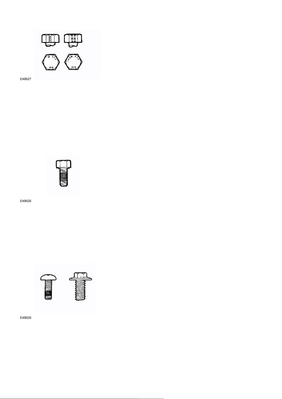
An ISO metric bolt or screw made of steel and larger than 6 mm in diameter can be identified by either of the symbols ISO
M or M embossed or indented on top of the bolt head.
In addition to marks identifying the manufacturer, the top of the bolt head is also marked with symbols indicating the
strength grade e.g. 8.8, 10.9, 12.9, 14.9. Alternatively, some bolts and screws have the M and strength grade symbol
stamped on the flats of the hexagon.
Encapsulated ('Patched') bolts and screws
Encapsulated ('patched') bolts and screws have a thread locking agent applied to the threads during manufacture. Most
thread locking agents are colored, the band of color extending for 360 degrees around the thread. Some locking agents
however, are neutral in color and may not be so easily identified apart from a slightly darker area of thread where the
locking agent has been applied. The locking agent is released and activated by the tightening process and is then
chemically cured to provide the locking action.
Self-locking bolts and screws
Unless stated in a specific repair procedure, self-locking bolts and screws i.e. nylon patched or trilobular thread can be
reused provided that resistance is felt when the locking portion enters the female thread.
Nylon patched bolts and screws have a locking agent either applied to, or inserted in the threaded portion. They are
identified by the presence of a colored section of thread extending approximately 180 degrees around the thread or by a
colored plug inserted into the bolt.
Page 6
07/16/2006 12:59 PMhttp://www.landrovertechinfo.com/extlrprod/frmviewit.jsp?szFrom=doc&iDocCode=276785
Page 6 of 25http://www.landrovertechinfo.com/extlrprod/frmviewit.jsp?szFrom=doc&iDocCode=276785
Trilobular bolts have a special thread form which creates a slight interference with the thread of the hole or nut into which it
is screwed.
CAUTION: Do Not reuse self-locking fasteners in critical locations e.g. drive plates/flywheel or engine
bearings. Do not fit non self-locking fasteners where a self-locking fastener is specified.
Trilobular bolts should not be used as a substitute for patched bolts.
Nut identification
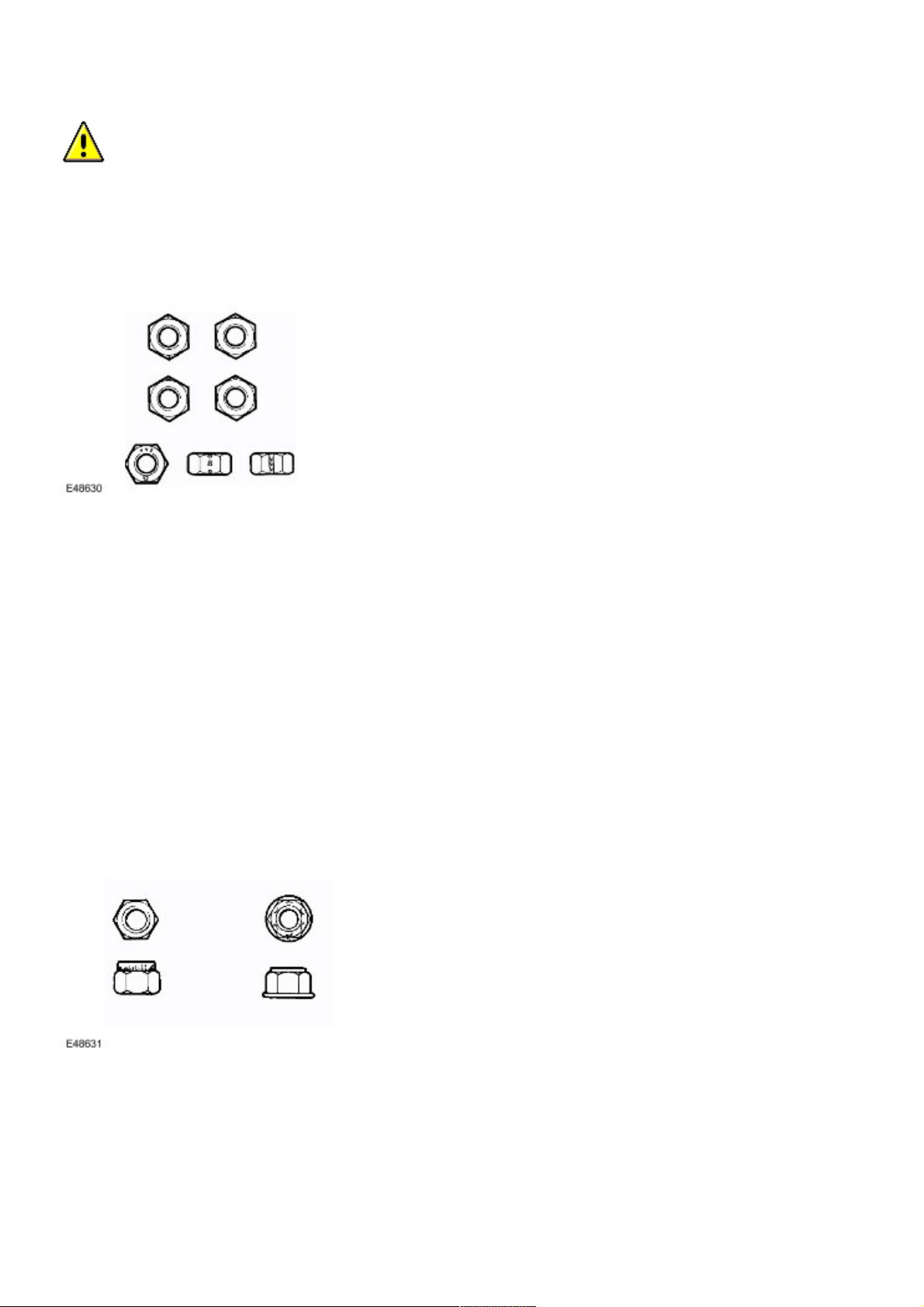
A nut with an ISO metric thread is marked on one face or one of the hexagonal flats with the strength grade symbol 8, 12,
14. Some nuts with the strength grade 4, 5 or 6 are also marked and some have the metric symbol M on the hexagonal flat
opposite the strength grade marking.
A clock face system is sometimes used as an alternative method of indicating the strength grade. The external chamfers or
a face of the nut is marked in a position relative to the appropriate hour mark on a clock face to indicate the strength grade.
A dot is used to locate the 12 o'clock position and a dash to indicate the strength grade. If the grade is above 12, two dots
identify the 12 o'clock position.
When tightening a slotted or castellated nut, never loosen it to insert a split pin except where specified as part of an
adjustment procedure. If difficulty is experienced in correctly positioning the slot, alternative washers or nuts should be
selected.
Where a nut is tightened to adjust or maintain bearing pre-load, the tightening procedure must be adhered to.
Self-locking nuts
Unless stated in a specific repair procedure, self-locking nuts i.e. those with a nylon insert or deformed thread nuts can be
reused provided that resistance can be felt when the locking portion of the nut passes over the thread of the bolt or stud.
Unless stated otherwise, self-locking nuts once removed must be discarded and new nuts of the same type and strength
grade fitted.
Page 7
07/16/2006 12:59 PMhttp://www.landrovertechinfo.com/extlrprod/frmviewit.jsp?szFrom=doc&iDocCode=276785
Page 7 of 25http://www.landrovertechinfo.com/extlrprod/frmviewit.jsp?szFrom=doc&iDocCode=276785
Air Suspension
Always ensure that suitable eye protection is worn when working on the air suspension system.
Ball and Roller Bearings
When removing and installing bearings, ensure that the following practices are observed to ensure component
serviceability:
CAUTION: Service tools have been developed for removing the majority of bearings; these must always be
used where specified.
Remove all traces from bearing under inspection by cleaning with a suitable degreasant; maintain absolute
cleanliness throughout operations.
Conduct a visual inspection for markings on rolling elements, raceways, outer surfaces of outer or inner surfaces of
inner rings. Reject any bearings found to be marked since marking in these areas indicates onset of wear.
Hold inner race of bearing between finger and thumb of one hand and rotate outer race to check that it revolves
absolutely smoothly. Repeat holding outer race and rotating inner race. DO NOT spin the bearing.
Rotate outer ring gently using a reciprocating movement whilst holding inner ring; feel for any check or obstruction to
rotation. Reject bearing if movement is not absolutely smooth.
Check bearing for blueing or signs of overheating.
Lubricate bearing with the specified lubricant.
Inspect bearing surface of shaft and bearing housing for discoloration or other markings which indicate overheating
of bearing or movement between bearing and seating.
Before fitting bearing, ensure that shaft and bearing housing are clean and free from burrs.
If one bearing of a pair shows signs of wear, overheating etc., it is advisable to replace bearings as a pair unless it is
suspected that one bearing may have been faulty when fitted, was fitted incorrectly or the fault arose due to oil seal
failure.
Never refit a bearing unless it is in a fully serviceable condition.
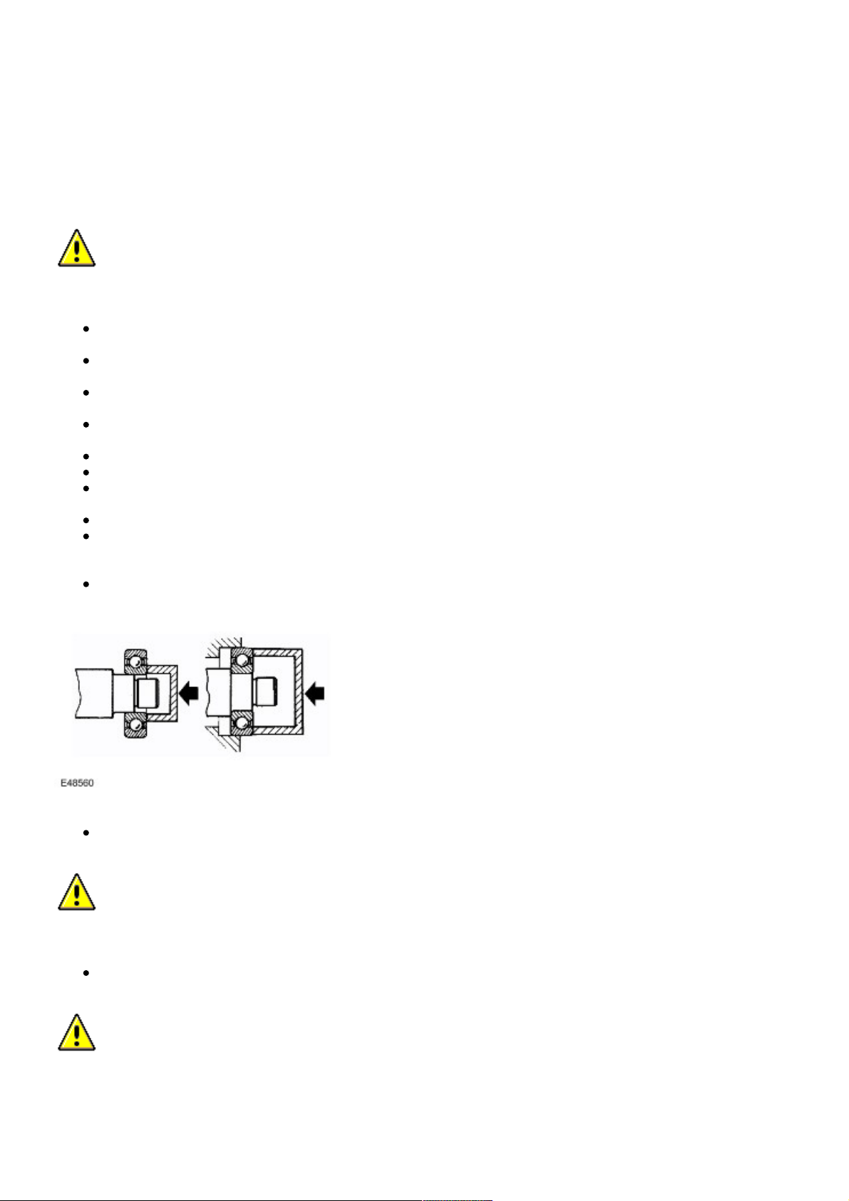
When fitting a bearing to a shaft, only apply force to the inner ring of the bearing. When fitting a bearing into a
housing, only apply force to the outer ring of the bearing.
CAUTION: Service tools have been developed for fitting the majority of bearings; these must always be
used where specified.
In the case of grease lubricated bearings, fill the space between the bearing and outer seal with the recommended
grade of grease before fitting the seal.
CAUTION: When a waxed oil seal (fitted dry) type of oil seal is to be fitted, take great care that grease does
not contaminate the running surface of the seal.
Page 8
07/16/2006 12:59 PMhttp://www.landrovertechinfo.com/extlrprod/frmviewit.jsp?szFrom=doc&iDocCode=276785
Page 8 of 25http://www.landrovertechinfo.com/extlrprod/frmviewit.jsp?szFrom=doc&iDocCode=276785
Always make suitable reference marks between the components of separable bearings e.g. taper roller bearings
when disassembling to ensure correct location of components when assembling. Never fit new rollers in an outer
ring, always fit a new bearing assembly.
Brake Pads and Linings
Always fit the correct grade and specification of brake pads and linings. When replacing these items, always replace as
complete axle sets.
Brake Hydraulics
Always observe the following recommendations when working on the braking system:
WARNING: Do not intermix brake fluid of different specifications.
Always use two spanners when loosening or tightening brake pipes or hose connections.
Ensure that hoses run in a natural curve and are not kinked or twisted.
Fit brake pipes and hoses securely in their retaining clips and ensure that they cannot contact a potential chafing
point.
Containers used for brake fluid must be kept absolutely clean.
Do not store brake fluid in unsealed containers, the fluid will absorb water which will lower the boiling point of the
fluid.
Do not allow brake fluid to be contaminated with other fluids such as mineral oil and do not put brake fluid in a
container which has previously been used for storing other fluids.
Do not reuse brake fluid which has been bled from the system.
Always use brake fluid or a suitable brake cleaning fluid to clean hydraulic components.
Unless stated otherwise, use only clean brake fluid to lubricate hydraulic seals and components.
Always fit blanking plugs to hoses, pipes or components immediately after disconnection.
Check thread compatibility of original equipment with replacement components.
Observe absolute cleanliness when working with hydraulic components.
Pipes and Hoses
When removing or installing flexible hydraulic pipes and hoses, ensure that the following procedures are observed to ensure
component serviceability:
Prior to removal, clean area around hose or pipe end which is to be disconnected.
Obtain appropriate blanking plugs or caps before disconnecting hose or pipe end fittings in order that connections
can be plugged immediately following disconnection.
Always fit blanking plugs or caps to pipes and unions immediately following disconnection.
Clean hose or pipe and blow through with an air line.
WARNING: Suitable eye protection must be worn.
Check hoses externally for cracks, separation of plies, security of end fittings and external damage; replace faulty
hoses.
Check pipes for signs of corrosion and chafing, replace as necessary.
CAUTION: If pipes are found to be chafed, rectify clips, mounting points etc., to prevent further problems in
service.
When fitting hoses, ensure that no unnecesary bends are introduced and that hoses are not kinked, twisted or
positioned close to potential chafing points.
When fitting pipes, ensure that pipes are positioned and clipped clear of potential chafing points.
Page 9
07/16/2006 12:59 PMhttp://www.landrovertechinfo.com/extlrprod/frmviewit.jsp?szFrom=doc&iDocCode=276785
Page 9 of 25http://www.landrovertechinfo.com/extlrprod/frmviewit.jsp?szFrom=doc&iDocCode=276785
Always replace sealing washers fitted to banjo bolts, sealing plugs etc.
Always use a backing spanner when tightening unions and do not overtighten union nuts or banjo bolts.
After any work on hydraulic systems, always check for fluid leaks whilst a second operator applies working pressure
to the brake pedal or operates the system that has been worked on.
Fuel system hoses
All fuel hoses are made up of two laminations, an armored rubber outer sleeve and an inner viton core. Whenever a hose is
removed, ensure that the inner bore is inspected to check that the viton lining has not become separated from the outer
sleeve.
WARNING: Never attempt to repair fuel foses or rectify leaking 'quick-fit' connectors the fuel hose and
connectors must be replaced as an assembly.
Fuel system hose clips
Certain fuel system hose clips are of the 'break-off head' type where a slot in the screw head shears off when the clip is
tightened to a specific torque. These clips may be removed using a screwdriver and must be replaced with new clips on
reassembly. Clips must be tightened until the portion of the slot shears off. Do not attempt to tighten clips by any other
method, do not fit any other type of clip.
Cooling system hoses
CAUTION: The following precautions must be observed to ensure that the integrity of the cooling system
hoses and their connection to the system is maintained.
Page 10
07/16/2006 12:59 PMhttp://www.landrovertechinfo.com/extlrprod/frmviewit.jsp?szFrom=doc&iDocCode=276785
Page 10 of 25http://www.landrovertechinfo.com/extlrprod/frmviewit.jsp?szFrom=doc&iDocCode=276785
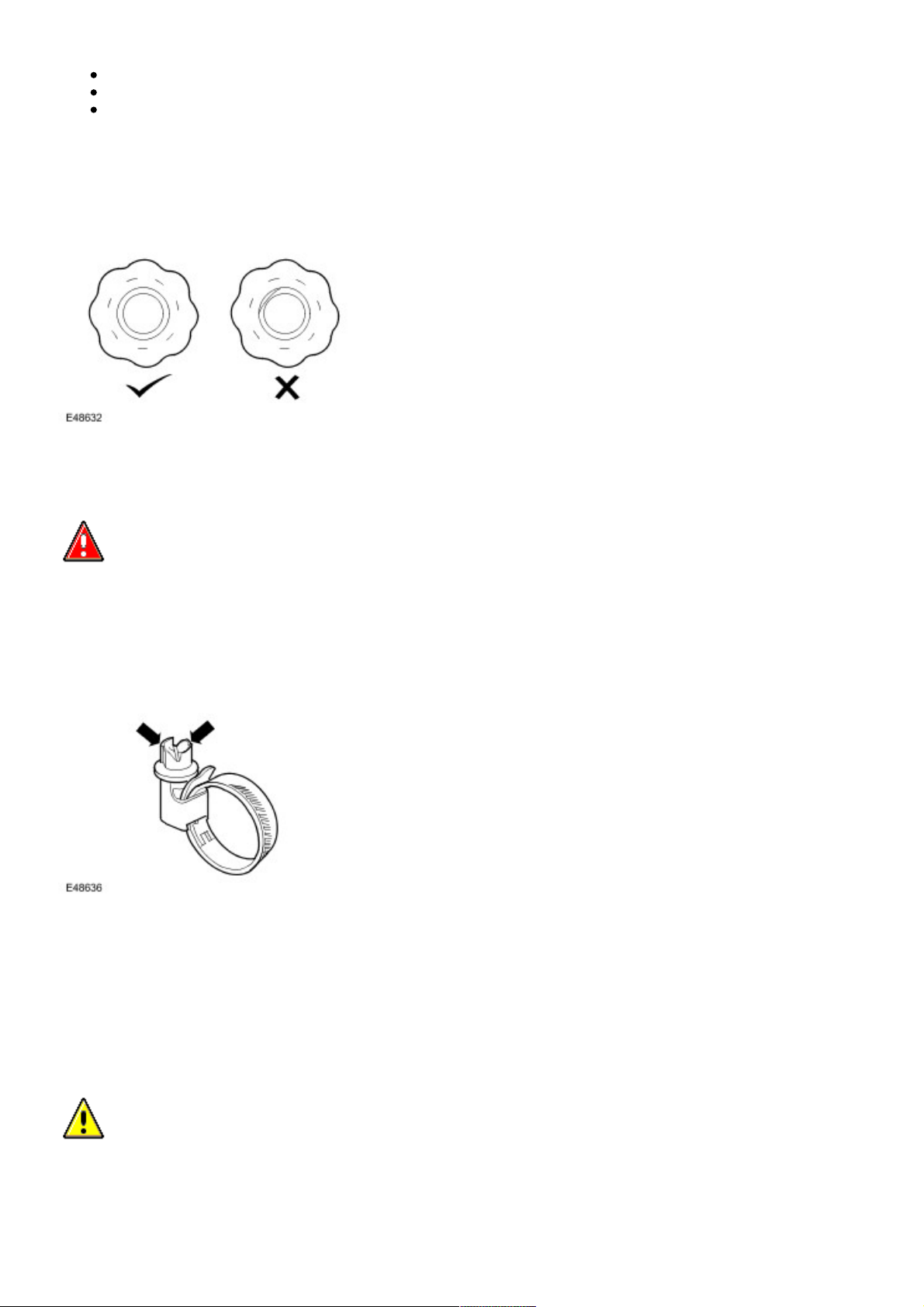
Hose orientation and connection
Correct orientation of cooling system hoses is important to ensure that hoses do not become fatigued or damaged through
contact with adjacent components.
Where orientation marks are provided on the hose and corresponding component, the marks must be aligned when the
hose is fitted. Hoses must be fitted fully on to their connection points, usually a moulded form on a pipe provides a positive
indicator.
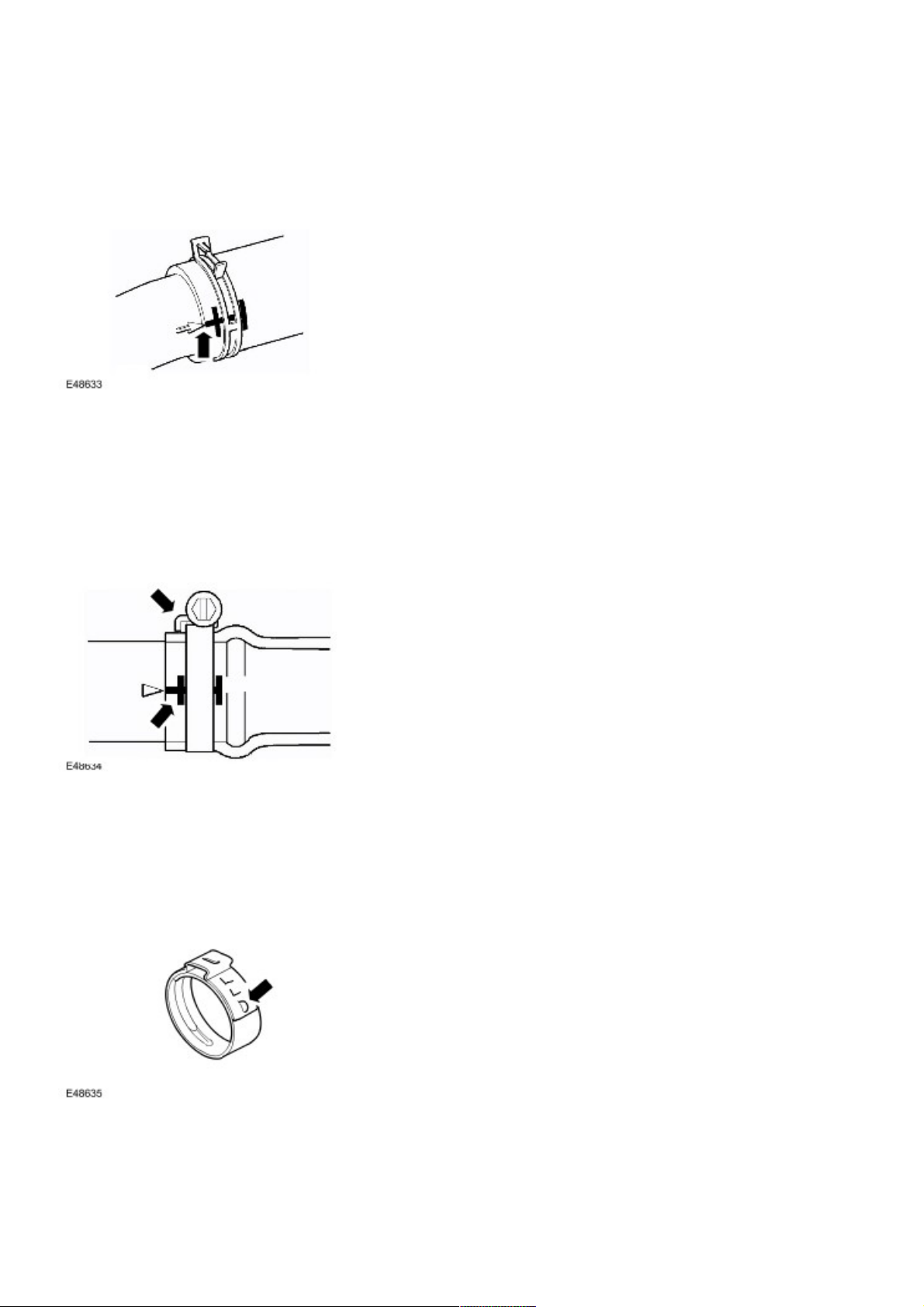
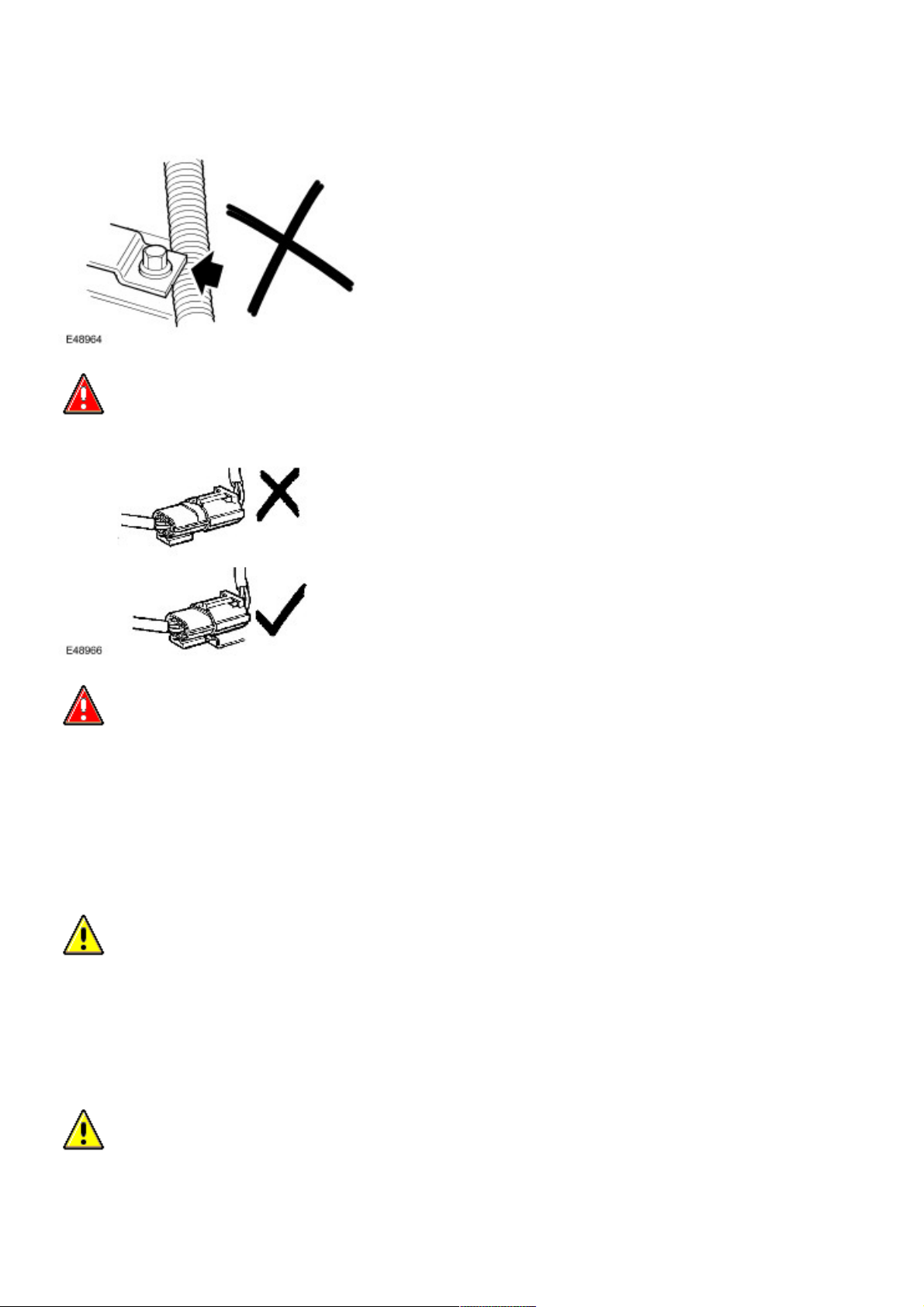
Hose clips
Markings are usually provided on the hose to indicate the correct clip position. If no markings are provided, position the clip
directly behind the retaining lip at the end of the stub pipe. Worm drive clips should be orientated with the crimped side of
the drive housing facing towards the end of the hose or the hose may become pinched between the clip and the stub pipe
retaining lip. Unless otherwise stated, worm drive clips should be tightened to 3 Nm (2 lbf.ft). Ensure that hose clips do not
foul adjacent components.
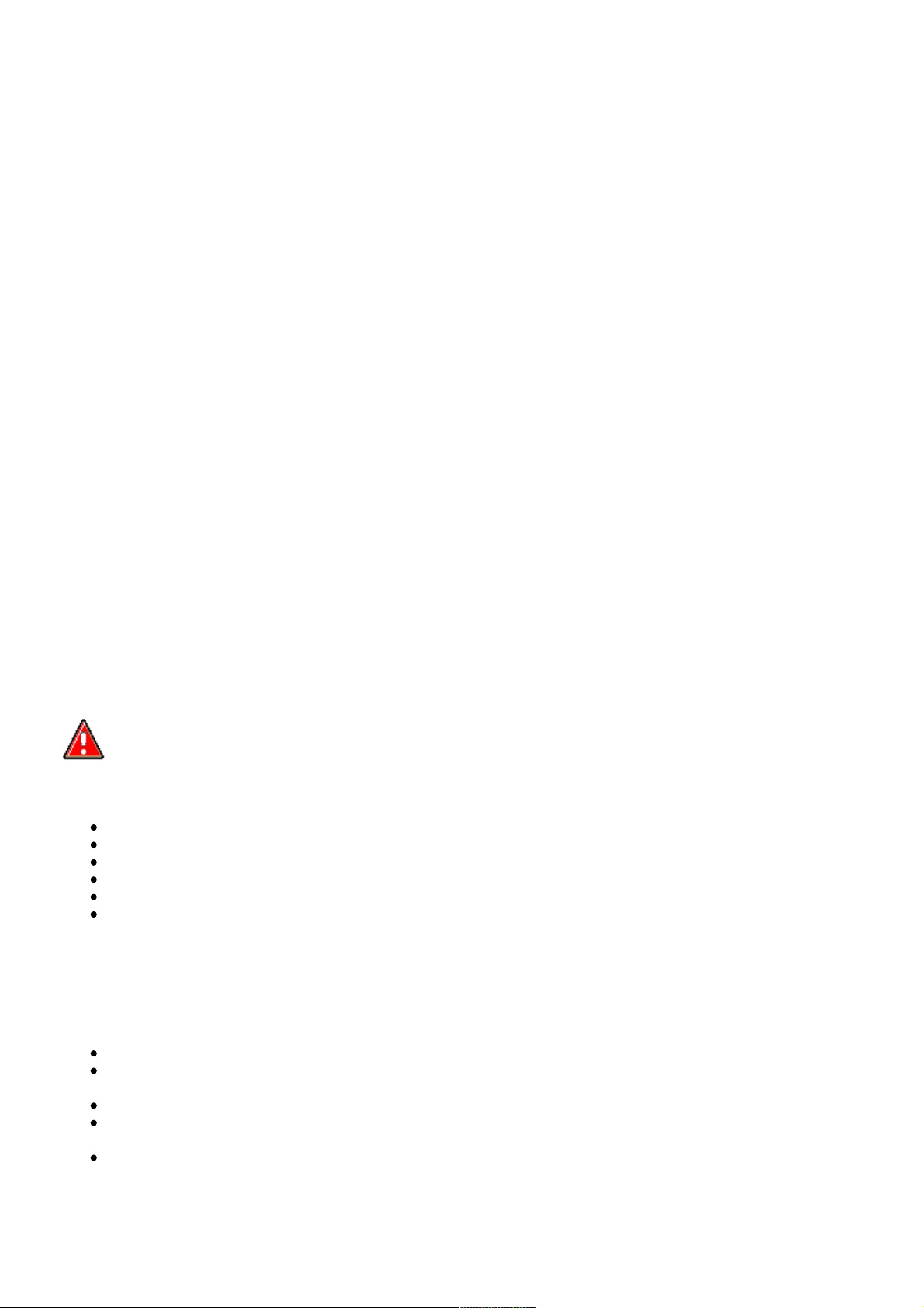
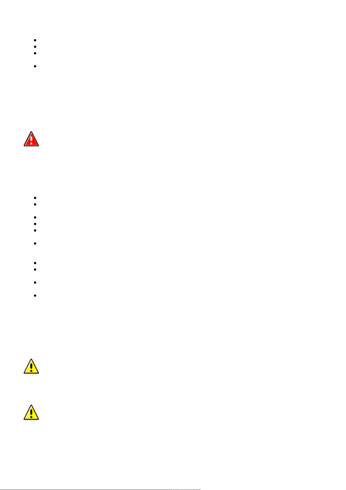
Oetiker clips may be removed by bending the tag (arrowed) and releasing the free end of the clip. Clips must not be reused.
When fitting new clips, ensure clip is positioned on hose before tightening and ensure that when clip is tightened, the tag is
located in the longitudinal slot in the free end of the clip (arrowed in illustration).
Page 11
07/16/2006 12:59 PMhttp://www.landrovertechinfo.com/extlrprod/frmviewit.jsp?szFrom=doc&iDocCode=276785
Page 11 of 25http://www.landrovertechinfo.com/extlrprod/frmviewit.jsp?szFrom=doc&iDocCode=276785
Heat protection
Always ensure that heatshields and protective sheathing are in good condition; replace if damage is evident. Particular care
must be taken when routing hoses close to hot engine components such as the exhaust manifolds and exhaust gas
recirculation (EGR) pipes. Hoses will relax and deflect slightly when hot, ensure this movement is taken into account when
routing and securing hoses.
Electrical Precautions
General
The following guidelines are intended to ensure the safety of the operator whilst preventing damage to the electrical and
electronic components of this vehicle.
Equipment
Prior to commencing any test procedure on the vehicle, ensure that the relevant test equipment is working correctly and that
any harness or connectors are in good condition. It is particularly important to check the condition of all plugs and leads of
mains operated equipment.
Polarity
Never reverse connect the vehicle battery and always ensure the correct polarity when connecting test equipment.
High voltage circuits
Whenever disconnecting live ht circuits, always use insulated pliers and never allow the open end of the ht lead to contact
other components, particularly ECU's.
Vehicles fitted with Bi-Xenon headlamp bulbs
WARNING: The following precautions must be observed as failure to comply may result in exposure to
ultra-violet rays, severe electric shock, burns or risk of an explosion.
Safety goggles and gloves must be worn.
Ensure that headlamps are switched off before removing bulbs.
Do not touch the glass portion of the bulb.
On no account should headlamps be switched on with the bulb removed from the headlamp.
Bulb testing may only be carried out with the bulb fitted in the headlamp.
Bulbs must be disposed of in accordance with the local authority bye-laws.
Connectors and harnesses
The engine compartment of a vehicle is a particularly hostile environment for electrical components and connectors. Always
observe the following:
Ensure electrically related items are dry and oil free before disconnecting/connecting test equipment.
Ensure that disconnected multiplugs and sensors are protected from any possible oil, coolant or other liquid
contamination. Any such contamination could impair performance or lead to component failure.
Never force connectors apart or pull on the wiring harness.
Always ensure locking tabs are disengaged before disconnecting multiplugs etc. and ensure that correct orientation
is achieved before connection.
Ensure that any protection covers, insulation etc. are replaced if disturbed.
Having confirmed that a component is faulty, carry out the following:
Page 12

07/16/2006 12:59 PMhttp://www.landrovertechinfo.com/extlrprod/frmviewit.jsp?szFrom=doc&iDocCode=276785
Page 12 of 25http://www.landrovertechinfo.com/extlrprod/frmviewit.jsp?szFrom=doc&iDocCode=276785
Switch off the ignition and disconnect the battery.
Remove the component and support the disconnected harness.
When replacing electrical components, keep oily hands away from electrical connections and ensure that locking
tabs on connectors are fully engaged.
Battery Disconnection/Connection
Always refer to the Electrical Section of this manual - Battery Connection/Disconnection prior to attempting to connect or
disconnect the battery. For additional information, refer to Specifications (414-00 Charging System - General Information)
Fuel Handling Precautions
The following information lists basic precautions which must be observed if fuel is to be handled safely. It also outlines other
areas of risk which must not be ignored. As this information is issued for basic guidance only, consult your local Fire
Department where any doubt as to personal and environmental safety exists - See also Health and Safety Precautions.
General precautions
Always have the correct type of fire extinguisher containing Foam, CO2, Gas or powder accessible when handling or
draining fuel or dismantling fuel systems. Fire extinguishers must also be located in areas where fuel is stored.
Ensure that suitable warning signs are exhibited.
Keep all sources of ignition well away from areas where fuel is being handled.
Ensure that any leadlamps are flameproof and kept clear of spillage.
WARNING: Do not disassemble or reassemble fuel system components whilst vehicle is over a pit.
WARNING: No one should be permitted to repair components associated with fuel without first having
specialist training.
Always disconnect the vehicle battery before carrying out disassembly, reassembly or draining work on a fuel system.
Fuel tank and system draining
Draining must be carried out in accordance with the procedures given in the relevant Fuel System section of this manual.
WARNING: Never drain fuel or work on a fuel system while the vehicle is over a pit. Extraction or draining
of fuel must be carried out in a well ventilated area.
WARNING: Always attach fuel vapor warning labels to fuel tanks immediately after draining.
WARNING: Containers used for storing fuel must be clearly marked with the contents and placed in a safe
storage area which meets the requirements of the local authority.
Page 13
07/16/2006 12:59 PMhttp://www.landrovertechinfo.com/extlrprod/frmviewit.jsp?szFrom=doc&iDocCode=276785
Page 13 of 25http://www.landrovertechinfo.com/extlrprod/frmviewit.jsp?szFrom=doc&iDocCode=276785
CAUTION: Some fuel lines are now fitted with 'quick release' connectors. If a connector is damaged, no
attempt must be made to repair the connector, a new fuel line and connector(s) assembly must be fitted.
Always release pipe clips fully before attempting to disconnect fuel pipes.
Fuel tank repairs
CAUTION: No attempt should be made to repair a plastic fuel tank. If the structure of the tank is damaged, a
new tank must be fitted.
Oil seals
Always renew oil seals which have been removed either as an individual component or as part of an assembly. Never use a
seal which has been improperly stored or handled.
Take great care when removing old seals that the sealing surfaces and seal housing are not damaged.
Carefully examine seal before fitting to ensure that it is clean and undamaged.
Ensure that the surface on which the seal is to run and also the seal housing is clean and free from burrs or
scratches. Renew the component if the sealing surface cannot be restored.
Special tools and protection sleeves are provided for fitting the majority of seals and must be used when specified.
Many seals are now coated with a protective wax and DO NOT need to be lubricated prior to fitting. Always check
the relevant repair procedure which will state if a seal must be fitted dry. Never touch these seals with oily hands as
the oil will contaminate the protective coating and affect the sealing properties of the seal; also, ensure that fitting
tools and protection sleeves are free from oil and grease. Seals which must be lubricated prior to fitting should have
the recommended lubricant applied to the areas specified in the repair procedure.
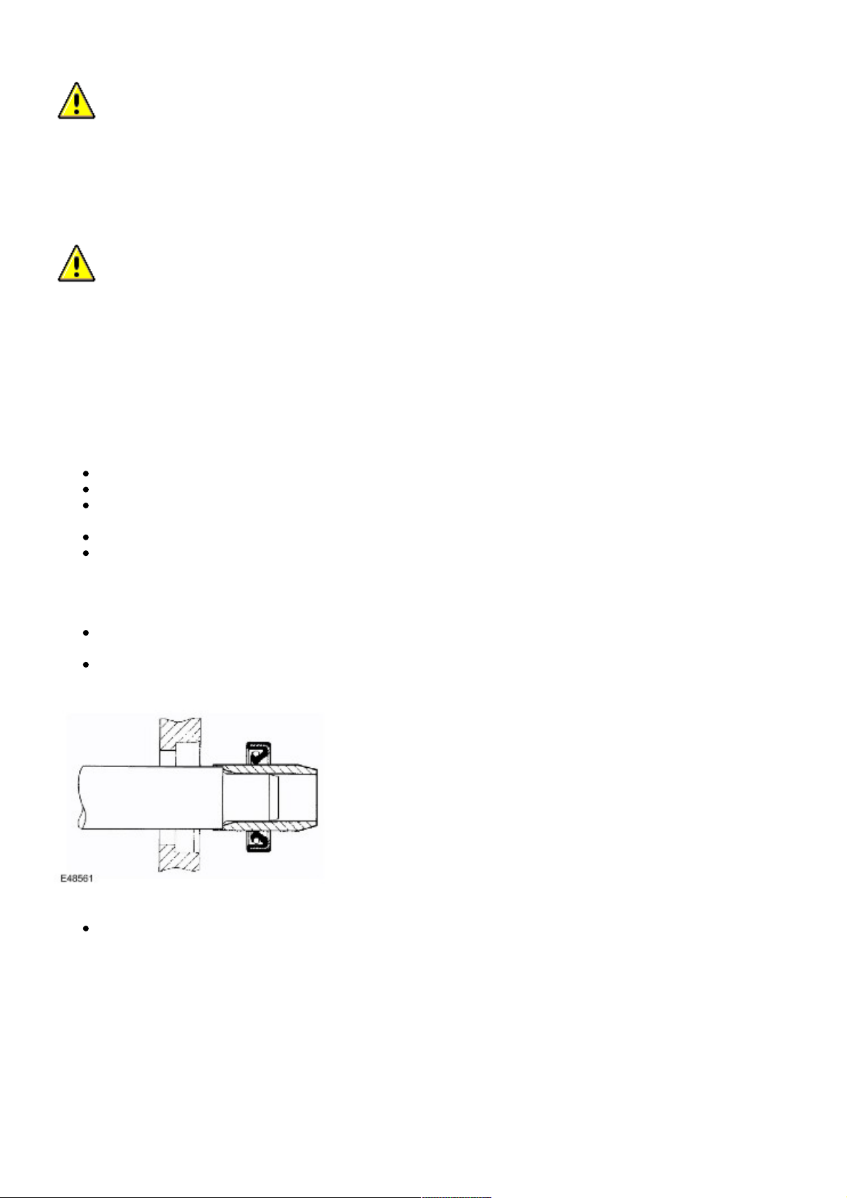
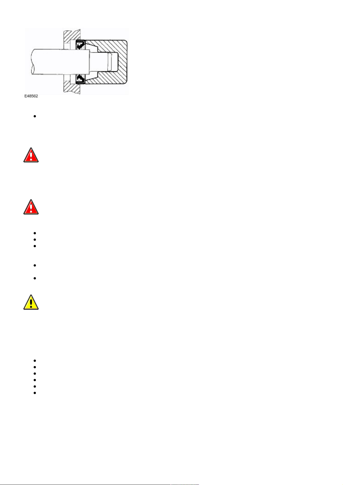
Ensure that a seal is fitted the correct way round. For example, the lip of the seal must face towards the lubricant
which it is sealing.
When fitting an oil seal, ensure that it is positioned square to shaft and housing. Where the seal is to be fitted to a
housing prior to fitting over a shaft, take care not to allow the weight of an unsupported shaft to rest on the seal.
Always use the recommended special tool and protection sleeve to fit an oil seal. If no tool is specified, use a
suitable mandrel approximately 0.4 mm (0.015 in) smaller than the outside diameter of the seal. Use adhesive tape
on the shaft to protect the sealing lip of the seal.
Page 14
07/16/2006 12:59 PMhttp://www.landrovertechinfo.com/extlrprod/frmviewit.jsp?szFrom=doc&iDocCode=276785
Page 14 of 25http://www.landrovertechinfo.com/extlrprod/frmviewit.jsp?szFrom=doc&iDocCode=276785
Press or drift the seal in to the depth of its housing if the housing is shouldered or flush with the face of the housing
where no shoulder is provided. Ensure that the seal is not tilted in the housing when it is fitted.
Supplementary Restraint System (SRS) Precautions
WARNING: Do not fit rear facing child seats in the front passenger seat.
The SRS contains components which are potentially hazardous to service personnel if not handled correctly. The following
guidelines and precautions are intended to alert personnel to potential sources of danger and emphasise the importance of
ensuring the integrity of the SRS components fitted to the vehicle.
WARNING: The following precautions MUST be adhered to when working on the SRS system:
The correct procedures must always be used when working on SRS components.
Persons working on the SRS system must be fully trained and have been issued with the safety guidelines.
The airbag modules contain extremely flammable and hazardous compounds. Contact with water, acids or
heavy metals may produce harmful or explosive results. Do not dismantle, incinerate or bring into contact
with electricity before the unit has been deployed.
Always replace a seat belt assembly that has withstood the strain of a severe vehicle impact or if the
webbing shows signs of fraying.
Always disconnect the vehicle battery before carrying out any electric welding on a vehicle fitted with an
SRS system.
CAUTION: Do not expose airbag modules or seat belt pre-tensioners to temperatures exceeding 85° C (185°
F).
It should be noted that these precautions are not restricted to operations performed when servicing the SRS system. The
same care should be exercised when working on ancillary systems and components located in the vicinity of SRS
components; these include but are not limited to:
Steering wheel airbag, rotary coupler.
Passenger front airbag.
Head airbag modules - front and rear.
Seat belt pre-tensioners.
SRS harnesses, link leads and connectors.
Side (thorax) air bags.
Making the system safe
Before working on or in the vicinity of SRS components, ensure the system is rendered safe by performing the following
operations:
Page 15
07/16/2006 12:59 PMhttp://www.landrovertechinfo.com/extlrprod/frmviewit.jsp?szFrom=doc&iDocCode=276785
Page 15 of 25http://www.landrovertechinfo.com/extlrprod/frmviewit.jsp?szFrom=doc&iDocCode=276785
Remove the ignition key.
Disconnect battery, earth lead first.
Wait 2 minutes for the SRS power circuit to discharge before commencing work.
NOTE:
The SRS uses energy reserve capacitors to keep the system active in the event of electrical supply failure under
crash conditions. It is necessary to allow the capacitors sufficient time to discharge (2 minutes) in order to avoid the
risk of accidental deployment.
Installation
In order to ensure system integrity, it is essential that the SRS system is regularly checked and maintained so that it is
ready for effective operation in the event of a collision. Carefully inspect SRS components before installation. Do not install
a part that shows signs of being dropped or improperly handled, such as dents, cracks or deformation.
WARNING: The integrity of the SRS systems is critical for safety reasons. Ensure the following precautions
are always adhered to:
Do not fit accessories or other objects to trim panels which cover ITS airbags.
Never install used SRS components from another vehicle or attempt to repair an SRS component.
When repairing an SRS system, only use genuine new parts.
Never apply electrical power to an SRS component unless instructed to do so as part of an approved test
procedure.
Special fixings are necessary for installing an airbag module – do not use other fixings and ensure that all
fixings are tightened to the correct torque.
Always use new fixings when replacing an SRS component.
CAUTION: Take care not to trap airbag modules when fitting interior trim components.
CAUTION: Ensure SRS components are not contaminated by oil or grease.
NOTE:
Following seat belt pre-tensioner deployment, the seat belts can still be used as conventional seat belts but will need
to be replaced as soon as possible to ensure full SRS protection.
NOTE:
If the SRS components are to be replaced, the part number/bar code of the new unit must be recorded.
SRS component testing precautions
The SRS components are triggered using relatively low operating currents, always adhere to the following :
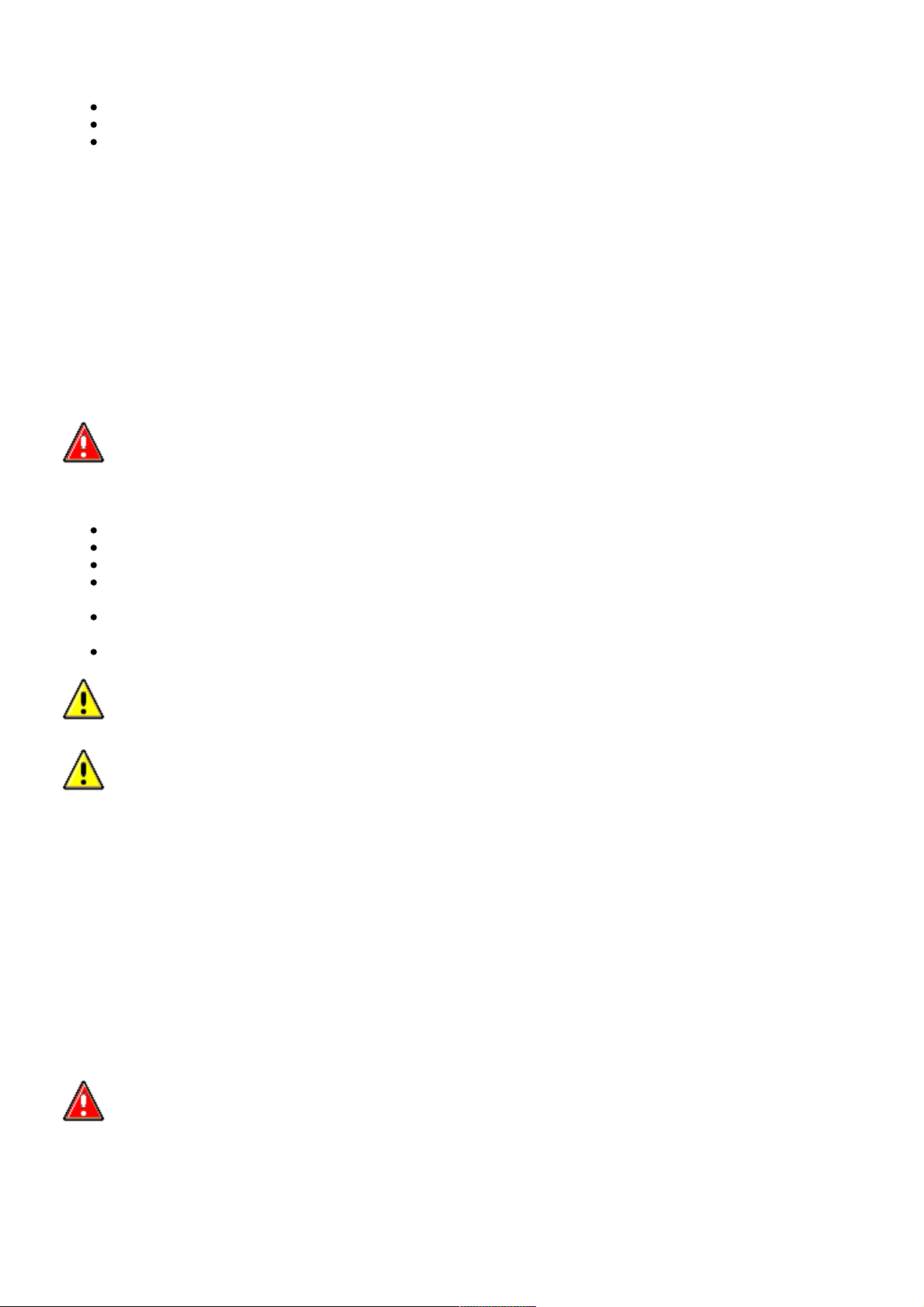
WARNING: Never use a multimeter or other general purpose equipment on SRS components. Use only T4
to diagnose system faults.
Page 16
07/16/2006 12:59 PMhttp://www.landrovertechinfo.com/extlrprod/frmviewit.jsp?szFrom=doc&iDocCode=276785
Page 16 of 25http://www.landrovertechinfo.com/extlrprod/frmviewit.jsp?szFrom=doc&iDocCode=276785
WARNING: Do not use electrical test equipment on the SRS harness while it is connected to any of the SRS
components, it may cause accidental deployment and injury.
Handling and storage
Always observe the following precautions when handling SRS components:
Never drop an SRS component. The airbag diagnostic control unit is a particularly shock sensitive device and must
be handled with extreme care. Airbag modules and seat belt pre-tensioners could deploy if subjected to a strong
shock.
Never wrap your arms around an airbag module. If a module has to be carried, hold it by the cover with the cover
uppermost and the base away from your body.
Never transport airbag modules or seat belt pre-tensioners in the passenger compartment of a vehicle. Always use
the luggage compartment of the vehicle for carrying airbag modules and seat belt pre-tensioner units.
Never attach anything to an airbag cover or any trim component covering an airbag module. Do not allow anything to
rest on top of an airbag module.
Always keep components cool, dry and free from contamination.
Never apply grease or cleaning solvents to seat belt pre-tensioner units, component failure could result.
Always store an airbag module with the deployment side uppermost. If it is stored deployment side down, accidental
deployment will propel the airbag module with sufficient force to cause serious injury.
Keep new airbag modules in their original packaging until just prior to fitting. Place the old module in the empty
packaging for carriage.
Page 17
07/16/2006 12:59 PMhttp://www.landrovertechinfo.com/extlrprod/frmviewit.jsp?szFrom=doc&iDocCode=276785
Page 17 of 25http://www.landrovertechinfo.com/extlrprod/frmviewit.jsp?szFrom=doc&iDocCode=276785
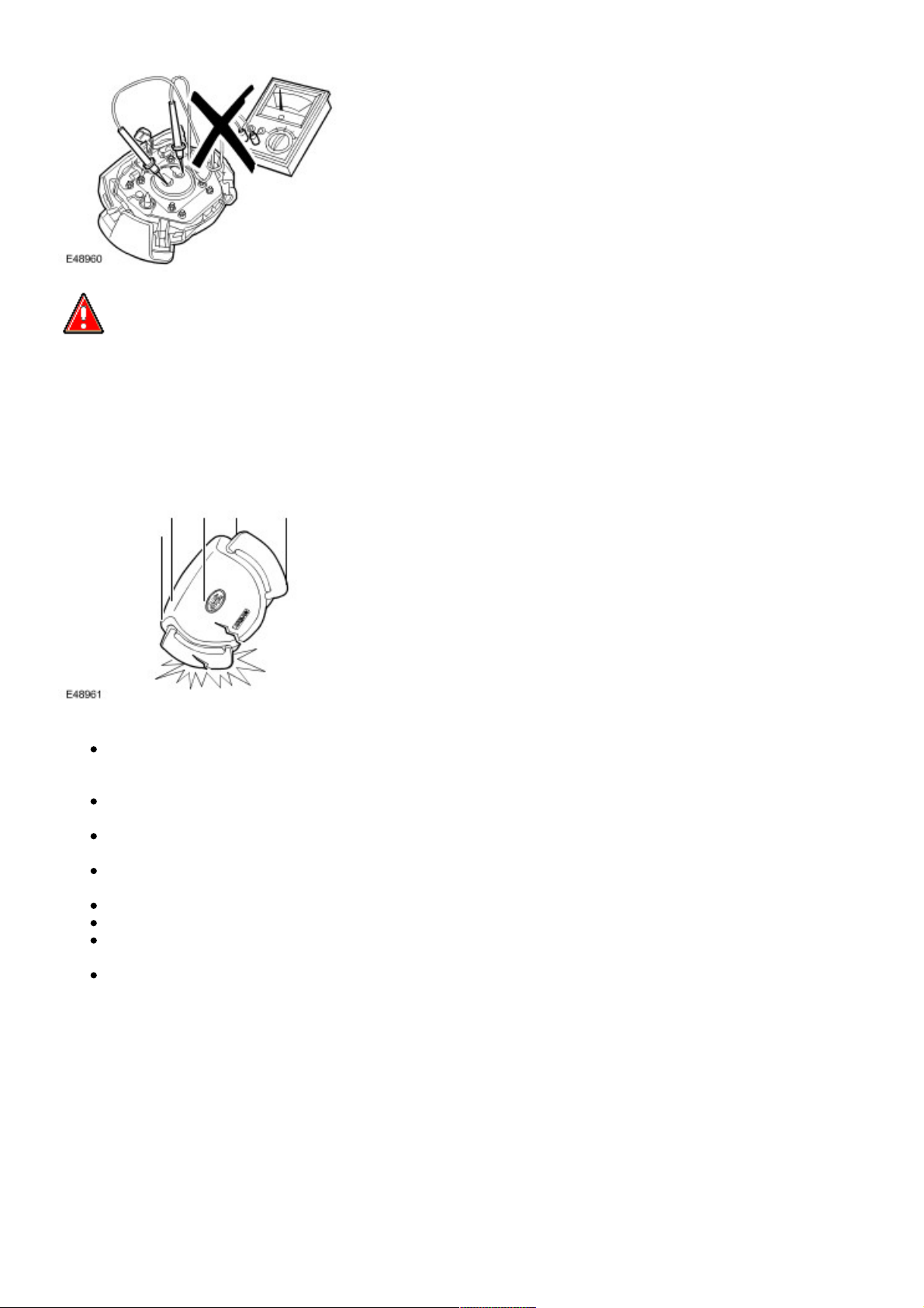
WARNING: When handling an inflatable tubular structure (ITS) airbag module, hold by the gas generator
housing, DO NOT hold by the airbag. Do not wrap the thumb around the gas generator while holding. Do not drape
airbag over shoulder or around neck. For seat buckle type pre-tensioners, hold by the piston tube, with the open
end of the piston tube pointing towards the ground and the buckle facing away from your body. Do not cover the
end of the piston tube. DO NOT hold buckle type pre-tensioners by the bracket assembly or cable. Never point the
piston tube towards your body or other people.
WARNING: Airbag modules and seat belt pre-tensioners are classed as explosive devices. For overnight
and longer term storage, they must be stored in a secure steel cabinet which has been approved as suitable for
the purpose and has been registered with the local authority.
WARNING: Store airbag modules or seat belt pre-tensioners in a designated storage area. If there is no
designated storage area available, store in the locked luggage compartment of the vehicle and inform the
workshop supervisor.
CAUTION: Improper handling or storage can internally damage the airbag module making it inoperative. If
you suspect the airbag module has been damaged, install a new module and refer to the deployment/disposal
procedures for disposal of the damaged module.
SRS harness and connectors
Always observe the following precautions with regards to SRS system electrical wiring:
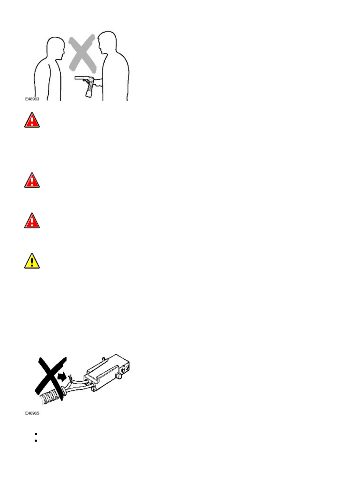
Never attempt to modify, splice or repair SRS wiring.
Never install electrical equipment such as a mobile telephone, two-way radio or in-car entertainment system in such
a way that it could generate electrical interference in the airbag harness. Seek specialist advice when installing such
equipment.
Page 18
07/16/2006 12:59 PMhttp://www.landrovertechinfo.com/extlrprod/frmviewit.jsp?szFrom=doc&iDocCode=276785
Page 18 of 25http://www.landrovertechinfo.com/extlrprod/frmviewit.jsp?szFrom=doc&iDocCode=276785
NOTE:
SRS wiring can be identified by a special yellow outer sleeve protecting the wires (black with yellow stripe protective
coverings are sometimes used).
WARNING: Always ensure SRS wiring is routed correctly. Be careful to avoid trapping or pinching the SRS
wiring.
WARNING: Do not leave the connectors hanging loose or allow SRS components to hang from their
harnesses. Look for possible chafing points.
Side impact crash sensor inspection
After any degree of side body damage, inspect the side impact crash sensors. Replace a crash sensor if there is any sign
of damage.
CAUTION: Take extra care when painting or carrying out bodywork repairs in the vicinity of the crash
sensors. Avoid direct exposure of the crash sensors or link harnesses to heat guns, welding or spraying
equipment. Take care not to damage sensor or harness when refitting components.
Rotary coupler
CAUTION: Always follow the procedure for fitting and checking the rotary coupler as instructed in the SRS
repairs section. Comply with all safety and installation procedures to ensure the system functions correctly.
Observe the following precautions:
Page 19
07/16/2006 12:59 PMhttp://www.landrovertechinfo.com/extlrprod/frmviewit.jsp?szFrom=doc&iDocCode=276785
Page 19 of 25http://www.landrovertechinfo.com/extlrprod/frmviewit.jsp?szFrom=doc&iDocCode=276785
Do not unlock and rotate the rotary coupler when it is removed from the vehicle.
Do not turn the road wheels when the rotary coupler is removed from the vehicle.
Always ensure the rotary coupler is removed and installed in its central position and with the front road wheels in the
straight ahead position - refer to SRS repair section for the correct removal and installation procedure.
If a new rotary coupler is being installed, ensure the locking tab holding the coupler's rotational position is not broken;
units with a broken locking tab must not be used.
Airbag location labels
WAITING AIRBAG LOCATION AND DESIGN LABELS - DUE MARCH - NEIL HARRISON 46404
Airbag and pre-tensioner deployment
WARNING: During deployment parts of the airbag module become hot enough to burn you. Wait 30 minutes
after deployment before touching the airbag module.
Deployment procedures and precautions as detailed in this manual should be strictly adhered to. Only personnel who have
undergone the appropriate training should undertake deployment of airbag and pre-tensioner modules. The following
precautions must be complied with:
Only use deployment equipment approved for the intended purpose.
Deployment of airbag / pre-tensioner modules must be performed in a well ventilated area which has been
designated for the purpose.
Ensure airbag / pre-tensioner modules are not damaged or ruptured before attempting to deploy.
Where local legislation exists, notify the relevant authorities of intention to deploy airbag and pretensioner units.
When deploying airbag pre-tensioner units, ensure that all personnel are at least 15 metres (45 feet) away from the
deployment zone.
Ensure deployment tool is connected correctly, in compliance with the instructions detailed in the SRS section of this
manual. In particular, ensure deployment tool is NOT connected to battery supply before connecting to airbag
module connector.
When deploying seat belt pre-tensioners, ensure pre-tensioner unit is secured correctly to the seat.
When removing deployed airbag modules and pre-tensioner units, wear protective clothing. Use gloves and seal
deployed units in a plastic bag.
Following deployment of any component of the SRS system within the vehicle, all SRS components must be
replaced. DO NOT reuse or salvage any parts of the SRS system.
Do not lean over an airbag module when connecting deployment equipment.
If a vehicle is to be scrapped, undeployed airbag modules and pre-tensioner units must be manually deployed. In this case
airbags can be deployed in the vehicle. Before deployment, ensure the airbag module is secure within its correct mounting
position. Deployment of the driver's airbag in the vehicle may damage the steering wheel; if the vehicle is not being
scrapped, deploy the module outside of the vehicle.
SRS Component Replacement Policy
CAUTION: The Restraints Control Module (RCM) will log a crash fault after every impact which is severe
enough to cause airbag deployment. It is possible to have three crashes/impacts logged after one event where,
for example, a front, side and rollover has occurred. After the third fault is logged, the SRS warning lamp will be
illuminated and the restraints control module (RCM) must be replaced.
CAUTION: The SRS side impact sensor must be replaced if there are any signs of physical damage or if the
restraints control module (RCM) is registering a fault.
The following information details the policy for replacement of SRS components as a result of a vehicle accident.
Page 20
07/16/2006 12:59 PMhttp://www.landrovertechinfo.com/extlrprod/frmviewit.jsp?szFrom=doc&iDocCode=276785
Page 20 of 25http://www.landrovertechinfo.com/extlrprod/frmviewit.jsp?szFrom=doc&iDocCode=276785
Impacts which do not deploy the airbags or pre-tensioners
Check for structural damage in the area of the impact paying particular attention to bumper armatures, longitudinals and
bracketry.
Impacts which deploy the airbags or pre-tensioners
The replacement and inspection policy is dependent on the type and severity of the crash condition. The following
guidelines are the minimum that should be exercised as a result of the deployment of specific SRS components.
Check for structural damage in the area of impact paying particular attention to bumper armatures, longitudinals
and bracketry.
Front Airbag Deployment - Driver and Passenger
CAUTION: If the front airbags are deployed, the following components must be replaced:
Driver airbag module
Passenger airbag module
Fly leads (where applicable) connecting front airbag modules to SRS harness
Front seat belt buckle pre-tensioner
Rear seat belt pre-tensioners - if fitted
Driver's seat belt retractor - if fitted
Rotary coupler
Any front impact sensors that have been physically damaged or if a fault is being registered
Restraints control module (RCM) if the three crashes/impacts have been stored
Additionally, the following items must be inspected for damage and replaced as necessary:
Front passenger's seat belt retractor and webbing, tongue latching function, 'D' loop and body anchorage point
Rear seat belt buckles, webbing, buckle covers, body anchorage points and tongue latching function
Fascia moulding adjacent to passenger airbag module
Steering wheel
Front seat frames and head restraints
Steering column - if adjustment is lost or if there are signs of collapse
Seat belt height adjusters
Rear seat belts
Side Air Bags
CAUTION: If the side (thorax) air bags are deployed, the following components must be replaced on the
side of the vehicle on which the deployment occurred:
Side (thorax) airbag
Any side impact sensors that have been physically damaged or if a fault is being registered
Restraints Control Module (RCM) if the three crashes/impacts have been stored
Additionally, the following items must be inspected for damage and replaced as necessary:
Front seat belts, retractors and webbing, tongue latching function, 'D' loop and body anchorage points
Rear seat belt buckles, webbing, buckle covers, tongue latching function, and body anchorage points
Front seat frame and head restraints
Door trim casing
Seat belt height adjusters
Rear seat belts
Page 21
07/16/2006 12:59 PMhttp://www.landrovertechinfo.com/extlrprod/frmviewit.jsp?szFrom=doc&iDocCode=276785
Page 21 of 25http://www.landrovertechinfo.com/extlrprod/frmviewit.jsp?szFrom=doc&iDocCode=276785
Head airbag modules
CAUTION: If the head airbag modules are deployed, the following components must be replaced on the
side of the vehicle on which the deployment occurred:
Head airbag modules
Link lead between airbag gas generator and restraints control module (RCM) harness
Airbag retaining clips
Internal trim finisher
Front seat belt buckle pre-tensioners
Any side impact sensors that have been physically damaged or if a fault is being registered
Restraints Control Module (RCM) if the three crashes/impacts have been stored
Additionally, the following items must be inspected for damage and replaced as necessary:
Headlining
Component mounting brackets
Front seat belts, retractors and webbing, tongue latching function, 'D' loop and body anchorage points
Rear seat belt buckles, webbing, buckle covers, tongue latching function, and body anchorage points
Adjacent trim components
Seat belt height adjusters
Rear impacts
CAUTION: If the seat belt pre-tensioners are deployed during a rear impact, the following components must
be replaced:
Seat belt pre-tensioners
Front and rear seat belt retractors used during the impact
Restraints Control Module (RCM) if the three crashes/impacts have been stored
Additionally, the following items must be inspected for damage and replaced as necessary:
Seat belt height adjusters
Front seat belts, retractors and webbing, tongue latching function, 'D' loop and body anchorage points
Rear seat belt buckles, webbing, buckle covers, tongue latching function, and body anchorage points
Air Conditioning System Precautions
The air conditioning system contains fluids and components which could be potentially hazardous to the service engineer or
the environment if not serviced and handled correctly. The following guidelines are intended to alert the service engineer to
potential sources of danger and emphasise the importance of ensuring the integrity of the Air Conditioning operating
conditions and components fitted to the vehicle.
Where necessary, additional specific precautions are detailed in the relevant sections of this Manual and also in the Health
and Safety Section. These precautions must be referred to prior to commencing repair operations.
The refrigerant used in the air conditioning system is HFC-134a (Hydrofluorocarbon) R134a.
WARNING: Servicing must only be carried out by personnel familiar with both the vehicle system and the
charging and testing equipment. All operations must be carried out in a well ventilated area away from open flame
Page 22

07/16/2006 12:59 PMhttp://www.landrovertechinfo.com/extlrprod/frmviewit.jsp?szFrom=doc&iDocCode=276785
Page 22 of 25http://www.landrovertechinfo.com/extlrprod/frmviewit.jsp?szFrom=doc&iDocCode=276785
and heat sources.
WARNING: R134a is a hazardous liquid and when handled incorrectly can cause serious injury. Suitable
protective clothing, consisting of face protection, heat proof gloves, rubber boots and rubber apron or waterproof
overalls, must be worn when carrying out operations on the air conditioning system.
Remedial actions
WARNING: Due to its low evaporating temperature, R134a must be handled with care. R134a splashed on
any part of the body will cause immediate freezing of that area. Also, refrigerant cylinders and replenishment
trolleys when discharging will freeze skin to them if contact is made.
If an accident involving R134a should occur, conduct the following remedial actions:
If liquid R134a enters the eye, do not rub it. Gently run large quantities of eye wash over affected eye to raise the
temperature. If an eye wash is not available, cool, clean water may be used to flush the eye. After rinsing, cover the
eye with a clean pad and seek immediate medical attention.
If liquid R134a is splashed onto the skin, run large quantities of water over the affected area to raise the
temperature. Implement the same action if the skin comes in contact with discharging cylinders. Wrap the
contaminated body parts in blankets (or similar materials) and seek immediate medical attention.
If the debilitating effects of inhalation of R134a vapour are suspected, seek fresh air. If the affected person is
unconscious, move them away from the contaminated area to fresh air and apply artificial respiration and/or oxygen
and seek immediate medical attention.
Service precautions
Observe the following precautions when handling components used in the air conditioning system:
Air conditioning units must not be lifted by their hoses, pipes or capillary lines.
Hoses and lines must not be subjected to any twist or stress; the efficiency of the system will be impaired by kinks or
restrictions. Ensure that hoses are correctly positioned before tightening couplings, and ensure that all clips and
supports are utilised.
Flexible hoses should not be positioned closer than 100 mm (4.0 in) to the exhaust manifold unless protected by
heat shielding.
Completed assemblies must be checked for refrigeration lines touching metal panels. Any direct contact of
components and panels may transmit noise and so must be eliminated.
The appropriate torque wrench must be used when tightening refrigerant connections to the stipulated value. An
additional spanner must be used to hold the union to prevent twisting of the pipe when tightening connections.
Before connecting any hose or pipe, ensure that refrigerant oil is applied to the seat of the new 'O' rings, BUT NOT
to the threads of the connection.
All protective plugs or caps must remain in place in the component until immediately prior to connection.
Ensure components are at room temperature before uncapping/unplugging, to prevent condensation of moisture
from the air that enters it.
When disconnecting, immediately plug or cap all air conditioning pipes to prevent ingress of dirt and moisture into
the system.
Components must not remain uncapped/unplugged, if a system has been left uncapped/unplugged for 20 minutes or
longer, a new receiver/drier must be fitted.
The receiver/drier contains desiccant which absorbs moisture. It must be positively sealed at all times. A
receiver/drier that has been left uncapped for longer than 20 minutes must not be used; fit a new unit.
The receiver/drier should be the last component connected to the system to ensure optimum dehydration and
maximum moisture protection of the system.
Whenever a component of the refrigeration system is replaced, it will also be necessary to fit a new receiver/drier
unit.
Use alcohol and a clean lint-free cloth to clean dirty connections.
Page 23
07/16/2006 12:59 PMhttp://www.landrovertechinfo.com/extlrprod/frmviewit.jsp?szFrom=doc&iDocCode=276785
Page 23 of 25http://www.landrovertechinfo.com/extlrprod/frmviewit.jsp?szFrom=doc&iDocCode=276785
Ensure that all new parts fitted are marked for use with R134a.
When a major repair has been completed, a leak test should be conducted; refer to the Repairs Section of this
manual for the correct procedure.
Refrigerant oil
CAUTION: Refrigerant oil easily absorbs water and must not be stored for long periods. Do not pour unused
refrigerant oil back into the container. Always use an approved refrigerant oil.
When replacing components in the air conditioning system, drain the refrigerant oil from the component being replaced into
a graduated container. On assembly, add the quantity of refrigerant oil drained to the new component - See Air Conditioning
Compressor Replacement in this Section.
Compressor
A new compressor is sealed and pressurised with Nitrogen gas. When fitting a new compressor, slowly release the sealing
cap; gas pressure should be heard to vent as the seal is broken.
CAUTION: A new compressor should always be sealed and could be pressurised with nitrogen gas. To
avoid possible oil loss, release the sealing cap(s) slowly. Do not remove the cap(s) until immediately prior to
connecting the air conditioning pipes to the compressor.
Rapid refrigerant discharge
If the air conditioning system is involved in accident damage and the system is punctured, the refrigerant will discharge
rapidly. The rapid discharge of refrigerant will also result in the loss of most of the oil from the system. The compressor must
be removed and all the remaining oil in the compressor drained and refilled as instructed in the air conditioning section of
this manual.
Precautions for refrigerant recovery, recycling and recharging
When the air conditioning system is recharged, any existing refrigerant is first recovered from the system and recycled. The
system is then charged with the required weight of refrigerant and volume of refrigerant oil.
WARNING: Refrigerant must always be recycled before reuse to ensure that the purity of the refrigerant is
high enough for safe use in the air conditioning system. Recycling should always be carried out with equipment
which is design certified by Underwriter Laboratory Inc. for compliance with SAE J1991. Other equipment may not
recycle refrigerant to the required level of purity.
CAUTION: A R134a Refrigerant Recovery Recycling Recharging Station must not be used with any other
type of refrigerant. Refrigerant R134a from domestic and commercial sources must not be used in motor vehicle
air conditioning systems.
Page 24
07/16/2006 12:59 PMhttp://www.landrovertechinfo.com/extlrprod/frmviewit.jsp?szFrom=doc&iDocCode=276785
Page 24 of 25http://www.landrovertechinfo.com/extlrprod/frmviewit.jsp?szFrom=doc&iDocCode=276785
CAUTION: The system must be evacuated immediately before recharging commences. Delay between
evacuation and recharging is not permitted.
Air Conditioning Compressor Replacement
A new compressor is supplied filled with a full charge (X cm³) of refrigerant oil.
A calculated quantity of oil must be drained from the new compressor before fitting. To calculate the quantity of oil to be
drained:
Remove the drain plug from the old compressor.
Invert the compressor and gravity drain the oil into a calibrated measuring cylinder. Rotate the compressor clutch to
ensure the compressor is completely drained.
Note the quantity of oil drained (Y cm³).
Calculate the quantity of oil to be drained from the new compressor using the following formula:X cm³ — (Y cm³ +
20 cm³) = Q cm³
Remove the drain plug from the new compressor and drain Q cm3 of oil. Fit and tighten the compressor drain plug.
Vehicle Weights
Item kg lb
Maximum Gross Vehicle Weight (GVW)
Petrol engine vehicles naturally aspirated 3070 6768
Petrol engine vehicles supercharged 3125 6889
Diesel engine vehicles 3070 6768
Maximum weight of unbraked trailer:
On-road 750 1650
Off-road 750 1650
Maximum towable weight (mass) - Trailers with overrun brakes
On-road 3500 7700
Off-road 1000 2205
Maximum roof rack load (Including the mass of the roof rack):
On-road 75 110
Off-road 75 110
Vehicle Dimensions
Item mm in
Length - including number plate plinth - All models 4798 188.9
Width - All models:
Mirrors extended 2170 85.4
Mirrors folded 1983 78.1
Maximum height - At standard ride height - All models:
With roof rack and rails 1784 70.2
With roof antenna module 1812 71.3
With sunroof open 1817 71.5
Wheelbase - All models 2745 108
Page 25

07/16/2006 12:59 PMhttp://www.landrovertechinfo.com/extlrprod/frmviewit.jsp?szFrom=doc&iDocCode=276785
Page 25 of 25http://www.landrovertechinfo.com/extlrprod/frmviewit.jsp?szFrom=doc&iDocCode=276785
Front overhang - All models 880 45.8
Rear overhang - All models 1163 44.5
Track - All models:
Front 1605 63.2
Rear 1612 63.5
Underbody Clearences:
Standard ride height - Running clearance to exhaust - Minimum - Kerb weight 172 6.8
Standard ride height - Ground to front undertray clearance 188 7.4
Standard ride height - Ground to rear differential casing clearance 200 7.9
Off-road height - Running clearance to exhaust - Minimum - Kerb weight 227 8.9
Off-road height - Ground to front undertray clearance 243 9.6
Off-road height - Ground to rear differential casing clearance 255 10
Suspension articulation - All models:
Front 255 10.03
Rear 310 12.2
Departure angle - Towbar NOT fitted:
Standard ride height with full size spare wheel 24.1° 24.1°
Standard ride height with space saver wheel 26° 26°
Off-road height with full size spare wheel 27.4° 27.4°
Off-road height with full space saver wheel 29° 29°
Departure angle - Towbar fitted - NOT NAS vehicles:
Standard ride height 15.1° 15.1°
Off-road ride height 17.8° 17.8°
Departure angle - Towbar fitted - NAS vehicles:
Standard ride height 13.9° 13.9°
Off-road ride height 16.9° 16.9°
Departure angle - Adjustable height towbar fitted:
Standard ride height 13.3° 13.3°
Off-road ride height 16° 16°
Wading depth:
Off-road height 700 27.5
Approach angle:
Standard ride height 30.2° 30.2°
Off-road ride height 34° 34°
Ramp angle:
Standard ride height 20° 20°
Off-road ride height 25° 25°
Page 26
07/16/2006 01:45 PMhttp://www.landrovertechinfo.com/extlrprod/frmviewit.jsp?szFrom=doc&iDocCode=276785
Page 1 of 4http://www.landrovertechinfo.com/extlrprod/frmviewit.jsp?szFrom=doc&iDocCode=276785
Published: Jan 6, 2005
Rear Stabilizer Bar
Removal
CAUTION: It is possible to install the stabilizer bar incorrectly. Note the position of the stabilizer bar before
removal.
CAUTION: Dynamic Response system components are manufactured to very precise tolerances. It is
therefore essential that absolute cleanliness is observed when working with these components. Always install
blanking plugs to any open orifices or lines. Failure to follow this instruction may result in foreign matter ingress
to the Dynamic Response system.
1
.
WARNING: Do not work on or under a vehicle supported only by a jack. Always support the vehicle
on safety stands.
Raise and support the vehicle.
2 . Remove the rear bumper cover.
For additional information, refer to Rear Bumper Cover (76.22.74)
3 . Remove the spare wheel and tire.
4 . Raise the vehicle.
5 . Remove the rear wheels and tires.
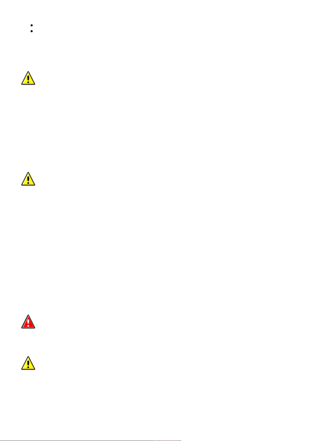
6
.
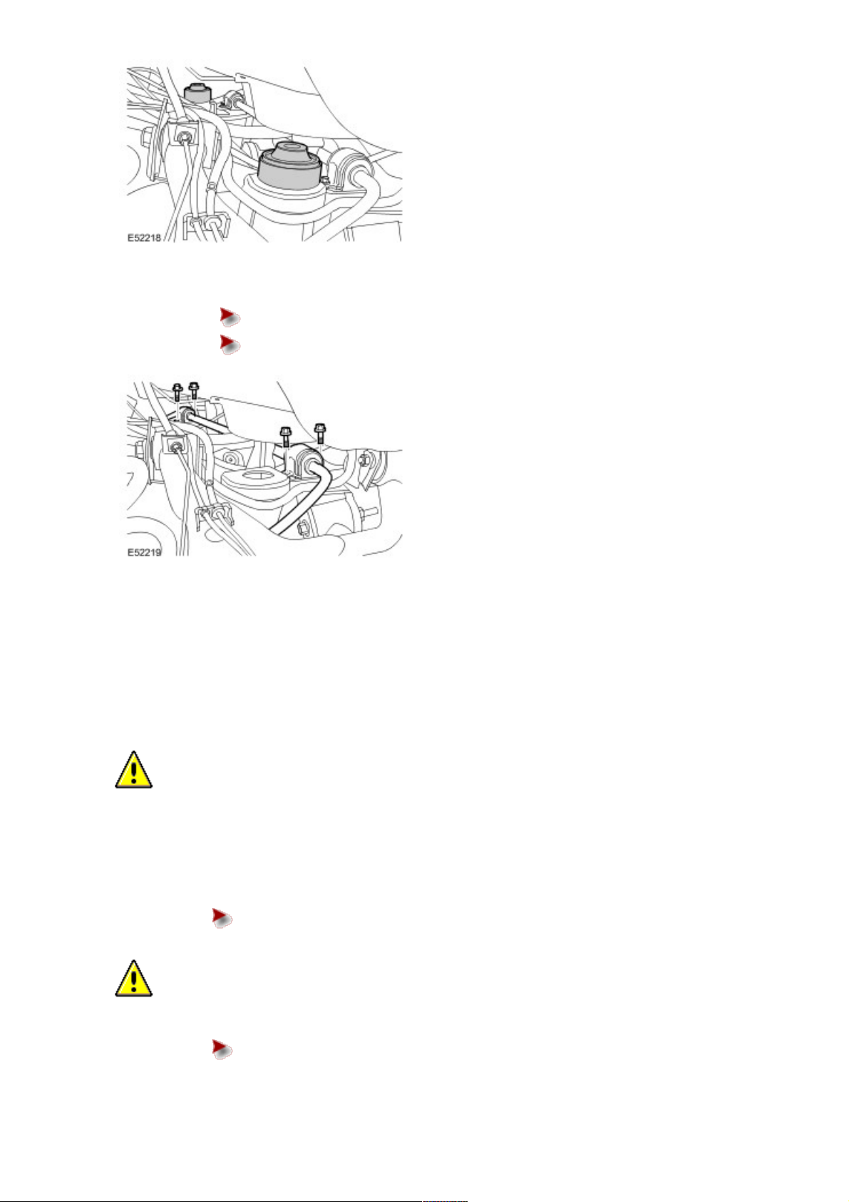
CAUTION: Before disconnecting or removing the components, ensure the area around the joint
faces and connections are clean. Plug open connections to prevent contamination.
CAUTION: Make sure the actuator fluid lines are not damaged or kinked during removal or
installation.
NOTE:
Some fluid spillage is inevitable during this operation.
Disconnect the fluid lines from the actuator.
Position container to collect fluid loss.
Remove the 2 bolts.
Remove and discard the plastic spacer washers.
Remove and discard the O-ring seals.
Install blanking caps to the exposed ports.
Page 27
07/16/2006 01:45 PMhttp://www.landrovertechinfo.com/extlrprod/frmviewit.jsp?szFrom=doc&iDocCode=276785
Page 2 of 4http://www.landrovertechinfo.com/extlrprod/frmviewit.jsp?szFrom=doc&iDocCode=276785
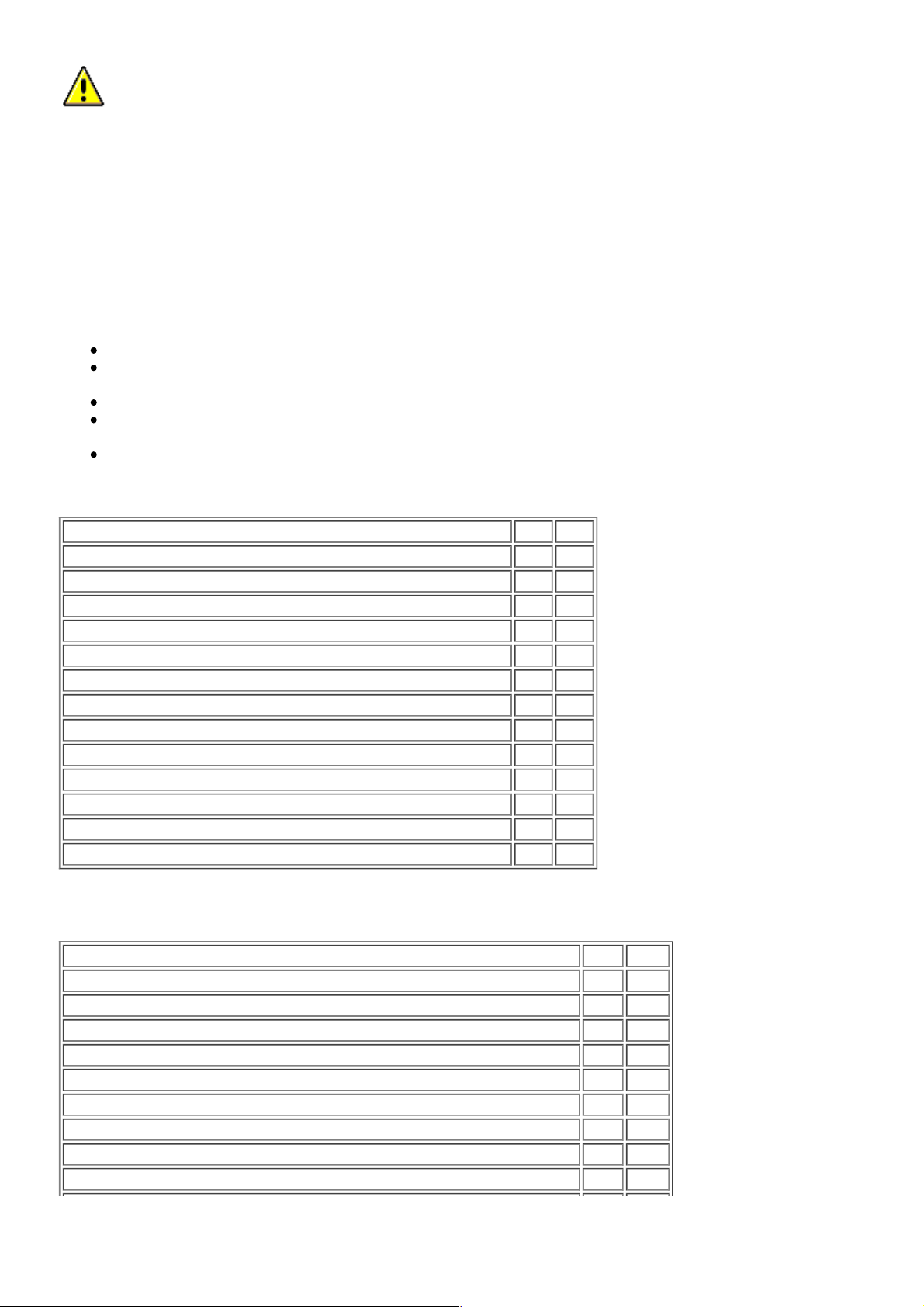
7 .
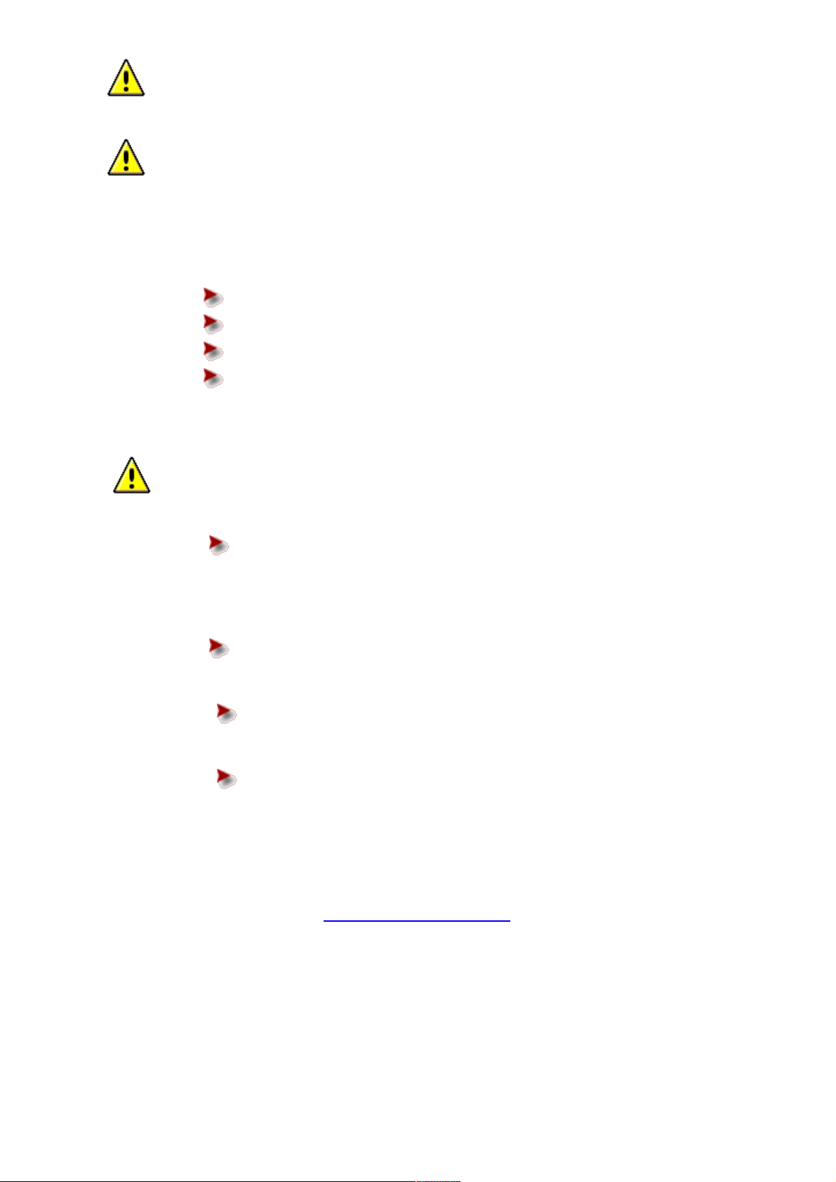
CAUTION: Use a wrench on the hexagon provided to prevent the ball joint rotating.
Release both stabilizer bar links.
Remove the 2 nuts.
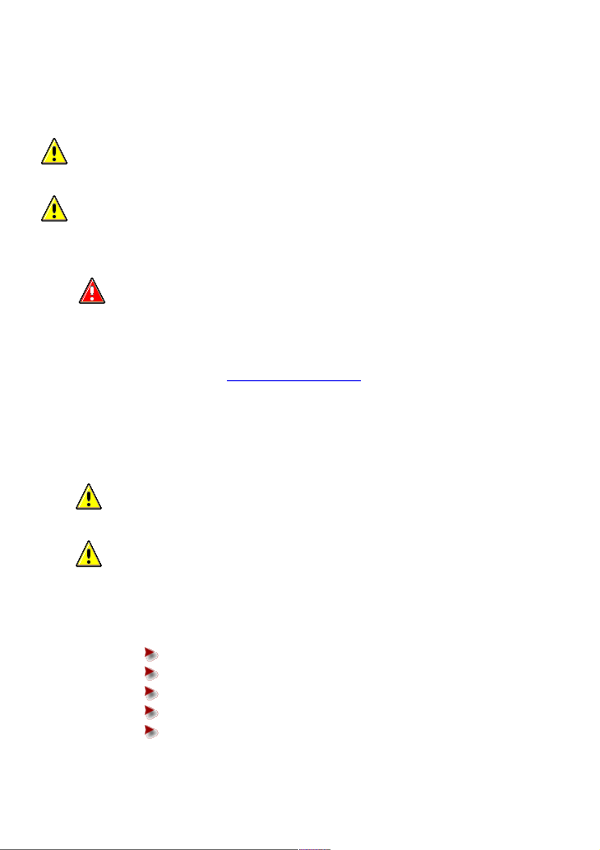
8 . Remove the body mount retaining bolts.
Remove the 8 bolts.
9 .
CAUTION: Only raise the body sufficiently to remove the body mount.
Raise the body.
Using suitable stands, raise the body to release the body mounts.
10 . Remove the 2 rear body mounts.
Page 28
07/16/2006 01:45 PMhttp://www.landrovertechinfo.com/extlrprod/frmviewit.jsp?szFrom=doc&iDocCode=276785
Page 3 of 4http://www.landrovertechinfo.com/extlrprod/frmviewit.jsp?szFrom=doc&iDocCode=276785
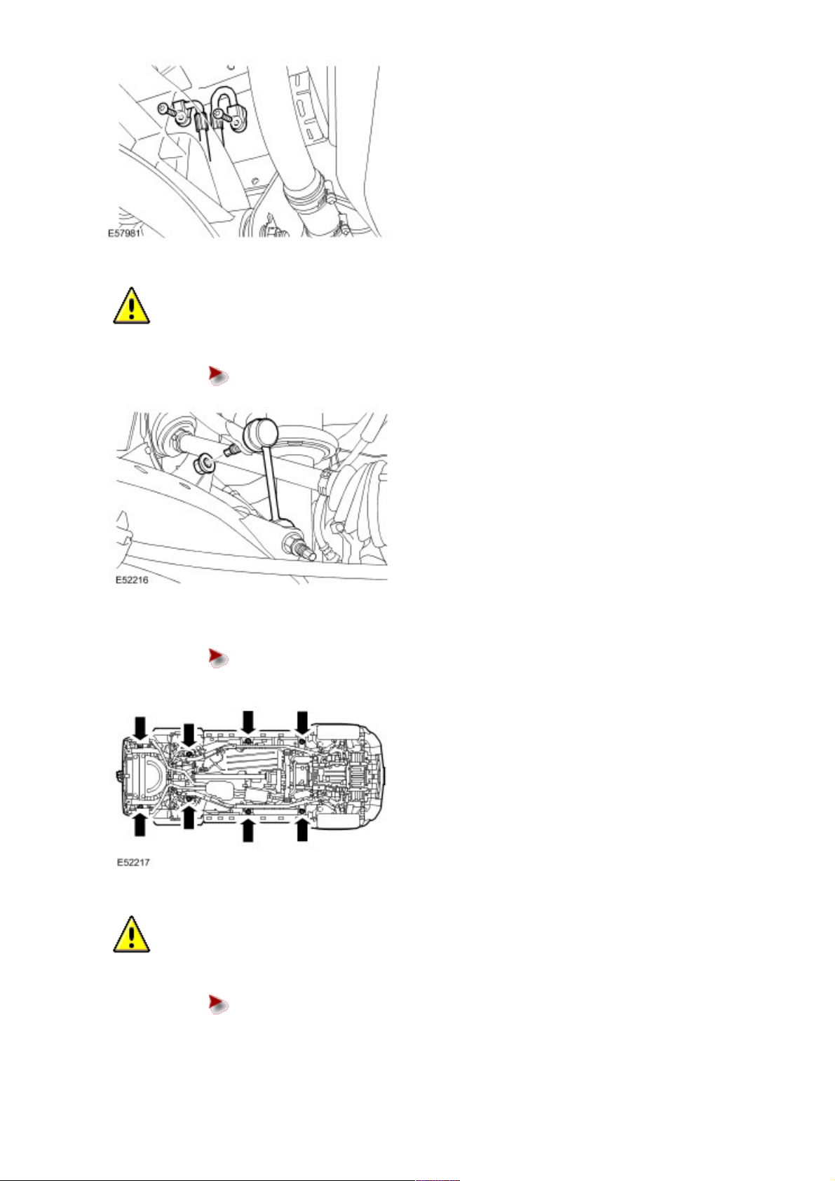
11 . Remove the stabilizer bar and actuator assembly bushings.
Remove the 4 bolts.
Remove the 2 clamps.
12 . NOTE:
Note the fitted position.
With assistance, remove the stabilizer bar and actuator assembly.
Installation
1 .
CAUTION: Make sure the stabilizer bar is correctly installed.
With assistance, install the stabilizer bar and actuator assembly.
2 . Install the stabilizer bar and actuator assembly bushings.
3 . Install the stabilizer bar clamps.
Tighten the 4 retaining bolts to 62 Nm (46 lb.ft).
4 .
CAUTION: Use a wrench on the hexagon provided to prevent the ball joint rotating.
Connect the RH stabilizer bar link.
Install a new nut and tighten to 115 Nm (85 lb.ft).
Page 29
07/16/2006 01:45 PMhttp://www.landrovertechinfo.com/extlrprod/frmviewit.jsp?szFrom=doc&iDocCode=276785
Page 4 of 4http://www.landrovertechinfo.com/extlrprod/frmviewit.jsp?szFrom=doc&iDocCode=276785
5
.
CAUTION: Make sure the actuator fluid lines are not damaged or kinked during removal or
installation.
CAUTION: Care must be taken to avoid damage to the plastic spacer washers and O-ring seals
during installation of the fluid lines to the actautor.
NOTE:
Some fluid spillage is inevitable during this operation.
Connect the fluid lines to the actuator.
Clean the component mating faces.
Remove the blanking caps from the ports.
Install new plastic spacer washers and O-ring seals.
Tighten the 2 bolts to 22 Nm (16 lb.ft).
6 . Bleed the rear of the Dynamic Response system using T4.
7 .
CAUTION: Use a wrench on the hexagon provided to prevent the ball joint rotating.
Connect the LH stabilizer bar link.
Install a new nut and tighten to 115 Nm (85 lb.ft).
8 . Install the body mounts.
9 . Lower the body.
Remove the stands.
10 . Install the body mount retaining bolts.
Tighten the 8 retaining bolts to 133 Nm (98 lb.ft).
11 . Install the wheels and tires.
Tighten the wheel nuts to 140 Nm (103 lb.ft).
12 . Lower the vehicle.
13 . Install the spare wheel and tire.
14 . Install the rear bumper cover.
For additional information, refer to Rear Bumper Cover (76.22.74)
Page 30
07/16/2006 01:45 PMhttp://www.landrovertechinfo.com/extlrprod/frmviewit.jsp?szFrom=doc&iDocCode=276785
Page 1 of 4http://www.landrovertechinfo.com/extlrprod/frmviewit.jsp?szFrom=doc&iDocCode=276785
Published: Jan 6, 2005
Front Stabilizer Bar (60.60.50)
Removal
CAUTION: Dynamic Response system components are manufactured to very precise tolerances. It is
therefore essential that absolute cleanliness is observed when working with these components. Always install
blanking plugs to any open orifices or lines. Failure to follow this instruction may result in foreign matter ingress
to the Dynamic Response system.
1
.
WARNING: Do not work on or under a vehicle supported only by a jack. Always support the vehicle
on safety stands.
Raise and support the vehicle.
2 . Remove the front wheels and tires.
3 . Remove the front driveshaft.
For additional information, refer to Front Driveshaft - 4.2L, Vehicles With: Supercharger (47.15.02)
4
.
CAUTION: Before disconnecting or removing the components, ensure the area around the joint
faces and connections are clean. Plug open connections to prevent contamination.
CAUTION: Make sure the actuator fluid lines are not damaged or kinked during removal or
installation.
NOTE:
Some fluid spillage is inevitable during this operation.
Disconnect the fluid lines from the actuator.
Position container to collect fluid loss.
Remove the 2 bolts.
Remove and discard the O-ring seals.
Remove and discard the plastic spacer washers.
Install blanking caps to the exposed ports.
Page 31

07/16/2006 01:45 PMhttp://www.landrovertechinfo.com/extlrprod/frmviewit.jsp?szFrom=doc&iDocCode=276785
Page 2 of 4http://www.landrovertechinfo.com/extlrprod/frmviewit.jsp?szFrom=doc&iDocCode=276785
5
.
CAUTION: Note the position of the hardened steel washer. The hardened steel washer must be
installed between the stabilizer bar link and the stabilizer bar. Failure to follow this instruction may result
in damage to the vehicle.
CAUTION: Use a Torx socket to prevent the ball joint rotating whilst removing the nut.
Disconnect both the stabilizer bar links from the stabilizer bar.
Remove and discard the 2 nuts.
6 . NOTE:
Left-hand shown, right-hand similar.
Remove the stabilizer bar bushings.
Remove the 6 bolts.
Remove the stabilizer bar clamps.
Page 32

07/16/2006 01:45 PMhttp://www.landrovertechinfo.com/extlrprod/frmviewit.jsp?szFrom=doc&iDocCode=276785
Page 3 of 4http://www.landrovertechinfo.com/extlrprod/frmviewit.jsp?szFrom=doc&iDocCode=276785
7
.
CAUTION: Make sure the actuator bleed nipple is not damaged when removing or installing the LH
stabilizer bar.
Remove the LH stabilizer bar from the Dynamic Response actuator.
Remove and discard the 6 bolts.
8 . Remove the RH stabilizer bar and Dynamic Response actuator assembly.
Installation
1 . Install the RH stabilizer bar and Dynamic Response actuator assembly.
2
.
CAUTION: Make sure the actuator bleed nipple is not damaged when removing or installing the LH
stabilizer bar.
Install the LH stabilizer bar to the Dynamic Response actuator.
Clean the component mating faces.
Install 6 new bolts and tighten to 120 Nm (89 lb.ft).
3 . Install the stabilizer bar bushings.
Clean the components.
Install the stabilizer bar clamps.
Install the 6 bolts.
Tighten the bolts to 115 Nm (85 lb.ft).
4
.
CAUTION: Make sure the hardened steel washer is installed between the stabilizer bar link and the
stabilizer bar. Failure to follow this instruction may result in damage to the vehicle.
CAUTION: Use a Torx socket to prevent the ball joint rotating whilst installing the nut.
Connect the LH stabilizer bar link.
Install a new nut and tighten to 175 Nm (129 lb.ft).
Page 33

07/16/2006 01:45 PMhttp://www.landrovertechinfo.com/extlrprod/frmviewit.jsp?szFrom=doc&iDocCode=276785
Page 4 of 4http://www.landrovertechinfo.com/extlrprod/frmviewit.jsp?szFrom=doc&iDocCode=276785
5
.
CAUTION: Make sure the actuator fluid lines are not damaged or kinked during removal or
installation.
CAUTION: Care must be taken to avoid damage to the plastic spacer washers and O-ring seals
during installation of the fluid lines to the actautor.
NOTE:
Some fluid spillage is inevitable during this operation.
Connect the fluid lines to the actuator.
Clean the component mating faces.
Remove the blanking caps from the ports.
Install new plastic spacer washers and O-ring seals.
Tighten the 2 bolts to 22 Nm (16 lb.ft).
6 . Bleed the front of the Dynamic Response system using T4.
7
.
CAUTION: Make sure the hardened steel washer is installed between the stabilizer bar link and the
stabilizer bar. Failure to follow this instruction may result in damage to the vehicle.
CAUTION: Use a Torx socket to prevent the ball joint rotating whilst installing the nut.
Connect the RH stabilizer bar link.
Install a new nut and tighten to 175 Nm (129 lb.ft).
8 . Install the front driveshaft.
For additional information, refer to Front Driveshaft - 4.2L, Vehicles With: Supercharger (47.15.02)
9 . Install the front wheels and tires.
Tighten the wheel nuts to 140 Nm (103 lb.ft).
Page 34

07/16/2006 01:44 PMhttp://www.landrovertechinfo.com/extlrprod/frmviewit.jsp?szFrom=doc&iDocCode=276785
Page 1 of 2http://www.landrovertechinfo.com/extlrprod/frmviewit.jsp?szFrom=doc&iDocCode=276785
Published: Jan 6, 2005
Rear Stabilizer Bar Bushing
Removal
1
.
WARNING: Do not work on or under a vehicle supported only by a jack. Always support the vehicle
on safety stands.
Raise and support the vehicle.
2 . Remove the rear bumper cover.
For additional information, refer to Rear Bumper Cover (76.22.74)
3 . Remove the spare wheel and tire.
4 . Raise the vehicle.
5 . Remove the rear wheels and tires.
6 . Remove the body mount retaining bolts.
Remove the 8 bolts.
7 .
CAUTION: Only raise the body sufficiently to remove the body mounts.
Raise the body.
Using suitable stands, raise the body to release the body mounts.
8 . Remove the 2 rear body mounts.
Page 35

07/16/2006 01:44 PMhttp://www.landrovertechinfo.com/extlrprod/frmviewit.jsp?szFrom=doc&iDocCode=276785
Page 2 of 2http://www.landrovertechinfo.com/extlrprod/frmviewit.jsp?szFrom=doc&iDocCode=276785
9 . Remove the stabilizer bar bushings.
Remove the 4 bolts.
Remove the 2 clamps.
Installation
1 . Install the stabilizer bar bushings.
2 . Install the stabilizer bar clamps.
Tighten the 4 retaining bolts to 62 Nm (46 lb.ft).
3 . Install the body mounts.
4 . Lower the body.
Remove the stands.
5 . Install the body mount retaining bolts.
Tighten the 8 retaining bolts to 133 Nm (98 lb.ft).
6 . Install the wheels and tires.
7 . Lower the vehicle.
8 . Install the spare wheel and tire.
9 . Install the rear bumper cover.
For additional information, refer to Rear Bumper Cover (76.22.74)
Page 36

07/16/2006 01:44 PMhttp://www.landrovertechinfo.com/extlrprod/frmviewit.jsp?szFrom=doc&iDocCode=276785
Page 1 of 2http://www.landrovertechinfo.com/extlrprod/frmviewit.jsp?szFrom=doc&iDocCode=276785
Published: Jan 6, 2005
Front Stabilizer Bar Bushing (60.60.47)
Removal
1
.
WARNING: Do not work on or under a vehicle supported only by a jack. Always support the vehicle
on safety stands.
Raise and support the vehicle.
2 . Remove the front wheels and tires.
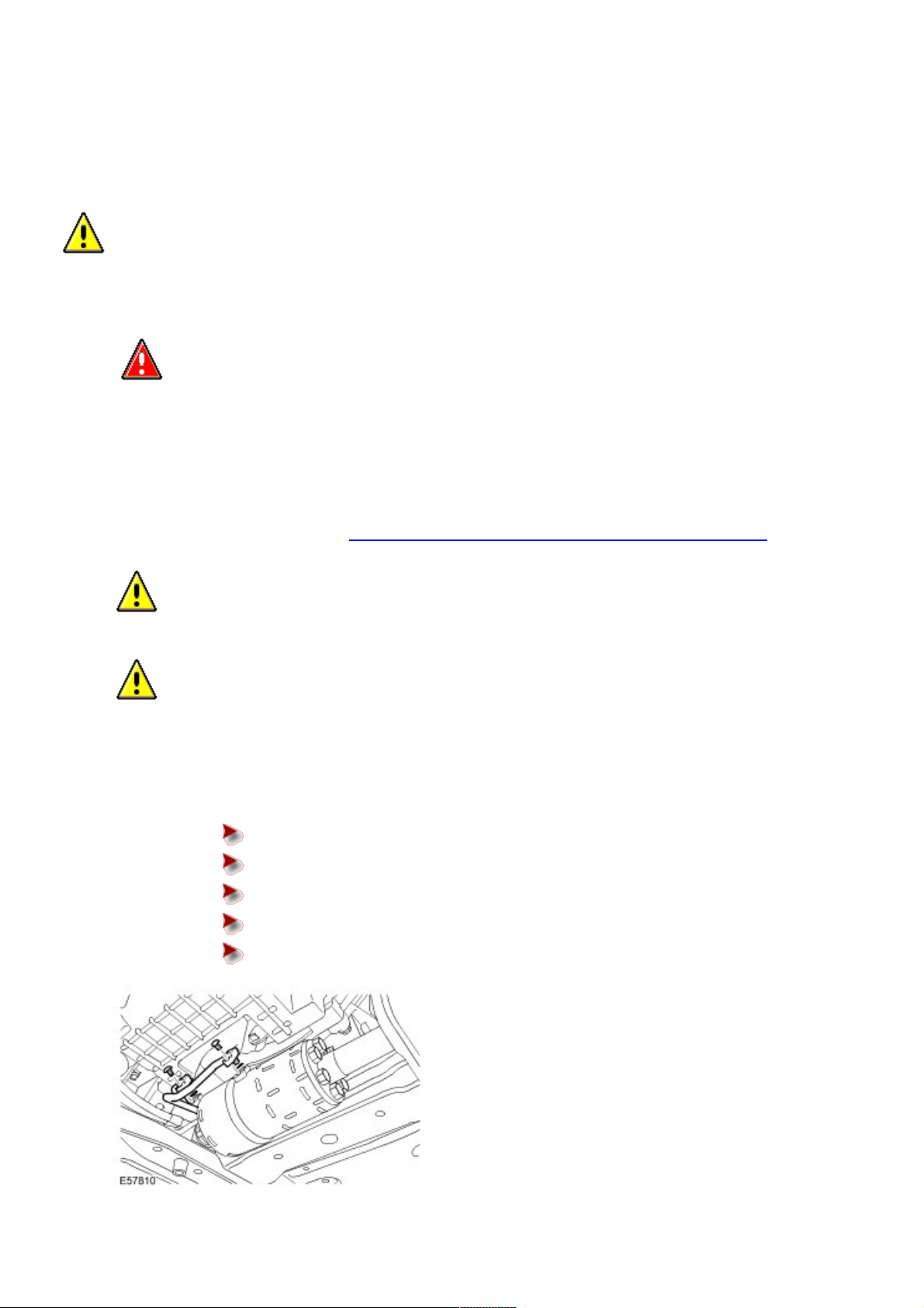
3
.
CAUTION: Use a Torx socket to prevent the ball joint rotating whilst removing the nut.
CAUTION: Note the position of the hardened steel washer. The hardened steel washer must be
installed between the stabilizer bar link and the stabilizer bar. Failure to follow this instruction may result
in damage to the vehicle.
Disconnect both stabilizer bar links from the stabilizer bar.
Remove and discard the 2 nuts.
4 . Remove the front driveshaft.
For additional information, refer to Front Driveshaft - 4.2L, Vehicles With: Supercharger (47.15.02)
5 . NOTE:
Left-hand shown, right-hand similar.
Remove the stabilizer bar bushings.
Remove the 6 bolts.
Remove the stabilizer bar clamps.
Page 37

07/16/2006 01:44 PMhttp://www.landrovertechinfo.com/extlrprod/frmviewit.jsp?szFrom=doc&iDocCode=276785
Page 2 of 2http://www.landrovertechinfo.com/extlrprod/frmviewit.jsp?szFrom=doc&iDocCode=276785
Installation
1 . Install the stabilizer bar bushings.
Clean the components.
Install the stabilizer bar clamps.
Install the 6 bolts.
Tighten the bolts to 115 Nm (85 lb.ft).
2 . Install the front driveshaft.
For additional information, refer to Front Driveshaft - 4.2L, Vehicles With: Supercharger (47.15.02)
3
.
CAUTION: Make sure the hardened steel washer is installed between the stabilizer bar link and the
stabilizer bar. Failure to follow this instruction may result in damage to the vehicle.
CAUTION: Use a Torx socket to prevent the ball joint rotating whilst installing the nut.
Connect both stabilizer bar links to the stabilizer bar.
Install new nuts and tighten to 175 Nm (129 lb.ft).
4 . Install the front wheels and tires.
Tighten the wheel nuts to 140 Nm (103 lb.ft).
Page 38

07/16/2006 01:43 PMhttp://www.landrovertechinfo.com/extlrprod/frmviewit.jsp?szFrom=doc&iDocCode=276785
Page 1 of 2http://www.landrovertechinfo.com/extlrprod/frmviewit.jsp?szFrom=doc&iDocCode=276785
Published: Jan 5, 2005
Valve Block Transducer (60.60.22)
Removal
CAUTION: Dynamic Response system components are manufactured to very precise tolerances and fine
clearances. It is therefore essential that absolute cleanliness is observed when working with these components.
Always install blanking plugs to any open orifices or lines. Failure to follow this instruction may result in foreign
matter ingress to the Dynamic Response system.
NOTE:
This procedure does not require the Dynamic Response system to be bled.
1
.
WARNING: Do not work on or under a vehicle supported only by a jack. Always support the vehicle
on safety stands.
Raise and support the vehicle.
2
.
CAUTION: Before disconnecting or removing the components, ensure the area around the joint
faces and connections are clean. Plug open connections to prevent contamination.
Remove the valve block transducer.
Disconnect the electrical connector.
Position container to collect fluid loss.
Installation
1 . Install the valve block transducer.
Clean the component mating faces.
Tighten to 25 Nm (18 lb.ft).
Remove the container.
2 . Start the engine and allow to idle.
3 . Check and top-up the Dynamic Response system fluid reservoir.
Page 39

07/16/2006 01:43 PMhttp://www.landrovertechinfo.com/extlrprod/frmviewit.jsp?szFrom=doc&iDocCode=276785
Page 2 of 2http://www.landrovertechinfo.com/extlrprod/frmviewit.jsp?szFrom=doc&iDocCode=276785
Page 40

07/16/2006 01:43 PMhttp://www.landrovertechinfo.com/extlrprod/frmviewit.jsp?szFrom=doc&iDocCode=276785
Page 1 of 5http://www.landrovertechinfo.com/extlrprod/frmviewit.jsp?szFrom=doc&iDocCode=276785
Published: Jan 5, 2005
Valve Block to Rear Stabilizer Bar Actuator Pipe Assembly
Removal
CAUTION: Dynamic Response system components are manufactured to very precise tolerances. It is
therefore essential that absolute cleanliness is observed when working with these components. Always install
blanking plugs to any open orifices or lines. Failure to follow this instruction may result in foreign matter ingress
to the Dynamic Response system.
NOTE:
The valve block seals do not require replacement unless there is evidence of a fluid leak.
1
.
WARNING: Do not work on or under a vehicle supported only by a jack. Always support the vehicle
on safety stands.
Raise and support the vehicle.
2 . Remove the rear bumper cover.
For additional information, refer to Rear Bumper Cover (76.22.74)
3 . Remove the spare wheel and tire.
4 . Remove the rear wheels and tires.
5 . Remove the body mount retaining bolts.
Remove the 8 bolts.
6
.
CAUTION: Only raise the body sufficiently to remove the valve block to rear stabilizer bar actuator
pipe.
Using suitable stands, raise the body.
7 . Release the valve block to rear stabilizer bar actuator pipe assembly mounting.
Remove the nut.
Page 41

07/16/2006 01:43 PMhttp://www.landrovertechinfo.com/extlrprod/frmviewit.jsp?szFrom=doc&iDocCode=276785
Page 2 of 5http://www.landrovertechinfo.com/extlrprod/frmviewit.jsp?szFrom=doc&iDocCode=276785
8 . Release the valve block to rear stabilizer bar actuator pipe assembly mounting.
Remove the nut.
Remove the bolt.
Remove the bracket.
9
.
CAUTION: Before disconnecting or removing the components, ensure the area around the joint
faces and connections are clean. Plug open connections to prevent contamination.
CAUTION: Make sure the actuator fluid lines are not damaged or kinked during removal or
installation.
NOTE:
Some fluid spillage is inevitable during this operation.
Disconnect the fluid lines from the actuator.
Position container to collect fluid loss.
Remove the 2 bolts.
Remove and discard the O-ring seals.
Remove and discard the plastic spacer washers.
Install blanking caps to the exposed ports.
Page 42

07/16/2006 01:43 PMhttp://www.landrovertechinfo.com/extlrprod/frmviewit.jsp?szFrom=doc&iDocCode=276785
Page 3 of 5http://www.landrovertechinfo.com/extlrprod/frmviewit.jsp?szFrom=doc&iDocCode=276785
10
.
CAUTION: Before disconnecting or removing the components, ensure the area around the joint
faces and connections are clean. Plug open connections to prevent contamination.
NOTE:
Some fluid spillage is inevitable during this operation.
Disconnect the rear actuator pipes from the valve block.
Position a container to collect the fluid spillage.
Remove and discard the nut.
11 . Remove the valve block to rear stabilizer bar actuator pipe assembly.
Installation
1 . Check the valve block O-rings and plastic spacer washers are correctly installed.
A: Backing rings (white)
B: Outer clamping ring
C: O-ring seals
D: Outer backing ring (Black)
Page 43

07/16/2006 01:43 PMhttp://www.landrovertechinfo.com/extlrprod/frmviewit.jsp?szFrom=doc&iDocCode=276785
Page 4 of 5http://www.landrovertechinfo.com/extlrprod/frmviewit.jsp?szFrom=doc&iDocCode=276785
2
.
CAUTION: Make sure the actuator fluid lines are not damaged or kinked during removal or
installation.
Install the valve block to rear stabilizer bar actuator pipe assembly.
3 . NOTE:
Some fluid spillage is inevitable during this operation.
Connect the rear actuator pipes to the valve block.
Remove the blanking caps from the ports.
Install a new nut and tighten to 22 Nm (16 lb.ft).
Remove the container.
4
.
CAUTION: Make sure the actuator fluid lines are not damaged or kinked during removal or
installation.
CAUTION: Care must be taken to avoid damage to the plastic spacer washers and O-ring seals
during installation of the fluid lines to the actuator.
NOTE:
Some fluid spillage is inevitable during this operation.
Connect the fluid lines to the actuator.
Clean the component mating faces.
Remove the blanking caps from the ports.
Install new plastic spacer washers and O-ring seals.
Tighten the 2 bolts to 22 Nm (16 lb.ft).
5 . Secure the valve block to rear stabilizer bar actuator pipe assembly mounting.
Install the bracket.
Install the nut and bolt and tighten to 9 Nm (7 lb.ft).
Page 44

07/16/2006 01:43 PMhttp://www.landrovertechinfo.com/extlrprod/frmviewit.jsp?szFrom=doc&iDocCode=276785
Page 5 of 5http://www.landrovertechinfo.com/extlrprod/frmviewit.jsp?szFrom=doc&iDocCode=276785
6 . Secure the valve block to rear stabilizer bar actuator pipe assembly mounting.
Tighten the nut to 9 Nm (7 lb.ft)
7 . Bleed the rear of the Dynamic Response system using T4.
For additional information, refer to Active Stabilization System Bleeding (60.60.13)
8 . Lower the body.
Remove the stands.
9 . Install the body mount retaining bolts.
Tighten the 8 retaining bolts to 133 Nm (98 lb.ft).
10 . Install the wheels and tires.
Tighten the wheel nuts to 140 Nm (103 lb.ft).
11 . Install the spare wheel and tire.
12 . Install the rear bumper cover.
For additional information, refer to Rear Bumper Cover (76.22.74)
Page 45

07/16/2006 01:42 PMhttp://www.landrovertechinfo.com/extlrprod/frmviewit.jsp?szFrom=doc&iDocCode=276785
Page 1 of 9http://www.landrovertechinfo.com/extlrprod/frmviewit.jsp?szFrom=doc&iDocCode=276785
Published: Jan 20, 2005
Valve Block to Front Stabilizer Bar Actuator Pipe Assembly
Special Service Tools
Ball joint separator
205-754 (LRT-54-027)
Removal
CAUTION: Dynamic Response system components are manufactured to very precise tolerances. It is
therefore essential that absolute cleanliness is observed when working with these components. Always install
blanking plugs to any open orifices or lines. Failure to follow this instruction may result in foreign matter ingress
to the Dynamic Response system.
1
.
WARNING: Do not work on or under a vehicle supported only by a jack. Always support the vehicle
on safety stands.
Raise and support the vehicle.
2 . Remove the rear bumper cover.
For additional information, refer to Rear Bumper Cover (76.22.74)
3 . Remove the spare wheel and tire.
4 . Remove the engine undershield.
For additional information, refer to Engine Undershield (76.10.50)
5
.
CAUTION: Before disconnecting or removing the components, ensure the area around the joint
faces and connections are clean. Plug open connections to prevent contamination.
CAUTION: Make sure the actuator fluid lines are not damaged or kinked during removal or
installation.
NOTE:
Some fluid spillage is inevitable during this operation.
Disconnect the fluid lines from the actuator.
Position container to collect fluid loss.
Remove the 2 bolts.
Page 46

07/16/2006 01:42 PMhttp://www.landrovertechinfo.com/extlrprod/frmviewit.jsp?szFrom=doc&iDocCode=276785
Page 2 of 9http://www.landrovertechinfo.com/extlrprod/frmviewit.jsp?szFrom=doc&iDocCode=276785
Remove and discard the O-ring seals.
Remove and discard the plastic spacer washers.
Install blanking caps to the exposed ports.
6 . Remove the front wheels and tires.
7 . RH front: Remove the shock absorber and air spring assembly.
For additional information, refer to Front Shock Absorber and Air Spring Assembly (60.21.01.99)
8 . Release the brake hose bracket from the wheel knuckle.
Remove the retaining bolt.
9 .
CAUTION: Do not allow the brake caliper to hang on the brake hose.
Release the brake caliper from the wheel knuckle.
Remove the 2 retaining bolts.
Tie the brake caliper aside.
Page 47

07/16/2006 01:42 PMhttp://www.landrovertechinfo.com/extlrprod/frmviewit.jsp?szFrom=doc&iDocCode=276785
Page 3 of 9http://www.landrovertechinfo.com/extlrprod/frmviewit.jsp?szFrom=doc&iDocCode=276785
10 . NOTE:
The brake disc is shown removed for clarity.
Release the wheel speed sensor from the wheel knuckle.
Remove the bolt.
11
.
CAUTION: Note the position of the hardened steel washer. The hardened steel washer must be
installed between the stabilizer bar link and the upper arm. Failure to follow this instruction may result in
damage to the vehicle.
CAUTION: Use a Torx socket to prevent the ball joint rotating whilst removing the nut.
Remove the stabilizer bar link nut.
Discard the nut.
12
.
CAUTION: To prevent the wheel knuckle falling outwards and disconnection of the halfshaft inner
joint, support the wheel knuckle.
Loosen the upper arm retaining nut.
13 . Using the special tool, release the upper arm ball joint.
Remove and discard the retaining nut.
14 . Remove the integrated body frame bracket.
Page 48
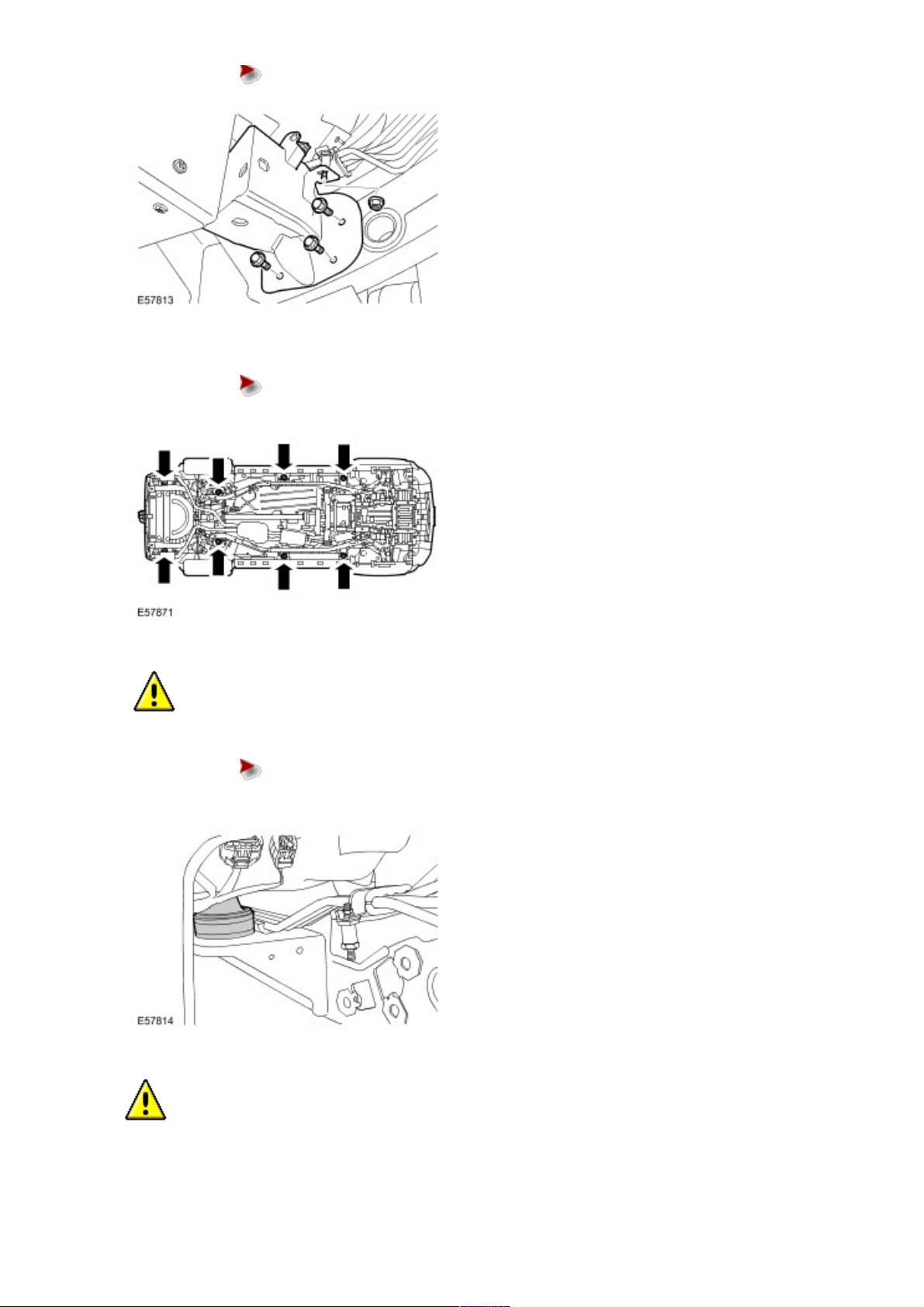
07/16/2006 01:42 PMhttp://www.landrovertechinfo.com/extlrprod/frmviewit.jsp?szFrom=doc&iDocCode=276785
Page 4 of 9http://www.landrovertechinfo.com/extlrprod/frmviewit.jsp?szFrom=doc&iDocCode=276785
Remove the 3 bolts and 1 nut.
15 . Remove the body mount retaining bolts.
Remove the 8 bolts.
16 .
CAUTION: Only raise the body sufficiently to remove the body mount.
Raise the body.
Using suitable stands, raise the body to release the body mounts.
17 . Remove the body mount.
18
.
CAUTION: Before disconnecting or removing the components, ensure the area around the joint
faces and connections are clean. Plug open connections to prevent contamination.
NOTE:
Some fluid spillage is inevitable during this operation.
Page 49

07/16/2006 01:42 PMhttp://www.landrovertechinfo.com/extlrprod/frmviewit.jsp?szFrom=doc&iDocCode=276785
Page 5 of 9http://www.landrovertechinfo.com/extlrprod/frmviewit.jsp?szFrom=doc&iDocCode=276785
Disconnect the high pressure line.
Position a container to collect the fluid spillage.
Install blanking caps to the exposed ports.
19 . Remove the air cleaner assembly.
For additional information, refer to Air Cleaner (19.10.01)
20
.
CAUTION: Before disconnecting or removing the components, ensure the area around the joint
faces and connections are clean. Plug open connections to prevent contamination.
NOTE:
Some fluid spillage is inevitable during this operation.
Disconnect the fluid return line from the reservoir.
Position a container to collect the fluid spillage.
Reposition the fluid line into the wheel arch area.
21 . Release the valve block to front stabilizer bar actuator pipe assembly mountings.
Remove the 2 nuts and 1 bolt.
Page 50

07/16/2006 01:42 PMhttp://www.landrovertechinfo.com/extlrprod/frmviewit.jsp?szFrom=doc&iDocCode=276785
Page 6 of 9http://www.landrovertechinfo.com/extlrprod/frmviewit.jsp?szFrom=doc&iDocCode=276785
22
.
CAUTION: Always plug any open connections to prevent contamination.
CAUTION: Before disconnecting or removing the components, ensure the area around the joint
faces and connections are clean. Plug open connections to prevent contamination.
NOTE:
Some fluid spillage is inevitable during this operation.
Disconnect the front actuator pipes from the valve block.
Position a container to collect the fluid spillage.
Remove and discard the 2 nuts.
Install blanking caps to the exposed ports.
23 . Remove the valve block to front stabilizer bar actuator pipe assembly.
Installation
1 . Check the valve block O-rings and plastic spacer washers are correctly installed.
A: Backing rings (white)
B: Outer clamping ring
C: O-ring seals
Page 51

07/16/2006 01:42 PMhttp://www.landrovertechinfo.com/extlrprod/frmviewit.jsp?szFrom=doc&iDocCode=276785
Page 7 of 9http://www.landrovertechinfo.com/extlrprod/frmviewit.jsp?szFrom=doc&iDocCode=276785
D: Outer backing ring (Black)
2 . Install the valve block to front stabilizer bar actuator pipe assembly.
Clean the components.
3 . Connect the front actuator pipes to the valve block.
Remove the blanking caps from the ports.
Install 2 new nuts and tighten to 22 Nm (16 lb.ft).
Remove the container.
4 . Attach the valve block to front stabilizer bar actuator pipe assembly mountings.
Tighten the 2 nuts and 1 bolt to 9 Nm (7 lb.ft).
5 . Connect the fluid line to the reservoir.
Reposition the fluid line from the wheel arch area.
Install the clip.
Remove the container.
6 . Install the air cleaner assembly.
For additional information, refer to Air Cleaner (19.10.01)
7 . Connect the high pressure line.
Remove the blanking caps from the ports.
Tighten the union to 21 Nm (15 lb.ft).
Remove the container.
8 . Install the body mount.
9 . Lower the body.
Remove the stands.
10 . Install the body mount retaining bolts.
Tighten the 8 retaining bolts to 133 Nm (98 lb.ft).
11 . Install the integrated body frame bracket.
Install the 3 bolts and tighten to 40 Nm (30 lb.ft).
Page 52

07/16/2006 01:42 PMhttp://www.landrovertechinfo.com/extlrprod/frmviewit.jsp?szFrom=doc&iDocCode=276785
Page 8 of 9http://www.landrovertechinfo.com/extlrprod/frmviewit.jsp?szFrom=doc&iDocCode=276785
Tighten the nut to 9 Nm (7 lb.ft)
12 . Connect the upper arm and wheel knuckle.
Install a new nut and tighten to 70 Nm (52 lb.ft).
13 . Install the wheel speed sensor.
Tighten the bolt to 9 Nm (7 lb.ft).
Connect the electrical connector.
Secure the wiring harness in the clips.
14 . Secure the brake caliper to the wheel knuckle.
Tighten the bolts to 275 Nm (203 lb.ft).
15 . Secure the brake hose retaining bracket to the wheel knuckle.
Tighten the bolt to 23 Nm (17 lb.ft).
16 . Install the shock absorber and air spring assembly.
For additional information, refer to Front Shock Absorber and Air Spring Assembly (60.21.01.99)
17
.
CAUTION: Make sure the actuator fluid lines are not damaged or kinked during removal or
installation.
CAUTION: Care must be taken to avoid damage to the plastic spacer washers and O-ring seals
during installation of the fluid lines to the actautor.
NOTE:
Some fluid spillage is inevitable during this operation.
Connect the fluid lines to the actuator.
Clean the component mating faces.
Remove the blanking caps from the ports.
Install new plastic spacer washers and O-ring seals.
Tighten the 2 bolts to 22 Nm (16 lb.ft).
18 . Bleed the front of the Dynamic Response system using T4.
19 . Install the engine undershield.
For additional information, refer to Engine Undershield (76.10.50)
20
.
CAUTION: Make sure the hardened steel washer is installed between the stabilizer bar link and the
upper arm. Failure to follow this instruction may result in damage to the vehicle.
CAUTION: Use a Torx socket to prevent the ball joint rotating whilst installing the nut.
Secure the stabilizer bar link.
Page 53

07/16/2006 01:42 PMhttp://www.landrovertechinfo.com/extlrprod/frmviewit.jsp?szFrom=doc&iDocCode=276785
Page 9 of 9http://www.landrovertechinfo.com/extlrprod/frmviewit.jsp?szFrom=doc&iDocCode=276785
Install a new nut and tighten to 175 Nm (129 lb.ft).
21 . Install the front wheels and tires.
Tighten the wheel nuts to 140 Nm (103 lb.ft).
22 . Install the spare wheel and tire.
23 . Install the rear bumper cover.
For additional information, refer to Rear Bumper Cover (76.22.74)
Page 54

07/16/2006 01:42 PMhttp://www.landrovertechinfo.com/extlrprod/frmviewit.jsp?szFrom=doc&iDocCode=276785
Page 1 of 2http://www.landrovertechinfo.com/extlrprod/frmviewit.jsp?szFrom=doc&iDocCode=276785
Published: Jan 5, 2005
Valve Block Filter (60.60.21)
Removal
CAUTION: Dynamic Response system components are manufactured to very precise tolerances and fine
clearances. It is therefore essential that absolute cleanliness is observed when working with these components.
Always install blanking plugs to any open orifices or lines. Failure to follow this instruction may result in foreign
matter ingress to the Dynamic Response system.
NOTE:
This procedure does not require the Dynamic Response system to be bled.
1
.
WARNING: Do not work on or under a vehicle supported only by a jack. Always support the vehicle
on safety stands.
Raise and support the vehicle.
2
.
CAUTION: Before disconnecting or removing the components, ensure the area around the joint
faces and connections are clean. Plug open connections to prevent contamination.
Remove and discard the valve block filter.
Position container to collect fluid loss.
Remove the access plug.
Remove and discard the access plug O-ring seal.
Using a suitable M6 bolt, release the filter from the valve block.
Installation
1 . Install the new valve block filter.
Clean the component mating faces.
Install a new access plug O-ring seal.
Tighten the access plug to 62 Nm (46 lb.ft).
Remove the container.
Page 55

07/16/2006 01:42 PMhttp://www.landrovertechinfo.com/extlrprod/frmviewit.jsp?szFrom=doc&iDocCode=276785
Page 2 of 2http://www.landrovertechinfo.com/extlrprod/frmviewit.jsp?szFrom=doc&iDocCode=276785
2 . Start the engine and allow to idle.
3 . Check and top-up the Dynamic Response system fluid reservoir.
Page 56

07/16/2006 01:41 PMhttp://www.landrovertechinfo.com/extlrprod/frmviewit.jsp?szFrom=doc&iDocCode=276785
Page 1 of 5http://www.landrovertechinfo.com/extlrprod/frmviewit.jsp?szFrom=doc&iDocCode=276785
Published: Jan 5, 2005
Valve Block (60.60.20)
Removal
CAUTION: Dynamic Response system components are manufactured to very precise tolerances and fine
clearances. It is therefore essential that absolute cleanliness is observed when working with these components.
Always install blanking plugs to any open orifices or lines. Failure to follow this instruction may result in foreign
matter ingress to the Dynamic Response system.
NOTE:
The valve block seals do not require replacement unless there is evidence of a fluid leak. A new valve block is
supplied with new seals installed.
1
.
WARNING: Do not work on or under a vehicle supported only by a jack. Always support the vehicle
on safety stands.
Raise and support the vehicle.
2 . NOTE:
Some fluid spillage is inevitable during this operation.
Release the front actuator pipes from the valve block.
Position a container to collect the fluid spillage.
Remove and discard the 2 nuts.
3 . Release the valve block to rear stabilizer bar actuator pipe assembly mounting.
Remove the nut.
Page 57

07/16/2006 01:41 PMhttp://www.landrovertechinfo.com/extlrprod/frmviewit.jsp?szFrom=doc&iDocCode=276785
Page 2 of 5http://www.landrovertechinfo.com/extlrprod/frmviewit.jsp?szFrom=doc&iDocCode=276785
4 . Release the valve block to rear stabilizer bar actuator pipe assembly mounting.
Remove the bolt.
Remove the nut.
Remove the bracket.
5
.
CAUTION: Before disconnecting or removing the components, ensure the area around the joint
faces and connections are clean. Plug open connections to prevent contamination.
NOTE:
Some fluid spillage is inevitable during this operation.
Disconnect the rear actuator pipes from the valve block.
Position a container to collect the fluid spillage.
Remove and discard the nut.
Page 58

07/16/2006 01:41 PMhttp://www.landrovertechinfo.com/extlrprod/frmviewit.jsp?szFrom=doc&iDocCode=276785
Page 3 of 5http://www.landrovertechinfo.com/extlrprod/frmviewit.jsp?szFrom=doc&iDocCode=276785
6
.
CAUTION: Before disconnecting or removing the components, ensure the area around the joint
faces and connections are clean. Plug open connections to prevent contamination.
CAUTION: Make sure the actuator fluid lines are not clamped or kinked. Failure to follow this
instruction will result in damage to the vehicle.
NOTE:
Some fluid spillage is inevitable during this operation.
NOTE:
Note the fitted position of the washers.
Remove the valve block.
Disconnect the 4 electrical connectors.
Remove the 3 bolts.
Collect the 4 washers.
Disconnect the front actuator pipes from the valve block.
Installation
1 . Check the valve block O-rings seals and plastic spacer washers are correctly installed.
A: Backing rings (white)
B: Outer clamping ring
C: O-ring seals
D: Outer backing ring (Black)
Page 59

07/16/2006 01:41 PMhttp://www.landrovertechinfo.com/extlrprod/frmviewit.jsp?szFrom=doc&iDocCode=276785
Page 4 of 5http://www.landrovertechinfo.com/extlrprod/frmviewit.jsp?szFrom=doc&iDocCode=276785
2.NOTE:
Make sure there are two washers installed between the integrated body frame and the valve block lower
retaining bolt.
Install the valve block.
Remove the blanking caps from the ports.
Connect the front actuator pipes to the valve block.
Install 2 new nuts and tighten to 22 Nm (16 lb.ft).
Install the 3 valve block retaining bolts, and tighten to 22 Nm (16 lb.ft).
Connect the electrical connectors.
3 . Connect the rear actuator pipes to the valve block.
Remove the blanking caps from the ports.
Install a new nut and tighten to 22 Nm (16 lb.ft).
Remove the container.
4 . Secure the valve block to rear stabilizer bar actuator pipe assembly mounting.
Install the bracket.
Install the nut and bolt and tighten to 9 Nm (7 lb.ft).
Page 60

07/16/2006 01:41 PMhttp://www.landrovertechinfo.com/extlrprod/frmviewit.jsp?szFrom=doc&iDocCode=276785
Page 5 of 5http://www.landrovertechinfo.com/extlrprod/frmviewit.jsp?szFrom=doc&iDocCode=276785
5 . Secure the valve block to rear stabilizer bar actuator pipe assembly mountings.
Tighten the nut to 9 Nm (7 lb.ft)
6 . Using T4, bleed the Dynamic Response system.
Page 61

07/16/2006 01:41 PMhttp://www.landrovertechinfo.com/extlrprod/frmviewit.jsp?szFrom=doc&iDocCode=276785
Page 1 of 2http://www.landrovertechinfo.com/extlrprod/frmviewit.jsp?szFrom=doc&iDocCode=276785
Published: Jan 5, 2005
Dynamic Response Module (60.60.01)
Removal
NOTE:
The dynamic response module is always located on the driver's side of the vehicle.
1 . Remove the cowl side trim panel.
For additional information, refer to Cowl Side Trim Panel (76.13.27)
2 . Remove the closing trim panel.
Release the clip.
Remove the 2 screws.
Disconnect the electrical connector.
3 . Remove the dynamic response module.
Remove the 2 bolts.
Disconnect the 2 electrical connectors.
Page 62

07/16/2006 01:41 PMhttp://www.landrovertechinfo.com/extlrprod/frmviewit.jsp?szFrom=doc&iDocCode=276785
Page 2 of 2http://www.landrovertechinfo.com/extlrprod/frmviewit.jsp?szFrom=doc&iDocCode=276785
Installation
1 . Install the dynamic response module.
Connect the electrical connectors.
Tighten the 2 bolts to 4 Nm (3 lb.ft).
2 . Install the closing trim panel.
Connect the electrical connector.
Secure the clip.
Tighten the screws.
3 . Install the cowl side trim panel.
For additional information, refer to Cowl Side Trim Panel (76.13.27)
4 . Initiate a new control module using T4.
Page 63

07/16/2006 01:40 PMhttp://www.landrovertechinfo.com/extlrprod/frmviewit.jsp?szFrom=doc&iDocCode=276785
Page 1 of 4http://www.landrovertechinfo.com/extlrprod/frmviewit.jsp?szFrom=doc&iDocCode=276785
Published: Feb 9, 2005
Fluid Pump - 2.7L (TdV6) Diesel (60.60.10)
Removal
CAUTION: Dynamic Response system components are manufactured to very precise tolerances. It is
therefore essential that absolute cleanliness is observed when working with these components. Always install
blanking plugs to any open orifices or lines. Failure to follow this instruction may result in foreign matter ingress
to the dynamic response system.
1 . Disconnect the battery ground cable.
For additional information, refer to Specifications
2
.
WARNING: Do not work on or under a vehicle supported only by a jack. Always support the vehicle
on safety stands.
Raise and support the vehicle.
3 . Remove the front RH splash shield.
Remove the 4 clips.
4 . Remove the engine undershield.
For additional information, refer to Engine Undershield (76.10.50)
5 . Remove the radiator access panel.
Remove the 4 bolts.
Page 64

07/16/2006 01:40 PMhttp://www.landrovertechinfo.com/extlrprod/frmviewit.jsp?szFrom=doc&iDocCode=276785
Page 2 of 4http://www.landrovertechinfo.com/extlrprod/frmviewit.jsp?szFrom=doc&iDocCode=276785
6 . Remove the front RH fender splash shield.
For additional information, refer to Fender Splash Shield (76.10.48)
7 . NOTE:
Loosen the bolts prior to removing the accessory drive belt.
Loosen the fluid pump drive pulley retaining bolts.
Loosen the 3 Torx bolts.
8 . Release the tension from the belt.
Remove the accessory drive belt.
9 . Remove the fluid pump drive pulley.
Remove the 3 bolts.
10
.
CAUTION: Before disconnecting or removing the components, ensure the area around the joint
faces and connections are clean. Plug open connections to prevent contamination.
NOTE:
Some fluid spillage is inevitable during this operation.
Disconnect the fluid pump hoses.
Clamp the fluid pump to reservoir hose.
Release the hose clip.
Disconnect the hoses.
Discard the O-ring seals.
Page 65

07/16/2006 01:40 PMhttp://www.landrovertechinfo.com/extlrprod/frmviewit.jsp?szFrom=doc&iDocCode=276785
Page 3 of 4http://www.landrovertechinfo.com/extlrprod/frmviewit.jsp?szFrom=doc&iDocCode=276785
11 . Remove the fluid pump.
Remove the 3 bolts.
Installation
1 . Install the fluid pump.
Clean the locating dowels.
Install and tighten the bolts to 22 Nm (16 lb.ft).
Prime the pump with clean fluid.
2 .
CAUTION: Make sure both O-ring seals are correctly installed on the high pressure union.
Connect the hoses.
Clean the component mating faces.
Lubricate and install new O-rings to the high-pressure union.
Page 66

07/16/2006 01:40 PMhttp://www.landrovertechinfo.com/extlrprod/frmviewit.jsp?szFrom=doc&iDocCode=276785
Page 4 of 4http://www.landrovertechinfo.com/extlrprod/frmviewit.jsp?szFrom=doc&iDocCode=276785
Tighten the union to 35 Nm (26 lb.ft).
Install the hose clip.
Remove the hose clamp.
3 . Install the fluid pump drive pulley.
Install the Torx bolts, but do not tighten fully at this stage.
4 . Install the belt.
5 . Tighten the fluid pump drive pulley retaining bolts to 22 Nm (16 lb.ft).
6 . Install the fender splash shield.
For additional information, refer to Fender Splash Shield (76.10.48)
7 . Install the radiator access panel.
Tighten the 4 bolts to 10 Nm (7 lb.ft).
8 . Install the engine undershield.
For additional information, refer to Engine Undershield (76.10.50)
9 . Install the front RH splash shield.
10 . Refill the fluid reservoir.
11 . Connect the battery ground lead, tighten the nut to 5 Nm (4 lb.ft).
For additional information, refer to Specifications
12 . Make sure there is fluid circulation through the reservoir.
Start the engine and allow to idle.
Page 67

07/16/2006 01:40 PMhttp://www.landrovertechinfo.com/extlrprod/frmviewit.jsp?szFrom=doc&iDocCode=276785
Page 1 of 3http://www.landrovertechinfo.com/extlrprod/frmviewit.jsp?szFrom=doc&iDocCode=276785
Published: Feb 9, 2005
Fluid Pump - 4.2L/4.4L (60.60.10)
Removal
CAUTION: Dynamic Response system components are manufactured to very precise tolerances. It is
therefore essential that absolute cleanliness is observed when working with these components. Always install
blanking plugs to any open orifices or lines. Failure to follow this instruction may result in foreign matter ingress
to the dynamic response system.
1 . Disconnect the battery ground cable.
For additional information, refer to Specifications
2
.
WARNING: Do not work on or under a vehicle supported only by a jack. Always support the vehicle
on safety stands.
Raise and support the vehicle.
3 . Remove the air cleaner assembly.
For additional information, refer to Air Cleaner (19.10.01)
4 . Remove the viscous fan assembly.
For additional information, refer to Cooling Fan (26.25.19)
5 . Remove the front RH fender splash shield.
For additional information, refer to Fender Splash Shield (76.10.48)
6 . NOTE:
Loosen the bolts prior to removing the accessory drive belt.
Loosen the fluid pump drive pulley retaining bolts.
Loosen the 3 Torx bolts.
7 . Release the tension from the belt.
Remove the accessory drive belt.
Page 68

07/16/2006 01:40 PMhttp://www.landrovertechinfo.com/extlrprod/frmviewit.jsp?szFrom=doc&iDocCode=276785
Page 2 of 3http://www.landrovertechinfo.com/extlrprod/frmviewit.jsp?szFrom=doc&iDocCode=276785
8 . Remove the fluid pump drive pulley.
Remove the 3 bolts.
9
.
CAUTION: Before disconnecting or removing the components, ensure the area around the joint
faces and connections are clean. Plug open connections to prevent contamination.
NOTE:
Some fluid spillage is inevitable during this operation.
Disconnect the fluid pump hoses.
Clamp the fluid pump to reservoir hose.
Release the hose clip.
Disconnect the hoses.
Discard the O-ring seals.
10 . Remove the fluid pump.
Remove the 3 bolts.
Page 69

07/16/2006 01:40 PMhttp://www.landrovertechinfo.com/extlrprod/frmviewit.jsp?szFrom=doc&iDocCode=276785
Page 3 of 3http://www.landrovertechinfo.com/extlrprod/frmviewit.jsp?szFrom=doc&iDocCode=276785
Installation
1 . Install the fluid pump.
Clean the locating dowels.
Install and tighten the bolts to 22 Nm (16 lb.ft).
Prime the pump with clean fluid.
2 .
CAUTION: Make sure both O-ring seals are correctly installed on the high pressure union.
Connect the hoses.
Clean the component mating faces.
Lubricate and install new O-rings to the high-pressure union.
Tighten the union to 35 Nm (26 lb.ft).
Install the hose clip.
Remove the hose clamp.
3 . Install the fluid pump drive pulley.
Install the Torx bolts, but do not tighten fully at this stage.
4 . Install the belt.
5 . Tighten the fluid pump drive pulley retaining bolts to 22 Nm (16 lb.ft).
6 . Install the viscous fan assembly.
For additional information, refer to Cooling Fan (26.25.19)
7 . Install the fender splash shield.
For additional information, refer to Fender Splash Shield (76.10.48)
8 . Install the air cleaner assembly.
For additional information, refer to Air Cleaner (19.10.01)
9 . Refill the fluid reservoir.
10 . Connect the battery ground lead, tighten the nut to 5 Nm (4 lb.ft).
For additional information, refer to Specifications
11 . Make sure there is fluid circulation through the reservoir.
Start the engine and allow to idle.
Page 70

07/16/2006 01:35 PMhttp://www.landrovertechinfo.com/extlrprod/frmviewit.jsp?szFrom=doc&iDocCode=276785
Page 1 of 2http://www.landrovertechinfo.com/extlrprod/frmviewit.jsp?szFrom=doc&iDocCode=276785
Published: Feb 28, 2005
Lower Accelerometer (60.60.03)
Special Service Tools
Accelerometer remover/replacer
204-505 (LRT-60-014A)
Removal
1 . Disconnect the battery ground cable.
For additional information, refer to Specifications
2
.
WARNING: Do not work on or under a vehicle supported only by a jack. Always support the vehicle
on safety stands.
Raise and support the vehicle.
3
.
CAUTION: The accelerometer is an extremely delicate component and can easily be rendered
unserviceable. Never use an accelerometer which has been dropped or subjected to mistreatment of any
type.
Remove the lower accelerometer.
Using the special tool , release the accelerometer.
Release and disconnect the electrical connector.
Installation
1 . Using the special tool, install the lower accelerometer.
Connect and secure the electrical connector.
Page 71

07/16/2006 01:35 PMhttp://www.landrovertechinfo.com/extlrprod/frmviewit.jsp?szFrom=doc&iDocCode=276785
Page 2 of 2http://www.landrovertechinfo.com/extlrprod/frmviewit.jsp?szFrom=doc&iDocCode=276785
2 . Connect the battery ground cable.
For additional information, refer to Specifications
3 . Using T4, calibrate the dynamic response system.
Page 72

07/16/2006 01:35 PMhttp://www.landrovertechinfo.com/extlrprod/frmviewit.jsp?szFrom=doc&iDocCode=276785
Page 1 of 2http://www.landrovertechinfo.com/extlrprod/frmviewit.jsp?szFrom=doc&iDocCode=276785
Published: Feb 28, 2005
Upper Accelerometer (60.60.02)
Special Service Tools
Accelerometer remover/replacer
204-505 (LRT-60-014A)
Removal
1 . Disconnect the battery ground cable.
For additional information, refer to Specifications
2 . Remove the front overhead console.
Carefully release the 9 clips.
Disconnect the 2 electrical connectors.
3
.
CAUTION: The accelerometer is an extremely delicate component and can easily be rendered
unserviceable. Never use an accelerometer which has been dropped or subjected to mistreatment of any
type.
Remove the upper accelerometer.
Using the special tool, release the accelerometer.
Release and disconnect the electrical connector.
Page 73

07/16/2006 01:35 PMhttp://www.landrovertechinfo.com/extlrprod/frmviewit.jsp?szFrom=doc&iDocCode=276785
Page 2 of 2http://www.landrovertechinfo.com/extlrprod/frmviewit.jsp?szFrom=doc&iDocCode=276785
Installation
1 . Using the special tool, install the upper accelerometer.
Connect and secure the electrical connector.
2 . Install the front overhead console.
Connect and secure the electrical connectors.
Carefully secure the clips.
3 . Connect the battery ground cable.
For additional information, refer to Specifications
4 . Using T4, calibrate the dynamic response system.
Page 74

07/16/2006 01:34 PMhttp://www.landrovertechinfo.com/extlrprod/frmviewit.jsp?szFrom=doc&iDocCode=276785
Page 1 of 2http://www.landrovertechinfo.com/extlrprod/frmviewit.jsp?szFrom=doc&iDocCode=276785
Published: Mar 9, 2005
Ride and Handling Optimization Switch (86.65.11)
Removal
1 . Disconnect the battery ground cable.
For additional information, refer to Specifications
2 . Remove the selector lever knob.
For additional information, refer to Selector Lever Knob (44.15.07)
3 . Remove the ride and handling optimization switch.
Release the 6 clips.
Disconnect the 4 electrical connectors.
4 . NOTE:
Do not disassemble further if the component is removed for access only.
Remove the screw cover.
Release the clip.
5 . Remove the parking brake switch.
Remove the 2 screws.
Page 75

07/16/2006 01:34 PMhttp://www.landrovertechinfo.com/extlrprod/frmviewit.jsp?szFrom=doc&iDocCode=276785
Page 2 of 2http://www.landrovertechinfo.com/extlrprod/frmviewit.jsp?szFrom=doc&iDocCode=276785
6 . Remove the selector lever panel.
Release the 4 clips.
Installation
1 . Install the selector lever panel.
Secure the clips.
2 . Install the parking brake switch.
Tighten the screws.
3 . Install the screw cover.
4 . Install the ride and handling optimization switch.
Connect the electrical connectors.
Secure the clips.
5 . Install the selector lever knob.
For additional information, refer to Selector Lever Knob (44.15.07)
6 . Connect the battery ground cable.
For additional information, refer to Specifications
Page 76

07/16/2006 01:34 PMhttp://www.landrovertechinfo.com/extlrprod/frmviewit.jsp?szFrom=doc&iDocCode=276785
Page 1 of 10http://www.landrovertechinfo.com/extlrprod/frmviewit.jsp?szFrom=doc&iDocCode=276785
Published: Mar 14, 2006
Active Stabilization System
Overview
Active stabilization is also known as dynamic response, active roll control or active cornering enhancement, and refers to
the control of the front and rear stabilizer (or anti-roll) bars.
For information on the description and operation of the system:
Active Stabilization System
Inspection and Verification
1 . Verify the customer concern.
2 . Visually inspect for obvious mechanical or electrical faults.
Mechanical Electrical
Fluid level/condition, pipes, reservoir, etc
Pump and pulley
Drive belt condition
Hoses
Valve block
Accelerometers (correct fitment, etc)
Tire condition, pressures, etc
Suspension components (correct fitment, damage, etc)
Fuses (battery junction box)
Engine control module (ECM) relay
Harnesses/Connectors
Upper accelerometer
Lower accelerometer
Steering wheel rotation sensor
Dynamic response control module
Air suspension control module
ABS control module
Instrument cluster module
Transmission control module (TCM)
Controller area network (CAN) circuits
3 . If an obvious cause for an observed or reported concern is found, correct the cause (if possible) before proceeding to the
next step.
4 . Use the approved diagnostic system or a scan tool to retrieve any diagnostic trouble codes (DTCs) before moving onto
the symptom chart or DTC index.
Because the DTCs are stored in more than one module, a complete vehicle read is recommended
Make sure that all DTCs are cleared following rectification
Symptom chart
Symptom Possible cause Action
Poor oncenter
response
System bleed
required
Stabilizer bar
bushes
Residual
pressure
Steering angle
sensor offset
Control
module
adaptive data
Carry out the manual bleed procedure.
Active Stabilization System Bleeding (60.60.13) Check the stabilizer bar bushes.
Front Stabilizer Bar (60.60.50)
Rear Stabilizer Bar Check for residual pressure in the system. Check and calibrate
the steering angle sensor, clear the adaptive data after calibration.
Steering Angle Sensor (57.40.02)
Page 77

07/16/2006 01:34 PMhttp://www.landrovertechinfo.com/extlrprod/frmviewit.jsp?szFrom=doc&iDocCode=276785
Page 2 of 10http://www.landrovertechinfo.com/extlrprod/frmviewit.jsp?szFrom=doc&iDocCode=276785
Asymmetrical
response
Steering angle
sensor offset
Accelerometer
calibration
System bleed
required
Check and calibrate the steering angle sensor, clear the adaptive data after
calibration.
Steering Angle Sensor (57.40.02) Calibrate the accelerometers using the approved
diagnostic system. Carry out the manual bleed procedure.
Active Stabilization System Bleeding (60.60.13)
Excessive
roll
System bleed
required
Stabilizer bar
bushes
Stabilizer bar
drop-links
Carry out the manual bleed procedure.
Active Stabilization System Bleeding (60.60.13) Check the stabilizer bar bushes and
drop links.
Front Stabilizer Bar (60.60.50)
Rear Stabilizer Bar
Powered rollrock
Harness faults
Valve block
fault
Control
module
adaptive data
Accelerometer
fault
Check for DTCs indicating any of the possible causes are present.
Oversteer or
understeer
Stabilizer bar
drop-links
System
actuators
Check the stabilizer bar drop links and the system actuators.
Front Stabilizer Bar (60.60.50)
Rear Stabilizer Bar
DTC index
NOTE:
Generic scan tools may not read the codes listed, or may read only 5-digit codes. Match the 5 digits from the scan
tool to the first 5 digits of the 7-digit code listed to identify the fault (the last 2 digits give extra information read by the
manufacturer-approved diagnostic system).
DTC Description Possible causes Action
B1A8700
Battery
disconnection/control
module reset
Loss of power to
the dynamic
response control
module while the
vehicle is in motion
Check the harness and connectors, check the EMS relay,
check the ground connections.
C111122
Control lateral
acceleration
Internal control
module calculation
fault
Check for associated codes giving more information. Refer
to the warranty policy and procedures manual if a module is
suspect.
C111127
Control lateral
acceleration
Intermittent lower
lateral
accelerometer
signal
Lower lateral
accelerometer fault
Internal control
module calculation
fault
Check for associated codes giving more information. Carry
out the accelerometer tests using the approved diagnostic
system.
C111200 Roll angle
Internal control
module calculation
fault
Check for associated codes giving more information. Refer
to the warranty policy and procedures manual if a module is
suspect.
Page 78

07/16/2006 01:34 PMhttp://www.landrovertechinfo.com/extlrprod/frmviewit.jsp?szFrom=doc&iDocCode=276785
Page 3 of 10http://www.landrovertechinfo.com/extlrprod/frmviewit.jsp?szFrom=doc&iDocCode=276785
C111229 Roll angle
Internal control
module calculation
fault
Check for associated codes giving more information. Refer
to the warranty policy and procedures manual if a module is
suspect.
C111300
Off-Road
determination
Internal control
module calculation
fault
Check for associated codes giving more information. Refer
to the warranty policy and procedures manual if a module is
suspect.
C111400 Roll axis torque
Internal control
module calculation
fault
Check for associated codes giving more information. Refer
to the warranty policy and procedures manual if a module is
suspect.
C111629 Torque/Pressure
Internal control
module calculation
fault
Check for associated codes giving more information. Refer
to the warranty policy and procedures manual if a module is
suspect.
C111729
Direction control
valve(s)
Internal control
module calculation
fault
Check for associated codes giving more information. Refer
to the warranty policy and procedures manual if a module is
suspect.
C111771
Direction control
valve(s)
Sticking direction
control valves
Install a new valve block.
Valve Block (60.60.20)
C111795
Direction control
valve(s)
Incorrect
connection of the
pressure control
and direction
control valves
Damaged direction
control valve
High resistance
harness/connectors
Check the valve connections and rectify as necessary.
Check the direction control valves. Check the harnesses
and connectors.
C111909 Hydraulic pressure
Low fluid
Leak in high
pressure primary
circuit
Leaking reservoir
Leak in secondary
circuit
Direction control
valves stuck open
Pressure control
valve fault
Pressure
transducer fault
Blocked filter
Actuator fault
Check and top up the fluid. Rectify leaks as necessary. For
sticking/faulty valves, install a new valve block.
Valve Block (60.60.20) For a pressure transducer fault,
install a new pressure transducer.
Valve Block Transducer (60.60.22) Install a new filter as
necessary.
Valve Block Filter (60.60.21) Check the system actuators.
C111962 Hydraulic pressure
Low fluid
Leak in high
pressure primary
circuit
Leaking reservoir
Leak in secondary
circuit
Direction control
valves stuck open
Pressure control
valve fault
Pressure
transducer fault
Check and top up the fluid. Rectify leaks as necessary. For
sticking/faulty valves, install a new valve block.
Valve Block (60.60.20) For a pressure transducer fault,
install a new pressure transducer.
Valve Block Transducer (60.60.22) Install a new filter as
necessary.
Valve Block Filter (60.60.21) Check the system actuators.
Install new drop links or stabilizer bars as necessary.
Front Stabilizer Bar (60.60.50)
Page 79

07/16/2006 01:34 PMhttp://www.landrovertechinfo.com/extlrprod/frmviewit.jsp?szFrom=doc&iDocCode=276785
Page 4 of 10http://www.landrovertechinfo.com/extlrprod/frmviewit.jsp?szFrom=doc&iDocCode=276785
Blocked filter
Actuator fault
Broken drop link
Broken stabilizer
bar
Air in system
Rear Stabilizer Bar Carry out the manual bleed procedure.
Active Stabilization System Bleeding (60.60.13)
C11197B Hydraulic pressure
Low fluid
Leak in high
pressure primary
circuit
Leaking reservoir
Leak in secondary
circuit
Blocked filter
Low pump flow
Blocked or kinked
suction hose
Check and top up the fluid. Rectify leaks as necessary.
Install a new filter as necessary.
Valve Block Filter (60.60.21) Check and replace the pump
as necessary.
Fluid Pump - 4.2L/4.4L (60.60.10) Check the suction hose,
rectify as necessary.
C111991 Hydraulic pressure
Pressure control
valve fault
Contaminated fluid
Kinked or blocked
return pipe
Pressure
transducer fault
For sticking/faulty valves, install a new valve block.
Valve Block (60.60.20) Clean the system, replace the fluid.
Check and replace the return pipe as necessary. For a
pressure transducer fault, install a new pressure transducer.
Valve Block Transducer (60.60.22)
C1A0001
Dynamic response
control module
Harness fault
Damaged isolation
switch
Check the control module harness. Refer to the electrical
guides.
C1A0004
Dynamic response
control module
Internal control
module fault
Refer to the warranty policy and procedures manual if a
module is suspect.
C1A0043
Dynamic response
control module
Internal control
module fault
Refer to the warranty policy and procedures manual if a
module is suspect.
C1A0045
Dynamic response
control module
Internal control
module fault
Refer to the warranty policy and procedures manual if a
module is suspect.
C1A0047
Dynamic response
control module
Internal control
module fault
Refer to the warranty policy and procedures manual if a
module is suspect.
C1A0052
Dynamic response
control module
New control
module
Configure the new module using the approved diagnostic
system
C1A0054
Dynamic response
control module
New control
module
Configure the new module using the approved diagnostic
system
C1A0916
Pressure transducer
signal
Pressure
transducer signal
circuit: short circuit
to ground
Pressure
transducer fault
Check the pressure transducer circuit, rectify as necessary.
Install a new pressure transducer as necessary.
Valve Block Transducer (60.60.22)
C1A0917
Pressure transducer
signal
Pressure
transducer signal
circuit: short circuit
to power
Pressure
transducer fault
Check the pressure transducer circuit, rectify as necessary.
Install a new pressure transducer as necessary.
Valve Block Transducer (60.60.22)
Page 80

07/16/2006 01:34 PMhttp://www.landrovertechinfo.com/extlrprod/frmviewit.jsp?szFrom=doc&iDocCode=276785
Page 5 of 10http://www.landrovertechinfo.com/extlrprod/frmviewit.jsp?szFrom=doc&iDocCode=276785
C1A091C
Pressure transducer
signal
Pressure control
valve circuit: short
circuit to power
Pressure control
valve fault
Pressure
transducer fault
For sticking/faulty valves, install a new valve block.
Valve Block (60.60.20) Install a new pressure transducer as
necessary.
Valve Block Transducer (60.60.22)
C1A0926
Pressure transducer
signal
Low fluid
Pressure
transducer fault
Blocked filter
Check and top up the fluid. Install a new filter as necessary.
Valve Block Filter (60.60.21) Install a new pressure
transducer as necessary.
Valve Block Transducer (60.60.22)
C1A9762
Lateral
accelerometer circuit
Damaged
accelerometers
Bent brackets
Check the accelerometers and brackets. Rectify as
necessary.
C1B0312
Directional control
valve 1
Directional control
valve 1 circuit:
short circuit/very
low resistance
Directional control
valve 1 circuit:
short circuit to
power
Check the directional control valve circuit. For sticking/faulty
valves, install a new valve block.
Valve Block (60.60.20)
C1B0314
Directional control
valve 1
Directional control
valve 1 circuit:
short circuit to
ground
Check the directional control valve circuit. Refer to the
electrical guides.
C1B0318
Directional control
valve 1
Directional control
valve 1 circuit: high
resistance
Check the directional control valve circuit. Refer to the
electrical guides.
C1B0319
Directional control
valve 1
Directional control
valve 1 circuit: very
low resistance
Directional control
valve 1 circuit:
short circuit to
power
Check the directional control valve circuit. Refer to the
electrical guides.
C1B031D
Directional control
valve 1
Directional control
valve 1 circuit: high
resistance
Check the directional control valve circuit. Refer to the
electrical guides.
C1B0400
Hit current
directional control
valve 1
Directional control
valve 1 circuit: high
resistance
Check the directional control valve circuit. Refer to the
electrical guides.
C1B0500
Hold current
directional control
valve 1
Directional control
valve 1 circuit: high
resistance
Air in system
Check the directional control valve circuit. Carry out the
manual bleed procedure.
Active Stabilization System Bleeding (60.60.13)
C1B0600
Off current
directional control
valve 1
Directional control
valve 1 circuit:
short circuit to
other circuits
Check the directional control valve circuit with the control
module connector disconnected. Refer to the electrical
guides.
Directional control
Page 81

07/16/2006 01:34 PMhttp://www.landrovertechinfo.com/extlrprod/frmviewit.jsp?szFrom=doc&iDocCode=276785
Page 6 of 10http://www.landrovertechinfo.com/extlrprod/frmviewit.jsp?szFrom=doc&iDocCode=276785
C1B0712
Directional control
valve 2
valve 2 circuit:
short circuit/very
low resistance
Directional control
valve 2 circuit:
short circuit to
power
Check the directional control valve circuit. For sticking/faulty
valves, install a new valve block.
Valve Block (60.60.20)
C1B0714
Directional control
valve 2
Directional control
valve 2 circuit:
short circuit to
ground
Check the directional control valve circuit. Refer to the
electrical guides.
C1B0718
Directional control
valve 2
Directional control
valve 2 circuit: high
resistance
Check the directional control valve circuit. Refer to the
electrical guides.
C1B0719
Directional control
valve 2
Directional control
valve 2 circuit: very
low resistance
Directional control
valve 2 circuit:
short circuit to
power
Check the directional control valve circuit. Refer to the
electrical guides.
C1B071D
Directional control
valve 2
Directional control
valve 2 circuit: high
resistance
Check the directional control valve circuit. Refer to the
electrical guides.
C1B0800
Hit current
directional control
valve 2
Directional control
valve 2 circuit: high
resistance
Check the directional control valve circuit. Refer to the
electrical guides.
C1B0900
Hold current
directional control
valve 2
Directional control
valve 2 circuit: high
resistance
Air in system
Check the directional control valve circuit. Carry out the
manual bleed procedure.
Active Stabilization System Bleeding (60.60.13)
C1B1000
Off current
directional control
valve 2
Directional control
valve 2 circuit:
short circuit to
other circuits
Check the directional control valve circuit with the control
module connector disconnected. Refer to the electrical
guides.
C1B1112
Pressure control
valve (PCV)
PCV circuit: very
low resistance
PCV circuit: short
circuit to power
Check the PCV circuit. Refer to the electrical guides.
C1B1114
Pressure control
valve (PCV)
PCV circuit: short
circuit to ground
Check the PCV circuit. Refer to the electrical guides.
C1B1118
Pressure control
valve (PCV)
PCV circuit: high
resistance
Check the PCV circuit. Refer to the electrical guides.
C1B1119
Pressure control
valve (PCV)
PCV circuit: very
low resistance
PCV circuit: short
circuit to power
Check the PCV circuit. Refer to the electrical guides.
C1B111D
Pressure control
valve (PCV)
PCV circuit: high
resistance
Check the PCV circuit. Refer to the electrical guides.
Page 82

07/16/2006 01:34 PMhttp://www.landrovertechinfo.com/extlrprod/frmviewit.jsp?szFrom=doc&iDocCode=276785
Page 7 of 10http://www.landrovertechinfo.com/extlrprod/frmviewit.jsp?szFrom=doc&iDocCode=276785
C1B1162
Pressure control
valve (PCV)
Low/Contaminated
fluid
PCV fault
Low flow/low
pressure pump
Pressure
transducer fault
Air in system
Check fluid level and condition. For sticking/faulty valves,
install a new valve block.
Valve Block (60.60.20) Check the pump operation and
hoses, rectify as necessary. Install a new pressure
transducer as necessary.
Valve Block Transducer (60.60.22) Carry out the manual
bleed procedure.
Active Stabilization System Bleeding (60.60.13)
C1B1164
Pressure control
valve (PCV)
PCV circuit: high
resistance
Check the PCV circuit. Refer to the electrical guides.
C1B1212
Lower lateral
accelerometer circuit
Lower lateral
accelerometer
signal circuit: short
circuit to other
circuit or power
Check the lower lateral accelerometer circuit. Refer to the
electrical guides.
C1B1214
Lower lateral
accelerometer circuit
Lower lateral
accelerometer
signal circuit: short
circuit to other
circuit or ground
Lower lateral
accelerometer fault
Check the lower lateral accelerometer circuit. Carry out the
accelerometer tests using the approved diagnostic system.
Install a new lower lateral accelerometer as necessary.
Lower Accelerometer (60.60.03)
C1B1222
Lower lateral
accelerometer circuit
Lower lateral
accelerometer
loose
Lower lateral
accelerometer
signal circuit: short
circuit to other
circuit or ground
Lower lateral
accelerometer fault
Check the lower lateral accelerometer fitment, rectify as
necessary. Check the lower lateral accelerometer circuit.
Carry out the accelerometer tests using the approved
diagnostic system. Install a new lower lateral accelerometer
as necessary.
Lower Accelerometer (60.60.03)
C1B1226
Lower lateral
accelerometer circuit
Lower lateral
accelerometer
signal circuit: short
circuit to other
circuit
Lower lateral
accelerometer fault
Check the lower lateral accelerometer circuit. Carry out the
accelerometer tests using the approved diagnostic system.
Install a new lower lateral accelerometer as necessary.
Lower Accelerometer (60.60.03)
C1B1228
Lower lateral
accelerometer circuit
Lower lateral
accelerometer
mounting damaged
Lower lateral
accelerometer
loose
Lower lateral
accelerometer fault
Check the lower lateral accelerometer fitment, rectify as
necessary. Carry out the accelerometer tests using the
approved diagnostic system. Install a new lower lateral
accelerometer as necessary.
Lower Accelerometer (60.60.03)
C1B1276
Lower lateral
accelerometer circuit
Lower lateral
accelerometer
mounting damaged
Lower lateral
accelerometer fault
Check the lower lateral accelerometer fitment, rectify as
necessary. Carry out the accelerometer tests using the
approved diagnostic system. Install a new lower lateral
accelerometer as necessary.
Lower Accelerometer (60.60.03)
Upper lateral
accelerometer
signal circuit: short
Check the upper accelerometer circuit. Carry out the
Page 83

07/16/2006 01:34 PMhttp://www.landrovertechinfo.com/extlrprod/frmviewit.jsp?szFrom=doc&iDocCode=276785
Page 8 of 10http://www.landrovertechinfo.com/extlrprod/frmviewit.jsp?szFrom=doc&iDocCode=276785
C1B1312
Upper lateral
accelerometer circuit
signal circuit: short
circuit to other
circuit or power
Upper lateral
accelerometer fault
accelerometer tests using the approved diagnostic system.
Install a new upper lateral accelerometer as necessary.
Upper Accelerometer (60.60.02)
C1B1314
Upper lateral
accelerometer circuit
Upper lateral
accelerometer
signal circuit: short
circuit to other
circuit or ground
Upper lateral
accelerometer fault
Check the upper accelerometer circuit. Carry out the
accelerometer tests using the approved diagnostic system.
Install a new upper lateral accelerometer as necessary.
Upper Accelerometer (60.60.02)
C1B1322
Upper lateral
accelerometer circuit
Upper lateral
accelerometer
loose
Upper lateral
accelerometer
signal circuit: short
circuit to other
circuit
Upper lateral
accelerometer fault
Check the upper lateral accelerometer fitment, rectify as
necessary. Check the upper accelerometer circuit. Carry out
the accelerometer tests using the approved diagnostic
system. Install a new upper lateral accelerometer as
necessary.
Upper Accelerometer (60.60.02)
C1B1326
Upper lateral
accelerometer circuit
Upper lateral
accelerometer
signal circuit: short
circuit to other
circuit
Upper lateral
accelerometer fault
Check the upper accelerometer circuit. Carry out the
accelerometer tests using the approved diagnostic system.
Install a new upper lateral accelerometer as necessary.
Upper Accelerometer (60.60.02)
C1B1328
Upper lateral
accelerometer circuit
Upper lateral
accelerometer
mounting damaged
Upper lateral
accelerometer
loose
Upper lateral
accelerometer fault
Check the upper lateral accelerometer fitment, rectify as
necessary. Carry out the accelerometer tests using the
approved diagnostic system. Install a new upper lateral
accelerometer as necessary.
Upper Accelerometer (60.60.02)
C1B1376
Upper lateral
accelerometer circuit
Upper lateral
accelerometer
mounting damaged
Upper lateral
accelerometer fault
Check the upper lateral accelerometer fitment, rectify as
necessary. Carry out the accelerometer tests using the
approved diagnostic system. Install a new upper lateral
accelerometer as necessary.
Upper Accelerometer (60.60.02)
C1B141C Sensor supply 1
Lower lateral
accelerometer or
pressure
transducer supply
circuit: short circuit
to other circuit or
ground
Lower lateral
accelerometer fault
Pressure
transducer fault
Check the lower accelerometer and pressure transducer
circuits. Carry out the accelerometer tests using the
approved diagnostic system. Install a new lower lateral
accelerometer as necessary.
Lower Accelerometer (60.60.03) Install a new pressure
transducer as necessary.
Valve Block Transducer (60.60.22)
Upper lateral
accelerometer
supply circuit: short
circuit to other
Check the upper lateral accelerometer circuits. Carry out the
accelerometer tests using the approved diagnostic system.
Page 84

07/16/2006 01:34 PMhttp://www.landrovertechinfo.com/extlrprod/frmviewit.jsp?szFrom=doc&iDocCode=276785
Page 9 of 10http://www.landrovertechinfo.com/extlrprod/frmviewit.jsp?szFrom=doc&iDocCode=276785
C1B151C Sensor supply 2
circuit to other
circuit or ground
Upper lateral
accelerometer fault
Install a new upper lateral accelerometer as necessary.
Upper Accelerometer (60.60.02)
C1B181C
Control module
supply voltage crossreference check
Control module
supply circuit: high
resistance
Charging system
fault
Check the control module power and ground circuits. Check
for charging system DTCs, rectify as necessary.
Charging System
P14529
Calculated torque
error
Internal control
module calculation
failure
Check for associated codes giving more information. Refer
to the warranty policy and procedures manual if a module is
suspect.
U007388
Control module
communication bus
off
CAN circuit fault
CAN module fault
Dynamic response
module fault
Communications Network
U010087
Lost communication
with the engine
control module
(ECM)
ECM CAN
message not
received in the
specified time
Communications Network
U010187
Lost communication
with the transmission
control module
(TCM)
TCM CAN
message not
received in the
specified time
Communications Network
U010287
Lost communication
with the transfer
case control module
(TCCM)
TCCM CAN
message not
received in the
specified time
Communications Network
U012287
Lost communication
with the anti-lock
brake (ABS) module
ABS module CAN
message not
received in the
specified time
Communications Network
U012687
Lost communication
with the steering
wheel rotation
sensor
Steering wheel
rotation sensor
CAN message not
received in the
specified time
Communications Network
U013287
Lost communication
with the air
suspension control
module
Air suspension
control module
CAN message not
received in the
specified time
Communications Network
U015587
Lost communication
with the instrument
cluster module
Instrument cluster
module CAN
message not
received in the
specified time
Communications Network
U030055
Module configuration
does not match the
vehicle configuration
Dynamic response
module incorrectly
configured
Configure the module using the approved diagnostic
system.
Invalid data received
ECM fault
Check for CAN or module DTCs. Check the power and
Page 85

07/16/2006 01:34 PMhttp://www.landrovertechinfo.com/extlrprod/frmviewit.jsp?szFrom=doc&iDocCode=276785
Page 10 of 10http://www.landrovertechinfo.com/extlrprod/frmviewit.jsp?szFrom=doc&iDocCode=276785
U040181
from the ECM
ECM fault
ground circuits to the ECM, rectify as necessary.
U040281
Invalid data received
from the TCM
TCM fault
Check for CAN or module DTCs. Check the power and
ground circuits to the TCM, rectify as necessary.
U040381
Invalid data received
from the TCCM
TCCM fault
Check for CAN or module DTCs. Check the power and
ground circuits to the TCCM, rectify as necessary.
U041681
Invalid data received
from the ABS
module
ABS module fault
Check for CAN or module DTCs. Check the power and
ground circuits to the ABS module, rectify as necessary.
U042181
Invalid data received
from the air
suspension control
module
Air suspension
control module fault
Check for CAN or module DTCs. Check the power and
ground circuits to the air suspension control module, rectify
as necessary.
U042881
Invalid data received
from the steering
wheel rotation
sensor
Steering wheel
rotation sensor
fault
Check for CAN or module DTCs. Check the power and
ground circuits to the steering wheel rotation sensor, rectify
as necessary.
U042885
Invalid data received
from the steering
wheel rotation
sensor
Steering wheel
rotation sensor out
of calibration
Steering wheel
rotation sensor
fault
Calibrate the steering wheel rotation sensor using the
approved diagnostic system. Check for CAN or module
DTCs. Check the power and ground circuits to the steering
wheel rotation sensor, rectify as necessary.
U042886
Invalid data received
from the steering
wheel rotation
sensor
Steering wheel
rotation sensor out
of calibration
Wheels out of
alignment
Steering wheel
rotation sensor
fault
Calibrate the steering wheel rotation sensor using the
approved diagnostic system. Check the wheel alignment,
adjust as necessary.
Four-Wheel Alignment (57.65.04) Check for CAN or module
DTCs. Check the power and ground circuits to the steering
wheel rotation sensor, rectify as necessary.
U1A0400
Vehicle speed CAN
signal
ABS module fault
Check for CAN or module DTCs. Check the power and
ground circuits to the ABS module, rectify as necessary.
U1A1086
Ignition status CAN
signal
Lost
communications
Check for associated codes giving more information. Refer
to the warranty policy and procedures manual if a module is
suspect.
U1A1449
CAN initialization
failure
Dynamic response
module internal
fault
Refer to the warranty policy and procedures manual if a
module is suspect.
U200798 Valve(s)
Restricted filter
Restricted high
pressure or return
line pipework
Damaged pump
Contaminated fluid
Continuous use at
high lateral
acceleration
Check the filter and pipework. Check the pump, rectify as
necessary. Check the fluid condition, replace and clean as
necessary. Investigate the driving profile.
Page 86

07/16/2006 01:33 PMhttp://www.landrovertechinfo.com/extlrprod/frmviewit.jsp?szFrom=doc&iDocCode=276785
Page 1 of 4http://www.landrovertechinfo.com/extlrprod/frmviewit.jsp?szFrom=doc&iDocCode=276785
Published: Mar 14, 2006
Ride and Handling Optimization
Overview
Ride and handling optimization incorporates the terrain response system which links a number of modules around the
vehicle to give the best combination of settings in the different systems.
For information on the description and operation of the system:
Ride and Handling Optimization
Inspection and Verification
1 . Verify the customer concern.
2 . Visually inspect for obvious mechanical or electrical faults.
Mechanical Electrical
Tire condition, pressures, etc
Driveline components (correct fitment, damage, etc)
Engine components (correct fitment, damage, etc)
Transmission components (correct fitment, damage, etc)
Suspension components (correct fitment, damage, etc)
Fuses
Harnesses/Connectors
Terrain response module
Engine control module (ECM)
Transmission control module (TCM)
Transfer case control module
ABS control module
Rear differential control module
Dynamic suspension control module
Controller area network (CAN) circuits
3 . If an obvious cause for an observed or reported concern is found, correct the cause (if possible) before proceeding to the
next step.
4 . Use the approved diagnostic system or a scan tool to retrieve any diagnostic trouble codes (DTCs) before moving onto
the symptom chart or DTC index.
For engine control module DTCs: or For transmission control module DTCs: or For dynamic
suspension DTCs: For ABS DTCs: or
Electronic Engine Controls
Electronic Engine Controls
Automatic Transmission
Automatic Transmission
Vehicle Dynamic Suspension
Anti-Lock Control - Traction Control
Anti-Lock Control - Stability Assist
Make sure that all DTCs are cleared following rectification.
Symptom chart
Because the overall function of the system is dependent on sub-systems, it is possible to misinterpret displays in the
message center as being terrain response faults when they are actually a result of a fault in one of the sub-systems.
Refer to the table below for help in deciding when to investigate terrain response faults and when the fault is likely to be in a
sub-system.
Symptom Description Possible causes Action
For details of the
Page 87

07/16/2006 01:33 PMhttp://www.landrovertechinfo.com/extlrprod/frmviewit.jsp?szFrom=doc&iDocCode=276785
Page 2 of 4http://www.landrovertechinfo.com/extlrprod/frmviewit.jsp?szFrom=doc&iDocCode=276785
Message center display
indicating a sub-system
fault
The message center indicates to the driver that
a fault has occurred and in which sub-system
Any subsystem fault
supported by
the message
center
available messages:
Information and
Message Center Carry
out a complete vehicle
DTC read and follow the
diagnostic routine(s)
indicated.
Message center
display: System fault
special programs not
available, terrain
response switch
operation normal
This message will display when a sub-system
fault has occurred if the driver attempts to
change the special program, and at each
ignition on cycle for 5 seconds until the fault is
rectified
Any subsystem fault
supported by
the message
center
For details of the
available messages:
Information and
Message Center Carry
out a complete vehicle
DTC read and follow the
diagnostic routine(s)
indicated.
Message center
display: System fault
special programs not
available, terrain
response switch LEDs
inoperative
This combination of messages will display
when a terrain response module or switch fault
has occurred if the driver attempts to change
the special program, and at each ignition on
cycle for 5 seconds until the fault is rectified
Terrain
response
module fault
Terrain
response
switch fault
Check for DTCs (refer to
the index below). Follow
the diagnostic routine
indicated.
Message center
display: System fault
special programs not
available, ALL terrain
response switch LEDs
illuminated
CAN circuit errors
CAN circuit:
short circuit to
ground
CAN circuit:
short circuit to
power
CAN circuit:
high resistance
Carry out a complete
vehicle DTC read and
follow the diagnostic
routine(s) indicated.
Special program
changes not available
User error
Engine not
running
Rock crawl
selected with
transfer box in
high range
Special
program
change
attempted with
ABS or DSC
active This
includes ABS
cycling as part
of HDC
Special
program
change
attempted with
an overheat
condition
present in the
center or rear
differential
Ride and Handling
Optimization Make sure
that the driver is familiar
with the correct
operation of the system.
DTC index
NOTE:
Generic scan tools may not read the codes listed, or may read only 5-digit codes. Match the 5 digits from the scan
tool to the first 5 digits of the 7-digit code listed to identify the fault (the last 2 digits give extra information read by the
Page 88

07/16/2006 01:33 PMhttp://www.landrovertechinfo.com/extlrprod/frmviewit.jsp?szFrom=doc&iDocCode=276785
Page 3 of 4http://www.landrovertechinfo.com/extlrprod/frmviewit.jsp?szFrom=doc&iDocCode=276785
manufacturer-approved diagnostic system).
DTC Description Possible causes Action
C1A0046
Terrain response control
module
Control module EEPROM fault
Refer to the warranty policy and
procedures manual if a module
is suspect.
C1A0196 LED circuit
LED circuit: short circuit to ground
LED circuit: high resistance
Check the LED and circuits.
Refer to the electrical guides.
C1A0294 Rotary encoder stuck
Rotary switch detected between
detents for more than 1 minute
Check the operation of the
rotary switch.
U007388
Control module
communication bus
CAN bus off
Communications Network
U010087
Lost communication with the
ECM
CAN module status signals not
received from the ECM in the specified
time
Communications Network
U010187
Lost communication with the
TCM
CAN module status signals not
received from the TCM in the specified
time
Communications Network
U010287
Lost communication with the
transfer case control module
CAN module status signals not
received from the transfer case control
module in the specified time
Communications Network
U012287
Lost communication with the
anti-lock brake (ABS)
module
CAN module status signals not
received from the ABS module in the
specified time
Communications Network
U013287
Lost communication with the
air suspension control
module
CAN module status signals not
received from the air suspension control
module in the specified time
Communications Network
U015587
Lost communication with the
instrument cluster module
CAN minute counter signal not received
from the instrument cluster in the
specified time
Communications Network
U030055
Terrain response control
module
Software incompatibility
Not configured
Configure the module using the
approved diagnostic system.
U040194
Invalid data received from
the ECM
Engine management status signals
received are inconsistent with the mode
indicated
EMS fault
Check for engine management
DTCs.
Electronic Engine Controls
Electronic Engine Controls
Electronic Engine Controls
U040294
Invalid data received from
the TCM
Transmission status signals received
are inconsistent with the mode
indicated
Transmission fault
Check for transmission DTCs.
Automatic Transmission
Automatic Transmission
Automatic Transmission
U040394
Invalid data received from
the transfer case control
module
Transfer case status signals received
are inconsistent with the mode
indicated
Transfer case fault
Check for transfer case DTCs.
Four-Wheel Drive Systems
U041694
Invalid data received from
the vehicle dynamics control
module
Vehicle dynamics status signals
received are inconsistent with the mode
indicated
Vehicle dynamics system fault
Check for dynamic suspension
DTCs.
Vehicle Dynamic Suspension
Page 89

07/16/2006 01:33 PMhttp://www.landrovertechinfo.com/extlrprod/frmviewit.jsp?szFrom=doc&iDocCode=276785
Page 4 of 4http://www.landrovertechinfo.com/extlrprod/frmviewit.jsp?szFrom=doc&iDocCode=276785
U042194
Invalid data received from
the dynamic suspension
control module
Dynamic suspension system fault
Check for dynamic suspension
DTCs.
Vehicle Dynamic Suspension
U1A034A Vehicle configuration
Incorrect module installed
Configure the module using the
approved diagnostic system.
U1A1449 CAN initialization failure
Internal electronic fault
Communications Network
Page 90

07/16/2006 01:33 PMhttp://www.landrovertechinfo.com/extlrprod/frmviewit.jsp?szFrom=doc&iDocCode=276785
Page 1 of 19http://www.landrovertechinfo.com/extlrprod/frmviewit.jsp?szFrom=doc&iDocCode=276785
Published: Jan 26, 2005
Active Stabilization System
Dynamic Response Component Location
NOTE:
Left hand drive TdV6 shown, other models similar
Item Part Number Description
1 Reservoir
2 RH front stabilizer link
3 Pipe set
4 Lower accelerometer
5 Valve block
6 RH rear stabilizer link
7 Upper accelerometer
8 LH rear stabilizer link
9 Rear actuator and stabilizer bar
10 Dynamic response control module
11 LH front stabilizer link
12 Front actuator and stabilizer bar
13 High pressure hose
14 Pump
15 Return pipe - valve block to reservoir
16 Feed pipe - reservoir to pump
GENERAL
Page 91

07/16/2006 01:33 PMhttp://www.landrovertechinfo.com/extlrprod/frmviewit.jsp?szFrom=doc&iDocCode=276785
Page 2 of 19http://www.landrovertechinfo.com/extlrprod/frmviewit.jsp?szFrom=doc&iDocCode=276785
The Dynamic Response system provides improved vehicle handling and ride characteristics and is active for both on and
off-road driving.
The Dynamic Response system uses two accelerometers to detect vehicle cornering forces and inputs from the steering
angle sensor to supply data to a dynamic response control module. The control module then operates solenoid valves in a
valve block which apply hydraulic pressure to actuators fitted to the front and rear stabilizer bars. The application of
hydraulic pressure to the actuators applies a specified amount of torque to the stabilizer bars to counteract the cornering
forces and minimise vehicle body roll.
The following illustrations demonstrate the difference in body angle between a conventional 'passive' (non-Dynamic
Response) stabilizer bar vehicle and a vehicle fitted with the Dynamic Response system.
Conventional 'Passive' Stabilizer Bar
Item Part Number Description
A Direction of travel - Right hand bend
B Body roll
C Drive line roll
D Tire squash
E Dampers
F Body roll angle
G Drive line roll angle
H Direction of stabilizer bar twist
Dynamic Response System
Page 92

07/16/2006 01:33 PMhttp://www.landrovertechinfo.com/extlrprod/frmviewit.jsp?szFrom=doc&iDocCode=276785
Page 3 of 19http://www.landrovertechinfo.com/extlrprod/frmviewit.jsp?szFrom=doc&iDocCode=276785
Item Part Number Description
A Direction of travel - Right hand bend
B Body roll
C Drive line roll
D Tire squash
E Stabilizer bar
F Direction of stabilizer bar twist
G Dampers
H Drive line roll angle
I Reduced body roll with Dynamic Response system
The Dynamic Response system is electrically and hydraulically operated. Electrical and hydraulic operation is controlled by
the Dynamic Response control module which is located on the driver's side 'A' post, behind the instrument panel.
The Dynamic Response system comprises front and rear stabilizer bars with integral actuators, two accelerometers, a
control module, a hydraulic pump, a valve block and a fluid reservoir.
The Dynamic Response system prevents body roll with cornering forces of up to 0.4 g. From 0.4 g there is a progressive
increase in body roll but significantly lower than on a 'passive' system. A 'passive' system will have a progressive increase
in body roll angle as soon as cornering forces are applied and will have a greater roll angle than the Dynamic Response
system for the same cornering force.
The Dynamic Response system can also detect when the vehicle is driven off-road. If off-road conditions are detected and
the vehicle is travelling at 25 mph (40 km/h) or less, the control module will reduce roll compensation. On side slopes of
more than 11 degrees the Dynamic Response system will switch to a 'locked bars' condition at slow speed.
Lateral acceleration of the body is sensed by two accelerometers and signals from these are transmitted to the control
module. The engine driven hydraulic pump supplies a constant hydraulic flow to the valve block. Two directional control
valves are solenoid operated by the control module and supply hydraulic pressure to the applicable side of each actuator to
apply a force equal to and opposite to the force applied to the stabilizer bar. In operation the Dynamic Response system
maintains the attitude of the vehicle body when cornering.
The Dynamic Response hydraulic system uses a semi-synthetic hydraulic fluid which is the same fluid used in the power
steering system. The total capacity of the Dynamic Response system is 2.50 liters (0.66 US gallons).
Page 93

07/16/2006 01:33 PMhttp://www.landrovertechinfo.com/extlrprod/frmviewit.jsp?szFrom=doc&iDocCode=276785
Page 4 of 19http://www.landrovertechinfo.com/extlrprod/frmviewit.jsp?szFrom=doc&iDocCode=276785
CAUTION: The Dynamic Response hydraulic system is extremely sensitive to the ingress of dirt and debris.
The smallest amount can cause the system to become unserviceable. It is imperative that the following
precautions are followed: Dynamic Response components are thoroughly cleaned externally before work
commences All opened pipe and component ports are capped immediately All fluid is stored in clean containers.
In the event of a control module or hydraulic failure the system will 'fail-safe' to a 'locked bars' condition. The 'locked bars'
condition will allow the stabilizer bars to operate in a similar manner as conventional 'passive' stabilizer bars. Prolonged
cornering forces will allow a progressive increase in roll angle due to hydraulic leakage through the actuators and valve
block. Failures of the system are relayed to the driver by illumination of the air suspension/dynamic response warning
indicator in the instrument cluster, an audible warning chime and a message displayed in the instrument cluster message
center. Faults are recorded by the control module and can be retrieved using T4.
When the ignition switch is moved to position II, the warning indicator is illuminated for two seconds to check functionality.
The warning indicator functionality can also be checked using T4.
T4 must also be used to perform a bleeding procedure after repair or maintenance operations have been performed. This is
to ensure that the system is completely free from air. Trapped air in the system can significantly reduce system
performance.
FLUID RESERVOIR
The fluid reservoir is located in the front right hand side of the engine compartment. The reservoir is attached to the front of
air cleaner housing by two slotted rails which positively locate the reservoir.
The reservoir is a moulded plastic container with a threaded neck which is fitted with a sealed cap. Two connections on the
bottom of the reservoir provide for connection of the feed pipe to the pump and the return pipe from the valve block.
A non-serviceable filter assembly is fitted to the base of the reservoir. The filter is made from a fine nylon mesh which is
moulded into the bottom of the reservoir. The filter removes particulate matter from the fluid before it is drawn into the pump.
Upper and lower fluid level marks are moulded onto the reservoir body. The capacity of the reservoir to the upper level mark
is 0.4 liter (0.11 US gallon).
DYNAMIC RESPONSE PUMP
The Dynamic Response hydraulic pump is located on the right hand side of the engine. The pump is attached to a mounting
bracket below the generator on TdV6 engines and above the generator on V8 engines. On both engines the pump is driven
by the accessory drive belt from the crankshaft.
Page 94

07/16/2006 01:33 PMhttp://www.landrovertechinfo.com/extlrprod/frmviewit.jsp?szFrom=doc&iDocCode=276785
Page 5 of 19http://www.landrovertechinfo.com/extlrprod/frmviewit.jsp?szFrom=doc&iDocCode=276785
Item Part Number Description
1 Cam ring
2 Cylinder housing
3 Inlet port
4 Outlet port
5 Shaft
6 Silencer volume
7 Discharge valve
8 Piston spring
9 Piston
10 Housing
Page 95

07/16/2006 01:33 PMhttp://www.landrovertechinfo.com/extlrprod/frmviewit.jsp?szFrom=doc&iDocCode=276785
Page 6 of 19http://www.landrovertechinfo.com/extlrprod/frmviewit.jsp?szFrom=doc&iDocCode=276785
11 Counter balance
12 Pulley attachment flange
The hydraulic pump is driven at approximately 1.7 times crankshaft speed by the auxiliary drive belt. The pump is a radial
piston type which delivers fluid at high pressures.
The radial pump has eight pistons located in bores in a cylinder housing. A balanced central shaft, which is driven by a
pulley and the auxiliary drive belt, has a cam which operates the pistons as the shaft rotates.
As the cam lobe reaches each piston, the piston is pushed outward, moving the fluid above the piston. The pressure created
by the fluid flow from the bore opens a spring loaded discharge valve. When the valve opens, the now pressurised fluid
flows, via the silencer volume area of the cylinder housing, to the outlet port. The silencer volume assists with damping out
operating noise from the pump. When the piston reaches its full stroke, the flow reduces and the discharge valve closes
under spring pressure.
As the cam lobe moves away from the piston, a spring pushes the piston down the bore, creating a vacuum above the
piston. As the piston moves down the bore, ports in the piston are exposed and connect with the fluid inlet port. The
vacuum draws fluid into the piston filling the piston and the chamber above it. As the piston is again pushed upwards, the
ports in the piston are closed off by the bore and the pressurized fluid opens the discharge valve and flows to the outlet
port.
The above sequence is applied to each of the eight pistons for every revolution of the shaft and cam. When the engine is
running the sequence occurs rapidly creating a constant flow of fluid. The fluid flow varies with engine speed and the
rotational speed of the shaft. The pressure applied to the actuators, created by the flow from the pump, is controlled by the
pressure control valve in the valve block.
The pump has a displacement of 6cm3/rev and an operational pressure of 165 bar (2248 lbf/in2). The pump output flow
ranges from 6.5 l/min (1.7 US Gallons/min) at idle to 10 l/min (2.64 US Gallons/min) at 1000 rev/min and above.
DYNAMIC RESPONSE VALVE BLOCK
The valve block is located below the right hand sill of the body and is secured with three bolts and rubber bushes to captive
nuts located in the chassis. The rubber bushes isolate the valve block preventing hydraulic noise from transmitting through
the body.
Page 96

07/16/2006 01:33 PMhttp://www.landrovertechinfo.com/extlrprod/frmviewit.jsp?szFrom=doc&iDocCode=276785
Page 7 of 19http://www.landrovertechinfo.com/extlrprod/frmviewit.jsp?szFrom=doc&iDocCode=276785
Item Part Number Description
1 Nut (3 off)
2 O ring (3 off)
3 Directional control valve coils (DCV1 and DCV2)
4 O ring (3 off)
5 DCV1
6 Pressure transducer
7 Mounting bush (6 off)
8 Washer (7 off)
9 Bolt (3 off)
10 Nut
Page 97

07/16/2006 01:33 PMhttp://www.landrovertechinfo.com/extlrprod/frmviewit.jsp?szFrom=doc&iDocCode=276785
Page 8 of 19http://www.landrovertechinfo.com/extlrprod/frmviewit.jsp?szFrom=doc&iDocCode=276785
11 O ring
12 High pressure filter
13 O ring
14 Pipe connections
15 Stud (3 off)
16 Pressure control valve
17 O ring
18 Pressure control valve coil
19 DCV2
20 Spacer (3 off)
21 Captive nut (3 off) (chassis mounting)
The valve block directs hydraulic pressure to the actuators via solenoid operated directional control valves. A solenoid
operated pressure control valve regulates the required pressure to the actuators. The three solenoid valves are controlled
by signals received from the dynamic response control module. A pressure transducer monitors the pressure generated by
the Pressure Control Valve (PCV). A serviceable high pressure filter is installed into the underside of the valve block and
filters the hydraulic fluid before it reaches the control valves. The filter must be changed at the intervals defined on the
vehicle service schedule.
The two Directional Control Valves (DCV's) are fitted to ports in the top face of the valve block. The DCV's are screwed into
the valve block and are sealed with O rings. Each DCV has a solenoid for electrical operation of the valve. The solenoid is
sealed to the DCV with two O rings and secured with a threaded nut. The nut, coil and O rings are serviceable parts. The
DCV's are non-serviceable and failure of a DCV requires replacement of the valve block assembly.
The PCV is fitted to a port in the rear facing end of the valve block. The PCV is screwed into the valve block and is sealed
with O rings. The PCV has coil for electrical operation which is sealed to the PCV with two O rings and secured with a
threaded nut. The nut, coil and O rings are serviceable items. The PCV is non-serviceable and failure of the PCV requires
replacement of the valve block assembly.
The pressure transducer is located in the forward facing end of the valve block and is sealed with an O ring. The pressure
transducer measures the hydraulic pressure and returns a signal to the Dynamic Response control module.
A high pressure filter locates in a port on the lower face of the valve block. The gauze and fibre filter is sealed in the port
with O rings and is secured with a threaded cap which is also sealed with an O ring. A threaded hole in the lower face of the
filter allows a bolt to be fitted to remove the filter from the port. If a system hydraulic component is replaced, the filter must
also be replaced.
Four ports are located on the forward facing end of the valve block and two ports on the opposite end. Each port is fitted
with a seal pack which contains two O rings and backing rings. The pipes locate and seal in the seal packs and are secured
to the valve block with studs and nuts.
ACTUATORS AND STABILIZER BARS
Two stabilizer bars with integral hydraulic actuators are used for the Dynamic Response system. The actuators apply a
hydraulically generated force or rotational torque to the stabilizer bar to oppose lateral forces caused by the vehicle
cornering.
Actuator Sectional View
Page 98

07/16/2006 01:33 PMhttp://www.landrovertechinfo.com/extlrprod/frmviewit.jsp?szFrom=doc&iDocCode=276785
Page 9 of 19http://www.landrovertechinfo.com/extlrprod/frmviewit.jsp?szFrom=doc&iDocCode=276785
Item Part Number Description
1 Air bleed ports
2 Piston
3 Ball screw
4 Stabilizer bar
Each actuator has a piston which is attached to the inner part of a rotor linear ball screw, which is splined to half of the
stabilizer bar. The outer part of the ball screw is crimped and welded into a housing which is attached to the other half of the
stabilizer bar. As pressure is applied to one side of the piston or the other, the ball screw converts the linear force applied to
the piston into a rotational torque between the two halves of the stabilizer bar.
Front Actuator and Stabilizer Bar
Page 99

07/16/2006 01:33 PMhttp://www.landrovertechinfo.com/extlrprod/frmviewit.jsp?szFrom=doc&iDocCode=276785
Page 10 of 19http://www.landrovertechinfo.com/extlrprod/frmviewit.jsp?szFrom=doc&iDocCode=276785
Item Part Number Description
1 Hardened washer (4 off)
2 RH stabilizer link
3 Stabilizer bar
4 Chassis mounting brackets
5 Actuator
6 LH stabilizer link
7 Stabilizer bar mounting bush
8 Pipe fluid connections
Rear Actuator and Stabilizer Bar
Page 100

07/16/2006 01:33 PMhttp://www.landrovertechinfo.com/extlrprod/frmviewit.jsp?szFrom=doc&iDocCode=276785
Page 11 of 19http://www.landrovertechinfo.com/extlrprod/frmviewit.jsp?szFrom=doc&iDocCode=276785
Item Part Number Description
1 RH stabilizer link
2 Stabilizer bar bracket
3 Stabilizer bar mounting bush
4 Actuator
5 Stabilizer bar
6 LH stabilizer link
Two hydraulic connections provide for the attachment of the hydraulic pipes from the valve block. The connections provide
hydraulic flow to each side of the actuator piston.
The front and rear actuator assemblies are similar in their construction, with the rear actuator being smaller than the front.
Each stabilizer bar is made from 34 mm (1.34 in) diameter spring steel bar.
The actuator assembly and the stabilizer bars are not serviceable items. Only the stabilizer bar attachment bushes, brackets
and stabilizer links are serviceable components.
The front stabilizer links are not handed on the front stabilizer bar and are also common to vehicles not fitted with Dynamic
Response. The rear stabilizer links are unique to vehicles with Dynamic Response. The Dynamic Response rear links are
identified by a grey color plastic bearing moulding. The passive (non-Dynamic Response) links can be identified by a white
colored plastic bearing moulding.
The front stabilizer bar and actuator is attached to a chassis strengthening member known as the secondary load path and
to the front cross-member. Two serviceable, split rubber bushes are fitted to the stabilizer bar and are located in cast
brackets. Each bracket is secured to the secondary load path with two bolts and to the front cross-member with a third bolt.
The rear stabilizer bar and actuator is attached to fabricated brackets which are located on the outside of the chassis side
members, forward of the rear wheels.
Two rubber bushes are fitted to each stabilizer bar and are located in clamp brackets. The front and rear bushes and
brackets are not interchangeable.
On both the front and rear stabilizer bars, roll correction force is transmitted to the suspension arm via ball jointed stabilizer
bar links. The front links are attached to the front suspension upper arm and the rear links are attached to the rear lower
arm.
 Loading...