

Page 1
WWW.MANUALS.WS
WWW.MANUALS.WS
OWNER’S HANDBOOK
Publication Part No. LRL 21 02 54 501
© Land Rover 2004
Page 2

WWW.MANUALS.WS
WWW.MANUALS.WS
Introduction
This handbook covers all current versions of the Range Rover Sport petrol and diesel models and,
together with the other books in your literature pack, provides all the information that you need to
derive maximum pleasure from owning and driving your new vehicle.
For your convenience, the handbook is divided into sections, each dealing with a different aspect of
the vehicle. These are listed on the Contents page and you will find it worthwhile to take a little time
to read each one, and get to know your Range Rover Sport as soon as you possibly can. The more
you understand before you drive, the greater the satisfaction once you are seated behind the steering
wheel.
The specification of each vehicle will vary according to territorial requirements and also from model
to model within the vehicle range. Some of the information published in this handbook, therefore,
may not apply to your particular vehicle.
To include changes made after the handbook is printed, it is sometimes necessary to issue one or
more handbook supplements. When reading this handbook, check the literature pack for possible
supplements.
Any further updates will be posted on the Land Rover internet site and can be accessed at
www.landrover.com in the Owner Information area.
* An asterisk appearing within the handbook text identifies features or items of equipment that
are either optional, or are only fitted to some vehicles in the model range.
Land Rover operates a policy of constant product improvement and therefore reserves the right to
change specifications without notice at any time. Whilst every effort is made to ensure complete
accuracy of the information in this handbook, no liabilities for inaccuracies or the consequences
thereof can be accepted by the manufacturer or the dealer, except in respect of personal injury
caused by the negligence of the manufacturer or the dealer.
All rights reserved. No part of this publication may be reproduced, stored in a retrieval system or
transmitted, in any form, electronic, mechanical, photocopying, recording or other means without
prior written permission from the Service Division of Land Rover.
As part of Land Rover’s environmental policy, this publication is printed on paper made
from chlorine-free pulp.
2
Page 3

WWW.MANUALS.WS
WWW.MANUALS.WS
Handbook Contents
Quick Overview
Quick Overview . . . . . . . . . . . . . . . . . . . . . . 7
Filling Station Information . . . . . . . . . . . . . 18
General Information
General Information . . . . . . . . . . . . . . . . . . 21
Controls and Instruments
Keys and Handsets. . . . . . . . . . . . . . . . . . . 25
Locks and Alarms . . . . . . . . . . . . . . . . . . . 26
Seats . . . . . . . . . . . . . . . . . . . . . . . . . . . . . 40
Seat Belts . . . . . . . . . . . . . . . . . . . . . . . . . . 50
Child Restraints . . . . . . . . . . . . . . . . . . . . . 55
Airbag SRS. . . . . . . . . . . . . . . . . . . . . . . . . 60
Steering Column . . . . . . . . . . . . . . . . . . . . 70
Door Mirrors . . . . . . . . . . . . . . . . . . . . . . . 74
Facia Controls . . . . . . . . . . . . . . . . . . . . . . 77
Instruments . . . . . . . . . . . . . . . . . . . . . . . . 79
Settings Option . . . . . . . . . . . . . . . . . . . . . 81
Trip Computer . . . . . . . . . . . . . . . . . . . . . . 83
Message Centre . . . . . . . . . . . . . . . . . . . . . 84
Warning Indicators. . . . . . . . . . . . . . . . . . . 97
Audible Warnings. . . . . . . . . . . . . . . . . . . 102
Lamps and Indicators . . . . . . . . . . . . . . . 104
Wipers and Washers . . . . . . . . . . . . . . . . 109
Horn. . . . . . . . . . . . . . . . . . . . . . . . . . . . . 113
Electric Windows . . . . . . . . . . . . . . . . . . . 114
Sunroof . . . . . . . . . . . . . . . . . . . . . . . . . . 117
Heating and Ventilation . . . . . . . . . . . . . . 119
Interior lamps. . . . . . . . . . . . . . . . . . . . . . 127
Interior Equipment . . . . . . . . . . . . . . . . . . 130
Loadspace Cover . . . . . . . . . . . . . . . . . . . 143
Audio System. . . . . . . . . . . . . . . . . . . . . . 145
In-Car Telephones . . . . . . . . . . . . . . . . . . 147
Voice Recognition . . . . . . . . . . . . . . . . . . 148
Driving and Operating
Starting and Driving . . . . . . . . . . . . . . . . . 151
Catalytic Converter . . . . . . . . . . . . . . . . . . 157
Fuel Filling . . . . . . . . . . . . . . . . . . . . . . . . 158
Park Distance Control . . . . . . . . . . . . . . . 162
Automatic Transmission . . . . . . . . . . . . . 164
Transfer Gearbox . . . . . . . . . . . . . . . . . . . 169
Cruise Control . . . . . . . . . . . . . . . . . . . . . 172
Adaptive Cruise Control . . . . . . . . . . . . . . 174
Brakes . . . . . . . . . . . . . . . . . . . . . . . . . . . 181
Dynamic Stability and Traction Control . . 187
Hill Descent Control . . . . . . . . . . . . . . . . . 189
Air Suspension. . . . . . . . . . . . . . . . . . . . . 192
Dynamic Response . . . . . . . . . . . . . . . . . 198
Terrain Response . . . . . . . . . . . . . . . . . . . 200
Towing . . . . . . . . . . . . . . . . . . . . . . . . . . . 207
Towing Eyes. . . . . . . . . . . . . . . . . . . . . . . 213
Towing the Vehicle . . . . . . . . . . . . . . . . . . 216
Load Carrying. . . . . . . . . . . . . . . . . . . . . . 219
Front Lighting Systems . . . . . . . . . . . . . . 220
On-road Driving
On-road Driving . . . . . . . . . . . . . . . . . . . . 223
Off-road Driving
Off-road Driving . . . . . . . . . . . . . . . . . . . . 227
Off-road Driving Techniques . . . . . . . . . . 230
Maintenance
Maintenance. . . . . . . . . . . . . . . . . . . . . . . 239
Bonnet Opening . . . . . . . . . . . . . . . . . . . . 242
Under-bonnet Covers . . . . . . . . . . . . . . . . 243
Engine Compartment . . . . . . . . . . . . . . . . 244
Engine Compartment . . . . . . . . . . . . . . . . 246
Engine Oil. . . . . . . . . . . . . . . . . . . . . . . . . 247
Cooling System . . . . . . . . . . . . . . . . . . . . 248
Brakes . . . . . . . . . . . . . . . . . . . . . . . . . . . 250
Power Steering. . . . . . . . . . . . . . . . . . . . . 251
Dynamic Response . . . . . . . . . . . . . . . . . 252
Washers . . . . . . . . . . . . . . . . . . . . . . . . . . 253
Wiper Blades . . . . . . . . . . . . . . . . . . . . . . 255
Battery . . . . . . . . . . . . . . . . . . . . . . . . . . . 257
Tyres . . . . . . . . . . . . . . . . . . . . . . . . . . . . 260
Cleaning and Vehicle Care . . . . . . . . . . . . 267
Identification Numbers. . . . . . . . . . . . . . . 270
Parts and Accessories . . . . . . . . . . . . . . . 271
Roadside Emergency
Wheel Changing . . . . . . . . . . . . . . . . . . . . 273
Emergency Starting . . . . . . . . . . . . . . . . . 284
Fuses . . . . . . . . . . . . . . . . . . . . . . . . . . . . 286
3
Page 4

WWW.MANUALS.WS
WWW.MANUALS.WS
Handbook Contents
Bulb Replacement. . . . . . . . . . . . . . . . . . . 295
Technical Data
Lubricants & Fluids. . . . . . . . . . . . . . . . . . 307
Capacities . . . . . . . . . . . . . . . . . . . . . . . . . 309
Engines. . . . . . . . . . . . . . . . . . . . . . . . . . . 310
Electrical System . . . . . . . . . . . . . . . . . . . 311
Steering . . . . . . . . . . . . . . . . . . . . . . . . . . 312
Wheels & Tyres . . . . . . . . . . . . . . . . . . . . 313
Vehicle Weights . . . . . . . . . . . . . . . . . . . . 316
Dimensions. . . . . . . . . . . . . . . . . . . . . . . . 317
Towing . . . . . . . . . . . . . . . . . . . . . . . . . . . 318
Appendices. . . . . . . . . . . . . . . . . . . . . . . . 321
4
Page 5

WWW.MANUALS.WS
WWW.MANUALS.WS
Quick Overview
Quick Overview
THE REMOTE HANDSET . . . . . . . . . . . . . . . .7
EMERGENCY UNLOCKING . . . . . . . . . . . . . .7
FACIA CONTROLS . . . . . . . . . . . . . . . . . . . . .8
WARNING LIGHTS . . . . . . . . . . . . . . . . . . . .9
SERVICE INTERVAL INDICATOR . . . . . . . . . .9
LAMPS MASTER SWITCH . . . . . . . . . . . . . .10
WIPERS & WASHERS . . . . . . . . . . . . . . . . .11
CONFIGURABLE FEATURES . . . . . . . . . . . .13
AUTOMATIC TRANSMISSION
INTERLOCKS . . . . . . . . . . . . . . . . . . . . . . . .14
PARKBRAKE . . . . . . . . . . . . . . . . . . . . . . . .14
TEMPERATURE CONTROLS . . . . . . . . . . . .15
AUTOMATIC MIRROR DIPPING . . . . . . . . .16
RESONANCE WITH LOWERED WINDOWS .16
AIRBAG DISABLING . . . . . . . . . . . . . . . . . . 16
VOICE RECOGNITION* . . . . . . . . . . . . . . . .17
Filling Station Information
FUEL FILLER . . . . . . . . . . . . . . . . . . . . . . . .18
OPENING THE BONNET . . . . . . . . . . . . . . . .18
TYRE PRESSURES . . . . . . . . . . . . . . . . . . .19
5
Page 6

WWW.MANUALS.WS
WWW.MANUALS.WS
6
Page 7
WWW.MANUALS.WS
WWW.MANUALS.WS
Quick Overview
Quick Overview
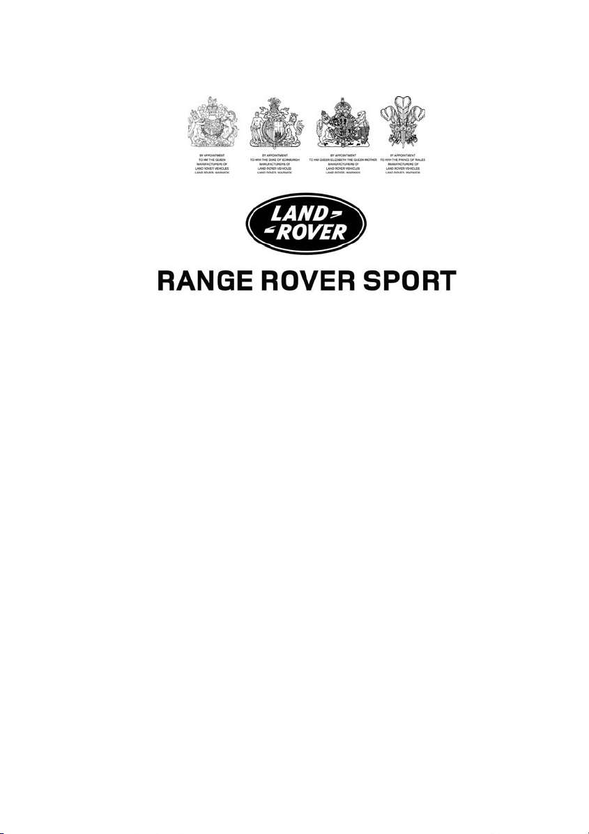
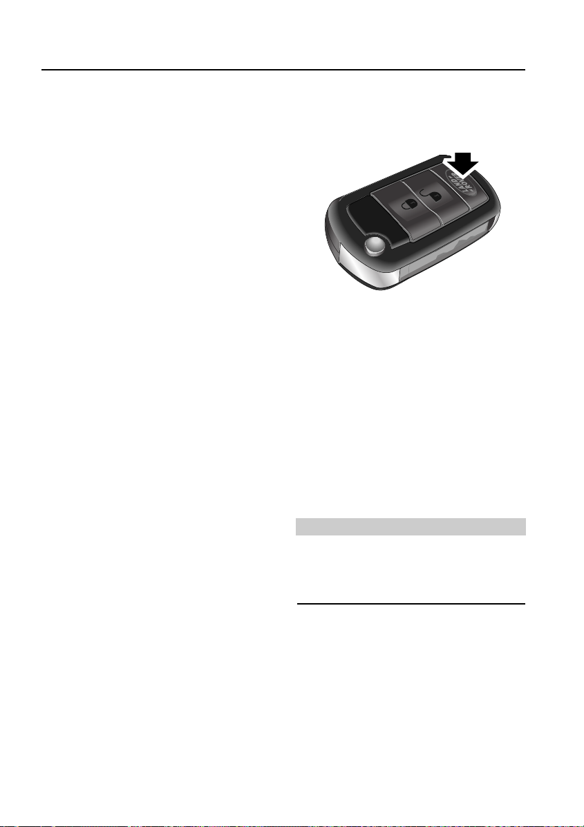
THE REMOTE HANDSET
1
2
3
4
Partial arming
If the driver’s door is not fully closed when the
handset lock button is pressed the vehicle horn
will activate. Until the door is fully closed the
vehicle will remain unlocked and unprotected
by the alarm system.
EMERGENCY UNLOCKING
H5910G
1. Key release button. Press to release the
folded key.
2. Lock button. Superlocks all doors and
activates perimetric alarm. If interior space
protection and tilt sensor options are fitted,
they can be over-ridden by pressing the
button twice within 3 seconds. See
Superlocking, 30, Perimetric alarm, 31,
Interior space protection*, 31, and Tilt
Sensor*, 31.
Note: When the doors have been
superlocked, they cannot be opened from
inside the vehicle.
3. Unlock button. Press once to disarm all
alarm features and unlock driver’s door
only. Press twice to open all doors.
4. Land Rover button. The handset can be
programmed to initiate one of 5 features;
Panic alarm, Headlamp courtesy delay
Tailgate release, Tailglass release or Air
suspension control. For a full description of
how to programme this button see ‘LAND
ROVER’ BUTTON, 26.
H5946G
If the handset should fail there is an emergency
access feature on the left-hand front door lock.
With the key inserted into the slot beneath the
handle cap, the cap can be pulled outwards
slightly and then moved backwards to unhook
it. The key can now be used to unlock the
vehicle. For a full description of this feature see
Emergency locking/unlocking, 35.
7
Page 8
WWW.MANUALS.WS
WWW.MANUALS.WS
Quick Overview
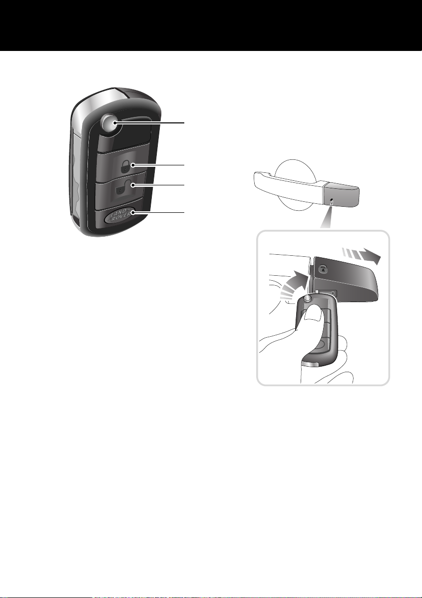
FACIA CONTROLS
1 2
43 5
A
U
T
O
123
10
9 8
ABC DEF
456
JKL MNOGHI
789
TUV WXYZPQRS
0
7
CD 3 14 : 54
2Tr 15:43
123456
6CD-465
6
H5911L
1. Headlamps and direction indicator controls
2. Wiper and washer control
3. Audio/display controls
4. Hazard warning light switch
5. Heater/air conditioning controls
6. Display screen
7. Electric parkbrake switch
8. Starter switch
9. Cruise Control switches
10. Lamps master switch
Note: The precise specification and location of
the controls may vary according to territorial
requirements and from vehicle to vehicle.
*
*
For a full description of facia controls and their
functions, see FACIA CONTROLS, 77.
8
Page 9
WWW.MANUALS.WS
WWW.MANUALS.WS
Quick Overview
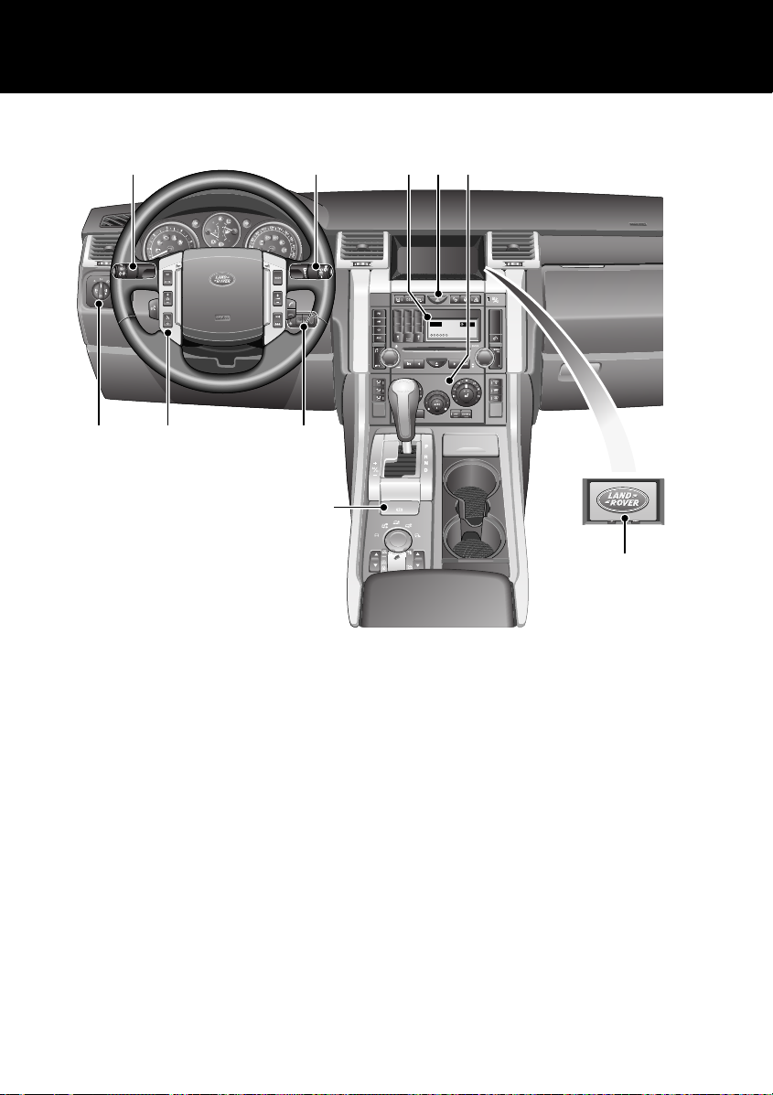
WARNING LIGHTS
2 3 4 5
1
H5931L
1. Dynamic Response (RED).
2. Battery charging (RED).
3. Low oil pressure (RED).
4. Safety belts (RED).
5. Airbag SRS (RED).
6. Brakes (RED).
7. Parkbrake (RED).
If one of these red warning lights illuminates, a
serious fault is indicated. Stop the vehicle and
refer to the main section of this handbook.
For a full description of warning lights and their
functions, see WARNING INDICATORS, 97
6 7
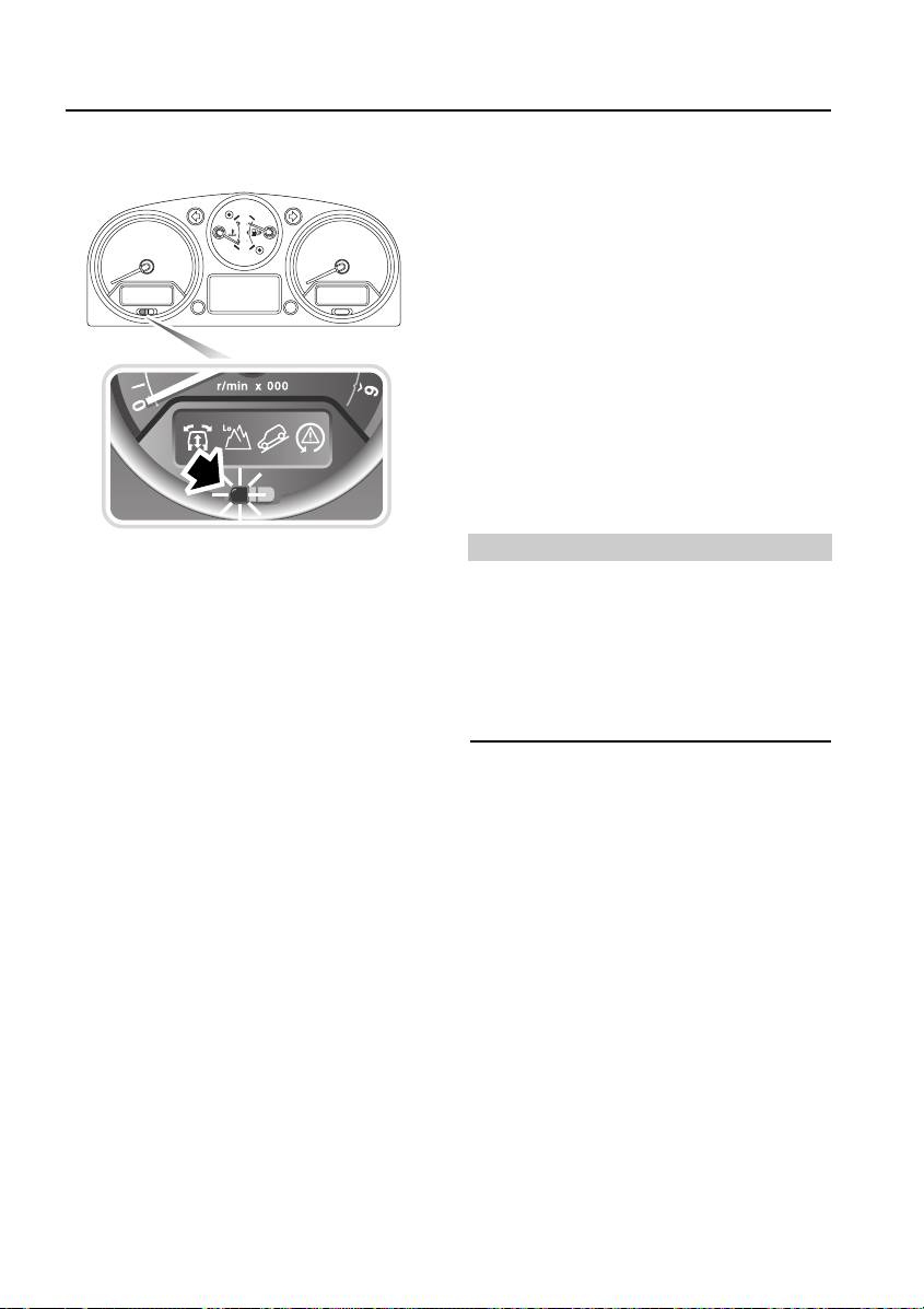
SERVICE INTERVAL INDICATOR
H5949G
To view the next service date, turn the starter
key to position 1 and then, within 5 seconds,
press the System Check control button
(arrowed). The next service date is displayed
(dd.mm.yy) for 5 seconds.
For a full description of this feature, see
SERVICE INTERVAL INDICATOR, 95.
9
Page 10
WWW.MANUALS.WS
WWW.MANUALS.WS
Quick Overview
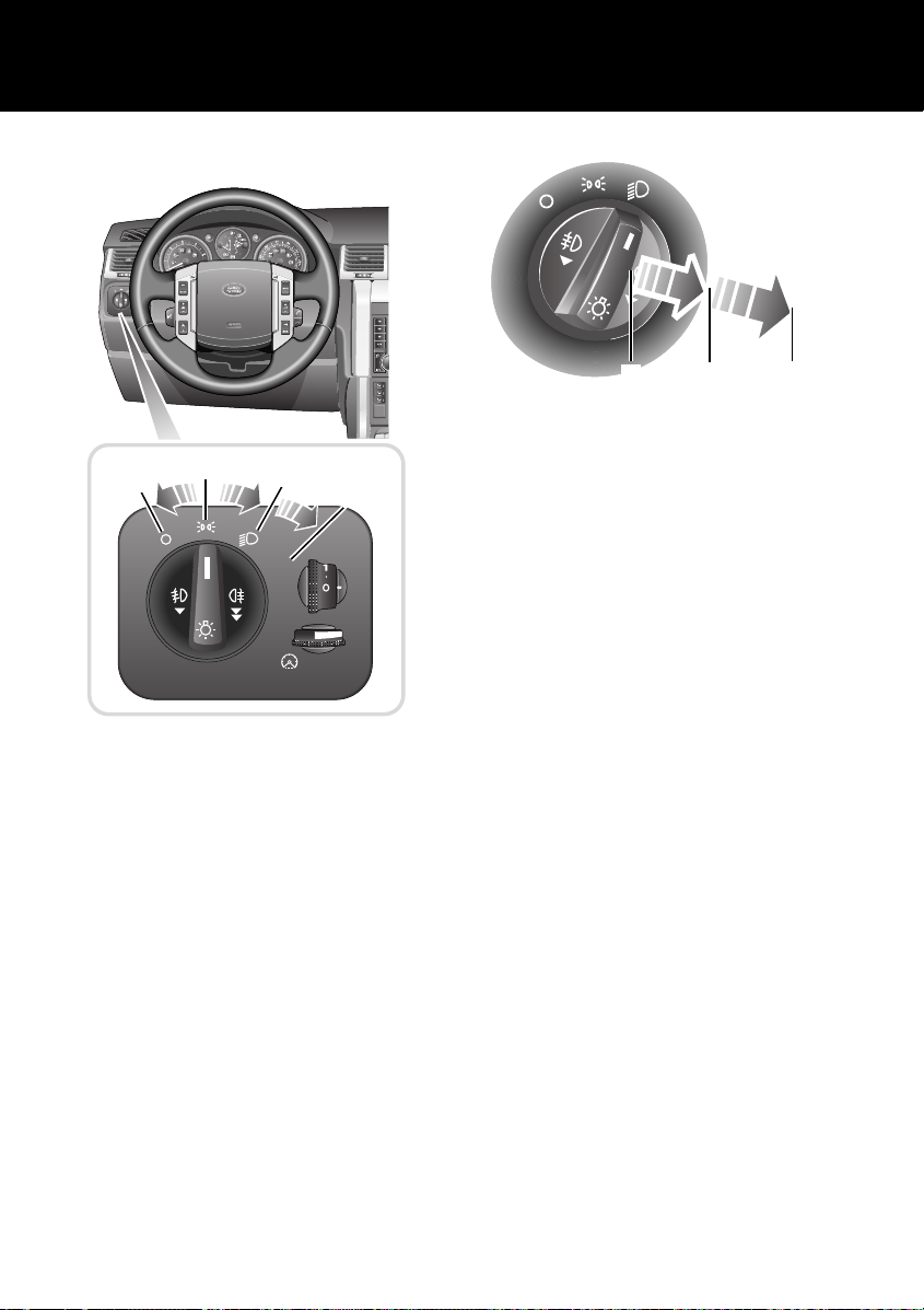
LAMPS MASTER SWITCH
AUTO
AUTO
1
H5934L
1. Off.
2. Position lamps.
3. Low beam headlamps.
4. Auto lamps
For a full description of these functions, see
EXTERIOR LAMPS, 104.
2
*
3
4
AUTO
H5936G
The detent positions from fully pushed in are:
1. Off
2. Front fog lamps
3. Rear fog lamps
If front fog lamps are not fitted, the rear fog
lamps come on at the first pull of the switch.
Headlamp delay feature
When you leave the vehicle in a darkened
situation you can set the headlamps to remain
on for a while.
With the master switch in positions 2, 3 or 4,
turn the starter switch off and remove the key.
Turn the master switch to the off position. The
headlamps will remain on for up to 240
seconds. For a full description of this feature
and how to set the time delay, see Headlamp
courtesy delay, 106.
1
*
2
3
10
Page 11
WWW.MANUALS.WS
WWW.MANUALS.WS
Quick Overview
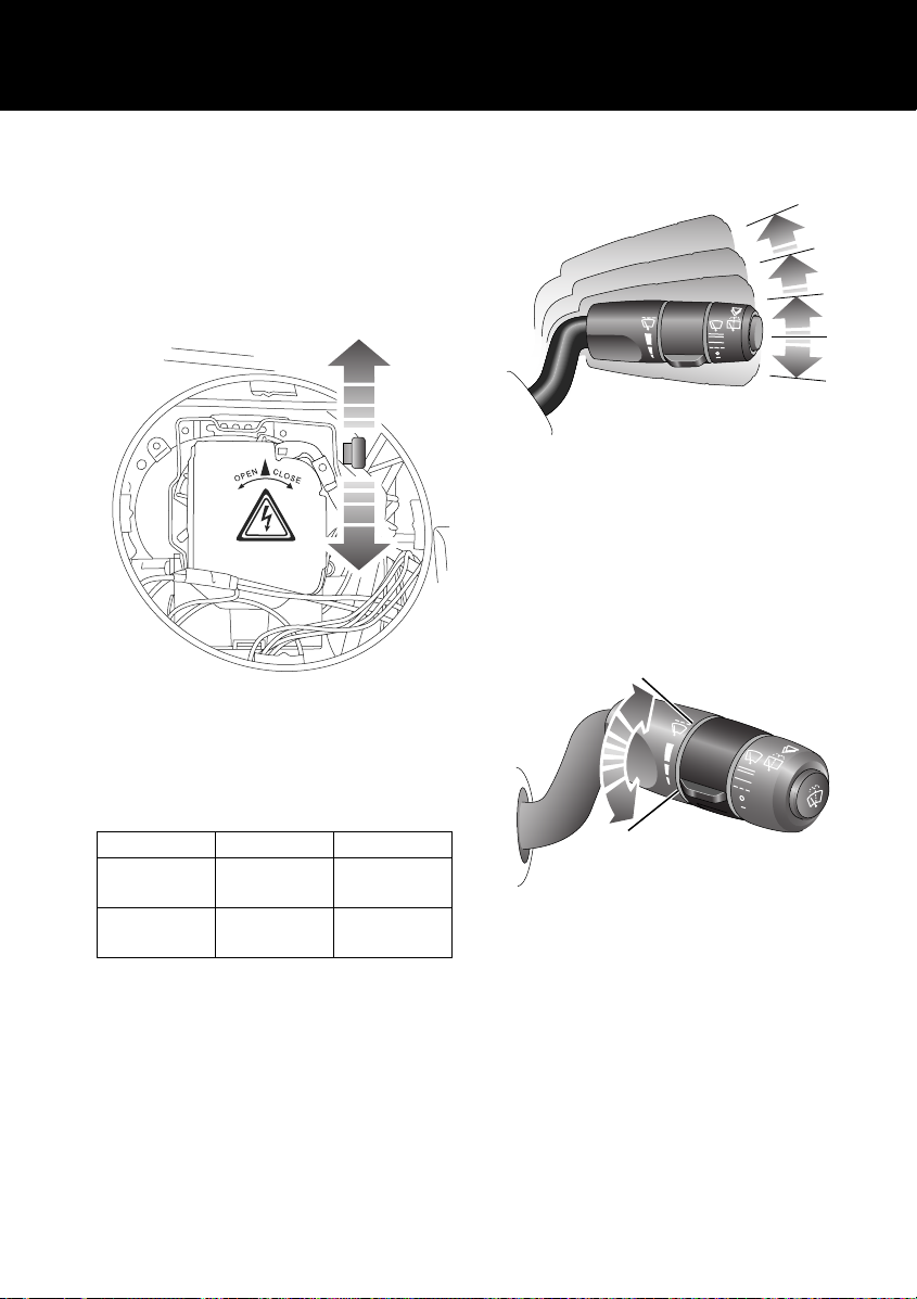
Headlamp beam adjustment
Position of the lever will vary depending on type
of headlamps and side of vehicle.
When this is moved it enables the vehicle to be
driven in opposite-hand-drive markets without
having to stick blanking decals onto the
headlamp lens.
WIPERS & WASHERS
3
2
1
H5937G
1. Intermittent wipe
2. Normal speed wipe.
3. Fast speed wipe.
For a single wipe, pull the lever down and
release immediately.
Intermittent variable delay
H6339G
Follow the process shown in HEADLAMP UNIT,
296 to gain access to the inside of the headlamp
unit. Move the lever to adjust the beam.
Lever default position
Halogen Bi-Xenon
Right hand
side lamp
Left hand
side lamp
Down Up
Up Up
H5938G
With the lever in position 1, rotate the switch to
vary the delay between wipes.
11
Page 12
WWW.MANUALS.WS
WWW.MANUALS.WS
Quick Overview
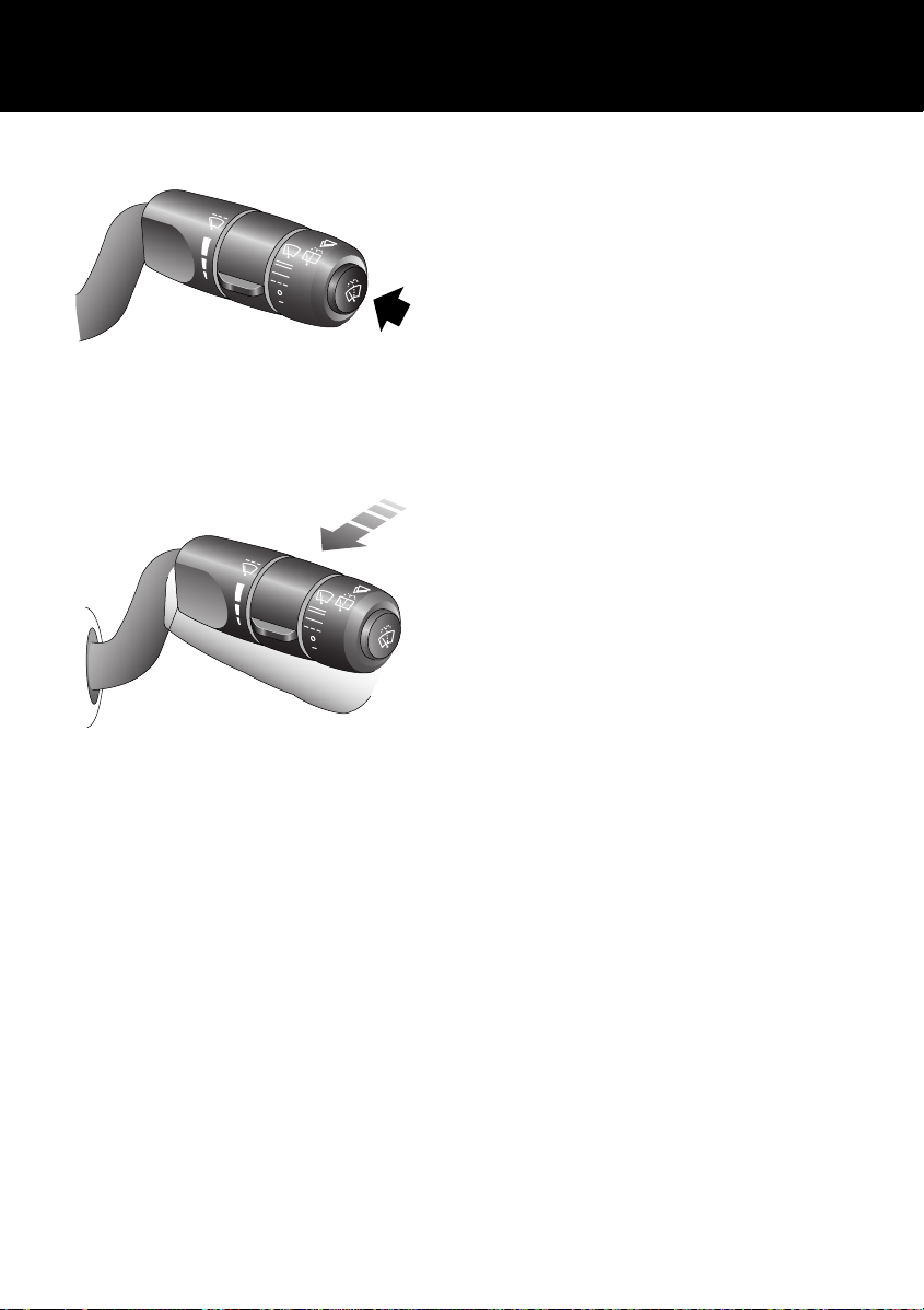
Windscreen washer control
H5939G
Rear window wash/wipe
H5940G
For more detailed information on the wash/wipe
system, see WINDSCREEN WIPERS, 109
12
Page 13

WWW.MANUALS.WS
WWW.MANUALS.WS
Quick Overview
CONFIGURABLE FEATURES
Settings options (trip computer)
A number of features can be configured via the settings menu that can be displayed on the main
message centre. See SELECTING SETTINGS OPTION, 81.
SETTINGS CHOICE
TRIP DISTANCE UNITS (odometer) MILES/KM
FUEL USAGE UNITS MPG
l/100km
Km/l
o
EXTERNAL TEMPERATURE
OVERSPEED WARNING Off
HEADLAMP OFF DELAY 30/60/120/240 seconds
AUTO DOOR LOCK (speed related locking) ON/OFF
REVERSE MIRROR DIP ON/OFF
LAZY ENTRY ON/OFF
RESTORE DEFAULT SETTINGS YES/NO
Remote handset
• Single point entry, allowing only the drivers
door to be opened remotely. See,
Single-point entry, 32.
• Panic alarm, for personal protection. See,
‘LAND ROVER’ BUTTON, 26.
• Headlamp courtesy delay, providing
lighting for personal safety. See,‘LAND
ROVER’ BUTTON, 26.
• Tailgate release function, releases the
tailgate as a whole. See,‘LAND ROVER’
BUTTON, 26.
• Tailglass release function, releases only the
tailglass. See,‘LAND ROVER’ BUTTON, 26.
• Air suspension control, allows remote
operation of the air suspension. See,‘LAND
ROVER’ BUTTON, 26.
C or oF
20 - 250 km/h or 15 to 140 mph in 5-unit steps
(Units set as trip distance)
Starter key reminder
Provides an audible warning indicating that the
key is in the starter switch when the drivers
door is open. See, Starter key reminder, 102.
Passenger airbag disabling
The safest place for a child seat is fitted to the
rear seating. However, if it is necessary to fit a
child seat to the front passenger seat the front
passenger airbag must be disabled. See,
PASSENGER AIRBAG DISABLING SWITCH, 66.
Daytime running lamps
Unless prevented by legislation, it is possible to
automatically switch on the exterior lamps
whenever the engine is running. See, Daytime
running lamps*, 107.
13
Page 14
WWW.MANUALS.WS
WWW.MANUALS.WS
Quick Overview
Speed dependant wiper mode
The wiper speed in all modes can be
automatically varied according to vehicle
speed. See, Speed-dependant mode*, 110.
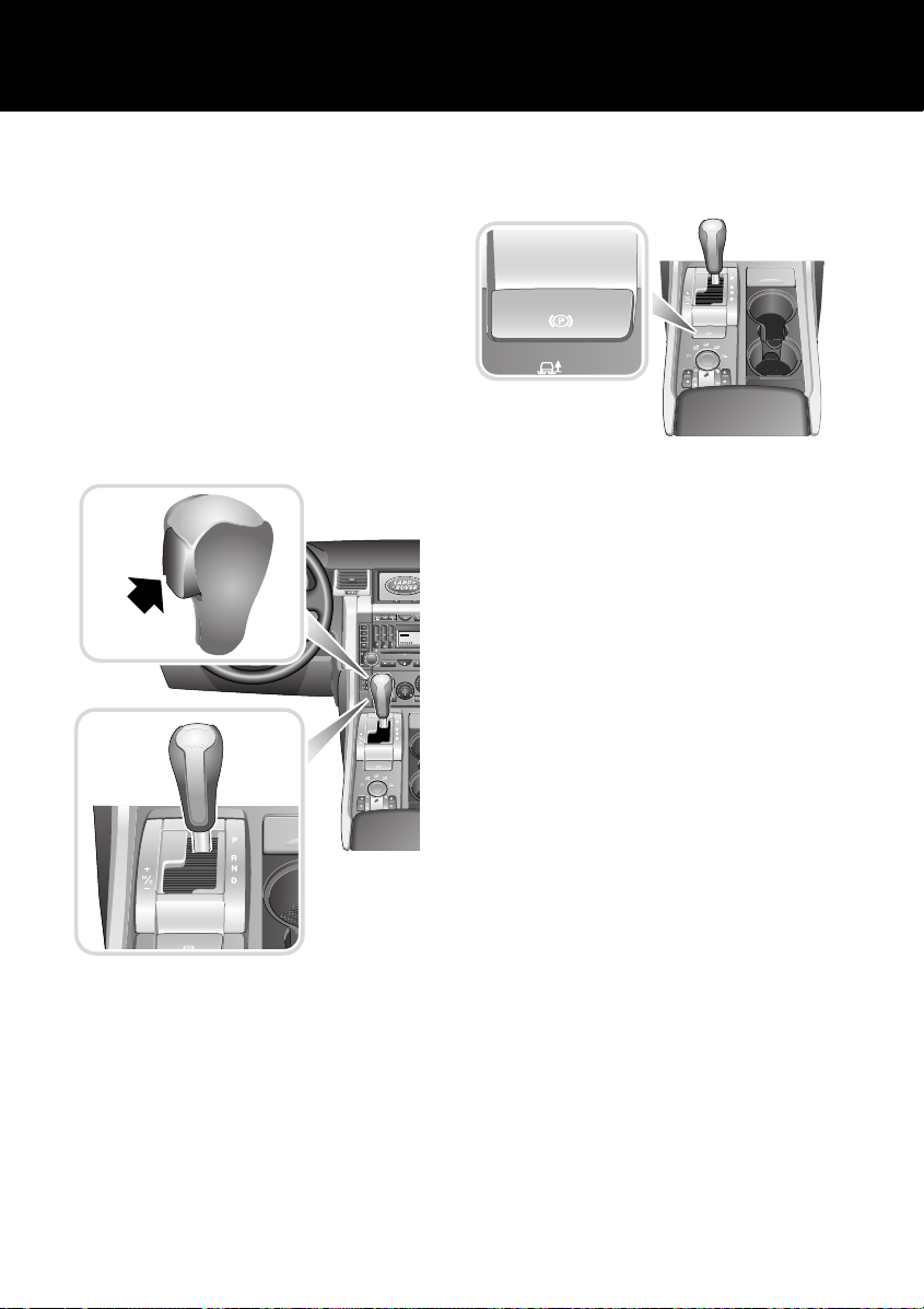
PARKBRAKE
The parkbrake is electrically operated.
AUTOMATIC TRANSMISSION
INTERLOCKS
Vehicles can only be started when the gear
selector lever is in the ‘P’(Park) or ‘N’(Neutral)
position.
To move the lever from ‘P’ to ‘R’, ‘R’ to ‘P’ or ‘N’
to ‘R’, the selector release button (see inset)
must be pressed.
A
U
T
O
123
456
789
ABC DEF
JKL MNOGHI
CD 3
TUV WXYZPQRS
123456
0
H5951L
To apply the parkbrake, lift the lever and release
it. A RED indicator light in the instrument pack
will illuminate continuously.
To release the parkbrake the starter key must be
switched on and pressure must be applied to
the foot brake.
The parkbrake will release automatically if the
2Tr 15:43
accelerator pedal is pressed. To delay this
release, hold the parkbrake lever in the raised
position until you are ready to move, then
release it.
For more detailed information on the parkbrake,
see PARKBRAKE, 184.
H6171L
To move from ‘P’ or ‘N’ into a drive gear
position, the foot brake must be applied.
For more detailed information on the automatic
gearbox, see AUTOMATIC TRANSMISSION
USE, 164.
14
Page 15
WWW.MANUALS.WS
WWW.MANUALS.WS
Quick Overview
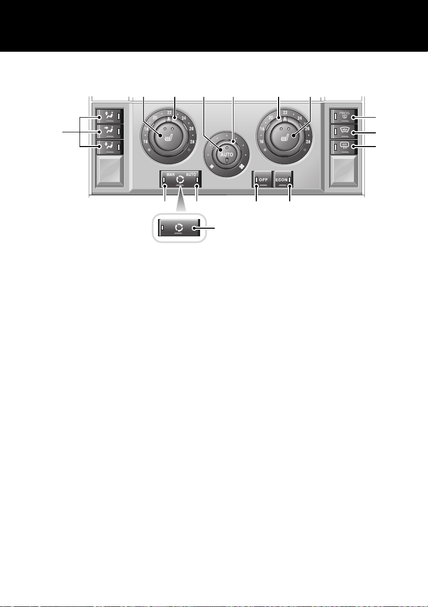
TEMPERATURE CONTROLS
12 1 12
4
H6099G
1. Auto mode:
Press for fully automatic operation.
2. Blower control
3. Temperature controls:
Rotate anticlockwise for maximum cooling.
4. Air distribution controls
5. Air recirculation control - manual
6. Air recirculation control - auto
7. Off
8. Economy mode
9. Heated rear screen
10. Heated front screen.
11. Defrost mode
Press to defrost or demist the windscreen.
12. Front seat heaters
For more detailed information on the climate
control system, see TEMPERATURE
CONTROLS, 119.
*
*
3 2 3
5 6 7 8
*
11
10
9
5
15
Page 16
WWW.MANUALS.WS
WWW.MANUALS.WS
Quick Overview
AUTOMATIC MIRROR DIPPING
If your vehicle is fitted with the driver’s seat
memory option, the door mirrors may dip when
reverse gear is selected. This gives the driver a
view of the kerbside to aid vehicle positioning
when reversing.
The feature is optional and can be adjusted by
the user.
For more detailed information on automatic
mirror dipping, see Automatic mirror
dipping*, 76.
RESONANCE WITH LOWERED
WINDOWS
If a resonance/booming sound occurs with only
the rear windows open, lowering a front
window about 25 mm (1 inch) will eliminate the
condition. This will change the frequency of the
air volume moving in/out of the vehicle and
thus lessen or remove the booming sound.
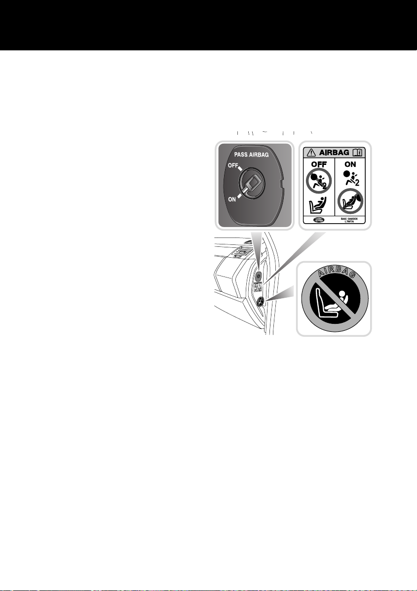
AIRBAG DISABLING
The airbag directly ahead of the front passenger
seat can be disabled. Although the
recommended and safest position for a child
seat is in the rear seats, the front passenger
seat is an optional position.
H6033L
From the passenger side of the car, open the
front door and insert the starter key into the
airbag disabling switch. Turn to the ‘OFF’
position.
For more detailed information on airbag
disabling, see PASSENGER AIRBAG
DISABLING SWITCH, 66.
16
Page 17
WWW.MANUALS.WS
WWW.MANUALS.WS
Quick Overview
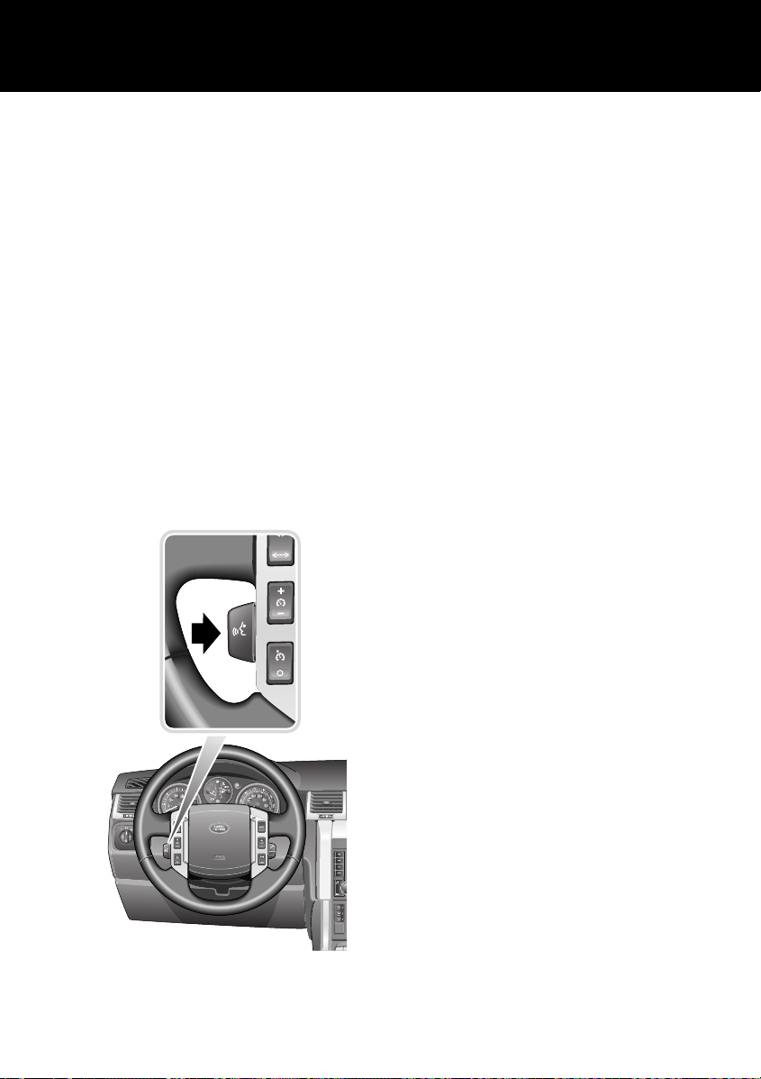
VOICE RECOGNITION*
Voice control provides a safe and convenient
way of operating the audio system without the
need to operate the controls manually. This
enables you to concentrate fully on driving the
vehicle, and removes the need to divert your
attention from the road ahead in order to
change settings, or receive feedback from the
system.
A number of voice commands are available, and
with a little experience you will find them easy
and convenient to use. Whenever you issue one
of the defined commands with the system
active, the voice control system converts your
command into a control signal for the audio
system. Your inputs take the form of dialogues
or commands. You are guided through these
dialogues by announcements or questions.
Activating the system
To activate voice control:
• Briefly pull the control paddle (your Audio
will mute at this point). A brief acoustic
signal will be heard, and ‘LISTENING’ will
be displayed on the main message centre
to indicate that the system is now waiting
for a voice command.
Note: It is only necessary to use the steering
wheel voice control paddle at the beginning of
each voice session.
Defined voice commands
The voice control system understands
predefined commands which need to be quoted
word for word.
An audio feedback of voice commands is
available. To activate the feedback, pull the
voice control paddle briefly and give one of the
following commands:
General commands
• Voice help: To list all commands.
• Notepad Help: To list Notepad commands.
Audio commands
• Radio help: To list Radio commands.
• CD help: To list CD commands.
Please refer to the Audio System Handbook
for full operating instructions.
Navigation & Telephone commands
• Phone help: To list telephone commands.
• Navigation help: To list Navigation
commands.
AUTO
H6159L
Please refer to the Navigation, TV &
Telephone Handbook for full operating
instructions.
For further information see VOICE
RECOGNITION*, 148.
17
Page 18
WWW.MANUALS.WS
WWW.MANUALS.WS
Filling Station Information
Filling Station Information
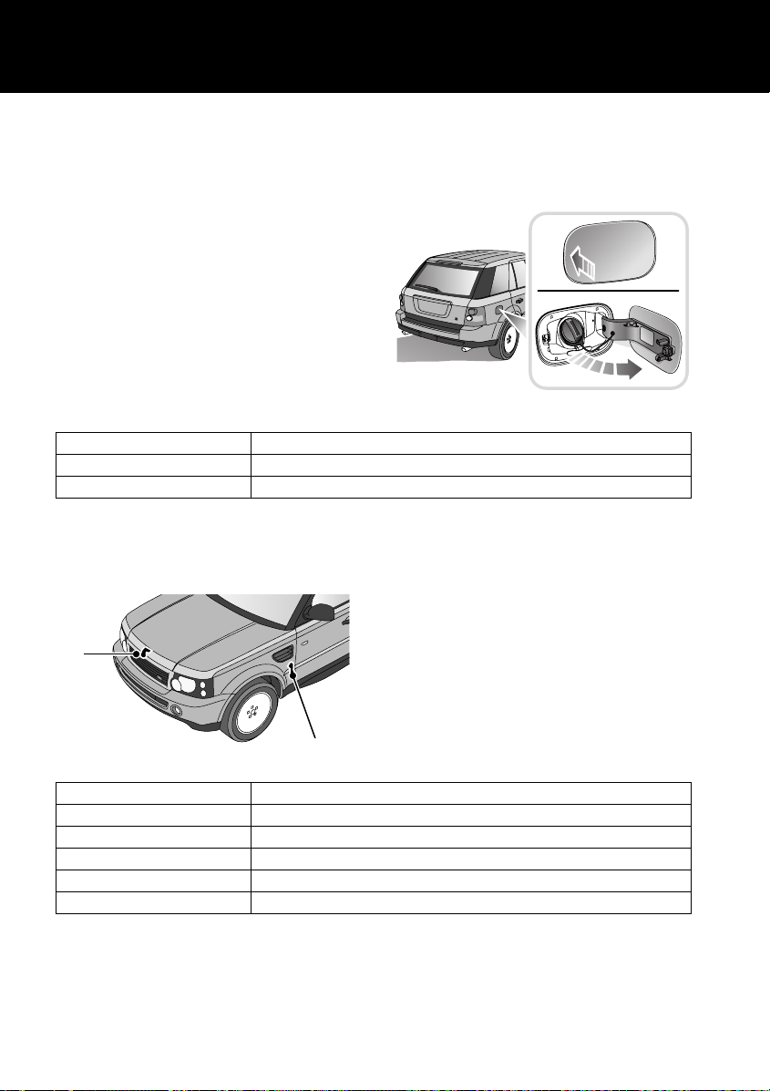
FUEL FILLER
The fuel filler is located in the rear right-hand
wing. Ensuring that the vehicle is not
superlocked, press the fuel filler flap to open.
The fuel filler flap springs out, revealing the
filler cap.
Unscrew the filler cap and place it on the
projection on top of the hinge of the fuel filler
flap.
Insert the pump nozzle into the filler neck,
pushing aside the spring-loaded cover.
When delivery is complete, withdraw the nozzle
and replace the cap. Tighten the cap clockwise
until you hear it click three times. Return the
fuel filler flap to its closed position.
H5944G
Fuel type
Petrol vehicles Premium unleaded 95 RON
Diesel vehicles To EN590 specification. NOT compatible with Bio-diesel fuels.
Note: For more detailed information, see LUBRICANTS AND FLUIDS, 307.
OPENING THE BONNET
1
H5945G
Engine oil top-up
V8 petrol vehicles Use a 5W/30 oil to specification ACEA:A1or A3 (with API SJ or SL)
Engine oil top-up
Diesel vehicles Use a 5W/30 oil to specification ACEA: B1/B3
Cooling system top-up
All vehicles to -36°C (-33°F) 50% mix of water and an approved antifreeze
Note: For more detailed information, see LUBRICANTS AND FLUIDS, 307
2
1. Inside bonnet release
2. Bonnet safety catch
18
Page 19

WWW.MANUALS.WS
WWW.MANUALS.WS
Filling Station Information
TYRE PRESSURES
Air pressure naturally increases in warm tyres
(after the vehicle has been driven for a while). If
you have to check warm tyres, you should
expect the pressures to have increased by
between 30 and 40 kPa (0.3 to 0.4 bar) (4 to 6
2
). In this circumstance, NEVER let air out
lbf/in
of the tyres in order to match the recommended
pressures.
Loading condition kPa bar lbf/in
Normal operating conditions Front 230 2.3 34
Vehicle loaded to maximum gross vehicle weight Front 260 2.6 38
Temporary spare wheel (All operating conditions) 420 4.2 60
2
Rear 250 2.5 36
Rear 290 2.9 42
19
Page 20

WWW.MANUALS.WS
WWW.MANUALS.WS
20
Page 21
WWW.MANUALS.WS
WWW.MANUALS.WS
General Information
General Information
HANDLING CHARACTERISTICS
WARNING
Your vehicle has a higher ground clearance
and, hence, a higher centre of gravity than
ordinary passenger cars. This will result in
different handling characteristics.
Inexperienced drivers should take additional
care, particularly in off-road driving
situations and when performing abrupt
manoeuvres on unstable surfaces.
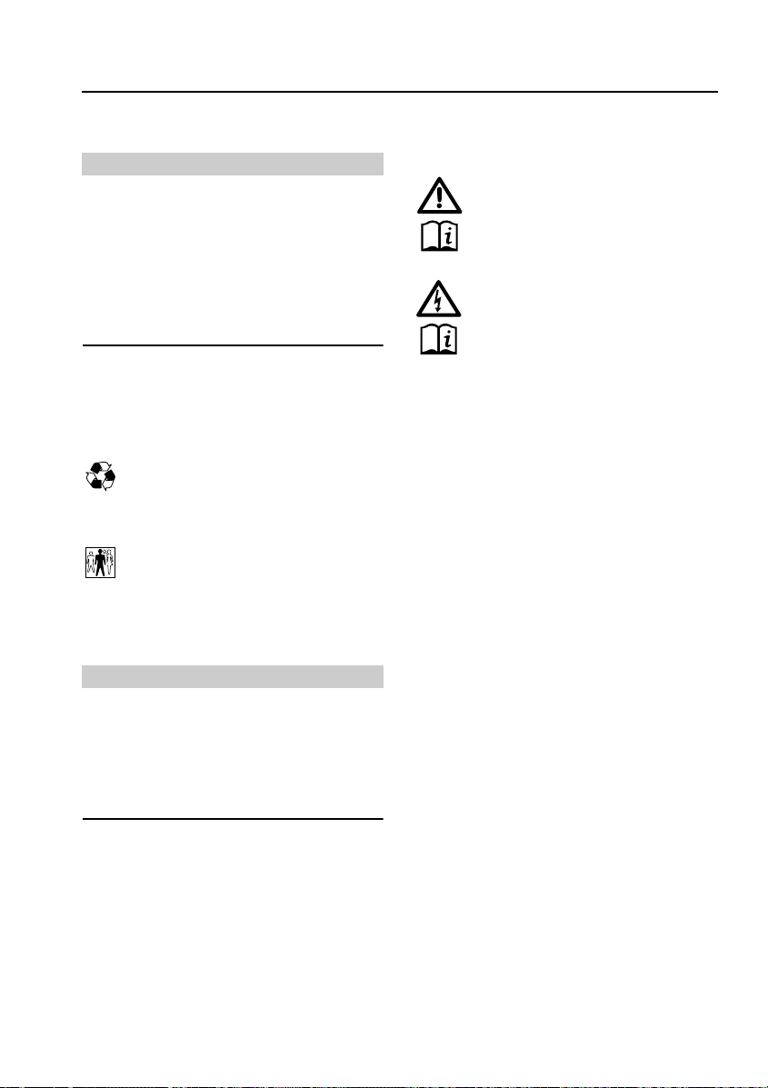
SYMBOLS
The following symbols used within the
handbook call your attention to specific types of
information.
This recycling symbol identifies those
items that must be disposed of safely in
order to prevent unnecessary damage
to the environment.
This symbol identifies those features
that can be adjusted or disabled/enabled
by a Land Rover Dealer/Authorised
Repairer.
WARNINGS IN THIS HANDBOOK
WARNING
Safety warnings are included in this
handbook. These indicate either a procedure
which must be followed precisely, or
information that should be considered with
great care in order to avoid the possibility of
personal injury.
WARNING LABELS ATTACHED
TO THE VEHICLE
Warning labels attached to your
vehicle bearing this symbol mean: DO
SECURITY CARD
The security card, supplied with the literature
pack, contains important emergency
information. It is ESSENTIAL that you keep the
card safe from theft and ensure that it is passed
to the new owner if you sell the vehicle.
• Locking wheel nut number: If your vehicle
• VIN (Vehicle Identification Number): This
Caution: Never leave the security card inside
the vehicle when it is unattended.
NOT touch or adjust components until
you have read the relevant
instructions in the handbook.
Labels showing this symbol indicate
that the ignition system utilises very
high voltages. DO NOT touch any
ignition components while the starter
switch is turned on!
has locking wheel nuts, you will have been
provided with a special wheel nut socket to
remove them. You will need to quote this
number to obtain a replacement socket.
identity number is unique to your vehicle
and is essential proof of its specification.
The number can also be found in various
locations around the vehicle (see VEHICLE
IDENTIFICATION NUMBER (VIN), 270).
Caution: Cautions are included in this
handbook. These indicate either a procedure
which must be followed precisely, or
information that should be considered with
great care in order to avoid the possibility of
damage to your vehicle.
21
Page 22
WWW.MANUALS.WS
WWW.MANUALS.WS
General Information
SERVICE PORTFOLIO
The Service Portfolio book included in your
literature pack contains important vehicle
identification information as well as useful
consumer advice.
Most important of all, however, is the section
on maintenance. This outlines the servicing
requirements for your vehicle and also includes
the service record slips, which the Dealer
should sign and stamp to certify that the routine
services have been carried out at the
recommended intervals.
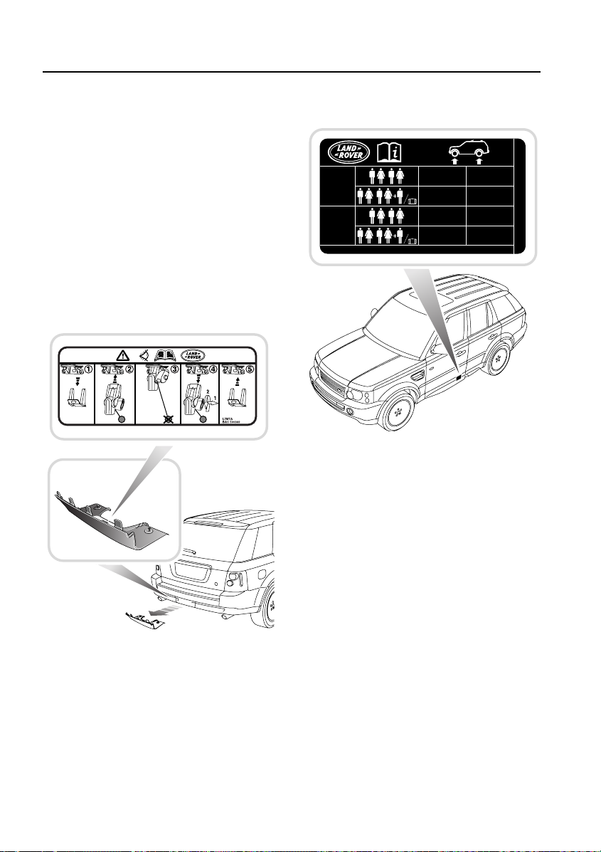
TYRE PRESSURE LABEL
235/65R17
255/55R18
255/50R19
275/40R20
T175/80R19
MAX.
MAX.
230
(kpa)
260
(kpa)
420
(kpa)
420
(kpa)
(BAR)33(PSI)
(BAR)
(BAR)60(PSI)
(BAR)60(PSI)
2.3
2.6
4.2
4.2
(kpa)
38(PSI) 290
(kpa)
(kpa)
(kpa)
250
420
420
2.5
(BAR)36(PSI)
2.9
(BAR)42(PSI)
4.2
(BAR)60(PSI)
4.2
(BAR)60(PSI)
RANGE ROVER L7MTA
RTC500340
TOW BAR LABEL
H5955L
Information on tyre pressures for differing tyres
and vehicle loadings is given on a label attached
to the ‘B’ post on the driver’s side.
For further information on tyre pressures see
Tyre pressures, 260; TYRE PRESSURE
MONITORING SYSTEM*, 264; WHEELS &
TYRES, 313.
H5954G
A label, located on the inside face of the rear
bumper access hatch, shows the attachment
and removal procedure for the tow bar system.
For information on removing and fitting the
detachable tow bar, see Towing, 207.
22
Page 23
WWW.MANUALS.WS
WWW.MANUALS.WS
General Information
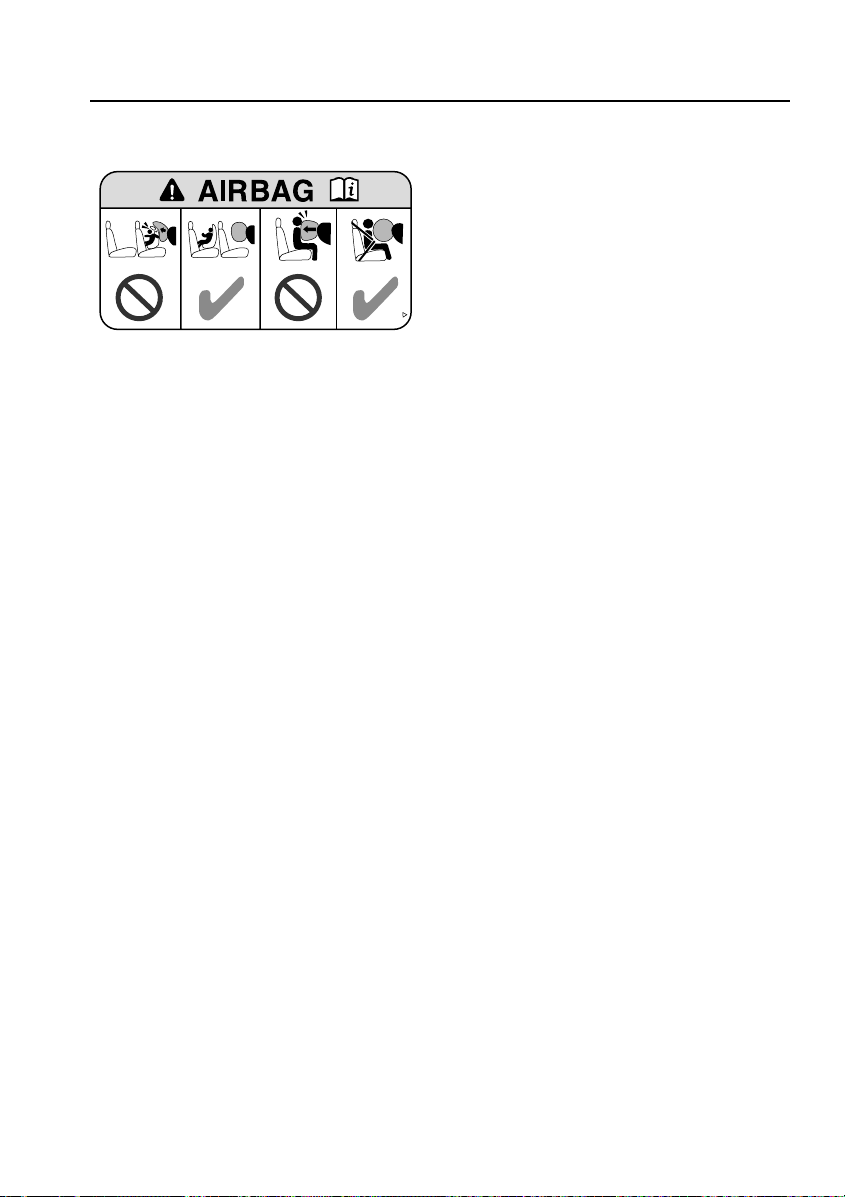
SUN VISOR LABELS
H5953G
Always take careful note of warning information
about the airbag SRS affixed to the driver’s and
passenger’s sun visor.
An additional label, located on the ‘B’ post,
warns against the use of rear-facing child seats
in the front passenger seat.
For further information concerning the airbag
SRS and the use of child restraints, consult the
relevant sections of this handbook.
BRAKE PADS
Brake pads require a period of bedding in. For
the first 800 km (500 miles), you should avoid
situations where heavy braking is required.
Regular servicing is vital to ensure that the
brake pads are examined for wear and changed
periodically to ensure long term safety and
optimum performance.
IN AN EMERGENCY
Remember the breakdown safety code
If a breakdown occurs while travelling:
• Wherever possible, consistent with road
2U5A-5400014-DA
safety and traffic conditions, the vehicle
should be moved off the main
thoroughfare, preferably into a lay-by. If a
breakdown occurs on a motorway, pull well
over to the inside of the hard shoulder.
• Switch on hazard lights.
• If possible, position a warning triangle or a
flashing amber light at an appropriate
distance from the vehicle to warn other
traffic of the breakdown, (note the legal
requirements of some countries).
• Consider evacuating passengers through
nearside doors onto the verge as a
precaution in case your vehicle is
accidentally struck by other traffic.
23
Page 24

WWW.MANUALS.WS
WWW.MANUALS.WS
General Information
ON-BOARD EVENT DATA
Service data recording
Service data recorders in your vehicle are
capable of collecting and storing diagnostic
information about your vehicle. This potentially
includes information about the performance or
status of various systems and modules in the
vehicle such as engine, throttle, steering or
brakes.
In order to properly diagnose and service your
vehicle, Land Rover and service and repair
facilities may access vehicle diagnostic
information through a direct connection to your
vehicle.
Event data recording
Other modules in your vehicle - event data
recorders - are capable of collecting and storing
data during a crash or near-crash event. The
recorded information may assist in the
investigation of such an event. The modules
may record information about both the vehicle
and the occupants, potentially including
information such as:
• How various systems in your vehicle were
operating.
• Whether or not the driver and passenger
seat belts were buckled.
• How far, if at all, the driver was depressing
the accelerator and/or the brake pedal.
• How fast the vehicle was travelling.
• Where the driver was positioning the
steering wheel.
To access this information special equipment
must be connected directly to the recording
modules. Land Rover do not access event data
recorder information without obtaining
consent, unless pursuant to court order or
where required by law enforcement, other
government authorities or third parties acting
with lawful authority.
Other parties may seek to access the
information independently of Land Rover.
24
Page 25
WWW.MANUALS.WS
WWW.MANUALS.WS
Keys and Handsets
Controls and Instruments
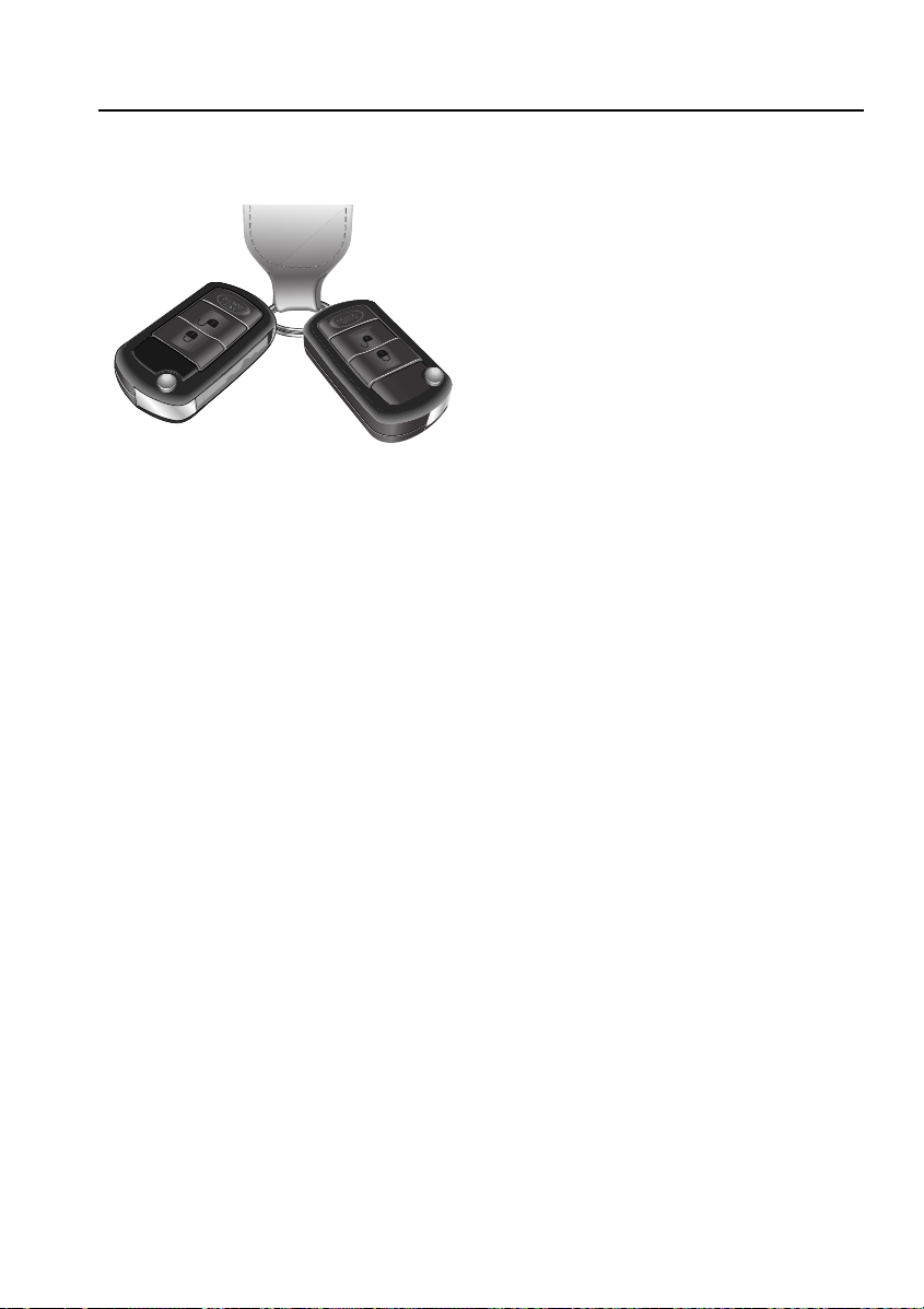
KEYS AND HANDSETS
H5966G
You have been supplied with two remote
handsets with integral keys which operate all of
the vehicle’s locks.
The operation of all transmitter buttons, on all
handsets, will be inhibited whilst a key is in the
starter switch.
Note: The key transmitter may not operate
correctly in areas that are subject to
interference from other radio equipment
operating on a similar frequency. Areas where,
for example, equipment such as amateur radio,
medical devices, telecommunications
equipment or other remotely operated alarms
are in use may cause difficulty. If such
difficulties are experienced, try to operate the
transmitter as close as possible to the vehicle,
or use the key in the door lock.
The keys supplied with your vehicle are
programmed to your security system - the
engine cannot be started without a key
programmed to your vehicle.
Caution: Keep the spare handset key in a safe
place - NOT IN THE VEHICLE.
The other two keys that you have received are
for locking the main glovebox.
Note: Should a key transmitter be lost or
damaged, a replacement can only be obtained
from your Land Rover Dealer/Authorised
Repairer, where it will be programmed to your
vehicle. The dealer will require proof of
ownership, and keep a log of all enquiries for
replacement key transmitters.
It is advisable to notify your dealer as soon as
possible if a key transmitter is lost or stolen,
and have the remaining transmitters
reprogrammed. This will prevent access to the
vehicle using the lost/stolen transmitter.
Remote handset battery
The battery is rechargeable. The fact that the
battery needs recharging will be apparent from
the following:
• ‘KEY BATTERY LOW’ will be displayed in
the main message centre.
• A gradual deterioration in range and
performance will be noticed.
Caution: The handset contains delicate
electronic circuits and must be protected from
impact and water damage, high temperatures
and humidity, direct sunlight and the effects
of solvents, waxes and abrasive cleaners.
Battery recharge
Insert the key into the starter switch and start
the engine. This will start to recharge the
handset battery.
25
Page 26
WWW.MANUALS.WS
WWW.MANUALS.WS
Locks and Alarms
Locks and Alarms
SECURITY SYSTEM
The security system fitted to your vehicle is
Thatcham category one approved, and meets
European regulation 97 and directive 95/56/EC.
Security Information
For your own safety, and that of the vehicle,
when the vehicle is left unattended:
• Apply the park brake
• Remove all keys and transmitters from the
vehicle prior to locking the doors
• Close all doors, windows, luggage
compartment (including blind), sunroof,
and glove box
• Park the vehicle where it is visible (a well lit
area after dark)
• Keep your vehicles keys safely out of sight
• NEVER leave children or pets unattended in
the vehicle
• NEVER leave luggage or valuables on
display
‘LAND ROVER’ BUTTON
Customer programmable button
*
H5947G
The fourth button - marked with the Land Rover
logo - on the remote handset can be
programmed to give remote operation of one of
the following functions:
• panic alarm
• headlamp courtesy delay
• air suspension control
• tailgate release
• tailglass release
Note: Programming and subsequent use of the
‘Land Rover’ button will not occur if the key is
in the starter switch.
WARNING
Be aware that the previously programmed
feature will be activated when the button is
initially pressed to start the programming
sequence.
26
Page 27
WWW.MANUALS.WS
WWW.MANUALS.WS
Locks and Alarms
Handset Programming
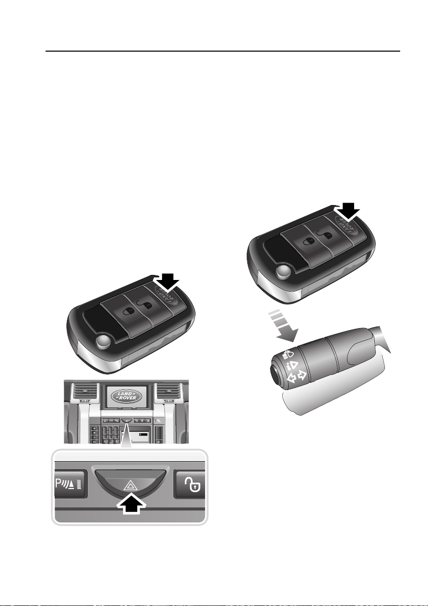
Panic Alarm
This facility is programmed by pressing the
‘Land Rover’ button and, keeping it pressed,
pressing the hazard warning lamps button on
the instrument panel. A chime from the
instrument panel buzzer will confirm successful
programming of the remote’s button.
A short press of the button will now cause the
vehicle’s alarm to be sounded and the hazard
warning lamps to flash.
The alarm is turned off by inserting the key in
the starter, or pressing the lock or unlock
buttons on the remote handset.
Note: In some countries it is an offence to
activate the panic alarm for any purpose other
than an emergency.
Headlamp Courtesy Delay
This facility is programmed by pressing the
‘Land Rover’ button and, keeping it pressed,
flashing the headlamps. A chime from the
instrument panel buzzer will confirm successful
programming of the remote’s button.
A short press of the button will now cause the
vehicle’s headlamps to illuminate for the length
of time specified in Settings. A second press of
the button after three seconds will de-activate
the lamps.
H5974G
123
ABC DEF
456
JKL MNOGHI
789
TUV WXYZPQRS
0
CD 3 14 : 54
2Tr 15:43
123456
6CD-465
H5973G
27
Page 28
WWW.MANUALS.WS
WWW.MANUALS.WS
Locks and Alarms
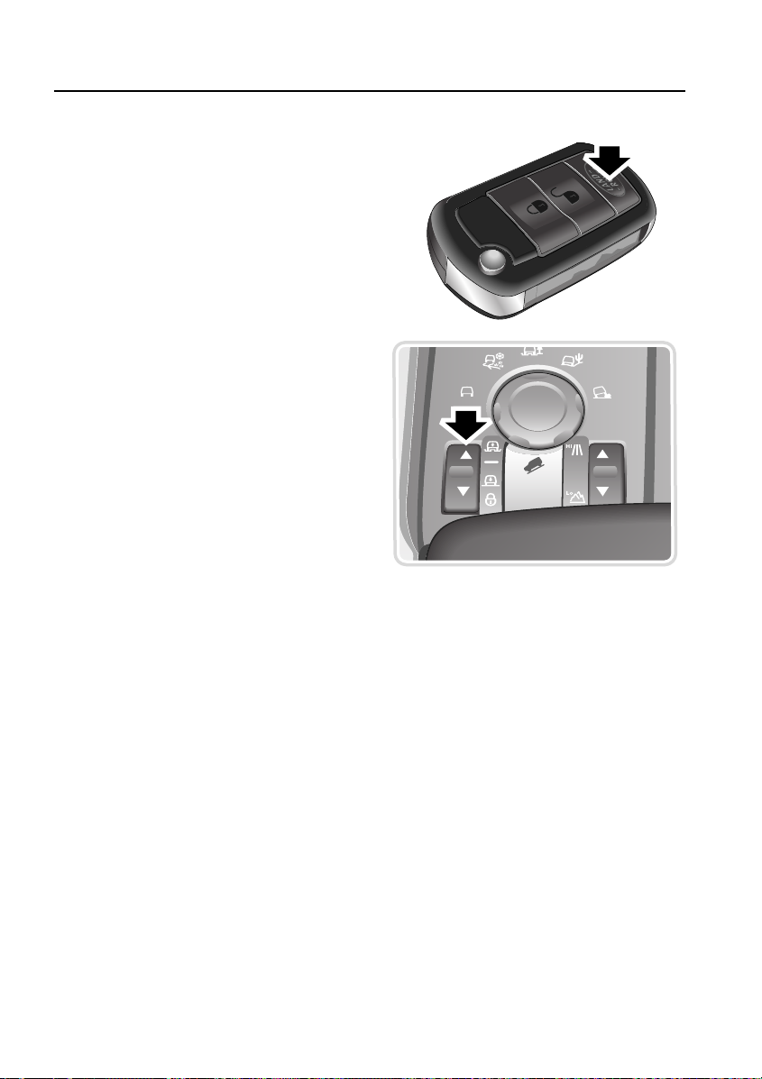
Air Suspension Control
This facility is programmed by pressing the
‘Land Rover’ button and, keeping it pressed,
pressing the suspension control switch. A
chime from the instrument panel buzzer will
now confirm successful programming of the
remote’s button.
Programming of this function must be done
within one minute of switching off the engine.
Pressing and holding the button, then briefly
pressing the lock button on the remote will now
cause the air suspension to rise, provided that
the hazard warning lamps have been switched
on.
Pressing and holding the button, then briefly
pressing the unlock button on the remote will
cause the air suspension to lower, provided that
the hazard warning lamps have been switched
on.
If any button is released during the raising or
lowering of the suspension, all movement of
the suspension will stop. It will restart once the
buttons are pressed again.
For further information see AIR SUSPENSION,
192.
H5975L
28
Page 29
WWW.MANUALS.WS
WWW.MANUALS.WS
Locks and Alarms
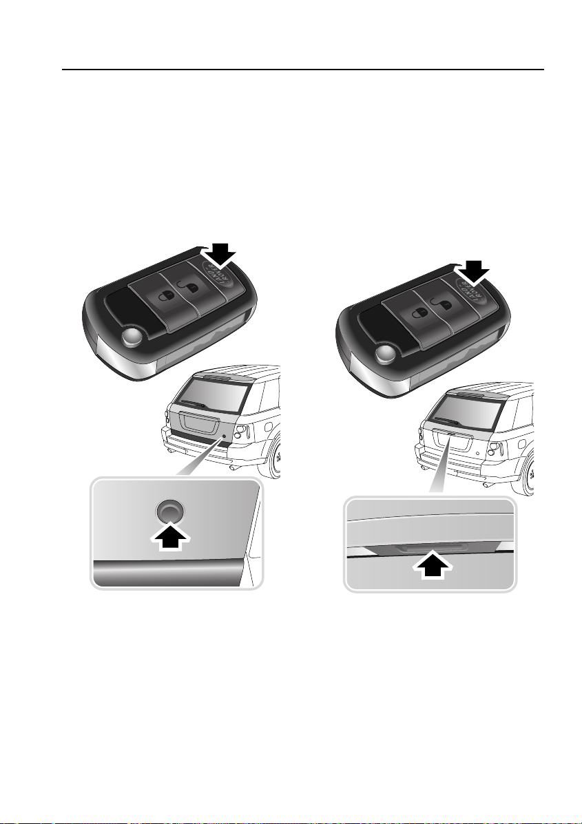
Tailgate Release
This facility is programmed by pressing the
‘Land Rover’ button and, keeping it pressed,
pressing the main tailgate release button on the
rear tailgate. A chime from the instrument panel
buzzer will confirm successful programming of
the remote’s button.
A short press of the button will now cause the
vehicle’s tailgate to release.
Tailglass Release
This facility is programmed by pressing the
‘Land Rover’ button and, keeping it pressed,
pressing the main tailglass release button
situated under the rear number plate plinth. A
chime from the instrument panel buzzer will
confirm successful programming of the
remote’s button.
A short press of the button will now cause the
vehicle’s tailglass to release.
H6369G
H6370G
29
Page 30
WWW.MANUALS.WS
WWW.MANUALS.WS
Locks and Alarms
Anti-theft alarm indicator
1
H5969G
The indicator provides information about the
status of the alarm and immobiliser systems, as
follows:
When the alarm is armed with interior space
protection*:
The indicator will triple flash for 10 seconds
then continue to single flash until the vehicle is
disarmed and immobilised.
When the alarm is armed without interior
space protection:
The indicator will double flash for 10 seconds,
then continue to single flash until the vehicle is
disarmed and immobilised.
When the alarm is disarmed but the vehicle is
immobilised (key out of starter switch):
The indicator will single flash until the alarm is
armed or the vehicle is mobilised.
When the alarm is disarmed and the vehicle
is mobilised (key in starter switch):
The indicator gives a one-second flash on
remobilisation.
If the alarm sounds
If the alarm is triggered, the alarm will sound
and the hazard warning lamps will flash for 30
seconds, before resetting to the same
protection status that existed prior to the alarm
being triggered.
To silence the alarm, press the lock or unlock
button on the remote handset or insert the key
into the starter switch. Pressing the lock button
will keep the alarm armed.
When the vehicle is disarmed, the hazard
warning lamps will quickly flash eight times if
the alarm has sounded since the vehicle was
last armed.
Superlocking
WARNING
For safety, NEVER use Superlocking if
passengers are to remain inside the vehicle in an emergency they would not be able to
escape, or be released by emergency
services. Also, any movement from within the
vehicle would activate the interior space
protection alarm*.
Superlocking is activated by one press of the
lock button on the handset.
When the vehicle is superlocked the doors can
only be opened from inside or outside of the
vehicle with the correct key or key transmitter.
Superlocking immobilises the interior door
handles, thereby preventing an intruder from
gaining entry by smashing a window and
reaching inside the vehicle to operate the door
handles.
30
Page 31

WWW.MANUALS.WS
WWW.MANUALS.WS
Locks and Alarms
Perimetric alarm
This feature is activated automatically
whenever the vehicle is locked using the
handset and protects the doors, bonnet and
tailgate.
If any of these apertures are opened, or a key
that has not been programmed to the vehicle is
inserted into the ignition switch, while the
feature is activated, the alarm will be triggered.
When the perimetric alarm is activated the
direction indicators will flash three times, and
the security system status indicator will flash.
Mislock
If an aperture is open when an attempt is made
to lock the vehicle an audible warning will
sound once to indicate that the vehicle is not
secure.
Interior space protection
Interior space protection is activated whenever
the vehicle is superlocked.
Note: Never activate interior space protection if
windows or sunroof are to be left open, or if
passengers or animals are to be left inside the
vehicle - any movement will activate the alarm.
Interior space protection is designed to protect
the interior of the vehicle from intrusion (entry
by a thief through a smashed window, for
example). Four roof-mounted sensors monitor
the interior space and activate the alarm if air
movement is detected in the passenger
compartment.
Note: Interior space protection cannot be
activated if a door is open.
*
H5972G
Disabling interior space protection:
If there is a requirement to disable interior
space protection (if a window or sunroof is to
be left open, for example), press the lock button
on the remote handset twice within three
seconds.
Tilt Sensor
Your vehicle is fitted with a tilt sensor which
activates the alarm if the vehicle is tilted fore
and aft, or side to side, after it has been
superlocked.
The alarm will sound if theft is attempted by
hoisting onto another vehicle or if a side is lifted
to attempt wheel removal.
Disabling tilt sensor protection:
If you wish to have the doors locked but the tilt
sensor disabled (e.g. when aboard a ferry or
having the vehicle transported on a recovery
truck) press the lock button twice within three
seconds.
*
31
Page 32

WWW.MANUALS.WS
WWW.MANUALS.WS
Locks and Alarms
Single-point entry
This is a personal security feature, which
enables only the driver's door to be unlocked,
leaving the other doors in a locked state.
Single-point entry can be disabled on individual
handset keys by pressing and holding the lock
and unlock buttons together for three seconds.
Repeating the procedure will re-enable the
feature.
Each time single-point entry is turned on or off,
the vehicle will lock then unlock into the
selected mode (all doors unlocked or just
driver’s door unlocked).
Battery-backed sounder
This device will sound the full alarm if the alarm
is activated, or if the vehicle’s battery or the
sounder is disconnected whilst the security
system is armed.
*
ALARM SYSTEM
H5967G
Your vehicle is fitted with a sophisticated
electronic anti-theft alarm and engine
immobilisation system. There are also a
number of additional security features, some of
which are selectable options and some are
standard features of the vehicle.
In order to ensure maximum security and
operating convenience, you are strongly
advised to gain a full understanding of the
features and alternatives available, by
thoroughly reading this section of the
handbook.
Note: FOR MAXIMUM SECURITY ALWAYS
SUPERLOCK THE VEHICLE. If passengers or
animals are to be left in the vehicle, windows
and/or sunroof are left open, or the vehicle is on
a moving platform, e.g. a ferry, lock the vehicle
by pressing the lock button twice within three
seconds. This disables the superlocking, tilt
sensing* and interior space protection*.
32
Page 33

WWW.MANUALS.WS
WWW.MANUALS.WS
Locks and Alarms
LOCKING/UNLOCKING
While it is not necessary to point the handset at
the vehicle, the handset must be within range of
the vehicle when a button is pressed.
Note: If the handset fails to work even when
close to the vehicle, it could be that it is not
synchronised with the system, see Emergency
locking/unlocking, 35. Putting the key in the
starter switch and running the engine for six
minutes will restore full operation.
The operating range may vary depending upon
handset battery condition and may sometimes
be limited by physical and geographical factors
beyond your control.
Note: If a key is in the starter switch, the vehicle
will not respond to remote handset commands.
1
2
3
H5968G
4
Locking with the remote handset
Remove the key from the starter switch and
shut all doors, the bonnet and the tailgate.
The four buttons on the handset are used as
follows:
1. Key release button.
33
Page 34

WWW.MANUALS.WS
WWW.MANUALS.WS
Locks and Alarms
2. Lock button: Press to superlock all doors
and to activate the perimetric alarm and
interior space protection* and activate the
tilt sensor
Sensor*, 31).
Press twice within three seconds to lock all
doors and activate the perimetric alarm,
but NOT activate interior space protection*
or tilt sensor*.
The direction indicator lamps will flash
three times.
3. Unlock button: Press once to disarm the
alarm and unlock the driver’s door and to
activate the ‘Lazy seats’* feature, (see
DRIVER’S SEAT MEMORY FACILITY*,
45). Press again to unlock the remaining
doors (see Single-point entry, 32).
In either case, the interior lamps illuminate
and the direction indicators flash once.
The hazard warning lamps will quickly flash
eight times when the vehicle is disarmed if
the alarm has sounded since the vehicle
was last armed.
4. Customer Configuration - ‘Land Rover’
button: This button can be configured to
operate panic alarm, headlamp courtesy
delay, tailgate release, tailglass release or
suspension control (see ‘LAND ROVER’
BUTTON, 26).
* (see Superlocking, 30, Tilt
Partial arming
If the driver’s door is not fully closed when the
handset lock button is pressed, the doors will
remain unlocked and the alarm will remain
disarmed. A brief sound from the vehicle horn
will confirm that the door is not fully closed.
If a passenger door or other aperture is not fully
closed when the handset lock button is
pressed, the ‘partial arming’ attributes of the
security system will enable as much of the
system to be armed as possible (all fully closed
door, bonnet or tailgate apertures will be
protected, but an open one will not).
A brief sound from the vehicle’s horns will
confirm that an aperture is not fully closed.
As soon as the open aperture is closed, the
system will automatically arm, signalled by
three flashes of the hazard warning lamps, with
interior space protection* activating 30
seconds after all apertures are closed.
Note: The vehicle will not superlock if an
aperture (other than the bonnet) is open.
34
Page 35

WWW.MANUALS.WS
WWW.MANUALS.WS
Locks and Alarms
Emergency locking/unlocking
Removing the cap
1. Insert the key fully into the slot under the
handle cap.
2. The cap can now be removed at the forward
edge and unhooked from the rear edge.
3. Remove the key from the slot and use it in
the emergency lock.
Note: Unlocking the left hand front door by the
key will not disarm the alarm, if it was
previously set. If the vehicle was superlocked,
only the left hand front door will unlock. The
rest of the doors will go from superlocked to
centrally locked and the alarm will disarm when
a valid key is detected in the starter switch.
H5970G
Under a removable cap on the left-hand front
door outer handle, there is an emergency-use
door lock. In the very unlikely event that the
remote handset has failed, this lock can be
used.
35
Page 36

WWW.MANUALS.WS
WWW.MANUALS.WS
Locks and Alarms
Refitting the cap
Unlocking:
Turn the key in the front left door lock
anticlockwise to unlock only the local door.
If the alarm system is not armed, turn the key
anticlockwise to unlock the left front door. To
unlock the rest of the doors press the master
unlock switch.
Master lock and unlock switches
123
ABC DEF
456
JKL MNOGHI
789
TUV WXYZPQRS
0
CD 3 14 : 54
2Tr 15:43
123456
1 2
6CD-465
H5971G
1. Insert the key fully into the slot in the
handle cap.
2. Hook the cap onto the lock barrel at the rear
edge.
3. Push the front edge of the cap onto the
panel.
4. Remove the key from the slot.
Locking:
Turn the key clockwise to lock only the local
door. To lock all of the doors press the master
lock switch, then exit the vehicle through the
front left door. Lock the left front door by
turning the key clockwise (this will not arm the
alarm system).
H5977G
1. Pressing the master unlock button will
unlock all of the doors.
2. Pressing the master lock button will lock all
of the doors.
3. Simultaneously pressing both the master
lock and unlock switches for three seconds
will cause the whole tailgate to release.
Note: If the locks have already been
superlocked using the key, the switch will not
release the locks.
36
Page 37

WWW.MANUALS.WS
WWW.MANUALS.WS
Locks and Alarms
Speed related locking
This security feature locks all the doors
automatically when the vehicle speed exceeds 8
km/h (5 mph).
Note: The speed at which speed-related locking
occurs is not selectable by the driver. Any
presses of the master lock / unlock buttons will
over-ride the speed locking function, and will
remain in that state for the whole journey until
the master switch is operated again or the
internal door handles are used.
Speed-related locking can be selected
or deselected by a Land Rover
Dealer/Authorised Repairer or by the
driver.
See SELECTING SETTINGS OPTION, 81.
Automatic relock
If the vehicle is unlocked using the remote
handset and one minute elapses before a door,
the tailgate or the bonnet is opened, or the key
is inserted into the starter switch, the vehicle
will relock and the alarm will re-arm.
Vehicle unlocking in an emergency
If the vehicle is involved in a collision forceful
enough to cause a restraints device to deploy,
provided that the doors have not been locked
using the door key or remote handset, all door
locks will become unlocked and the hazard
warning lamps will start to flash. If the vehicle
is stationary, the interior lamps will also
illuminate.
Tailgate emergency unlock
Simultaneously pressing both the master lock
and unlock switches for three seconds will
cause the whole tailgate to release. This is an
emergency release function in case the tailgate
exterior release switch becomes inoperative.
Interior door handles and door locking buttons
H5979L
From inside the vehicle, each door can be
individually locked by depressing the
appropriate door button (arrowed). Doors can
be unlocked by pulling the door handle
(inboard). A second pull opens the door.
When the master lock or unlock button is
activated, all door locking buttons will move
automatically.
These locking buttons will only operate if the
doors have not been secured using the remote
handset or door key.
37
Page 38

WWW.MANUALS.WS
WWW.MANUALS.WS
Locks and Alarms
ENGINE IMMOBILISATION
Engine immobilisation is an important aspect of
the security system. It is designed to safeguard
the vehicle from theft, should the driver forget
to lock the doors. The system prevents the
engine from being started unless the GENUINE
handset key is inserted into the starter switch.
Engine immobilisation is automatic five
seconds after the key is removed from the
starter switch.
Note: The engine will be re-mobilised
automatically whenever the genuine handset
key is inserted into the starter switch.When this
happens, the anti-theft alarm indicator will
illuminate for one second and then extinguish.
CHILD SAFETY LOCKS
BAD 500030
L7MTA
H5981G
Child safety locks are fitted to the rear doors.
Open a rear door and insert the ignition key into
the child safety keyhole. Turn the key one
quarter of a turn so that the top of the key
moves towards the vehicle. Repeat for the other
door.
With the child safety locks engaged, the rear
doors cannot be opened from inside the
vehicle. This prevents a door from being
opened accidentally with the vehicle in motion.
Inserting the key and turning it in the opposite
direction disengages the lock.
WARNING
NEVER leave children unsupervised in the
vehicle.
38
Page 39

WWW.MANUALS.WS
WWW.MANUALS.WS
Locks and Alarms
TAILGATE
Opening the tailglass
Opening the tailgate
H5982G
With all doors unlocked, press the touch pad on
the underside of the exterior handle and pull to
open.
If the tailglass fails to open, an emergency
procedure is available.
Tailgate emergency unlock
Simultaneously pressing both the master lock
and unlock switches for three seconds will
cause the whole tailgate to release. This is an
emergency release function in case the tailgate
exterior release switch becomes inoperative.
H5983G
With all doors unlocked, press the tailgate
release button on the right hand side of the
tailgate.
If the tailgate fails to open, an emergency
procedure is available.
Note: If the tailgate is open, the system
prohibits the tailglass release, and vice versa. It
will only accept another release when the open
panel has been closed.
39
Page 40

WWW.MANUALS.WS
WWW.MANUALS.WS
Seats
Seats
FRONT SEATS
max. 30
WARNING
To avoid the risk of loss of control and
personal injury, DO NOT adjust the driver's
seat while the vehicle is in motion.
Sitting correctly
The seats, head restraints, seat belts and
airbags all contribute to the protection of the
occupants. Optimal use of these components
will give you more protection. Therefore,
observe the following points:
• Sit in the most upright position with the
base of your spine as far back as possible
and the backrest not reclined more than 30
degrees.
• Do not move the front seat too close to the
instrument panel. The driver should hold
the steering wheel with slightly bent arms.
The legs should also be slightly bent so that
the pedals can be pressed to the floor.
• The seat belt should rest in the centre of the
shoulder. The lap part should fit tightly
across the hips and not on the stomach.
Make sure your driving position is comfortable
and enables you to maintain full control of the
vehicle. A properly adjusted seat helps reduce
the risk of injury from sitting too close to an
inflating airbag.
H5984L
o
40
Page 41

WWW.MANUALS.WS
WWW.MANUALS.WS
Seats
POWER FRONT SEATS
Lumbar support adjustment*
Folding armrest
*
H5992L
A handwheel in the side of the seat provides for
adjustment of lumbar support.
To adjust the amount of lumbar support, twist
the knob clockwise to ‘stiffen’ the seat or
anticlockwise to reduce the support.
H5994L
Some vehicles are fitted with adjustable front
seat armrests. These are used in the horizontal
position or can be stowed vertically alongside
the seat backrest.
The horizontal position can be adjusted for
height by turning the knob set into the end of
the armrest. Turning the knob clockwise raises
the armrest; anticlockwise lowers it.
Note: For information on adjusting the electric
steering column see ELECTRIC STEERING
WHEEL ADJUSTMENT*, 71.
41
Page 42

WWW.MANUALS.WS
WWW.MANUALS.WS
Seats
POWER OPERATED FRONT SEATS
The seat adjustment controls are situated on
the outboard side of the seat cushion.
Note: In order to change the position of any
part of the power-operated seats, the starter
key must be in positions ‘I’ or ‘II’. Power
operated Memory Driver’s seat also has a 10
minute active period initiated when:
•
The driver’s door is opened/closed
•
The starter key is turned to the off position
WARNING
DO NOT adjust any part of a seat while the
vehicle is in motion.
Vehicle movement may cause the seat to
suddenly shift, potentially causing injury.
Forward/backward adjustment
H5998L
Push and hold the switch to move the seat to
the desired position.
42
Page 43

WWW.MANUALS.WS
WWW.MANUALS.WS
Seats
Seat back adjustment
Seat cushion height adjustment
H6000L H6002L
Twist the switch until the desired seat back
angle is achieved.
WARNING
DO NOT travel with the seat backs reclined
steeply rearwards. Optimum benefit is
obtained from the seat belt with the seat back
angle set to no more than 30 degrees from the
upright (vertical).
Push the switch up or down to raise or lower
the cushion.
43
Page 44

WWW.MANUALS.WS
WWW.MANUALS.WS
Seats
Seat cushion edge adjustment*
Head restraint adjustment
H6004L
Push the switch up or down to raise or lower
the front edge of the cushion.
HEATED SEATS*
For information on operating the front and rear
seat heaters, refer to SEAT HEATERS*, 123.
H5996L
Adjust the head restraint up or down until the
cushion is level with the back of the head.
Note: Ensure that the headrest is adjusted
correctly for each passenger (the top of the
headrest should be above the centre line of the
head).
44
Page 45

WWW.MANUALS.WS
WWW.MANUALS.WS
Seats
DRIVER’S SEAT MEMORY
FACILITY
*
2 1
H6006L
WARNING
Before activating the seat memory, ensure
that the area immediately surrounding the
seat is clear of obstructions and that all
occupants are clear of moving parts.
1. Memory store button
2. Memory pre-set buttons
3. Seat adjustment controls (see POWER
OPERATED FRONT SEATS, 42 for further
information).
Your vehicle can memorise up to three different
driver seating positions for each of three
possible starter keys. This enables three
separate drivers to achieve optimum comfort at
the touch of a button.
3
Setting the memory pre-sets
Adjust the seat, steering column and exterior
mirrors to the desired position.
Note: For information on adjusting the mirrors,
see EXTERIOR MIRRORS, 74, or steering
wheel, see ELECTRIC STEERING WHEEL
ADJUSTMENT*, 71.
1. Insert the starter key and turn it to position
‘I’ or ‘ll’.
2. Press the memory store button (1) to
activate the memory function.
3. Within five seconds, press the desired
pre-set button (2).
4. ‘Memory Stored’ will be displayed on the
message centre (if fitted) to confirm the
storing action. A single chime will sound
from the instrument panel to confirm
storing.
45
Page 46

WWW.MANUALS.WS
WWW.MANUALS.WS
Seats
Recalling a stored seat position
Providing the power operated memory seat is
active (see POWER OPERATED FRONT SEATS,
42), press the pre-set button associated with
the desired driving position. The seat, steering
column and mirrors will move to the position
stored on that pre-set.
A confirmation message will display in the
message centre. A double chime will sound
when recall has achieved its correct position.
Note: To stop seat movement at any time when
recalling a memory setting, press any seat
adjustment control.
Lazy seats
When the lazy seats option is selected and the
vehicle is unlocked using the handset, the
vehicle adjusts the driver’s seat, steering
column and the exterior mirrors to the position
associated with that particular handset.
Lazy seats and associated options can be
selected or deselected by a Land Rover
Dealer/Authorised Repairer or by selecting
Settings, (see SELECTING SETTINGS OPTION,
81).
*
46
Page 47

WWW.MANUALS.WS
WWW.MANUALS.WS
Seats
REAR SEATS
WARNING
DO NOT adjust any part of a seat while the
vehicle is in motion.
Vehicle movement may cause the seat to
suddenly shift, potentially causing injury.
Folding down the seats
One or both parts of the unequally split
second-row seat can be fully folded to further
increase the rear loadspace.
Remove any items from the second-row seats
and from the rear footwell before attempting to
fold down the seats.
If the front seats are in their rearmost position,
move them forward. They can be returned to
their original position after the second-row seat
backs have been folded down.
Ensure that the head restraints are fully
lowered. Press in the collar at the base of the
headrest support, and push the headrest down.
Using the strap at the rear of each cushion, pull
the required cushions forwards as far as they
will travel .
To fold a backrest forwards, pull the seat
backrest release lever(s). While pulling the
lever(s) located on the top edges of the
backrests, tip the seat backrest(s) forwards as
far as possible.
Note: Only Land Rover approved seat covers
and accessories should be used on these seats.
H6009G
WARNING
It is extremely dangerous to ride in the cargo
area. In a collision, anyone riding in this area
is more likely to be injured or killed. Do not
allow anyone to ride in any area of your
vehicle that is not equipped with seats and
safety belts. Be sure that everyone in your
vehicle is in a seat and using a safety belt
properly.
47
Page 48

WWW.MANUALS.WS
WWW.MANUALS.WS
Seats
Returning the seats to the upright position Pull the strap vertically on the back of the seat
to unlock the seat. Continue to pull to raise the
backrest(s) until they click into position. Push
the seat cushion(s) firmly back into position.
Visually check that the lever is fully in place. If
it has not returned to its locked position, red
‘flags’ will be visible around the lever sides.
To raise the headrest pull it upwards to the
required height.
H6010G
After the seat is returned to the upright
position, the latching mechanism should be
checked and physically tested to ensure that
both the seat base and backrest are secure
before driving.
Also, ensure that the headrest is adjusted
correctly for each passenger (the top of the
headrest should be above the centre line of
the head).
WARNING
48
Page 49

WWW.MANUALS.WS
WWW.MANUALS.WS
Seats
Rear seat armrest
Head restraint adjustment
H6011G
H6013G
Pull the centre armrest down as shown.
Adjust the head restraint up or down until the
cushion is level with the back of the head.
Note: Ensure that the headrest is adjusted
correctly for each passenger (the top of the
headrest should be above the centre line of the
head).
49
Page 50

WWW.MANUALS.WS
WWW.MANUALS.WS
Seat Belts
Seat Belts
SEAT BELTS
The use of front and rear seat belts is
mandatory in most countries. Using seat belts
saves lives. They should be worn by all
occupants whenever the vehicle is in use, for
maximum protection.
Lap/shoulder inertia reel seat belts are provided
for both front seat occupants and all rear seat
positions.
The inertia reel operating mechanism of the
seat belts allows the wearers to move their
upper bodies to reach various controls. The
seat belt locks automatically with accelerated
body movement or in the event of emergency
braking.
The front seat belt assemblies are fitted with
pre-tensioners. The pre-tensioners operate
with the airbags as part of the Airbag
Supplementary Restraint System (SRS), see
AIRBAG SRS, 60.
Seat belt warning indicator
Driver Beltminder commences when the starter
switch is turned to position ‘II’ and the driver
belt is unbuckled.
In certain markets the seatbelt reminder feature
also applies to the passenger seat and will be
activated if the seat is occupied and the
occupant is unbuckled.
The visual and audible warnings applicable to
either driver or passenger Beltminder are
market dependant to meet individual market
requirements. The warning signals given may
also change depending on whether the vehicle
is stationary or when the vehicle speed exceeds
a pre-determined threshold (see AUDIBLE
WARNINGS, 102).
Note: Objects placed on the passenger seat
may activate the seatbelt warning system when
this feature is fitted.
*
SEATBELT USE DURING PREGNANCY
WARNING
Pregnant women must wear a correctly
positioned seat belt; it is safer for mother and
unborn child.
During pregnancy, women should wear the lap
belt across the hips below the baby, with the
diagonal belt passing across the shoulder,
between the breasts and to one side of the baby
- if in doubt, consult a doctor.
H6016G
Never place anything between you and the seat
belt in an attempt to cushion the impact in the
event of an accident. It can be dangerous and
reduce the effectiveness of the seat belt in
preventing injury.
50
Page 51

WWW.MANUALS.WS
WWW.MANUALS.WS
Seat Belts
SEAT BELT SAFETY
WARNING
Seat belts are designed to bear upon the bony
structure of the body and should be worn low
across the front of the pelvis, or the pelvis,
chest and shoulders, as applicable. Wearing
the lap section of the belt across the
abdominal area must be avoided.
DO NOT wear seat belts over hard, sharp or
fragile items in clothing, such as pens, keys,
spectacles, etc.
Seat belts should be adjusted as firmly as
possible, consistent with comfort, to provide
the protection for which they are designed. A
slack belt will greatly reduce the protection
afforded to the wearer.
DO NOT allow front seat occupants to travel
with the seat backs reclined steeply
rearwards. Optimum benefit is obtained from
the seat belt with the seatback angle set to no
more than 30
Care should be taken to avoid contamination
of the webbing with polishes, oils and
chemicals, and particularly battery acid.
Cleaning may safely be carried out using mild
soap and water. The belt should be replaced
if webbing becomes frayed, contaminated or
damaged.
o
from the upright.
WARNING
It is essential to replace the entire assembly
after it has been worn in a severe impact even
if damage to the assembly is not obvious.
Belts should not be worn with the straps
twisted.
Each belt assembly must only be used by one
occupant. It is dangerous to put a belt around
a child being carried on the occupant’s lap.
No modifications or additions should be made
by the user which will either prevent the seat
belt adjusting devices from operating to
remove slack, or prevent the seat belt
assembly from being adjusted to remove
slack.
Should the seat belt not retract and remain at
its static length, consult your Land Rover
Dealer/Authorised Repairer.
Where possible, use the seat belts to secure
large items of luggage that are to be carried
on the seats. In the event of an accident,
unsecured items become flying missiles,
capable of causing serious injury.
Ensure that all seat belts are worn correctly an improperly worn seat belt increases the
risk of death or serious injury in the event of a
collision.
51
Page 52

WWW.MANUALS.WS
WWW.MANUALS.WS
Seat Belts
FRONT SEAT BELTS
Fastening the seat belts
Upper anchorage adjustment
H6018G
The height of the seat belt upper anchorage can
H6017G
Pull the belt over the shoulder and across the
chest and, ensuring that the webbing is not
twisted, insert the metal tongue plate into the
buckle nearest the wearer - a ‘CLICK’ indicates
that the belt is securely locked.
Releasing the belt
Press the RED button on the seat belt buckle.
be adjusted for comfort AND safety on both
front seats. Press down (solid arrow) to release
the catch, then lift or push down to adjust the
height of the anchorage. For safety, the seat belt
should always be worn with the webbing
crossing the shoulder MIDWAY BETWEEN THE
NECK AND THE EDGE OF THE SHOULDER.
Ensure the anchorage has ‘clicked’ into one of
the locked positions before driving.
Where possible, rear seat passengers should
adjust their position on the seat to enable the
seat belt webbing to cross the shoulder without
pressing on the neck.
WARNING
Never wear just the lap strap of a lap/shoulder
diagonal seat belt and never sit on the lap
strap using just the shoulder strap. Both of
these actions are extremely dangerous and
may increase your risk of serious injury.
52
Page 53

WWW.MANUALS.WS
WWW.MANUALS.WS
Seat Belts
REAR SEAT BELTS
The rear seat belts have a special locking
mechanism which aids the retention of child
seats. The procedure to install a child seat is as
follows:
1. Place the child seat in the vehicle, attach
the seat belt and secure the buckle in
accordance with the manufacturer’s fitting
instructions.
2. Pull on the shoulder section of the belt to
unreel all of the remaining webbing to the
limit of its travel. This will engage the
automatic locking feature, which then acts
as a ratchet, allowing the webbing ONLY to
retract.
3. Allow the seat belt to retract onto the child
seat (a ‘clicking’ sound will confirm that the
ratchet has engaged), while firmly pushing
the child seat into the vehicle seat.
4. Ensure that there is no slack in the seat belt
by pulling upwards on the shoulder belt
immediately above the child restraint. This
seat belt should now be locked and the
child seat held firmly in position.
When the child seat is removed and all of the
seat belt webbing is allowed to retract, the seat
belt locking mechanism reverts to normal
operation.
Note: Where possible, use the seat belt
automatic locking mechanism to secure large
items of luggage that are to be carried on the
seats. In the event of an accident, insecure
items become flying missiles capable of
causing serious injury.
SEAT BELT PRE-TENSIONERS
The seat belt pre-tensioners activate in
conjunction with the airbag SRS and provide
additional protection in the event of a severe
frontal impact on the vehicle (see HOW THE
AIRBAG SRS WORKS, 63). The pre-tensioners
automatically retract the seat belts fitted to the
front seats. This reduces any slack in both the
lap and diagonal portions of the belts, thereby
reducing forward movement of the belt wearer
in the event of a severe frontal collision.
The airbag SRS warning indicator on the
instrument pack will alert you to any
malfunction of the seat belt pre-tensioners.
If the pre-tensioners have been activated, the
seat belts will still function as restraints, and
must be worn in the event that the vehicle
remains in a driveable condition.
Note: The seat belt pre-tensioners will be
activated in major side and frontal impacts and
in rollovers.
WARNING
The seat belt pre-tensioners will only be
activated once and then MUST BE REPLACED
by a Land Rover Dealer/Authorised Repairer.
Failure to replace the pre-tensioners will
reduce the efficiency of the vehicle's front
restraint systems.
After any impact, always have the seat belts
and pre-tensioners checked and, if
necessary, replaced by a Land Rover
Dealer/Authorised Repairer.
In the interests of safety, it is recommended
that removal or replacement of the front seats
and seat belts should only be carried out by a
Land Rover Dealer/Authorised Repairer.
53
Page 54

WWW.MANUALS.WS
WWW.MANUALS.WS
Seat Belts
CARING FOR SEAT BELTS
Regularly inspect the belt webbing for signs of
fraying, cuts and wear; also pay particular
attention to the condition of the fixing points
and adjusters.
DO NOT bleach or dye the webbing and avoid
contaminating the webbing with polish, oil or
chemicals (see Seat belts, 269).
Testing inertia reel belts
• With the seat belt fastened, give the
webbing near the buckle a quick upward
pull. The buckle must remain securely
locked.
• With the seat belt unfastened, unreel the
webbing to the limit of its travel. Check that
unreeling is free from snatches and snags
and then allow the belt to FULLY retract.
• Partially unreel the webbing, then hold the
tongue plate and give it a quick forward
pull. The mechanism must lock
automatically and prevent any further
unreeling.
If a seat belt should fail any of these tests,
contact your Land Rover Dealer/Authorised
Repairer immediately.
WARNING
Always replace a seat belt that shows signs of
webbing damage or has withstood the strain
of a severe vehicle impact.
Service information
WARNING
DO NOT attempt to service, repair, replace,
modify or tamper with any part of the
pre-tensioner and airbag SRS, or wiring in the
vicinity of a pre-tensioner or airbag SRS
component; this could cause the system to
activate, resulting in personal injury.
In addition, ALWAYS contact your Land Rover
Dealer/Authorised Repairer if:
• an airbag inflates.
• a pre-tensioner activates.
• the front or side of the vehicle is damaged,
even if the pre-tensioner has not activated.
Note: If the vehicle is parked on ground that is
not level, the seat belt mechanism may lock.
This is not a fault; gently ease the belt from its
attachment to unlock it.
54
Page 55

WWW.MANUALS.WS
WWW.MANUALS.WS
Child Restraints
Child Restraints
CHILD SEATS
The seat belts fitted to your vehicle are
designed for adults and larger children. For
their safety, it is very important that all infants
and children under 12 are restrained in a
suitable child safety seat appropriate to their
age and size (see table). Child safety seats
approved for use in your vehicle are available
from your Land Rover Dealer/Authorised
Repairer.
Only fit a child seat that has been approved for
use in your vehicle, and ensure that the
manufacturer's fitting instructions are followed
exactly.
For optimum safety, children should travel in
the rear of the vehicle at all times, front
passenger seat travel is NOT recommended.
However, if it is essential that a child travel in
the front, set the seat fully rearward and disable
the air bag using the switch on the end of the
instrument panel, see PASSENGER AIRBAG
DISABLING SWITCH, 66.
Always use an approved child seat suitable for
a child’s age and size.
Holding a baby or child in a person’s arms is
not a substitute for a child restraint system.
In an accident, a baby or child held in a person’s
arms can be crushed between the vehicle’s
interior and a restrained person.
Do not use a child restraint on a seat
protected by an operational air bag in front of
it.
There is a risk of death or serious injury when
the air bag deploys.
The best place for a child is properly
restrained in the rear seats.
Original text according to ECE R94.01.
Extreme Hazard! Do not use a rearward facing
child restraint on a seat protected by an air
bag in front of it.
WARNING
WARNING
The above symbol affixed to the passenger side
‘B’ post of your vehicle, warns against the use
of a REAR-FACING child seat in the front
passenger seat, when a passenger airbag is
fitted and operational.
55
Page 56

WWW.MANUALS.WS
WWW.MANUALS.WS
Child Restraints
Mass Group
As indicated on child
safety seat packaging
Seating Positions
Front passenger* U* U* U* U*
Rear seats, rear
outboard
Rear seats, rear centre L L L L
U = Suitable for ‘universal’ category restraints approved for this mass group.
UF = Suitable for forward-facing ‘universal’ category restraints approved for this mass group.
L = Suitable for particular child restraints as listed below.
X = Not suitable for children in this mass group.
Group 0 - Britax Cosy-Tot
Group 0+ - Britax Cosy-Tot
Group I - Britax Duo Isofix
Group II & III - Britax Kid
* Never place a child seat in the front passenger seating position unless the airbag has been
disabled, see PASSENGER AIRBAG DISABLING SWITCH, 66.
WARNING
Information given in the table is correct at the
time of going to press. However, availability
of child restraints may change. Please refer
to your Land Rover Dealer/Authorised
Repairer for the latest recommendation.
0 = Up to 10 kg
(22 lb) (0-9
months)
LLLL
0+ = Up to 13 kg
(29 lb) (0-18
months)
I = 9 to 18 kg
(20 to 40 lb) (9
months - 4
years)
II & III =15 to
36 kg (33 to 80
lb) (4-12
years)
Do not use a forward-facing seat until a child is
above the minimum weight of 9 kg (20 lb) and
able to sit up unaided. Up to the age of two, a
child’s spine and neck are not sufficiently
developed to avoid injury in a frontal impact.
Rear seat belts have a special locking
mechanism which aids the retention of child
seats, see REAR SEAT BELTS, 53.
In many countries, legislation governs how and
where children should be carried when
travelling in a vehicle.
It is the responsibility of the driver to comply
with all regulations in force in the country
where the vehicle is being used.
56
Page 57

WWW.MANUALS.WS
WWW.MANUALS.WS
Child Restraints
ISOFIX CHILD RESTRAINTS
(Second-row seats)
In some markets, child restraint systems
complying with International Standard
Organisation regulations and approved for
fitting in your vehicle may be available. These
restraints are different from conventional child
seats, requiring anchor bars built into the
vehicle seat in order to accept the ISOFIX
locking mechanism.
• Lift the velcro strap, exposing the ISOFIX
locking mechanism.
• Slide the child seat into the locking
mechanism.
The tether anchorages are provided at each
seating position equipped to accept Isofix child
restraints (shown in the illustrations).
H6020G
Note: Always ensure that, if an upper tether is
provided, it is secured and tightened properly
as this provides the maximum protection for a
child.
DO NOT attempt to fit ISOFIX restraints to the
centre seating position - the anchor bars are
not designed to hold an ISOFIX restraint in
this position.
WARNING
H6019G
Both outer, rear seat, seating positions in your
vehicle are equipped to accept ISOFIX
restraints.
To install your child seat with an ISIOFIX
restrains system:
• Raise or remove the head restraint.
57
Page 58

WWW.MANUALS.WS
WWW.MANUALS.WS
Child Restraints
Fitting ISOFIX child restraints
ISOFIX child restraints should only be fitted in
the two outer seating positions of the
second-row seats. Anchor bars built into the
rear seat frame, enable the ISOFIX restraints to
be securely attached to the vehicle seat only in
these positions.
In addition, two tether anchor bars are fitted to
back of the rear seats, to secure child restraint
anchor straps.
When fitting ISOFIX child restraints, always
follow the instructions supplied by the
manufacturer of the restraint.
Once the ISOFIX restraint is installed, you are
recommended to test the security of the
installation before seating the child. Attempt to
twist the restraint from side to side and to pull
the restraint away from the vehicle seat; then
check that the anchors are still securely in
place.
WARNING
If the restraint is not correctly anchored, there
is a significant risk of injury to the child in the
event of a collision or emergency braking.
Child restraint anchorages are designed to
withstand only loads imposed by correctly
fitted child restraints. Under no
circumstances are they to be used for adult
seat belts, harnesses or for attaching other
items or equipment to the vehicle.
58
Page 59

WWW.MANUALS.WS
WWW.MANUALS.WS
Child Restraints
CHILD RESTRAINT CHECK LISTS
Non-ISOFIX child restraints
Follow the check list every time a child travels
in the vehicle:
• Carefully follow the instructions provided
by the manufacturer of the restraint
system.
• Always use the appropriate child restraints
and adjust harnesses for every child, every
trip.
• Avoid dressing a child in bulky clothing and
do not place any objects between the child
and the restraint system.
• Regularly check the fit of a child seat and
replace seats or harnesses that show signs
of wear.
• Ensure that you have removed all slack
from the adult seat belt.
• No child seat is completely child-proof.
Encourage a child not to play with the
buckle or harness.
• Never leave a child unsupervised in the
vehicle.
• Activate the rear door child safety locks,
see CHILD SAFETY LOCKS, 38.
• Ensure that a child does not exit the vehicle
from the side where there is traffic.
• Set children a good example - always wear
your seat belt.
ISOFIX child restraints
Follow the check list every time a child travels
in the vehicle:
• Always attach the top tether when
installing the ISOFIX seat.
• Carefully follow the instructions supplied
with the child seat.
• Always give the ISOFIX seat a final pull to
ensure that the lower anchors are secure.
• Always use the appropriate child restraints
and adjust the harnesses for every child,
every trip.
• Make sure that a child falls into the correct
weight range for the seat.
• Avoid dressing a child in bulky clothing and
do not place any objects between the child
and the restraint system.
• Regularly check the fit of a child seat and
replace seats and harnesses that show
signs of wear.
• No child seat is completely child-proof.
Encourage children not to play with the
buckle or harness.
• Never leave a child unsupervised in the
vehicle.
• Activate the rear door child safety locks,
see CHILD SAFETY LOCKS, 38.
• Ensure that a child does not exit the vehicle
from the side where there is traffic.
• Set children a good example - always wear
your seat belt.
59
Page 60

WWW.MANUALS.WS
WWW.MANUALS.WS
Airbag SRS
Airbag SRS
H6021L
AIRBAG SRS
The airbag supplementary restraint system
(SRS) incorporates front, seat mounted side
airbag and side head airbags for the driver and
front passenger and side head airbags for the
rear seat outboard passengers (see illustration
for airbag locations). These are indicated by the
word ‘AIRBAG’ on the trim.
WARNING
The airbag is a supplementary restraint
system that provides ADDITIONAL protection
in a severe impact only - it does NOT replace
the need to wear a seat belt.
Provided occupants are correctly seated, with
seat belts properly worn, the airbags will
provide additional protection to the chest and
facial areas of the front seat occupants in the
event of the vehicle receiving a severe frontal
impact, and also to the side of the body facing
the impact, if a severe side collision occurs.
Curtain airbags will afford additional protection
to the side of the head facing the impact for the
front seat and outer rear seat occupants, in the
event of a side collision or a rollover.
Note: Inflation and deflation of the seat
mounted side airbags and front airbags takes
place very quickly and will not protect against
the effects of secondary impacts that may
occur. Side head airbags deflate at a slower rate
and therefore offer additional protection in the
event of a secondary impact or rollover.
Occupants with disabilities that may require the
vehicle to be modified must contact a Land
Rover Dealer/Authorised Repairer before any
modifications are made. Unauthorised
modification of the vehicle or parts may
invalidate the vehicle’s warranty.
60
Page 61

WWW.MANUALS.WS
WWW.MANUALS.WS
Airbag SRS
Airbag warning labels
H6023L
Airbag warning information is printed on the
driver’s and front passenger’s sun visor.
Airbag SRS warning indicator
A warning indicator mounted in
the instrument pack will alert you
to any malfunction of the airbag
SRS, see Warning Indicators, 97. The airbag
SRS should always be checked by a Land Rover
Dealer/Authorised Repairer if any of the
following symptoms occurs:
• The warning indicator fails to illuminate
when the starter switch is turned to
position ‘ll’.
• The warning indicator fails to extinguish
within approximately four seconds after the
starter switch is turned to position ‘ll’.
• The warning indicator illuminates after the
engine is started, or while the vehicle is
being driven.
Obstruction of air bags
WARNING
Do not allow passengers to obstruct the
operation of the airbags by placing feet,
knees or any other part of the person, or any
other objects in contact with, or in close
proximity to, an airbag module.
DO NOT attach or position items on, or close
to the roof lining, ‘A’ , ‘B’ and ‘C’ post
finishers, front seat backs or to an airbag
cover, which could interfere with the inflation
of the airbag or, if the airbag inflates, be
propelled inside the vehicle causing injury to
the occupants.
To ensure correct deployment of the airbags, it
is essential that obstructions are not allowed to
intervene between an airbag and the occupant.
The following are examples of the type of
obstructions that could either, impede correct
operation of the airbags, or jeopardise personal
safety in the event of an airbag deployment:
A
B
H6025L
• Accessories attached to or obscuring an
airbag cover, including; the roof lining, ‘A’,
‘B’ and ‘C’ post finishers and the seat backs
of the front seats.
• Items of hand luggage, or other objects
placed on an airbag cover.
C
61
Page 62

WWW.MANUALS.WS
WWW.MANUALS.WS
Airbag SRS
• Feet, knees or any other part of the
anatomy in contact with, or in close
proximity to, an airbag cover.
• Head, arms or any part of the anatomy in
contact with, or in close proximity to, a seat
mounted side airbag.
• Items of clothing hanging from the grab
handle attached to the roof.
• Items of clothing or cushions draped over
the part of the front seat containing the
airbag.
• Non-approved seat covers/accessory seat
covers over a front seat; in particular, seat
covers that have not been designed for use
with side airbag. If in doubt, consult your
Land Rover Dealer/Authorised Repairer.
Seating positions
WARNING
To minimise the risk of accidental injury from
inflating airbags, seat belts should be
correctly worn at all times. In addition, both
driver and front seat passenger should adjust
their seat to provide the maximum practical
distance from the front airbags. Front seat
and outer rear seat occupants should also
ensure that a gap is maintained between the
upper torso and head, and the side of the
vehicle, to enable unobstructed inflation of
the seat mounted side airbags for the front
seat occupants and side head airbags for both
front and rear passengers.
In order to provide optimum protection in the
event of a severe impact, it is necessary for the
airbags to deploy with considerable speed.
An inflating airbag can cause facial abrasions
and other injuries if the occupant is too close to
the airbag at the time of its deployment.
62
Page 63

WWW.MANUALS.WS
WWW.MANUALS.WS
Airbag SRS
HOW THE AIRBAG SRS WORKS
In the event of a collision, the airbag control
unit monitors the rate of deceleration induced
by the collision, to determine whether the
airbags should be deployed.
Operation of the airbag SRS is dependent on
the rate at which the vehicle's passenger
compartment changes speed as a result of a
collision. The circumstances affecting different
collisions (vehicle speed, angle of impact, type
and size of object hit, for example), vary
considerably and will affect the rate of
deceleration accordingly.
Note: The airbag SRS is not designed to
operate as a result of rear collisions, minor
frontal or side impacts; nor will it operate as a
result of heavy braking or driving over bumps
and potholes.
It follows, therefore, that significant superficial
damage can occur without the airbags
deploying or, conversely, that a relatively small
amount of structural damage may cause the
airbags to be deployed.
Dual stage deployment
The front airbags deploy in two stages,
depending on the severity of the frontal
collision. The unit monitors the rate of
deceleration during the impact.
In a moderately severe frontal impact, the
airbags inflate sufficiently to protect the front
seat passengers and reduce the risk of injury.
In a severe frontal impact, the airbags will fully
inflate thereby providing maximum protection.
Airbag inflation is virtually instantaneous and
occurs with considerable force, accompanied
by a loud noise. The inflated bag, together with
the seat belt restraint system, limit the
movement of an occupant, thereby reducing
the risk of injury to the head and upper torso.
When an airbag inflates, a fine powder is
released. This is not an indication of a
malfunction. However, the powder may cause
irritation to the skin and should be thoroughly
flushed from the eyes and any cuts or abrasions
of the skin. After inflation, front and seat
mounted side airbags deflate immediately (side
head protection airbags deflate slowly). This
provides a gradual cushioning effect for the
occupant and also ensures that the driver's
forward vision is not obscured.
WARNING
After inflation, some airbag components are
hot - DO NOT touch until they have cooled.
Caution: If a non-approved phone system is to
be fitted, ensure that the installer is aware of
the SRS system.
63
Page 64

WWW.MANUALS.WS
WWW.MANUALS.WS
Airbag SRS
AIRBAG DEPLOYMENT
Frontal and seat mounted side airbags
H6027L
An inflating airbag can cause facial abrasions
and other injuries. Minimise the risk of injury
by ensuring that front seat occupants are
wearing their seat belts and are seated
correctly, with the seat as far back as is
practical.
Ensure that a gap is maintained between the
upper torso and the side of the vehicle, to
enable unobstructed inflation of the seat
mounted side airbags.
DO NOT lean out of the window.
WARNING
Note: Airbags will only deploy when they are
required to supplement the restraining force of
the front seat belts.
In the case of a severe frontal collision, both
front airbags will be deployed. In the case of a
severe side collision, only the seat mounted
side airbags and curtain airbags on the
impacted side of the vehicle will inflate.
However, there may also be impact conditions
whereby one set of side and both front airbags
deploy at the same time, or where front and
side airbags respond separately as a result of a
secondary impact occurring after the initial
collision has taken place.
64
Page 65

WWW.MANUALS.WS
WWW.MANUALS.WS
Airbag SRS
Curtain airbags
The curtain airbag modules are located behind
the roof lining and pillar finisher, above the
doors. In the event of a severe side collision, the
airbag pushes out from behind the roof lining
and pillar finisher as it inflates. The curtain
airbag remains inflated for longer than the other
airbags, to provide additional head protection in
the event of a secondary impact/vehicle
rollover.
H6031L
WARNING
For the curtain airbags to deploy correctly,
the roof lining and ‘A’ post trim must be
undamaged and fitted correctly. Any damage
or suspect fitting should be referred to a Land
Rover Dealer/Authorised Repairer for
examination.
Curtain airbags are designed to protect the
head in the event of a severe side impact or
rollover event. They will NOT inflate as a result
of frontal or rear impacts alone.
65
Page 66

WWW.MANUALS.WS
WWW.MANUALS.WS
Airbag SRS
PASSENGER AIRBAG DISABLING
SWITCH
Switch
Do not use a child restraint on a seat
protected by an operational air bag in front of
it.
There is a risk of death or serious injury when
the airbag deploys.
The safest place for children is properly
restrained in the rear seats.
Operational status indicator
WARNING
123
ABC DEF
456
JKL MNOGHI
789
TUV WXYZPQRS
0
CD 3 14 : 54
2Tr 15:43
123456
6CD-465
H6036G
The passenger airbag operational status
indicator is an oblong lamp which illuminates
H6033L
If it becomes necessary to fit a child restraint on
the front passenger seat, the airbag must be
de-activated using the switch located on the
end of the instrument panel on the passenger’s
side. Access to the switch can only be obtained
with the passenger’s door open.
This switch is operated using the starter key.
To use a child restraint in the front, make sure
that the key switch is turned to the OFF position.
yellow when the passenger airbag disabling
switch has been turned to the OFF position to
de-activate the passenger’s airbag.
After the airbag has been de-activated, the
indicator does not illuminate until the starter
key has been turned to position ‘ll’.
66
Page 67

WWW.MANUALS.WS
WWW.MANUALS.WS
Airbag SRS
Airbag switched off
Airbag switched on
H6037G
In order to fit a child restraint to the front
passenger seat, use the starter key to turn the
airbag disabling switch to the OFF position.
Check that when the vehicle has been switched
on (position ‘ll’), the operational status lamp on
the instrument panel is illuminated indicating
that the passenger airbag is NOT operational.
If the airbag SRS warning indicator in the
instrument cluster illuminates continuously, it
means that there is a malfunction of the system,
see Warning Indicators, 97.
Remove the child restraint from the front seat
and consult your Land Rover Dealer/Authorised
Repairer.
WARNING
When checking the status of the airbag using
the operational status lamp, always ensure
that the starter key is in position ‘ll’.
H6038G
When an adult is seated in the front passenger
seat of your vehicle, ensure that the airbag
disabling switch is turned to the ON position.
This will ensure that the airbag will perform as
intended in the event of a crash.
Check that, when the vehicle is switched on
(position ‘ll’), the operational status lamp on the
instrument panel is NOT illuminated, indicating
that the passenger airbag is operational.
67
Page 68

WWW.MANUALS.WS
WWW.MANUALS.WS
Airbag SRS
Airbag switch label
H6410G
The above label is fitted next to the passenger
airbag disabling switch as a guide to the
operation of the switch.
WARNING
To avoid the risk of injury, NEVER use a child
restraint in the front of the vehicle unless the
passenger air bag has been switched OFF.
To ensure that the adult restraint system
performs as intended, make sure that the
passenger air bag is switched ON
The safest place in your vehicle for a child is in
the rear seat.
68
Page 69

WWW.MANUALS.WS
WWW.MANUALS.WS
Airbag SRS
SERVICE INFORMATION
WARNING
DO NOT attempt to service, repair, replace,
modify or tamper with any part of the airbag
SRS, or wiring in the vicinity of an airbag SRS
component; this could cause the system to
activate, resulting in personal injury.
In addition, ALWAYS contact your Land Rover
Dealer/Authorised Repairer if:
• an airbag inflates.
• the front or side of the vehicle is damaged,
even if the airbag has not inflated.
• any part of an airbag module cover shows
signs of cracking or damage.
• any trim containing airbags - front seat
back, headlining or pillar trims - becomes
damaged.
Caution: The components that make up the
airbag SRS are sensitive to electrical or
physical interference, either of which could
easily damage the system and cause
inadvertent operation or a malfunction of the
airbag.
For your safety it is recommended that you
seek the assistance of a Land Rover
Dealer/Authorised Repairer to carry out any of
the following:
• Removal or repair of any wiring or
component in the vicinity of any of the
SRS components, including the steering
wheel, steering column, door trim, roof
lining, instrument pack and instrument
panel.
• Installation of electronic equipment such
as a mobile phone, two-way radio or
in-car entertainment system.
• Modification to the front or side of the
vehicle, including the bumper and
chassis.
• Attachment of accessories to the front or
side of the vehicle.
Disposing of vehicles
If you sell your vehicle, be sure to inform the
new owner that the vehicle has an airbag SRS.
If your vehicle is to be scrapped; uninflated
airbags are potentially very dangerous and
must be safely deployed in a controlled
environment by qualified personnel, before a
vehicle is scrapped.
WARNING
69
Page 70

WWW.MANUALS.WS
WWW.MANUALS.WS
Steering Column
Steering Column
MANUAL STEERING WHEEL
ADJUSTMENT
WARNING
DO NOT adjust the steering wheel position
while the vehicle is in motion. This is
extremely dangerous!
DO NOT drive the vehicle unless the locking
lever is in the locked position.
AUTO
The angle of the steering column can be
adjusted to suit your driving position:
With the vehicle stationary, push the locking
lever up and hold in this position.
Move the steering wheel (up or down) into the
desired position, making sure the instrument
panel is clearly visible.
When adjustment is complete, release the
locking lever to lock the steering column in
position.
H6364L
70
Page 71

WWW.MANUALS.WS
WWW.MANUALS.WS
Steering Column
ELECTRIC STEERING WHEEL
ADJUSTMENT
DO NOT adjust the steering wheel position
while the vehicle is in motion. This is
extremely dangerous!
Caution: Do not use steering wheel mounted
security devices since movement of the
steering wheel in entry/exit mode could result
in damage to the vehicle (e.g. the
windscreen) or possible injury to the
occupant.
The steering wheel position can be adjusted for
tilt and reach by operating the rotary/joystick on
the left side of the steering column.
1. Turn the switch to the ‘COLUMN’ or
‘AUTO’ position.
2. Move the switch forwards or backwards to
adjust reach.
3. Move the switch up or down to adjust tilt.
Three column positions for each of the
three possible starter keys may be stored
and recalled by the driver memory position
system.
*
WARNING
AUTO
H6362L
71
Page 72

WWW.MANUALS.WS
WWW.MANUALS.WS
Steering Column
Entry/exit mode
Entry/exit mode provides automatic movement
of the steering column and drivers seat to allow
easier entry to or exit from the vehicle.
Entry/exit mode is selected by setting the
steering column and drivers adjustment switch
to the ‘AUTO’ position.
Exit - If the ignition key is removed from the
ignition barrel the steering column will move to
the uppermost tilt position (unless already in
that position) and the seat will move slightly
rearwards and or downwards, depending on its
current position.
Entry - When the key is next inserted in the
ignition switch the steering column and seat
will return to their previous positions. If,
however, the memorised driver position has
been changed (using the MEMORY switch or
another key transmitter), the steering wheel
and seat will move to the new position.
Notes on entry/exit mode operation:
• If the adjustment switch is moved away
from ‘AUTO’ whilst the steering column is
tilted away, the steering column will move
back to its memorised position when the
key is next inserted in the ignition and
entry/exit mode is then cancelled.
• If the adjustment switch is moved during
entry/exit operation, steering column
movement will stop.
H6040L
AUTO
72
Page 73

WWW.MANUALS.WS
WWW.MANUALS.WS
Steering Column
STEERING WHEEL POSITION
MEMORY
Lazy entry*
When the lazy entry option is selected and the
vehicle is unlocked using the handset, the
vehicle adjusts the driver's seat, steering
column and the exterior mirrors to the position
associated with that particular handset.
Lazy seats and associated options can be
selected or deselected by a Land Rover
Dealer/Authorised Repairer or by selecting
Settings, see SELECTING SETTINGS OPTION,
81
Note: On vehicles fitted with the driver’s seat
memory facility, up to three different steering
column positions can be stored in the seat
memory, this enables the driver to recall the
optimum steering wheel position at the touch of
a button - for further information, please refer
to DRIVER’S SEAT MEMORY FACILITY*, 45.
*
73
Page 74

WWW.MANUALS.WS
WWW.MANUALS.WS
Door Mirrors
Door Mirrors
EXTERIOR MIRRORS
Caution: Objects viewed in exterior mirrors
may appear further away than they actually
are.
Mirror adjustment
H6046L
The door mirrors have integral heating
elements which disperse ice or mist from the
glass. These will operate automatically with the
starter switch in position ‘II’ and are controlled
according to the external temperature and
H6044L
With the starter switch turned to position ‘l’ or
‘II’, push the knob in the appropriate direction
to tilt the mirror glass up/down/left or right.
Rotate the knob to select either the left- or
right-hand mirror.
wiper status.
Note: On vehicles fitted with the driver’s seat
memory facility, up to three exterior mirror
positions for each of three possible starter keys
can be stored, see DRIVER’S SEAT MEMORY
FACILITY*, 45.
74
Page 75

WWW.MANUALS.WS
WWW.MANUALS.WS
Door Mirrors
Folding the mirror body
The door mirrors are designed to fold forwards
or rearwards on impact. They can also be folded
in towards the side windows into a ‘park’
position.
H6048L
Manual operation: On some vehicles this
operation can be carried out manually, by
physically pushing the mirror bodies towards
the side windows.
H6050L
Electric operation:
the central position, push the knob downwards
to fold the mirrors. Push the knob downwards
again to unfold the mirrors.
If the mirrors are accidentally knocked out of
position (i.e. with one mirror folded and the
other in the normal position), an additional
operation of the switch will re-synchronise
them.
* With the rotary knob in
75
Page 76

WWW.MANUALS.WS
WWW.MANUALS.WS
Door Mirrors
Automatic mirror dipping*
Vehicles with driver’s seat memory have a
pre-stored function, which causes the door
mirrors to dip whenever reverse gear is
selected, giving the driver a view of the
kerbside.
When this feature is first turned on, the mirrors
will dip to a pre-set amount see, SELECTING
SETTINGS OPTION, 81. The degree of dipping
can be programmed using the following
sequence:
1. Insert the ignition key and turn it to position
‘ll’.
2. Adjust the seat and the exterior mirrors to
the correct position and perform a
memory-store routine.
3. Select reverse gear - the mirrors will dip to
a pre-set level.
4. Adjust the mirrors to the required dipped
position.
5. Perform a memory-store sequence.
6. ‘Mirror Dip Stored’ will appear on the
message centre (if fitted).
7. A single chime will sound from the
instrument pack.
This feature can be enabled or disabled
by a Land Rover Dealer/Authorised
Repairer or by the driver. See
SELECTING SETTINGS OPTION, 81.
76
Page 77

WWW.MANUALS.WS
WWW.MANUALS.WS
Facia Controls
Facia Controls
FACIA CONTROLS
17
15
16
12 13
10 11
6CD-465
43
:
2Tr 15
CD 3 14 : 54
123456
0
JKL MNOGHI
TUV WXYZPQRS
ABC DEF
123
456
789
14
18
5
O
T
U
A
1 2 3 4 6 7 8 9
21
22
AUTO
2324
19
20
H5914L
77
Page 78

WWW.MANUALS.WS
WWW.MANUALS.WS
Facia Controls
FACIA CONTROLS KEY
1. Headlamps and direction indicator controls
2. Cruise Control switches
3. Tachometer
4. Temperature gauge
5. Horn buttons
6. Fuel gauge
7. Speedometer
8. Audio remote controls
9. Wash/wipe controls
10. Heater/air conditioning controls
11. Hazard warning lamp switch
12. Door lock/unlock switch
13. Audio display/controls
14. Gear selector
15. Transfer gearbox switch
16. Hill Descent Control switch
17. Display screen
18. Electric parkbrake switch
19. Terrain Response
20. Air suspension switch
21. Starter switch
22. Manual headlamp levelling
23. Dimmer control
24. Lamps master switch
Note:
The precise specification and location of the
controls may vary according to territorial
requirements and from vehicle to vehicle.
TM
control switch
78
Page 79

WWW.MANUALS.WS
WWW.MANUALS.WS
Instruments
Instruments
INSTRUMENT PACK
1
H6052L
1. Tachometer
Indicates engine speed in revolutions per
minute (x 1000). In normal driving conditions
the engine is most fuel efficient between 2000
and 3000 rev/min.
2. Temperature gauge
At normal operating temperature, the pointer
will be positioned midway between the RED and
BLUE segments of the gauge (the precise
position will vary according to climatic
conditions).
If the pointer moves above the mid point, the
engine coolant is becoming too hot. Should the
pointer move INTO the RED segment and the
RED warning indicator within the gauge
illuminates, severe engine damage could occur
(under these circumstances, the air
conditioning may switch off and engine
performance may reduce in order to minimise
engine load).
2 3 4
EXT C
23
6789
H6055G
Stop the vehicle as soon as safety permits and
switch off the engine and allow to cool down. If
the problem persists, seek qualified assistance
before continuing.
3. Fuel gauge
When the starter switch is turned to position
‘II’, the pointer quickly rises to show the level of
fuel in the tank.
5
79
Page 80

WWW.MANUALS.WS
WWW.MANUALS.WS
Instruments
When the remaining fuel reaches a minimum of
12 litres (3 gallons) on petrol vehicles, the
AMBER low fuel warning indicator in the fuel
gauge illuminates.
H6056G
The remaining fuel should give a range of 80 km
(50 miles).
The small arrow visible alongside the fuel pump
symbol on the gauge indicates the side of the
vehicle on which the fuel filler is located - a
useful reminder to help you position the vehicle
on the correct side of the forecourt pumps
before refuelling.
7. Gear selector position display
For vehicles with automatic transmission the
current gear selector position is displayed. For
manual gearboxes, the actual gear engaged
within the gearbox is displayed. See GEAR
SELECTOR DISPLAY, 96, for further
information.
8. Main message centre
Displays all warning and information
messages. For further information concerning
messages and their meanings, refer to MAIN
MESSAGE CENTRE, 84.
9. Tachometer indicators panel
Displays four system status indicators.
WARNING
NEVER allow vehicles to run out of fuel as the
resultant misfire may destroy the catalytic
converter.
4. Speedometer
Indicates road speed.
5. Total distance (odometer) and trip recorder
Indicates the total distance travelled, and also
shows the most recent individual journey
distance, see ODOMETER DISPLAY, 96.
6. Trip recorder reset switch
With the starter switch in position ‘ll’, pressing
this button resets the trip recorder to zero.
80
Page 81

WWW.MANUALS.WS
WWW.MANUALS.WS
Settings Option
Settings Option
SELECTING SETTINGS OPTION
Various vehicle functions can be selected to
suit personal requirements. These can be set by
the driver.
MODE
3
4
1
2
H6063G
With the starter key in any position, but with the
vehicle stationary and a blank screen displayed,
a short press (less than two seconds) on the ‘i’
(information) button on the end of the direction
indicator stalk brings up the SETTINGS display.
Once this screen is displayed, pressing button
1 gives access to the menu of options that can
be personalised.
SETTINGS
ENTER
EXIT
H6064G
Move through the Settings menu by pressing
buttons 1 or 2, and make choices by pressing
buttons 3 or 4.
When you have finished making adjustments, a
short press (less than two seconds) on the
information button will return you to the trip
computer display.
TRIP DISTANCE
UNITS
KM
NEXT
EXIT
BACK
81
Page 82

WWW.MANUALS.WS
WWW.MANUALS.WS
Settings Option
SETTINGS CHOICE
TRIP DISTANCE UNITS (odometer) MILES/KM
FUEL USAGE UNITS MPG
l/100km
Km/l
EXTERNAL TEMPERATURE
OVERSPEED WARNING Off
HEADLAMP OFF DELAY 30/60/120/240 seconds
AUTO DOOR LOCK (speed related locking) ON/OFF
REVERSE MIRROR DIP ON/OFF
LAZY ENTRY ON/OFF
RESTORE DEFAULT SETTINGS YES/NO
Confirming choices
After making any changes to the Settings
options, press the information button again to
save settings and exit.
Note: If the vehicle is moved while any changes
are being made to the Settings options, the
system will prevent any further input until the
vehicle is stationary again.
o
C or oF
20 - 250 km/h or 15 to 140 mph in 5-unit steps
(Units set as trip distance)
Key memory
All of the choices made during Settings are
stored within the vehicles memory. The choices
are referenced to the handset that was used
during the process.
These choices are recalled when the vehicle is
next unlocked using that remote handset.
82
Page 83

WWW.MANUALS.WS
WWW.MANUALS.WS
Trip Computer
Trip Computer
TRIP COMPUTER FUNCTION SELECTION
A series of short presses of the button (less
than two seconds) will scroll through the
following:
EXT C
23
274.5
TRIP Km
RANGE km
387
H6057L
The trip computer function can be set to give a
wide range of information, with the units used
by the displays being chosen by the driver.
The system is also used to display any warning
messages generated by the vehicle’s
self-checking facility.
At engine start-up, the screen shows SYSTEM
CHECK IN PROGRESS. When this check is
completed, the screen will show the outside
temperature. If the vehicle is in motion, the
screen will also show the trip distance, using
the last used units.
Trip computer statistics can be viewed by
pressing the ‘i’ button on the end of the
direction indicator stalk.
A long press of the button (over two seconds)
will zero the trip distance recorder which will
then start to record distance from that point.
AV.
FUEL
AV.
SPEED
OVERSPEED WARNING
TRIP km
H6060L
• Available range (with current fuel tank
contents)
• Average consumption
• Average speed
• The option to activate/de-activate the
overspeed warning function (A long press
of the button turns the function on or off)
• A review of active warning messages
• A blank trip computer window (screen
shows outside temperature)
• A display of trip distance
4.3
57
120 Km/h
EXT C
274.5
l/100km
km/h
23
83
Page 84

WWW.MANUALS.WS
WWW.MANUALS.WS
Message Centre
Message Centre
MAIN MESSAGE CENTRE
EXT C
23
LOW WASHER FLUID
H6065G
Driver warning and information messages are
displayed in the main message centre.
They are displayed when a fault is detected and
also when the starter switch is turned off. It is
possible, by pressing the system check control
switch, to view messages for up to 3 minutes
after the key has been removed from the starter
switch.
Messages have different priority levels and are
grouped into the following categories.
Warnings and information messages
Warning messages are non-critical, but must
be treated with some urgency. They will also be
accompanied by an audible warning each time
the message is displayed.
DO NOT ignore these messages - TAKE
CORRECTIVE ACTION AS SOON AS POSSIBLE.
Warning messages are displayed for
approximately 20 seconds. If other warning
messages are pending, the display time will be
reduced to approximately 2 seconds.
Information messages will be displayed as and
when applicable, and also when the starter
switch is turned on or off. Where the message
requires action by the driver - TAKE
CORRECTIVE ACTION AS SOON AS POSSIBLE.
Messages are displayed in order of importance
with critical warnings taking priority.
Critical warning messages
Critical warning messages are accompanied by
an audible warning and the warning may have
the handbook symbol next to it. DO NOT ignore
these messages - TAKE CORRECTIVE ACTION
IMMEDIATELY! These messages are displayed
continuously while the starter switch is turned
on, and remain displayed while the fault
persists.
84
Page 85

WWW.MANUALS.WS
WWW.MANUALS.WS
Message Centre
MESSAGE CENTRE
MESSAGES
The following table is a comprehensive list of all
messages that could appear in the Message
Centre. Market criteria mean that some
messages will not apply to your vehicle and will
therefore not appear.
Message Meaning What to do?
AAA.A M BBB.B M
C.C Mph D.D Mpg
AIRBAG FAULT Fault in supplementary
Average Cons.
Reset mpg l/100km
Average Speed
Reset Miles km
CANNOT EDIT
ON THE MOVE
CAUTION
PARKBRAKE
APPLIED
CAUTION!
RISK OF
GROUNDING WITH
SUSPENSION AT
NORMAL HEIGHT
CHECK ALL
TYRE PRESSURES
CHECK
BRAKE FLUID
CHECK
BRAKE PADS
CHECK
SPARE TYRE
PRESSURE
Trip computer information.
restraint system.
Trip computer information.
Trip computer information.
Driver has attempted to access
the Customer Settings menu
when the vehicle is moving.
Parkbrake has been applied
while the vehicle is moving.
Displayed when the Terrain
Response system would
normally have provided
off-road height but the driver
has manually lowered the
vehicle (or the system cannot
raise the vehicle).
Advisory message, pressure in
a running tyre decreased to
first warning threshold.
Brake fluid in reservoir below
recommended level.
Brake pads worn beyond the
service limit.
Pressure in spare tyre
decreased to warning
threshold.
Seek qualified assistance
immediately.
Stop the vehicle before entering
Customer Settings menu.
Only use this function in an
emergency.
Raise suspension manually to
off-road height if possible and
appropriate.
Check tyre pressures.
Seek qualified assistance
immediately.
Seek qualified assistance
immediately.
Check pressure of spare tyre.
85
Page 86

WWW.MANUALS.WS
WWW.MANUALS.WS
Message Centre
Message Meaning What to do?
COOLING SYSTEM
FAULT
MONITOR GAUGE
CRUISE CONTROL
CANCELLED
CRUISE CONTROL
DRIVER OVERRIDE
CRUISE CONTROL
NOT AVAILABLE
CRUISE CONTROL
NOT PERMITTED
CRUISE CONTROL
SET SPEED xxx km/h
ACC GAP
<---->
ACC SENSOR
BLOCKED
FWD ALERT
ON or OFF
FWD ALERT
<---->
DOOR MIRROR DIP
STORED
DRIVER
INTERVENE
DRIVER OVERSPEED
SET CLEAR
DRIVER’S
DOOR OPEN
DSC
SWITCHED OFF
Low coolant level Top up with engine coolant. If the
problem persists, consult your
Dealer.
Driver has switched off Cruise
Control.
Driver is pressing the
accelerator pedal during Cruise
Control.
System not available due to
system fault.
System fault or vehicle
operating parameters outside
threshold for operation of
Cruise Control.
Speed set for Adaptive Cruise
Control.
Adaptive Cruise Control set
distance (time gap).
Adaptive Cruise Control field of
view may be obstructed.
Forward alert feature has been
turned on or off.
Forward alert sensitivity
adjustment.
Memory system - confirmation
that memory has stored driver
information.
Alert that action by the driver to
apply the brakes is required.
Trip computer information. Nothing.
Driver’s door open or not fully
closed.
System not available - switched
off by driver.
Nothing
Nothing, message will clear when
the driver releases the
accelerator, then Cruise Control
will resume.
Consult your Land Rover
Dealer/Authorised Repairer.
Consult Cruise Control section of
manual for guidance.
Nothing.
Adjust to required distance.
(4 settings).
Check to make sure nothing is
covering the ACC sensor.
Nothing.
Adjust to required sensitivity.
(4 settings).
Nothing.
If required, the driver should
apply the brakes.
Close driver’s door.
To reselect, press DSC switch.
86
Page 87

WWW.MANUALS.WS
WWW.MANUALS.WS
Message Centre
Message Meaning What to do?
ENGINE SYSTEM FAULT Engine management system
registers a serious fault reduced performance may be
ENGINE SYSTEM
SERVICE REQUIRED
FASTEN
SEATBELTS
FRONT LEFT
TYRE PRESSURE
NOT MONITORED
FRONT LEFT
TYRE PRESSURE
TOO HIGH
FRONT LEFT
TYRE PRESSURE
VERY LOW
GRASS GRAVEL
SNOW
GRASS GRAVEL
SNOW
PROGRAM SELECTED
HDC FAULT
SYSTEM
NOT AVAILABLE
HDC
NOT AVAILABLE
IN THIS GEAR
HDC
NOT AVAILABLE
SPEED TOO HIGH
experienced.
The relevant service interval
has elapsed and your vehicle
requires servicing.
Seat occupied and safety belt
not fastened.
Possible loss of RF
transmission or defective
sensor battery.
Pressure in a running tyre too
high, threshold reached.
Pressure in a running tyre
decreased to warning
threshold.
If you leave the rotary knob in
this position then you will
activate the highlighted Terrain
Response special program.
The rotary knob has been left in
one position for longer than
two seconds and Grass Gravel
Snow special program has
been activated.
System fault. Drive with care and do not
HDC not operative because of
incorrect gear selection. HDC is
fully functional in 1, R and D in
HIGH range. It operates in all
gears in LOW range.
HDC unavailable, speed
threshold exceeded. Max HDC
operating speed is 50 km/h,
max speed for HDC selection is
80 km/h.
Avoid high speeds and consult
your Land Rover
Dealer/Authorised Repairer.
Arrange as soon as possible.
Fasten safety belt.
Seek qualified assistance
immediately.
Adjust to correct pressure as
soon as possible.
Adjust to correct pressure as
soon as possible.
Nothing.
Nothing.
attempt to descend steep slopes.
Seek assistance immediately.
Select correct gear if HDC is
required. In LOW range, HDC
operates in all gears.
Reduce vehicle speed.
87
Page 88

WWW.MANUALS.WS
WWW.MANUALS.WS
Message Centre
Message Meaning What to do?
HDC
SWITCHED OFF
HDC TEMPORARILY
NOT AVAILABLE
SYSTEM COOLING
HIGH ENGINE SPEED
FOR COOLING
HIGH/LOW RANGE
SELECTED
INTERIOR LIGHTS
OFF
INTERIOR LIGHTS
AUTOMATIC
KEY BATTERY
LOW PLACE
KEY IN IGNITION
TO CHARGE
LOW
COOLANT LEVEL
LOW WASHER FLUID Washer fluid quantity below 1
MEMORY 1/2/3
STORED/SELECTED
MUD RUTS If you leave the rotary knob in
MUD RUTS SELECTED The rotary knob has been left in
HDC switched off by driver,
Terrain Response system or
speed threshold exceeded.
HDC switched off while brake
system is cooling.
Engine idle speed increasing to
improve cooling and/or air
conditioning performance.
Advises driver that transfer box
has engaged HIGH/LOW range.
Courtesy lamps can only be
operated manually, and will not
illuminate when a door is
opened.
All courtesy lights have been
ENABLED.
Handset battery charge low. Insert key in starter switch and
Coolant level in header tank
below recommended level.
litre.
Memory system - confirmation
that memory has been
stored/selected.
this position then you will
activate the highlighted Terrain
Response special program.
one position for longer than
two seconds and Mud Ruts
special program has been
activated.
Nothing.
Wait until message disappears
before attempting to descend
steep slopes.
Nothing.
Nothing.
Nothing
Nothing
start the engine to recharge the
Handset battery.
Top up with correct mixture of
antifreeze and water at the
earliest opportunity. If the
problem persists, consult your
Land Rover Dealer/Authorised
Repairer.
Top up washer fluid.
Nothing.
Nothing.
Nothing.
88
Page 89

WWW.MANUALS.WS
WWW.MANUALS.WS
Message Centre
Message Meaning What to do?
PARKBRAKE
BEDDING CYCLE
ACTIVE
PARKBRAKE FAULT Supports the yellow warning
PARKBRAKE FAULT
AUTO RELEASE
NOT FUNCTIONAL
PARKBRAKE FAULT
SYSTEM
NOT FUNCTIONAL
PARKBRAKE FAULT
TO HOLD VEHICLE
REMOVE KEY THEN
APPLY PARKBRAKE
PARKBRAKE OFF
LIFT SWITCH
TO APPLY
PARK LOCK
FAILURE
APPLY HANDBRAKE
PRESS FOOTBRAKE
AND PARKBRAKE
SWITCH
TO RELEASE
PRESS FOOTBRAKE
OR CLUTCH
AND PARKBRAKE
SWITCH
TO RELEASE
A garage technician has
requested a bedding cycle.
indicator - electric parkbrake
functions may not be available.
Drive-away release function is
not available.
Supports the red warning
indicator - electric parkbrake
functions are not available.
Electric parkbrake has lost
vehicle speed information.
An emergency release
operation is detected.
Automatic transmission park
lock function ineffective due to
transfer box being out of HIGH
or LOW range.
A switch release has been
detected without brake pedal
contact.
A switch release has been
detected without brake pedal
contact.
If not required, an ignition reset
will cancel the function.
Seek qualified assistance.
Use manual release.
Seek qualified assistance
immediately.
Follow the instructions to park
the vehicle.
Once original faults have been
corrected, apply the switch to
reinstate electric park brake.
Seek qualified assistance
immediately.
Follow the instructions to achieve
a manual release.
Follow the instructions to achieve
a manual release.
89
Page 90

WWW.MANUALS.WS
WWW.MANUALS.WS
Message Centre
Message Meaning What to do?
PROGRAM CHANGE
IN PROGRESS
RANGE
Miles km
RECOMMEND
LOW RANGE
IS SELECTED
FOR MUD-RUTS
PROGRAM
RECOMMEND RAISING
SUSPENSION TO
OFF ROAD HEIGHT
IN DEEP MUD-RUTS
RECOMMEND STARTING
IN
2ND/3RD GEAR
FOR SLIPPERY
CONDITIONS
REDUCED
ENGINE
PERFORMANCE
RESET SUSPENSION
HEIGHT IF CLEAR
OF OBSTACLE
ROCK CRAWL If you leave the rotary knob in
Conditions prevail which make
it temporarily impossible to
select a new program. This can
be due to ABS or DSC activity
or the overheating of the
electronic differentials.
Trip computer information.
LOW range is usually better for
Mud-Ruts special program.
In deep ruts it is beneficial to
raise the vehicle to off-road
height. This is done
automatically in LOW range but
has to be done manually if
mud/ruts program is used in
HIGH range.
For slippery conditions it can
be beneficial to start off in a
higher gear than usual.
Engine management system
registers a serious fault reduced engine performance
may be experienced.
Suspension still in extended
mode.
this position then you will
activate the highlighted Terrain
Response special program.
Be patient. If conditions change
within 60 seconds, the chosen
program will be activated.
If the message is prompted by
electronic differential overheat,
then it will take longer but there
will be separate advice about this.
Once the differentials have cooled
and this advice is no longer
present, try to reselect the
required special program.
Select LOW range if required.
Raise suspension manually to
off-road height.
Select second/third gear.
Avoid high speeds and consult
your Land Rover
Dealer/Authorised Repairer.
Check if vehicle is clear of
obstacle. If clear, select required
suspension.
Nothing.
90
Page 91

WWW.MANUALS.WS
WWW.MANUALS.WS
Message Centre
SLOW DOWN OR VEHICLE
Message Meaning What to do?
ROCK CRAWL SELECTED The rotary knob has been left in
one position for longer than
two seconds and Rock Crawl
special program has been
activated.
SAND If you leave the rotary knob in
this position then you will
activate the highlighted Terrain
Response special program.
SAND SELECTED The rotary knob has been left in
one position for longer than
two seconds and Sand special
program has been activated.
SELECT LOW RANGE
TO ACTIVATE
ROCK CRAWL
SELECT NEUTRAL
FOR RANGE
CHANGE
WILL LOWER/RAISE
SPECIAL
PROGRAMS OFF
SPEED TOO HIGH
FOR RANGE
CHANGE
SUSPENSION
ACCESS HEIGHT
SELECTED
SUSPENSION
CLOSE DOOR
TO CHANGE HEIGHT
SUSPENSION FAULT A fault has been detected in the
SUSPENSION FAULT
MAX SPEED 50 km/h
(MAX SPEED 30 mph)
Vehicle is not in LOW range, so
Rock Crawl cannot be
activated.
Alerts driver that range change
will not occur until neutral is
selected on the transmission.
Vehicle will automatically
lower/raise if vehicle speed
increases.
You have deselected a Terrain
Response special program and
the general program has now
been activated.
Driver has requested range
change when vehicle speed is
too high.
Access height selected. Nothing.
Air suspension height change
is prevented because a door is
open.
air suspension system. System
may still operate normally.
A major fault has been detected
in the air suspension system.
Height cannot be controlled.
Nothing.
Nothing.
Nothing.
Select LOW range if Rock Crawl is
required.
Select neutral.
Choose to slow down or accept
height change.
Nothing.
Reduce speed to 40 km/h on
automatic transmission or 20
km/h on manual transmission.
Close all doors.
Seek qualified assistance
immediately.
Drive slowly until fault can be
rectified.
91
Page 92

WWW.MANUALS.WS
WWW.MANUALS.WS
Message Centre
Message Meaning What to do?
SUSPENSION FAULT
NORMAL HEIGHT ONLY
SUSPENSION FAULT
STOP SAFELY
STOP ENGINE
SUSPENSION FAULT
VEHICLE LEAN WHEN
CORNERING
SUSPENSION
IN EXTENDED
MODE
SUSPENSION
LOCKED AT
ACCESS HEIGHT
SUSPENSION
NORMAL HEIGHT
SELECTED
SUSPENSION
SPEED TOO HIGH
TO CHANGE HEIGHT
SUSPENSION
START ENGINE
TO RAISE VEHICLE
SUSPENSION
VEHICLE RAISING
SLOWLY
SUSPENSION
WILL RAISE WHEN
SYSTEM COOLED
SYSTEM CHECK
IN PROGRESS
SYSTEM FAULT
SOME PROGRAMS
NOT AVAILABLE
A fault has been detected in the
air suspension system. Only
normal height is available.
Major component failure. Stop vehicle immediately and
A fault has been detected in the
Dynamic Response system.
Vehicle body has become
trapped on an obstacle and will
raise automatically.
Crawl mode selected and
suspension locked.
seek qualified assistance.
Drive slowly and take additional
care until fault can be fixed.
Nothing.
Nothing.
Normal height selected. Nothing.
A height change has been
requested but is prevented
because speed is too high.
Vehicle height can only be
raised with the engine running.
Vehicle is raising slowly
because reservoir is empty.
(Only displayed if lift time
exceeds 12 seconds. This is
NOT a system fault).
Air suspension compressor is
cooling. Lifting will resume
when compressor has cooled.
Instrument cluster internal
diagnostic routine.
Some Terrain Response special
programs are not available
because of a system fault.
Reduce vehicle speed.
Start the engine.
Nothing.
Wait for suspension to carry out
lifting sequence.
Nothing.
Be careful going off-road as
Terrain Response may not
function in the program required.
Get the vehicle checked and
rectified.
92
Page 93

WWW.MANUALS.WS
WWW.MANUALS.WS
Message Centre
SPECIAL PROGRAMS OFF
Message Meaning What to do?
SYSTEM FAULT
SPECIAL PROGRAMS
NOT AVAILABLE
TERRAIN RESPONSE
TRAILER CONNECTED
OFF ROAD HEIGHT
NOT SELECTED
AUTOMATICALLY
TRANSMISSION
FAULT
TRANSMISSION
FAULT AND
OVERHEAT
TRANSMISSION
FAULT LIMITED
GEARS AVAILABLE
TRANSMISSION
FAULT
STOP SAFELY
TRANSMISSION
FAULT
TRACTION REDUCED
There is a fault on the vehicle
which makes the Terrain
Response special programs
unavailable.
If you leave the Terrain
Response rotary knob in this
position, you will activate the
general program and any active
Terrain Response special
program will be deselected.
Advisory message that vehicle
has not selected off-road height
as trailer socket is being used.
Advises driver that automatic
transmission has a fault.
Advises driver that an
automatic transmission fault
has occurred and the
temperature is too high.
Advises driver that automatic
transmission has a fault and
performance may be affected.
Advises driver that a fault has
occurred with the electronic
rear differential.
Advises driver that a fault has
occurred with the transfer box
control system.
Be careful going off-road as
Terrain Response cannot
function in any of its special
programs.
Get the vehicle checked and
rectified.
Nothing.
If a trailer is connected, do
nothing, as it may not be safe to
raise the vehicle to off-road
height.
If no trailer is connected
electrically but something else is,
such as a bike rack, then the
vehicle can be raised to off-road
height manually.
If nothing is connected, then the
socket needs checking for faults.
Seek qualified assistance
immediately.
Seek qualified assistance
immediately.
Seek qualified assistance
immediately.
Stop the vehicle as soon as it is
safe to do so.
Reduce speed and seek
assistance as soon as possible.
Note: Off-road performance will
be reduced.
93
Page 94

WWW.MANUALS.WS
WWW.MANUALS.WS
Message Centre
Message Meaning What to do?
TRANSMISSION
OVERHEAT
SLOW DOWN
TRANSMISSION
RANGE CHANGE
NOT AVAILABLE
TRANSMISSION
TRACTION
REDUCED
Trip Dist Range
Ave Sp. Ave Cons.
Trip Distance
Reset Miles km
Rear differential temperature
has reached or is approaching
the overheat threshold.
Advises driver that a fault has
occurred which prevents the
transfer box from changing
range.
Transfer box control module
fault.
Reduce speed and seek qualified
assistance as soon as possible.
Reduce speed and seek qualified
assistance as soon as possible.
Reduce speed and seek qualified
assistance as soon as possible.
Trip computer information. Nothing.
Trip computer information. Nothing.
94
Page 95

WWW.MANUALS.WS
WWW.MANUALS.WS
Message Centre
SERVICE INTERVAL INDICATOR
H6066G
When the starter switch is turned to position ‘I’,
a distance ‘countdown’ to the next service
appears in the display. A minus sign preceding
the distance indicates that the service interval
point has been exceeded by that distance.
After approximately five seconds, the display
reverts to show the total distance travelled.
The distance countdown is controlled by the
engine management system and is
automatically adjusted to allow for driving style
and conditions.
Note: After the completion of each service, the
Land Rover Dealer/Authorised Repairer will
reset the distance display for the countdown to
the next service.
H6067G
If the System Check Control Button, is pressed
before the five seconds have elapsed, a clock
symbol appears and the next service date is
displayed (dd.mm.yy) in place of the
countdown feature. This displays for a further
five seconds.
If the service/inspection date is passed before
the countdown feature has reached zero, the
clock symbol will be displayed for five seconds
at the start of every starter sequence to make
the driver aware of the need to check the
vehicle’s service requirements.
95
Page 96

WWW.MANUALS.WS
WWW.MANUALS.WS
Message Centre
GEAR SELECTOR DISPLAY
ODOMETER DISPLAY
H6068G
This shows the current gear lever position and
indicates when LOW range has been selected.
The LOW range indicator (in the top right
corner of the display) flashes whilst the transfer
gearbox changes ranges and then illuminates
constantly when LOW range has engaged. A
range change will also be confirmed in the main
message centre.
H6069G
With the starter switch turned to position ‘II’,
the display indicates the total distance travelled
by the vehicle, and also shows the most recent
individual journey distance. See Settings
Option, 81.
96
Page 97

WWW.MANUALS.WS
WWW.MANUALS.WS
Warning Indicators
Warning Indicators
WARNING INDICATORS
H6070L
Caution: RED warning indicators are of
particular importance; their illumination
indicates that a fault exists. If a RED warning
indicator illuminates, stop the vehicle safely
and review the specific instructions given in
this section.
The location and specification of the warning
indicators may vary according to model and
market requirements.
For ease of identification, the warning indicator
descriptions have been grouped into the five
locations on the instrument pack.
These are:
• background
• tachometer
• fuel/temperature gauge
• message centre
• speedometer
BACKGROUND
Direction indicators - GREEN
whenever they are operated. If the warning
indicator fails to flash, or flashes very rapidly,
this may indicate a bulb failure in one of the
direction indicator lamps.
If the hazard switch is pressed, both warning
indicators will flash in conjunction with the
direction indicator lamps.
Trailer - GREEN
extinguishes when the engine is started.
If a trailer is attached to the vehicle and the
direction indicators are used, this indicator will
flash in synchronisation with the direction
indicator lamps. If it does not flash, this
indicates that a trailer bulb is defective.
An indicator flashes in time with
the corresponding left or right
direction indicator lamps
The indicator illuminates as a bulb
check when the starter switch is
turned to position ‘II’ and
97
Page 98

WWW.MANUALS.WS
WWW.MANUALS.WS
Warning Indicators
TACHOMETER
Battery charging - RED
Illuminates as a bulb check when
the starter switch is turned to
position ‘II’ and extinguishes once
the engine is running. If it remains on, or
illuminates whilst driving, a fault with the
battery charging system is indicated. Seek
qualified assistance urgently.
Low oil pressure - RED
Illuminates as a bulb check when
the starter switch is turned to
position ‘II’ and extinguishes
when the engine is started. If the indicator
remains on, flashes on and off, or illuminates
whilst driving, stop the vehicle as soon as
safety permits and SWITCH OFF THE ENGINE
IMMEDIATELY. Seek qualified assistance
before driving. Always check the oil level when
this indicator illuminates.
Check engine - AMBER - petrol only
Illuminates as a bulb and system
check when the starter switch is
turned on and extinguishes as
soon as the engine is started. Illumination at
any other time indicates an engine fault. If the
indicator illuminates continuously while
driving, the emission performance of the
engine management system is impaired - seek
qualified assistance.
If the indicator flashes while driving,
immediately reduce engine power to avoid
catalytic converter damage.
Glow plug - AMBER (diesel only)
Illuminates when the starter
switch is turned to position ‘II’.
When the engine is cold, wait for
the light to extinguish before starting. If the
engine is warm, the light will not illuminate.
Seat belt - RED
Illuminates when the starter
switch is turned to position ‘II’ and
extinguishes after approximately
6 seconds, even if the driver's seat belt remains
unfastened. In some markets illumination of the
indicator will be accompanied by a warning
chime (see AUDIBLE WARNINGS, 102).
Note: In certain markets, the indicator will
illuminate until the driver’s seat belt is fastened
correctly.
Airbag SRS - RED
The indicator illuminates when the
starter switch is turned to position
seconds. If the indicator illuminates at any
other time, there is a fault with the system seek qualified assistance urgently.
Suspension- AMBER/RED
The light illuminates both RED and AMBER
briefly as a bulb check when the starter switch
is turned to position 'II'.
If illumination occurs whilst driving, a fault with
one of the systems is indicated, as follows:
• If the light shows RED (a flashing red light
which changes to constant illumination
after two minutes, and is accompanied by a
warning chime): This indicates a system
fault that may result in serious damage to
vehicle components and reduced Dynamic
Response performance. Stop the vehicle as
soon as safety permits and switch off the
engine. DO NOT CONTINUE DRIVING! Seek
qualified assistance immediately.
‘II’ and extinguishes after about 4
This light is shared between the
Air suspension system and
Dynamic Response.
98
Page 99

WWW.MANUALS.WS
WWW.MANUALS.WS
Warning Indicators
The following message will be displayed in the
message centre window to accompany a red
warning light for a dynamic response system
failure:
‘SUSPENSION FAULT, STOP SAFELY, STOP
ENGINE’.
If the following message is displayed in the
message centre:
‘SUSPENSION FAULT, MAX SPEED 50KPH
(MAX SPEED 30MPH)’
This indicates an air suspension fault, with the
system not being able to control ride height. In
which case the maximum speed indicated
should not be exceeded until the fault has been
rectified.
• If the light shows AMBER (constant
illumination): This indicates a system fault
that will result in reduced Dynamic
Response performance but will not leave
the vehicle in a dangerous condition. You
may continue driving, but reduce speed,
take additional care, and consult a Land
Rover Dealer/Authorised Repairer at the
earliest opportunity. The ride quality of the
vehicle may be reduced in this condition.
The following message will be displayed in the
message centre window to accompany an
amber warning light:
‘SUSPENSION FAULT, VEHICLE LEAN, WHEN
CORNERING’.
If the following message is displayed in the
message centre:
‘SUSPENSION FAULT, NORMAL HEIGHT
ONLY’.
This indicates an air suspension fault, but the
vehicle can still be driven normally.
LOW gear- GREEN
Illuminates when LOW range has
been selected; flashes during
range change.
Hill Descent Control (HDC) ‘information’ GREEN
Illuminates briefly as a bulb and
system check when the starter
switch is turned to position 'II' and
also illuminates when HDC is selected.
If HDC is selected and all operating conditions
are met, the indicator will illuminate
continuously.
If HDC is selected and all operating conditions
are not met (vehicle in neutral gear, clutch
pressed on manual gearbox vehicles, vehicle
speed above HDC operating range) the
indicator will flash.
If a fault with the HDC system occurs, HDC will
fade-out and then deselect, or deselect
immediately (depending on the type of fault and
whether or not HDC is in operation). The green
indicator will extinguish and the message
‘SYSTEM NOT AVAILABLE’ will appear in the
message centre.
Dynamic Stability Control (DSC) and
Electronic Traction Control (ETC) - AMBER
Illuminates briefly as a bulb check
when the starter switch is turned
illuminates when DSC is switched off.
De-activating DSC has no effect on traction
control.
The indicator will flash while DSC and/or ETC is
activated and will remain flashing until the
system is no longer active.
to position ‘II’. The indicator also
99
Page 100

WWW.MANUALS.WS
WWW.MANUALS.WS
Warning Indicators
If the indicator illuminates constantly, and does
not extinguish when the DSC switch is pressed,
a fault has been detected in the system and DSC
and/or ETC will be inactive - drive with care and
seek qualified assistance as soon as possible.
FUEL/TEMPERATURE GAUGE
Headlamp high beam - BLUE
Illuminates when the headlamps
are switched to high beam or
Tyre pressure monitoring- AMBER
indicator stays on or illuminates during driving,
the tyre pressure in one or more tyres is
significantly low and should be rectified as
soon as safely possible.
Brake systems
a bulb check when the starter switch is turned
to position ‘II’ (the indicator will illuminate red
and amber during bulb check).
Emergency brake assist - AMBER
If the indicator remains amber after starting, or
illuminates whilst driving, a fault with the EBA
system is indicated. Drive with care and seek
qualified assistance urgently.
headlamps are flashed.
The indicator illuminates as a bulb
check when the starter switch is
turned to position ‘II’. If the
This indicator shares its position
and symbol with four brake system
warnings and illuminates briefly as
Brake pad wear - AMBER
It illuminates when brake pad wear has reached
a predetermined limit.
Electronic Brake force Distribution (EBD) RED
A fault with the EBD system is indicated by
illumination of the red brake warning indicator.
If this illuminates while the vehicle is being
driven, stop the vehicle gently, as soon as
safety permits, check and top up brake fluid if
necessary. If the lamp remains illuminated,
seek qualified assistance before continuing.
100
 Loading...