

Page 1

WWW.MANUALS.WS
WWW.MANUALS.WS
OWNER’S HANDBOOK
Publication Part No. LRL0649NAS - 2nd Edition
© Land Rover 2003
All rights reserved. No part of this publication may be reproduced, stored in a retrieval system or transmitted in any form, electronic, mechanical,
recording or other means without prior written permission from Land Rover.
As part of Land Rover environmental policy, this publication is printed on paper made from chlorine free pulp.
Page 2

WWW.MANUALS.WS
WWW.MANUALS.WS
Introduction
This handbook, together with the Passport to Service book, provides information you will need to
derive maximum pleasure from owning and driving your new vehicle.
For your convenience, the handbook is divided into sections, each dealing with a particular aspect of
driving or caring for the vehicle. These are listed on the contents page and you will find it worthwhile
to take a little time to read each one, and get to know your Range Rover as soon as you possibly can.
The more you understand before you drive, the greater the satisfaction once you are seated behind
the steering wheel.
* An asterisk appearing within the text identifies features or items of equipment that are either
optional, or are only fitted to some vehicles in the model range.
IMPORTANT
The specification of each vehicle will vary according to territorial requirements and also from model
to model within the vehicle range. Some of the information published in this handbook, therefore,
may not apply to your particular vehicle.
Land Rover operates a policy of constant product improvement and therefore reserves the right to change specifications without
notice at any time. Whilst every effort is made to ensure complete accuracy of the information in this handbook, no liabilities for
inaccuracies or the consequences thereof can be accepted by the manufacturer or the retailer, except in respect of personal injury
caused by the negligence of the manufacturer or the retailer.
2
Page 3

WWW.MANUALS.WS
WWW.MANUALS.WS
Contents
Locking and Unlocking . . . . . . . . . . . . . . . .5
Facia Controls . . . . . . . . . . . . . . . . . . . . . . .6
Warning Lights . . . . . . . . . . . . . . . . . . . . . . 7
Main Light Switch . . . . . . . . . . . . . . . . . . . .8
Wipers and Washers . . . . . . . . . . . . . . . . . .8
Comfort Air Conditioning . . . . . . . . . . . . .10
Trip Computer . . . . . . . . . . . . . . . . . . . . . 12
Audio System Controls . . . . . . . . . . . . . . .13
Audio and Navigation System . . . . . . . . . .15
Fuel Filler . . . . . . . . . . . . . . . . . . . . . . . . .16
Opening the Hood . . . . . . . . . . . . . . . . . . . 16
Engine Oil Top Up . . . . . . . . . . . . . . . . . . .16
Cooling System Top Up . . . . . . . . . . . . . . 16
Tire Pressures . . . . . . . . . . . . . . . . . . . . . 17
Quick Overview
Gas Station Information
Before You Drive
Reporting Safety Defects . . . . . . . . . . . . .21
Auto Safety Hotline . . . . . . . . . . . . . . . . . .21
California Proposition 65 . . . . . . . . . . . . .21
Passport to Service . . . . . . . . . . . . . . . . . . 22
Warnings in This Handbook . . . . . . . . . . .22
Symbols Used . . . . . . . . . . . . . . . . . . . . . .22
Vehicle Warning Labels . . . . . . . . . . . . . .22
Airbag Warning Labels . . . . . . . . . . . . . . .23
Engine Compartment Labels . . . . . . . . . . .24
Anti-Theft Precautions . . . . . . . . . . . . . . .25
In An Emergency . . . . . . . . . . . . . . . . . . .25
Controls & Instruments
Facia Controls . . . . . . . . . . . . . . . . . . . . . .29
Locks & Alarm . . . . . . . . . . . . . . . . . . . . .32
Seats . . . . . . . . . . . . . . . . . . . . . . . . . . . . .43
Seat Belts . . . . . . . . . . . . . . . . . . . . . . . . .53
Child Restraints . . . . . . . . . . . . . . . . . . . .57
Airbag SRS . . . . . . . . . . . . . . . . . . . . . . . .62
Steering Column . . . . . . . . . . . . . . . . . . . .70
Door Mirrors . . . . . . . . . . . . . . . . . . . . . . .71
Instruments . . . . . . . . . . . . . . . . . . . . . . .73
Trip Computer . . . . . . . . . . . . . . . . . . . . . .75
Message Centers . . . . . . . . . . . . . . . . . . .76
Warning Lights . . . . . . . . . . . . . . . . . . . . .82
Audible Warnings . . . . . . . . . . . . . . . . . . .86
Lights & Indicators . . . . . . . . . . . . . . . . . .87
Wipers & Washers . . . . . . . . . . . . . . . . . .90
Horn . . . . . . . . . . . . . . . . . . . . . . . . . . . . .94
Electric Windows . . . . . . . . . . . . . . . . . . .95
Sunroof . . . . . . . . . . . . . . . . . . . . . . . . . . .97
Heating & Ventilation . . . . . . . . . . . . . . . .99
Interior Equipment . . . . . . . . . . . . . . . . .109
Loadspace Cover . . . . . . . . . . . . . . . . . .122
In-Car Entertainment . . . . . . . . . . . . . . . .125
Land Rover HomeLink® . . . . . . . . . . . . .126
Page 4

WWW.MANUALS.WS
WWW.MANUALS.WS
Contents
Driving & Operating
Starting & Driving . . . . . . . . . . . . . . . . . .131
Catalytic Converter . . . . . . . . . . . . . . . . .136
Fuel Filling . . . . . . . . . . . . . . . . . . . . . . . .138
Park Distance Control . . . . . . . . . . . . . . .142
Automatic Transmission . . . . . . . . . . . . .144
Transfer Gearbox . . . . . . . . . . . . . . . . . .150
Cruise Control . . . . . . . . . . . . . . . . . . . . .152
Brakes . . . . . . . . . . . . . . . . . . . . . . . . . . .154
Dynamic Stability & Traction Control . . .158
Hill Descent Control . . . . . . . . . . . . . . . .160
Electronic Air Suspension . . . . . . . . . . . .162
Towing . . . . . . . . . . . . . . . . . . . . . . . . . .166
Load Carrying . . . . . . . . . . . . . . . . . . . . .170
Bi-Xenon Headlights . . . . . . . . . . . . . . . .171
Off-road Driving
Off-road Driving . . . . . . . . . . . . . . . . . . .175
Driving Techniques . . . . . . . . . . . . . . . . .180
On-Road Driving
On-Road Driving . . . . . . . . . . . . . . . . . . .189
Owner Maintenance
Maintenance . . . . . . . . . . . . . . . . . . . . . .195
Hood Opening . . . . . . . . . . . . . . . . . . . . .198
Engine Compartment . . . . . . . . . . . . . . .199
Engine Oil . . . . . . . . . . . . . . . . . . . . . . . .200
Air Cleaner . . . . . . . . . . . . . . . . . . . . . . .204
Spark Plugs . . . . . . . . . . . . . . . . . . . . . . .205
Cooling System . . . . . . . . . . . . . . . . . . . .208
Brakes . . . . . . . . . . . . . . . . . . . . . . . . . . .210
Power Steering . . . . . . . . . . . . . . . . . . . .211
Washers . . . . . . . . . . . . . . . . . . . . . . . . .212
Wiper Blades . . . . . . . . . . . . . . . . . . . . . .214
Battery . . . . . . . . . . . . . . . . . . . . . . . . . . .215
Tires . . . . . . . . . . . . . . . . . . . . . . . . . . . .217
Cleaning & Vehicle Care . . . . . . . . . . . . .223
Identification Numbers . . . . . . . . . . . . . .227
Parts & Accessories . . . . . . . . . . . . . . . .228
Emergency Information
Tailgate Emergency Release . . . . . . . . . 233
Wheel Changing . . . . . . . . . . . . . . . . . . 234
Emergency Starting . . . . . . . . . . . . . . . . 241
Towing the Vehicle . . . . . . . . . . . . . . . . 246
Fuses . . . . . . . . . . . . . . . . . . . . . . . . . . . 249
Bulb Replacement . . . . . . . . . . . . . . . . . 255
Technical Data
Lubricants & Fluids . . . . . . . . . . . . . . . . 271
Capacities . . . . . . . . . . . . . . . . . . . . . . . 272
V8 Engine . . . . . . . . . . . . . . . . . . . . . . . 273
Electrical System . . . . . . . . . . . . . . . . . . 274
Steering . . . . . . . . . . . . . . . . . . . . . . . . . 275
Wheels & Tires . . . . . . . . . . . . . . . . . . . 276
Vehicle Weights . . . . . . . . . . . . . . . . . . . 279
Towing Weights . . . . . . . . . . . . . . . . . . 280
Dimensions . . . . . . . . . . . . . . . . . . . . . . 281
Index
Index . . . . . . . . . . . . . . . . . . . . . . . . . . . 283
Page 5

WWW.MANUALS.WS
WWW.MANUALS.WS
Maintenance
Owner Maintenance
Maintenance
ROUTINE MAINTENANCE
Regular systematic maintenance is the key to
ensuring the continued reliability and efficiency
of your vehicle.
Maintenance is the owner's responsibility and
you must ensure that owner maintenance
operations, oil services, inspections and brake
fluid and coolant changes are carried out when
required and according to the manufacturer's
recommendations.
The routine maintenance requirements for your
vehicle are shown in the Passport to Service
book. Most of this necessary workshop
maintenance requires specialised knowledge
and equipment, and should preferably be
entrusted to a Land Rover retailer.
Passport to Service
The Passport to Service book includes a
Service Record section, which enables a record
to be kept of all the oil services and inspections
that are carried out on the vehicle. This section
of the book also provides a facility for the
retailer to record brake fluid changes, as well as
the fitting of replacement airbag modules.
Ensure your retailer signs and stamps the book
after each oil service and inspection.
Brake fluid/component replacement
Brake fluid must be completely renewed every
3 years, regardless of distance travelled.
Coolant replacement
The engine coolant (anti-freeze and water
solution) needs to be replaced every 4 years,
regardless of distance travelled. Your retailer
will replace the coolant at the scheduled oil
service.
OWNER MAINTENANCE
In addition to the routine services and
inspections referred to previously, a number of
simple checks must be carried out more
frequently. You can carry out these checks
yourself and advice is given on the pages that
follow.
Any significant or sudden drop in fluid levels,
or uneven tire wear, should be reported to a
retailer without delay.
Daily checks
• Operation of lights, horn, direction
indicators, wipers, washers and warning
lights.
• Operation of seat belts and brakes.
• Look for fluid deposits underneath the
vehicle that might indicate a leak
(condensation drips from the air
conditioning are normal).
Weekly checks
• Engine oil level.
NOTE: The engine oil level should be
checked more frequently if the vehicle is
driven for prolonged periods at high speeds.
• Brake fluid level.
• Power steering fluid level.
• Windshield washer fluid level.
• Tire pressures and condition.
• Operate air conditioning.
All fluid specifications and capacities are shown
in ‘LUBRICANTS AND FLUIDS’, page 271.
195
Page 6

WWW.MANUALS.WS
WWW.MANUALS.WS
Maintenance
If brake pedal travel is unusually long or if
there is any significant loss of brake fluid,
contact your retailer immediately. Driving
under such conditions could result in
extended stopping distances or complete
brake failure.
Driving in arduous conditions
IMPORTANT INFORMATION
Special operation conditions
When a vehicle is operated in extremely
arduous conditions, more frequent
attention must be paid to servicing
requirements.
For example: if your vehicle experiences
deep wading conditions, even DAILY
servicing could be necessary to ensure the
continued safe and reliable operation of the
vehicle.
Arduous driving conditions include:
• Repeated short distance driving (e.g.
up to 6 miles (10 km), stop-start
driving or idling for long periods.
• Driving in dusty and/or sandy
conditions.
• Driving on rough and/or muddy roads
and/or wading.
• Driving in extremely hot conditions.
• Towing a trailer or driving in
mountainous conditions.
Contact a Land Rover retailer for advice.
WARNING
SAFETY IN THE GARAGE
WARNING
Cooling fans may continue to operate after the
engine is switched off. When the engine is
hot, the cooling fans may also COMMENCE
operating after the engine is switched off and
continue operating for up to 10 minutes. To
avoid injury, keep clear of all fans and
remove any loose clothing while working in
the engine compartment.
Whenever you need to carry out maintenance
on your vehicle, observe the following safety
precautions at all times:
•
Keep your hands and clothing away from
drive belts and pulleys.
•
If the vehicle has been driven recently, DO
NOT TOUCH exhaust and cooling system
components until the engine has cooled.
•
DO NOT TOUCH electrical leads or
components while the engine is running,
or with the starter switch turned on.
•
NEVER leave the engine running in an
unventilated area - exhaust gases are
poisonous and extremely dangerous.
•
DO NOT work beneath the vehicle with the
wheel changing jack as the only means of
support.
•
Ensure sparks and naked lights are kept
away from the engine compartment.
•
Wear protective clothing, including,
where practicable, gloves made from an
impervious material.
•
Remove metal wrist bands and jewellery
before working in the engine
compartment.
•
DO NOT allow tools or metal parts of the
vehicle to make contact with the battery
leads or terminals.
196
Page 7

WWW.MANUALS.WS
WWW.MANUALS.WS
Maintenance
Under no circumstances should any part of
the fuel system be dismantled or replaced by
anyone other than a suitably qualified motor
vehicle technician. Failure to comply with this
instruction may result in fuel spillage with a
consequent serious risk of fire.
Poisonous fluids
Fluids used in motor vehicles are poisonous
and should not be consumed or brought into
contact with open wounds. These include;
battery acid, anti-freeze, brake and power
steering fluid, gasoline, engine oil and
windshield washer additives.
For your own safety, ALWAYS read and obey all
instructions printed on labels and containers.
Used engine oil
Prolonged contact with engine oil may cause
serious skin disorders, including dermatitis and
cancer of the skin. ALWAYS wash thoroughly
after contact.
It is illegal to pollute drains, water courses
or soil. Use authorised waste disposal
sites to dispose of used oil and toxic chemicals.
PREPARATION FOR WINTER
Before the onset of winter, to prevent the door
seals from freezing closed, apply Land Rover
silicone spray to the flocked seals across the
tops of the doors.
This action will need to be repeated at the start
of each winter to maintain protection.
WARNING
EMISSION CONTROL
Your vehicle is fitted with various items of
emission and evaporative control equipment
designed to meet specific territorial
requirements. You should be aware that
unauthorised replacement, modification or
tampering with this equipment by an owner or
repair shop may be unlawful and subject to
legal penalties.
In addition, engine settings must not be
tampered with. These have been established to
ensure that your vehicle complies with
stringent exhaust emission regulations.
Incorrect engine settings may adversely affect
exhaust emissions, engine performance and
fuel consumption, as well as causing high
temperatures, which will result in damage to
the catalytic converter and the vehicle.
NOTE: While Land Rover North America Inc.
maintains that an authorised Land Rover
retailer is best equipped to carry out repairs and
maintenance on the emission control system,
such work may be carried out by any competent
automotive repair shop or individual using
certified parts.
ROAD TESTING DYNAMOMETERS
(‘rolling roads’)
Because your vehicle is equipped with anti-lock
brakes and permanent four-wheel drive, it is
essential that any dynamometer testing is
carried out ONLY by a qualified person familiar
with the testing and safety procedures on a
four-wheel-drive dynamometer.
197
Page 8
WWW.MANUALS.WS
WWW.MANUALS.WS
Hood Opening
Hood Opening
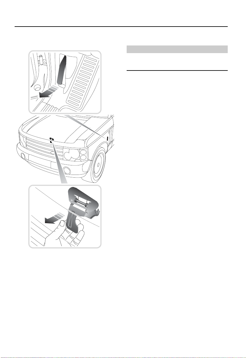
HOOD OPENING
Closing the hood
WARNING
DO NOT drive with the hood retained by the
safety catch alone.
After closing the hood, check that the lock is
fully engaged by attempting to lift the front edge
of the hood. This should be free from all
movement.
H3987
1. From inside the vehicle on the driver’s
side, pull the hood release handle (see
upper inset).
2. Lift the hood safety catch lever (lower
inset) and raise the hood.
198
Page 9
WWW.MANUALS.WS
WWW.MANUALS.WS
Engine Compartment
Engine Compartme nt
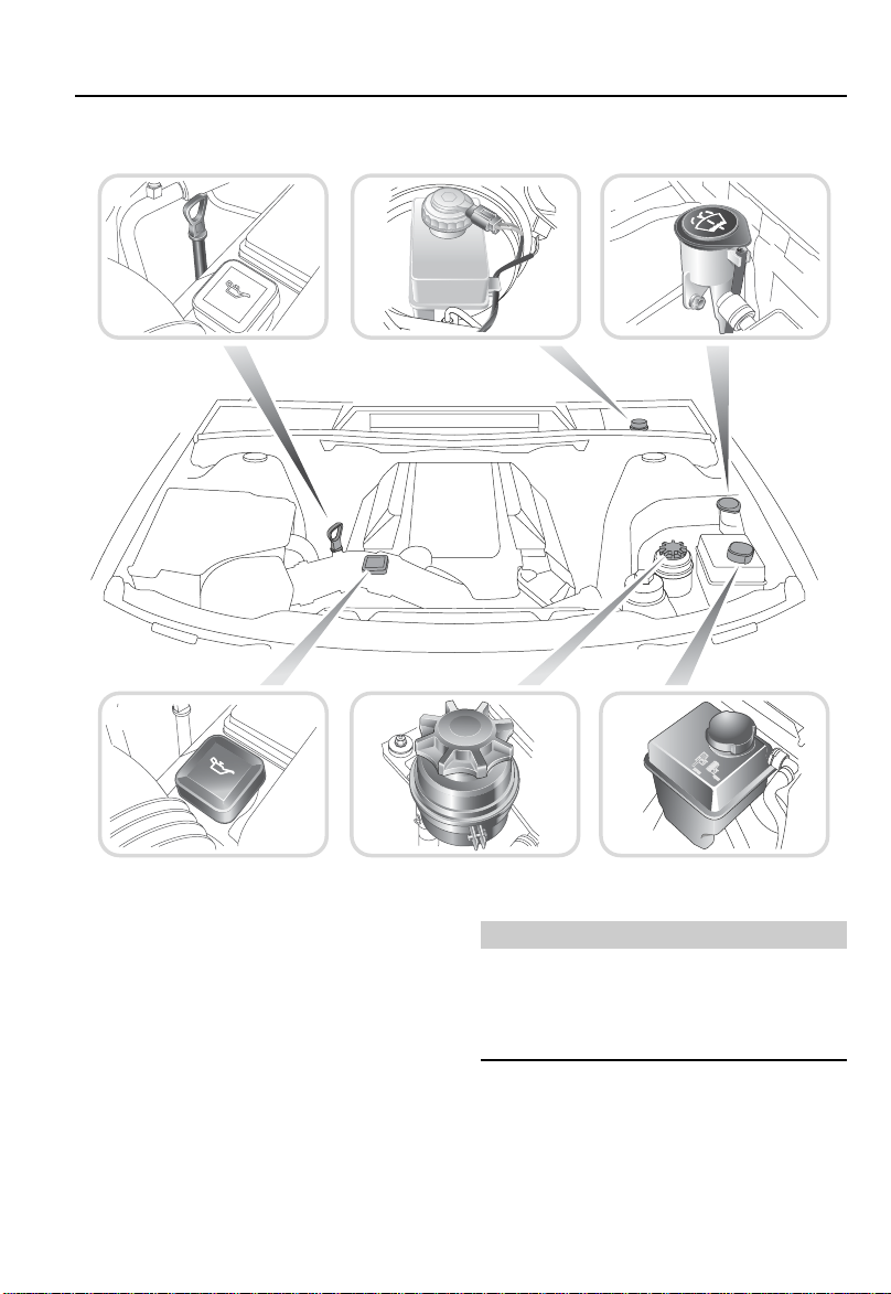
FLUID RESERVOIR LOCATIONS
1 2
3
4
5 6
H3905
1. Engine oil dipstick.
2. Brake fluid reservoir.
3. Washer reservoir.
4. Engine oil filler cap.
5. Power steering reservoir.
6. Cooling system reservoir.
WARNING
To avoid serious injury or death, while
working in the engine compartment, ALWAYS
observe the safety precautions listed under
‘SAFETY IN THE GARAGE’, page 196
199
Page 10
WWW.MANUALS.WS
WWW.MANUALS.WS
Engine Oil
Engine Oil
CHECK & TOP-UP
Check the oil level at least every 250 miles
(400 km), when the engine is COLD and with
the vehicle resting on level ground.
NOTE: If it is necessary to check the oil level
when the engine is hot, switch off the engine
and let the vehicle stand for five minutes to
allow the oil to drain back into the sump. DO
NOT start the engine.
As a general guide, if the level on the dipstick:
• is nearer to the upper mark than the lower,
add no oil.
• is nearer to the lower mark than the upper,
add half a quart of oil.
• is below the lower mark, add one quart of oil
and re-check the level after a further five
minutes.
Oil specification
It is essential to use an oil suitable for the
climatic conditions in which the vehicle is to be
operated. Precise specifications are shown in
‘LUBRICANTS AND FLUIDS’, page 271. If in
doubt, contact your Land Rover retailer.
H3961
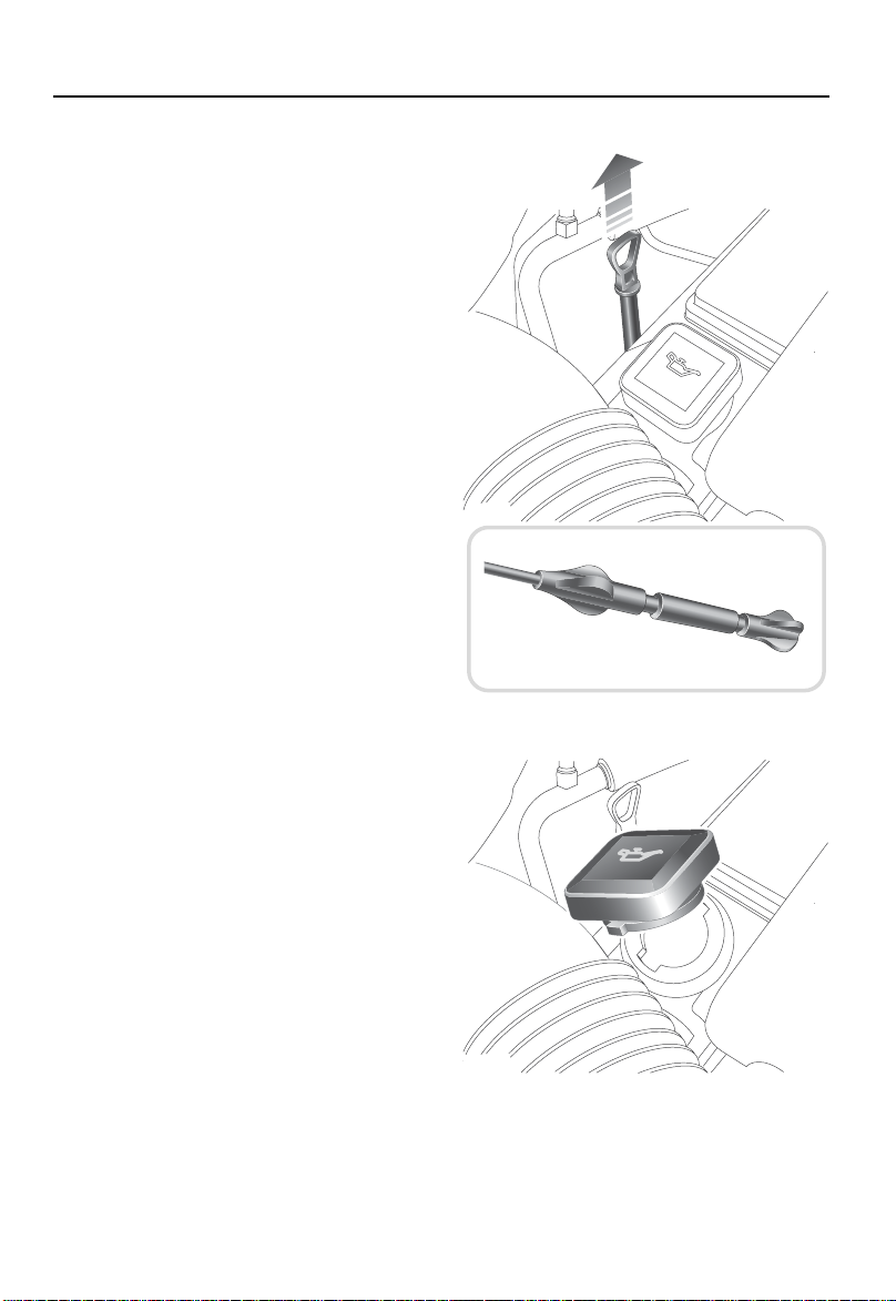
Topping-up
1. Withdraw the dipstick and wipe the blade
clean.
2. Fully re-insert the dipstick and withdraw
again to check the level, which should
NEVER be allowed to fall below the lower
mark on the dipstick.
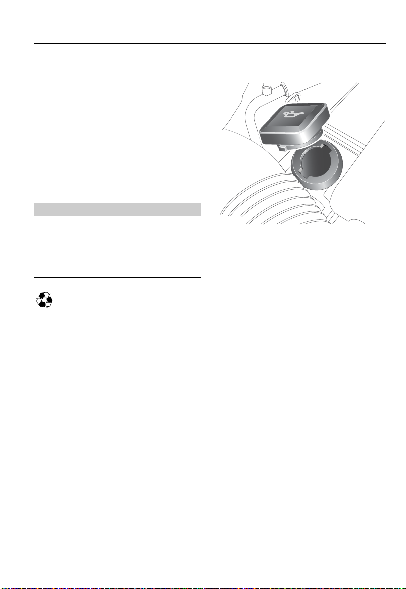
3. To top-up, unscrew the oil filler cap and
add oil to maintain the level between the
UPPER and LOWER marks on the dipstick.
DO NOT OVERFILL!
Oil levels above the MAX mark may cause
engine damage. Some oil must be removed
from the engine by a service technician.
H3960
200
Page 11
WWW.MANUALS.WS
WWW.MANUALS.WS
Engine Oil
DRAIN & REFILL
Ensure that the engine oil is changed at the
recommended service intervals as specified in
the Passport to Service book.
NOTE: Under severe operating conditions
(i.e. regular use in muddy terrain or dusty
conditions), the engine oil must be changed
more frequently, even to the extent of a daily
change. Consult your Land Rover retailer for
guidance.
Used engine oil
WARNING
Prolonged contact with used engine oil can
cause serious skin disorders, including
dermatitis and cancer of the skin. Wear
protective clothing if possible and ALWAYS
wash thoroughly after contact.
It is illegal to pollute drains, water courses
or soil with toxic chemicals such as used
engine oil. Use authorised waste disposal sites
to dispose of used oil and toxic chemicals.
Drain
H4684
With the engine warm (to assist oil drainage)
and the vehicle parked on firm, level ground,
remove the filler cap and position a container of
suitable size (at least 10 US quarts or 10 litres)
under the drain plug, in the bottom of the sump.
It is assumed that the engine oil filter will be
renewed at the same time as draining and
refilling the engine oil.
Because any used engine oil remaining in the
filter container will drain into the sump when
the filter is changed, it is better to change the
filter element (see ‘Oil filter renewal’, page 203)
before draining and refilling the engine oil.
201
Page 12
WWW.MANUALS.WS
WWW.MANUALS.WS
Engine Oil
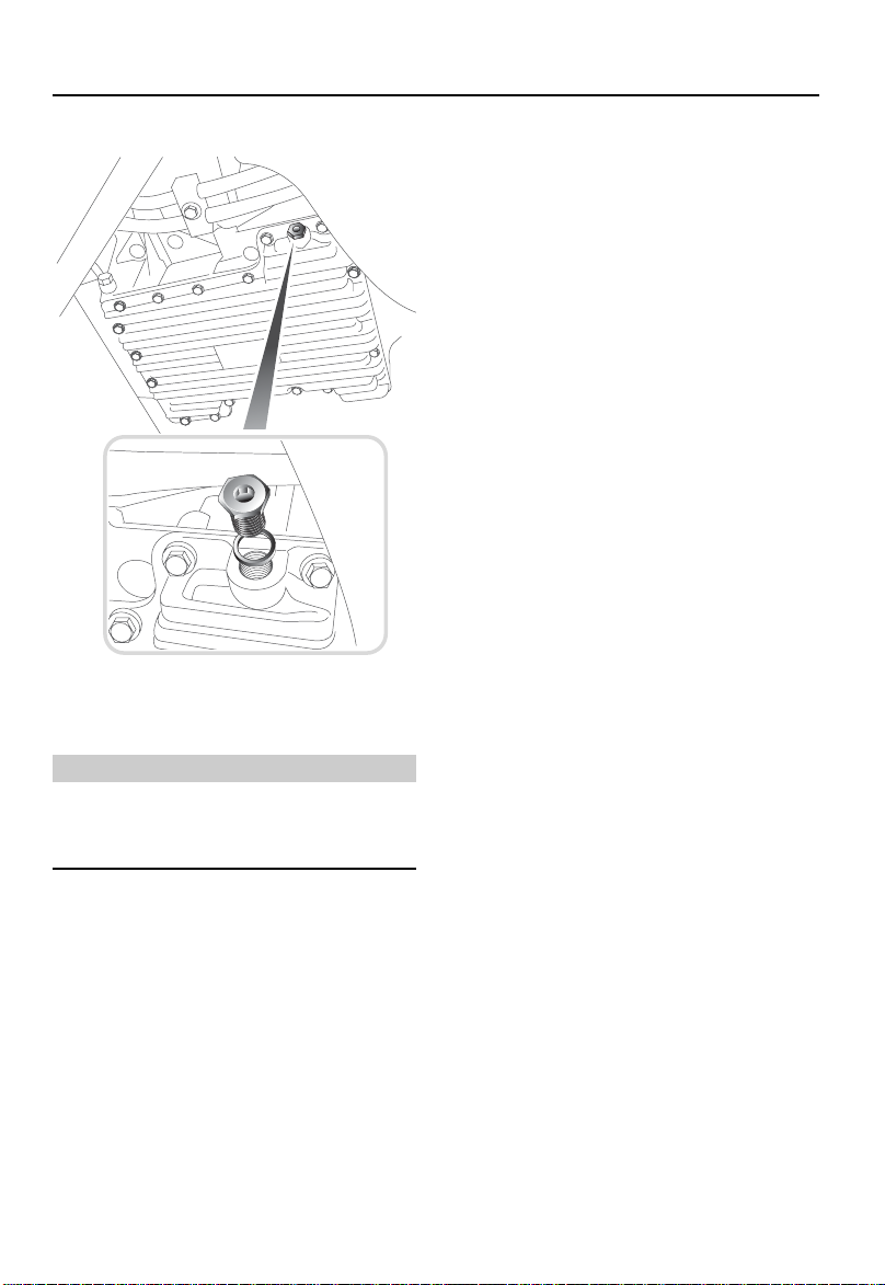
Refill
H4685
Remove the drain plug and copper washer and
allow the engine oil to drain into the container.
WARNING
Oil from the engine can be very hot, to avoid
harmful burns, take care when removing the
drain plug.
Clean the oil drain plug and its mating surface
on the engine sump. Fit the drain plug,
complete with a new copper washer, and
tighten to 13 lbf.ft (17 Nm).
Refill the engine with fresh oil, suitable for the
climatic conditions in which the vehicle is to be
operated (see ‘LUBRICANTS AND FLUIDS’,
page 271).
DO NOT overfill the engine! Remember that a
little oil will always remain in the engine after
draining and that, therefore, the quantity of oil
required to refill the engine will be slightly less
than the full capacity quoted in ‘CAPACITIES’,
page 272.
After filling, allow a few minutes to elapse
before checking the level on the dipstick (this
will allow all the oil to drain into the sump and
enable a true reading to be obtained). Once the
correct level of oil is shown on the dipstick,
replace the filler cap.
Start and run the engine. Do not rev the engine
until the oil pressure warning light
extinguishes. Check for oil leaks around the
drain plug.
Stop the engine, wait a few minutes, then check
the oil level and top up if necessary.
202
Page 13
WWW.MANUALS.WS
WWW.MANUALS.WS
Engine Oil
Oil filter renewal
H4687
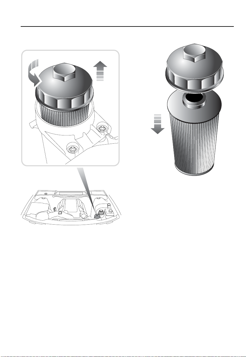
6. Attach the cap to the new filter element by
pushing it onto the end of the element.
7. Insert the element into the filter body and
H4686
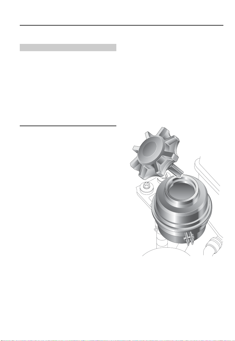
The engine oil filter is located at the front of the
engine compartment.
1. Unscrew the filter cap anti-clockwise and
raise it slightly. The filter element will be
withdrawn by the cap.
2. Allow a few moments for the engine oil
retained within the filter body to drain
away.
3. With a suitable container handy, fully lift
off the cap and element together and place
them in the container.
4. Pull the cap from the element and clean it.
5. Clean the inside of the filter body.
203
screw down the cap. Tighten to 18 lbf.ft
(25 Nm)
8. Start and run the engine. Do not rev the
engine until the oil pressure warning light
extinguishes. Check for oil leaks around
the filter body.
9. Stop the engine, wait a few minutes, then
check the oil level and top up if necessary.
Page 14
WWW.MANUALS.WS
WWW.MANUALS.WS
Air Cleaner
Air Cleaner
ELEMENT RENEWAL
Renewing the air cleaner element at the
recommended service intervals (see your
‘Passport to Service book’) is extremely
important. However, to maintain optimum
engine performance under dusty operating
conditions, more frequent renewal will be
necessary. Consult your retailer for guidance.
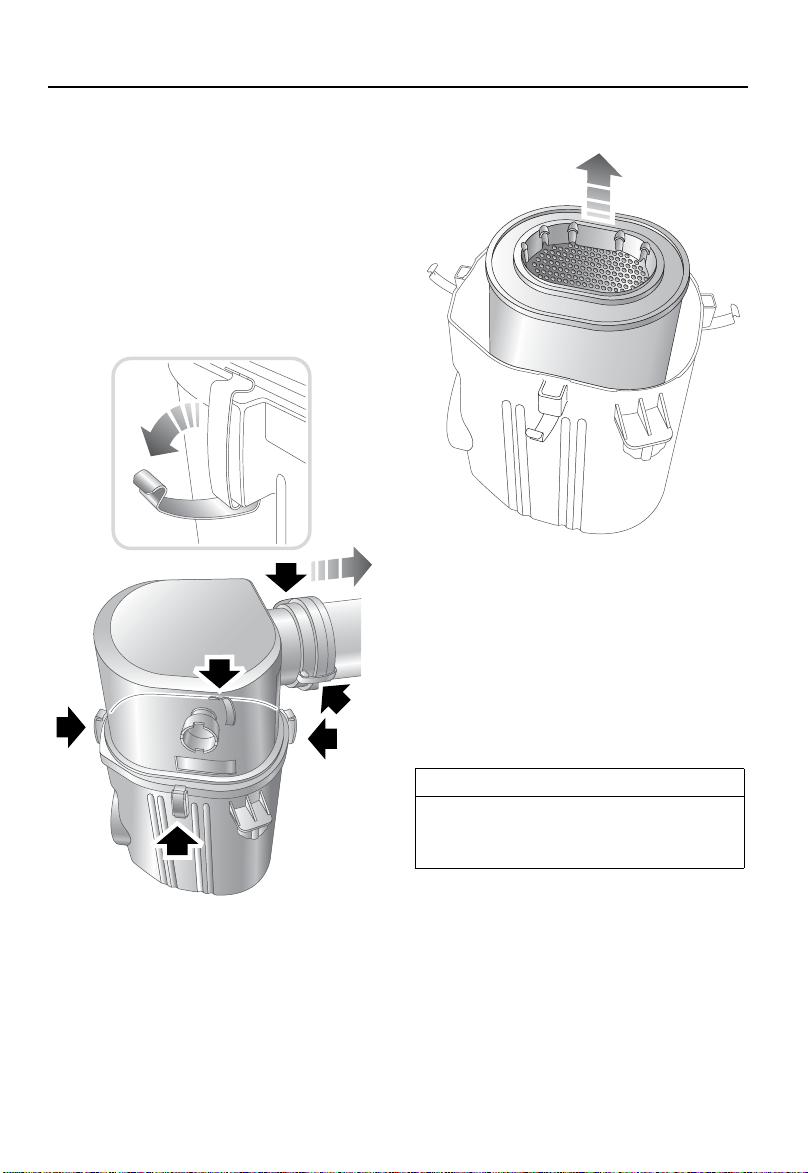
H4689
3. Remove and discard the air cleaner
element, noting which way up the element
fits. Before fitting a new element, clean the
inside of the air cleaner body and cover.
4. Fit the new air cleaner element and cover
and secure the catches.
5. Connect the hose to the rear of the air
cleaner and secure the catches.
IMPORTANT INFORMATION
Always fit a NEW element; under no
circumstances should a contaminated
element be cleaned and used again.
H4688
1. Release 2 catches securing the hose to the
rear of the air cleaner; detach the hose.
2. Release 4 catches securing the cover to
the air cleaner body and remove the cover
to gain access to the element.
204
Page 15

WWW.MANUALS.WS
WWW.MANUALS.WS
Spark Plugs
Spark Plugs
SPARK PLUG REMOVE & REFIT
Spark plug removal
1. Disconnect the battery - ensuring that all
text and cautions in the relevant section of
the handbook (see ‘BATTERY SAFETY’,
page 215) are observed.
3. Working on one side of the engine,
remove 2 bolt access covers from the
ignition coil covers and remove the bolts
beneath them.
H4679
2. Release 4 Allen head turnbuckles and
remove the acoustic cover, see above.
H4680
4. Remove the ignition coil cover.
5. Remove 2 bolt spacers from the ignition
coil covers.
6. Repeat steps 3 to 5 for the other side of
the engine.
205
Page 16
WWW.MANUALS.WS
WWW.MANUALS.WS
Spark Plugs
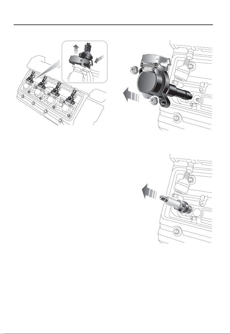
H4681
7. Remove 2 nuts and disconnect the wiring
harness and camshaft cover earth leads.
8. Disconnect 8 multiplugs from their
ignition coils by pulling up each metal
locking clamp.
9. Discard both ignition coil cover gaskets.
10. Remove 14 nuts securing the ignition
coils.
H4682
11. Pull out 8 ignition coil units.
H4683
12. Clean the area around each spark plug
and, using a suitable spark plug wrench,
remove 8 spark plugs.
206
Page 17

WWW.MANUALS.WS
WWW.MANUALS.WS
Spark Plugs
Fitting new spark plugs
When fitting new spark plugs, take care not to
cross-thread a plug, otherwise costly damage
to the cylinder head will result.
Only fit plugs of a type recommended by Land
Rover (see ‘V8 ENGINE’, page 273). Please
note that fitting incorrect grades of plug may
lead to engine failure and serious damage.
1. Fit 8 new spark plugs and tighten to a
torque of 23 lbf.ft (31 Nm).
2. Fit an ignition coil to each plug.
3. Fit 14 nuts securing the ignition coils and
tighten them to 3 lbf.ft (4 Nm).
4. Fit 2 new ignition coil cover gaskets
5. Connect each multiplug to its ignition coil
and lock in position by pressing down
each locking clamp.
6. Reposition the wiring harness and
camshaft cover earth leads, fit the
remaining 2 nuts and tighten to 3 lbf.ft
(4 Nm).
7. Fit 2 bolt spacers to each ignition coil
cover.
8. Fit both ignition coil covers, tighten the
bolts and refit the 4 bolt access covers.
9. Refit the engine acoustic cover.
10. Reconnect the battery.
207
Page 18
WWW.MANUALS.WS
WWW.MANUALS.WS
Cooling System
Cooling System
COOLANT CHECK AND TOP-UP
WARNING
NEVER remove the filler cap when the engine
is hot -escaping steam or scalding water
could cause serious personal injury.
Unscrew the filler cap slowly, allowing the
pressure to escape before removing
completely.
Avoid spilling anti-freeze onto a hot engine a fire may result.
CAUTION: NEVER run the engine without
coolant.
CAUTION: NEVER top-up with salt water. When
travelling in territories where the water supply
contains salt, always ensure that you carry a
supply of fresh (rain or distilled) water.
NOTE: Anti-freeze will damage painted
surfaces: Soak up any spillage with an
absorbent cloth immediately and wash the area
with a mixture of car shampoo and water.
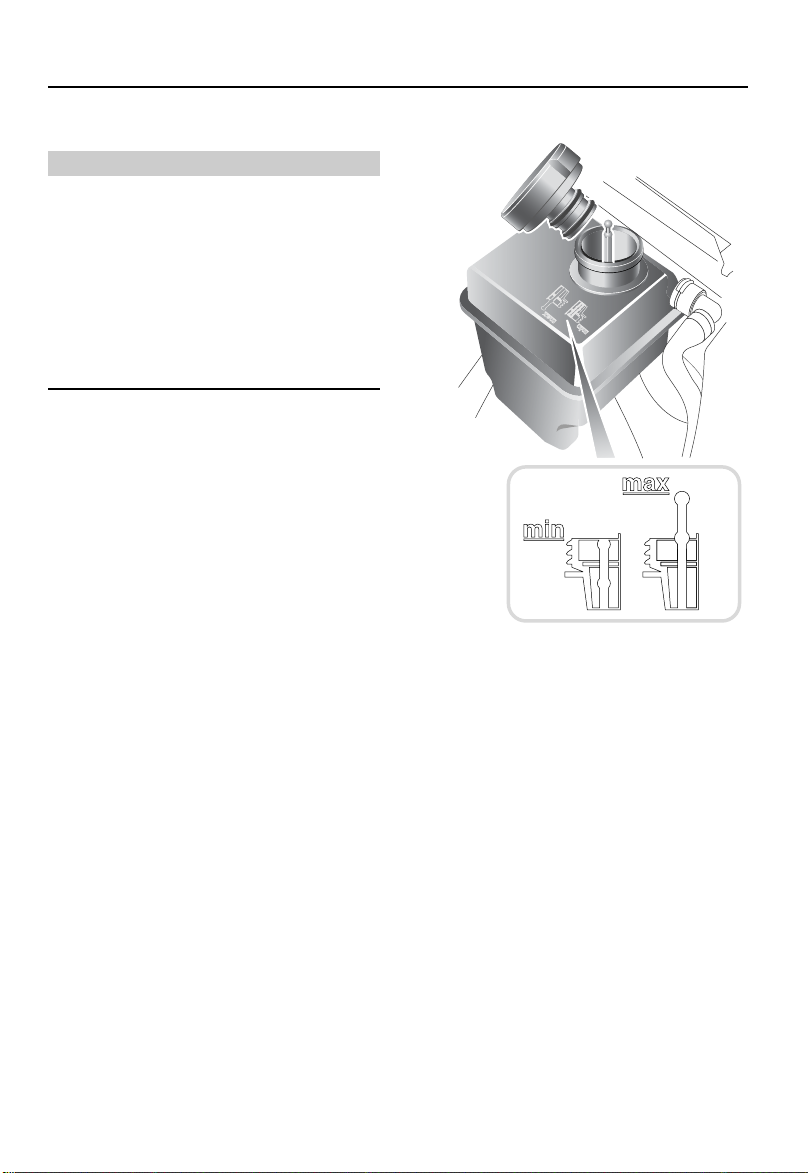
The coolant level in the expansion tank should
only be checked and topped-up if low level
indication is given in the message centre.
Always check the level WHEN THE SYSTEM IS
COLD.
If it is necessary to remove the filler cap before
the system has fully cooled, loosen the cap
slowly, allowing the air pressure to escape
gradually.
H3908
Top-up with a 50% mixture of anti-freeze and
water so that the float protrudes slightly from
the filler neck, in accordance with the
illustration inset. DO NOT OVERFILL!
Ensure the cap is tightened fully after top-up is
completed.
If the level has fallen appreciably, suspect
leakage or overheating and arrange for your
retailer to examine the vehicle.
CAUTION: An over-filled expansion tank may
cause a build-up of pressure and excess fluid
could be expelled through the filler cap.
208
Page 19

WWW.MANUALS.WS
WWW.MANUALS.WS
Cooling System
ANTI-FREEZE
WARNING
Anti-freeze is poisonous and can be fatal if
swallowed - keep containers sealed and out
of the reach of children. If accidental
consumption is suspected, seek medical
attention immediately.
Prevent anti-freeze coming in contact with the
skin or eyes. If this occurs, rinse immediately
with plenty of water.
Anti-freeze contains important corrosion
inhibitors. The anti-freeze content of the
coolant must be maintained at 50% ± 5% all
year round (not just in cold conditions). To
ensure that the anti-corrosion properties of the
coolant are retained, the anti-freeze content
should be checked once a year and completely
renewed every 4 years, regardless of distance
travelled. Failure to do so may cause corrosion
of the radiator and engine components.
The specific gravity of a 50% anti-freeze
solution at 68ºF (20°C) is 1.075 and protects
against frost down to -33ºF (-36°C).
Coolant specification
Use ONLY a 50% mix of water and Castrol
Anti-freeze NF or approved alternative. See
‘LUBRICANTS AND FLUIDS’, page 271.
In an emergency - and only if this type of
anti-freeze is unavailable - top-up the cooling
system with clean water, but be aware of the
resultant reduction in frost protection. DO NOT
top-up or refill with conventional anti-freeze
formulations. If in doubt consult a Land Rover
retailer.
NOTE: When clean water is added in the event
of an emergency, the low coolant light will
illuminate if the water/anti-freeze mix ratio is
over-diluted. This light will extinguish when the
ratio of water/anti-freeze is returned to a 50%
mix. This should be done at the earliest
opportunity.
209
Page 20
WWW.MANUALS.WS
WWW.MANUALS.WS
Brakes
MAX
MIN
Brakes
BRAKE FLUID
Top-up
WARNING
Brake fluid is highly toxic - keep containers
sealed and out of the reach of children. If
accidental consumption of fluid is suspected,
seek medical attention immediately.
If brake fluid should come into contact with
the skin or eyes, rinse immediately with
plenty of water.
Take care not to spill fluid onto a hot engine a fire may result.
CAUTION: DO NOT drive the vehicle with the
fluid level below the ‘MIN’ mark.
NOTE: Brake fluid will damage painted
surfaces: Soak up any spillage with an
absorbent cloth immediately and wash the area
with a mixture of car shampoo and water.
Check
The fluid level may fall slightly during normal
use as a result of brake pad wear but should not
be allowed to fall below the ‘MIN’ mark. Any
substantial drop in fluid indicates a leak in the
system, in which case the vehicle must NOT be
driven and you should contact your retailer.
WARNING
Contact your retailer immediately if brake
pedal travel is unusually long or if there is any
appreciable drop in brake fluid level.
H4226
Wipe the filler cap clean before removing to
prevent dirt from entering the reservoir.
Unscrew the cap (1/8 turn) and top-up the
reservoir to the ‘MAX’ mark using brake fluid
conforming to DOT 4 specification.
Use only new fluid from an airtight container
(old fluid from opened containers or fluid
previously bled from the system will have
absorbed moisture, which will adversely affect
performance, and must NOT be used). DO NOT
OVERFILL!
Brake fluid must be completely renewed every
3 years, regardless of distance travelled.
With the vehicle on level ground, check the fluid
level at least every week (more frequently in
high mileage or arduous operating conditions).
Check the level visually through the side of the
transparent reservoir without removing the
filler cap.
210
Page 21
WWW.MANUALS.WS
WWW.MANUALS.WS
Power Steering
Power Steering
POWER STEERING FLUID
WARNING
Power steering fluid is highly toxic - keep
containers sealed and out of reach of
children. If accidental consumption of fluid is
suspected, seek medical attention
immediately.
If power steering fluid should come into
contact with the skin or eyes, rinse
immediately with plenty of water.
Do not spill power steering fluid onto a hot
engine - a fire may result.
NOTE: Power steering fluid will damage painted
surfaces: Soak up any spillage with an
absorbent cloth immediately and wash the area
with a mixture of car shampoo and water.
Emergency operation
Any large or sudden drop in the fluid level must
be investigated by a qualified retailer.
If it can be established that fluid loss is slow,
then the reservoir may be topped-up to the
upper level mark to enable the vehicle to be
driven to the nearest qualified retailer for
examination.
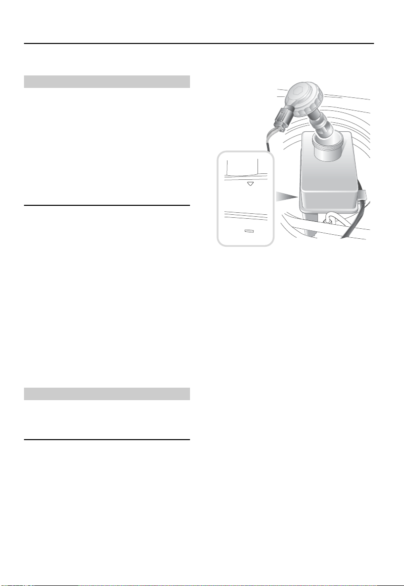
Check and Top-up
Check and top-up the fluid level ONLY with the
engine switched off and the system cold, and
ensure that the steering wheel is not turned
after stopping the engine.
Wipe the filler cap clean to prevent dirt from
entering the reservoir. Remove the filler cap
and, using a lint-free cloth, wipe the dipstick
clean. Refit the filler cap fully and remove it
again to check the fluid level. Add fluid to the
reservoir until the level is between the upper
mark and the bottom of the dipstick. DO NOT
fill above the upper mark on the dipstick.
If the fluid level has dropped below the lower
level mark, top-up the reservoir before starting
the engine, or damage to the steering pump
could result.
CAUTION: The engine must NOT be started if
the fluid level has dropped below the bottom of
the dipstick - severe damage to the pump could
result.
H3967
211
Page 22
WWW.MANUALS.WS
WWW.MANUALS.WS
Washers
Washers
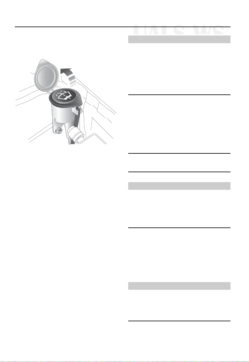
WINDSHIELD WASHERS
Fluid top-up
H3909
The windshield washer reservoir supplies both
windshield and rear window washer jets.
Check the reservoir level at least every week
and to prevent freezing in cold weather, top-up
with a mixture of water and a recommended
screenwash.
Preferably mix the recommended quantities of
water and screenwash in a separate container
before topping-up the system, and always
follow the instructions on the screenwash
container.
CAUTION: State or local regulations on volatile
organic compounds may restrict the use of
methanol, a common windshield washer
anti-freeze additive. Washer fluids containing
non-methanol anti-freeze agents should be
used only if they provide cold weather
protection without damaging the vehicle’s paint
finish, wiper blades or washer system.
If you operate your vehicle in temperatures
below 40 degrees F, use washer fluid with
anti-freeze protection. In cold weather,
failure to use washer fluid with anti-freeze
protection could result in impaired
windshield vision and increase the risk of a
vehicle crash.
CAUTION: DO NOT use an anti-freeze or
vinegar/water solution in the washer reservoir anti-freeze will damage painted surfaces, while
vinegar can damage the windshield washer
pump.
Screenwash
Use Land Rover Parts STC8249 screenwash, or
any good quality proprietary screenwash.
Some screenwash products are inflammable,
particularly if high or undiluted
concentrations are exposed to sparking. Do
not allow screenwash to come into contact
with naked flames or sources of ignition.
NOTE: Body panels may suffer discoloration as
a result of screenwash spillage.Take care to
avoid spillage, particularly if an undiluted or
high concentration of screenwash is being
used. If spillage occurs, wash the affected area
immediately with water.
Do not put engine coolant in the windscreen
washer fluid reservoir. If engine coolant is
sprayed onto the windscreen, it could make it
difficult to see through the windscreen.
WARNING
WARNING
WARNING
212
Page 23

WWW.MANUALS.WS
WWW.MANUALS.WS
Washers
Washer jets
Operate the washer switches periodically to
check that the nozzles are clear and properly
directed.
The windshield washer jets are set during
manufacture and should not need adjusting.
However, if adjustment is ever necessary, insert
a needle into the jet orifice and lever gently to
position each jet so that the spray is directed
towards the center of the windshield.
Should a windshield washer jet become
obstructed, insert a needle or thin strand of wire
into the orifice to clear the blockage.
NOTE: The rear screen washer jet is integral
with the wiper arm and requires no adjustment.
HEADLIGHT WASHERS*
The spray jets are set during manufacture and
should not need to be adjusted.
213
Page 24
WWW.MANUALS.WS
WWW.MANUALS.WS
Wiper Blades
Wiper Blades
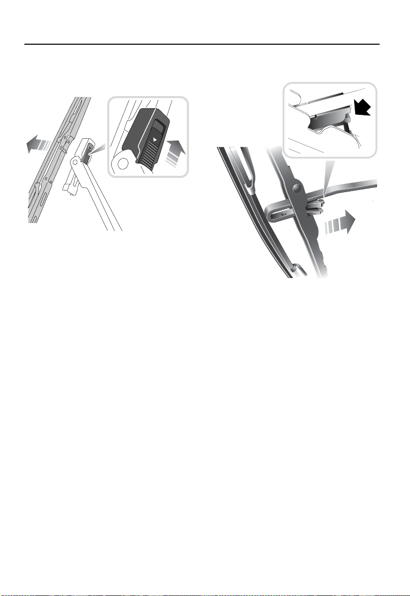
WIPER BLADE REPLACEMENT
Front wiper blades
LOCK
LOCK
Rear wiper blade
H3912
Lift the wiper arm away from the windshield.
Disconnect the blade by pushing the locking tab
(see inset in illustration) to the unlock position.
Fitting a replacement blade is a reversal of this
process. Check that the blade is securely locked
before returning the wiper assembly to the
windshield.
Only fit replacement wiper blades that are
identical to the original specification.
Grease, silicone and petroleum-based products
impair the blade's wiping capability. Wash the
wiper blades in warm soapy water and
periodically check their condition.
If signs of hardness or cracking in the rubber
are found, or if the wipers leave streaks or
unwiped areas on the windshield during use,
then the wiper blades should be replaced.
Clean the windshield regularly with an approved
glass cleaner and ensure the windshield is
thoroughly cleaned before fitting replacement
wiper blades.
H3913
Lift the wiper arm away from the rear window
and pivot the blade assembly away from the
arm. Press the tab (arrowed in inset), to release
the blade assembly and slide the assembly off
the end of the wiper arm. Carefully replace the
arm to its stowed position.
To replace, position the wiper arm into the
aperture in the middle of the blade assembly
and push firmly into position until the blade
clips into place.
Headlight wiper blade
The headlight wiper blade and wiper arm are an
integral unit and should only be replaced by
qualified personnel.
214
Page 25
WWW.MANUALS.WS
WWW.MANUALS.WS
Battery
Battery
BATTERY SAFETY
BATTERY MAINTENANCE
WARNING
ALWAYS wear appropriate eye protection
when working around batteries.
Batteries contain acid, which is both
corrosive and poisonous. If spillage occurs:
•
On clothing or the skin - remove any
contaminated clothing immediately, flush
the skin with large amounts of water, and
seek medical attention urgently.
•
In the eyes - flush with clean water
immediately for at least 15 minutes. Seek
medical attention urgently.
•
Swallowing battery acid can be fatal
unless IMMEDIATE action is taken - seek
medical attention urgently.
During normal operation batteries emit
explosive hydrogen gas - to avoid fire, ensure
sparks and naked lights are kept away from
the engine compartment.
For your safety, remove all metal wrist bands
and jewellery before working in the engine
compartment and NEVER allow the battery
terminals or vehicle leads to make contact
with tools or metal parts of the vehicle.
WARNING
Battery posts, terminals and related
accessories contain lead and lead
compounds. Wash hands after handling.
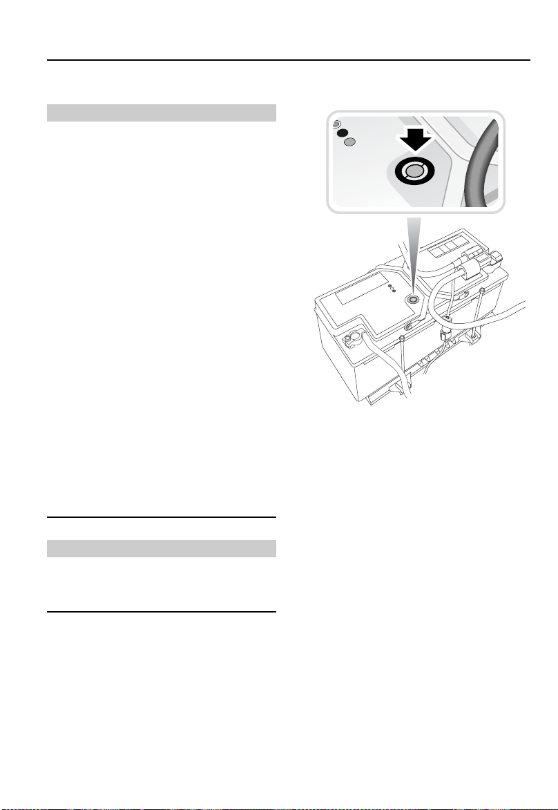
H3997
The battery is designed to be maintenance free,
so topping-up is unnecessary. On the top of the
battery there is a battery condition indicator
(arrowed in inset). Examine the indicator
periodically to check the battery's condition.
When the indicator shows:
• GREEN - the battery is in a good state of
charge.
• DARK (turning to black) - the battery needs
charging.
• CLEAR (or light yellow) - the battery must
be replaced. Do not charge the battery or
jump start the vehicle in this condition.
NOTE: When checking the battery condition
indicator, if necessary, clean the battery top to
ensure a clear view.
215
Page 26

WWW.MANUALS.WS
WWW.MANUALS.WS
Battery
If the indicator shows clear or yellow, tap the
indicator with the handle of a screwdriver to
disperse any air bubbles. If the color is
unchanged, the battery must be replaced.
Battery disconnection, charging, removal and
replacement
There may at times be a requirement to
disconnect the battery, eg, to necessitate
Interlock Code emergency deactivation - see
your Audio & Navigation handbook.
• Turn the starter switch off and remove the
starter key.
• Wait for at least two minutes before starting
the disconnection procedure. Ensure you
have your remote handset available as you
may have to turn off the alarm sounder.
• Disconnect ONLY the negative (‘-’) terminal.
• Wait for two minutes before reconnecting
the battery.
If the alarm sounds when the battery is
reconnected, use the key fob to turn it off.
WARNING
The battery positive (‘+’) terminal is fitted
with a pyrotechnic charge, designed to
disconnect the battery as a safety precaution
in the event of a severe collision. For this
reason, the battery charging, disconnection
and removal should only be attempted by
qualified personnel.
Effects of battery disconnection
Following disconnection and subsequent
reconnection of the vehicle battery, a number of
the vehicle systems will be reset automatically.
This may take a few minutes and with some
systems, sensors have to detect certain actions
whilst driving before full operability returns.
This in no way affects the safe operation of the
vehicle.
Replacement batteries
Only fit a replacement battery of the same
type and specification as the original - other
batteries may vary in size or have different
terminal positions which could cause a fire
hazard when connected to the vehicle’s
electrical system.
Battery disposal
Used batteries should be recycled.
However, batteries are hazardous - you
should seek advice about disposal from a Land
Rover retailer or your local authority.
WARNING
WARNING
Battery posts, terminals and related
accessories contain lead and lead
compounds. Wash hands after handling.
216
Page 27

WWW.MANUALS.WS
WWW.MANUALS.WS
Tires
Tires
CARING FOR YOUR TIRES
WARNING
DEFECTIVE TIRES ARE DANGEROUS! Do not
drive if any tire is damaged, is excessively
worn, or is inflated to an incorrect pressure.
ALWAYS replace worn or defective tires with
the factory recommended specification (see
‘WHEELS & TIRES’, page 276). Failure to do
so may affect the safe handling of the vehicle.
Always drive with consideration for the
condition of the tires, and regularly inspect the
tread and side walls for any sign of distortion
(bulges), cuts or wear.
The most common causes of tire failure are:
• Bumping against curbs
• Driving over deep potholes in the road.
• Driving with under- or over-inflated tires
NOTE: If possible, protect tires from
contamination by oil, grease, fuel and other
automotive fluids.
Safety practices
The way you drive has a great deal to do with
your tire mileage and safety. Cultivate good
driving habits for your own benefit.
• Observe posted speed limits
• Avoid fast starts, stops and turns
• Avoid potholes and objects on the road
• Do not run over curbs or hit the tire against
the curb when parking
• Avoid wheel spin
Avoid tire spinning. The forces created by
rapidly spinning a tire can cause failure of, or
damage to, the tire structure.
If a tire does spin, never exceed the 35 mph
point indicated on the speedometer.
Do not allow anyone to stand near, or directly
in line with, a tire that may spin.
Tire pressures
Correctly inflated tires will ensure that you
enjoy the best combination of tire life, ride
comfort, fuel economy and road handling.
Under-inflated tires wear more rapidly, can
seriously affect the vehicle's road handling
characteristics and fuel consumption, as well
as increase the risk of tire failure. Over-inflated
tires give a harsher ride, wear unevenly and are
more prone to damage.
Tire pressures should be checked at least once
a week with normal road use, but should be
checked DAILY if the vehicle is used off-road.
Check the pressures (including the spare
wheel) when the tires are cold - be aware that it
only takes 3 miles (5 km) of driving to warm the
tires sufficiently to affect the tire pressures.
NOTE: Air pressure naturally increases in warm
tires. If it is necessary to check the tires when
they are warm (after the vehicle has been driven
for a while), the pressure may have increased
by up to 6 lbf/in
NEVER let air out of the tire in order to match
the recommended pressures.
WARNING
2
(41 kPa). In this circumstance,
217
Page 28

WWW.MANUALS.WS
WWW.MANUALS.WS
Tires
If the vehicle has been parked in strong
sunlight or used in high ambient
temperatures, DO NOT reduce tire pressures;
instead, move the vehicle into the shade and
allow the tires to cool before checking.
The recommended pressures for cold tires are
shown in ‘WHEELS & TIRES’, page 276.
Use a tire gauge to check the tire inflation
pressures, including the spare, at least weekly
and before long journeys. Land Rover strongly
recommends using a reliable tire pressure
gauge, as automatic service station gauges
may be inaccurate.
WARNING
5. Replace the valve cap.
6. Repeat with each tire.
NOTE: The pressure for your spare tire should
be set to the highest value given for your
wheel/tire size combination, and adjusted after
fitment.
7. Visually inspect the tires to make sure that
there are no nails or other objects
embedded in them.
8. Check the sidewalls to make sure that
there are no gouges, cuts, bulges or other
irregularities.
Checking tire inflation pressures
Check the tire inflation pressure when the tires
are cold, i.e. before driving.
1. Remove the cap from the valve on one tire.
2. Firmly press a tire gauge onto the valve.
3. Add air to achieve the recommended tire
pressure.
4. If you overfill the tire, release air by
pushing on the metal stem in the center of
the valve. Then recheck the pressure with
your tire gauge.
NOTE: Tire pressure increases in warm weather
and decreases in cold weather.
218
Page 29

WWW.MANUALS.WS
WWW.MANUALS.WS
Tires
Tire wear
H4942
Tires fitted as original equipment have wear
indicators moulded into the tread pattern.
When the tread has worn down to 1/16 inch
(1.6 mm) the indicators start appearing at the
surface of the tread pattern, producing the
effect of a continuous band of rubber across the
width of the tire.
A tire MUST be replaced as soon as an indicator
band becomes visible or the tread depth
reaches the minimum permitted by legislation
in the market you are driving in.
Tread depth must be checked regularly (at
every maintenance service, or more
frequently). Always replace a tire before the
tread reaches a remaining depth of 1/16 inch
(1.6 mm). DO NOT drive with tires worn to this
limit, the safety of the vehicle and occupants
will be adversely affected.
NOTE: After off-road use, check to make sure
there are no lumps, cuts or bulges in the tires
or exposure of the ply or cord structure.
Valves
Keep the valve caps screwed down firmly - they
prevent dirt from entering the valve. Check the
valve for leaks (listen for a tell-tale hissing)
when you check the tire pressure.
Punctured tires
Your vehicle is fitted with tubeless tires, which
may not leak immediately if penetrated by a
sharp object, provided the object remains in the
tire.
A puncture of this kind will eventually cause the
tire to lose pressure, which is why regular (and
frequent) checking of tire pressures is
important. Punctured or damaged tires must be
permanently repaired, where possible within
industry legislation by a qualified technician, or
replaced as soon as possible.
If you sustain a puncture, reduce driving speed
immediately in a straight line where possible,
whilst avoiding heavy braking or sharp steering
inputs. Pull over at the first safe place possible
to change your tire.
Highway hazards
No matter how carefully you drive, there is
always the possibility of a puncture on the
highway. In this event, drive slowly to the
closest safe area out of traffic. This may further
damage the flat tire, but your safety is more
important.
If you feel a sudden vibration or ride
disturbance while driving, or you suspect that
your tire or vehicle has been damaged,
immediately reduce your speed. Drive with
caution and safely pull off the road at the
earliest opportunity. Stop and inspect the tire
for damage. If the tire is under-inflated or
damaged, remove the tire and wheel and
replace it with your spare. If you cannot detect
a cause, have the vehicle towed to the nearest
vehicle or tire retailer to have the vehicle
inspected.
219
Page 30

WWW.MANUALS.WS
WWW.MANUALS.WS
Tires
Replacement tires
WARNING
Wheels and tires are matched to suit the
handling characteristics of the vehicle. For
safety, ALWAYS check that replacement tires
comply with the original specification (see
‘WHEELS & TIRES’, page 276) and that the
load and speed ratings shown on the side wall
are the same as that of the original
equipment. Contact your Land Rover retailer
for further information or assistance.
UNIFORM TIRE QUALITY GRADING
Quality Grades can be found where applicable
on the tire sidewall between tread shoulder and
maximum section width. For example:
Treadwear 200 Traction AA Temperature A
Tires that are deep tread, winter-type snow tires
are exempt from the marking requirements as
described above. Consequently, the tires fitted
to your vehicle may not carry these markings.
All passenger car tires must conform to Federal
Safety Requirements in addition to these
grades.
Treadwear
The treadwear grade is a comparative rating
based on the wear rate of the tire when tested
under controlled conditions on a specified
government test course. For example; a tire
graded 150 would wear one and one-half (1½)
times as well on the government course as a
tire graded 100. The relative performance of
tires depends upon the actual conditions of
their use however, and may depart significantly
from the norm due to variations in driving
habits, service practices and differences in road
characteristics and climate.
220
Page 31

WWW.MANUALS.WS
WWW.MANUALS.WS
Tires
Traction
The traction grades, from highest to lowest, are
AA, A, B and C. The grades represent a tire's
ability to stop on wet pavement as measured
under controlled conditions on specified
government test surfaces of asphalt and
concrete. A tire marked 'C' may have poor
traction performance.
WARNING
The traction grade assigned to this tire is
based on straight-ahead braking traction
tests, and does not include acceleration,
cornering, hydroplaning, or peak traction
characteristics.
Temperature
The temperature grades A (the highest), B, and
C, represent a tire's resistance to the generation
of heat and its ability to dissipate heat when
tested under controlled conditions on a
specified indoor laboratory test wheel.
Sustained high temperatures can cause the
material of a tire to degenerate and reduce tire
life, and excessive temperature can lead to
sudden tire failure.
The grade 'C' corresponds to a level of
performance which all passenger car tires must
meet under the Federal Motor Safety Standard
No 109.
Grades 'B' and 'A' represent higher levels of
performance on the laboratory test wheel than
the minimum required by law.
Directional Tires
Directional tires give greater benefit when they
rotate in a forward direction, i.e., when the
vehicle is moving forwards. They give
enhanced levels of deep-water grip while still
maintaining low tyre noise generation.
Should a tyre be fitted to a vehicle in the wrong
directional sense, these benefits will only be
maintained if the tyre is remounted to the rim so
that it rotates in the direction indicated on the
sidewall.
There are two types of directional tyre and the
direction indicators are shown in the illustration
below.
*
A
B
WARNING
The temperature grade for this tire is
established for a tire that is properly inflated
and not overloaded. Excessive speed, under
inflation, or excessive loading, either
separately or in combination can cause heat
buildup and possible tire failure.
H4562
221
Page 32

WWW.MANUALS.WS
WWW.MANUALS.WS
Tires
SNOW CHAINS
Snow chains are designed for use on hard
surface roads in extreme conditions only, and
are not recommended for off-road use. If it is
necessary to fit snow chains to your Land
Rover, ALWAYS observe the following:
• Front wheels: Snow chains must not be
fitted to the front wheels unless the vehicle
is equipped with appropriate accessory
tires, see ‘WHEELS & TIRES’, page 276.
• Rear wheels: Snow chains can be fitted to
the rear wheels of any vehicle, provided the
wheels and tires conform to one of the
original equipment or applicable accessory
fit specifications listed later in the
handbook, see ‘WHEELS & TIRES’,
page 276.
• If snow chains are to be fitted (in
accordance with the table in ‘WHEELS &
TIRES’, page 276), then ONLY Land Rover
approved chains must be used - these are
designed for your vehicle and, when
correctly fitted, will eliminate any risk of
damage to other components.
• Always adhere to the snow chain fitting and
re-tensioning instructions and the speed
limitations recommended for varying road
conditions. NEVER exceed 30 mph
(50 km/h).
• ONLY fit snow chains in pairs.
• Avoid tire damage by removing the chains
as soon as the road is free from snow.
WARNING
DO NOT fit unapproved snow chains to the
wheels of your Land Rover - there is a risk that
they could damage brake and fuel system
components.
222
Page 33

WWW.MANUALS.WS
WWW.MANUALS.WS
Cleaning & Vehicle Care
Cleaning & Vehicle Care
WASHING YOUR VEHICLE
H3854
CAUTION: Read individual product warnings
before using any car cleaning or washing
products..
CAUTION: Some high pressure cleaning
systems are sufficiently powerful to penetrate
door and window seals and damage rubbing
strips and locking mechanisms. Never aim the
water jet directly at heater air intakes, body and
sunroof seals, or at any components that might
easily be damaged.
Wash your vehicle frequently using a sponge
and generous quantities of cold or slightly
warm water containing a car shampoo. Rinse
and dry off with a chamois leather.
• Do not use hot water!
• Do not use detergent soap products or
washing-up liquid!
• In hot weather, do not wash the vehicle in
direct sunlight.
Underbody maintenance
Corrosive materials used for snow and ice
removal and dust control can collect on
underbody parts. If these materials are not
removed, accelerated rusting can occur. Use a
hose to regularly flush the underbody with plain
water, taking particular care to thoroughly clean
those areas where mud and other debris can
easily collect.
Similarly, after off-road driving or wading in
muddy or salt water conditions, use a hose to
wash underbody components and other
exposed parts of the vehicle.
When using a hose, do not direct the jet into the
heater air intake ducts, or through the wheel
trim apertures onto the brake components, or
at the door, window or sunroof seals, where
water pressure could penetrate the seals.
If damage or corrosion to the underbody area is
detected, please have the vehicle checked by a
retailer at the earliest opportunity.
Steam cleaning
Before steam cleaning the engine
compartment, cover the power steering and
brake fluid reservoirs to prevent contamination
of fluid. After steam cleaning carefully re-wax
the metallic components, especially the
steering column, engine coolant pipes, hose
clips and the ignition coil clamp, to prevent
corrosion - if necessary contact your Land
Rover retailer for advice.
Removing tar spots
Use mineral spirits to remove tar spots and
stubborn grease stains from paintwork. Then
wash immediately with soapy water to remove
all traces of spirit.
223
Page 34

WWW.MANUALS.WS
WWW.MANUALS.WS
Cleaning & Vehicle Care
Body protection
After washing, inspect the paintwork for
damage. Any stone chips, fractures or deep
scratches in the bodywork should be repaired
promptly. Bare metal will corrode quickly and
can develop into major repair expense. Some
exterior panels of your vehicle are made of
aluminium which will not corrode in the same
manner as steel. However, any damage should
still receive prompt attention. Minor chips and
scratches can be repaired with touch-up
materials available from your retailer. Larger
areas of damage need to be corrected to
professional standards immediately.
Cast alloy road wheels
The cast alloy road wheels are covered with a
protective coating. To prevent corrosion it is
essential that this coating is not damaged. To
clean the wheels use a warm soapy liquid,
stubborn stains can be removed using a soft
brush.
Sunroof
It is essential that the sunroof aperture
surround, channels, drain tubes and slides
(accessible with the panel fully open), are kept
clear, clean and lubricated for efficient
operation. This requirement is particularly
important in dusty environments.
If necessary contact your Land Rover retailer
for advice.
Glass and mirrors
Clean the rear window with a soft cloth to avoid
damaging the heating elements. DO NOT
scrape the glass or use an abrasive cleaning
fluid.
Mirror glass is particularly susceptible to
damage. Wash with soapy water. DO NOT use
abrasive cleaning compounds or metal
scrapers to remove ice.
Polishing
Occasionally treat the paint surface with an
approved polish containing the following
properties:
• Very mild abrasives to remove surface
contamination without removing or
damaging the paint.
• Filling compounds that will fill scratches and
reduce their visibility.
• Wax to provide a protective coating between
the paint and the elements.
NOTE: DO NOT apply car polish to the
unpainted areas of the bumper mouldings polish will become ingrained in the textured
finished.
224
Page 35

WWW.MANUALS.WS
WWW.MANUALS.WS
Cleaning & Vehicle Care
CLEANING THE INTERIOR
CAUTION: Read individual product warnings
before using any car cleaning or washing
products.
Plastic materials
Clean plastic-faced or cloth covered surfaces
with warm water and a non-detergent soap and
wipe with a clean cloth.
NOTE: DO NOT polish facia components - for
safety, these should remain non-reflective.
Leather
Leather faced features should be cleaned with a
damp cloth moistened with undiluted leather
cleaner. Dry and polish the leather with a dry,
lint-free cloth.
Land Rover recommends that leather is cleaned
and protected at least every six months, but
maybe as often as every 1-2 months for high
mileage cars or cars kept in a hostile
environment.
Leather cleaning kit BAC500490 is
recommended and endorsed by Land Rover for
this purpose. use in accordance with the
instructions printed on the label.
NOTE: Some materials/fabrics are prone to
‘dye-transfer’, which can cause unsightly
discolouration of lighter colour leathers.
Affected areas should be cleaned and
re-protected as soon as possible.
Carpet and fabrics
Clean with diluted nylon upholstery cleaner test on a concealed area first.
Instrument pack, clock and radio
Clean with a dry cloth only! DO NOT use
cleaning fluids or sprays.
Seat belts
Extend the belts, then use warm water and a
non-detergent soap to clean. Allow the belts to
dry naturally, and do not retract them or use the
vehicle until they are completely dry.
Airbag module covers
To prevent airbag SRS damage, the steering
wheel center pad, the area of the facia panel
containing the passenger airbag, the roof
headlining and the front door trim panels
should ONLY be cleaned sparingly with a
damp cloth, warm water and a non-detergent
soap.
DO NOT allow these areas to be flooded with
liquid, and DO NOT use gasoline, detergent,
furniture cream or polishes.
WARNING
DO NOT use chemical or abrasive materials to
clean leather. Gasoline, white spirit, alcohol,
detergents, washing-up liquid, household
cleaners, furniture polishes/creams or solvents
should never be used on leather. Whilst these
products may give initially impressive results,
their use will lead to rapid deterioration of the
leather and will invalidate the warranty.
225
Page 36

WWW.MANUALS.WS
WWW.MANUALS.WS
Cleaning & Vehicle Care
Heated rear window
The following precautions must be taken, to
avoid irreparable damage being caused to the
printed circuit which is ‘baked’ onto the interior
of the window.
• Do not remove labels or stickers from the
window with the aid of sharp instruments or
similar equipment, likely to scratch the
glass.
• Care should be taken to avoid inadvertently
scratching the glass with a ringed finger etc,
when cleaning or wiping the window.
• Do not clean the window with harsh
abrasives.
226
Page 37

WWW.MANUALS.WS
WWW.MANUALS.WS
Identification Numbers
Identification Numbers
VEHICLE IDENTIFICATION NUMBER (VIN)
If you need to communicate with a Land Rover
retailer, you may be asked to quote the Vehicle
Identification Number (VIN).
MFD BY LANDROVER 12 /.02
GWVR
3050 KG / 6725 LB
GAWR FRONT
1530 KG / 3374 LB REAR 1850 KG / 4097 LB
THIS VEHICLE CONFORMS TO ALL APPLICABLE U.S.
FEDERAL MOTOR VEHICLE SAFETY STANDARDS IN EFFECT
ON THE DATE OF MANUFACTURE SHOWN ABOVE
SALMA11443A101085
*
TYPE : MPV
*
MFD IN U.K.
DO NOT exceed the gross weight or axle loads
stated on the certification label attached to
the vehicle. Exceeding allowable vehicle and
axle loads will increase the risk of tire or
suspension failure, increase vehicle brake
stopping distance, and adversely affect
vehicle handling and stability which may
result in a crash or rollover.
Federal VIN plate
WARNING
TIRE INFORMATION
GVWR - 3050 KG (6724 LB)
GAWR - FRONT-
1530 KG (3373 LB)
WITH 235/65R18 TIRES,
7.5JX18 RIMS AT
250 KPA (36 PSI) COLD
OR WITH 255/60R18 TIRES,
7.5 JX18 RIMS AT
250 KPA (36 PSI ) COLD
OR WITH 255/55R19 TIRES,
8.0JOJX9 RIMS AT
250 KPA (36 PSI) COLD
ORWITH 255/50R20 TIRES,
8.5JX20 RIMS AT
250 KPA (36 PSI) COLD
H4315
Example of a VIN plate and certification label
The VIN and other information concerning the
vehicle can be found on the certification label
affixed to the lock face of the front left-hand
door.
GVWR - REAR
GAWR - REAR -
1850 KG (4079 LB)
WITH 235/65R18 TIRES,
7.5JX18 RIMS AT
300 KPA (44 PSI) COLD
OR WITH 255/60R18 TIRES,
7.5 JX18 RIMS AT
300 KPA (44 PSI ) COLD
OR WITH 255/55R19 TIRES,
8.0 JOX19 RIMS AT
300 KPA (44 PSI) COLD
ORWITH 255/50R20 TIRES,
8.5JX20 RIMS AT
300 KPA (44 PSI) COLD
RANGE ROVER RTC000240
SALLMAMA31A002040
H4066
In addition, the Federal VIN plate is mounted to
the vehicle body so that it is visible through the
lowest part of the left side of the windshield.
227
Page 38

WWW.MANUALS.WS
WWW.MANUALS.WS
Parts & Accessories
Parts & Accessories
PARTS AND ACCESSORIES
Your vehicle has been designed, built and
tested to cope with a variety of off-road driving
conditions, some of which can place the
severest possible demands on control systems
and components. As such, fitting replacement
parts and accessories that have been developed
and tested to the same stringent standards as
the original components will safeguard the
continued reliability, safety and performance of
your vehicle.
To augment the vehicle's already impressive
performance, a comprehensive range of Land
Rover-approved replacement parts and
accessories is available, enabling the vehicle to
fulfil a wide variety of roles, and enhancing and
protecting the vehicle in the many tasks to
which it can be applied.
Land Rover parts are the only parts built to
original equipment specifications AND
approved by Land Rover designers; this means
that every single part and accessory has been
rigorously tested by the same engineering team
that designed and built the vehicle and, with the
exception of maintenance items that are
designed to be replaced sooner, is warranted as
provided in the Passport to Service.
DO NOT fit unapproved accessories or
conversions, as they could affect the safety of
the vehicle.
Land Rover will not accept any liability for
death, personal injury or damage to property
which may occur as a direct result of fitment
of non-approved accessories or the carrying
out of non-approved conversions to Land
Rover vehicles.
Land Rover North America Inc. strongly
advises against making any modifications to
the suspension or steering system. This could
seriously affect the handling and stability of
the vehicle leading to loss of control or
rollover.
WARNING
A full list and description of all accessories is
available from your Land Rover retailer.
228
Page 39

WWW.MANUALS.WS
WWW.MANUALS.WS
Parts & Accessories
Electrical equipment
SRS/airbag
WARNING
It is extremely hazardous to fit or replace
parts or accessories whose installation
requires the dismantling of or addition to
either the electrical, fuel or SRS airbag
systems, as damage to the proper operation
of these systems could result.
ALWAYS consult a Land Rover retailer before
fitting any electrical accessory.
Fitting inferior quality parts or accessories, may
be dangerous and could invalidate the vehicle
warranty.
It is recommended that you always consult a
Land Rover retailer for advice regarding the
approval, suitability, installation and use of any
parts or accessories before fitting.
Travelling abroad
In certain countries, it is illegal to fit parts which
have not been made to the vehicle
manufacturers' specification.
Owners should ensure that any parts or
accessories fitted to the vehicle while travelling
abroad will also conform to the legal
requirements of their own country when they
return home.
The components that make up the SRS/airbag
are sensitive to electrical or physical
interference, either of which could easily
damage the system and cause inadvertent
operation or malfunction of the airbag
modules.
To prevent any SRS/airbag malfunction,
ALWAYS consult a Land Rover retailer before
fitting any of the following:
•
Electronic equipment such as a mobile
phone, two-way radio or in-car
entertainment system.
•
Accessories attached to the front or side of
the vehicle.
•
Any modification to the front or side of the
vehicle.
•
Any modification involving the removal or
repair of any wiring or any component in
the vicinity of the SRS components,
including: the steering wheel, steering
column, instrument and facia panels, front
door trim and roof headlining.
•
Any modification to the facia panels,
steering wheel, front door trim or roof
headlining.
WARNING
229
Page 40

WWW.MANUALS.WS
WWW.MANUALS.WS
230
Page 41

WWW.MANUALS.WS
WWW.MANUALS.WS
Emergency Information
Tailgate Emergency Release
EMERGENCY MANUAL OPERATION . . . . . . . . . 233
Wheel Changing
TOOL KIT . . . . . . . . . . . . . . . . . . . . . . . . . . . . . . 234
WHEEL CHANGING . . . . . . . . . . . . . . . . . . . . . . 235
REMOVING THE SPARE WHEEL . . . . . . . . . . . . 236
CHANGING A WHEEL. . . . . . . . . . . . . . . . . . . . . 238
Emergency Starting
STARTING AN ENGINE WITH A DISCHARGED
BATTERY . . . . . . . . . . . . . . . . . . . . . . . . . . . . . . 241
USING BOOSTER CABLES . . . . . . . . . . . . . . . . . 241
CONNECTING THE BOOSTER CABLES. . . . . . . . 242
RECEIVING A BOOSTER START. . . . . . . . . . . . . 243
GIVING A BOOSTER START. . . . . . . . . . . . . . . . 244
Towing the Vehicle
TOWING EYES . . . . . . . . . . . . . . . . . . . . . . . . . . 246
TOWING FOR RECOVERY . . . . . . . . . . . . . . . . . 246
TOWING THE VEHICLE ON FOUR WHEELS . . . . 246
RECREATIONAL/MOTORHOME TOWING. . . . . . 247
TRANSPORTER OR TRAILER LASHING. . . . . . . 248
Fuses
FUSES . . . . . . . . . . . . . . . . . . . . . . . . . . . . . . . . 249
PASSENGER COMPARTMENT FUSE BOX . . . . . 250
REAR LOADSPACE FUSE BOX. . . . . . . . . . . . . . 254
Bulb Replacement
REPLACING BULBS . . . . . . . . . . . . . . . . . . . . . . 255
HEADLIGHT HIGH BEAM (HALOGEN) . . . . . . . . 256
FRONT DIRECTION INDICATOR, SIDELIGHT AND
FRONT SIDE MARKER LIGHT . . . . . . . . . . . . . . 258
REAR LIGHT CLUSTER
(Tail, indicator & fog lights). . . . . . . . . . . . . . . . 259
REAR SIDE MARKER LIGHTS . . . . . . . . . . . . . . 260
REVERSE LIGHTS . . . . . . . . . . . . . . . . . . . . . . . 261
NUMBER PLATE LIGHTS. . . . . . . . . . . . . . . . . . 262
SIDE REPEATER LIGHT . . . . . . . . . . . . . . . . . . . 262
FRONT FOG LIGHTS . . . . . . . . . . . . . . . . . . . . . 263
DOOR/PUDDLE/LOWER FOOTWELL LIGHTS . . 264
GLOVEBOX LIGHT . . . . . . . . . . . . . . . . . . . . . . . 264
UPPER FOOTWELL LIGHTS. . . . . . . . . . . . . . . . 265
LUGGAGE LIGHTS. . . . . . . . . . . . . . . . . . . . . . . 265
231
Page 42

WWW.MANUALS.WS
WWW.MANUALS.WS
TAILGATE LIGHT . . . . . . . . . . . . . . . . . . . . . . . 266
MAP LIGHT. . . . . . . . . . . . . . . . . . . . . . . . . . . . 266
VANITY MIRROR LIGHT. . . . . . . . . . . . . . . . . . 267
232
Page 43

WWW.MANUALS.WS
WWW.MANUALS.WS
Quick Overview
Quick Guide
Quick Overview
USING THE REMOTE HANDSET
H4678
Unlocking
Your vehicle may be configured for Single point
entry. This personal security feature unlocks
only the driver’s door and disarms the alarm
when the handset unlock button (1) is pressed
once.
To unlock all the remaining doors, press the
handset button a second time.
If the ‘Lazy’ unlock feature is enabled, a
continuous press of the unlock button (1) will
also lower all windows, followed by opening of
the sunroof.
Release the button to stop the sequence.
Your Land Rover retailer can disable Single
point entry so that a single press of the handset
button will open all doors and disable the alarm.
See ‘Single point entry’, page 35.
The ‘Lazy’ locking/unlocking feature can also be
disabled/enabled by your Land Rover retailer.
See ‘Lazy locking/unlocking*’, page 38.
Locking
Press the lock button (2) once to lock all doors,
arm the alarm system and activate the tilt
sensor.
If interior space protection or the tilt sensor are
not required, press the lock button twice.
2
1
H5302
If the ‘Lazy’ locking feature is enabled, all
windows and the sunroof can be closed
simultaneously with a press and hold of the
lock button.
See ‘Handset buttons’, page 33.
When the locking sequence is completed, the
direction indicator lights and the side repeater
lights will flash once. Also the anti-theft alarm
indicator light built into the rear view mirror,
will start to flash at a slow rate.
5
Page 44

WWW.MANUALS.WS
WWW.MANUALS.WS
Quick Overview
Arrival time
Range
Distance
Limit
Clock
Date
Average speed
Consump 2
Consump 1
Timer
Timer 2
Timer 1
memorise
REMOTE CONTROL
TMC
30/07/2001
14:10
64
FACIA CONTROLS
6
1
432 5
7
REMOTE CONTROL
Timer
Limit
Consump 1
Distance
Consump 2
Range
Average speed
Arrival time
Timer 1
Date
Timer 2
Clock
memorise
30/07/2001
TMC
14:10
72
68
64
60
DSC
72
68
76
80
84
76
80
64
84
60
8
10
11
H5325
1. Access height control/electric windows
and mirror switches
2. Dipped beam, main beam and direction
indicator controls
3. Horn switches
4. Wiper and washer control
5. Door locking switch
NOTE: The precise specification and location of the controls may vary according to territorial
requirements and from vehicle to vehicle. For more detailed information on fascia controls, see
‘FASCIA CONTROLS’, page 30.
9
6. Hazard warning light switch
7. Face level temperature control
8. Starter switch
9. Cruise control switches
10. Steering column adjuster
11. Main lighting switch
6
Page 45

WWW.MANUALS.WS
WWW.MANUALS.WS
Quick Overview
WARNING LIGHTS
2
1
3
4
5
H5210
6
1. Battery charging (RED).
2. Low oil pressure (RED).
3. Handbrake system (RED).
If one of these red warning lights illuminates, a serious fault is indicated. Stop the vehicle and
refer to the main section of this handbook.
NOTE: This is a brief overview of the warning lights, for more information concerning warning light
functionality, please refer to ‘WARNING LIGHTS’, page 80.
4. Brake system (RED).
5. Airbag SRS (RED).
6. Main message centre.
7
Page 46

WWW.MANUALS.WS
WWW.MANUALS.WS
Quick Overview
1
4
MAIN LIGHTING SWITCH OPERATION
WIPERS & WASHERS
1
2
3
H5327
H5328
1. Lights off.
2. Side, tail and instrument panel lights on.
3. Headlights on.
NOTE: For further information concerning
operation of the lights, please refer to ‘MAIN
LIGHT SWITCH’, page 84 and ‘DIRECTION
INDICATORS’, page 85.
1. Intermittent wipe
2. Normal speed wipe.
3. Fast speed wipe.
4. Single wipe.
Intermittent variable delay
3
2
H3895
Rotate the switch to vary the delay between
wipes.
8
Page 47

WWW.MANUALS.WS
WWW.MANUALS.WS
Quick Overview
2
Windshield washer control
Rear wiper delay
H4056
Rear window wash/wipe
H4867
1. Rear wiper.
2. Rear wiper and washer.
1
H5318
1. Push the lever forward.
2. Immediately pull the lever back and wait
for the desired delay period.
3. Push the lever forwards.
The delay period is now set.
NOTE: For further information concerning
operation of the wipers and washers, please
refer to ‘WINDSCREEN WIPERS’, page 87.
1
2
3
9
Page 48

WWW.MANUALS.WS
WWW.MANUALS.WS
Quick Overview
7
8
COMFORT AIR CONDITIONING
4 1 5 4
9
10
72
68
76
64
60
80
84
72
68
76
64
60
80
84
H5330
6 32
1. Auto mode: Press for fully automatic
operation.
2. Defrost mode: Press to defrost or demist
the windshield.
3. Maximum air conditioning: Press to
quickly cool the interior of the vehicle.
4. Temperature controls.
NOTE: For more information concerning the operation of the climate control system, see ‘COMFORT
AIR CONDITIONING’, page 99.
ENGINE OFF HEATING
After driving, it’s possible to warm the cabin by using the residual heat from within the engine. With
the engine turned off, continued heating is available for up to 15 minutes.
Simply press the MAX button (3).
5. Blower control.
6. Air distribution control.
7. Air conditioning control.
8. Air recirculation control.
9. Heated front screen.
10. Heated rear screen.
See ‘4. Park heating’, page 100.
10
Page 49

WWW.MANUALS.WS
WWW.MANUALS.WS
Quick Overview
FACE LEVEL TEMPERATURE CONTROL
For cool or warm air to the face whatever the
temperature setting, rotate the centre
thumbwheel towards the blue dot for cool air or
towards the red dot for warm air.
See ‘Centre foot/face level vents’, page 97.
ACCESS HEIGHT
For ease of entry and exit, access height can be
requested prior to stopping the vehicle.
Press the access height switch.
The vehicle must be travelling at less than 80
kph (50 mph) and come to a stop within 65
seconds, otherwise the request is cancelled.
H4811
DOOR MIRROR DIP
The passenger door mirror will dip when
reversing if the ‘mirror select switch’ is set to
the driver’s side. This provides the driver with a
view of the curbside.
(Only available with ‘memory’ seats).
H4000
See ‘ACCESS HEIGHT’, page 162.
H5314
See ‘Automatic mirror dipping*’, page 69.
11
Page 50

WWW.MANUALS.WS
WWW.MANUALS.WS
Quick Overview
REMOTE CONTROL
AUDIO DSP
TEL
TRIP COMPUTER
With the starter switch in position ‘II’ you can
personalise the trip computer display.
Turn on your In-Car Entertainment unit and
press the button on the end of the indicator
stalk until the trip computer functions are
shown on the display.
H5303
See ‘TRIP COMPUTER - FUNCTION
SELECTION’, page 72.
Monitor display
REMOTE CONTROL
Limit
Distance
Range
Arrival time
Date
Clock
07/30/2004
H5305
Monday
Timer
Consump 1
Consump 2
Average speed
Timer 1
Timer 2
memorise
2:10 PM
Audio display
PROG 1
RANGE
H5306
Use the lower row of buttons to select your
choice of trip computer functions.
Press the clock button for further options.
To select ‘clock’ as one of the display options,
press the clock button again.
With each selection, a number is displayed to
indicate the order of display in the instrument
pack message centre.
When your selection is complete, press the
button under ‘SET’ to store.
SPEED LIMIT
DIST ARRCONSUM1
*
SET
AUDIO DSP
TEL
Turn the right hand rotary control to highlight
your first choice from the list of trip computer
functions.
Press the control to select it.
Make as many selections as you require.
When your list is complete, rotate the control to
highlight ‘memorise’ and press to store.
Only these stored selections will be displayed in
the instrument pack message centre.
12
Page 51

WWW.MANUALS.WS
WWW.MANUALS.WS
Quick Overview
NAVIGATION VOICE MUTE
With the navigation screen on, you can mute
the navigation voice.
Using the right rotary control, select
‘Instruction’.
Press and hold the control to mute.
A red line will appear through the speaker icon.
A subsequent press while ‘Instruction’ is
highlighted will reactivate the navigation voice.
LEAMINGTON SPA
CHURCH ST.
(13) A452 LEAMINGTON/WARWICK
4 mls
M40, W. -GAYDON
04.30.2004
H5308
Monday
8.7 mls
Dest. Input
Instruction
Route map
New route
Information
2:10 PM
VOICE RECOGNITION HELP
To get help with voice recognition, press and
hold the voice control key on the steering wheel
until the message centre displays ‘VOICE
RECOGNITION’.
Now give the command ‘HELP’.
This prompts the system to relate a selection of
voice commands.
H5309
See ‘Voice recognition - defined voice
commands’ in your ’Audio’ book.
13
Page 52

WWW.MANUALS.WS
WWW.MANUALS.WS
Quick Overview
TONE
AUDIO SYSTEM CONTROLS
1
TONE
8
m
Radio 1 10 54AM
123456
7
H5331
1. TONE button
2. EJECT button
3. AUDIO button
Press to: Switch the radio on with the
ignition switched off. Change the display
for tone control with the radio switched
on.
4. Computer information
5. Function keys
NOTE: Please refer to your ‘In-Car Entertainment’ handbook for further details.
6
FM AM TP RND SC MODE
5
6. On/Off/Volume - Rotary control
Press to turn on or turn off and rotate to
adjust volume setting.
7. Station search button
8. Station/Title/Search buttons
Press to search and select radio stations
by frequency or by name. Fast
forward/rewind tape. Music track search.
(Cassette/MD/CD).
2 3
AUDIO DSP
TEL
4
NOTE: Some music CD manufacturers are using data encryption to ‘copy-protect’ their recordings
and prevent the production of pirate copies. These CDs differ from the internationally agreed CD
audio standard, Redbook, a standard that serves as the operating basis for all CD players and
changers.
Copy-protected CDs may not play in your Audio unit or CD changer or may be played subject to
various limitations, e.g., sound quality may be impaired.
If you do experience a problem, try the CD in other players before contacting the CD vendor.
14
Page 53

WWW.MANUALS.WS
WWW.MANUALS.WS
Quick Overview
3
4
AUDIO AND NAVIGATION SYSTEM
1 2
10
9
8
H5332
1. Cassette slot (access behind panel)
2. Open/close display panel
Press to open the display panel; press
again to close it.
3. Cassette track select or auxiliary
ventilation time control button
Press arrows to select cassette track.
Press clock icon to select auxiliary
ventilation off.
4. Search button
5. Right rotary control
Turn to select a menu item, press to
confirm selection.
67
6. Radio light
Indicates that the radio has been turned
on.
7. Left rotary control
Press to switch radio on or off.
Turn to adjust volume.
8. MODE button
Each time the mode button is pressed, the
mode switches between radio, cassette
and CD.
9. Station/CD buttons
Press to select a pre-set radio station, or
select a CD in the autochanger.
10. INFO button
Activates RBDS and TP functions.
5
NOTE: Please refer to your ‘Audio and Navigation’ handbook for further details.
15
Page 54

WWW.MANUALS.WS
WWW.MANUALS.WS
Gas Station Information
Gas Station Information
Gas Stati on Info rmati on
Fuel filler
The fuel filler is located in the rear right-hand
quarter panel. With vehicle fully unlocked,
press the right side of the flap to open it.
Turn the cap counter-clockwise and allow any
pressure inside the tank to escape before
removing cap.
When replacing the cap, tighten it clockwise
until you hear the fuel cap ratchet click once.
H4936
Fuel type
Gasoline vehicles Premium unleaded 90 - 92 RON pump octane.
NOTE: For more detailed information, see.‘FUEL FILLING’, page 140
Opening the hood
1. Pull hood release handle located by the left
hand front door at foot height.
2. Lift hood safety catch lever and raise
hood.
NOTE: For more detailed information, see.‘HOOD OPENING’, page 198
Engine oil top up Use only fully synthetic oil to ACEA: A3 and B3 specification
Gasoline vehicles 0W/30, 0W/50, 5W/30 or 5W/40 oil meeting API service level SJ/CD,
EC11 and having a viscosity band recommended for the temperature
range of your locality.
Cooling system top up
All vehicles to -36oC
NOTE: For more detailed information, see.‘LUBRICANTS AND FLUIDS’, page 271
50% mix of fresh water and an AFC ethylene glycol based anti-freeze.
2
H4937
1
16
Page 55

WWW.MANUALS.WS
WWW.MANUALS.WS
Gas Station Information
Tire pressures
Check pressures when the tires are cold. Air pressure naturally increases in warm tires (after the
vehicle has been driven for a while). If you have to check warm tires, you should expect the pressures
to have increased between 4 and 6 lbf/in
the tires in order to match the recommended pressures.
2 (
30 to 40 kPa). In this circumstance, NEVER let air out of
Loading condition Pressure
Normal operating conditions Front 34 lbf/in2 (230 kPa)
Vehicle loaded to maximum gross vehicle weight Front 36 lbf/in2 (250 kPa)
NOTE: For more detailed information, see.‘WHEELS & TIRES’, page 276
Rear 36 lbf/in
Rear 44 lbf/in2 (300 kPa)
2
(250 kPa)
17
Page 56

WWW.MANUALS.WS
WWW.MANUALS.WS
18
Page 57

WWW.MANUALS.WS
WWW.MANUALS.WS
Before You Drive 21
Before You Drive
REPORTING SAFETY DEFECTS . . . . . . . . . . . . . . 21
AUTO SAFETY HOTLINE . . . . . . . . . . . . . . . . . . . 21
CALIFORNIA PROPOSITION 65 WARNING . . . . . 21
BEFORE YOU DRIVE . . . . . . . . . . . . . . . . . . . . . . 21
PASSPORT TO SERVICE . . . . . . . . . . . . . . . . . . . 22
WARNINGS IN THIS HANDBOOK. . . . . . . . . . . . . 22
SYMBOLS USED . . . . . . . . . . . . . . . . . . . . . . . . . 22
WARNING LABELS ATTACHED TO THE VEHICLE 22
AIRBAG WARNING LABELS. . . . . . . . . . . . . . . . . 23
ENGINE COMPARTMENT LABELS. . . . . . . . . . . . 24
ANTI-THEFT PRECAUTIONS . . . . . . . . . . . . . . . . 25
IN AN EMERGENCY . . . . . . . . . . . . . . . . . . . . . . . 25
19
Page 58

WWW.MANUALS.WS
WWW.MANUALS.WS
20
Page 59

WWW.MANUALS.WS
WWW.MANUALS.WS
Before You Drive
Before You Drive
Before You Drive
REPORTING SAFETY DEFECTS
If you believe that your vehicle has a defect
which could cause a crash, or could cause
injury or death, you should immediately inform
the National Highway Traffic Safety
Administration (NHTSA) in addition to notifying
Land Rover North America Inc.
If NHTSA receives similar complaints, it may
open an investigation and if it finds that a safety
defect exists in a group of vehicles, it may order
a recall and remedy campaign.
However, NHTSA cannot become involved in
individual problems between you, your retailer
or Land Rover North America.
AUTO SAFETY HOTLINE
To contact NHTSA, you may either call the Auto
Safety HOTLINE toll free at 1-800-424-9393 (or
202-366-0123 in the Washington, D.C. area) or
write to: NHTSA, U.S. Department of
Transportation, Washington, DC 20590. You
can also obtain other information about motor
vehicle safety from the HOTLINE.
CALIFORNIA PROPOSITION 65 WARNING
WARNING
Engine exhaust, some of its constituents and
certain vehicle components contain or emit
chemicals known to the State of California to
cause cancer and birth defects or other
reproductive harm. In addition, certain fluids
contained in vehicles and certain products of
component wear contain or emit chemicals
known to the State of California to cause
cancer, and birth defects or other
reproductive harm.
Battery posts, terminals and related
accessories contain lead and lead
compounds. Wash hands after handling.
BEFORE YOU DRIVE
Your Range Rover has a higher ground
clearance and hence, a higher centre of
gravity than ordinary passenger cars, to
enable the vehicle to perform in a wide
variety of off-road applications. An advantage
of the higher ground clearance is a better
view of the road allowing you to anticipate
problems.
The vehicle is not designed for cornering at
the same speed as conventional passenger
cars any more than a low slung sports car is
designed to perform satisfactorily under
off-road conditions. If at all possible, avoid
sharp turns or abrupt manoeuvres. As with
other vehicles of this type, failure to operate
the Range Rover correctly may result in loss
of control or vehicle rollover. For important
safety information, be sure to read the
‘On-Road’ and ‘Off-Road’ driving guidelines
given later in this handbook.
WARNING
WARNING
21
Page 60

WWW.MANUALS.WS
WWW.MANUALS.WS
Before You Drive
PASSPORT TO SERVICE
The Passport to Service book included in your
literature pack contains important vehicle
identification information, details of your
entitlement under the terms of the Land Rover
Warranty, as well as useful consumer advice.
Most important of all, however, is the section
on maintenance. This outlines the servicing
requirements for your vehicle and also includes
the service record slips, which the retailer
should sign and stamp to certify the routine
services have been carried out.
WARNINGS IN THIS HANDBOOK
WARNING
Safety warnings are included in this
handbook. These indicate a procedure which
must be followed precisely in order to avoid
the possibility of personal injury or serious
damage to the vehicle.
WARNING LABELS ATTACHED TO THE
VEHICLE
Warning labels attached to your
vehicle bearing this symbol mean: DO
NOT touch or adjust components until
you have read the relevant
instructions in the handbook.
Warning labels showing this symbol
indicate that the ignition system
utilizes very high voltages. DO NOT
touch any ignition components while
the starter switch is turned on!
SYMBOLS USED
The following symbols used within the
handbook call your attention to specific types of
information.
This recycling symbol identifies items
that must be disposed of safely in order to
prevent unnecessary damage to the
environment.
This symbol identifies features that c an be
adjusted or disabled/enabled by a Land
Rover retailer
22
Page 61

WWW.MANUALS.WS
WWW.MANUALS.WS
Before You Drive
AIRBAG WARNING LABELS
Always take careful note of warning information
about the SRS/airbag attached to the sun visor
(illustrated below) or other parts of the vehicle.
WARNING
ATTENTION
I
A
R
B
E
A
D
G
I
S
!
WARNING:
HIGHER ROLLOVER RISK
Avoid Abrupt Maneuvers
and Excessive Speed.
Always Buckle Up.
See Owner’s Manual
For Further Information.
WARNING
DEATH
or
SERIOUS INJURY
Children 12 and under can be killed by the airbag
The BACK SEAT is the SAFEST place for children
NEVER put a rear-facing child seat in the front
Sit as far back as possible from the airbag
ALWAYS use SEATBELTS and CHILD RESTRAINTS
THE AIR BAGS MUST BE REPLACED 15 YEARS FROM THE DATE
OF MANUFACTURE SHOWN ON THE CERTIFICATION PLATE.
H4314
can occur.
B
R
A
I
A
Never let childs head rest
near side airbab.Inflating
airbag can cause serious
or fatal injury.
Always use safety belts
and child restraints.
See owners manual.
Ne laissez jamais un enfant
reposer es tŒte prŁs d’un
airbag latØral en sa
gonflant. l’airbag pourrait
occasioner des blessures
H4361
graves voire fateles.
Utilisez toujours les ceintures
de sØcuritØ et systŒmes de
retenue pour enfants.
Voir Notice d’Utilisation
G
H5258
23
Page 62

WWW.MANUALS.WS
WWW.MANUALS.WS
Before You Drive
ENGINE COMPARTMENT LABELS
CAUTION!
Wait 2 minutes after ignition switched off before disconnecting battery!
VORSICHT!
Nach dem Ausschaten der Zündung noch 2 Minuten warten, bis die Batterie abgeklemmt wird!
ATTENTION!
Après avoir coupé le contact, attendre 2 minutes avant de déconnecter la batterie!
Después de apagar el encendido, deje que transcurran por lo menos 2 minutos antes de desconectar la bateria!
Attendere 2 minuti dopo lo spegnimento del motore prima di scollegare la batteria!
VACUUMHOSE ROUTING DIAGRAM
Meter
Switch
Valve
Throttle
Butterfly
Purge
Line
Fuel Tank
Purge Valve
Line
Air PumpAir Mass
Exhaust Manifold
Exhaust Manifold
Evaporative
Canister
Fuel
Pressure
Regulator
Fuel
Pressure
Regulator
Control
Hose
Intake
Manifold
VaporLiquid
Seperator
B
Land Rover
Fullmenge 510 ±10g
Nur R134a(CE3 CH2F)
Schlauchieitungen der Klimaanlage stehen unter Druck.
Bein Offnen Sicherheitsvorscriften beachten!
Refrigerant lines of air-conditioning-equipment under pressure!
Observe safety regulations when opening!
ACHTUNG!
AUTOMOTIVE AIR CONDITIONER
CONFORMS TO SAE J639
CHARGE 1.124±0.020 lbs
ONLY A134a(CE3 CH2F)
CAUTION!
6915 942
LAND ROVER
VEHICLE EMISSION
CONTROL INFORMATION
CATALYST
Feld 1 fur BARCODE
PRECAUCION!
ATTENZIONE!
A
C
D
E
25 000 Y
H4319
Various labels are fixed inside the engine
compartment, the number, position and
content of which may vary from model to
model. The following illustration locates labels
of specific importance and is included for
guidance only.
Lichts aus!
Lights off!
iApagar la luz!
Eteindre la lumiŁre!
Bedien.Anltg.
Manual
instrucciones
instruction
Hg
A. Emission control label
B. Battery disconnection procedure label
C. Air conditioning label
D. Keep clear of rotating parts
E. Xenon headlight voltage and Mercury
warning label (See ‘Bi-xenon light units’,
page 255).
24
Page 63

WWW.MANUALS.WS
WWW.MANUALS.WS
Before You Drive
ANTI-THEFT PRECAUTIONS
While it may be difficult to deter the
‘professional’ car thief, the majority of thefts are
carried out by unskilled opportunists.
Therefore, take vehicle security very seriously
and ALWAYS adopt this simple ‘four point’ drill
whenever you leave your vehicle - even for just
a few minutes:
1. Fully close all the windows (and the
sunroof).
2. Remove your valuable belongings (or hide
them out of sight).
3. Remove the starter key.
4. Superlock the vehicle using the remote
handset.
Thieves are attracted by ‘vulnerable’ vehicles.
Even if you have followed the ‘four point’ drill,
there is still much you can do to make your
vehicle a less inviting target.
BE SAFE - NOT SORRY!
• Park where your vehicle can be easily seen
by householders and passers-by.
• At night, park in well lit areas and avoid
deserted or dimly-lit side streets.
• NEVER leave the keys in the vehicle.
• Do not keep important documents (or spare
keys) in the vehicle - these are a real bonus
for the thief.
IN AN EMERGENCY
IMPORTANT INFORMATION
Remember the breakdown safety code
If a breakdown occurs while travelling:
• Wherever possible, consistent with
road safety and traffic conditions, the
vehicle should be moved off the main
thoroughfare, preferably onto the
shoulder as far as possible. If a
breakdown occurs on a motorway, pull
well over to the inside of the hard
shoulder.
• Switch on hazard lights.
• If possible, position a warning triangle
or a flashing amber light at an
appropriate distance from the vehicle to
warn other traffic of the breakdown,
(note the legal requirements of some
areas).
• Consider evacuating passengers
through the doors facing away from
traffic, to a safe area away from the
vehicle as a precaution in case your
Range Rover is accidentally struck by
another vehicle.
25
Page 64

WWW.MANUALS.WS
WWW.MANUALS.WS
26
Page 65

WWW.MANUALS.WS
WWW.MANUALS.WS
Controls & Instruments
Facia Controls
KEYS AND HANDSETS. . . . . . . . . . . . . . . . . . . . . 29
FACIA CONTROLS . . . . . . . . . . . . . . . . . . . . . . . . 30
Locks & Alarm
ALARM SYSTEM . . . . . . . . . . . . . . . . . . . . . . . . . 32
ENGINE IMMOBILISATION . . . . . . . . . . . . . . . . . 38
REMOTE HANDSET BATTERY . . . . . . . . . . . . . . . 39
CHILD-PROOF LOCKS . . . . . . . . . . . . . . . . . . . . . 40
TAILGATE . . . . . . . . . . . . . . . . . . . . . . . . . . . . . . 40
Seats
SITTING CORRECTLY . . . . . . . . . . . . . . . . . . . . . 43
POWER OPERATED FRONT SEATS . . . . . . . . . . . 43
FOLDING ARMRESTS . . . . . . . . . . . . . . . . . . . . . 47
DRIVER’S SEAT MEMORY FACILITY. . . . . . . . . . 49
FOLDING THE REAR SEATS. . . . . . . . . . . . . . . . . 51
HEATED SEATS . . . . . . . . . . . . . . . . . . . . . . . . . . 52
Seat Belts
SEAT BELT SAFETY . . . . . . . . . . . . . . . . . . . . . . . 53
PREGNANT WOMEN . . . . . . . . . . . . . . . . . . . . . . 53
WEARING SEAT BELTS CORRECTLY. . . . . . . . . . 54
SEAT BELT PRE-TENSIONERS . . . . . . . . . . . . . . 55
CARING FOR SEAT BELTS. . . . . . . . . . . . . . . . . . 56
Child Restraints
CHILD RESTRAINTS FOR SMALL CHILDREN AND
BABIES . . . . . . . . . . . . . . . . . . . . . . . . . . . . . . . . 57
CHILD RESTRAINTS FOR LARGER CHILDREN . . 57
TETHER STRAP ANCHORAGES . . . . . . . . . . . . . . 59
‘LATCH’ TYPE CHILD RESTRAINTS. . . . . . . . . . . 60
Airbag SRS
SRS/AIRBAG . . . . . . . . . . . . . . . . . . . . . . . . . . . . 62
HOW THE SRS/AIRBAG SYSTEM WORKS. . . . . . 64
CHILD SEATS. . . . . . . . . . . . . . . . . . . . . . . . . . . . 67
SERVICE INFORMATION . . . . . . . . . . . . . . . . . . . 68
Steering Column
STEERING WHEEL ADJUSTMENT . . . . . . . . . . . . 70
STEERING WHEEL POSITION MEMORY . . . . . . . 70
Door Mirrors
EXTERIOR MIRRORS. . . . . . . . . . . . . . . . . . . . . . 71
27
Page 66

WWW.MANUALS.WS
WWW.MANUALS.WS
Instruments
INSTRUMENT PANEL . . . . . . . . . . . . . . . . . . . . . 73
Trip Computer
TRIP COMPUTER - FUNCTION SELECTION . . . . 75
Message Centers
MAIN MESSAGE CENTER . . . . . . . . . . . . . . . . . . 76
WARNING & INFORMATION MESSAGES . . . . . . 77
SERVICE INTERVAL INDICATOR . . . . . . . . . . . . 81
GEAR SELECTOR DISPLAY. . . . . . . . . . . . . . . . . 81
Warning Lights
WARNING LIGHTS . . . . . . . . . . . . . . . . . . . . . . . 82
Audible Warnings
AUDIBLE WARNINGS . . . . . . . . . . . . . . . . . . . . . 86
Lights & Indicators
MAIN LIGHT SWITCH . . . . . . . . . . . . . . . . . . . . . 87
DIRECTION INDICATORS . . . . . . . . . . . . . . . . . . 88
FOG LIGHTS . . . . . . . . . . . . . . . . . . . . . . . . . . . . 88
HAZARD WARNING LIGHTS. . . . . . . . . . . . . . . . 89
Wipers & Washers
OPERATING . . . . . . . . . . . . . . . . . . . . . . . . . . . . 90
WINDSHIELD WIPERS . . . . . . . . . . . . . . . . . . . . 90
WINDSHIELD WASHER . . . . . . . . . . . . . . . . . . . 92
HEADLIGHT WASH/WIPE . . . . . . . . . . . . . . . . . . 92
REAR WINDOW WIPER AND WASHER . . . . . . . 93
Horn
HORN . . . . . . . . . . . . . . . . . . . . . . . . . . . . . . . . . 94
Interior Equipment
INTERIOR COURTESY LIGHTS & MAP LIGHTS 109
LOW LEVEL NIGHT TIME ILLUMINATION . . . . 109
GLOVEBOX LIGHT . . . . . . . . . . . . . . . . . . . . . . 109
APPROACH LIGHTS . . . . . . . . . . . . . . . . . . . . . 109
CLOCK . . . . . . . . . . . . . . . . . . . . . . . . . . . . . . . 110
CIGAR LIGHTER . . . . . . . . . . . . . . . . . . . . . . . . 111
ASHTRAYS . . . . . . . . . . . . . . . . . . . . . . . . . . . . 111
AUXILIARY POWER SOCKETS . . . . . . . . . . . . . 113
SUNGLASSES HOLDER . . . . . . . . . . . . . . . . . . 114
CUP HOLDERS . . . . . . . . . . . . . . . . . . . . . . . . . 114
CUBBY BOX . . . . . . . . . . . . . . . . . . . . . . . . . . . 117
SUN VISOR. . . . . . . . . . . . . . . . . . . . . . . . . . . . 118
SUN VISOR VANITY MIRROR ILLUMINATION . 118
INTERIOR REAR-VIEW MIRROR . . . . . . . . . . . 118
GLOVEBOX . . . . . . . . . . . . . . . . . . . . . . . . . . . . 119
LUGGAGE ANCHOR POINTS. . . . . . . . . . . . . . . 119
REAR LOADSPACE ACCESS HATCH. . . . . . . . . 120
REAR LOADSPACE STOWAGE AREAS . . . . . . . 121
Loadspace Cover
LOADSPACE COVER . . . . . . . . . . . . . . . . . . . . . 122
In-Car Entertainment
RADIO AERIAL . . . . . . . . . . . . . . . . . . . . . . . . . 125
RADIO REMOTE CONTROLS. . . . . . . . . . . . . . . 125
IN-CAR ENTERTAINMENT . . . . . . . . . . . . . . . . 125
Land Rover HomeLink®
HOMELINK® TRANSMITTER . . . . . . . . . . . . . . 126
Electric Windows
ELECTRIC WINDOWS. . . . . . . . . . . . . . . . . . . . . 95
Sunroof
SUNROOF OPERATION. . . . . . . . . . . . . . . . . . . . 97
Heating & Ventilation
VENTILATION . . . . . . . . . . . . . . . . . . . . . . . . . . . 99
COMFORT AIR CONDITIONING. . . . . . . . . . . . . 102
USING YOUR HEATER . . . . . . . . . . . . . . . . . . . 105
GENERAL NOTES . . . . . . . . . . . . . . . . . . . . . . . 106
INDEPENDENT VENTILATION CONTROL . . . . . 106
SEAT HEATERS. . . . . . . . . . . . . . . . . . . . . . . . . 107
REMOTE AIR RECIRCULATION. . . . . . . . . . . . . 108
HEATED STEERING WHEEL . . . . . . . . . . . . . . . 108
28
Page 67

WWW.MANUALS.WS
WWW.MANUALS.WS
Before You Drive
Before You Drive
Before You Drive
REPORTING SAFETY DEFECTS
If you believe that your vehicle has a defect
which could cause a crash, or could cause
injury or death, you should immediately inform
the National Highway Traffic Safety
Administration (NHTSA) in addition to notifying
Land Rover North America Inc.
If NHTSA receives similar complaints, it may
open an investigation and if it finds that a safety
defect exists in a group of vehicles, it may order
a recall and remedy campaign.
However, NHTSA cannot become involved in
individual problems between you, your retailer
or Land Rover North America.
AUTO SAFETY HOTLINE
To contact NHTSA, you may either call the Auto
Safety HOTLINE toll free at 1-800-424-9393 (or
202-366-0123 in the Washington, D.C. area) or
write to: NHTSA, U.S. Department of
Transportation, Washington, DC 20590. You
can also obtain other information about motor
vehicle safety from the HOTLINE.
CALIFORNIA PROPOSITION 65 WARNING
WARNING
Engine exhaust, some of its constituents and
certain vehicle components contain or emit
chemicals known to the State of California to
cause cancer and birth defects or other
reproductive harm. In addition, certain fluids
contained in vehicles and certain products of
component wear contain or emit chemicals
known to the State of California to cause
cancer, and birth defects or other
reproductive harm.
Battery posts, terminals and related
accessories contain lead and lead
compounds. Wash hands after handling.
BEFORE YOU DRIVE
Your Range Rover has a higher ground
clearance and hence, a higher centre of
gravity than ordinary passenger cars, to
enable the vehicle to perform in a wide
variety of off-road applications. An advantage
of the higher ground clearance is a better
view of the road allowing you to anticipate
problems.
The vehicle is not designed for cornering at
the same speed as conventional passenger
cars any more than a low slung sports car is
designed to perform satisfactorily under
off-road conditions. If at all possible, avoid
sharp turns or abrupt manoeuvres. As with
other vehicles of this type, failure to operate
the Range Rover correctly may result in loss
of control or vehicle rollover. For important
safety information, be sure to read the
‘On-Road’ and ‘Off-Road’ driving guidelines
given later in this handbook.
WARNING
WARNING
21
Page 68

WWW.MANUALS.WS
WWW.MANUALS.WS
Before You Drive
PASSPORT TO SERVICE
The Passport to Service book included in your
literature pack contains important vehicle
identification information, details of your
entitlement under the terms of the Land Rover
Warranty, as well as useful consumer advice.
Most important of all, however, is the section
on maintenance. This outlines the servicing
requirements for your vehicle and also includes
the service record slips, which the retailer
should sign and stamp to certify the routine
services have been carried out.
WARNINGS IN THIS HANDBOOK
WARNING
Safety warnings are included in this
handbook. These indicate a procedure which
must be followed precisely in order to avoid
the possibility of personal injury or serious
damage to the vehicle.
WARNING LABELS ATTACHED TO THE
VEHICLE
Warning labels attached to your
vehicle bearing this symbol mean: DO
NOT touch or adjust components until
you have read the relevant
instructions in the handbook.
Warning labels showing this symbol
indicate that the ignition system
utilizes very high voltages. DO NOT
touch any ignition components while
the starter switch is turned on!
SYMBOLS USED
The following symbols used within the
handbook call your attention to specific types of
information.
This recycling symbol identifies items
that must be disposed of safely in order to
prevent unnecessary damage to the
environment.
This symbol identifies features that c an be
adjusted or disabled/enabled by a Land
Rover retailer
22
Page 69

WWW.MANUALS.WS
WWW.MANUALS.WS
Before You Drive
AIRBAG WARNING LABELS
Always take careful note of warning information
about the SRS/airbag attached to the sun visor
(illustrated below) or other parts of the vehicle.
WARNING
ATTENTION
I
A
R
B
E
A
D
G
I
S
!
WARNING:
HIGHER ROLLOVER RISK
Avoid Abrupt Maneuvers
and Excessive Speed.
Always Buckle Up.
See Owner’s Manual
For Further Information.
WARNING
DEATH
or
SERIOUS INJURY
Children 12 and under can be killed by the airbag
The BACK SEAT is the SAFEST place for children
NEVER put a rear-facing child seat in the front
Sit as far back as possible from the airbag
ALWAYS use SEATBELTS and CHILD RESTRAINTS
THE AIR BAGS MUST BE REPLACED 15 YEARS FROM THE DATE
OF MANUFACTURE SHOWN ON THE CERTIFICATION PLATE.
H4314
can occur.
B
R
A
I
A
Never let childs head rest
near side airbab.Inflating
airbag can cause serious
or fatal injury.
Always use safety belts
and child restraints.
See owners manual.
Ne laissez jamais un enfant
reposer es tŒte prŁs d’un
airbag latØral en sa
gonflant. l’airbag pourrait
occasioner des blessures
H4361
graves voire fateles.
Utilisez toujours les ceintures
de sØcuritØ et systŒmes de
retenue pour enfants.
Voir Notice d’Utilisation
G
H5258
23
Page 70

WWW.MANUALS.WS
WWW.MANUALS.WS
Before You Drive
ENGINE COMPARTMENT LABELS
CAUTION!
Wait 2 minutes after ignition switched off before disconnecting battery!
VORSICHT!
Nach dem Ausschaten der Zündung noch 2 Minuten warten, bis die Batterie abgeklemmt wird!
ATTENTION!
Après avoir coupé le contact, attendre 2 minutes avant de déconnecter la batterie!
Después de apagar el encendido, deje que transcurran por lo menos 2 minutos antes de desconectar la bateria!
Attendere 2 minuti dopo lo spegnimento del motore prima di scollegare la batteria!
VACUUMHOSE ROUTING DIAGRAM
Meter
Switch
Valve
Throttle
Butterfly
Purge
Line
Fuel Tank
Purge Valve
Line
Air PumpAir Mass
Exhaust Manifold
Exhaust Manifold
Evaporative
Canister
Fuel
Pressure
Regulator
Fuel
Pressure
Regulator
Control
Hose
Intake
Manifold
VaporLiquid
Seperator
B
Land Rover
Fullmenge 510 ±10g
Nur R134a(CE3 CH2F)
Schlauchieitungen der Klimaanlage stehen unter Druck.
Bein Offnen Sicherheitsvorscriften beachten!
Refrigerant lines of air-conditioning-equipment under pressure!
Observe safety regulations when opening!
ACHTUNG!
AUTOMOTIVE AIR CONDITIONER
CONFORMS TO SAE J639
CHARGE 1.124±0.020 lbs
ONLY A134a(CE3 CH2F)
CAUTION!
6915 942
LAND ROVER
VEHICLE EMISSION
CONTROL INFORMATION
CATALYST
Feld 1 fur BARCODE
PRECAUCION!
ATTENZIONE!
A
C
D
E
25 000 Y
H4319
Various labels are fixed inside the engine
compartment, the number, position and
content of which may vary from model to
model. The following illustration locates labels
of specific importance and is included for
guidance only.
Lichts aus!
Lights off!
iApagar la luz!
Eteindre la lumiŁre!
Bedien.Anltg.
Manual
instrucciones
instruction
Hg
A. Emission control label
B. Battery disconnection procedure label
C. Air conditioning label
D. Keep clear of rotating parts
E. Xenon headlight voltage and Mercury
warning label (See ‘Bi-xenon light units’,
page 255).
24
Page 71

WWW.MANUALS.WS
WWW.MANUALS.WS
Before You Drive
ANTI-THEFT PRECAUTIONS
While it may be difficult to deter the
‘professional’ car thief, the majority of thefts are
carried out by unskilled opportunists.
Therefore, take vehicle security very seriously
and ALWAYS adopt this simple ‘four point’ drill
whenever you leave your vehicle - even for just
a few minutes:
1. Fully close all the windows (and the
sunroof).
2. Remove your valuable belongings (or hide
them out of sight).
3. Remove the starter key.
4. Superlock the vehicle using the remote
handset.
Thieves are attracted by ‘vulnerable’ vehicles.
Even if you have followed the ‘four point’ drill,
there is still much you can do to make your
vehicle a less inviting target.
BE SAFE - NOT SORRY!
• Park where your vehicle can be easily seen
by householders and passers-by.
• At night, park in well lit areas and avoid
deserted or dimly-lit side streets.
• NEVER leave the keys in the vehicle.
• Do not keep important documents (or spare
keys) in the vehicle - these are a real bonus
for the thief.
IN AN EMERGENCY
IMPORTANT INFORMATION
Remember the breakdown safety code
If a breakdown occurs while travelling:
• Wherever possible, consistent with
road safety and traffic conditions, the
vehicle should be moved off the main
thoroughfare, preferably onto the
shoulder as far as possible. If a
breakdown occurs on a motorway, pull
well over to the inside of the hard
shoulder.
• Switch on hazard lights.
• If possible, position a warning triangle
or a flashing amber light at an
appropriate distance from the vehicle to
warn other traffic of the breakdown,
(note the legal requirements of some
areas).
• Consider evacuating passengers
through the doors facing away from
traffic, to a safe area away from the
vehicle as a precaution in case your
Range Rover is accidentally struck by
another vehicle.
25
Page 72

WWW.MANUALS.WS
WWW.MANUALS.WS
26
Page 73

WWW.MANUALS.WS
WWW.MANUALS.WS
Controls & Instruments
Facia Controls
KEYS AND HANDSETS. . . . . . . . . . . . . . . . . . . . . 29
FACIA CONTROLS . . . . . . . . . . . . . . . . . . . . . . . . 30
Locks & Alarm
ALARM SYSTEM . . . . . . . . . . . . . . . . . . . . . . . . . 32
ENGINE IMMOBILISATION . . . . . . . . . . . . . . . . . 38
REMOTE HANDSET BATTERY . . . . . . . . . . . . . . . 39
CHILD-PROOF LOCKS . . . . . . . . . . . . . . . . . . . . . 40
TAILGATE . . . . . . . . . . . . . . . . . . . . . . . . . . . . . . 40
Seats
SITTING CORRECTLY . . . . . . . . . . . . . . . . . . . . . 43
POWER OPERATED FRONT SEATS . . . . . . . . . . . 43
FOLDING ARMRESTS . . . . . . . . . . . . . . . . . . . . . 47
DRIVER’S SEAT MEMORY FACILITY. . . . . . . . . . 49
FOLDING THE REAR SEATS. . . . . . . . . . . . . . . . . 51
HEATED SEATS . . . . . . . . . . . . . . . . . . . . . . . . . . 52
Seat Belts
SEAT BELT SAFETY . . . . . . . . . . . . . . . . . . . . . . . 53
PREGNANT WOMEN . . . . . . . . . . . . . . . . . . . . . . 53
WEARING SEAT BELTS CORRECTLY. . . . . . . . . . 54
SEAT BELT PRE-TENSIONERS . . . . . . . . . . . . . . 55
CARING FOR SEAT BELTS. . . . . . . . . . . . . . . . . . 56
Child Restraints
CHILD RESTRAINTS FOR SMALL CHILDREN AND
BABIES . . . . . . . . . . . . . . . . . . . . . . . . . . . . . . . . 57
CHILD RESTRAINTS FOR LARGER CHILDREN . . 57
TETHER STRAP ANCHORAGES . . . . . . . . . . . . . . 59
‘LATCH’ TYPE CHILD RESTRAINTS. . . . . . . . . . . 60
Airbag SRS
SRS/AIRBAG . . . . . . . . . . . . . . . . . . . . . . . . . . . . 62
HOW THE SRS/AIRBAG SYSTEM WORKS. . . . . . 64
CHILD SEATS. . . . . . . . . . . . . . . . . . . . . . . . . . . . 67
SERVICE INFORMATION . . . . . . . . . . . . . . . . . . . 68
Steering Column
STEERING WHEEL ADJUSTMENT . . . . . . . . . . . . 70
STEERING WHEEL POSITION MEMORY . . . . . . . 70
Door Mirrors
EXTERIOR MIRRORS. . . . . . . . . . . . . . . . . . . . . . 71
27
Page 74

WWW.MANUALS.WS
WWW.MANUALS.WS
Instruments
INSTRUMENT PANEL . . . . . . . . . . . . . . . . . . . . . 73
Trip Computer
TRIP COMPUTER - FUNCTION SELECTION . . . . 75
Message Centers
MAIN MESSAGE CENTER . . . . . . . . . . . . . . . . . . 76
WARNING & INFORMATION MESSAGES . . . . . . 77
SERVICE INTERVAL INDICATOR . . . . . . . . . . . . 81
GEAR SELECTOR DISPLAY. . . . . . . . . . . . . . . . . 81
Warning Lights
WARNING LIGHTS . . . . . . . . . . . . . . . . . . . . . . . 82
Audible Warnings
AUDIBLE WARNINGS . . . . . . . . . . . . . . . . . . . . . 86
Lights & Indicators
MAIN LIGHT SWITCH . . . . . . . . . . . . . . . . . . . . . 87
DIRECTION INDICATORS . . . . . . . . . . . . . . . . . . 88
FOG LIGHTS . . . . . . . . . . . . . . . . . . . . . . . . . . . . 88
HAZARD WARNING LIGHTS. . . . . . . . . . . . . . . . 89
Wipers & Washers
OPERATING . . . . . . . . . . . . . . . . . . . . . . . . . . . . 90
WINDSHIELD WIPERS . . . . . . . . . . . . . . . . . . . . 90
WINDSHIELD WASHER . . . . . . . . . . . . . . . . . . . 92
HEADLIGHT WASH/WIPE . . . . . . . . . . . . . . . . . . 92
REAR WINDOW WIPER AND WASHER . . . . . . . 93
Horn
HORN . . . . . . . . . . . . . . . . . . . . . . . . . . . . . . . . . 94
Interior Equipment
INTERIOR COURTESY LIGHTS & MAP LIGHTS 109
LOW LEVEL NIGHT TIME ILLUMINATION . . . . 109
GLOVEBOX LIGHT . . . . . . . . . . . . . . . . . . . . . . 109
APPROACH LIGHTS . . . . . . . . . . . . . . . . . . . . . 109
CLOCK . . . . . . . . . . . . . . . . . . . . . . . . . . . . . . . 110
CIGAR LIGHTER . . . . . . . . . . . . . . . . . . . . . . . . 111
ASHTRAYS . . . . . . . . . . . . . . . . . . . . . . . . . . . . 111
AUXILIARY POWER SOCKETS . . . . . . . . . . . . . 113
SUNGLASSES HOLDER . . . . . . . . . . . . . . . . . . 114
CUP HOLDERS . . . . . . . . . . . . . . . . . . . . . . . . . 114
CUBBY BOX . . . . . . . . . . . . . . . . . . . . . . . . . . . 117
SUN VISOR. . . . . . . . . . . . . . . . . . . . . . . . . . . . 118
SUN VISOR VANITY MIRROR ILLUMINATION . 118
INTERIOR REAR-VIEW MIRROR . . . . . . . . . . . 118
GLOVEBOX . . . . . . . . . . . . . . . . . . . . . . . . . . . . 119
LUGGAGE ANCHOR POINTS. . . . . . . . . . . . . . . 119
REAR LOADSPACE ACCESS HATCH. . . . . . . . . 120
REAR LOADSPACE STOWAGE AREAS . . . . . . . 121
Loadspace Cover
LOADSPACE COVER . . . . . . . . . . . . . . . . . . . . . 122
In-Car Entertainment
RADIO AERIAL . . . . . . . . . . . . . . . . . . . . . . . . . 125
RADIO REMOTE CONTROLS. . . . . . . . . . . . . . . 125
IN-CAR ENTERTAINMENT . . . . . . . . . . . . . . . . 125
Land Rover HomeLink®
HOMELINK® TRANSMITTER . . . . . . . . . . . . . . 126
Electric Windows
ELECTRIC WINDOWS. . . . . . . . . . . . . . . . . . . . . 95
Sunroof
SUNROOF OPERATION. . . . . . . . . . . . . . . . . . . . 97
Heating & Ventilation
VENTILATION . . . . . . . . . . . . . . . . . . . . . . . . . . . 99
COMFORT AIR CONDITIONING. . . . . . . . . . . . . 102
USING YOUR HEATER . . . . . . . . . . . . . . . . . . . 105
GENERAL NOTES . . . . . . . . . . . . . . . . . . . . . . . 106
INDEPENDENT VENTILATION CONTROL . . . . . 106
SEAT HEATERS. . . . . . . . . . . . . . . . . . . . . . . . . 107
REMOTE AIR RECIRCULATION. . . . . . . . . . . . . 108
HEATED STEERING WHEEL . . . . . . . . . . . . . . . 108
28
Page 75

WWW.MANUALS.WS
WWW.MANUALS.WS
Starting & Driving
Driving & Operating
Starting & Driving
STEERING COLUMN LOCK
H3923
The starter switch and steering column lock is
located on the center console, forward of the
parking brake.
To unlock the steering column
Insert the key into the starter switch.
To lock the steering column
Remove the key from the starter switch.
NOTE: The gear selector MUST be in the ‘P’
(park) position, before the starter key can be
removed.
WARNING
Once the steering lock is engaged, it is
impossible to steer the vehicle. DO NOT
remove the key while the vehicle is in motion.
NOTE: Once removed, the starter key should
not be left in close proximity to the starter
switch. This can lead to the steering column
lock operating repeatedly, discharging the
vehicle battery.
STARTER SWITCH
The starter switch uses the following sequence
of key positions to operate the steering lock,
electrical circuits and starter motor:
Position ‘0’
• Steering locked (if key is removed).
• Most lighting circuits are operational,
including: sidelights, headlights and hazard
warning lights.
• With the driver’s door open, seat switches
and seat memory facility operational.
Position ‘I’
• Steering unlocked.
• Steering wheel adjusts to set driving
position.
• Clock, audio system and cigar lighter can
now be operated.
Position ‘II’
• All instruments, warning lights and
electrical circuits are operational.
Position ‘III’
• The starting sequence is initiated - release
the key immediately the engine starts
cranking (the key returns to position ‘II’).
The engine will continue to crank
automatically until the engine starts. Note
that operation of position ‘I’ electrical
functions will be interrupted during engine
cranking.
NOTE: The gear selector position ‘P’ or ‘N’ must
be selected before the engine will start.
131
Page 76

WWW.MANUALS.WS
WWW.MANUALS.WS
Starting & Driving
STARTING
WARNING
Never start or leave the engine running in an
unventilated building - exhaust gases are
poisonous and contain carbon monoxide,
which can cause unconsciousness and may
even be fatal.
Before starting the engine and driving, ENSURE
you are familiar with the precautions shown
under ‘CATALYTIC CONVERTER’, page 136.
In particular, you should be aware that if the
engine fails to start, continued use of the starter
may result in unburnt fuel damaging the
catalytic converter.
1. Check that the parking brake is applied
and that the gear selector is in the ‘P’
(Park) or ‘N’ (Neutral) position.
2. Switch off all unnecessary electrical
equipment.
3. Turn the starter switch to position ‘II’ and
then on to position ‘III’ to operate the
starter motor. DO NOT press the
accelerator pedal while starting, and
RELEASE THE KEY as soon as the engine
starts cranking (the engine will
automatically continue cranking until the
engine starts).
Cold climates
In very cold climates the oil pressure warning
light may take several seconds to extinguish.
Similarly, engine cranking times will also
increase; at -22°F (-30ºC) the starter motor may
operate continuously for as long as 30 seconds
before the engine will start. For this reason,
ensure that all non-essential electrical
equipment is switched off.
After starting
Ensure that the parking brake and foot brake are
firmly applied and the accelerator pedal is not
depressed while moving the gear selector lever
from ‘N’ or ‘P’, otherwise, the vehicle may move
immediately the selector lever is moved to one
of the drive positions (‘D’ or ‘R’). This is
particularly important when the engine is cold,
because the engine will be idling at a faster
speed than normal.
NOTE: The foot brake MUST be applied, before
the gear selection lever can be moved out of ‘P’
or ‘N’ into a drive position.
If the engine stalls or fails to start, you MUST
return the starter switch to position ‘I’ before
attempting to restart; the engine will not start by
turning the starter switch from position ‘II’.
NOTE: The battery charging and oil pressure
warning lights should extinguish as soon as the
engine is running.
132
Page 77

WWW.MANUALS.WS
WWW.MANUALS.WS
Starting & Driving
DRIVING
WARNING
Vehicle stability
Your vehicle has a higher ground clearance
and, hence, a higher center of gravity than
ordinary passenger cars, to enable the
vehicle to perform a wide variety of different
off-road applications. An advantage of the
higher ground clearance is a better view of
the road, allowing the driver to more easily
anticipate problems. Inexperienced drivers
should take additional care, remembering
that the Range Rover is not designed for
cornering at the same speeds as conventional
passenger cars, any more than a low slung
sports car is designed to perform
satisfactorily in off-road conditions. As with
other vehicles of this type, failure to operate
the Range Rover correctly may result in loss
of control or even vehicle rollover.
Vehicle height
The overall height of your vehicle exceed that
of ordinary passenger cars. Always be aware
of the height of your vehicle and check the
available headroom before driving through
low entrances. This is particularly important
if the vehicle is fitted with a roof rack or if a
sunroof is tilted open.
Before driving
Learn the layout and function of all the
instruments, warning lights and controls.
Adjust the seat to a comfortable driving
position from which you can ensure full
control of the vehicle.
Always start the vehicle and operate the
controls from the driving position.
Instruments and warning lights
Before driving it is important to fully
understand the function of the instruments and
warning lights (see ‘INSTRUMENT PANEL’,
page 73).
NOTE: Red warning lights are of particular
importance, illumination indicating that a fault
exists. If a red light illuminates, always stop the
vehicle and seek qualified assistance before
continuing.
Warming-up
DO NOT warm-up the engine by allowing it to
idle at a slow speed.
In the interests of fuel economy, it is advisable
to drive the vehicle straight away, remembering
that harsh acceleration and labouring the
engine before the normal operating
temperature has been reached can damage the
engine.
When the engine is cold, engine idle speeds will
be faster than normal. Under these
circumstances, use the foot brake to control the
vehicle until the engine is warm and running at
normal speed, and be aware of the need to take
additional care when manoeuvring the vehicle.
133
Page 78

WWW.MANUALS.WS
WWW.MANUALS.WS
Starting & Driving
Breaking-in
Proper breaking-in will have a direct bearing on
the reliability and smooth running of your
vehicle throughout its life.
In particular, the engine, gearbox, brakes and
tires need time to ‘bed-in’ and adjust to the
demands of everyday motoring. During the first
500 miles (800 km), it is essential to drive with
consideration for the running-in process and
heed the following advice:
• LIMIT maximum road speed to 70 mph
(110 km/h) or 3,000 rev/min. Initially, drive
the vehicle on a light throttle and only
increase engine speeds gradually once the
running-in distance has been completed.
• DO NOT operate at full throttle or allow the
engine to labour in any gear. It is advisable
NOT to use Sport Mode when running in.
• AVOID fast acceleration and heavy braking
except in emergencies.
FUEL ECONOMY
Fuel consumption is influenced by two major
factors:
• How your vehicle is maintained.
• How you drive your vehicle.
To obtain optimum fuel economy, it is essential
that your vehicle is maintained in accordance
with the manufacturer's service schedule.
Items such as the condition of the air cleaner
element, tire pressures and wheel alignment
will have a significant effect on fuel
consumption. But, above all, the way in which
you drive is most important. The following hints
may help you to obtain better value from your
motoring:
• Avoid unnecessary, short, start-stop
journeys.
• Avoid fast starts by accelerating gently and
smoothly from rest.
• Do not drive in the lower gears for longer
than necessary (in Manual mode).
• Decelerate gently and avoid sudden and
heavy braking.
• Anticipate obstructions and adjust your
speed accordingly well in advance.
• When stationary in traffic, select neutral
(‘N’) to improve fuel economy and air
conditioning performance.
134
Page 79

WWW.MANUALS.WS
WWW.MANUALS.WS
Starting & Driving
AUXILIARY EQUIPMENT
CAUTION: DO NOT use auxiliary equipment,
such as roller generators, that are driven by one
wheel of the vehicle, as they could cause failure
of the gearbox differential.
Some local jurisdictions require emission
testing using a two-wheel roller dynamometer.
Your vehicle is equipped with permanent
4-wheel drive and cannot be safely operated on
these machines. For more information
regarding safe emission testing of your vehicle,
consult your Land Rover retailer.
EMISSION CONTROL SYSTEM
WARNING
Exhaust fumes contain poisonous substances
which can cause unconsciousness and may
even be fatal.
•
DO NOT inhale exhaust gases.
•
DO NOT start or leave the engine running
in an enclosed unventilated area, or drive
with the taildoor open.
•
DO NOT modify the exhaust system from
the original design.
•
ALWAYS repair exhaust system leaks
immediately.
•
If you think exhaust fumes are entering the
vehicle have the cause determined and
corrected immediately.
Land Rover vehicles are fitted with emission
and evaporative control equipment necessary
to meet a number of territorial requirements.
In some jurisdictions it is against the law for
vehicle owners to modify or tamper with
emission control equipment, or to sanction the
unauthorised replacement or modification of
this equipment. In such cases the vehicle owner
and the repairer may both be liable for legal
penalties.
It is important to remember that all Land Rover
retailers are properly equipped to perform
repairs and to maintain the emission control
system on your vehicle.
135
Page 80

WWW.MANUALS.WS
WWW.MANUALS.WS
Catalytic Converter
Catalytic Converter
CATALYTIC CONVERTER
The exhaust system incorporates a catalytic
converter, which converts poisonous exhaust
emissions from the engine into environmentally
less harmful gases.
WARNING
Severe damage to the catalytic converter
could occur if the engine is stopped for any
length of time when being driven through
water whose level is above the exhaust
tailpipe.
Catalytic converters can be easily damaged
through improper use, particularly if the
wrong fuel is used, or if an engine misfire
occurs. For this reason it is VERY IMPORTANT
that you heed the precautions which follow.
Fuel
ONLY use fuel recommended for your vehicle,
see ‘V8 ENGINE’, page 273.
Starting the engine
• DO NOT continue to operate the starter after
a few failed attempts (unburnt fuel may be
drawn into the exhaust system, thereby
poisoning the catalyst), and do not attempt
to clear a misfire by pressing the accelerator
pedal - seek qualified assistance.
• When starting a COLD engine, DO NOT drive
if a misfire is suspected and do not attempt
to clear a misfire by pressing the accelerator
- seek qualified assistance.
• Do not attempt to push or tow-start the
vehicle.
Driving
• If a misfire is suspected, the ‘Service Engine
Soon’ warning light is flashing or the vehicle
lacks power while driving, (provided the
engine has reached its normal operating
temperature) avoid high speeds and seek
immediate assistance from your Land Rover
retailer.
• NEVER allow the vehicle to run out of fuel
(the resultant misfire could damage the
catalyst).
• Consult your retailer if your vehicle is
burning excessive oil (blue smoke from the
exhaust), as this will progressively reduce
catalyst efficiency.
• On rough terrain do not allow the underside
of the vehicle to be subjected to heavy
impacts which could damage the catalytic
converter.
• DO NOT overload or excessively ‘rev’ the
engine.
• DO NOT switch off the engine when the
vehicle is in motion with a drive gear
selected.
Exhaust system temperatures can be
extremely high - DO NOT park on ground
where combustible materials such as dry
grass or leaves could come into contact with
the exhaust system - in dry weather a fire
could result.
WARNING
136
Page 81

WWW.MANUALS.WS
WWW.MANUALS.WS
Catalytic Converter
Vehicle maintenance
• Any engine misfire, loss of engine
performance or engine run-on, could
seriously damage the catalytic converter.
For this reason, it is vital that unqualified
persons do not tamper with the engine, and
that regular systematic maintenance is
carried out by a Land Rover retailer.
• DO NOT run the engine with a spark plug or
HT lead removed, or use any device that
requires an insert into a spark plug.
137
Page 82

WWW.MANUALS.WS
WWW.MANUALS.WS
Fuel Filling
Fuel Filling
GAS STATION SAFETY
FUEL FILLER
WARNING
Petroleum gases are highly inflammable and,
in confined spaces, are also extremely
explosive.
Always place portable gasoline containers on
the ground while filling and keep the pump
nozzle in contact with the container to avoid a
static electricity ignition of fuel vapors. A fire
may result if gasoline is pumped into a
container that is inside a vehicle. You could
be burned!
Always take sensible precautions when
refuelling:
• Switch off the engine.
• Do not smoke or introduce other ignition
sources.
• Switch off mobile phones.
• Take care not to spill fuel.
• Do not overfill the tank.
• Do not fill gas cans in the vehicle.
• Do not leave the fuel filler pump unattended
during refuelling.
• Use only the hold-open latch provided on
the fuel filler pump. Never jam the latch
open with some other object.
WARNING
If a flash fire occurs during refuelling, leave
the nozzle in the vehicle fill pipe and back
away from the vehicle. Notify the station
attendant at once so that all dispensing
devices and pumps can be shut off with
emergency controls. If the facility is
unattended, use the emergency intercom to
summon help and the emergency shutdown
button to shut off the pump.
To avoid any sudden discharge of fuel caused
by excessive fuel vapor pressure, DO NOT
fully remove the filler cap until any captive
tank pressure has been released.
Take careful note of warning labels located
around the filler flap.
H3805
The fuel filler is located in the rear right-hand
wing. With the vehicle fully unlocked (all doors
and tailgate), press the right side of the fuel
filler flap to open (shown in inset).
Carefully turn the cap anti-clockwise and allow
any fuel tank pressure to be released. Once the
pressure is released, it is safe to fully remove
the filler cap. When refuelling, insert the filler
cap in the socket on the back of the filler flap
(see illustration).
When replacing, tighten the cap clockwise until
you hear the fuel cap ratchet click once.
WARNING
138
Page 83

WWW.MANUALS.WS
WWW.MANUALS.WS
Fuel Filling
TYPE OF FUEL
IMPORTANT INFORMATION
ONLY USE UNLEADED FUEL
• Unleaded fuel is essential for proper
operation of the emission control
system.
DO NOT use leaded fuel! Your engine is
designed to use unleaded fuel ONLY.
• Even a very small quantity of leaded
fuel will damage your vehicle's
emission control system and could
invalidate the emissions warranty. In
addition, leaded fuel will damage the
oxygen sensors in the fuel injection
system and also seriously damage the
catalyst in the catalytic converter.
Fuel system cleaning agents should be
avoided, as many of these products can
be harmful to gaskets and other materials
used in fuel system components.
Octane requirements
Premium unleaded gasoline with a CLC or AKI
octane rating of 90 - 92 should be used.
NOTE: Federal law requires that gasoline octane
ratings be posted on the pumps. The Cost of
Living Council (CLC) octane rating or Anti
Knock Index (AKI) octane rating shown is an
average of Research Octane Number (RON) and
Motor Octane Number (MON).
Using unleaded fuel with an octane rating lower
than that recommended, can cause persistent,
heavy ‘engine knock’ (a metallic rapping noise).
If severe, this can lead to engine damage.
If heavy engine knock is detected when using
the recommended octane rated fuel, or if steady
engine knocking is present while maintaining a
steady speed on level roads, contact your
retailer for advice.
NOTE: An occasional, light, engine knock while
accelerating or climbing hills is acceptable.
Octane enhancers
The use of octane enhancers is not
recommended and may invalidate the vehicle
warranty.
NOTE: Reformulated gasolines and gasolines
that contain detergents, anti-corrosion and
stability additives are recommended - they will
help your vehicle maintain the correct level of
emissions and engine performance.
Driveability
If you encounter driveability, starting and
stalling problems, especially in high ambient
temperatures or at high altitude when the
engine is cold, it may be caused by poor quality
fuel. Try an alternative brand and if the problem
persists, seek advice from your retailer.
Gasoline/oxygenated fuel blends
To avoid invalidating the vehicle warranty, use
ONLY fuels blended within the following limits:
• Up to 15% of Methyl Tertiary Butyl Ether
(MTBE) and unleaded fuel mix.
• Up to 15% of Ethyl Tertiary Butyl Ether
(ETBE) and unleaded fuel mix.
• Up to 10% of Ethanol (Ethyl or grain
alcohol) and unleaded fuel mix.
139
Page 84

WWW.MANUALS.WS
WWW.MANUALS.WS
Fuel Filling
Methanol/unleaded fuel blends
In some areas, it is possible to buy unleaded
fuel that is blended with up to 5% Methanol
(Methyl or wood alcohol) and cosolvents and
corrosion preventatives. Using these blends
can cause driveability problems and damage
the fuel system components. Their use may
also invalidate the vehicle warranty.
WHEREVER POSSIBLE, AVOID USING FUEL
CONTAINING METHANOL!
WARNING
Automotive fuels can cause serious injury and
even death if misused.
Methanol/unleaded fuel blends, even in small
amounts, can cause blindness and possible
death if swallowed. Additionally, take
precautions to prevent methanol from coming
into contact with the skin.
FUEL FILLING
Gas station pumps are equipped with automatic
cut-off sensing to avoid fuel spillage. Fill the
tank SLOWLY until the filler nozzle
automatically cuts off the supply. DO NOT
attempt to fill the tank beyond this point or
spillage could result due to expansion of the
fuel.
The fuel filler neck will accept ONLY a narrow
filler nozzle of the type found on pumps that
deliver UNLEADED fuel. A flap lies across the
filler neck; insert the nozzle sufficiently to fully
open the flap before filling.
Filling difficulties
The fuel delivery rate of gas station pumps can
vary significantly. This, coupled with the fact
that modern pumps are equipped with a sensor
which automatically cuts off the supply as soon
as turbulence is detected in the upper part of
the vehicle’s filler neck, could result in isolated
fuel filling problems.
EMPTY FUEL TANK
IMPORTANT INFORMATION
DO NOT run the fuel tank dry!
• Running the fuel tank dry could create
an engine misfire capable of damaging
the catalytic converter. DO NOT RUN
THE FUEL TANK DRY!
140
Page 85

WWW.MANUALS.WS
WWW.MANUALS.WS
Fuel Filling
FUEL FILLER FLAP EMERGENCY
RELEASE
H4050
If the vehicle battery has been disconnected or
has discharged, the fuel filler flap can be
opened manually. Open the rear loadspace
access hatch. Pull the green release handle (as
illustrated in the insets) to open the filler flap.
141
Page 86

WWW.MANUALS.WS
WWW.MANUALS.WS
Park Distance Control
Park Distance C ontrol
USING PARK DISTANCE CONTROL (PDC)
Park Distance Control (PDC) is a system that
assists the driver when manoeuvring the
vehicle into a parking space, or anywhere there
are obstacles that need to be avoided, warning
the driver accordingly.
The vehicle is fitted with four ultrasonic sensors
on each of the bumpers.
The range of the front sensors, and the two
sensors on the corners of the rear bumper is
approximately 2 feet (0.6 metre). The two
center rear sensors have a range of
approximately 5 feet (1.5 metres).
WARNING
Keep the sensors free from dirt, ice and snow.
If deposits build up on the surface of the
sensors, their performance may be impaired.
When washing the vehicle, avoid aiming high
pressure jets directly at the sensors at close
range.
H3934
WARNING
The parking aid is not infallible, it is for
guidance only! The sensors may not be able
to detect certain types of obstruction (narrow
posts or small narrow objects, small objects
close to the ground and some objects with
dark, non-reflective surfaces, for example).
142
Page 87

WWW.MANUALS.WS
WWW.MANUALS.WS
Park Distance Control
Activating PDC
PDC is automatically activated whenever the
reverse gear (‘R’) is engaged. When the starter
switch is turned on, the indicator light in the
switch illuminates and a short tone sounds
after 1 second as confirmation.
If a long, high pitched tone sounds and the
switch indicator light flashes when PDC is
activated, then a fault in the system has been
detected - contact your retailer for assistance.
PDC in operation
The distance from an obstruction is identified
by an intermittent tone sounding (higher pitch
for the front sensors and a lower pitch for the
rear). As the vehicle moves closer to an
obstruction, the frequency of the tone increases
proportionally.
When the distance between the sensor and the
obstruction is less than approximately 1 foot
(0.30 metre), the tone becomes continuous.
PDC will remain active until the vehicle speed
exceeds approximately 20 mph (30 km/h) or
until the vehicle has travelled approximately
165 feet (50 m), when it will automatically
deactivate.
H4879
PDC can also be manually selected by pressing
the switch (illustrated) on the center front facia
(the indicator light in the switch illuminates and
a short tone sounds as confirmation). A second
press of the switch deactivates the PDC system.
If PDC has been manually switched off by
pressing the switch, it will not activate
automatically until either the switch has been
pressed again, or the starter switch has been
turned off and on again.
NOTE: The confirmation tone only sounds the
first time that PDC is selected (either by
selecting reverse, or by pressing the switch),
unless the starter switch has been turned off
between uses.
143
Page 88

WWW.MANUALS.WS
WWW.MANUALS.WS
Automatic Transmission
Automatic Tran smission
GEAR SELECTOR
H3916
The CommandShift transmission provides both
automatic and manual operation of the gears.
Automatic operation
The transmission is naturally in automatic
mode. With the engine started, gear selection
can be made by moving the selector backward
or forward to the appropriate position in a
similar manner to other automatic gearboxes.
GEAR SELECTOR LEVER
Selector release button
The gearbox is fitted with a locking mechanism,
designed to minimise the risk of accidental
selection of the ‘P’ (Park) and ‘R’ (Reverse)
positions.
The selector release button (see inset) must be
pressed while selecting ‘P’ and ‘R’, and also to
enable the lever to be moved between the ‘P’
and ‘R’ positions.
NOTE: With the engine running, or the starter
switch in position ‘II’, the selector lever cannot
be moved into a drive position unless the foot
brake is applied.
CAUTION:
• DO NOT select ‘P’ or ‘R’ if the vehicle is
moving.
• DO NOT select a forward drive gear when
the vehicle is moving backwards.
• Keep engine speed as low as possible when
moving the selector between ‘R’ and a
forward gear.
NOTE: The gear selector lever MUST be in the
‘P’ position before the starter key can be
removed.
144
Page 89

WWW.MANUALS.WS
WWW.MANUALS.WS
Automatic Transmission
Selector lever positions
An indicator light on the selector panel and a
number or letter on the gear selector display in
the instrument panel, identify the selected gear
position.
‘P’ - Park:
This position mechanically locks the
transmission and should be selected before
switching the engine off. To avoid transmission
damage, ensure the vehicle is completely
stationary, with the parking brake applied,
before selecting ‘P’.
The selector release button MUST be pressed,
in order to move the selector lever into, or out
of, the Park position.
‘R’ - Reverse:
Before selecting reverse, ensure the vehicle is
stationary, with the brakes applied. Press the
selector release button in order to move the
selector lever into Reverse.
With the selector lever in the ‘R’ position, Hill
Descent Control can be selected (see ‘HILL
DESCENT CONTROL’, page 160).
‘N’ - Neutral:
Select neutral when the vehicle is stationary
and the engine is required to idle for a brief
period (at traffic lights, for example). In neutral,
the transmission is not locked, so the parking
brake must be applied whenever ‘N’ is selected.
Press the selector release button to move from
neutral to reverse.
‘D’ - Drive:
Select for all normal driving; full automatic gear
changing occurs on all five forward gears,
according to road speed and accelerator
position.
145
Page 90

WWW.MANUALS.WS
WWW.MANUALS.WS
Automatic Transmission
Sport mode
G
N
G
N
E
A
E
A
R
R
R
R
R
R
O
O
E
E
V
V
To select Sport mode, move the gear lever
sideways across the gate from the ‘D’ - Drive
position towards the left hand side of the
vehicle (see illustration). The word SPORT will
appear in the transmission message center (for
approximately 6 seconds), the LED in the
selector display to the rear of the selector lever
(arrowed in inset) illuminates and ‘SPORT
MODE’ is displayed in the main message center
for 6 seconds.
Sport mode can be deselected at any time, by
returning the lever to the ‘D’ position.
P
R
N
M
D
S
N
M
D
S
H4894
In Sport mode, full automatic progression
through the gear ratios is retained. By selecting
Sport mode however, the power transmitted to
the road wheels is increased by making lower
gears more available. This results in improved
mid-range performance, as the vehicle stays in
the lower gears for longer. Sport mode also
makes the lower gears more available for
‘kick-down’ operation.
146
Page 91

WWW.MANUALS.WS
WWW.MANUALS.WS
Automatic Transmission
MANUAL CommandShift
GEAR SELECTION
G
N
G
N
E
E
A
A
R
R
R
R
R
R
O
O
E
E
V
V
H4187
CommandShift gear selection can be used as
an alternative to fully automatic transmission
and is particularly effective when rapid
acceleration or engine braking into corner and
descents are required.
There are five ‘gears‘, all of which are selected
sequentially by a single forward or rearward
movement of the gear selector lever, as follows:
1. With ‘D’ (Drive) selected, move the gear
selector lever sideways from the ‘D’
position towards the left hand side of the
vehicle (this is exactly the same as
selecting Sport mode).
2. The transmission then automatically
selects the ratio most appropriate to the
vehicle's road speed and accelerator
depression.
TM
P
R
N
M
D
S
3. A single forward (‘+’) movement of the
selector lever will change the transmission
to a higher gear, while rearward (‘-’)
movement of the lever will change down
to a lower gear. Repeated forward or
rearward movements of the lever can be
made until the desired gear ratio has been
selected. The selected gear will be
indicated in the digital display in the
instrument panel (see inset).
4. To deselect manual mode, simply move
the selector lever sideways, back to the ‘D’
position. Automatic gear changing will
then resume.
NOTE: In manual mode, ‘kick-down’ is still
available for increased acceleration. See
‘‘Kick-down’’, page 148, for more information.
CommandShift in HIGH range
Using
If manual mode is selected in HIGH range, 1st
gear must be selected to move off from
stationary, normal sequential gear changing
can be utilised once the vehicle is moving.
Using
CommandShift in LOW range
If manual mode is selected in LOW range, the
vehicle can move off from stationary in 1st, 2nd
or 3rd gear - this is particularly useful to
improve traction when driving off-road. See the
‘Off-road Driving’ section of this handbook, for
further details.
147
Page 92

WWW.MANUALS.WS
WWW.MANUALS.WS
Automatic Transmission
USING AN AUTOMATIC GEARBOX
The following information is particularly
important for drivers who are unfamiliar with
the techniques required to drive vehicles with
automatic transmission.
Starting
The engine can only be started with the selector
lever in the ‘P’ (Park) or ‘N’ (Neutral) positions.
• ALWAYS apply the parking brake and foot
brake before starting the engine.
• KEEP THE BRAKES APPLIED while moving
the selector lever into a drive position (the
selector lever cannot be moved from the ‘P’
position unless the foot brake is applied).
• DO NOT ‘rev’ the engine or allow it to run
above normal idle speed while selecting ‘D’
or ‘R’, or while the vehicle is stationary with
any gear selected.
• ALWAYS keep the brakes applied until you
are ready to move off - remember, once a
drive gear has been selected, an ‘automatic’
will tend to creep forward (or backward if
reverse is selected).
• DO NOT allow the vehicle to remain
stationary for any length of time with a drive
gear selected and the engine running
(always select ‘N’ if the engine is to idle for
a prolonged period).
IMPORTANT INFORMATION
This vehicle can NOT be ‘push’ or ‘tow’
started.
Gear change speeds
With ‘D’ selected, the road speeds at which gear
changes take place will vary according to the
position of the accelerator pedal: minimum
acceleration will result in gear changes at low
road speeds, while larger throttle openings will
cause the gearbox to delay gear changes until
faster road speeds have been reached (thereby
increasing the rate of acceleration). Depending
on vehicle speed, moderate pressure of the
accelerator pedal may result in a downshift in
gear, further increasing the rate of acceleration.
With practice, gear changes can be made to
occur at a wide range of road speeds depending
on the accelerator position.
‘Kick-down’
To provide rapid acceleration for overtaking,
push the accelerator pedal to the full extent of
its travel (this is known as ‘kick-down’), a ‘click’
will be felt through the accelerator pedal. Up to
a certain speed, this will cause an immediate
downshift to the lowest appropriate gear,
followed by rapid acceleration. Once the pedal
is relaxed, normal gear change speeds will
resume (dependent upon road speed and
accelerator pedal position).
NOTE: Moderate accelerator pressure may also
result in a downshift in the transmission,
depending on vehicle speed.
Driving in ‘D’ or Sport mode
When driving, the transmission will
automatically adjust to the most appropriate
gear ratio, according to accelerator position,
vehicle speed and terrain (whether the vehicle is
driving uphill, downhill or on the flat).
148
Page 93

WWW.MANUALS.WS
WWW.MANUALS.WS
Automatic Transmission
‘Kick-down’ in manual CommandShift
mode:
When in manual CommandShift mode,
kick-down overrides the manual gear selection,
to provide increased acceleration. The
characteristics of kick-down operation differs
according to the gear range selected (HIGH or
LOW).
In HIGH range, with manual mode selected,
kick-down will cause a downshift of at least two
gears (‘5’ to ‘3’, for example). When in LOW
range, the downshift will only be one gear (‘5’ to
‘4’, for example).
Parking
After bringing the vehicle to a stop, ALWAYS
apply the parking brake and select ‘P’, before
releasing the foot brake and switching off the
engine. The starter key can only be removed if
‘P’ is selected.
ELECTRONICALLY SELECTED
AUTOMATIC MODES
The transmission control system electronically
selects different gear change modes, listed
below, designed to suit a variety of driving
conditions.
NOTE: The electronic modes described below
cannot be selected by the driver and will not
operate if ‘Sport’ mode is selected.
Hill ascent, trailer and high altitude mode
A suitable gear change pattern is selected
which retains lower gears for longer, to counter
momentum loss caused by more frequent gear
changing, which can occur when climbing hills
or when towing a trailer or caravan. This gear
change pattern is also selected at high altitudes
to combat reduced engine torque.
Hill descent mode
When in manual CommandShift mode, with the
optimum gear for engine braking selected, the
selector lever can then be moved across to the
‘D’ position. The transmission will retain the
previously selected ‘manual’ gear until the
descent is completed, then the transmission
will automatically change to ‘D’.
High coolant temperature mode
In high ambient temperatures during extreme
load conditions, the transmission will select a
gear change pattern designed to aid the cooling
process, whilst enabling the gearbox to
continue performing normally.
149
Page 94

WWW.MANUALS.WS
WWW.MANUALS.WS
Transfer Gearbox
Transfer Gearb ox
TRANSFER GEAR SWITCH
USING THE TRANSFER GEARBOX
Your vehicle is equipped with an electronically
controlled transfer gearbox. There are two ways
of operating the transfer gear switch; the
stationary method - recommended for
inexperienced drivers - and the ‘on the move’
method for experienced drivers.
CAUTION: DO NOT attempt to use LOW range
gears for normal road driving. Doing so will
limit the vehicle’s top speed and may damage
drivetrain components.
Stationary method
With the vehicle stationary and the engine
running, apply the foot brake and then move the
automatic gearbox selector to the ‘N’ (neutral)
position before moving the transfer gear switch
(arrowed) fully rearwards. When the switch is
released, it returns to the default position.
Changing from high to low on the move
With the vehicle slowing down and travelling
NO FASTER THAN 10 mph (16 km/h), select ‘N’
H4951
The second gearbox (known as the transfer
box) is used to select either the high or low
range of gears.
High range (‘H’)
The high range ratio should be used for all
normal road driving and also for off-road
driving across dry, level terrain.
Low range (‘L’)
Use the low range ratio ONLY in situations
where low speed manoeuvring is necessary,
such as reversing a trailer or negotiating a
boulder strewn river bed; also use low range for
more extreme off-road conditions where
progress in high range cannot be maintained.
DO NOT attempt to use the LOW range ratio for
normal road driving.
(neutral) in the main gearbox, then move the
transfer gear switch fully rearwards (the switch
returns to the ‘forward’ position when
released). The low range indicator light in the
gear selector display flashes while the range
change is occurring. When the range change is
complete, the light illuminates constantly, a
warning chime will sound and ‘LOW RANGE’ is
displayed in the message center for a few
seconds. Now select ‘D’ (drive) or Manual
CommandShift mode. The transmission
interlock prevents the engagement of a drive
gear until the range change is complete.
NOTE: If the vehicle speed is too great when a
range change is requested, a warning chime
sounds and ‘SLOW DOWN’ appears in the
message center.
150
Page 95

WWW.MANUALS.WS
WWW.MANUALS.WS
Transfer Gearbox
Changing from low to high on the move
With the vehicle travelling NO FASTER THAN
30 mph (48 km/h), select ‘N’ (neutral) in the
main gearbox, then move the transfer gear
switch fully rearwards (the switch returns to the
‘forward’ position when released). The low
range indicator light in the gear selector display
flashes while the range change is occurring.
When the range change is complete, the light
extinguishes, a warning chime will sound, and
‘HIGH RANGE’ is displayed in the message
center for a few seconds. Now select ‘D’ (drive).
The transmission interlock prevents the
engagement of a drive gear until the range
change is complete.
NOTE: If the vehicle speed is too great when a
range change is requested, a warning chime
sounds and ‘SLOW DOWN’ appears in the
message center.
NOTE: If the vehicle is travelling at 2 mph
(3 km/h) or less, then any change of ratio is to
be carried out as if the vehicle is stationary
(i.e. apply the foot brake and select ‘N’, before
moving the transfer gear switch). This is
necessary to prevent the interlock feature
locking the selector lever in ‘N’.
151
Page 96

WWW.MANUALS.WS
WWW.MANUALS.WS
Cruise Control
Cruise Control
CRUISE CONTROL
2
DO NOT use cruise control on winding or
slippery road surfaces, or in traffic conditions
where a constant speed cannot easily be
maintained.
WARNING
3
4
1
H4084
Cruise control enables the driver to maintain a
constant road speed without using the
accelerator pedal. This is particularly useful for
motorway cruising or for any journey where a
constant speed can be maintained for a lengthy
period.
The cruise control system has four switches:
1. Master switch (On/Suspend/Off).
2. Resume switch.
3. Accelerate set switch.
4. Decelerate switch.
CAUTION:
Always observe the following precautions:
• DO NOT use cruise control when using
reverse gear.
• DO NOT use cruise control in off-road
conditions such as rough tracks or on sand.
• Use of ‘sport’ mode is not recommended
when cruise control is selected.
• ALWAYS switch off the master switch when
you no longer intend to use cruise control.
NOTE: Cruise control is NOT available when the
vehicle is being driven in LOW range gears.
To operate
1. Press the master switch (warning light in
the instrument panel illuminates).
2. Accelerate until the desired cruising speed
is reached. This must be above the
system's operational minimum speed of
20 mph (30 km/h).
3. Press the ‘+’ switch (3) to set the vehicle
speed in the system's memory. Cruise
control will now maintain that road speed
without the need for operation of the
accelerator pedal.
With cruise control operating, speed can be
increased by normal use of the accelerator e.g.
for overtaking. When the accelerator is
released, road speed will return to the selected
cruising speed.
152
Page 97

WWW.MANUALS.WS
WWW.MANUALS.WS
Cruise Control
To reduce the cruising speed:
Press and hold the ‘-’ switch (4); the vehicle will
decelerate . Release the switch as soon as the
desired speed is reached. The vehicle speed at
the point of switch release becomes the new set
speed.
Alternatively, the set speed can be decreased
incrementally by ‘tapping’ the ‘-’ switch. Each
press of the switch will decrease the speed by
0.6 mph (1 km/h).
NOTE: Cruise control will not operate at speeds
below 20 mph (30 km/h).
To increase the set cruising speed:
Press and hold the ‘+’ switch (3); the vehicle
will accelerate . Release the switch as soon as
the desired speed is reached.
The vehicle speed at the point of switch release
becomes the new set speed.
Alternatively, the set speed can be increased
incrementally by ‘tapping’ the ‘+’ switch. Each
press of the switch will increase the speed by
0.6 mph (1 km/h).
A further alternative is to increase speed by
normal use of the accelerator. When the desired
speed is reached, press the ‘+’ switch (3) to set
the cruise control.
Switching off cruise control
To switch off cruise control, press the master
switch (1) once to suspend cruise control and
then press and hold the switch again until the
warning light in the instrument panel
extinguishes.
NOTE: The set speed held in the cruise control
memory will be erased when either the master
switch (1) or the starter switch is turned off.
Suspending cruise control
Cruise control will suspend when the gear
selector is moved into neutral, or when the
brake pedal is pressed or if HDC or DSC
becomes active. Cruise control can also be
suspended by a single press of the master
switch (1).
To resume cruise control at the previously set
speed, press the resume switch (2).
153
Page 98

WWW.MANUALS.WS
WWW.MANUALS.WS
Brakes
Brakes
FOOT BRAKE
For your safety, the hydraulic braking system
operates through dual circuits. If one circuit
should fail, the other will continue to function.
However, in the event of brake failure where
only one circuit is operational, the vehicle
should only be driven at slow speed to the
nearest qualified retailer. In these
circumstances, exercise extreme caution and
be aware that increased brake pedal travel,
greater pedal pressure, and longer stopping
distances will be experienced.
Power assistance
The braking system is power assisted, but
ONLY when the engine is running. Without this
assistance greater braking effort is necessary to
safely control the vehicle, resulting in longer
stopping distances. Always observe the
following precautions:
• NEVER allow the vehicle to freewheel with
the engine turned off.
• ALWAYS take particular care when being
towed with the engine turned off.
• If the engine should stop for any reason
while the vehicle is in motion, bring the
vehicle to a halt as quickly as traffic
conditions safely allow, and DO NOT pump
the brake pedal as the braking system may
lose any remaining assistance available.
Wet conditions
Driving through water or even very heavy rain
may adversely affect braking efficiency. Always
dry the braking surfaces by intermittent light
application of the brakes, first ensuring that you
are at a safe distance from other road users.
Brake pads
Brake pads require a period of bedding in. For
the first 500 miles (800 km), you should avoid
situations where heavy braking is required.
Remember! Regular servicing is vital to ensure
that the brake pads are examined for wear and
changed periodically to ensure long term safety
and optimum performance.
CAUTION: DO NOT rest your foot on the brake
pedal while travelling, as this may overheat the
brakes, reduce their efficiency and cause
excessive wear.
WARNING
NEVER place non-approved floor matting or
any other obstructions under the brake pedal.
This restricts pedal travel and braking
efficiency.
NEVER move a vehicle without the engine
running because braking assistance will not
be available. The pedal brakes will still
function, but more pressure will be required
to operate them.
If the brake warning light should illuminate
while the vehicle is in motion, bring the
vehicle to a halt as quickly as traffic
conditions and safety permit and seek
qualified assistance before continuing.
DO NOT pump the brake pedal - the braking
system may lose any remaining servo
assistance available.
154
Page 99

WWW.MANUALS.WS
WWW.MANUALS.WS
Brakes
ANTI-LOCK BRAKES
CAUTION: ABS cannot overcome the physical
limitations of stopping the vehicle in too short a
distance, cornering at too high a speed, or the
danger of aquaplaning, i.e. where a layer of
water prevents adequate contact between the
tires and the road surface.
The fact that a vehicle is fitted with ABS must
never tempt the driver into taking risks that
could affect his/her safety or that of other road
users. In all cases, it remains the driver's
responsibility to drive within normal safety
margins, having due consideration for
prevailing weather and traffic conditions.
The driver should always take account of the
surface to be travelled over and the fact that
brake pedal reactions will be different to those
experienced on a non-ABS vehicle.
The purpose of the anti-lock braking system
(ABS) is to allow efficient braking without wheel
locking - thereby allowing the driver to retain
steering control of the vehicle.
Under normal braking conditions, (where
sufficient road surface friction exists to slow
the vehicle without the wheels locking), ABS
will not be activated. However, should the
braking force exceed the available adhesion
between the tires and the road surface, then
ABS will automatically come into operation.
This will be recognisable by a rapid pulsation
felt through the brake pedal.
DO NOT pump the brake pedal at any time;
this will interrupt operation of the system and
may increase the stopping distance.
NEVER place non-approved floor matting or
any other obstruction under the brake pedal.
This restricts pedal travel and may impair
brake efficiency.
NOTE: If the vehicle power supply has been
interrupted, ABS will be de-activated. ABS can
be reactivated by driving a short distance, or by
turning the steering wheel from one limit
position to the other while the vehicle is
stationary and with the engine running. The
ABS warning light will extinguish when the
system is reactivated.
Warning light
light illuminates, drive with care, avoiding
heavy brake applications and seek qualified
assistance urgently. For further information on
the functionality of the ABS warning light, see
‘Anti-lock braking system - AMBER’, page 84.
WARNING
A fault with the ABS system is
indicated by illumination of the
amber ABS warning light. If the
In normal road use, in an emergency situation,
ABS functions most effectively when full
braking effort is be applied even when the road
surface is slippery. The ABS system constantly
monitors the speed of each wheel and varies
the brake pressure to each, according to the
grip.
No matter how hard you brake, you should be
able to continue steering the vehicle as normal.
155
Page 100

WWW.MANUALS.WS
WWW.MANUALS.WS
Brakes
Off-road driving
While anti-lock braking is designed to operate
equally effectively in ‘off-road’ driving
conditions, on certain surfaces total reliance on
the system may be unwise - remember, in
normal circumstances, anti-lock braking
operates only AFTER the wheels have started to
slip. It cannot reliably compensate for driver
error or inexperience on difficult off-road
surfaces.
Note the following:
• On soft or deep surfaces such as powdery
snow, sand or gravel, and on extremely
rough ground, the braking distance required
by the anti-lock braking system may be
greater than for normal braking, even
though improved steering would be
experienced. This is because the natural
action of locked wheels on soft surfaces is
to build up a wedge of surface material in
front which assists the wheels to stop.
• If the vehicle is stopped on a very steep
slope where little traction is available, it may
slide with the wheels locked because there
is no wheel rotation to signal movement to
the ABS. To counteract this, briefly release
the brakes to permit some wheel
movement, then re-apply the brakes to
allow ABS to gain control.
• Before driving off-road read and thoroughly
understand the ‘Off-road driving’ section of
this handbook, see ‘BEFORE YOU DRIVE’,
page 175.
Emergency brake assist (EBA)
If the brake pedal is depressed rapidly, EBA
automatically boosts the braking force to a
maximum and thus helps to stop the vehicle in
the shortest possible distance, when a full
brake application is made. Also, if the driver
brakes more slowly, but with sufficient brake
pressure to activate ABS on both front wheels,
the system automatically increases the braking
force so that all four wheels are in ABS control,
optimising the performance of the ABS system.
Pressure should be maintained on the brake
pedal during the entire brake application. If the
brake pedal is released, EBA will cease
operation.
A fault with the EBA system is indicated by
illumination of the amber brake warning light.
In the event of a fault, the system should be
checked by a Land Rover retailer at the earliest
opportunity.
Electronic brake force distribution (EBD)
Your vehicle is equipped with Electronic Brake
Force Distribution (EBD), which balances the
distribution of braking forces between front and
rear axles, in order to maintain maximum
braking efficiency under all vehicle loading
conditions.
For example; under light loads EBD applies less
effort to the rear brakes to maintain vehicle
stability, conversely allowing full braking effort
to the rear wheels when the vehicle is towing or
is heavily laden.
Cornering brake control (CBC)
Cornering brake control (CBC) is an advanced
form of ABS, which maintains vehicle stability
and steerability when braking whilst cornering
or changing lanes at speed.
A fault with the EBD system is indicated by
illumination of the red brake warning light. If
this illuminates while the vehicle is being
driven, gently stop the vehicle as soon as safety
permit and seek qualified assistance.
156
 Loading...