

Page 1
RANGE ROVER
CLASSIC
Workshop Manual
Page 2
Workshop manual
RANGE ROVER
This manual covers vehicles from
1995 model year
01
04
05
06
07
09
10
12
01 INTRODUCTION
04 GENERAL SPECIFICATION DATA
05 ENGINE TUNING DATA
07 GENERAL FITTING REMINDERS
09 LUBRICANTS, FLUIDS AND CAPACITIES
10 MAINTENANCE
12 ENGINE Tdi
12 ENGINE 3.9 V8
17 EMISSION CONTROL
19 FUEL SYSTEM Tdi
19 FUEL SYSTEM MFI
19 CRUISE CONTROL
26 COOLING SYSTEM Tdi
26 COOLING SYSTEM V8
30 MANIFOLD AND EXHAUST SYSTEM
33 CLUTCH
37 MANUAL GEARBOX
41 TRANSFER GEARBOX
44 AUTOMATIC GEARBOX
47 PROPELLER SHAFTS
51 REAR AXLE AND FINAL DRIVE
54 FRONT AXLE AND FINAL DRIVE
57 STEERING
60 FRONT SUSPENSION
64 REAR SUSPENSION
68 AIR SUSPENSION
70 BRAKES NON ABS
70 BRAKES ABS
70 BRAKES ELECTRONIC TRACTION
CONTROL
74 WHEELS AND TYRES
76 SUPPLEMENTARY RESTRAINT SYSTEM
76 CHASSIS AND BODY
80 HEATING AND VENTILATION
82 AIR CONDITIONING
84 WIPERS AND WASHERS
86 ELECTRICAL
17
19
26
30
33
37
41
44
47
51
54
57
60
64
68
74
70
Published by Rover Technical Communication
Rover Group Limited 1995
Publication Part No. LRL0030ENG
76
80
82
84
86
Page 3
INTRODUCTION
INTRODUCTION
This workshop manual covers vehicles from 1995
model year onwards. Amendments and additional
pages will be issued to ensure that the manual
covers latest models. Amendments and additions
will be identified by the addition of a dated footer
at the bottom of the page.
This Workshop Manual is designed to assist skilled
technicians in the efficient repair and maintenance of
Land Rover vehicles.
Individuals who undertake their own repairs
should have some skill and training, and limit
repairs to components which could not affect the
safety of the vehicle or its passengers. Any
repairs required to safety critical items such as
steering, brakes, suspension or supplementary
restraint system should be carried out by a Land
Rover Dealer. Repairs to such items should
NEVER be attempted by untrained individuals.
WARNINGS, CAUTIONS and NOTES are given
throughout this Manual in the following form:
WARNING: Procedures which must be
followed precisely to avoid the possibility
of personal injury.
CAUTION: This calls attention to
procedures which must be followed to
avoid damage to components.
NOTE: This calls attention to methods
which make a job easier or gives helpful
information.
REFERENCES
References to the left or right hand side in the manual
are made when viewing the vehicle from the rear.
With the engine and gearbox assembly removed, the
water pump end of the engine is referred to as the
front.
To reduce repetition, some operations covered in this
Manual do not include reference to testing the vehicle
after repair.
It is essential that work is inspected and tested after
completion and if necessary a road test of the vehicle
is carried out particularly where safety related items
are concerned.
REPAIRS AND REPLACEMENTS
When replacement parts are required it is essential
that Land Rover parts are used.
Attention is particularly drawn to the following points
concerning repairs and the fitting of replacement parts
and accessories: Safety features embodied in the
vehicle may be impaired if other than Land Rover
parts are fitted. In certain territories, legislation
prohibits the fitting of parts not to the vehicle
manufacturer’s specification. Torque spanner values
given in the Workshop Manual must be strictly
adhered to. Locking devices, where specified, must be
fitted. If the efficiency of a locking device is impaired
during removal it must be replaced with a new one.
Certain fasteners must not be re-used. These
fasteners are specified in the Workshop Manual.
DIMENSIONS
The dimensions quoted are to design engineering
specification. Alternative unit equivalents, shown in
brackets following the dimensions, have been
converted from the original specification.
POISONOUS SUBSTANCES
Many liquids and other substances used are
poisonous and therefore must not be consumed. It is
also advisable to keep all substances away from open
wounds. These substances among others include
anti-freeze, brake fluid, fuel, windscreen washer
additives, air conditioning refrigerant, lubricants and
various adhesives.
INFORMATION
1
Page 4
01
INTRODUCTION
FUEL HANDLING PRECAUTIONS
The following information provides basic precautions
which must be observed if fuel is to be handled safely.
It also outlines the other areas of risk which must not
be ignored.
This information is issued for basic guidance only, and
in any case of doubt, appropriate enquiries should be
made of your local Fire Officer or Fire Department.
Fuel vapour is highly flammable and in confined
spaces is also very explosive and toxic.
When fuel evaporates it produces 150 times its own
volume in vapour, which when diluted with air
becomes a readily ignitable mixture. The vapour is
heavier than air and will always fall to the lowest level.
It can readily be distributed throughout a workshop by
air current, consequently, even a small spillage of fuel
is very dangerous.
Always have a fire extinguisher containing FOAM CO
GAS, or POWDER close at hand when handling fuel,
or when dismantling fuel systems and in areas where
fuel containers are stored.
Hot fuel handling precautions
WARNING: Before commencing any
operation requiring fuel to be drained from
the fuel tank, the following procedure must
be adhered to:
1. Allow sufficient time for the fuel to cool, thus
avoiding contact with hot fuels.
2. Vent the system by removing the fuel filler cap in
a well ventilated area. Refit the filler cap until the
commencement of fuel drainage.
Fuel transfer
WARNING: Fuel must not be extracted or
drained from any vehicle while it is
standing over a pit.
The transfer of fuel from the vehicle fuel tank must be
carried out in a well ventilated area. An approved
transfer tank must be used according to the transfer
2
tank manufacturer’s instructions and local regulations,
including attention to grounding of tanks.
Fuel tank removal
WARNING: lt is imperative that the battery
is not disconnected during fuel system
repairs as arcing at the battery terminal
could ignite fuel vapour in the atmosphere.
Always disconnect the vehicle battery BEFORE
carrying out work on the fuel system.
Whenever fuel is being handled, transferred or
stored, or when fuel systems are being dismantled
all forms of ignition must be extinguished or
removed, any leadlamps used must be flame proof
and kept clear of spillage.
No one should be permitted to repair components
associated with fuel without first having had fuel
system training.
A FUEL VAPOUR warning label must be attached to
the fuel tank upon removal from the vehicle.
Fuel tank repair
Under no circumstances should a repair to any tank
be attempted.
INFORMATION
2
Page 5

INTRODUCTION
SYNTHETIC RUBBER
Many ’0’ ring seals, flexible pipes and other similar
items which appear to be natural rubber are made of
synthetic materials called Fluoroelastomers. Under
normal operating conditions this material is safe, and
does not present a health hazard. However, if the
material is damaged by fire or excessive heat, it can
break down and produce highly corrosive Hydrofluoric
acid which can cause serious burns on contact with
skin. Should the material be in a burnt or overheated
condition handle only with seamless industrial gloves.
Decontaminate and dispose of the gloves immediately
after use.
If skin contact does occur, remove any contaminated
clothing immediately and obtain medical assistance
without delay. In the meantime, wash the affected
area with copious amounts of cold water or limewater
for fifteen to sixty minutes.
RECOMMENDED SEALANTS
A number of branded products are recommended in
this manual for use during maintenance and repair
work.
These items include:
HYLOMAR GASKET AND JOINTING COMPOUND
and
HYLOSIL RTV SILICON COMPOUND.
They should be available locally from garage
equipment suppliers. If there is any problem obtaining
supplies, contact the following company for advice
and the address of the nearest supplier.
MARSTON LUBRICANTS LTD.
Hylo House,
Cale Lane,
New Springs,
Wigan WN2 1JR
USED ENGINE OIL
WARNING: Prolonged and repeated
contact with engine or motor oil will result
in the removal of natural fats from the
skin, leading to dryness, irritation and dermatitis.
Used engine oil contains potentially harmful
contaminants which may cause skin cancer.
Adequate means of skin protection and washing
facilities should be provided.
Handling precautions
1. Avoid prolonged and repeated contact with oils,
particularly used engine oils.
2. Wear protective clothing, including impervious
gloves where applicable.
3. Do not put oily rags in pockets.
4. Avoid contaminatingclothes,particularly
underwear, with oil.
5. Overalls must be cleaned regularly. Discard
unwashable clothing and oil impregnated
footwear.
6. First aid treatment must be obtained immediately
for open cuts and wounds.
7. Use barrier creams, before each work period, to
help the removal of oil from the skin.
8. Wash with soap and water to ensure all oil is
removed (skin cleansers and nail brushes will
help). Preparations containing lanolin replace the
natural skin oils which have been removed.
9. Do not use gasoline, kerosene, diesel fuel,
petrol, thinners or solvents for washing the skin.
10. If skin disorders develop, obtain medical advice.
11. Where practicable, degrease components prior
to handling.
12. Where there is a risk of eye contact, eye
protection should be worn, for example, goggles
or face shields; in addition an eye wash facility
should be provided.
Disposing of used oils
Tel 01942 824242
Environmental protection precaution
It is illegal to pour used oil onto the ground, down
sewers or drains, or into waterways.
Dispose of used oil through authorised waste disposal
contractors. If in doubt contact your Local Authority for
advice on disposal facilities.
INFORMATION
3
Page 6
01
INTRODUCTION
ACCESSORIES AND CONVERSIONS
DO NOT FIT unapproved accessories or conversions,
as they could affect the safety of the vehicle.
Land Rover will not accept liability for death, personal
injury, or damage to property which may occur as a
direct result of the fitting of non-approved conversions
to the vehicle.
WHEELS AND TYRES
WARNING: DO NOT replace the road
wheels with any type other than genuine
Land Rover wheels which are designed for
multi-purpose on and off road use and have very
important relationships with the proper operation
of the suspension system and vehicle handling.
Replacement tyres must be of the make and sizes
recommended for the vehicle, and all tyres must
be the same make, ply rating and tread pattern.
STEAM CLEANING
To prevent consequential rusting, any steam cleaning
within the engine bay MUST be followed by careful
re-waxing of the metallic components affected.
Particular attention must be given to the steering
column, engine water pipes, hose clips and ignition
coil clamp.
SPECIFICATION
The specification details and instructions set out in
this Manual apply only to a range of vehicles and not
to any one. For the specification of a particularvehicle
purchasers should consult their Dealer
The Manufacturer reserve the right to vary their
specifications with or without notice, and at such times
and in such manner as they think fit. Major as well as
minor changes may be involved in accordance with
the Manufacturer’s policy of constant product
improvement.
Whilst every effort is made to ensure the accuracy of
the particulars contained in this Manual, neither the
Manufacturer or Dealer, by whom this Manual is
supplied, shall in any circumstances be held liable for
any inaccuracy or the consequences thereof.
SPECIAL SERVICE TOOLS
The use of approved special service tools is
important. They are essential if service operations are
to be carried out efficiently, and safely. Where special
tools are specified, only these tools should be used
to avoid the possibility of personal injury or
damage to the components. Also the amount of time
which they save can be considerable.
Every special tool is designed with the close
co-operation of Land Rover, and no tool is put into
production which has not been tested and approved
by us. New tools are only introduced where an
operation cannot be satisfactorily carried out using
existing tools or standard equipment. The user is
therefore assured that the tool is necessary and that it
will perform accurately, efficiently and safely.
Special tools bulletins will be issued periodically giving
details of new tools as they are introduced.
All orders and enquiries from the United Kingdom
should be sent direct to V. L. Churchill. Overseas
orders should be placed with the local V. L. Churchill
distributor, where one exists. Countries where there is
no distributor may order direct from:
V. L. Churchill Limited,
PO Box 3,
Daventry, Northants,
England, NN11 4NF.
The tools recommended in this Workshop Manual are
listed in a multi-language illustrated catalogue,
obtainable from:
Messers. V. L. Churchill at the above address,
or from:
Land Rover Merchandising Service,
PO Box 534,
Erdington,
Birmingham, B24 0Q5,
COPYRIGHT
Land Rover 1995
All rights reserved. No part of this publication may be
produced, stored in a retrieval system or transmitted
in any form, electronic, mechanical, recording or other
means without prior written permission of Land Rover.
INFORMATION
4
Page 7
INTRODUCTION
JACKING
The following instructions must be carried out before
raising the vehicle off the ground.
1. Use a solid level ground surface.
2. Apply parking brake.
3. Select ’P’ or 1st gear in main gearbox.
4. Select Low range in transfer gearbox.
CAUTION: To avoid damage occurring to
the under body components of the vehicle
the following jacking procedures must be
adhered to.
DO NOT POSITION JACKS OR AXLE STANDS
UNDER THE FOLLOWING COMPONENTS.
Body structure
Bumpers
Fuel lines
Brake lines
Front radius arms
Panhard rod
Steering linkage
Rear Trailing links
Fuel tank
Engine sump
Gearbox bell housing
Vehicle jack
The jack provided with the vehicle is only intended to
be used in an emergency, for changing a tyre. Do
NOT use the jack for any other purpose. Refer to
Owner’s Manual for vehicle jack location points and
procedure. Never work under a vehicle supported by
the vehicle jack.
Hydraulic jack
A hydraulic jack with a minimum 1500 kg, 3,300 lbs
load capacity must be used.
CAUTION: Do not commence work on the
underside of the vehicle until suitable axle
stands have been positioned under the
axle.
Raise the front of the vehicle
1. Position cup of hydraulic arm under differential
casing.
NOTE: The differential casing is not
central to the axle. Care should be taken
when raising the front road wheels off the
ground as the rear axle has less sway stiffness.
Jack or support vehicle by axles only.
INFORMATION
5
Page 8

01
INTRODUCTION
2. Raise front road wheels to enable an axle stand
to be installed under left hand axle tube.
3. Position an axle stand under right hand axle
tube, carefully lower jack until axle sits securely
on both axle stands, remove trolley jack.
4. Before commencing work on underside of
vehicle re-check security of vehicle on stands.
5. Reverse procedure when removing vehicle from
stands.
Raise rear of vehicle
1. Position cup of hydraulic arm under differential
casing.
2. Raise vehicle to enable axle stands to be
installed under left and right hand axle tubes.
3. Lower jack until axle sits securely on axle
stands, remove trolley jack.
4. Before commencing work on underside of
vehicle re-check security of vehicle on stands.
5. Reverse procedure when removing vehicle from
stands.
DYNAMOMETER TESTING - NON ANTI-LOCK BRAKE VEHICLES
Viscous coupling
The front and rear axles cannot be driven
independently due to the viscous coupling. This
eliminates the need for differential lock by
progressively locking the centre differential
automatically if slip occurs at any wheel.
WARNING: DO NOT attempt to drive
individual wheels with vehicle supported
on floor jacks or stands.
Four wheel dynamometers
Provided that front and rear dynamometer rollers are
rotating at identical speeds and that normal workshop
safety standards are applied, there is no speed
restriction during testing except any that may apply to
the tyres.
Two wheel dynamometers
HYDRAULIC VEHICLE RAMP (FOUR POST)
Use only a ’drive on’ type ramp which supports vehicle
by its own road wheels. If a ’wheel-free’ condition is
required, use a ’drive on’ ramp incorporating a
’wheel-free’ system that supports under axle casings.
Alternatively, place vehicle on a firm, flat floor and
support on axle stands.
TWO POST VEHICLE RAMPS
The manufacturer of LAND ROVER VEHICLES
DOES NOT recommend using ’Two Post’ ramps
that employ four adjustable support arms. These
are NOT considered safe for Land Rover vehicles.
If vehicle is installed on a Two Post ramp
responsibility for safety of vehicle and personnel
performing service operations is in the hands of
the Service Provider.
IMPORTANT: Use a four wheel dynamometer for
brake testing if possible.
If brake testing on a single axle rig is necessary it
must be carried out with propeller shaft to rear axle
removed, AND neutral selected in BOTH main
gearbox and transfer gearbox. When checking brakes,
run engine at idle speed to maintain servo vacuum.
If checking engine performance, the transfer box must
be in high range and propeller shaft to stationary axle
must be removed.
INFORMATION
6
Page 9
DYNAMOMETER TESTING - VEHICLES WITH ANTI-LOCK BRAKES (ABS)
WARNING: Do not attempt to test ABS
function on a dynamometer
Four wheel dynamometers
NOTE: Before testing a vehicle on a four
wheel dynamometer disconnect the valve
relay.
See Electrical Trouble Shooting
Manual.
The ABS function will not work, the ABS warning
light will illuminate. Normal braking will be
available.
Provided that front and rear rollers are rotating at
identical speeds and that normal workshop safety
standards are applied, there is no speed restriction
during testing except any that may apply to the tyres.
INTRODUCTION
3. Secure tow rope, chain or cable to towing eye.
4. Release the parking brake.
Two wheel dynamometers
IMPORTANT: Use a four wheel dynamometer for
brake testing if possible.
NOTE: ABS will not function on a two
wheel dynamometer. The ABS light will
illuminate during testing. Normal braking
will be available.
If brake testing on a single rig is necessary it must be
carried out with propeller shaft to the rear axle
removed, AND neutral selected in BOTH main and
transfer boxes.
If checking engine performance, the transfer box must
be in high range and drive shaft to stationary axle
removed.
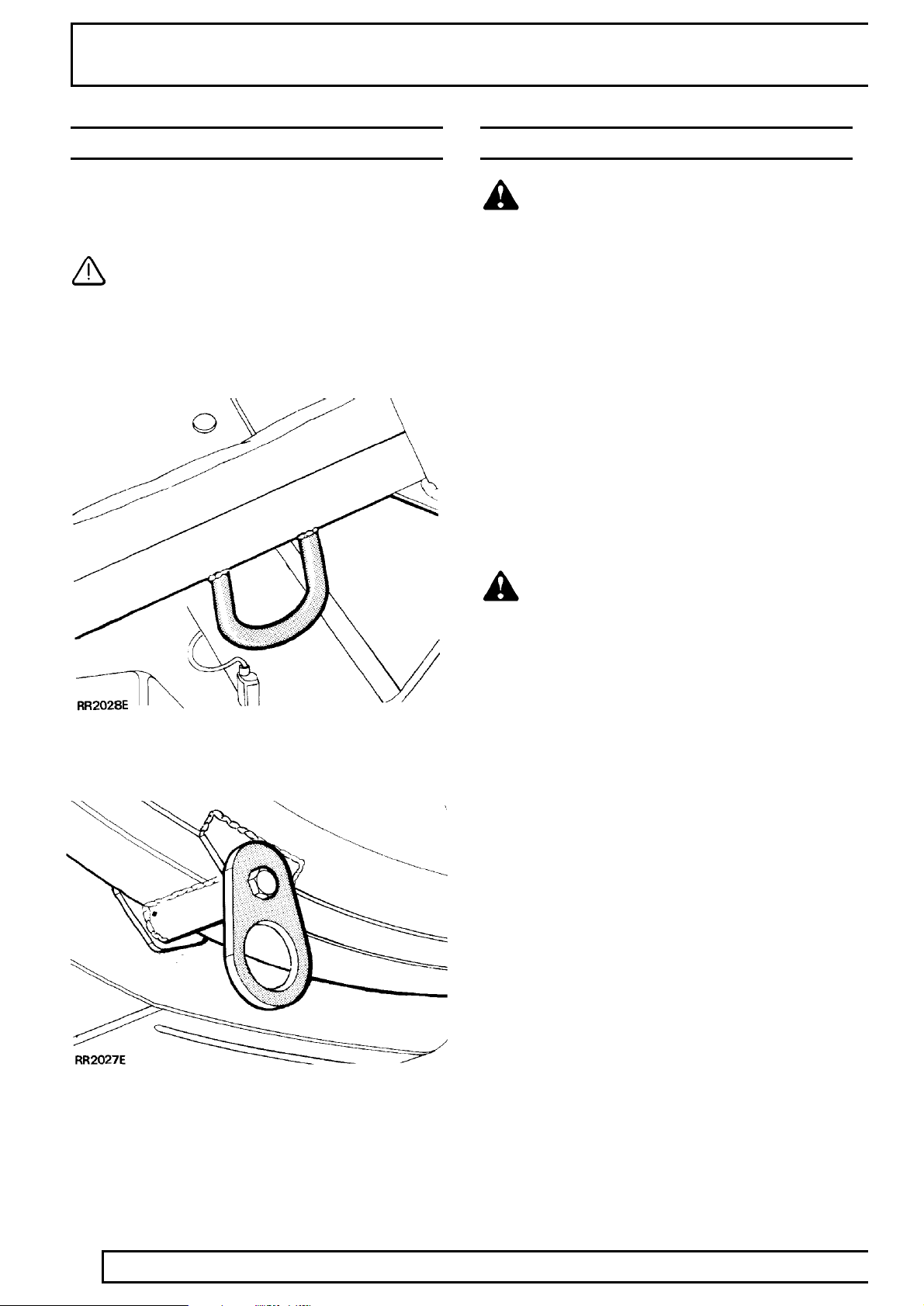
TOWING
CAUTION: The vehicle has permanent
four-wheel drive. The following towing
instructions must be adhered to:
Towing the vehicle on all four wheels with driver
operating steering and brakes.
1. Turn ignition key turn to position ’1’ to release
steering lock.
2. Select neutral in main gearbox and transfer
gearbox.
CAUTION: The brake servo and power
assisted steering system will not be
functional without the engine running.
Greater pedal pressure will be required to apply
the brakes, the steering system will require
greater effort to turn the front road wheels.
The vehicle tow connection should be used only
in normal road conditions, ’snatch’ recovery
should be avoided.
Suspended tow by breakdown vehicle
CAUTION: To prevent vehicle damage,
front or rear propeller shaft MUST BE
removed, dependent upon which axle is
being trailed.
1. Mark propellershaft drive flanges at transfer
gearbox and axles with identification lines to
enable the propeller shaft to be refitted in its
original position.
2. Remove the propeller shaft fixings, remove the
shaft from the vehicle.
3. If the front axle is to be trailed turn ignition key to
position ’1’ to release steering lock.
CAUTION: The steering wheel and/or
linkage must be secured in a straight
ahead position. DO NOT use the steering
lock mechanism for this purpose.
INFORMATION
7
Page 10
01
INTRODUCTION
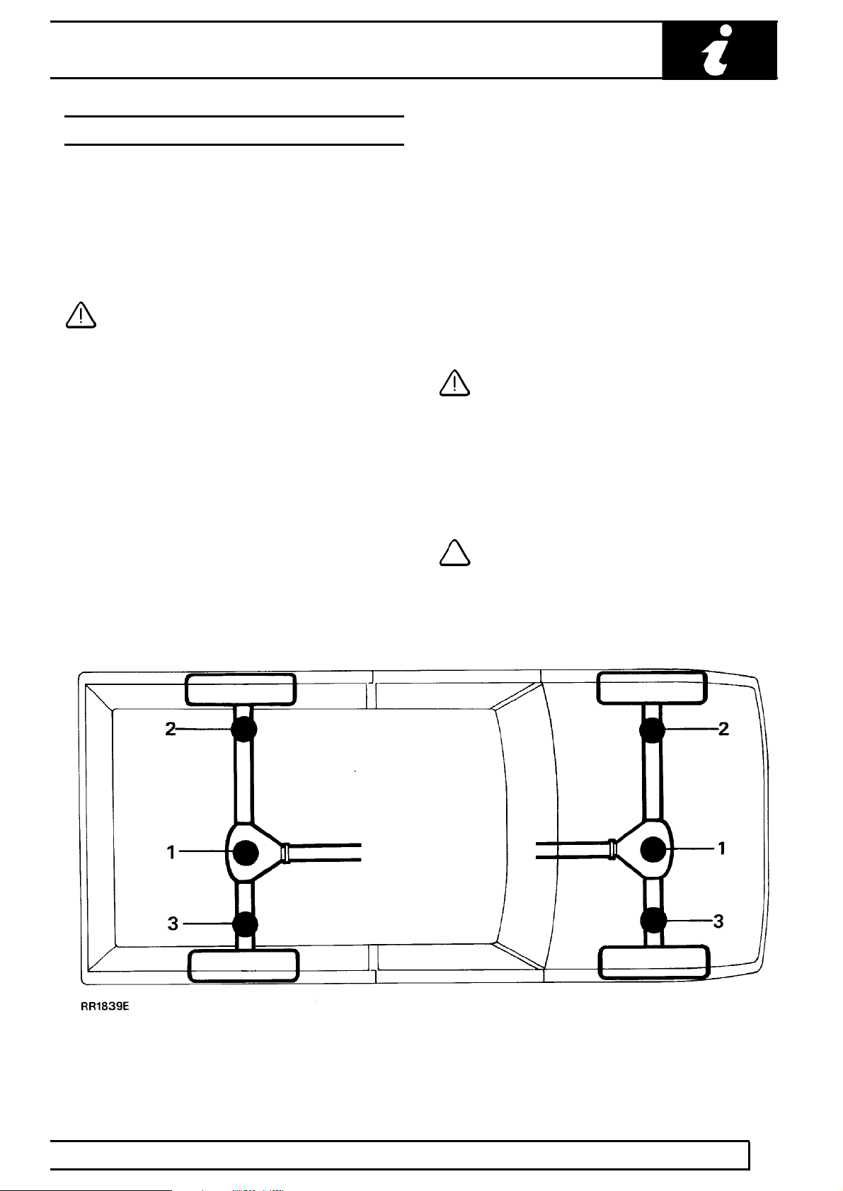
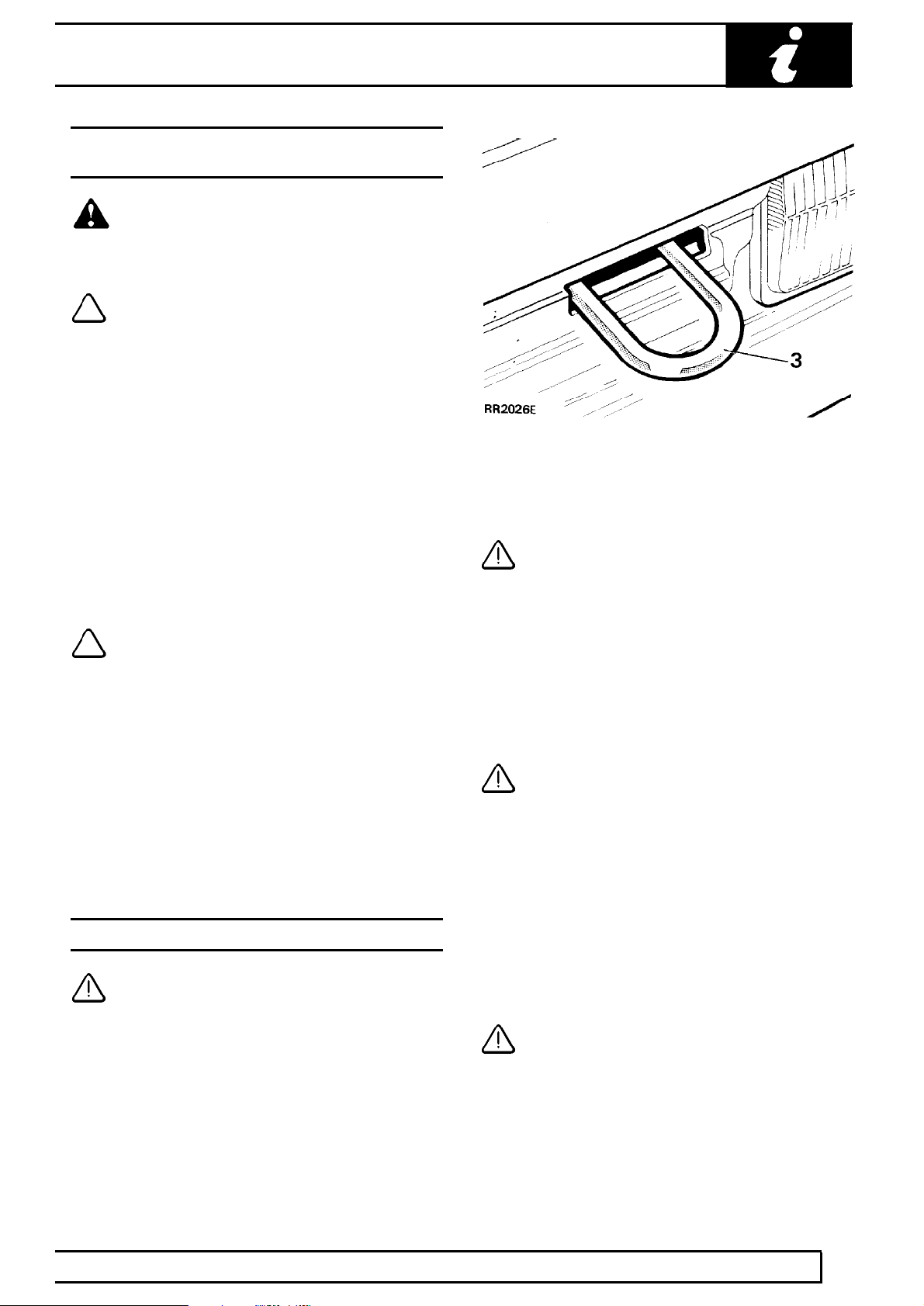
TRANSPORTING THE VEHICLE BY TRAILER
Lashing eyes are provided on front and rear of the
chassis side members, to facilitate the securing of the
vehicle to a trailer or other means of transportation.
CAUTION: Underbody components must
not be used as lashing points.
Install vehicle on trailer and apply park brake. Select
neutral in main gearbox. Selecting ’N’ will prevent
damage to parking pawl of the automatic gearbox.
FRONT OF CHASSIS
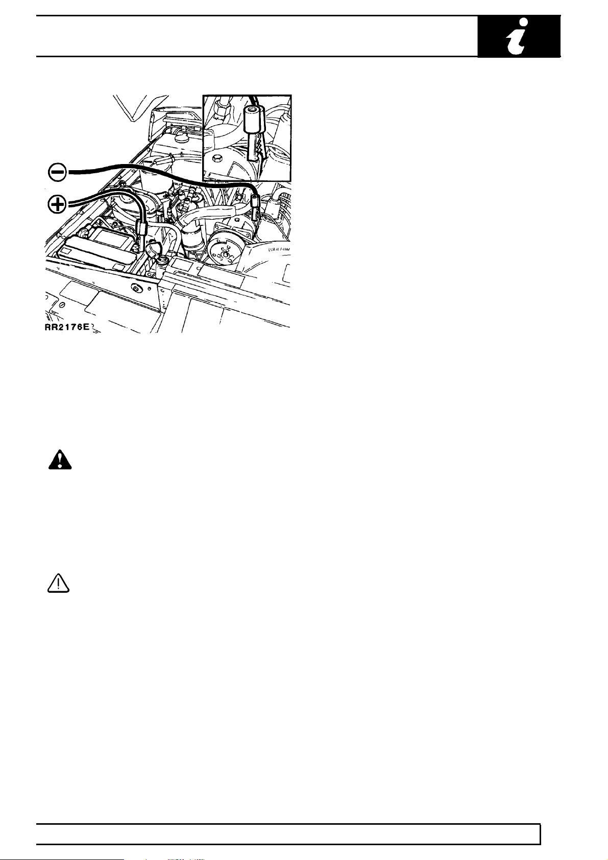
JUMP STARTING
WARNING: Hydrogen and oxygen gases
are produced during normal battery
operation. This gas mixture can explode if
flames, sparks or lighted tobacco are brought
near battery. When charging or using a battery in
an enclosed space, always provide ventilation and
shield your eyes.
Keep out of reach of children. Batteries contain
sulphuric acid. Avoid contact with skin, eyes, or
clothing. Also, shield eyes when working near
battery to protect against possible splashing of
acid solution. In case of acid contact with skin,
eyes, or clothing, flush immediately with water for
a minimum of fifteen minutes. If acid is swallowed,
drink large quantities of milk or water, followed by
milk of magnesia, a beaten egg, or vegetable oil.
SEEK MEDICAL AID IMMEDIATELY.
To Jump Start - Negative Ground Battery
WARNING: To avoid any possibility of
injury use particular care when connecting
a booster battery to a discharged battery.
REAR OF CHASSIS
1. Position vehicles so that jump leads will reach,
ensuring that vehicles DO NOT TOUCH,
alternatively a fully charged slave battery may be
positioned on floor adjacent to vehicle.
2. Ensuring that ignition and all electrical
accessories are switched off, that parking brake
is applied and neutral is selected on a manual
gearbox, with an automatic gearbox select
neutral (N) or park (P) and then connect the
jump leads as follows;
A. Connect one end of first jumper cable to positive
(+) terminal of booster battery.
B. Connect other end of first jumper cable to
positive (+) terminal of discharged battery.
C. Connect one end of second jumper cable to
negative terminal of booster battery.
INFORMATION
8
Page 11
INTRODUCTION
D. Connect other end of second jumper cable to a
good earth point on the engine, NOT TO
NEGATIVE TERMINAL OF DISCHARGED
BATTERY. Keep jumper lead away from moving
parts, pulleys, drive belts and fan blade
assembly.
WARNING: Making final cable connection
could cause an electrical arc which if
made near battery could cause an
explosion.
3. If booster battery is installed in another vehicle,
start engine and allow to idle.
4. Start engine of vehicle with discharged battery,
following starting procedure in Owners’ Manual.
CAUTION: If vehicle fails to start within a
maximum time of 12 seconds, switch
ignition off and investigate cause. Failing
to follow this instruction could result in
irrepairable damage to catalysts.
5. Remove negative (-) jumper cable from the
engine and then terminal of booster battery.
6. Remove positive (+) jumper cable from positive
terminals of booster battery and discharged
battery.
INFORMATION
9
Page 12

01
INTRODUCTION
ABBREVIATIONS AND SYMBOLS USED IN THIS MANUAL
Across flats (bolt size) AF............................................
After bottom dead centre ABDC...................................
After top dead centre ATDC.........................................
Alternating current a.c..................................................
Ampere amp................................................................
Ampere hour amp hr....................................................
Before bottom dead centre BBDC................................
Before top dead centre BTDC......................................
Bottom dead centre BDC.............................................
Brake horse power bhp................................................
British Standards BS....................................................
Carbon monoxide CO..................................................
Centimetre cm.............................................................
Centigrade (Celsius) C................................................
Cubic centimetre cm
Cubic inch in
...................................................
...............................................................
Degree (angle) deg or °...............................................
Degree (temperature) deg or °.....................................
Diameter dia................................................................
Direct current d.c..........................................................
Electronic Control Unit ECU........................................
Electronic Fuel Injection EFI........................................
Fahrenheit F.................................................................
Feet ft...........................................................................
Feet per minute ft/min..................................................
Fifth 5th........................................................................
First 1st........................................................................
Fluid ounce fl oz..........................................................
Foot pounds (torque) lbf ft............................................
Fourth 4th.....................................................................
Gramme (force) gf........................................................
Gramme (mass) g........................................................
Gallons gal...................................................................
Gallons (US) US gal.....................................................
High tension (electrical) H.T.........................................
Internal diameter I.D....................................................
Inches of mercury in. Hg..............................................
Inches in......................................................................
Kilogramme (force) kgf.................................................
Kilogramme (mass.) kg................................................
Kilogramme centimetre (torque) kgf.cm.......................
Kilogramme per square millimetre kgf/mm
Kilogramme per square centimetre kgf/cm
.................
.................
Kilogramme metres (torque) kgf.m..............................
Kilometres km..............................................................
Kilometres per hour km/h.............................................
Kilovolts kV...................................................................
Left-hand LH................................................................
Left-hand steering LHStg.............................................
Left-hand thread LHThd...............................................
Litres litre.....................................................................
Low tension l.t..............................................................
Maximum max.............................................................
Metre m........................................................................
Millilitre ml....................................................................
Millimetre mm...............................................................
Miles per gallon mpg....................................................
Miles per hour mph......................................................
Minute (angle) ’............................................................
Minus (of tolerance) -...................................................
Negative (electrical) -...................................................
Newton metres (torque) Nm........................................
Number No..................................................................
Ohms ohm...................................................................
Ounces (force) ozf.......................................................
3
Ounces (mass) oz........................................................
3
Ounce inch (torque) ozf.in...........................................
Outside diameter O.D..................................................
Part number Part No....................................................
Percentage %...............................................................
Pints pt.........................................................................
Pints (US) US pt...........................................................
Plus (tolerance) +.........................................................
Positive (electrical) +....................................................
Pound (force) lbf..........................................................
Pounds inch (torque) in.lbf...........................................
Pound (mass) lb...........................................................
Pounds per square inch P.S.I......................................
Ratio :...........................................................................
Reference ref...............................................................
Revolution per minute rev/min.....................................
Right-hand RH.............................................................
Second (angle) "...........................................................
Second (numerical order) 2nd......................................
Specific gravity sp.gr....................................................
Square centimetres cm
Square inches in
...............................................
.........................................................
Standard wire gauge s.w.g..........................................
Synchroniser/Synchromesh synchro...........................
Third 3rd.......................................................................
Top dead centre TDC..................................................
United Kingdom UK......................................................
2
Vehicle Identification Number VIN...............................
2
Volts V.........................................................................
Watts W.......................................................................
SCREW THREADS
American Standard Taper Pipe NPTF.........................
British Standard Pipe BSP...........................................
Unified Coarse UNC....................................................
Unified Fine UNF.........................................................
2
2
10
INFORMATION
Page 13

CROSS REFERENCE OF EMISSION SYSTEM TERMINOLOGY
INTRODUCTION
NEW TERM (ACRONYM)
Accelerator pedal (AP).................................................
Air cleaner (ACL)..........................................................
Air conditioning (AC)....................................................
Battery positive voltage (B+)........................................
Closed loop (CL)..........................................................
Closed throttle position (CTP)......................................
Canister purge valve (CANPV)....................................
Data link connector (DLC)...........................................
Diagnostic trouble code (DTC).....................................
Distributor ignition (DI).................................................
Engine control module (ECM)......................................
Engine coolant level (ECL)...........................................
Engine coolant temperature (ECT)..............................
Engine coolant temperature sensor (ECTS)................
Engine speed (RPM)....................................................
Evaporative emission system (EVAP)..........................
Engine fuel temperature sensor (EFTS)......................
4th gear, 3rd gear etc. (4GR, 3GR)..............................
Fuel pump (FP)............................................................
Fan control module (FCM)...........................................
Generator (GEN)..........................................................
Ground (GND)..............................................................
Heated oxygen sensor (H02S)....................................
Idle air control (IAC)......................................................
Idle air control valve (IACV).........................................
Ignition control module (ICM).......................................
Inertia fuel shutoff (IFS)................................................
Inertia fuel shutoff switch (IFSS)..................................
Intake air temperature (IAT).........................................
Malfunction indicator lamp (MIL)..................................
Manifold vacuum zone (MVZ)......................................
Mass air flow sensor (MAFS).......................................
Multiport fuel injection (MFI)........................................
On board diagnostic (OBD)..........................................
Open loop (OL)............................................................
Park/neutral position (PNP).........................................
Park/neutral position switch (PNPS)............................
Programmable read only memory (PROM)..................
Relay module (RM)......................................................
Service reminder indicator (SRI)..................................
Solid state relay module (SSRM).................................
Three way catalytic converter (TWC)..........................
Throttle body (TB)........................................................
Throttle position sensor (TPS)......................................
Torque converter clutch (TCC)....................................
Transmission range (TR)..............................................
Transmission range selector (TRS).............................
Vehicle speed sensor (VSS)........................................
Wide open throttle (WOT)............................................
OLD TERM (ACRONYM)
Throttle pedal (-)..........................................................
Air cleaner (-)...............................................................
Air conditioning (AC)....................................................
Battery plus, bat +, bat feed (B+).................................
Closed loop (-).............................................................
Closed throttle, idle position (-)....................................
Charcoal canister purge valve (-).................................
Serial link (-)................................................................
Fault code (-)...............................................................
Electronic ignition (-)....................................................
Electronic control unit (ECU)........................................
Coolant level (-)...........................................................
Coolant temperature (temp).........................................
Coolant temperature thermistor (-)..............................
Engine speed (rev/min)................................................
Evaporative loss system (ELC)...................................
Fuel temperature thermistor (-)....................................
Fourth gear, 3rd gear (-)..............................................
Fuel pump (-)...............................................................
Condenser fan timer (-)................................................
Alternator (-)................................................................
Ground, earth (B-)........................................................
Lambda (02) sensor (-)................................................
Idle speed control (ISC)................................................
Stepper motor (-).........................................................
Ignition module (-)........................................................
Inertia switch (-)...........................................................
Inertia switch (-)...........................................................
Intake temperature/ambient temperature (-)................
EFI warning lamp (-)....................................................
Manifold depression, vacuum (-).................................
Air flow meter (-)..........................................................
Electronic fuel injection (EFI).......................................
Fault code display unit (-)............................................
Open loop (-)...............................................................
Park or neutral (-).........................................................
Start inhibit switch (-)...................................................
Chip, PROM (PROM)...................................................
Relay (-).......................................................................
Check engine light (-)...................................................
Control unit (-)..............................................................
Catalyst, catalytic converter (CAT)..............................
Throttle housing (-)......................................................
Throttle potentiometer (-).............................................
Direct drive clutch (DDC)..............................................
Transmission gear (-)...................................................
Shift lever, shifter (-)....................................................
Road speed transducer (-)...........................................
Full throttle, wide open throttle (WOT).........................
INFORMATION
11
Page 14
01
INTRODUCTION
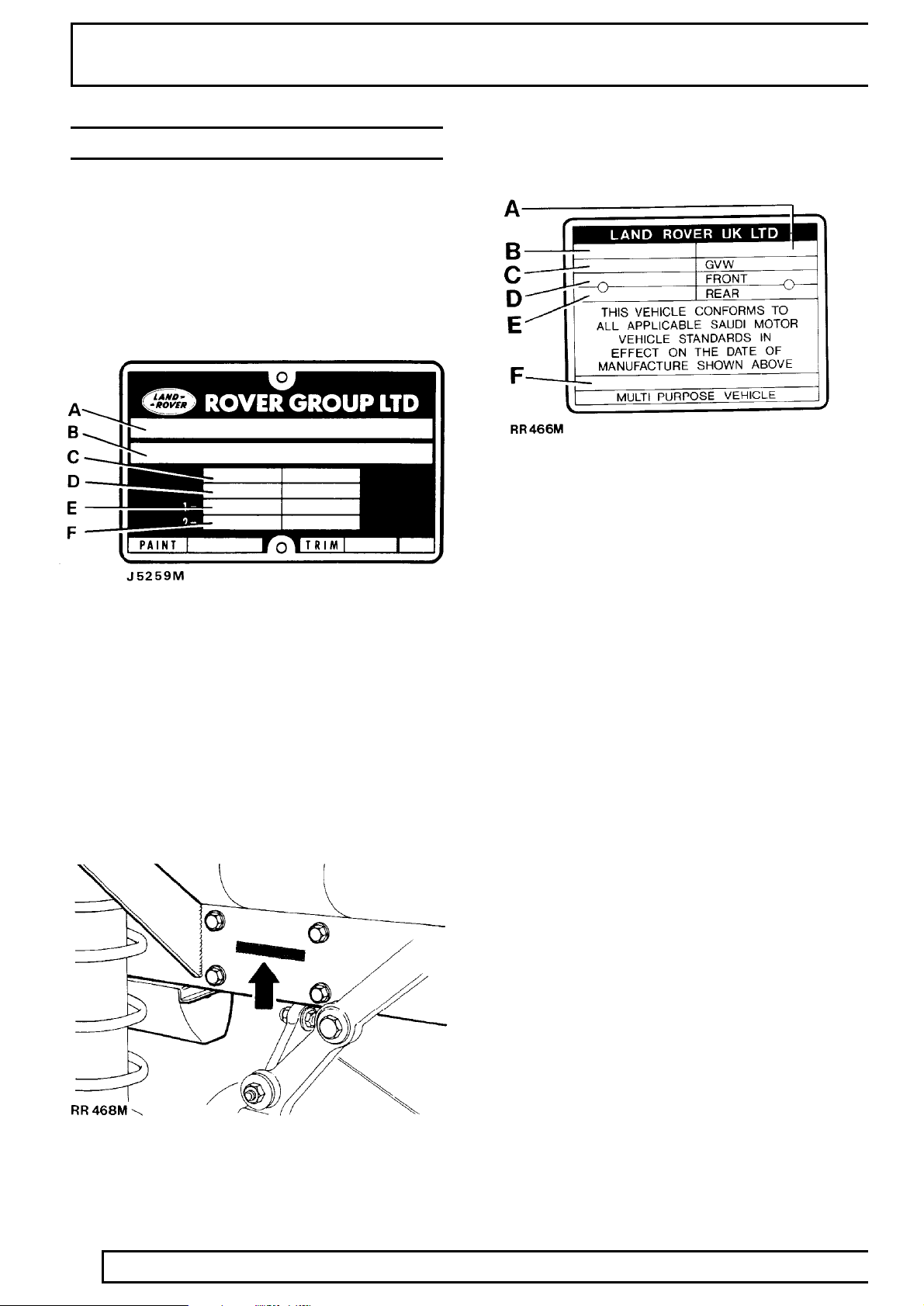
VEHICLE IDENTIFICATION NUMBER (VIN)
The Vehicle Identification Number and the
recommended maximum vehicle weights are stamped
on a plate located under the bonnet [hood] riveted to
the front of the engine compartment.
Vehicle Identification Number Plate (UK, Australia,
R.O.W., Europe)
Vehicle Identification Number Plate (Saudi Arabia)
A. Year of manufacture
B. Month of manufacture
C. Maximum vehicle weight
D. Maximum road weight-front axle
E. Maximum road weight-rear axle
F. VIN (17 digits)
A. Build date (Australia). Type approval
B. VIN (17 digits)
C. Maximum permitted laden weight for vehicle
D. Maximum vehicle and trailer weight
E. Maximum road weight-front axle
F. Maximum road weight-rear axle
The number is also stamped on the right side of the
chassis forward of the spring mounting turret.
The vehicle identification number identifies the
manufacturer, model range, wheel base, body type,
engine, steering, transmission, model year and place
of manufacture. The following example shows the
coding process.
SAL World manufacturer identifier
LH Range Rover or
LJ Discovery
G Class 100 inch
B 2 door
F 300 Tdi or
V V8i Petrol
8 5 speed LHD or
7 5 speed RHD
M 1995 MY
A Solihull site
12
INFORMATION
Page 15
INTRODUCTION
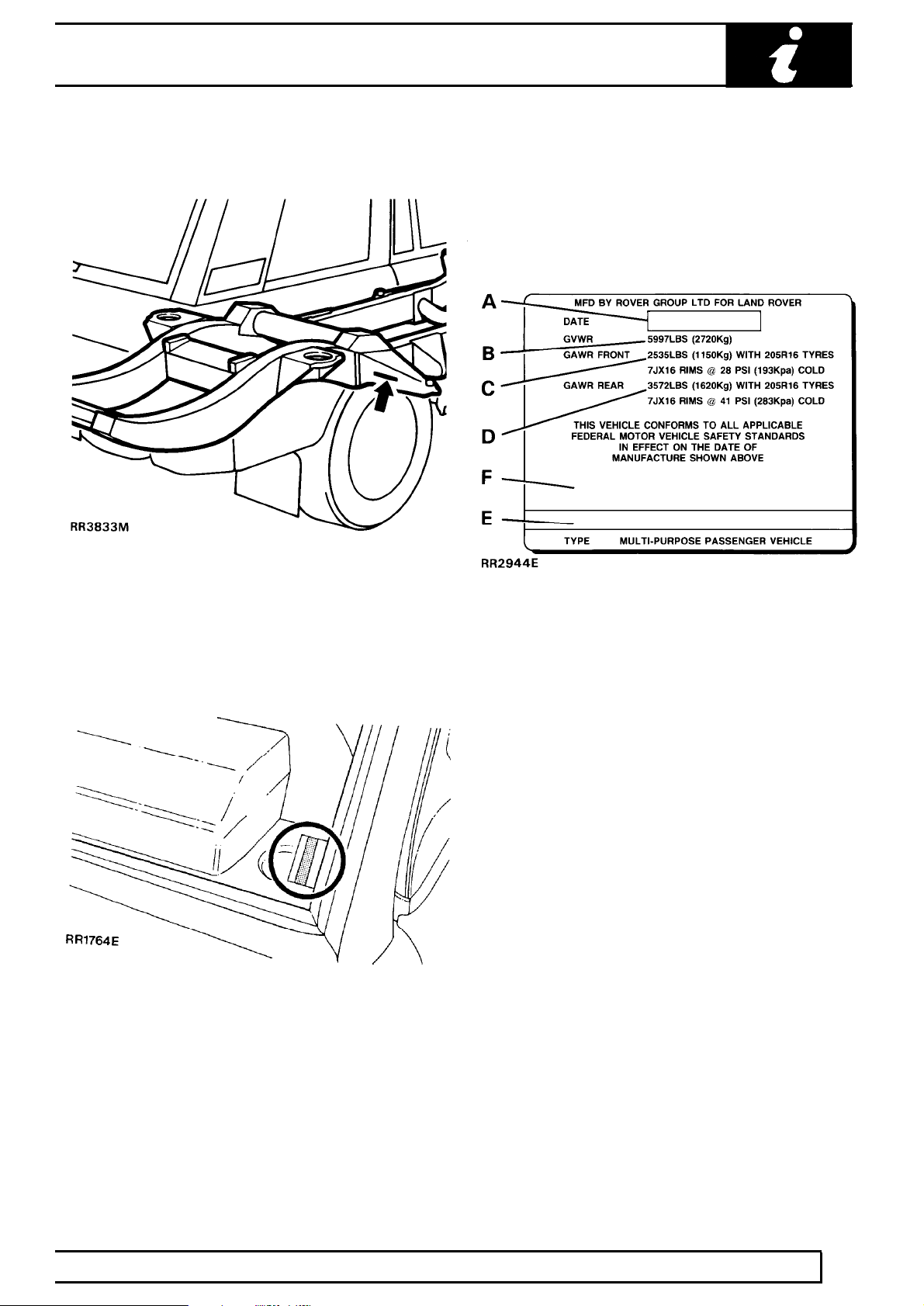
European vehicle identification number (VIN)
Vehicle identification number (VIN)
An adhesive label containing the Vehicle Identification
Number, date of manufacture and gross axle weight
ratings is fixed to the lock face of the front left hand
door. The information includes wheel and tyre sizes
and tyre pressures at gross axle weight ratings.
Stamped on the right hand side chassis forward of
rear wheel.
Federal (USA) vehicle identification number
Stamped on a plate rivetted to the upper left hand ’A’ post, visible through the front screen of the vehicle.
Key to vehicle identification label
A. Month and year of manufacture
B. Gross vehicle weight rating
C. Gross axle weight rating for front axle
D. Gross axle weight rating for rear axle
E. Vehicle identification number (17 digits)
F. Vehicle identification number - bar code
INFORMATION
13
Page 16
01
INTRODUCTION
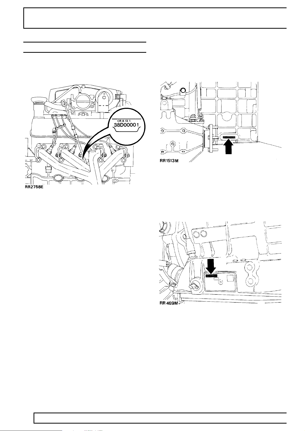
LOCATION OF IDENTIFICATION NUMBERS
Engine serial number - V8i engine
Stamped on a cast pad on the cylinder block, between
numbers 3 and 5 cylinders.
Main gearbox R380
Stamped on a cast pad on the bottom right hand side
of the gearbox.
Automatic gearbox
Engines are identified by the prefix:
3.9 Litre:
35D. - 9.35:1 compression, manual transmission
36D. - 9.35:1 compression, automatic transmission
37D. - 8.13:1 compression, manual transmission
38D. - 8.13:1 compression, automatic transmission
4.2 Litre:
40D. - 8.94:1 compression, automatic transmission
Engine serial number - Diesel engine
Stamped on the RH side of cylinder block above the
camshaft front cover plate.
Stamped on a plate riveted to the bottom left hand
side of the gearbox casing.
14
INFORMATION
Page 17
INTRODUCTION
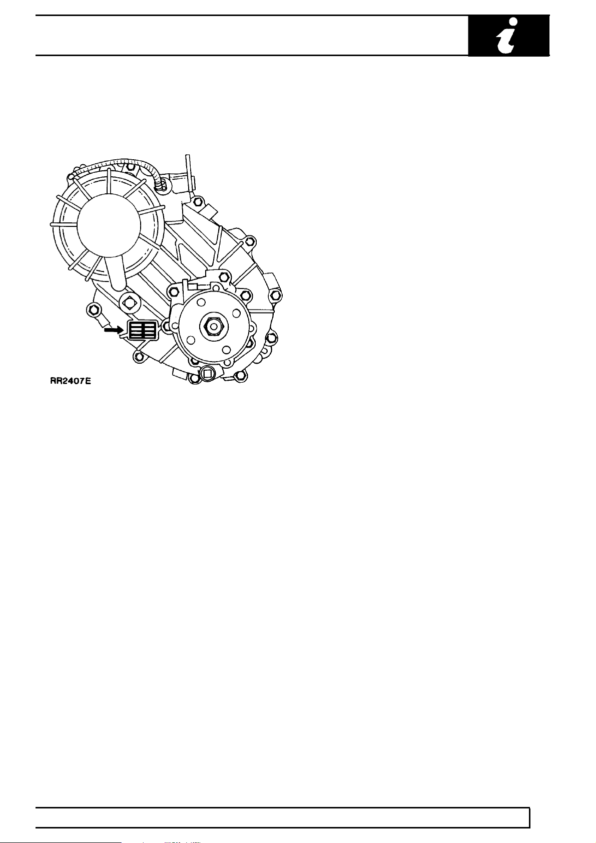
Transfer gearbox-Borg Warner
Stamped on a plate attached to the gearbox casing,
between filler/level and drain plug.
Front and rear axle
Stamped on the top of the left hand axle tubes.
INFORMATION
15
Page 18
01
INTRODUCTION
FAULT DIAGNOSTIC EQUIPMENT
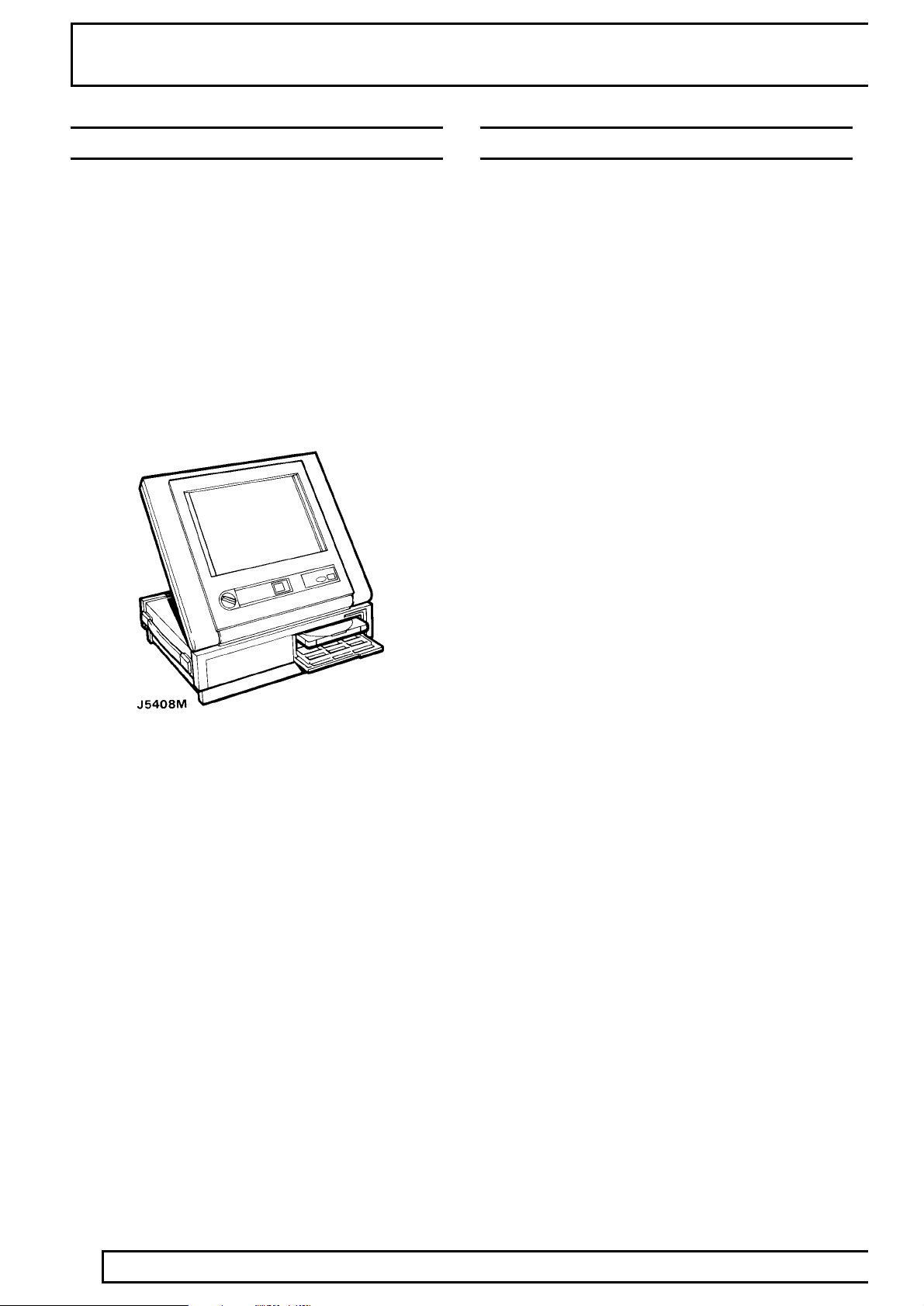
TESTBOOK
Todays Land Rover Vehicles are equipped with a
large amount of electronics to provide the best
performance of the vehicles systems.
Diagnostic equipment named TESTBOOK is available
to expand the diagnostic abilities of the dealer
workshop. This repair manual is produced with
Testbook in mind.
Features of Testbook include: - Fully upgradable
support for the technician. Structured diagnostics to
accommodate all skill levels. Touch screen operation.
Direct print out of screen information and test results.
READING THIS MANUAL
This manual is divided into sections shown on the
contents page, alongside a rang of icons, familiar to
service technicians.
Relevant information is contained within each of these
sections. These are further divided into the following
sub-sections which appear at the foot of each page:
Description and operation.
Fault diagnosis.
Adjustment.
Repair.
Overhaul.
Specifications, Torque.
Service tools.
To avoid repeating information through the sections,
where part of the repair operation impacts on another
section, a cross reference is given to direct the reader
to where the information is sited.
For example:
The maintenance section states the need to renew
V8i drive belt. A cross reference sites this information
in: Section: V8i Engine
- Sub-section: Repairs
- Heading: Drive belt renew
ELECTRICAL TROUBLESHOOTING MANUAL
The Electrical Troubleshooting Manual is a separate
publication that is intended for use by trained Land
Rover technicians as an aid to diagnosing electrical
concerns.
It provides circuit diagrams, system diagnosis flow
charts, electrical component location tables, electrical
component location views, and circuit operation
details.
Sections that contain derivatives such as engines are
further separated into within that section.
American terminology
A few words used in this manual differ to words used
in America. Where this occurs the American word is
placed inside brackets. For example: bonnet [hood],
wing [fender], ramp [hoist].
16
INFORMATION
Page 19

GENERAL SPECIFICATION DATA
ENGINE - V8
Type 3.9 litre V8.................................................................................
Number of cylinders Eight, two banks of four.........................................................
Bore 94.00 mm.................................................................................
Stroke 71.12 mm...............................................................................
Capacity 3950 cm
Valve operation Overhead by push-rod................................................................
Compression ratio 8.13:1 or 9.35:1............................................................
Valve operation Overhead by push-rod................................................................
Maximum power: - 8.13:1 127kW at 4550 rev/min............................
Type 4.2 litre V8.................................................................................
Number of cylinders Eight, two banks of four.........................................................
Bore 94.00 mm.................................................................................
Stroke 77.00 mm...............................................................................
Capacity 4275 cm
Valve operation Overhead by push-rod................................................................
Compression ratio 8.94:1............................................................
Valve operation Overhead by push-rod................................................................
Maximum power 149kWat 4850 rev/min...............................................................
...........................................................................
- 9.35:1 134kW at 4750 rev/min............................
...........................................................................
3
3
Crankshaft
Main journal diameter 58.409-58.422 mm.......................................................
Minimum regrind diameter 57.393-57.406mm...............................................
Crankpin journal diameter 50.800-50.812 mm................................................
Minimum regrind diameter 49.784-49.797mm...............................................
Crankshaft end thrust Taken on thrust washers of centre main bearing.......................................................
Crankshaft end float 0.10-0.20 mm.........................................................
Main bearings
Number and type 5, Vandervell shells..............................................................
Material Lead-indium............................................................................
Diametrical clearance 0.010-0.048 mm.......................................................
Undersize bearing shells 0.254 mm, 0.508 mm..................................................
Connecting rods
Type Horizontally split big-end, plain small-end.................................................................................
Length between centres 143.81-143.71 mm...................................................
Big-end bearings
Type and material Vandervell VP lead-indium............................................................
Diametrical clearance 0.015-0.055 mm.......................................................
End-float crankpin 0.15-0.36mm............................................................
Undersize bearing shells 0.254 mm, 0.508 mm..................................................
Piston pins
Length 72.67-72.79 mm..............................................................................
Diameter 22.215-22.220 mm..........................................................................
Fit-in connecting rod Press fit.........................................................
Clearance in piston 0.002-0.007 mm..........................................................
INFORMATION
1
Page 20

04
Pistons
Clearance in bore, measured at bottom
of skirt at right angles to piston pin 0.018-0.041 mm...................................
Piston rings
Number of compression rings 2..........................................
Number of control rings 1....................................................
No 1 compression ring Molybdenum barrel faced.....................................................
No 2 compression ring Tapered and marked ’T’ or ’TOP’.....................................................
Width of compression rings 1.478-1.49 mm..............................................
Compression ring gap 0.40-0.65 mm......................................................
Oil control ring type Hepworth and Grandage..........................................................
Oil control ring width 3.0 mm.........................................................
Oil control ring rail gap 0.38-1.40 mm.....................................................
Camshaft
Location Central...........................................................................
Bearings Tin-aluminium...........................................................................
Number of bearings 5..........................................................
Drive Chain 9.52 mm pitch x 54 pitches..................................................................................
GENERAL SPECIFICATION DATA
Tappets Hydraulic self-adjusting...........................................................................
Valves
Length: Inlet 116.59-117.35 mm..................................
Exhaust 116.59-117.35 mm...........................
Seat angle: Inlet 45°- 45 1/2°..................................
Exhaust 45°- 45 1/2°...........................
Head diameter: Inlet 39.75-40.00 mm..................................
Exhaust 34.226-34.480 mm...........................
Stem diameter: Inlet 8.664-8.679 mm..................................
Exhaust 8.651-8.666 mm...........................
Stem to guide clearance: Inlet 0.025-0.066 mm..................................
Exhaust 0.038-0.078 mm...........................
Valve lift (Inlet and Exhaust) 9.49 mm............................................
Valve spring length fitted 40.4 mm at pressure of 29.5 kg..................................................
Lubrication
System type Wet sump, pressure fed.....................................................................
Oil pump type Eccentric rotor...................................................................
Oil pressure 2.75 bar (40 lbf/in2) at 2500 rev/min with engine at......................................................................
Oil filter-internal Wire screen, pump intake filter in sump................................................................
Oil filter-external Full flow, self-contained cartridge...............................................................
running temperature
INFORMATION
2
Page 21

GENERAL SPECIFICATION DATA
ENGINE - 300Tdi
Type Direct injection, turbocharged, intercooled.................................................................................
Number of cylinders 4.........................................................
Bore 90,47 mm.................................................................................
Stroke 97,00 mm...............................................................................
Capacity 2495 cm
Compression ratio 19.5:1 ± 0.5:1............................................................
Valve operation O.H.V. pushrod operated................................................................
Turbo charger Garrett T25..................................................................
Crankshaft
Main bearing journal diameter 63,475 - 63,487 mm..........................................
Regrind dimensions 63,2333 - 63,246 mm.........................................................
Crankpin journal diameter 58,725 - 58,744 mm................................................
Regrind dimensions 58,4708 - 58,48985 mm.........................................................
Crankshaft end thrust Taken on thrust washers at centre main bearing.......................................................
Crankshaft end float 0,05 - 0,15 mm.........................................................
...........................................................................
Use 0.010 in U/S bearings
Use 0.010 in U/S bearings
3
Main bearings
Number and type 5 halved shells with oil grooves..............................................................
Diametrical clearance 0,0792 - 0,0307 mm.......................................................
Connecting rods
Length between centres 175,38 - 175,43 mm...................................................
Diametrical clearance (big-end bearings) 0,025 - 0,075 mm........................
End float on crankpin 0,15 - 0,356 mm.......................................................
Pistons
Type Aluminium alloy, combustion chamber in crown.................................................................................
Skirt diametrical clearance
(at right angle to gudgeon pin) 0,025 - 0,05 mm.........................................
Maximum height above combustion face 0,8 mm.........................
Gudgeon pins
Type Floating.................................................................................
Fit in piston Hand push fit.......................................................................
Diameter 30,1564 - 30,1625 mm..........................................................................
Clearance in connecting rod 0,0025 - 0,0163 mm............................................
INFORMATION
3
Page 22

04
Piston rings
Type:
- Top Barrel edge, chrome plated........................................................................
- Second Taper faced..................................................................
- Oil control Expander and rails..............................................................
Gap in bore:
- Top 0,40 - 0,60 mm........................................................................
- Second 0,30 - 0,50 mm..................................................................
- Oil control 0,3 - 0,6 mm..............................................................
Clearance in piston grooves:
- Top 0,167 - 0,232 mm........................................................................
- Second 0,05 - 0,08 mm..................................................................
- Oil control 0,05 - 0,08 mm..............................................................
Camshaft
Drive 30 mm (1.2 in) wide dry toothed belt.................................................................................
Location Right hand side (thrust side)...........................................................................
End float 0,1 - 0,2 mm...........................................................................
Number of bearings 4..........................................................
Material Steel shell, white metal lined............................................................................
GENERAL SPECIFICATION DATA
Valves
Tappet clearance:
- Inlet and exhaust 0,20 mm...................................................
Seat angle:
- Inlet 30°.......................................................................
- Exhaust 45°.................................................................
Head diameter:
- Inlet 39,75 - 39,05 mm.......................................................................
- Exhaust 36,35 - 36,65 mm.................................................................
Stem diameter:
- Inlet 7,960 - 7,975 mm.......................................................................
- Exhaust 7,940 - 7,960 mm.................................................................
Valve lift:
- Inlet 9,67 mm.......................................................................
- Exhaust 9.97 mm.................................................................
Cam lift:
- Inlet 6,81 mm.......................................................................
- Exhaust 7,06 mm.................................................................
Valve head stand down:
- Inlet 0,81 - 1,09 mm.......................................................................
- Exhaust 0,86 - 1,14 mm.................................................................
Valve springs
Type Single coil.................................................................................
Length, free 46,28 mm......................................................................
Length, under 21 kg (46 lb) load 40,30mm......................................
INFORMATION
4
Page 23

GENERAL SPECIFICATION DATA
Lubrication
System Wet sump, pressure fed.............................................................................
Pressure, engine warm at normal operating speeds 1.7-3.8 bar (25 - 55 lbf/in2)........
Oil pump:
- Type Double gear 10 teeth, sintered iron gears......................................................................
- Drive Splinedshaft from camshaft skew gear.....................................................................
- End float of both gears 0,026 - 0,135 mm..........................................
- Radial clearance of gears 0,025 - 0,075 mm.....................................
- Backlash of gears 0,1 - 0,2 mm.................................................
Oil pressure relief valve Non-adjustable....................................................
Relief valve spring:
- Full length 51.6 mm.............................................................
- Compressed length at 7.71 kg load 31.0 mm......................
Oil filter Screw-on disposable canister.............................................................................
Engine oil cooler Combined with coolant radiator and intercooler...............................................................
INFORMATION
5
Page 24

04
FUEL SYSTEM - V8 Engine
Fuel system type Lucas 14CUX hot wire system electronicallycontrolled..............................................................
Fuel pump-make/type High pressure electrical, immersed in the fuel tank......................................................
Fuel pump delivery pressure 2.4-2.6bar(34-37 lbf/in2)............................................
Fuel filter Bosch in-line filter ’canister’ type..........................................................................
Airflow Sensor
Make and type Lucas ’Hot Wire’ 5AM.................................................................
Injectors
Make and type Lucas 8NJ.................................................................
Electronic Control Unit
Make and type Lucas 14CUX.................................................................
Fuel pressure regulator
Make and type Lucas 8RV.................................................................
GENERAL SPECIFICATION DATA
Fuel temperature sensor
Make and type Lucas 6TT.................................................................
Coolant temperature sensor
Make and type Lucas 3TT.................................................................
Bypass Air valve (Stepper motor)
Make and type Lucas 2ACM.................................................................
Throttle potentiometer
Make and type Lucas 215SA.................................................................
Lambda sensor - catalyst vehicles
Make and type Lucas 3LS.................................................................
FUEL SYSTEM - 300Tdi Engine
Injection pump type Bosch rotary VE4/11F.
Injectors
Heater plugs
Fuel lift pump type Mechanical with hand primer............................................................
Fuel lift pump pressure 0.4 - 0.55 bar (6 - lbf/in2) at 1800 rpm.....................................................
Fuel filter Paper element in disposable canister..........................................................................
Air cleaner Paper element type........................................................................
Turbocharger Garrett T25.
...........................................................................
.....................................................................
..........................................................
...................................................................
Information, Engine - 300Tdi
See ENGINE TUNING DATA, Information, Engine
- 300Tdi
See ENGINE TUNING DATA, Information, Engine
- 300Tdi
See ENGINE TUNING DATA,
Information, Engine - 300Tdi
See ENGINE TUNING DATA,
INFORMATION
6
Page 25

GENERAL SPECIFICATION DATA
COOLING SYSTEM - V8 ENGINE
Type Pressurized system with cross- flow radiator and.................................................................................
Type of pump Centrifugal...................................................................
Thermostat 88°C.......................................................................
Expansion tank cap pressure (system pressure) 1.0 bar (15 lbf/in2).............
COOLING SYSTEM - 300Tdi ENGINE
System type Pressurised, spill return, thermostatically controlled.....................................................................
Cooling fan 11 blade axial flow 433 mm diameter. 1.29:1 drive.......................................................................
Pump type Centrifugal, impeller, belt driven.........................................................................
Thermostat opening 88°C.........................................................
Expansion tank cap pressure (system pressure) 1.0 bar (15 lbf/in2).............
remote header tank, thermostat control, pump and fan
assisted
water and anti freeze mixture. Pump assisted thermo
syphon. Coolant radiator combined with oil cooler and
turbo intercooler.
ratio. Viscous coupling.
TRANSMISSION
Clutch
Make and type - V8 engine Borg and Beck, diaphragm spring..............................................
Clutch plate diameter 266.5mm.......................................................
Make and type - Diesel engine Valeo, diaphragm spring.........................................
Clutch plate diameter 235mm.......................................................
Transfer gearbox
Borg Warner Two speed reduction on main gearbox output, front.....................................................................
Transfer gearbox ratios
High 1.206:1..................................................................................
Low 3.244:1..................................................................................
Manual gearbox
Type R380 5 speed, single helical constant mesh with.......................................................................
and rear drive permanently engaged via a centre
differential controlled by a Viscous unit giving a 50/50
nominal front and rear torque split.
synchromesh on all forward gears
INFORMATION
7
Page 26

04
Manual gearbox ratios:
5th 0.731:1...........................................................................
4th 1.000:1...........................................................................
3rd 1.397:1...........................................................................
2nd 2.132:1..........................................................................
1st 3.321:1...........................................................................
Reverse 3.429:1...................................................................
Diesel models low first gear 3.692:1....................................
Overall ratio (final drive): High transfer Low transfer
5th 3.119:1........................................................................... 8.39:1
4th 4.267:1........................................................................... 11.476:1
3rd 5.959:1........................................................................... 16.027:1
2nd 9.095:1.......................................................................... 24.462:1
1st 14.172:1........................................................................... 38.115
Reverse 14.629:1................................................................... 39.346:1
Diesel models low 1st gear 15.750:1..................................... 42.362
Automatic gearbox
Model ZF4HP22...............................................................................
Type Four speed and reverse epicyclic gears with fluid.................................................................................
GENERAL SPECIFICATION DATA
torque converter and lock up.
Automatic gearbox ratios
4th 0.728:1...........................................................................
3rd 1.000:1...........................................................................
2nd 1.480:1..........................................................................
1st 2.480:1...........................................................................
Reverse 2.086:1...................................................................
Overall ratio (final drive): High transfer Low transfer
4th 3.11:1........................................................................... 8.36:1
3rd 4.27:1........................................................................... 11.48:1
2nd 6.32:1.......................................................................... 17.00:1
1st 10.59:1........................................................................... 28.50:1
Reverse 8.91:1................................................................... 23.96:1
INFORMATION
8
Page 27

GENERAL SPECIFICATION DATA
SHIFT SPEED SPECIFICATION - AUTOMATIC ZF4HP22 GEARBOX
OPERATION SELECTOR VEHICLE SPEED ENGINE SPEED
POSITION APPROX APPROX (RPM)
KICKDOWN
MPH KPH
KD4 - 3 D 84 - 92 136 - 150
KD3 - 2 3(D) 57 - 62 91 - 99
KD2 - 1 2(D,3) 27 - 34 44 - 56
KD3 - 4 D N/A N/A
KD2 - 3 D(3) 60 - 63 96 - 104 4750 - 5200
KD1 - 2 D(3,2) 34 - 40 56 - 64 4600 - 5250
FULL THROTTLE
FT4 - 3 D 61 - 67 98 - 108
FT3 - 2 3(D) 40 - 46 64 - 73
FT3 - 4 D 74 - 80 119 - 129 3980 - 4330
FT2 - 3 D(3) 55 - 60 88 - 96 4350 - 4800
T1 - 2 D(3,2) 29 - 34 48 - 56 3950- 465
PART THROTTLE
PT4 - 3 D 47 - 54 75 - 86
PT3 - 2 D(3) 29 - 37 48 - 59
PT2 - 1 D(3,2) 10 - 12 16 - 19
LIGHT THROTTLE
LT3 - 4 D 26 - 30 43 - 49 1430 - 1650
LT2 - 3 D(3) 18 - 22 29 - 35 1420 - 1820
LT1 - 2 D(3,2) 9 - 10 14 - 16 1180 - 1220
ZERO THROTTLE
ZT4 - 3 D 19 - 25 31 - 41
ZT3 - 2 D(3) 12 - 15 19 - 24
ZT2 - 1 D(3,2) 6 - 7 10 - 11
TORQUE CONVERTER
Lock up (IN) D 51 - 54 81 - 86 1875 - 2000
Unlock (OUT) D 49 - 52 78 - 83 1825 - 1930
Note: The speeds given in the above chart are approximate and only intended as a guide. Maximum shift
changes should take place within these tolerance parameters.
INFORMATION
9
Page 28

04
Propeller shafts
Type
Front Tubular 51mm diameter.................................................................................
Front - Catalyst vehicles Solid bar 28.6mm diameter...................................................
Rear Tubular 51mm diameter.................................................................................
Universal joints Open type Hooks O3EHD.................................................................
Rear axle
Type Spiral bevel, fully floating shafts.................................................................................
Ratio 3.54:1.................................................................................
Front axle
Type Spiral bevel, enclosed constant velocity joints,.................................................................................
Ratio 3.54:1.................................................................................
STEERING
GENERAL SPECIFICATION DATA
fully floating shafts
Power steering box
Make/type AdwestVaramatic- worm and roller box........................................................................
Ratio Variable: straight ahead 19.3:1 on lock 17.2:1.................................................................................
Steering wheel turns, lock-to-lock 3.375....................................
Steering pump
Make/type:
V8 engine ZF ’UNICORN’.........................................................................
Diesel engine Hobourn-Eaton series 500...................................................................
Operating pressure - straight ahead position - at idle 7 bar (100 p.s.i.) maximum......
Full lock (left or right) at idle 28 bar (400 p.s.i.) minimum.............................................
Full lock (left or right) 1000 rev/min 70-77 bar (1000-1100 p.s.i.)..................................
Steering geometry
Steering wheel diameter 406.4mm..................................................
Toe-out measurement 0 to 2mm toe out......................................................
Toe-out included angle 0°to 0°16’.....................................................
Camber angle 0°C.................................................................. Check with vehicle in static
unladen condition, that is,
vehicle with water,
Castor angle 3°..................................................................... oil and five gallons of fuel.
Rock the vehicle up and
down at the front to allow
Swivel pin inclination static 7°............................................... it to take up a position
10
INFORMATION
Page 29

GENERAL SPECIFICATION DATA
SUSPENSION
Type:
- Coil spring suspension Coil springs controlled by telescopic dampers front..........................................
- Air suspension Air springs controlled by an ECU providing variable......................................................
Front Lateral location of axle by Panhard rod, and.................................................................................
Rear Lateral location of axle by a centrally positioned ’A’.................................................................................
SHOCK ABSORBERS
and rear.
rate springs and 5 height settings.
longitudinal location by two radius arms.
frame bolted at the apex to a ball joint mounting.
Coil spring suspension: A levelling unit is positioned
between the ball joint and upper cross member.
Longitudinal location of axle by two tubular trailing
links.
Type Telescopic, double-acting non-adjustable.................................................................................
Bore diameter 35.47mm...................................................................
INFORMATION
11
Page 30

04
ROAD SPRING DATA
V8i
LEFT HAND DRIVE Part No. Colour Code
Left hand front NRC4306 Blue/White
Right hand front 572315 Blue
Left hand rear ANR 3519 Brown/Red
Right hand rear ANR 3520 Brown/Yellow
Heavy duty rear NRC 4304 Red/White
RIGHT HAND DRIVE
Left hand front 572315 Blue
Right hand front 572315 Blue
Left hand rear ANR 3520 Brown/Yellow
Right hand rear ANR 3520 Brown/Yellow
Heavy duty rear NRC 4304 Red/White
GENERAL SPECIFICATION DATA
Tdi Diesel
LEFT HAND DRIVE Part No. Colour Code
Left hand front NTC 8476 White/Blue/Pink
Right hand front NRC 8477 Green/Blue/Yellow
Left hand rear ANR 3519 Brown/Red
Right hand rear ANR 3520 Brown/Yellow
Heavy duty rear NRC 4304 Red/White
RIGHT HAND DRIVE
Left hand front NRC 8477 Green/Blue/Yellow
Right hand front NRC 8477
Left hand rear ANR 3520 Brown/Yellow
Right hand rear ANR 3520
Heavy duty rear NRC 4304 Red/White
12
INFORMATION
Page 31

GENERAL SPECIFICATION DATA
BRAKES
Front service brake
Type Outboard discs with four piston calipers.................................................................................
Operation Hydraulic, servo assisted self-adjusting.........................................................................
Pad material Ferodo 3440 non asbestos.....................................................................
Rear service brake
Type Outboard discs with two piston calipers.................................................................................
Operation Hydraulic, servo assisted, self-adjusting.........................................................................
Pad material Ferodo 3440 non asbestos.....................................................................
Parking brake
Type Mechanical-cable operated drum brake on the rear.................................................................................
Lining material Non asbestos..................................................................
Servo/master cylinder
Manufacturer Lucas Girling....................................................................
Servo type LSC 115........................................................................
Master cylinder type AS/AS.........................................................
of the transfer gearbox output shaft
Anti-lock brake system
Manufacturer/type Wabco LRC M15 - 4 channel, 4 wheel sensed............................................................
integrated anti-lock brake system.
INFORMATION
13
Page 32

04
WHEELS AND TYRES
Type and size Alloy 7.00J X 16...................................................................
Tyre size 205R16 (tubeless)..........................................................................
Type and size Steel 6.00JK X 16...................................................................
Tyre size 205R16 (tubed)..........................................................................
AIR CONDITIONING
System CFC free expansion valve system (Nippon Denso).............................................................................
Compressor Nippon Denso 10PA17.....................................................................
GENERAL SPECIFICATION DATA
NOTE: Petrol vehicles must be fitted with ’S’ or ’T’ rated tyres.
Fixed displacement swash plate
WIPER MOTORS
Tailgate wiper motor
Make/type IMOS(non-serviceable)........................................................................
Running current, wet screen at 20°C ambient 1.0 to 2.8 amps.................
Wiper speed, wet screen at 20°C ambient 37 to 43 cycles per minute.......................
Windscreen wiper motor
Make/type Lucas 28W 2-speed........................................................................
Running current (Link disconnected) 1.5 amps at 39 to 45 rev/min (normal speed)...............................
Rotary link speed 60 to 73 rev/min (high speed).............................................................
14
INFORMATION
Page 33

GENERAL SPECIFICATION DATA
ELECTRICAL
System 12 volt, negative ground.............................................................................
Battery
Make/type - basic Land Rover Parts and Equipment/Chloride.............................................................
Make/type - heavy duty Land Rover Parts and Equipment/Chloride....................................................
Generator
Manufacturer Magnetti Marelli....................................................................
Type A133 - 100A.................................................................................
Polarity Negative ground.............................................................................
Brush length
New 20 mm.........................................................................
Worn, minimum free protrusion
from brush box 10 mm........................................................
Brush spring pressure flush with brush box face 136 to 279 g..............
Rectifier pack output rectification 6 diodes (3 positive side and 3 ground side).....................................
Field winding supply rectification 3 diodes......................................
Stator windings 3 phase-delta connected.................................................................
Field winding rotor poles 12..................................................
Maximum speed 16,000 rev/min......................................................
Winding resistance at 20°C 2.6 ohms.....................................
Control Field voltage sensed regulation.............................................................................
Regulator-type 15 TR..................................................................
voltage 13.6 to 14.4 volts....................................................................
Nominal output
Condition Hot.................................................................
Generator speed 6000 rev/min.....................................................
Control voltage 14 volt........................................................
Amp 100 amp.........................................................................
maintenance free 9-plate-210/85/90
maintenance free 14-plate-380/120/90
Fuses
Type Autofuse (blade type).................................................................................
Horns
Make/type Klamix(Mixo)TR99........................................................................
Starter motor
V8 Engine
Make/type Lucas M78R pre-engaged........................................................................
Minimum brush length 3.5 mm.............................................
Minimum commutator diameter 28.8 mm...............................
Diesel Engine
Make and type Bosch 0.001.362.092.................................................................
blow ratings to suit individual circuits
INFORMATION
15
Page 34

04
REPLACEMENT BULBS
Exterior lights
Headlamps 12V 60/55W (Halogen)
Auxiliary driving lamps 12V 55W H3 (Halogen)
Sidelamps 12V 5W bayonet
Tail lamps 12V 5/21W bayonet
Reverse lamps 12V 21W bayonet
Stop lamps 12V 21W bayonet
Direction indicator lamps 12V 21W bayonet
Rear side marker lamps 12V 4W bayonet
Number plate lamps 12V 5W capless
Interior lights
Interior roof lamps 12V 10W ’Festoon’
Door shut face/puddle lamps 12V 5W capless
Instrument panel lamps and warning lamps 14V 1.2W bulb/holder unit
Ignition warning lamp (Instrument panel) 14V 2W capless
SRS warning lamp (Instrument panel) 14V 1.4W capless
Clock illumination 12V 2W bayonet
Cigar lighter illumination 12V 1.2W capless
Auxiliary switch illumination 12V 0.2W capless
Auxiliary switch warning lamp 12V 0.2W capless
Hazard warning switch illumination 14V 0.2W capless
Automatic selector graphics illumination 12V 5W capless
Heater/air conditioning graphics illumination 12V 1.2W capless
GENERAL SPECIFICATION DATA
REPLACEMENT BULBS TYPE
CAUTION: The fitting of new bulbs with wattages in excess of those specified will result in damage
to vehicle wiring and switches.
16
INFORMATION
Page 35

GENERAL SPECIFICATION DATA
VEHICLE WEIGHTS AND PAYLOAD
When loading a vehicle to its maximum (Gross Vehicle Weight), consideration must be taken of the vehicle kerb
weight and the distribution of the payload to ensure that axle loadings do not exceed the permitted maximum
values. It is the customer’s responsibility to limit the vehicle’s payload in an appropriate manner such that neither
maximum axle loads nor Gross Vehicle Weight are exceeded.
Front Rear Total
Basic models Axle kg Axle kg kg
Manual
V8 engine EEC Kerb weight 990 1080 2070
Gross Vehicle Weight* 1100 1510 2510
V8 engine SE EEC Kerb weight 1055 1095 2150
Gross Vehicle Weight* 1100 1510 2510
V8 engine LSE EEC Kerb weight 1090 1095 2185
(long wheelbase models) Gross Vehicle Weight* 1200 1620 2620
Diesel engine
Tdi EEC Kerb weight 1040 1070 2110
Gross Vehicle Weight* 1200 1620 2620
Tdi SE EEC Kerb weight 1105 1085 2110
Gross Vehicle Weight* 1200 1620 2620
NOTE: EEC KERB WEIGHT is the minimum vehicle specification, plus full fuel tank and 75 kg
driver. GROSS VEHICLE WEIGHT is the maximum all-up weight of the vehicle including driver,
passengers, and equipment. This figure is liable to vary according to legal requirements in certain
countries.
Maximum roof rack load (including weight of rack) 75 kg must be included in total vehicle weight.
INFORMATION
17
Page 36

04
VEHICLE DIMENSIONS
Overall length 4.48m...................................................................
- Long wheelbase vehicles 4.68m......................................
Overall width 1.82m....................................................................
Overall height 1.80m...................................................................
Wheelbase 2.54m.......................................................................
- Long wheelbase vehicles 2.74m......................................
Track: front and rear 1.49m.........................................................
Ground clearance: under differential 190mm................................
Turning circle 11.89m....................................................................
- Long wheelbase vehicles 13.64m......................................
Loading height 749mm.................................................................
Maximum cargo height 1.028m.....................................................
Rear opening height 0.87m.........................................................
Usable luggage capacity, rear seat folded 2.00m
Usable luggage capacity, rear seat in use 1.03m
GENERAL SPECIFICATION DATA
.......................
.......................
3
3
TYRE PRESSURES
Pressures: Check Normal on and off-road use. Off-road ’emergency’ soft use
with tyres cold All speeds and loads maximum speed of 40 kph (25 mph)
Front Rear (*) Front Rear
bar 1.9 2.4 (2.6) 1.2 1.8
2
lbf/in
2
kgf/cm
(*) Long wheelbase vehicles (2.74m, 108")
The pressure of tyres must be increased be 0.3 bar (3 lbf in20.2 kgf/cm2). For use with sustained driving speeds
above 160 km/hr (100 miles/hour) or with heavy axle loads.
Normal operating pressures should be restored as soon as reasonable road conditions or hard ground is reached.
After any usage off the road, tyres and wheels should be inspected for damage particularly if high cruising speeds
are subsequently to be used.
Towing: When the vehicle is used for towing, the reduced rear tyre pressures for extra ride comfort are
not applicable.
28 35 (38) 17 25
2.0 2.5 (2.7) 1.2 1.8
18
WARNING: Vehicles fitted with tubeless alloy road wheels as original equipment, note that these
wheels DO NOT accept inner tubes and tubed tyres MUST NOT be fitted.
INFORMATION
Page 37

ENGINE - 3.9 V8
Type 3.9 Litre V8.................................................................................
Firing order 1-8-4-3-6-5-7-2.....................................................................
Cylinder Numbers
Left bank 1-3-5-7..........................................................................
Right bank 2-4-6-8........................................................................
No 1 Cylinder location Pulley end of left bank...................................................
Timing marks On crankshaft vibration damper..................................................................
Spark plugs
Make/type(8.13:1 Compression) Champion RN11YCC......................................
Gap 0.84-0.96mm(0.033-0.038in)..................................................................................
Make/type(9.35:1 Compression) Champion RN11YCC......................................
Gap 0.84-0.96mm(0.033-0.038 in)..................................................................................
ENGINE TUNING DATA
Coil
Make/type Bosch 0-221-122-392, (ETC 6574)........................................................................
Compression ratio 8.13:1 or 9.35:1.........................................................
Fuel injection system Lucas 14 CUX Hot-wire air flow sensor.....................................................
system electronically controlled
Valve Timing Inlet Exhaust
Opens 32°BTDC.............................................................................. 70°BBDC
Closes 73°ABDC.............................................................................. 35°ATDC
Duration 285°........................................................................... 285°
Valve peak 104°ATDC....................................................................... 114°BTDC
Idle speed - controlled by EFi system
- all loads off in neutral 665 to 735 rev/min............................................
- auto gearbox in gear, air con operating 650 ±28 rev/min................
- auto gearbox in gear, air con off 600 ± 28 rev/min...........................
- manual gearbox 700 ± 28 rev/min....................................................
- manual gearbox, air con operating 750 ±28 rev/min.......................
Base idle speed 525 ± 25 rev/min -...............................................................
See FUEL SYSTEM, Fault diagnosis, Base Idle
Speed Setting
Ignition Timing - dynamic at 800 rev/min max, vacuum disconnected
8.13:1 compression, non catalyst 2°BTDC ± 1°.....................................
9.35:1 compression, non catalyst 4°BTDC ± 1°.....................................
9.35:1 compression, catalyst 5°BTDC ± 1°............................................
Exhaust gas
CO content at idle 0.5 to 1.0% max.............................................................
INFORMATION
1
Page 38

05
Distributor
Make/type Lucas 35DLM8 electronic........................................................................
Rotation Clockwise............................................................................
Air gap 0.20-0.35mm..............................................................................
Part number Lucas Rover
8.13:1, non catalyst 42584A................................................. ERR 4753
9.35:1, non catalyst 42552A................................................. ERR 4754
9.35:1, catalyst 42583A........................................................ ERR 4755
Centrifugal Advance
Decelerating check-vacuum hose disconnected
Distributor rpm deceleratingspeeds
8.13:1 non catalyst
2000 Distributor advance........................................................................ 5°30’ to 8°30’
1400 ........................................................................ 6°18’ to 8°30’
800 .......................................................................... 2°to 4°
9.35:1 non catalyst
2200 Distributor advance........................................................................ 7°to 10°
1400 ........................................................................ 7°48’ to 10°
650 .......................................................................... 1°to 3°
ENGINE TUNING DATA
9.35:1 catalyst
2200 Distributor advance........................................................................ 5°30’ to 8°30’
1400 ........................................................................ 6°18’ to 8°30’
800 .......................................................................... 2°to 4°
Fuel
8.13:1, non catalyst 91 RON minimum unleaded.................................................
9.35:1, non catalyst 95 RON minimum unleaded.................................................
9.35:1, catalyst 95 RON minimum unleaded........................................................
USA-Premium unleaded (PUG) CLC or AKI 90 octane minimum..............................
95 RON minimum
Australian market variations
Fuel 91 RON minimum unleaded..................................................................................
Compression ratio 8.13:1............................................................
Spark plug Champion RN11YCC........................................................................
Spark plug gap 0.84-0.96mm (0.033-0.038 in).................................................................
Ignition Timing at 800 rev/min max
(vacuum pipe disconnected) 2°BTDC ± 1°............................................
Exhaust gas idle CO 1% max (hot)........................................................
INFORMATION
2
Page 39

ENGINE - 4.2 V8
Type 4.2 Litre V8.................................................................................
Firing order 1-8-4-3-6-5-7-2.....................................................................
Cylinder Numbers
Left bank 1-3-5-7..........................................................................
Right bank 2-4-6-8........................................................................
No 1 Cylinder location Pulley end of left bank...................................................
Timing marks On crankshaft vibration damper..................................................................
Spark plugs
Make/type Champion RN11YCC........................................................................
Gap 0.84-0.96mm (0.033-0.038 in)..................................................................................
Coil
Make/type Bosch 0-221-122-392, (ETC 6574)........................................................................
ENGINE TUNING DATA
Compression ratio 8.94:1.........................................................
Fuel injection system Lucas 14 CUX Hot-wire air flow sensor system.....................................................
electronically controlled
Valve Timing Inlet Exhaust
Opens 28°BTDC..................................................................... 72°BBDC
Closes 64°ABDC..................................................................... 20°ATDC
Duration 272°.................................................................. 272°
Valve peak 108°ATDC.............................................................. 116°BTDC
Idle speed - controlled by EFi system
- all loads off in neutral 665 to 735 rev/min............................................
-auto gearbox in gear, air con operating 650 ± 28 rev/min.................
-auto gearbox in gear, air con off 600 ± 28 rev/min............................
-manual gearbox 700 ± 28 rev/min.....................................................
-manual gearbox, air con operating 750 ± 28 rev/min........................
Base idle speed 525 ± 25 rev/min -...............................................................
See FUEL SYSTEM, Fault diagnosis, Base Idle
Speed Setting
Ignition Timing
Dynamic, vacuum disconnected 8°BTDC ± 1°at 800 rev/min max.............................
Exhaust gas
CO content at idle 0.5 to 1.0% max.............................................................
INFORMATION
3
Page 40

05
Distributor
Make/type Lucas 35DLM8 electronic........................................................................
Rotation Clockwise............................................................................
Air gap 0.20-0.35mm..............................................................................
Lucas 42510A...............................................................................
Rover Part number ERR 0744...........................................................
Centrifugal Advance
Decelerating check-vacuum hose disconnected
Distributor rpm deceleratingspeeds
2200 7°to 10°........................................................................
1400 7°48’ to 10°........................................................................
800 1°to 3°..........................................................................
Fuel
UK, Europe and Rest of World 95 RON minimum unleaded.........................................
USA - Premium unleaded (PUG) CLC or AKI 90 octane minimum.....................................
ENGINE TUNING DATA
95 RON minimum
INFORMATION
4
Page 41

ENGINE TUNING DATA
ENGINE - 300Tdi
ENGINE
Type 2.5 Litre Turbo diesel with intercooler.................................................................................
Firing order 1-3-4-2.......................................................................
Injection timing 1,54 mm lift at T.D.C..................................................................
- with electronic EGR 1,40 mm lift at T.D.C...............................................
Timing marks:
Valve timing - manual Slot for pin in flywheel and TDC mark on front pulley..............................................
Valve timing - automatic Slot for pin in ring gear, access through rear engine..........................................
plate. TDC mark on front pulley
Injection timing Dial gauge inserted into pump...............................................................
Tappet clearances - inlet and exhaust 0,20 mm cold.............................
Valve timing: Inlet Exhaust
- Opens 16°B.T.D.C.................................................................... 51°BBDC
- Closes 42°ABDC................................................................... 13°ATDC
- Peak 103°ATDC...................................................................... 109°BTDC
- Lift 9,67 mm......................................................................... 9.97 mm
Maximum governed speeds:
- Full load (speed cut-off starts) 4000 rev/min..............................
- No load (flight speed) 4600 + 40 - 120 rev/min............................................
- Idle speed 720 ± 20 rev/min.............................................................
- Die-down time 4 seconds.......................................................
INJECTION PUMP
Make/type:
- Standard Bosch rotary R509 type with boost control and two...............................................................
- with Electronic EGR Bosch rotary R509/1 type with boost control and two..............................................
Direction of rotation Clockwise, viewed from drive end..........................................................
Advance box (two stage) 7°advance with 3°start retard..................................................
Back leakage rate 150-100 Atmospheres:
- New nozzle 7 seconds...........................................................
- Original nozzle 5 seconds......................................................
speed mechanical governor with auto advance and
solenoid electrical shut-off. Tamper proof sealing on
flight speed and fuel adjustment screws. Constant
volume delivery valves.
speed mechanical governor with auto advance and
solenoid electrical shut-off. Tamper proof sealing on
flight speed and fuel adjustment screws. Constant
volume delivery valves. GST start up excess fuel
control. Throttle position sensor for EGR.
INFORMATION
5
Page 42

05
INJECTORS
Make/type
- Standard and Electronic EGR Bosch KBAL 90 P37...............................
Nozzle type DSLA 145P366......................................................................
Opening pressure (working pressure) Initial pressure 200 atmospheres..............................
Secondary 280 atmospheres
- EDC feedback injector 1 in each engine Bosch KBAL 90 P38...............
Nozzle type DSLA 145P365......................................................................
Opening pressure (working pressure) Initial pressure 200 atmospheres..............................
Secondary 300 atmospheres
- EDC standard injector 3 in each engine Bosch KBAL 90 P36...............
Nozzle type DSLA 145P365......................................................................
Opening pressure (working pressure) Initial pressure 200 atmospheres..............................
Secondary 300 atmospheres
GLOW PLUGS
Make/type Probe type, No.0100226129A Beru 12 volts........................................................................
Time to reach operating temperature of 850°C 8 seconds................
ENGINE TUNING DATA
TURBOCHARGER
Make/type Allied signal........................................................................
Maximum boost pressure 0.8-1.0 bar (12-15lbf/in2) measured at wastegate.................................................
actuator ’T’ piece
INFORMATION
6
Page 43

GENERAL FITTING REMINDERS
GENERAL FITTING REMINDERS
WORKSHOP SAFETY IS YOUR RESPONSIBILITY!
The suggestions, cautions and warnings in the
section are intended to serve as reminders for
trained and experienced mechanics. This manual
is not a course in automotive mechanics or
workshop safety.
Shop equipment, shop environment, and the use
and disposal of solvents, fluids, and chemicals
are subject to government regulations which are
intended to provide a level of safety. It is your
responsibility to know and comply with such
regulations.
PRECAUTIONS AGAINST DAMAGE
1. Always fit covers to protect wings before
commencing work in engine compartment.
2. Cover seats and carpets, wear clean overalls
and wash hands or wear gloves before working
inside vehicle.
3. Avoid spilling hydraulic fluid or battery acid on
paint work. Wash off with water immediately if
this occurs. Use Polythene sheets to protect
carpets and seats.
4. Always use a recommended Service Tool, or a
satisfactory equivalent, where specified.
5. Protect temporarily exposed screw threads by
replacing nuts or fitting plastic caps.
SAFETY PRECAUTIONS
1. Whenever possible use a ramp or pit when
working beneath vehicle, in preference to
jacking. Chock wheels as well as applying
parking brake.
WARNING: Do not use a pit when
removing fuel system components.
2. Never rely on a jack alone to support vehicle.
Use axle stands carefully placed at jacking
points to provide rigid support.
3. Ensure that a suitable form of fire extinguisher is
conveniently located.
4. Check that any lifting equipment used has
adequate capacity and is fully serviceable.
5. Disconnect negative (grounded)terminal of
vehicle battery.
WARNING: Do not disconnect any pipes in
air conditioning refrigeration system,
unless trained and instructed to do so. A
refrigerant is used which can cause blindness if
allowed to contact eyes.
6. Ensure that adequate ventilation is provided
when volatile degreasing agents are being used.
7. Do not apply heat in an attempt to free stiff nuts
or fittings; as well as causing damage to
protective coatings, there is a risk of damage to
electronic equipment and brake linings from
stray heat.
INFORMATION
1
Page 44

07
GENERAL FITTING REMINDERS
PREPARATION
1. Before removing a component, clean it and its
surrounding areas as thoroughly as possible.
2. Blank off any openings exposed by component
removal, using greaseproof paper and masking
tape.
3. Immediately seal fuel, oil or hydraulic lines when
separated, using plastic caps or plugs, to
prevent loss of fluid and entry of dirt.
4. Close open ends of oilways, exposed by
component removal, with tapered hardwood
plugs or readily visible plastic plugs.
5. Immediately a component is removed, place it in
a suitable container; use a separate container for
each component and its associated parts.
6. Before dismantling a component, clean it
thoroughly with a recommended cleaning agent;
check that agent is suitable for all materials of
component.
7. Clean bench and provide marking materials,
labels, containers and locking wire before
dismantling a component.
INSPECTION-GENERAL
1. Never inspect a component for wear or
dimensional check unless it is absolutely clean;
a slight smear of grease can conceal an incipient
failure.
2. When a component is to be checked
dimensionally against figures quoted for it, use
correct equipment (surface plates, micrometers,
dial gauges, etc.) in serviceable condition.
Makeshift checking equipment can be
dangerous.
3. Reject a component if its dimensions are outside
limits quoted, or if damage is apparent. A part
may, however, be refitted if its critical dimension
is exactly limit size, and is otherwise satisfactory.
4. Use ’Plastigauge’12 Type PG-1 for checking
bearing surface clearances. Directions for its
use, and a scale giving bearing clearances in
0,0025 mm steps are provided with it.
DISMANTLING
1. Observe scrupulous cleanliness when
dismantling components, particularly when
brake, fuel or hydraulic system parts are being
worked on. A particle of dirt or a cloth fragment
could cause a dangerous malfunction if trapped
in these systems.
2. Blow out all tapped holes, crevices, oilways and
fluid passages with an air line. Ensure that any
O-rings used for sealing are correctly replaced or
renewed, if disturbed.
3. Use marking ink to identify mating parts, to
ensure correct reassembly. If a centre punch or
scriber is used they may initiate cracks or
distortion of components.
4. Wire together mating parts where necessary to
prevent accidental interchange (e.g. roller
bearing components).
5. Wire labels on to all parts which are to be
renewed, and to parts requiring further
inspection before being passed for reassembly;
place these parts in separate containers from
those containing parts for rebuild.
6. Do not discard a part due for renewal until after
comparing it with a new part, to ensure that its
correct replacement has been obtained.
INFORMATION
2
Page 45

GENERAL FITTING REMINDERS
BALL AND ROLLER BEARINGS
CAUTION: Never refit a ball or roller
bearing without first ensuring that it is in a
fully serviceable condition.
1. Remove all traces of lubricant from bearing
under inspection by washing in a suitable
degreaser; maintain absolute cleanliness
throughout operations.
2. Inspect visually for markings of any form on
rolling elements, raceways, outer surface of
outer rings or inner surface of inner rings. Reject
any bearings found to be marked, since any
marking in these areas indicates onset of wear.
3. Holding inner race between finger and thumb of
one hand, spin outer race and check that it
revolves absolutely smoothly. Repeat, holding
outer race and spinning inner race.
4. Rotate outer ring gently with a reciprocating
motion, while holding inner ring; feel for any
check or obstruction to rotation, and reject
bearing if action is not perfectly smooth.
5. Lubricate bearing generously with lubricant
appropriate to installation.
6. Inspect shaft and bearing housing for
discoloration or other marking suggesting that
movement has taken place between bearing and
seatings. (This is particularly to be expected if
related markings were found in operation 2).
7. Ensure that shaft and housing are clean and free
from burrs before fitting bearing.
8. If one bearing assembly of a pair shows an
imperfection it is generally advisable to replace
both with new bearings; an exception could be
made if the faulty bearing had covered a low
mileage, and it could be established that
damage was confined to it only.
9. When fittingbearing to shaft, apply force only to
inner ring of bearing, and only to outer ring when
fitting into housing. (Refer to ST1042M).
10. In the case of grease lubricated bearings (e.g.
hub bearings) fill space between bearing and
outer seal with recommended grade of grease
before fitting seal.
11. Always mark components of separable bearings
(e.g. taper roller bearings) in dismantling, to
ensure correct reassembly. Never fit new rollers
in a used outer ring, always fit a complete new
bearing assembly.
INFORMATION
3
Page 46

07
OIL SEALS
replacement seal.
1. Always fit new oil seals when rebuilding an
assembly.
2. Carefully examine seal before fitting to ensure
that it is clean and undamaged.
3. Coat the sealing lips with clean grease; pack
dust excluder seals with grease, and heavily
grease duplex seals in cavity between sealing
lips.
4. Ensure that seal spring, if provided, is correctly
fitted.
5. Place lip of seal towards fluid to be sealed and
slide into position on shaft, using fitting sleeve
when possible to protect sealing lip from damage
by sharp corners, threads or splines. If fitting
sleeve is not available, use plastic tube or tape
to prevent damage to sealing lip.
GENERAL FITTING REMINDERS
NOTE: Ensure that the seal running track
is free from pits, scores, corrosion and
general damage prior to fitting
7. If correct service tool is not available, use a
suitable drift approximately 0.4mm (0.015 in)
smaller than outside diameter of seal. Use a
hammer VERY GENTLY on drift if a press is not
suitable.
8. Press or drift seal in to depth of housing if
housing is shouldered, or flush with face of
housing where no shoulder is provided. Ensure
that the seal does not enter the housing in a
tilted position.
6. Grease outside diameter of seal, place square to
housing recess and press into position, using
great care and if possible a ’bell piece’ to ensure
that seal is not tilted. (In some cases it may be
preferable to fit seal to housing before fitting to
shaft). Never let weight of unsupported shaft rest
in seal.
NOTE: Most cases of failure or leakage of
oil seals are due to careless fitting, and
resulting damage to both seals and
sealing surfaces. Care in fitting is essential if
good results are to be obtained. NEVER use a seal
which has been improperly stored or handled,
such as hung on a hook or nail.
INFORMATION
4
Page 47

GENERAL FITTING REMINDERS
JOINTS AND JOINT FACES
1. Always use correct gaskets where they are
specified.
2. Use jointing compound only when
recommended. Otherwise fit joints dry.
3. When jointing compound is used, apply in a thin
uniform film to metal surfaces; take great care to
prevent it from entering oilways, pipes or blind
tapped holes.
4. Remove all traces of old jointing materials prior
to reassembly. Do not use a tool which could
damage joint faces.
5. Inspect joint faces for scratches or burrs and
remove with a fine file or oil stone; do not allow
removed material or dirt to enter tapped holes or
enclosed parts.
6. Blow out any pipes, channels or crevices with
compressed air, fit new ’O’ rings or seals
displaced by air blast.
FLEXIBLE HYDRAULIC PIPES, HOSES
1. Before removing any brake or power steering
hose, clean end fittings and area surrounding
them as thoroughly as possible.
2. Obtain appropriate plugs or caps before
detaching hose end fittings, so that ports can be
immediately covered to exclude dirt.
3. Clean hose externally and blow through with
airline. Examine carefully for cracks, separation
of plies, security of end fittings and external
damage. Reject any hose found faulty.
4. When refittinghose, ensure that no unnecessary
bends are introduced, and that hose is not
twisted before or during tightening of union nuts.
5. Containers for hydraulic fluid must be kept
absolutely clean.
6. Do not store brake fluid in an unsealed
container. It will absorb water, and fluid in this
condition would be dangerous to use due to a
lowering of its boiling point.
7. Do not allow brake fluid to be contaminated with
mineral oil, or use a container which has
previously contained mineral oil.
8. Do not re-use brake fluid bled from system.
9. Always use clean brake fluid to clean hydraulic
components.
10. Fit a cap to seal a hydraulic union and a plug to
its socket after removal to prevent ingress of dirt.
11. Absolute cleanliness must be observed with
hydraulic components at all times.
12. After any work on hydraulic systems, inspect
carefully for leaks underneath the vehicle while a
second operator applies maximum pressure to
the brakes (engine running) and operates the
steering.
INFORMATION
5
Page 48

07
GENERAL FITTING REMINDERS
FUEL SYSTEM HOSES
CAUTION: All fuel hoses are made up of
two laminations, an armoured rubber outer
sleeve and an inner viton core. If any of
the fuel system hoses have been disconnected, it
is imperative that the internal bore is inspected to
ensure that the viton lining has not become
separated from the amoured outer sleeve. A new
hose must be fitted if separation is evident.
METRIC NUT IDENTIFICATION
1. A nut with an ISO metric thread is marked on
one face or on one of the flats of the hexagon
with the strength grade symbol 8, 12 or 14.
Some nuts with a strength 4, 5 or 6 are also
marked and some have the metric symbol M on
the flat opposite the strength grade marking.
2. A clock face system is used as an alternative
method of indicating the strength grade. The
external chamfers or a face of the nut is marked
in a position relative to the appropriate hour
mark on a clock face to indicate the strength
grade.
3. A dot is used to locate the 12 o’clock position
and a dash to indicate the strength grade. If the
grade is above 12, two dots identify the 12
o’clock position.
METRIC BOLT IDENTIFICATION
1. An ISO metric bolt or screw, made of steel and
larger than 6 mm in diameter can be identified by
either of the symbols ISO M or M embossed or
indented on top of the head.
2. In addition to marks to identify the manufacture,
the head is also marked with symbols to indicate
the strength grade, e.g. 8.8, 12.9 or 14.9, where
the first figure gives the minimum tensile
strength of the bolt material in tens of kgf/mm2.
3. Zinc plated ISO metric bolts and nuts are
chromate passivated, a gold-bronze colour.
KEYS AND KEYWAYS
1. Remove burrs from edges of keyways with a fine
file and clean thoroughly before attempting to
refit key.
2. Clean and inspect key closely; keys are suitable
for refitting only if indistinguishable from new, as
any indentation may indicate the onset of wear.
TAB WASHERS
1. Fit new washers in all places where they are
used. Always fit a new tab washer.
2. Ensure that the new tab washer is of the same
design as that replaced.
INFORMATION
6
Page 49

GENERAL FITTING REMINDERS
SPLIT PINS
1. Fit new split pins throughout when replacing any
unit.
2. Always fit split pins where cotter pins were
originally used. Do not substitute spring
washers: there is always a good reason for the
use of a split pin.
3. All split pins should be fitted as shown unless
otherwise stated.
SCREW THREADS
1. Both UNF and Metric threads to ISO standards
are used. See below for thread identification.
2. Damaged threads must always be discarded.
Cleaning up threads with a die or tap impairs the
strength and closeness of fit of the threads and
is not recommended.
3. Always ensure that replacement bolts are at
least equal in strength to those replaced.
4. Do not allow oil, grease or jointing compound to
enter blind threaded holes. The hydraulic action
on screwing in the bolt or stud could split the
housing.
5. Always tighten a nut or bolt to the recommended
torque value. Damaged or corroded threads can
affect the torque reading.
6. To check or re-tighten a bolt or screw to a
specified torque value first loosen a quarter of a
turn, then re-tighten to the correct value.
7. Oil thread lightly before tightening to ensure a
free running thread, except in the case of
threads treated with sealant/lubricant, and
self-locking nuts.
NUTS
1. When tighteninga slotted or castellated nut
never loosen it back to insert split pin or locking
wire except in those recommended cases where
this forms part of an adjustment. If difficulty is
experienced, alternative washers or nuts should
be selected, or washer thickness reduced.
2. Where self-locking nuts have been removed it is
advisable to replace them with new ones of the
same type.
NOTE: Where bearing pre-load is involved
nuts should be tightened in accordance
with special instructions.
LOCKING WIRE
1. Fit new locking wire of the correct type for all
assemblies incorporating it.
2. Arrange wire so that its tension tends to tighten
the bolt heads, or nuts, to which it is fitted.
UNIFIED THREAD IDENTIFICATION
1. Bolts
A circular recess is stamped in the upper surface
of the bolt head.
2. Nuts
A continuous line of circles is indented on one of
the flats of the hexagon, parallel to the axis of
the nut.
3. Studs, Brake Rods, etc.
The component is reduced to the core diameter
for a short length at its extremity.
INFORMATION
7
Page 50

LUBRICANTS, FLUIDS AND CAPACITIES
RECOMMENDED LUBRICANTS AND FLUIDS USA VEHICLES
AMBIENT TEMPERATURE ˚C
COMPONENT SPECIFICATION VISCOSITY -30 -20 -10 0 10 20 30 40 50
Engine V8i Use oils to API 5W/20 )
service level
SG or SH 5W/30 )
or 5W/40 )
RES.22.OL.G4
or
CCMC-G4 10W/30
10W/40 )
10W/50 )
15W/40 )
15W/50 )
20W/40 )
20W/50 )
Automatic gearbox ATF Dexron IID
Final drive units API or GL5 90 EP
Swivel pin housings MIL - L - 2105 or
MIL - L - 2105B, C
or D 80W EP
Power steering ATF Dexron IID
Borg Warner ATF Dexron IID
transfer gearbox
Brake reservoir Brake fluid must have a minimum
boiling point of 260˚C (500˚F) and
comply with FMVSS/116/DOT 4
Lubrication nipples
(hubs, ball joints,
etc.)
NLGI-2 multipurpose lithium based
grease
See table on page 3 for remaining vehicle components
INFORMATION
1
Page 51

09
RECOMMENDED LUBRICANTS AND FLUIDS
All climates and conditions
COMPONENT SPECIFICATION VISCOSITY -30 -20 -10 0 10 20 30 40 50
Engine V8i Oils must meet: 5W/30
LUBRICANTS, FLUIDS AND CAPACITIES
AMBIENT TEMPERATURE ˚C
RES.22.OL.G-4 5W/40
or 5W/50
CCMC G-4 or 10W/30
API SG or SH 10W/40
10W/50
15W/40
15W/50
20W/40
20W/50
25W/40
25W/50
Engine TDi RES.22.OL.PD-2 15W/40
or CCMC PD-2
or API CD
Main Gearbox
Automatic
Main Gearbox
manual
Final drive units API or GL5 90 EP
Swivel pin housings MIL - L - 2105 or
Power steering ATF Dexron IID
Borg Warner ATF Dexron IID
Transfer box
ATF Dexron IID
ATF Dexron IID
MIL - L - 2105B 80 EP
CorD
INFORMATION
2
Page 52

LUBRICANTS, FLUIDS AND CAPACITIES
Propeller shaft Front
and Rear
Lubrication nipples
(hubs, ball joints
etc.)
Seat slides
Door lock striker
Brake and clutch
reservoirs
Engine cooling Use an ethylene glycol based anti-freeze (containing no methanol)
system with non-phosphate corrosion inhibitors suitable for use in aluminium engines to ensure
Battery lugs, Petroleum jelly.
Earthing surfaces NOTE: Do not use Silicone Grease
where paint has
been removed
Air Conditioning Refrigerant R134a
System Refrigerant CAUTION: DO NOT use any other type of refrigerant.
Compressor Oil Nippon denso ND-OIL8
NLGI - 2 Multi-purpose Lithium based GREASE
Brake fluids having a minimum boiling point of 260°C (500 °F) and complying with
FMVSS 116 DOT4
the protection of the cooling system against frost and corrosion in all seasons.
UNIPART R134a ND-OIL8
ABS Sensor Silicone grease: Staborags NBU - Wabco 830 502,0634
bush-rear Wacker chemie 704 - Wabco 830 502,0164
Kluber GL301
LUBRICATION PRACTICE
Use a high quality oil of the correct viscosity range and service classification in the engine during maintenance and
when topping up. The use of oil not to the correct specification can lead to high oil and fuel consumption and
ultimately to damaged components.
Oil to the correct specification contains additives which disperse the corrosive acids formed by combustion and
prevent the formation of sludge which can block the oilways. Additional oil additives should not be used. Always
adhere to the recommended servicing intervals.
WARNING: Many liquids and other substances used in motor vehicles are poisonous. They must
not be consumed and must be kept away from open wounds. These substances, among others,
include anti-freeze windscreen washer additives, lubricants and various adhesives.
INFORMATION
3
Page 53

09
CAPACITIES
The following capacity figures are approximate and provided as a guide only. Refer to Section 10 for correct
checking procedure for oil levels.
Capacities (approx.)* Litres Imp Unit US unit
Engine sump and filter from dry
- petrol 6.6..................................................................... 11.60 pints 14.0 pints
- diesel - Tdi 7.0............................................................ 12.30 pints 14.8 pints
Manual gearbox - R380 2.7.................................................... 4.70 pints 5.7 pints
Automatic gearbox 9.1........................................................... 16.00 pints 20 pints
Transfer gearbox from dry 1.7................................................ 3.00 pints 3.6 pints
Front axle from dry 1.7........................................................... 3.00 pints 3.6 pints
Front axle swivel pin housing (each) 0.35................................ 0.60 pints 0.7 pints
Rear axle from dry 1.7............................................................ 3.00 pints 3.6 pints
Power steering box and reservoir 2.9.................................... 5.00 pints 6.0 pints
Cooling system 11.4................................................................ 20.00 pints 24 pints
Fuel tank 89.......................................................................... 19.5 gallons 23 gallons
LUBRICANTS, FLUIDS AND CAPACITIES
NOTE: * All levels must be checked by dipstick or level plugs as applicable.
When draining oil from the ZF automatic gearbox, oil will remain in the torque converter, refill to
high level on dipstick only.
ANTI-FREEZE
ENGINE TYPE MIXTURE STRENGTH PERCENTAGE PROTECTION
CONCENTRATION LOWER
TEMPERATURE
LIMIT
V8 Engine One part anti-freeze
Diesel Engine One part water 50%
Complete protection -33°F
Vehicle may be driven away immediately from cold - 36°C
Safe limit protection -41°C
Coolant in mushy state. Engine may be started and driven away after warm-up
period
-42°F
Lower protection -47°C
Prevents frost damage to cylinder head, block and radiator. Thaw out before
starting engine
CAUTION: Anti-freeze content must never be allowed to fall below 25% otherwise damage to the
engine is liable to occur. Also, anti-freeze content should not exceed 60% as this will greatly
reduce the cooling effect of the coolant.
INFORMATION
4
-53°F
Page 54

LUBRICANTS, FLUIDS AND CAPACITIES
FUEL REQUIREMENTS
Catalyst vehicles
Vehicles equipped with catalytic converter are designed to use ONLY unleaded fuel. Unleaded fuel must be used
for the emission control system to operate properly. Its use will also reduce spark plug fouling, exhaust system
corrosion and engine oil deterioration.
Using fuel that contains lead will result in damage to the emission control system and could result in loss of
warranty coverage. The effectiveness of the catalysts in the catalytic converters will be seriously impaired if leaded
fuel is used. The vehicle is equipped with an electronic fuel injection system, which includes two oxygen sensors.
Leaded fuel will damage the sensors, and will deteriorate the emission control system.
Regulations require that pumps delivering unleaded fuel be labelled UNLEADED. Only these pumps have nozzles
which fit the filler neck of the vehicle fuel tank.
RECOMMENDED FUEL
Petrol engines
- with catalytic converter unleaded only, 95 RON (USA 90 CLC or AKI)..........................................
- non catalytic, 9.35:1 compression ratio leaded 97 RON/unleaded 95 RON.................
- non catalytic, 8.13:1 compression ratio leaded 90 RON/unleaded 95 RON.................
- Australia minimum 91 RON unleaded................................................................
Diesel engines
- 300Tdi Diesel fuel oil, distillate, diesel fuel, automotive gas or...................................................................
Derv to British standard 2869, (1983) class A1 or A2.
Using fuel with an octane rating lower than stated above could seriously impair vehicle performance.
CAUTION: Do not use oxygenated fuels such as blends of methanol/gasoline or ethanol/gasoline
(e.g. ’Gasohol’). Take care not to spill fuel during refuelling.
INFORMATION
5
Page 55

MAINTENANCE
SERVICE SCHEDULE
This section gives information on the range of service
procedures.
Where required, instructions are given for carrying out
each service procedure, or a cross reference is given,
where the procedure can be found in this manual.
Service Schedule sheets are published separately to
reflect the maintenance needs and intervals for each
vehicle variant and model year. Procedures given in
this manual must be used in conjunction with the
service schedule sheets.
The Service Schedule sheets are available in pads
from:
Land Rover Merchandising
PO Box 534
Erdington
Birmingham B24 0QS.
England.
VEHICLE INTERIOR
CHECK SEATS & BELTS
Check condition and security of seats, seat belt
mountings, seat belts, buckles and opertion of inertia
seat belts. Lubricate seat tilt pivots.
CHECK OPERATION OF FOOT BRAKE AND
CLUTCH
If pedal feels ’spongy’ bleed system.
See BRAKES,
Repair, Brake System Bleed (ABS)orSee
BRAKES, Repair, Brake System Bleed (non ABS)
or
See CLUTCH, Repair, Bleed Hydraulic System
Check all hoses and pipes for security, fractures and
leaks. Fit new hoses and pipes as necessary.
CHECK OPERATION OF LAMPS
Check operation of all lamps, horns and warning
indicators.
CHECK OPERATION OF WIPERS
Check operation of front/rear screen wipers and
washers and condition of wiper blades.
CHECK AIR BAG MODULE COVERS
Check visually for signs of damage.
RENEW AIR BAG MODULE
Every ten years
MAINTENANCE
1
Page 56

10
CHECK SECURITY AND OPERATION OF PARK
BRAKE
Parking brake adjust
1. Select a gear or ’P’ in main gearbox.
2. Chock road wheels.
3. Release parkbrake lever.
4. Remove switch panel from centre console.
MAINTENANCE
5. Underneath vehicle, rotate brake adjuster
clockwise until brake shoes are fully expanded
against drum.
6. Back off adjuster until drum is free to rotate.
7. Rotate adjustment thumbwheel below parkbrake
lever until parking brake is fully operational on
third notch of ratchet.
NOTE: Cable adjustment must ONLY be
used for initial setting and to compensate
for cable stretch. It MUST NOT be used to
take up brake shoe wear, which MUST be adjusted
at brake drum.
8. Operate parking brake to settle shoes. Recheck
parkbrake is fully operational on third notch of
ratchet. Readjust if necessary.
9. Refit switch panel.
MAINTENANCE
2
Page 57

MAINTENANCE
VEHICLE EXTERIOR
CHECK/ADJUST HEADLAMP ALIGNMENT
Check/adjust headlamp and auxiliary alignment.
CHECK HEADLAMP LEVELLING SYSTEM
Check system for correct operation.
CHECK FRONT WHEEL ALIGNMENT
Use recognised wheel alignment equipment to
perform this check and adjustment.
See STEERING,
Adjustment, Front Wheel Alignment
INSPECT BRAKE PADS FOR WEAR, CALIPERS
FOR LEAKS AND CONDITION
Check thickness of brake pads, fit new pads if
minimum thickness is less than 3,0mm. Check brake
pads for oil contamination. If new brake pads required.
See BRAKES, Repair, Front Brake Pads
or
See BRAKES, Repair, Rear Brake Pads
WARNING: When renewing brake pads, it
is essential that only genuine components
with correct grade of lining are used.
Always fit new pads as complete axle sets, NEVER
individually or as a single wheel set. Serious
consequences could result from out of balance
braking due to mixing of linings.
Refit road wheels
Fit road wheels in original hub position. Secure in
position with wheel nuts, do not fully tighten wheel
nuts at this stage, lower vehicle and finally tighten
wheel nuts to correct torque.
Alloy wheels:
130 Nm.
REMOVE WHEELS, CHECK TYRES
Check tyres (including spare) for compliance with
manufacturers’ specification.
Check visually for cuts, lumps, bulges, uneven tread
wear and tread depth. Check road wheels for
damage.
Check/adjust tyre pressures.
Steel wheels:
130 Nm.
CHECK SECURITY OF SPARE WHEEL
CHECK OPERATION OF DOORS, BONNET
[HOOD] AND TAILGATE LOCKS
LUBRICATE ALL HINGES, DOOR CHECK
MECHANISMS, BONNET [HOOD] CATCHES AND
FUEL FILLER FLAP
MAINTENANCE
3
Page 58

10
MAINTENANCE
UNDER BONNET [HOOD] MAINTENANCE
CHECK COOLING/HEATER SYSTEMS
Check cooling/heater systems for leaks and hoses for
security and condition.
Cooling system hoses should be changed at first
signs of deterioration.
CHECK BRAKE SERVO HOSE FOR SECURITY
AND CONDITION
CHECK FUEL EVAPORATIVE LOSS CONTROL
SYSTEM FOR LEAKS - V8
CLEAN DISTRIBUTOR CAP - V8
The electronic ignition employs a Lucas 35DLM8
distributor.
Internal operating parts of distributor are pre-set at
factory and do not normally require resetting.
Adjustments should only be made if unit is known to
be faulty or damaged. Distributor maintenance
consists of following items.
1. Clean outer surfaces of distributor cap to remove
dirt, grease etc.
2. Unclip cap, check cap for cracks.
3. Wipe inside cap with lint free cloth.
4. Check rotor arm, cap and flash shield tracking.
DO NOT DISTURB clear plastic insulating
cover (flash shield) which protects magnetic
pick-up module.
LUBRICATE DISTRIBUTOR ROTOR SPINDLE - V8
CHECK FUEL FILLER CAP SEAL FOR LEAKS
CHECK CONDITION OF HEATER PLUG WIRING
FOR FRAYING, CHAFING AND DETERIORATION Tdi
CHECK IGNITION WIRING
Check ignition wiring and high tension leads for
fraying, chafing and deterioration.
Apply a spot of clean engine oil into rotor spindle after
rotor arm has been removed.
CLEAN/ADJUST SPARK PLUGS - V8
RENEW SPARK PLUGS - V8
MAINTENANCE
4
Page 59

Clean, adjust and renew
1. Take great care when fitting spark plugs not to
cross-thread plug, otherwise costly damage to
cylinder head will result.
2. Clean or replace spark plugs as applicable.
3. It is essential that correct type of spark plugs are
fitted.
4. Incorrect grade of plugs may lead to piston
overheating and engine failure.
Remove
MAINTENANCE
5. Disconnect battery negative lead. Remove H.T.
leads from spark plugs.
6. Remove plugs and washers.
Clean spark plugs
7. Fit plug into 14 mm adaptor of approved spark
plug cleaning equipment. Wobble plug in adaptor
with circular motion for three or four seconds
only with abrasive blast in operation. Important:
Excessive abrasive blasting will lead to severe
erosion of insulator nose. Continue to wobble
plug in adaptor with air only, blasting plug for a
minimum of 30 seconds: this will remove
abrasive grit from plug cavity.
8. Wire-brush plug threads; open gap slightly, and
vigorously file electrode sparking surfaces using
a point file. This operation is important to ensure
correct plug operation by squaring electrode
sparking surfaces.
9. Set electrode gap to recommended clearance.
10. Shows dirty plug.
11. Filing plug electrodes.
12. Clean plug, set to correct gap.
13. Test plugs in accordance with plug cleaning
machine manufacturers’ recommendations.
14. Satisfactory plugs can be refitted.
15. When pushing leads onto plugs, ensure that
shrouds are firmly seated.
Fitting H.T. leads
16. Ensure replacement H.T. leads are correctly
refitted as illustrated.
Failure to observe this instruction may result in
cross-firing between two closely fitted leads
which are consecutive in firing order.
MAINTENANCE
5
Page 60

10
CHECK/ADJUST VALVE CLEARANCES. - Tdi
MAINTENANCE
Valve adjustment.
DATA, Information, Engine - 300Tdi
RENEW FUEL FILTER ELEMENT - Tdi
Drain off water and sediment
CAUTION: It is essential that any water
and sediment in fuel filter is drained off, as
water in fuel can result in damage to
injection pump.
1. Hold a small receptacle beneath drain cock.
Unscrew the drain cock half a turn.
2. Drain off water and sediment.
3. Tighten the drain cock immediately fuel starts to
flow from drain cock.
NOTE: Any delay in tightening drain cock
when fuel starts to flow could possibly
mean bleeding fuel system.
See GENERAL SPECIFICATION
Renew fuel filter element
1. Clean area around filter, place a container
beneath.
2. Unscrew filter, a quantity of fuel will be released,
and discard filter.
3. Wet seal of new filter with fuel.
4. Screw new filter into position.
5. Ensure that drain cock is secure.
CHECK POSITIVE CRANKCASE VENTILATION
(PCV) SYSTEM FOR LEAKS AND HOSES FOR
SECURITY AND CONDITION - V8
RENEW AIR CLEANER ELEMENT
- V8 CATALYST - Tdi
- V8 NON CATALYST
To renew air cleaner element
See FUEL SYSTEM, Repair, Air Cleaner
MAINTENANCE
6
Page 61

MAINTENANCE
CLEAN ENGINE BREATHER FILTER - V8
1. Release hose clamp and pull hose off canister.
2. Unscrew canister and remove it from rocker
cover.
3. Remove large ’O’ ring from threaded end of
canister.
4. Visually inspect condition of wire screen within
canister, if in poor condition fit new assembly, if
in acceptable condition clean screen as follows:
5. Immerse canister in small amount of solvent and
allow solvent to dissolve and loosen any debris.
6. Remove canister from solvent and dry in still air.
CLEAN PLENUM CHAMBER VENTILATION
PASSAGEWAY - V8
Cleaning plenum chamber ventilation passageway
can be carried out without removing plenum chamber
from ram housing.
CAUTION: Care must be taken to prevent
debris from passageway passing beyond
throttle butterfly disc.
WARNING: Safety glasses must be worn
when performing this operation. Ensure
that debris is not blown into atmosphere
which could be harmful to other persons closeby.
1. Disconnect battery negative lead.
2. Release hose clamp and remove hose from
plenum chamber inlet.
3. Remove crankcase ventilation hose from side of
plenum chamber.
4. Insert a piece of lint free cloth down throttle
butterfly bore to prevent debris passing throttle
butterfly.
5. Place a cloth over tube protruding from side of
plenum from which ventilation hose was
removed to prevent debris from passageway
being blown into atmosphere.
WARNING: Do not use compressed air line
to remove remaining solvent or debris in
canister, this could cause fire or personal
injury.
Refitting breather/filter
1. Fit new rubber ’O’ ring.
2. Screw canister into rocker cover, hand tight only.
3. Refit hose, tighten clamp securely.
MAINTENANCE
7
Page 62

10
MAINTENANCE
6. Use a compressed air line with a slim bent
nozzle to enable passageway to be cleaned out
from within throttle butterfly bore.
7. Any remaining matter can be dislodged using
soft bent wire or pipe cleaner. Finally blow out
passageway again to remove remaining debris.
8. Remove small ’T’ piece between crankcase
ventilation hoses and check it is free from
blockages, clean as necessary.
9. Refit ’T’ piece and hoses, tighten hose clamps
securely.
RENEW CHARCOAL CANISTER - V8
Charcoal canister
Remove
1. Disconnect battery negative lead.
2. Pry out purge valve.
3. Disconnect pipe.
4. Loosen bolt.
5. Remove charcoal canister.
CHECK CONDITION OF DRIVE BELT - V8 - Tdi
RENEW - V8 - Tdi
Renew V8 drive belt.
Belt - Renew
Renew Tdi drive belt.
Belt - Renew
See ENGINE, Repair, Drive
See ENGINE, Repair, Drive
Refit
6. Reverse removal procedure.
MAINTENANCE
8
Page 63

MAINTENANCE
CHECK THROTTLE AND AUTOMATIC
TRANSMISSION CABLE OPERATION
CHECK/TOP UP AUTOMATIC TRANSMISSION
FLUID LEVEL
NOTE: Transmission fluid level is checked
when fluid is cold with engine idling in
neutral.
1. Ensure vehicle is on level ground.
2. Check fluid level registers between MAX and
MIN marking on dipstick.
CHECK SECURITY OF JACK, BRACE AND
CHOCKS
CHECK/TOP UP COOLING SYSTEM
1. To prevent corrosion of aluminium alloy engine
parts it is imperative that cooling system is filled
with a solution of water and phosphate free
anti-freeze, winter or summer. Never fill or top up
with plain water.
WARNING: Do not remove filler cap when
engine is hot because cooling system is
pressurised and personal scalding could
result.
2. When removing filler cap, turn cap slowly
anti-clockwise, pause and allow all pressure to
escape.
3. Continue to turn until cap is removed.
4. When engine is cold expansion tank coolant
should be level with top of indicator post, visible
inside tank through filler hole.
5. If necessary, top up cooling system with
premixed coolant. Use soft water whenever
possible, if local water supply is hard, rainwater
should be used.
CHECK ENGINE EMISSION CONTROL SYSTEM V8
CHECK OPERATION OF ELECTRONIC CONTROL
UNIT/SYSTEMS - V8
6. When replacing filler cap it is important that it is
tightened down fully. Failure to tighten filler cap
properly may result in water loss, with possible
damage to engine.
The cooling system should be drained and flushed at
2 year intervals or at onset of second winter. Refer to
Coolant Requirements.
See COOLING SYSTEM,
Adjustment, Coolant Requirements
MAINTENANCE
9
Page 64

10
CHECK/TOP UP POWER STEERING FLUID
RESERVOIR
1. Remove fluid reservoir cap. Check that fluid is
up to high mark on dipstick.
CHECK/ TOP UP CLUTCH AND BRAKE FLUID
RESERVOIRS
quantity of water.
MAINTENANCE
CAUTION: Brake fluid can damage
paintwork. If spillage occurs, wash
affected area IMMEDIATELY with a large
CHECK/TOP UP WASHER RESERVOIR
Top up washer reservoir to within 25 mm of filler neck.
Use a screen washer solvent/anti-freeze solution to
assist removing mud, flies and road film and protect
against freezing.
LUBRICATE ACCELERATOR CONTROL
LINKAGES AND PEDAL PIVOT
CHECK/ADJUST IGNITION TIMING - V8
Check ignition timing.
If 3.9.
Information, Engine - 3.9 V8
If 4.2.
Information, Engine - 4.2 V8
See ENGINE TUNING DATA,
See ENGINE TUNING DATA,
10
MAINTENANCE
Page 65

MAINTENANCE
CHECK/ADJUST ENGINE IDLE SPEED - Tdi
For idle speed.
See ENGINE TUNING DATA,
Information, Engine - 300Tdi
CHECK/ADJUST STEERING BOX
Check steering box for fluid leaks.
Check that there is no backlash in steering box in
straight ahead position. Adjust steering box if
necessary.
See STEERING, Adjustment, Power
Steering Box
CLEAN BATTERY CONNECTIONS
Remove battery terminals, clean and coat with
petroleum jelly.
RENEW CAMSHAFT DRIVE BELT - Tdi
Renew camshaft drive belt.
See ENGINE, Repair,
Camshaft Drive Belt and Gears
The engine timing gears are driven by a flexible
rubber belt which must be renewed at intervals
determined by the severity of operating conditions.
In reasonable, temperate climate operation, renew the
belt every 120,000 km (72,000 miles) or every six
years whichever occurs earlier.
In adverse operating conditions such as work in dusty
atmospheres, high ambient temperatures and desert
and tropical zones, renew the belt every 60,000 km
(36,000 miles) or every three years whichever occurs
earlier.
CAUTION: If the drive belt is not renewed
at the correct interval, it could fail,
resulting in serious damage.
A low maintenance battery is installed in vehicle.
Dependent upon climate conditions electrolyte levels
should be checked as follows:
Temperate climates, every three years.
Hot climates, every year.
MAINTENANCE
11
Page 66

10
MAINTENANCE
EXTERNALLY CHECK INTERCOOLER FOR
OBSTRUCTION - Tdi
Clear any trapped dirt or flies from veins of intercooler
CLEAN INTERCOOLER ELEMENT - Tdi
Remove
1. Remove intercooler element.
2. Flush intercoolerwith ICI ’GENKLENE’ or
’D-SOLVE’ propriety cleaner, following the
manufacturer’s instructions.
3. Dry the intercooler completely ensuring that no
liquid remains in the element.
Refit
4. Refit intercooler element.
CHECK TURBO CHARGER BOOST PRESSURE Tdi
For boost pressure.
Information, Turbocharger
1. Disconnect, from turbocharger, hose to actuator.
Insert into a suitable "T" piece.
2. Connect a short length of suitable hose to
turbocharger and connect other end to "T" piece.
3. Connect a further length of hose to third leg of
the "T" piece and other end to a pressure gauge
capable of reading in excess of 61 cm Hg. The
pressure gauge hose must be capable of
reaching passenger compartment so that gauge
may be observed.
4. To check maximum boost pressure, drive
vehicle normally but in such a manner that full
throttle can be maintained whilst climbing a hill
with engine speed held steady between 2,500
and 3,000 rev/min.
See ENGINE TUNING DATA,
12
MAINTENANCE
Page 67

MAINTENANCE
UNDER VEHICLE MAINTENANCE
Vehicles operating under severe conditions of dust,
sand, mud and water should have oils changed and
lubrication carried out at more frequent intervals than
is recommended in maintenance schedules.
RENEW ENGINE OIL AND FILTER - Tdi
CAUTION: Serious damage to the
turbocharger will result is engine is run
above idling speed before oil pressure is
restored.
RENEW ENGINE OIL AND FILTER - V8
CAUTION: To prevent an airlock occuring
after removing filter, fill new filter with oil
and fit immediately after removing old
filter. If airlock does occur fill oil pump with
petroleum jelly.
RENEW AUTOMATIC GEARBOX FLUID AND OIL
SCREEN
1. Place vehicle on either ramp or level ground.
Place suitable container to drain gearbox fluid.
Disconnect battery negative lead.
2. Remove gearbox dipstick, located at rear of right
hand rocker cover, to aid oil drainage. Release
plug from bottom of sump and allow fluid to drain
completely.
3. Refit plug using a new sealing washer. Tighten
to
10 Nm.
CHECK/TOP UP MANUAL GEARBOX OIL - V8
1. Place vehicle on ramp or level ground.
2. Remove oil filler level plug. If necessary, inject
new oil into the gearbox until it runs out of filler
hole. Fit plug. Tighten to
30 Nm.
RENEW MANUAL GEARBOX OIL
Refill ZF Automatic Gearbox and Check Fluid
Level.
NOTE: The fluid level must checked when
fluid is cold and engine idling in park gear.
4. Ensure vehicle is on level ground.
5. Refill or top-up with correct quantity and grade of
fluid.
See LUBRICANTS, FLUIDS AND
CAPACITIES, Information, Recommended
Lubricants and Fluids
MAINTENANCE
13
Page 68

10
MAINTENANCE
6. Reconnect battery negative lead. Start and run
engine, apply footbrake, select Position 1, revert
to park position, release footbrake. Check fluid
level, this must be between two markings on
dipstick.
RENEW TRANSFER GEARBOX OIL
1. Before renewing oil ensure that vehicle is level,
either on a ramp or on ground.
2. Disconnect battery negative lead.
3. Clean immediatearea around filler/level and
drain plugs.
WARNING: When draining gearbox care
should be taken to ensure that oil is not
hot as personal scalding could result.
4. Place a container under gearbox to drain oil into.
5. Remove filler/level plug to vent gearbox and
assist draining.
6. Remove drain plug and allow oil to drain.
Oil screen replacement ZF automatic gearbox.
See AUTOMATIC GEARBOX, Repair, Oil screen
7. Thoroughly clean drain plug threads prior to
applying fresh ’Hylomar’ sealant. Fit plug
Tighten to
8. Fill gearbox with correct quantity and grade of oil
until oil seeps from filler level hole. Wipe away
any surplus oil.
9. Thoroughly clean filler/levelplug threads prior to
applying fresh ’Hylomar’ sealant. Fit plug
Tighten to
10. Reconnect battery negative lead.
25 Nm.
25 Nm.
14
MAINTENANCE
Page 69

MAINTENANCE
CHECK/TOP UP TRANSFER GEARBOX OIL
1. Before topping up oil ensure that vehicle is level,
either on a ramp or on ground.
2. Disconnect battery negative lead.
3. Clean immediatearea around filler/level plug.
4. Remove plug and fill gearbox with recommended
grade of oil, until oil starts to seep from filler/level
hole.
5. Clean any previously applied sealant from
filler/level plug.
6. Apply Hylomar sealant to threads of plug and
refit plug. Tighten to
25 Nm.
RENEW FRONT AND REAR AXLE OIL
1. Vehicle must be level. Place container under
axle to be drained.
2. Using a 13mm square drive wrench, remove
drain and filler/level plugs from axle. Allow oil to
drain completely. Clean and refit drain plug.
3. Inject new oil of recommended make and grade
until it reaches level hole. Clean and refit
filler/level plug and wipe away surplus oil.
7. Wipe away any surplus oil.
8. Reconnect battery negative lead.
CHECK/TOP UP FRONT AND REAR AXLE OIL
1. Vehicle must be level.
2. Using a 13mm square drive wrench, remove
filler/level plug from axle.
3. If necessary inject new oil of recommended
make and grade until it reaches level hole. Clean
and refit filler/level plug and wipe away surplus
oil.
MAINTENANCE
15
Page 70

10
MAINTENANCE
RENEW SWIVEL PIN HOUSING OIL
1. Vehicle must be level. Place container under
swivel to be drained.
2. Remove drain and level plugs, allow oil to drain
completely, clean and refit drain plug.
3. Remove filler plug and inject recommended
make and grade of oil it reaches level hole.
4. Clean and refit level and filler plugs, wipe away
any surplus oil.
LUBRICATE PROPELLER SHAFT SLIDING, AND
UNIVERSAL JOINTS
1. Clean all grease nipples on front and rear
propeller shafts.
2. Using a low pressure hand grease gun, apply
recommended grease, to grease nipples at front
and rear propeller shaft universal and sliding
joints.
NOTE: The rear propeller shaft flexible
coupling is not fitted with a grease nipple.
16
MAINTENANCE
Page 71

MAINTENANCE
LUBRICATE PARKBRAKE MECHANICAL
LINKAGE
CHECK VISUALLY BRAKE, FUEL, CLUTCH
PIPES/UNIONS FOR CHAFING LEAKS AND
CORROSION
CHECK EXHAUST SYSTEM FOR LEAKS,
SECURITY AND DAMAGE
CHECK FOR FLUID LEAKS FROM POWER
STEERING AND SUSPENSION SYSTEMS,
HYDRAULIC PIPES AND UNIONS FOR CHAFING
AND CORROSION
CHECK/TIGHTEN STEERING UNIT AND STEERING
ROD BALL JOINT FIXINGS, CHECK CONDITION
OF OF BALL JOINTS AND DUST COVERS
CHECK TIGHTNESS OF PROPELLER SHAFT
COUPLING BOLTS
Tighten propellor shaft nuts to
47Nm.
ENSURE FRONT AND REAR AXLE BREATHERS
ARE FREE FROM OBSTRUCTION
CHECK/TIGHTEN FRONT AND REAR AXLE
SUSPENSION LINK FIXINGS, CHECK CONDITION
OF MOUNTING RUBBERS
CLEAN FUEL SEDIMENTER - Tdi
Fuel sedimenter
The sedimenter is attached to left-hand side of
chassis frame near fuel tank. It increases the working
life of the fuel filter by removing larger droplets of
water and larger particles of foreign matter from fuel.
Drain off water
Ball joints are lubricated for their normal life during
manufacture and require no further lubrication. This
applies ONLY if rubber boot has not been dislodged
or damaged. Joints should be checked at specified
mileage intervals but more frequently if vehicle is used
under arduous conditions.
1. Check for wear in joints by moving ball joint up
and down vigorously. If free movement is
apparent fit a new joint assembly.
1. Loosen drain plug, allow water to run out.
Tighten plug immediately pure diesel fuel starts
to flow.
MAINTENANCE
17
Page 72

10
MAINTENANCE
Clean element
1. Disconnect fuel inlet pipe from sedimenter and
raise pipe above level of fuel tank. Support in
this position to prevent fuel draining from tank.
2. Support sedimenter bowl, loosen bolt on top of
unit and remove bowl.
3. Remove sedimenter element, clean all parts in
kerosene.
CHECK FOR OIL LEAKS FROM ENGINE AND
TRANSMISSION
DRAIN FLYWHEEL HOUSING IF DRAIN PLUG IS
FITTED FOR WADING
CHECK/TIGHTEN FUEL TANK FIXINGS
4. Fit new seals, reassemble sedimenter.
5. Loosen drain plug, when pure diesel fuel runs
out, tighten plug.
6. Start engine and check sedimenter for leaks.
MAINTENANCE
18
Page 73

RENEW FUEL FILTER - V8
WARNING: Ensure that fuel handling
precautions given in Section 01 -
Introduction regarding fuel handling are
strictly adhered to when carrying out following
instructions.
See INTRODUCTION, Information,
Fuel Handling Precautions
MAINTENANCE
ABS VEHICLES - CHECK ROAD WHEEL SPEED
SENSOR ELECTRICAL HARNESS FOR DAMAGE
WARNING: The spilling of fuel is
unavoidable during this operation. Ensure
that all necessary precautions are taken to
prevent fire and explosion.
1. Depressurise fuel system.
See FUEL SYSTEM,
Repair, Depressurising Fuel system
2. The fuel line filter is located on right hand
chassis side member forward of fuel tank filler
neck. Access to filter is gained through right
hand rear wheel arch.
3. Thoroughly clean area around hose connections
to prevent ingress of foreign matter into fuel
system.
RENEW OXYGEN SENSORS
See EMISSION CONTROL, Repair, Lambda
(Oxygen) Sensor
RENEW CATALYTIC CONVERTERS
See MANIFOLD AND EXHAUST SYSTEM, Repair,
Exhaust System Complete
4. Loosen two fuel unions and remove hoses from
filter canister.
5. Release securing bolt and bracket, remove filter
from chassis side member.
6. Fit a new filter observing direction of flow arrow
on canister.
7. Fit inlet and outlet hoses. Tighten to
8. Refit fuel pump relay.
9. Reconnect battery negative lead.
10. Recode radio.
11. Start engine and inspect hose connections for
fuel leaks.
30 Nm.
MAINTENANCE
19
Page 74

10
MAINTENANCE
CARRY OUT ROAD OR ROLLER TEST
WARNING: The front and rear axles cannot
be driven independently due to the
viscous coupling. Before brake testing a
single axle, reomve the propeller shaft to the rear
axle, AND select neutral in BOTH main gearbox
and transfer gearbox. Run the engine at idle speed
to maintain servo vacuum.
For details of dynamometer testing
INTRODUCTION, Information, Dynamometer
Testing - Non Anti-Lock Brake Vehicles See
INTRODUCTION, Information, Dynamometer
Testing - Vehicles with Anti-Lock Brakes (ABS)
Check following items:
1. Inhibitor switch only operates in P and N.
2. Engine for excessive noise.
3. Clutch for slip, judder or spin.
4. Automatic gear selection/shift speeds.
5. Gear selection/noise - high/low range.
6. Steering for abnormal noise/effort.
7. Steering for free play.
8. All instruments,gauges and warning indicators.
9. Heater and air conditioning systems.
10. Heated rear screen.
11. Shock absorbers - ride irregularities.
12. Foot brake, on emergency stop, pulling to one
side, binding, pedal effort.
13. Parkbrake efficiency.
14. Seat reclining and latching.
15. Fully extend seat belt, check operation of
retraction and latching. Inertia belts lock when
snatched or vehicle on slope.
16. Road wheel balance.
17. Transmission for vibrations.
18. Body noises, squeaks and rattles.
19. Excessive exhaust smoke.
20. Engine idle speed.
21. Endorse service record.
22. Report any unusual features of vehicle condition
and additional work required.
See
RESET EMISSION MAINTENANCE REMINDER USA
The emission maintenance reminder is designed to
activate at 52,500 and 105,000 miles respectively and
will illuminate a ’Service Engine’ red warning light in
instrument binnacle.
The emission maintenance reminder must be reset
after required maintenance has been carried out and
a new tamperproof label fitted by a Land Rover of
North America dealer.
Reset
1. The control unit is located rear of RH front seat.
2. Identify control unit and remove from plug.
3. Remove tamperproof label to reveal access hole
for resetting.
4. Place a thin metallic probe into access hole and
momentarily electrically short between reset pins
inside unit.
20
MAINTENANCE
Page 75

RECOMMENDED SERVICE ITEMS
Refer to Service Schedule sheets for intervals.
Clean sunroof drain tubes, clean and lubricate guide
rails and slides.
MAINTENANCE
Renew the hydraulic brake fluid.
See BRAKES,
Repair, Brake System Bleed
Renew all hydraulic brake fluid, seals, brake servo
filter and flexible hoses.
All working services of the master cylinder and caliper
cylinders should be examined and renewed where
necessary.
ABS vehicles only - renew hydraulic brake fluid and
flexible hoses examine the working surfaces of the
caliper cylinders and renew the seals or cylinders
where necessary.
Air cleaner - When the vehicle is used in dusty or field
conditions or deep wading, frequent attention to the
air cleaner may be required.
ABS vehicles used extensively in arduous off-road
conditions - check the rear wheel road speed sensor
for abrasive wear.
MAINTENANCE
21
Page 76

Tdi
DRIVE BELT INFORMATION
A single ’serpentine drive belt’ drives all the
ancilliaries bar the air conditioning compressor, which
has a separate drive belt. It is essential that the belts
are fitted exactly as shown. It should also be noted
that the water pump/viscous fan is driven in a
clockwise direction.
Off road driving
Regular examination of the drive belt is essential if the
vehicle is used off road. The vehicle driver should be
requested to identify the type of mileage the vehicle
has covered.
After every off road session the owner should inspect
the belt for cuts and possible damage caused by
stones. If belt has jumped, reposition belt correctly. A
new belt must be fitted at the next service or before,
dependant on the type of damage sustained.
Fan cowl
To ensure easy access to the drive belt the top portion
of the fan cowl is detachable.
Check condition
Check condition of drive belt. Renew a belt that shows
signs of wear, splitting or oil contamination.
A drive belt tensioner automatically tensions the drive
belt, eliminating the need for tensioning individual
drive belts. Turning the tensioner pulley in a clockwise
direction will release drive belt tension.
Under normal highway use the belt must be changed
at 160,000 kilometres, 96,000 miles or eight years
whichever occurs first.
The drive belt must be examined at every service and
replaced if necessary.
REPAIR
1
Page 77

12
ENGINE
DRIVE BELT RENEW
Service repair no - 86.10.03
NOTE: If cast lines on tensioner arm and
tensioner spring case are aligned, a new
drive belt must be fitted.
Remove
1. Remove fan cowl upper.
2. Apply ring spanner to tensioner pulley retaining
bolt.
3. Turn spanner to release pulley tension from belt.
4. Detach belt from pulley.
5. Release tensioner.
6. Complete removal of belt. Mark direction on belt
if refitting.
COMPRESSOR DRIVE BELT
Service repair no - 86.10.02
Remove
1. Remove auxiliary drive belt.
Renew
2. Remove compressor shield.
3. Loosen tensioner retaining bolts.
4. Remove compressor drive belt. Mark direction
on belt if refitting.
See Drive Belt
Refit
7. Reverse removal procedure.
Refit
5. Fit compressor drive belt.
6. Fit torque meter to centre of tensioner and apply
and hold a torque of
retaining bolts.
7. Rotate crankshaft 2 full turns.
8. Reapply and hold a torque of
tensioner, then fully loosen and retighten 3
tensioner retaining screws to
35 Nm.
Tighten 3 tensioner
35 Nm
25 Nm.
to
REPAIR
2
Page 78

Tdi
ENGINE
Service repair no - 12.41.01
Remove
CAUTION: Seal all exposed pipe ends
against ingress of dirt after disconnection.
1. Park vehicle on level ground and apply park
brake.
2. Disconnect battery negative lead.
3. Remove bonnet [hood].
See CHASSIS AND
BODY, Repair, Bonnet [Hood]
4. If air conditioning is fitted, remove RH footwell
side trim panel and disconnect harness multiplug
from relay.
6. Remove engine harness grommet from
bulkhead and move harness into engine bay.
7. Release battery positive lead from retaining clip
at base of suspension turret.
8. Remove Radiator Assembly
See COOLING
SYSTEM, Repair, Radiator
9. Discharge air conditioning system.
See AIR
CONDITIONING, Adjustment, Refrigerant
Recovery Recycling Recharging
Remove retaining bolts and disconnect both pipe
adaptors from rear of compressor.
10. Remove rocker cover insulation.
11. Disconnect cyclone hose from air cleaner hose.
12. Remove air cleaner hose from turbocharger.
13. Remove feed pipe/hose from turbocharger and
intercooler.
14. Disconnect heater hoses from cylinder head and
heater rails.
15. Remove bolt securing transmission breather
pipe clip to cylinder head; move breather pipes
aside.
16. Disconnect inlet and outlet hoses from power
steering pump.
17. Disconnect bypass hose from thermostat
housing.
18. Release bypass hose from retaining clips on
front timing cover.
19. Remove split pin securing inner throttle cable to
injector pump.
20. Depress tags on outer cable adjusting nut,
remove cable from mounting bracket, and move
aside.
21. If automatictransmission is fitted, release
kickdown cable from injector pump and mounting
bracket.
5. Disconnect the two engine harness multiplugs
on LH side of footwell.
REPAIR
3
Page 79

12
ENGINE
22. Disconnect feed pipe and spill return pipe from
injector pump.
23. Disconnect both pipes from fuel lift pump.
24. Disconnect servo hose from vacuum pump.
25. Remove three retaining nuts and disconnect
exhaust down pipe.
26. Remove oil cooler pipes from oil filter adaptor.
27. If automatictransmission is fitted, disconnect
feed and return pipes at gearbox oil cooler.
Remove retaining bracket from LH side of
cylinder block and release both oil cooler pipes.
28. Support gearbox.
29. Disconnect ground strap from starter motor.
30. On vehicles with automatic transmission, remove
fixings and detach drive plate housing access
panel and gasket.
31. Working through drive plate housing aperture
mark the torque convertor and drive plate to
facilitate reassembly.
32. Remove the four convertor to flexible drive
securing bolts, rotating crankshaft to gain access
to each individual bolt.
33. Fit engine lifting bracket to the two RH rear
cylinder head fixing bolts.
34. Using suitable hoist, fit lifting chains to engine.
35. Remove four bolts, from both sides, securing
front engine mounting brackets to cylinder block.
36. Remove two bolts, from both sides, securing
front engine mounting bracket to bell housing.
REPAIR
4
Page 80

37. Remove nuts and plain washers securing front
engine mountings to chassis,and lift both engine
mounting bracket assemblies from vehicle.
38. Remove engine to bell housing fixings. Leave
starter motor attached.
39. Raise engine to separate from transmission.
40. Check all connections to engine have been
disconnected.
41. Remove engine.
Tdi
Refit
42. Apply Hylomar to mating faces of bell housing.
Lubricate splines of gearbox primary pinion with
Rocol MV 3.
If automatic transmission, coat the four drive
plate to torque convertor bolts with Loctite 290.
Tighten to
43. Lower engine and locate with transmission.
If manual transmission locate primary pinion into
clutch and engage bell housing dowels. Fit
engine to bell housing fixings. Tighten to
If automatic transmission fixings. Tighten to
Nm.
44. Raise engine, refit front engine mounting
brackets to cylinder block and bell housing.
45. Remove gearbox support and lower engine.
46. Tighten front engine mountings to chassis
fixings. Tighten to
47. Reverse removal procedure. 1 to 37.
39 Nm.
40 Nm.
45 Nm.
46
REPAIR
5
Page 81

12
CRANKSHAFT PULLEY
Service repair no - 12.21.01
ENGINE
Remove
1. Disconnect battery negative lead.
2. Drain coolant.
3. Remove top hose from radiator.
4. Remove intercooler to induction manifold hose.
5. Remove viscous fan and coupling.
COOLING SYSTEM, Repair, Viscous
Coupling, Fan Blades, Pulley and Fan Cowl
6. Remove fan cowl.
7. Remove drive belt.
8. Fit crankshaft pulley retainer LRT-12-080 and
secure with four bolts.
9. Remove crankshaft pulley retaining bolt using
socket and suitable long bar.
See Drive Belt Renew
See
Refit
12. Refit in reverse order, lightly greasing pulley
spigot. Tighten to
80 Nm + 90°.
10. Remove pulley retainer.
11. Remove pulley, if necessary using extractor
LRT-12-049 with thrust pad from LRT-12-031.
REPAIR
6
Page 82

FRONT COVER PLATE
Service repair no - 12.65.01
Tdi
Remove
1. Disconnect battery negative lead.
2. Drain coolant.
3. Remove top hose from radiator.
4. Remove inter-cooler to induction manifold hose.
5. Remove viscous coupling and fan.
See
COOLING SYSTEM, Repair, Viscous
Coupling, Fan Blades, Pulley and Fan Cowl
6. Remove fan cowl.
7. Remove drive belt.
8. Remove crankshaft pulley.
See Drive Belt Renew
See Crankshaft
Pulley
9. Remove 14 bolts securing front cover plate,
noting top two bolts also retain thermostat hose
clips.
10. Remove cover plate complete with gasket.
11. Remove small gasket from centre bolt boss.
Seal replacement
12. Remove worn seal from cover and clean recess.
13. Support cover and fit new seal, open side fitted
into recess, using special tool LRT-12-077.
Refit
14. Refit in reverse order to removal using new
gaskets, fitting the securing bolts as shown in
illustration ST3475. Tighten to
25 Nm.
REPAIR
7
Page 83

12
ENGINE
CAMSHAFT DRIVE BELT AND GEARS
Service repair no - 12.65.18
TIMING BELT
Remove
1. Remove front cover plate.
Plate
2. Position engine at TDC on No. 1 cylinder.
3. If manual gearbox: Remove blanking plug from
flywheel housing and insert timing tool
LRT-12-044. If EDC - timing tool LRT-12-085
must be used.
If automatic gearbox:Sited to the rear of the
engine sump on engine backplate is a blanking
plate. Remove 2 blanking plate bolts and insert
timing tool LRT-12-044 into the larger bolt hole.
See Front Cover
6. Insert pin from special tool LRT-12-045 in
injection pump gear and through into pump
flange.
NOTE: If the camshaft gear is to be
removed during these operations its
retaining bolt should be slackened before
the timing belt is removed.
4. Engage timing tool pin with slot in flywheel.
5. Check correct alignment of timing mark on
camshaft gear and that crankshaft key aligns
with cast arrow on housing.
7. Slacken belt tensioner bolt.
8. Remove idler pulley.
9. Remove timing belt.
NOTE: During use, a belt develops a wear
pattern relative to its running direction, if
the original belt is to be re-used it must be
refitted so that it rotates in the original direction.
CAUTION: Belts must be stored on edge
on a clean surface and in such a manner
that bends are not less than 50 mm radius.
Do not bend belts at an acute angle or radius of
less than 50 mm, otherwise premature failure
could result.
10. Mark belt direction of rotation, using soft chalk,
to ensure correct refitment.
REPAIR
8
Page 84

Belt tensioner
NOTE: The belt tensioner need only be
removed if it is being replaced or for
access purposes to remove front cover.
11. Remove securing bolt and withdraw tensioner
complete with spacer.
Crankshaft gear/front cover oil seal
12. If the crankshaft gear cannot be removed by
hand, use special tool LRT-12-078 with main
body and thrust button from special tool
LRT-12-031 as illustrated ST3478M. Withdraw
gear complete with ’O’ ring seal.
Tdi
13. If necessary prise out oil seal from front cover.
14. Lubricate a new crankshaft oil seal with clean
engine oil.
15. With lip side leading, drive-in seal squarely using
special tool LRT-12-079.
16. Lubricate new ’O’ ring seal with petroleum jelly
and slide onto shaft, taking care not to damage
seal on the woodruff keys.
17. Fit crankshaft gear, tap fully home ensuring ’O’
ring seal is properly seated.
CAMSHAFT GEAR/FRONT COVER OIL SEAL
Service repair no - 12.13.05
18. Remove centre bolt from camshaft gear and
withdraw gear.
19. Remove existing oil seal from front cover using
special tool LRT-12-038.
20. Lubricate a new camshaft oil seal with clean
engine oil.
REPAIR
9
Page 85

12
ENGINE
24. Remove special tool pin from gear.
25. Remove three bolts and withdraw plate and
gear.
21. With lip side leading, drive-in seal squarely using
special tool LRT-12-082.
22. Refit gear.
FUEL INJECTION PUMP GEAR
Service repair no - 19.30.06
Remove
23. Slacken the three bolts on front of gear.
CAUTION: It is important to ensure that
when the injection pump is locked no
attempt must be made to rotate it. Take
care not to allow the crankshaft to be turned.
Refit
26. Fit gear and plate and secure with three bolts.
27. Insert pin from special tool LRT-12-045 in
injection pump gear and through into pump
flange.
10
REPAIR
Page 86

Tdi
Timing belt fitting and tensioning
NOTE: It is important that belt tensioning
is carried out carefully and accurately. The
following procedure involves tensioning
the belt twice to ensure that it is equally tensioned
between each gear. New and original belts are
tensioned to different figures.
28. Ensure timing marks are correctly aligned, pin
from special tool LRT-12-045 is correctly
inserted in injection pump gear and timing tool
LRT-12-044 (LRT-12-085 if EDC) is fitted to
flywheel housing with pin located in flywheel slot.
Or if automatic: Timing tool LRT-12-044 is fitted
to engine backplate and pin located in ring gear.
29. Fit belt observing rotational marks made during
removal. Feed belt over gears keeping it tight on
drive side.
30. Fit idler pulley.
31. Slacken injection pump gear retaining bolts.
32. Adjust belt to correctly sit in gears.
33. Slacken belt tensioner securing bolt to finger
tight.
34. Insert 13 mm square drive extension bar in
tensioner plate.
NOTE: Belt tensioning should be carried
out using a dial type torque meter having a
range not exceeding
meter should be used in the almost vertical
position.
35. Apply a tension of
11 to 13 Nm
is correct tighten clamp bolt.
36. Tighten injection pump gear bolts.
37. Remove pin from injection pump gear.
38. Disengage timing pin from timing slot in flywheel
or ring gear.
39. Rotate crankshaft one and three quarter turns in
a clockwise direction; then continue rotation until
timing pin in timing tool can be engaged with slot
in flywheel or ring gear.
40. Disengage timing pin.
41. Insert pin from special tool LRT-12-045 in
injection pump gear and through into pump
flange.
42. Slacken injection pump gear retaining bolts.
43. Slacken tensioner and retension belt.
44. Tighten injection pump gear retaining bolts.
45. Remove pin from injection pump gear.
46. Remove timing tool and refit plug.
47. Fit front cover plate using new gaskets.
for an original belt. When tension
60 Nm.
14 to 16 Nm
The torque
for a new belt or
See
Front Cover Plate
REPAIR
11
Page 87

12
ENGINE
FRONT COVER/TIMING GEAR HOUSING GASKET
Service repair no - 12.65.10
Remove
1. Remove timing belt and gears.
Drive Belt and Gears
2. Remove fuel injection pump.
SYSTEM, Repair, Fuel Injection Pump and
Timing
3. Remove engine oil sump.
4. Remove oil pick up strainer.
Strainer
5. Remove bolts securing timing gear housing to
block.
6. Withdraw timing gear housing complete with
gasket.
7. Clean all gasket material from mating faces.
See Camshaft
See FUEL
See Oil Sump
See Oil Pick-Up
10. Align flats on oil pump with flats on crankshaft.
11. Fit front cover to block taking care not to damage
oil seal.
12. Secure with bolts of correct length in locations
where slave studs are not fitted (ST3482).
13. Remove slave studs and fit correct length bolts.
14. Tighten to
25 Nm.
Refit
8. Fit slave guide studs to locate gasket.
9. Fit new gasket, over slave studs, to cylinder
block.
15. Fit oil pick-up strainer.
Strainer
16. Fit oil sump.
17. Refit fuel injection pump.
Repair, Fuel Injection Pump and Timing
See Oil Sump
See Oil Pick-Up
See FUEL SYSTEM,
12
REPAIR
Page 88

Tdi
OIL SUMP
Service repair no - 12.60.44
Remove
1. Disconnect battery negative lead.
2. Drain engine oil.
3. Slacken sump securing bolts and, using a sharp
knife, break sealant around sump flange.
4. Remove bolts and withdraw sump.
OIL PICK-UP STRAINER
Service repair no - 12.60.20
Remove
1. Disconnect battery negative lead.
2. Drain engine oil.
3. Remove engine oil sump.
4. Remove bolts securing pipe support bracket.
5. Remove bolts from pipe flanges.
6. Withdraw pick-up strainer assembly.
See Oil Sump
Refit
5. Clean mating faces of sump, timing gear housing
and cylinder block.
6. Apply a 2,0 mm bead of ’Hylosil RTV102’ to the
sump flange, ensuring bead is applied inboard of
the bolt holes.
7. Secure sump to block with bolts. Tighten to
Nm.
8. Refill engine oil.
See LUBRICANTS, FLUIDS
AND CAPACITIES, Information,
Recommended Lubricants and Fluids
9. Reconnect battery negative lead.
25
Refit
7. Refit pick-up strainer assembly, fitting a new ’O’
ring seal at oil pump connection.
8. Apply Loctite 242E to the two screws at the
bearing cap. Tighten to
9. Fit bolts to pipe flanges. Tighten to
10. Refit engine oil sump.
11. Reconnect battery negative lead.
9 Nm.
25 Nm.
See Oil Sump
REPAIR
13
Page 89

12
FLYWHEEL
Service repair no - 12.53.07
ENGINE
Remove
1. Disconnect battery negative lead.
2. Remove gearbox.
Repair, R380 Manual Gearbox
3. Remove clutch.
Assembly
4. Fit two long 8mm bolts into the clutch bolt holes,
diametrically opposite, to use as handles when
lifting the flywheel off the crankshaft.
5. Remove fan cowl
6. Fit crankshaft pulley retainer LRT-12-080 and
secure with four bolts, to restrain crankshaft
while removing flywheel retaining bolts.
7. Remove the bolts and lift off flywheel.
See MANUAL GEARBOX,
See CLUTCH, Repair, Clutch
Refit
8. Locate the flywheel on the crankshaft and
secure with new patched retaining bolts,
progressively tighten to
147 Nm.
NOTE: To prevent excessive flywheel
run-out, ensure that the mating faces of
the flywheel and crankshaft are clean.
9. Check the flywheel for possible run-out by
mounting a dial test indicator with the stylus in a
loaded condition resting on the flywheel face at a
radius of 114mm from the centre.
10. Turn the flywheel and check that run-out does
not exceed 0,05 to 0,07mm. Should run-out be
excessive, remove the flywheel and check again
for irregularities on the crankshaft and flywheel
mating faces and the dowel.
11. Reverse removal procedure. 1 to 6.
14
REPAIR
Page 90

Tdi
CRANKSHAFT REAR OIL SEAL
Service repair no - 12.21.20
Remove
NOTE: The crankshaft rear oil seal is
retained in its own housing, if the seal
requires replacing the housing and seal
assembly (1) must be renewed complete with the
housing seal (3). Housing and seal assemblies are
supplied with their own former/seal guide (2)
already fitted. This former must not be removed
before fitting the assembly to the engine. If a seal
and housing assembly is received without a
former/guide fitted it must be returned to the
supplier. Used formers/guides must be discarded
immediately after use, under no circumstances
should they be reused on other assemblies.
3. Remove clutch.
See CLUTCH, Repair, Clutch
Assembly
4. Remove flywheel.
5. Remove five bolts and withdraw seal housing
and seal assembly complete with gasket.
See Flywheel
1. Disconnect battery negative lead.
2. Remove gearbox.
See MANUAL GEARBOX,
Repair, R380 Manual Gearbox
Refit
6. Insert slave studs to seal housing mounting face.
7. Position new seal housing gasket over slave
studs and crankshaft flange onto cylinder block.
REPAIR
15
Page 91

12
ENGINE
8. Ensure housing seal is correctly seated in its
groove in new housing and seal assembly.
9. Fit new assembly, with former/guide in-situ, over
crankshaft flange, this action will eject
former/guide.
10. Secure assembly to cylinder block with five bolts
tightened to correct torque, removing slave studs
individually and inserting bolts.
11. Refit flywheel.
12. Refit clutch.
Assembly
13. Refit gearbox.
Repair, R380 Manual Gearbox
14. Reconnect battery negative lead.
See Flywheel
See CLUTCH, Repair, Clutch
See MANUAL GEARBOX,
CRANKSHAFT BEARING BUSH
Service repair no - 12.21.45
1. Disconnect battery negative lead.
2. Remove gearbox.
Repair, R380 Manual Gearbox
3. Remove clutch.
Assembly
See MANUAL GEARBOX,
See CLUTCH, Repair, Clutch
4. Remove flywheel.
5. Remove bearing bush.
NOTE: The bearing bush can be removed
by using one of the following methods.
Method 1.
Obtain a short length of steel rod of a diameter having
a good slide fit in the bore of the bush. Pack the bore
with grease and insert the steel rod into the end of the
bore, give a sharp blow with a hammer and the
grease should drive out the bush. It is recommended
that the bush and rod be covered by a suitable cloth
or rag to prevent grease from splashing.
See Flywheel
16
REPAIR
Page 92

Tdi
Method 2.
Thread the bore of the existing bush and using a
suitable bolt extract the bush. Thoroughly clean bush
location ensuring all swarf is removed.
Fitting
6. Fit new bush using a suitable shouldered drift,
inserting bush flush with end of crankshaft.
7. Refit flywheel.
8. Refit clutch.
See Flywheel
See CLUTCH, Repair, Clutch
Assembly
9. Refit gearbox.
See MANUAL GEARBOX,
Repair, R380 Manual Gearbox
10. Reconnect battery negative lead.
FLYWHEEL HOUSING
Service repair no - 12.53.01
Remove
1. Disconnect battery negative lead.
2. Remove gearbox.
See MANUAL GEARBOX,
Repair, R380 Manual Gearbox
3. Remove clutch.
See CLUTCH, Repair, Clutch
Assembly
4. Remove flywheel.
5. Remove starter motor.
6. Remove two bolts from top of flywheel housing.
7. Remove four bolts from bottom of flywheel
housing.
8. Remove six inner bolts and lift off flywheel
housing.
See Flywheel
Refit
9. Clean rear face of housing and mating face on
block, ensuring all old sealant is removed.
REPAIR
17
Page 93

12
ENGINE
10. Apply sealant to flywheel housing mating face on
cylinder block (Fig. J5944).
OIL FILTER
Service repair no - 12.60.01
Remove
1. Place drain tray under filter.
2. Unscrew filter anti-clockwise, using a strap or
spanner.
11. Fit housing to cylinder block and secure with
bolts as removed. Tighten to
12. Remove surplus sealant from block.
13. Refit starter motor.
14. Refit flywheel.
15. Refit clutch.
Assembly
16. Refit gearbox.
Repair, R380 Manual Gearbox
17. Reconnect battery negative lead.
See Flywheel
See CLUTCH, Repair, Clutch
See MANUAL GEARBOX,
45 Nm.
Refit
3. Smear clean engine oil on seal of new filter.
4. Screw on filter until sealing ring touches
machined face, then tighten a further half turn by
hand only. Do not over tighten.
18
REPAIR
Page 94

Tdi
OIL TEMPERATURE CONTROL VALVE
Service repair no - 12.60.69
Remove
1. Disconnect oil cooler pipes.
2. Remove two bolts and carefully withdraw
thermostat extension housing (1) complete with
O ring seal (2), thermostat (3), two washers (4)
and spring (5).
OIL FILTER HEAD GASKET
Service repair no - 12.60.03
Renew
1. Disconnect oil cooler pipes.
2. Disconnect pressure switch lead.
3. Remove securing bolts and withdraw head
complete with gasket.
4. Clean mating faces.
3. Clean adaptor housing.
4. Inspect all parts and renew as necessary.
Refit
5. Fit thermostatto extension housing ensuring pin
locates in hole.
6. Fit two washers and spring to thermostat.
7. Fit a new ’O’ ring to extension housing.
8. Insert spring into adaptor and secure extension
housing to adaptor with bolts. Tighten to
9 Nm.
5. Refit head with new gasket.
6. Secure with bolts Tighten to
7. Refit pipes and reconnect pressure switch.
45 Nm.
REPAIR
19
Page 95

12
ENGINE
CYLINDER HEAD GASKET
Service repair no - 12.29.02
Remove
1. Disconnect battery negative lead.
2. Remove bonnet [Hood].
BODY, Repair, Bonnet [Hood]
3. Drain coolant.
4. Remove air cleaner assembly.
SYSTEM, Repair, Air Cleaner
5. Detach crankcase ventilation valve and side
breather hose from rocker cover and move to
one side.
6. Remove injection pipes.
7. Disconnect spill rail from fuel injectors.
8. Remove fuel injectors and sealing washers.
Identify each injector to the location from which it
is removed.
Injectors
9. Remove inter-connecting harness from glow
plugs.
10. Remove glow plugs.
Repair, Glow Plugs
See FUEL SYSTEM, Repair,
See CHASSIS AND
See FUEL
See FUEL SYSTEM,
11. Remove top hose, radiator to thermostat.
12. Disconnect by-pass hose from thermostat.
13. Disconnect hose, thermostatto water pump.
14. Disconnect water temperature sensor lead.
15. Remove hose inter-cooler to induction manifold.
16. Remove induction manifold.
AND EXHAUST SYSTEM, Repair, Exhaust
Manifold - Tdi
17. Remove exhaust manifold and turbocharger
assembly.
SYSTEM, Repair, Exhaust Manifold - Tdi
18. Disconnect heater hose from water pump and
move heater rail aside.
19. Disconnect heater hose from rear of cylinder
head.
20. Remove bolt securing air cleaner mounting
bracket to support strut.
21. Remove bolt securing harness bracket to
cylinder head.
22. Remove rear lifting bracket, this will also release
clips securing transmission and engine breather
pipes and multiplug. Note loose spacer under
clip securing engine breather pipe and multiplug.
See MANIFOLD AND EXHAUST
See MANIFOLD
20
REPAIR
Page 96

Tdi
23. Remove rocker cover.
24. Remove nuts and bolts and withdraw rocker
shaft assembly.
26. Remove valve stem caps.
27. Evenly slacken, then remove, bolts retaining
cylinder head to block. Two of the bolts also
secure the air cleaner mounting bracket.
28. Lift off cylinder head and remove gasket.
Refit
29. Ensure face of cylinder block is thoroughly clean.
30. Select new gasket of correct thickness.
CAUTION: Three thicknesses of gasket are
available, different thicknesses are
identified by the number of small holes
punched in the right hand side of the gasket. One
hole identifies the thinnest gasket and three holes
the thickest. When renewing gaskets the gasket
being fitted must be of the same thickness as the
one removed. Therefore if the removed gasket had
two holes punched in the side the replacement
gasket must also have two holes punched in the
side.
31. Place gasket on cylinder block with identification
holes positioned towards rear on right hand side
and side marked TOP uppermost.
25. Remove push rods, store as an identified set to
allow refitment to same location.
32. Clean mating face of cylinder head.
33. Lower cylinder head onto block ensuring correct
location with dowels.
REPAIR
21
Page 97

12
ENGINE
NOTE: Cylinder head retaining bolts can
be used up to a maximum of five times.
34. Lubricate threads of bolts with light oil and fit to
positions illustrated.
Bolt sizes:
M10 x 117mm locations 3, 5, 12, and 13.
M12 x 140mm locations 1, 2, 7, 8, 9, 10, 15, 16, 17,
and 18.
M12 x 100mm locations 4, 6, 11, 14.
39. Tighten all bolts through 60°strictly in sequence
illustrated.
40. Repeat 60°tightening procedure, again strictly in
sequence illustrated.
41. Tighten the ten longer bolts (M12 x 140mm) a
further 20°, again following the sequence
illustrated.
NOTE: Repositioning of the pointer will be
necessary to reach all bolts, the pointer
can be fitted to the rocker shaft securing
studs using two nuts.
CAUTION: The double tightening
procedure must be carried out, on no
account should the total angles of
tightening be performed in one operation,
otherwise damage to the cylinder head may occur.
42. Fit valve stem caps.
43. Fit push rods to locations from which they were
removed.
44. Fit rocker shaft assembly evenly tightening
securing nuts and bolts to correct torque.
45. Fit rocker cover ensuring oil seal is satisfactory
for continued use.
35. Tighten bolts so that underside of heads just
make contact with cylinder head.
36. Following the sequence illustrated tighten all
bolts to
37. Attach degree disc special tool LRT-12-007 to a
power bar.
38. Make a suitable pointer from welding rod and
attach to a bolt screwed into a rocker shaft
securing bolt hole.
40 Nm.
NOTE: Rocker cover seals can be re-used
up to a maximum of five times.
46. Secure rocker cover with special seal washers
and nuts tightened to correct torque.
47. Refit remainder of items by reversing operations
1 to 22 tightening securing bolts to correct torque
where applicable.
22
REPAIR
Page 98

Tdi
VACUUM PUMP
Service repair no - 70.50.19
Remove
NOTE: To ease pump removal set engine
to T.D.C. on No.1 cylinder.
1. Disconnect battery negative lead.
2. Detach servo hose from vacuum pump.
GENERATOR
Service repair no - 86.10.02
Remove
1. Disconnect battery negative lead.
2. Remove drive belt.
3. Disconnect electrical leads from rear of
generator.
4. Remove securing bolt from bottom of generator.
5. Remove long through bolt from top fixing and
withdraw generator.
See Drive Belt Renew
3. Remove six bolts securing vacuum pump.
4. Detach pump complete with harness bracket.
Note location of bracket for refitting.
Refit
5. Clean mating faces of pump and block.
6. Loosely assemble pump to block with a new
gasket and with harness bracket located under
head of bolt noted during removal.
7. Evenly tighten bolts, to depress pump plunger,
finally tightening to
8. Connect vacuum hose and secure with clip.
9. Reconnect battery negative lead.
25 Nm.
Refit
6. Reverse removal procedure.
REPAIR
23
Page 99

TORQUE VALUES
NOTE: Torque wrenches should be regularly checked for accuracy to ensure that all fixings are
tightened to the correct torque.
Engine block
Bearing cap 133...............................................................................................
Blanking plug, oil gallery, rear 37....................................................................
Oil squirt jet assembly 17................................................................................
Drain plug, cylinder block 25...........................................................................
Oil squirt jet, vacuum pump cam 7.................................................................
Connecting rod to cap 59................................................................................
Oil pick up assembly to bearing cap 9...........................................................
Oil pick up assembly to front cover 25............................................................
Camshaft thrust plate 9..................................................................................
Oil drain pipe to block (internal) 25.................................................................
Oil drain pipe to block (external) 25................................................................
Sump to cylinder block and front cover 25......................................................
Drain plug, oil sump 35...................................................................................
Tappet guide 14..............................................................................................
Breather side cover assembly 25....................................................................
Baffle plate to breather side cover 4..............................................................
Vacuum pump 25............................................................................................
Fuel lift pump 25.............................................................................................
Flywheel housing 45.......................................................................................
Flywheel housing clutch cover stud 10...........................................................
Plug, flywheel housing 12...............................................................................
Rear oil seal assembly 25...............................................................................
Oil filter adaptor 45..........................................................................................
Waxstat adaptor to oil filter adaptor 9............................................................
Oil pressure switch 17.....................................................................................
Oil filter, spin on 13.........................................................................................
Oil cooler unions to filter adaptor 45...............................................................
Oil level tube 25..............................................................................................
Engine mounting foot to cylinder block 85......................................................
Engine mounting foot to flywheel housing 45.................................................
Engine mounting foot rubber to mounting foot (bolt and nut) 85.....................
Tdi
Nm
Flywheel to crankshaft 146..............................................................................
Clutch cover plate to flywheel 34....................................................................
Flex drive plate to crankshaft (auto) 146..........................................................
Flex drive plate to ring gear (auto) 25.............................................................
Flex drive plate to torque converter (auto) 45.................................................
SPECIFICATIONS, TORQUE
1
Page 100

12
ENGINE
Cylinder head
Cylinder head to cylinder block See repair section......................................................
Stub pipe heater feed 22.................................................................................
Water temperature sensor 14.........................................................................
Blanking plug cylinder head 14.......................................................................
Engine lifting brackets 25................................................................................
Electrical harness clip bracket 25...................................................................
Exhaust manifold stud 10................................................................................
Exhaust manifold nut 45.................................................................................
Inlet manifold stud 8.......................................................................................
Inlet manifold nut and bolt 25..........................................................................
Air temperature sensor, inlet manifold 14.......................................................
Blanking plug, inlet manifold 14......................................................................
Heatshield to inlet manifold 6.........................................................................
Glow plug 20...................................................................................................
Glow plug terminal nut 2................................................................................
Injector clamp (stud) 8...................................................................................
Injector clamp (nut) 25....................................................................................
Thermostat housing 25...................................................................................
Water outlet elbow to thermostat housing 25..................................................
Water temperature switch, thermostathousing 11..........................................
Plug thermostat housing 6.............................................................................
Rocker shaft pedestal bolt 5 + 50°.....................................................................
Rocker cover (stud) 8.....................................................................................
Rocker cover (fixing nut) 10............................................................................
Breather cyclone to rocker cover 9................................................................
Tappet adjusting nut 16..................................................................................
Front cover to cylinder block 25......................................................................
Front cover plate to front cover 25..................................................................
Static idler - timing belt (stud) 10.....................................................................
Static idler - timing belt (nut) 45......................................................................
Tensioner (timing belt) 45...............................................................................
Camshaft hub bolt 80......................................................................................
Timing pulley to camshaft hub 25...................................................................
Fuel injection pump (stud) 8...........................................................................
Fuel injection pump (nut) 25...........................................................................
Abutment bracket to injection pump 25...........................................................
Support bracket injection pump to cylinder block 25.......................................
Fuel injection pump access plte to front cover plate 25..................................
Timing pulley to injection pump hub 25...........................................................
TV Damper pulley bolt to crankshaft 80 + 90°.....................................................
Fan pulley to hub 25.......................................................................................
Fan and viscous coupling to hub 45...............................................................
Auto tensioner, auxiliary drive (stud) 14..........................................................
Auto tensioner, auxiliary drive (nut) 45...........................................................
Auxiliary mounting bracket to cylinder block (stud) 8.....................................
Auxiliary mounting bracket to cylinder block (bolt and nut) 25........................
Water pump to block and mounting plate 25..................................................
Water pump pulley to hub 25..........................................................................
SPECIFICATIONS, TORQUE
2
 Loading...