

Page 1
.-
-... .
..1.
..~.
.
,.
I.
._
,
..:.::
. . ..
425DDEFENDER
.
90.110
130
1,
WORKSHOP MANUAL SUPPLEMENT
Publication Number SLR 621 EN WS 2
Published by the
Technical Publications Department
@
Copyright Land Rover 1991
of
DEFENDER
LT77S GEARBOX
Land Rover
Lode Lane
Solihull
West Midlands, 892 8NW
England
Page 2

Page 3
.....
......
.....
.....
....
.....
.
....)I
....
37
.
MANUAL
.*.
GEARBOX
CONTENTS
Page
OVERHAUL
DISMANTLE
GEAR SELECTOR HOUSING
EXTENSION HOUSING
MAINSHAFT AND LAYSHAFT FIFTH GEARS
REVERSE SHAFT, LAYSHAFT AND MAINSHAFT
DISMANTLE MAINSHAFT
GEARBOX CASINGS AND OIL PUMP
GEAR CHANGE HOUSING
GEAR SELECTOR HOUSING
SYNCHROMESH ASSEMBLIES
CHECKING BAULK RING CLEARANCES
INPUT SHAFT
MAINSHAFT
MAINSHAFT GEAR END FLOAT CHECKS
ASSEMBLING MAINSHAFT
LAYSHAFT
REVERSE GEAR AND SHAFT
SELECTORS
ASSEMBLING GEARBOX SHAFTS TO CENTRE PLATE
FITTING GEARBOX CASING
FITTING FIFTH GEAR
FIFTH GEAR SELECTOR FORK ASSEMBLY
EXTENSION CASE
INPUT
-
MAINSHAFT BEARING ADJUSTMENT
LAYSHAFT BEARING ADJUSTMENT
GEAR LEVER AND REMOTE HOUSING ASSEMBLY
BELL HOUSING
BELL HOUSING
.....................................................................................................
..........................................................................
....................................................................................
..................................................
...........................................
................................................................................
.............................................................
............................................................................
........................................................................
....................................................................
......................................................
................................................................................................
...................................................................................................
....................................................
...........................................................................
.....................................................................................................
......................................................................
..................................................................................................
.........................................................................
....................................................................................
................................................
........................................................................................
..............................................
............................................................
...................................
-
FOUR CYLINDER ENGINE
-
V8 ENGINE
.......................................................................
...............................................
..............................
1
1
2
3
5
7
8
10
12
15
17
18
18
19
21
23
23
24
25
27
28
30
31
32
32
33
35
35
SPECIFICATIONS. TORQUE
DATA
TORQUE VALUES
SERVICE TOOLS
SERVICE TOOLS
...............................................................................................................
...........................................................................................
.............................................................................................
1
1
1
Page 4
37
~
-
MANUAL
CONTENTS
~~
GEARBOX
Page
LOCALLY MANUFACTURED TOOLS
GEARS
GEARBOX
AND SHAFTS
CASING
.........................................................................................
.....................................................................................
..............................................................
3
5
7
Page 5
LT77S
-
I.
2
I.
r
DISMANTLE
MANUAL
GEARBOX
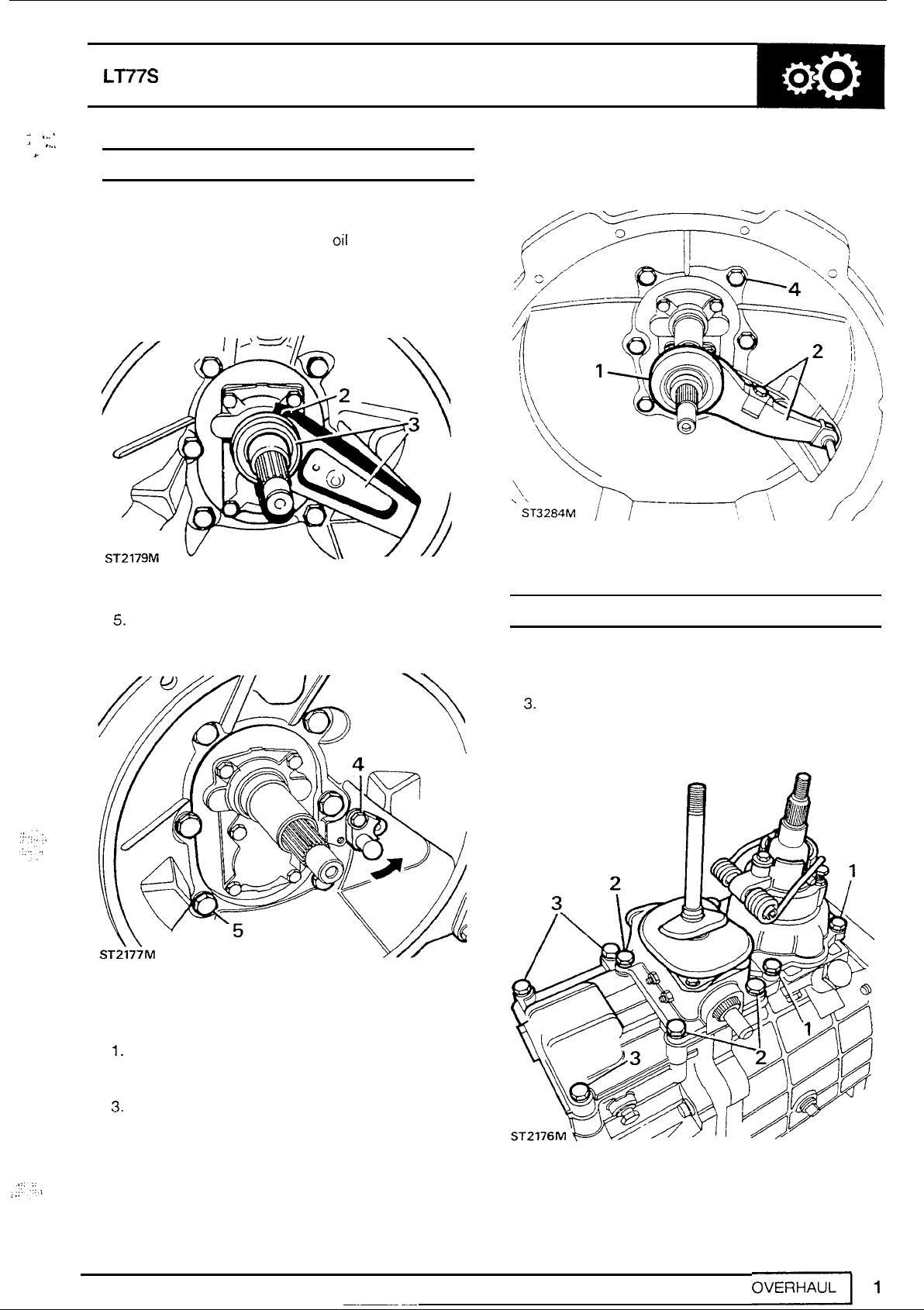
Bell housing
1.
Remove transfer box, drain
-
four cylinder engine
oil
and clean
exterior.
2.
If
fitted, clutch release bearing clip.
3.
Remove clutch release assembly.
4.
Remove one pivot post bolt, slacken the other
and move post aside.
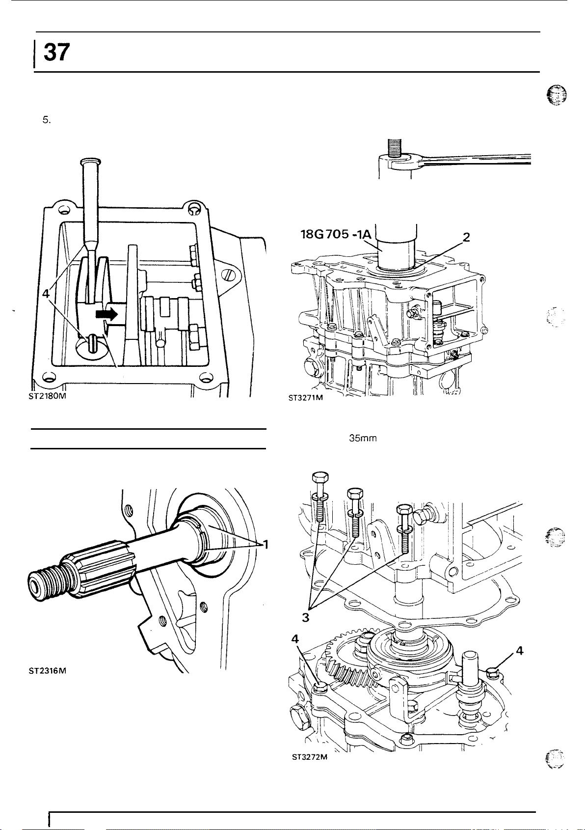
5.
Remove
six
bolts and withdraw bell housing.
GEAR
SELECTOR
1.
Remove four bolts and remove main gearbox
HOUSING
selector housing.
2.
Remove transfer box housing.
3.
Remove remaining bolts and remove remote
housing.
Bell housing
1.
Remove clutch release bearing.
2.
Remove screw and spring clip and remove
-
V8
engine
release lever.
3.
Remove
4.
Remove six bolts and bell housing.
"C"
clip from pivot post.
Page 6
I
37
4.
Drive out quadrant
5.
Move selector shaft forward to remove
quadrant.
MANUALGEARBOX
roll
pin.
2.
Using service
withdraw the oil seal collar.
tool
18G
&-
705
DEFENDER
and
18G 705
-
1A
n
5
ST2180M
EXTENSION
1.
Remove snap ring retaining oil seal collar.
HOUSING
.
18G 705
/U
3.
Remove the fifth gear extension housing.
4.
Secure the centre plate
two
8 x 35" bolts.
to
the gearcase with
ST2316M
2
I
OVERHAUL
Page 7
'..
':.
.:
r.
.,
~$
.:
I..
~.
LT77S
MAINSHAFT AND LAYSHAFT FIFTH GEARS
1.
Remove mainshaft
2.
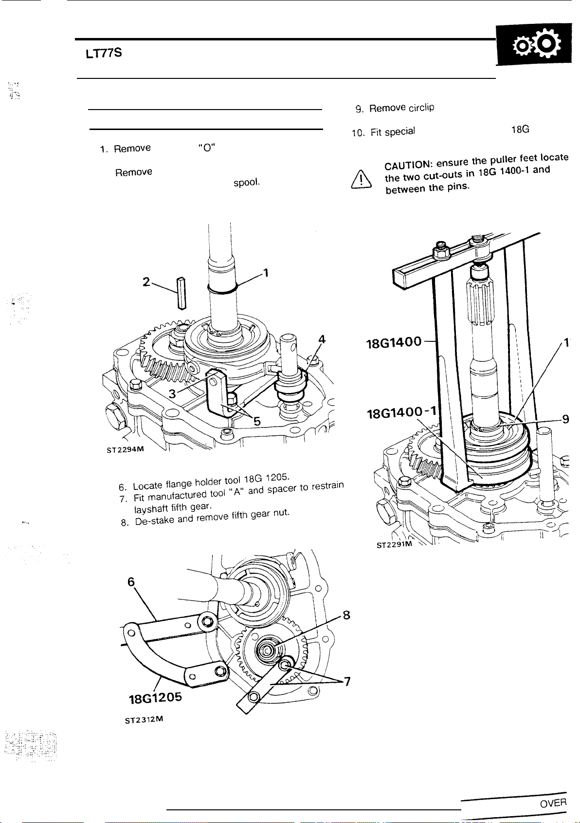
Remove
3.
Remove
4.
Remove fifth gear selector
5.
Remove selector fork bracket.
oil
pump drive shaft.
"E"
"0"
ring.
clips from selector fork.
Spool.
MANUAL
9.
Remove circlip retaining mainshaft fifth gear
GEARBOX
synchromesh.
10.
Fit special tool
18G
1400-1
and
18G
illustrated.
1400
as
..
..
Page 8
137
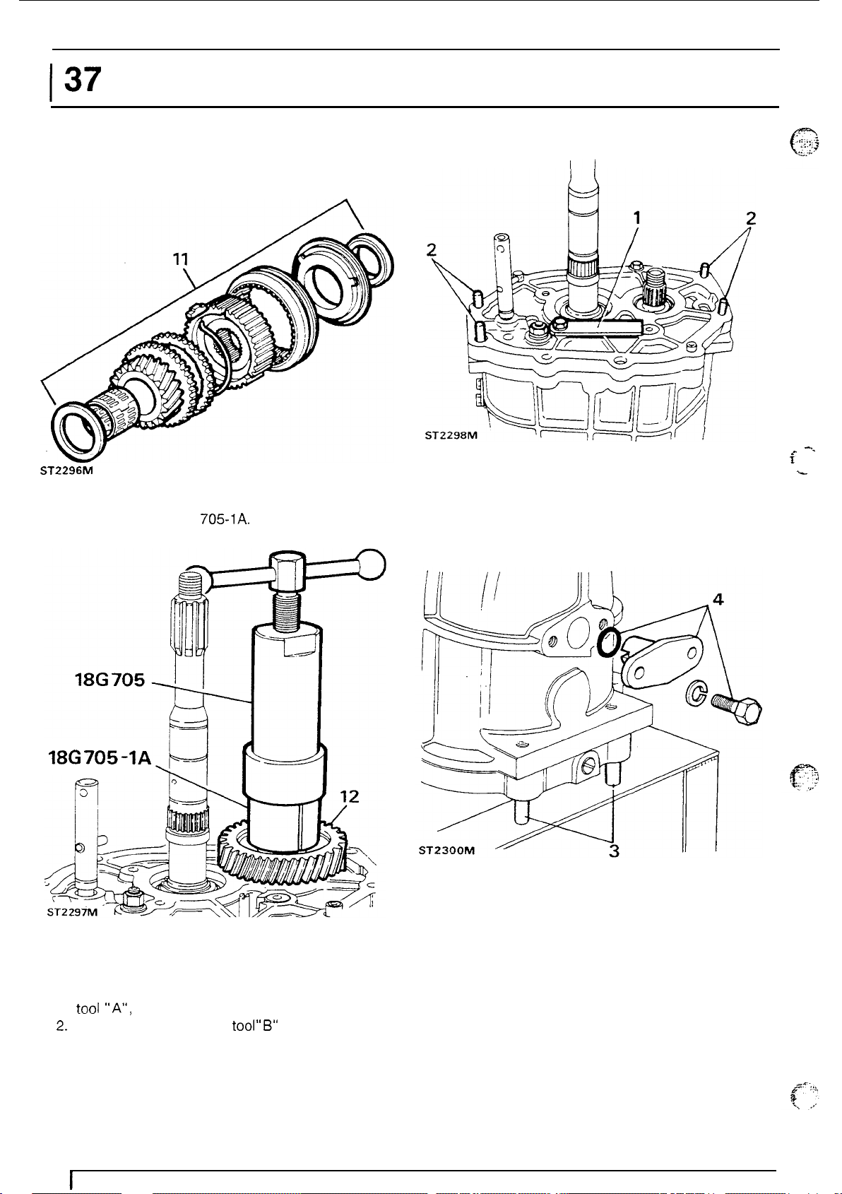
11.
Remove fifth gear synchromesh.
ST2296M
12.
Remove layshaft fifth gear using special tools
18G
MANUALGEARBOX
705
and 18G
705-1A.
DEFENDER
I1
3.
Invert gear case and locate studs in workstand
holes.
4.
Remove selector shaft spool retainer.
i
-.
-
18G705-1A
Main gear case.
1.
Secure reverse shaft retainer, manufactured
tool
"A";
to
centre plate.
2.
Fit
studs, manufactured
tool"B"
to gear case.
4
1
OVERHAUL
Page 9
LT77S
MANUAL
GEARBOX
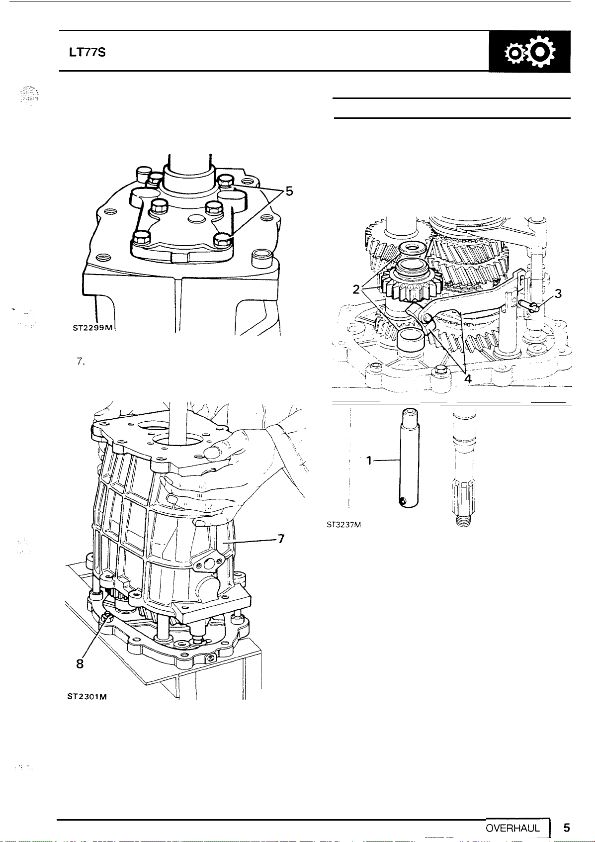
5.
Remove front cover and gasket.
6.
Retrieve selective washers.
7.
Remove
8.
Secure centre plate with nut and
bolts
and lift-off gear case.
bolt.
REVERSE
1.
2.
3.
4.
SHAFT,
Remove retainer (tool
Remove
spacer.
Remove reverse lever pin with
attached.
Remove lever and slipper pad.
LAYSHAFT
thrust
washer, reverse gear and
AND MAINSHAFT
"A"
)
and reverse shaft.
"E"
clip
ST23OlM
Yt
II
I
Page 10
I
37
5.
Remove input shaft and fourth gear baulk ring.
6.
Remove layshaft by tilting, as illustrated and
lifting mainshaft.
MANUALGEARBOX
DEFENDER
5
ST
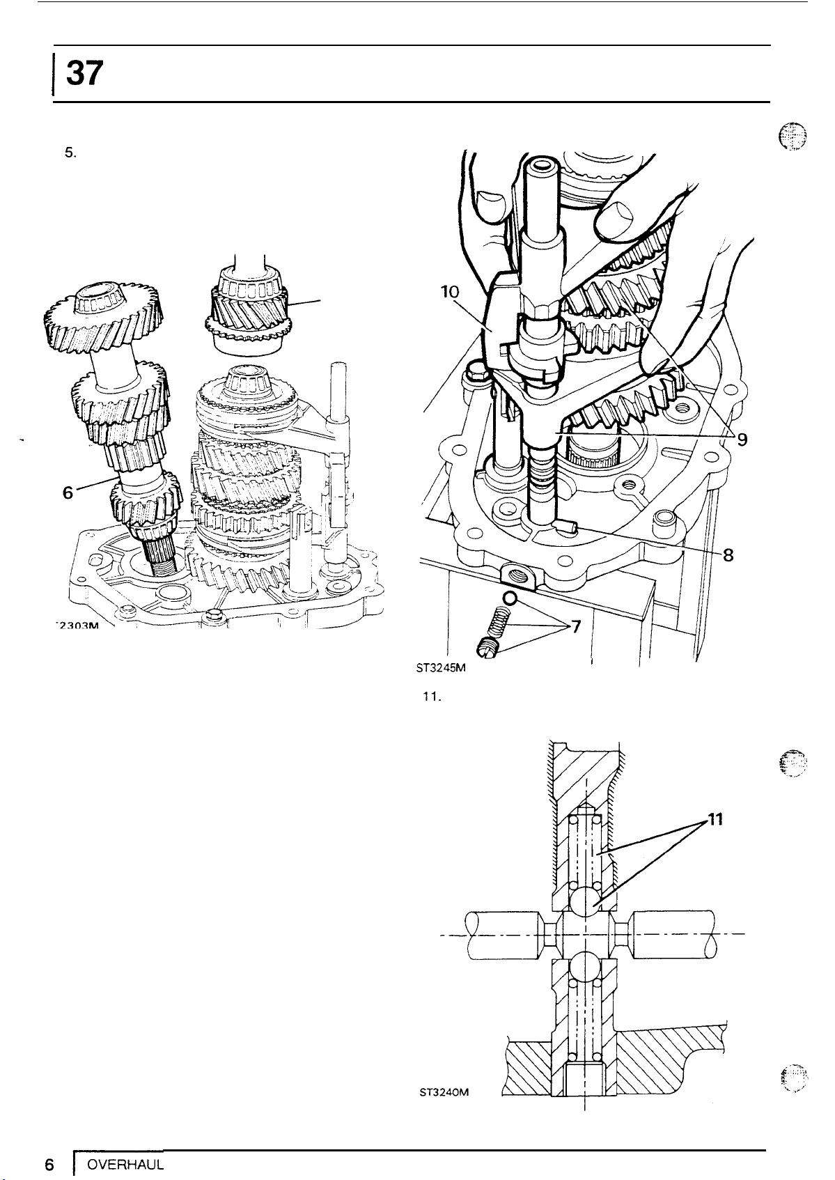
7.
Unscrew plug and remove spring and outboard
detent ball.
8.
Align fifth gear selector pin with centre plate
slot.
9.
Remove mainshaft, gears, selectors and forks.
10.
Remove selector fork assembly from gears.
ST3245
M
11.
Collect inboard detent ball and spring from
centre plate.
I
U
Page 11
Ll77S
c:".
..
.::
,
, . ,
I
I
. .
,
,..
.
..::.:,
,
...
...
1
..
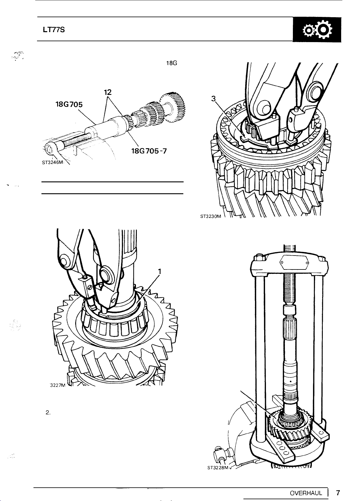
12.
Using extractor tool
705-7,
withdraw layshaft bearings.
18G
705
and collets
18G
MANUAL
GEARBOX
-.
ST3246M,
DISMANTLE
\
1.
Remove circlip retaining first gear assembly.
\
.
MAINSHAFT
4.
With
mainshaft.
MS
47
press
first
gear assembly from
r
-i
ST
2.
Remove taper bearing, bush, needle bearing,
first gear spacer, cone, inner and outer baulk
rings.
3.
Remove circlip
synchromesh assembly.
to
release
first
and second gear
4
R
I/
A
Page 12
137
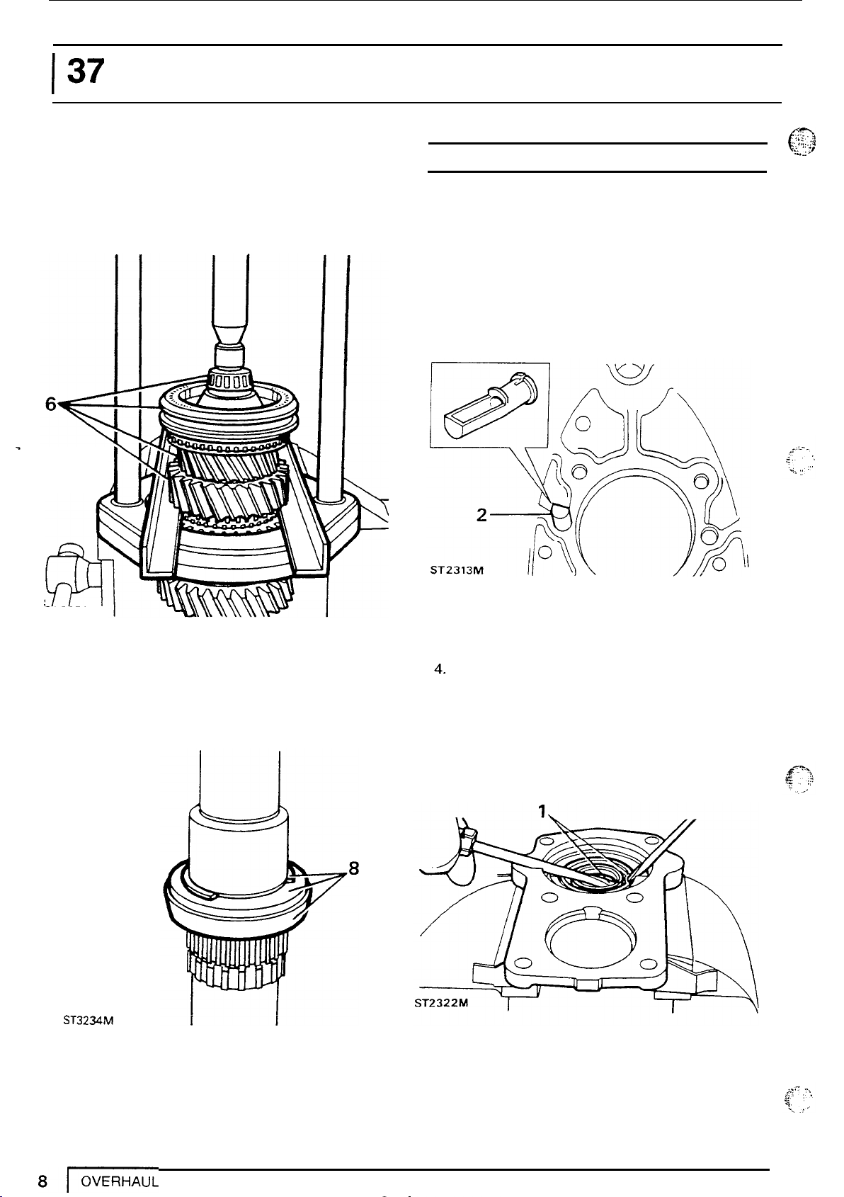
5.
Remove first and second synchromesh baulk
rings.
6.
Using
gear, press
synchromesh second and third gear assembly.
MANUALGEARBOX
MS
47 and support bars under second
off
pilot bearing, third, fourth
DEFENDER
GEARBOX CASINGS AND
Degrease and clean all components and discard
gaskets and seals.
Gearbox casing
1.
Remove mainshaft and layshaft bearing tracks.
2.
Remove plastic scoop from inside the casing.
OIL
PUMP
(3
L..
7
ST3326M
64
7. Remove washer, third, fourth synchromesh,
8.
i
third gear baulk ring, split needle rollers, bush,
needle bearing and second gear.
Remove snap ring, spacer, second gear cone
and circlip.
3.
Inspect case for damage, cracks and stripped
threads.
4. Fit a new scoop with scoop side towards top of
casing.
Front cover
1.
Remove oil seal from cover.
seal at this stage
Do
not fit a new
ST3234M
Page 13
LT77S MANUAL
3.
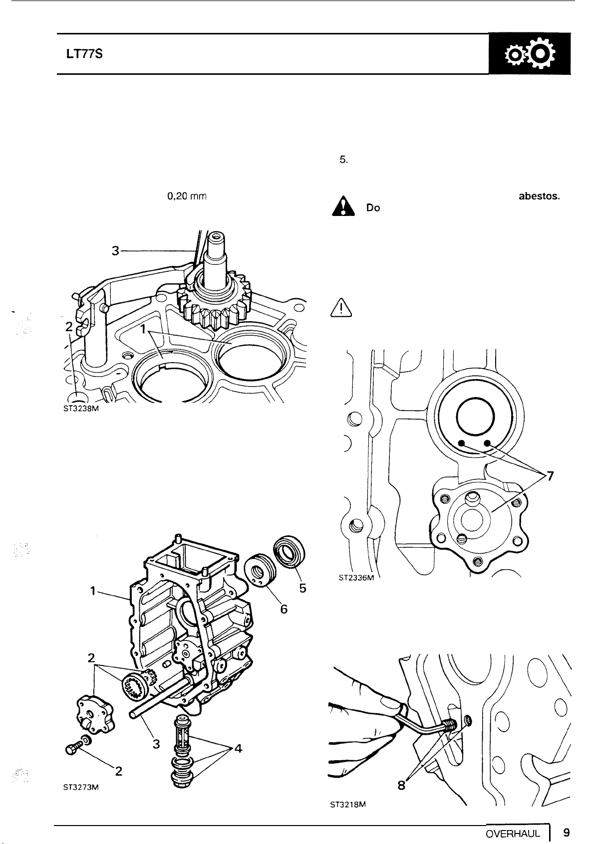
Centre plate
1.
Remove bearing tracks.
2.
Inspect for damage and selector rail bore for
wear.
3.
Temporally fit reverse shaft gear and lever and
check clearance between slipper and lever
does not exceed
0,20
mm
(0.008
in).
Check oil pick up pipe for obstruction but do
not remove.
4.
Remove drain plug assembly. Clean and renew
filter and washers if necessary.
5.
Renew oil seal.
6.
Renew Ferrobestos bush.
WARNING: This bush contains abestos.
A
substances.
A
Do
not attempt
INTRODUCTION,
7.
Fit
new bush with drain holes towards
casing.
CAUTION: If drain holes are not
positioned correctly oil may build up
behind oil seal and cause a leak.
GEARBOX
to
clean it. see
Information, Poisonous
bottom
of
ST3238M
Extension case
1.
Examine for damage
faces.
2.
Remove oil pump cover, inspect gears and
housing and renew if required.
to
threads and machined
8.
If extension housing is being renewed transfer
grub screw
threads.
to
new housing. Apply Loctite to
ST3218M
Page 14
I
37
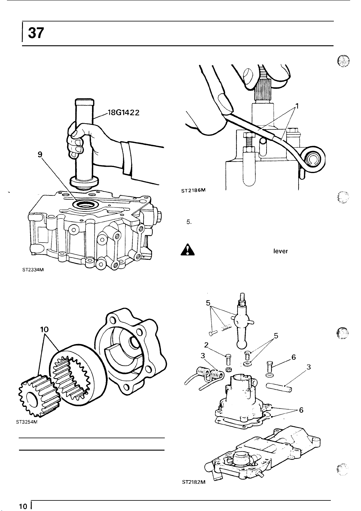
9.
Fit oil seal to housing, lip side leading, using
18G
MANUALGEARBOX
1422.
Apply
SAE
40
oil
to
lip.
DEFENDER
ST2186M
3.
Drive-out
4.
Remove gear lever extension from lower gear
lever.
5.
Remove bolt and special washer to remove
lower gear lever.
roll
pin
to
remove bias spring.
10.
Assemble gears to oil pump and fit cover.
WARNING: Hold
A
pad while removing the lever to prevent
causing personal injury.
6.
Remove gear selector housing from remote
housing.
the nylon spring loaded
it
ST3254M
GEAR CHANGE
1.
With a length of tube, release the bias spring
from adjusting screws.
2.
Remove bias spring adjusting screws.
10
I
OVERHAUL
HOUSING
Page 15
LT77S
,
"'
7.
Clean and examine all components and renew
where necessary.
8.
Assemble above parts
multi
-
purpose grease
In
reverse order using
on
gear lever.
MANUAL
10.
Remove circlip to release rollers and pin from
quadrant.
GEARBOX
NOTE:
properly located and that the lever
fitted
Ensure spring loaded pad
to
the housing with the pad on the
is
is
opposite side to the bias spring. Leave bias
spring adjusting screws slack until assembly
of
gearbox.
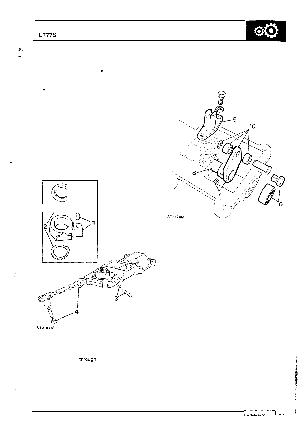
Remote gear
1.
Release socket headed screw
trunnion.
2.
Remove circlip to release seating from trunnion.
3.
1
.:
',
Remove fifth gear locknut and stud.
4.
Remove reverse gear plunger and shim.
I
/
lever
4,
housing.
to
remove
ST3274M
U
fg$y
ST2183M
5.
Remove fifth gear spool guide.
6.
Remove blanking plug.
7.
Drift-out roll pin securing quadrant
8.
With selector
9. Remove selector shaft
thr~ugh
hole.
"0"
ring.
to
shaft.
11.
Clean and examine all components and renew
where necessary.
12.
Assemble housing by first fitting
shaft.
13.
Fit quadrant and secure with roll pin.
14.
Fit rollers and secure with circlip.
15.
Fit fifth gear spool retainer and apply Loctite
290
to
bolt threads.
16. Apply Loctite
17.
Fit seating
18.
Fit trunnion
retaining screw threads.
19. Fit reverse gear plunger and original shims.
20.
Fit fifth gear stud stop and locknut.
21.
Fit new bucket plug with Hylomar
22.
Fit gear selector housing to remote housing.
290
to
reverse switch threads.
to
trunnion
to
shaft and apply Loctite to
and
"0"
ring
secure with circlip.
PL
32.
to
Page 16

37
MANUAL GEARBOX
DEFENDER
-
(,
.
-_
1
I
GEAR
SELECTOR HOUSING
1.:
t
I
0,:
i/'
1. Gear selector housing
2.
Gasket
3.
Roll
pin
14. Reverse gear plunger
15.
Gear
lever
Seating
16.
Trunnion
19.
'0'
ring
20.
Selector
21. Quadrant
22.
Roll
23.
Rollers
shaft
pin
i
Page 17

LT77S
MANUAL
GEARBOX
Reverse gear plunger assembly.
1.
Remove plug spring and ball.
2.
Remove circlip to release plunger and spring.
3.
Clean and examine components.
4.
Assemble plunger and spring with multi-purpose
grease and secure with circlip.
5.
Lubricate and fit detent ball and spring with light
oil. Apply Loctite 290 to plug threads and fit.
6.
Check that plunger returns when depressed.
NOTE:
A
10.
11. Fit
12. Insert shaft into fork and secure end cover with
13.
14.
15. Fit bushes
mutti-purpose grease on all moving
9.
Fit internal and external
assembly.
Fit detent spring.
"0"
of cross shaft.
screws.
Fit Nylon seat, groove downwards, to gear
lever.
Fit gear lever and seat to cross shaft and
secure with circlip.
pin and split pin.
Assemble the housing using
"0"
rings to
rings
to
end cover and fit to short end
to
gear lever and secure with clevis
parts.
fork
ST2201
Transfer gear housing.
M
1.
Remove the
assembly.
2.
Disconnect the gear lever from selector fork.
3.
Retrieve the non metallic bushes.
4.
Remove circlip to release ball and seat and
withdraw gear lever.
5.
Remove screws from end cover
cover and cross shaft.
6.
Remove selector fork.
7.
Remove detent spring and plate.
8.
Clean and examine ail parts and renew where
necessary.
four
screws and remove gaiter
to
withdraw
Page 18

137
15
MANUALGEARBOX
I
DEFENDER
-
12
ST
2185
M
1. Gaiter retaining screw
2.
Gaiter.
3. Gaiter support plate.
4.
Gate plate.
5.
Gasket.
6. Split pin.
7.
Clivis pin.
8. Circlip retaining Nylon seat.
9.
Gear lever ball.
Nylon
10.
seat.
-
4
off,
17
11. Cross shaft.
12. Gear lever.
13. Gear change housing.
14. Non
15. Counter sunk screws.
16. End cover.
17. Detent spring and plate.
18. Selector fork.
19.
-
mettalic bushes.
"0"
rings.
Page 19

LT77S MANUAL
SYNCHROMESH ASSEMBLIES
-
fourth and fifth gear synchromesh.
Third
NOTE: the above assemblies are the
same except that fifth gear synchromesh
has a retainer plate.
1.
Mark relationship of inner and outer members.
2.
Remove wire clip from both sides
of
assembly.
GEARBOX
3.
Remove slippers and separate the two
members.
4.
Examine all parts for damage and wear
including wire clips for tension.
5.
Check
members and mainshaft splines. (except fifth
gear synchromesh).
6.
Examine inner and outer splines for wear.
no
radial movement exists between inner
ST2803M
7.
Examine the dog teeth on
damage.
NOTE: example"A shows a tooth
a
good condition. Example"6" shows the
rounded corners of a worn tooth.
SR449M
all
U
gears
for
wear and
in
OVERHAUL
I
15
Page 20

137
MANUALGEARBOX
DEFENDER
First-second synchromesh
8.
Repeat instructions
synchromesh.
9.
Examine step in each
10.
Check that the step on both sides of the
internal splines are sharp not rounded.
NOTE: this applies only to splines on
selector groove side
1
to
6
for third-fourth
of
outer splines.
of
member.
12.
Fit the slippers and secure with a spring each
side
of
the synchromesh.
NOTE: The hooked end of each spring
must locate in the same slipper with the
free ends running
and
resting against the remaining slippers.
ST2467M
in
opposite directions
r;
ST3244M
\
11.
Fit
inner member to outer
splines of inner member are under the spur
gear teeth.
ST3247M
lb
so
that the wide
11
13.
Assemble third-fourth and fifth gear
synchromesh components as in instruction
NOTE: The back plate for fifth gear is
fitted to the rear of the assembly with the
single tag locating
member.
ST3276M
in
a
slot in the inner
12.
16
1
OVERHAUL
Page 21

LT77S MANUAL
GEARBOX
CHECKING BAULK RING CLEARANCES
Check clearance
of
all baulk rings and gears by
pressing the baulk ring against the gear and
measuring the
be
0,38mm (0.015in).
gap.
The minimum clearance should
First gear
Third gear
ST
Fourth gear
second gear
ST3259M
ST32
26M
Fifth gear
ST3261M
OVERHAUL
17
Page 22

I
37
MANUALGEARBOX
DEFENDER
INPUT SHAFT
1.
Examine the gear and dog teeth for wear and
damage.
2.
Polish oil seal track if necessary.
3.
Using
18G
284
AAH
and
18G
284
bearing track.
18G284AAH
\
18G284
ST3278M
4.
Using
18G 47BA
bearing.
and
MS
47
remove taper
remove pilot
6.
Using Press
adaptor
18G
MS
47
BAX
47,
Collets
fit a new taper bearing.
18G
478
and
..
.?.
:c
t
..-.
.
-
-\~
,
.
:.,
_r
NOTE: ensure that the bearing
0
ST3279M
supported by the
5.
Support the shaft under
new track.
lip
inside
MS
18G
47
and press
is
47
BA.
in
a
MAINSHAFT
1.
Examine bearing journals for wear and scores.
2.
Check condition
3.
Examine splines for wear and damage.
4.
Use an air line
from the pump is clear and feed
bearing.
5.
Check oil feed holes to roller bearings are clear.
of
circlip grooves.
to
check that the main oil feed
to
spigot
3
ST3241
M
Page 23

LT77S
MANUAL
GEARBOX
MAINSHAFT GEAR END FLOAT CHECKS
1.
Hold mainshaft in vice front end downwards.
2.
Fit front circlip
3. Fit second gear cone.
4.
Fit spacer.
5.
Fit snap ring.
ST3235M
for
first-second synchromesh.
-
Third gear end
1.
Fit needle roller
2.
fit third gear bush
3.
Place gear
downwards, and with
gear check clearance between straight edge
and gear.
ST3251
M
float.
to
third gear.
to
third gear.
on
flat surface, bush flange
a
straight edge across
Not
to exceed
0,20
(0.008in).
Second gear end-float.
1.
Fit needle roller and second gear
2.
Fit third gear bush.
3.
Check clearance between second gear and
bush flange.
4.
Remove above components.
Not
to
exceed 0,20
(0.008in).
First
gear bush end-float.
1.
Invert mainshaft rear end uppermost.
2.
Fit inner and outer second gear baulk rings.
ST3252M
'
'I\\
OVERHAUL
1
19
Page 24

1
37
MANUALGEARBOX DEFENDER
3. Fit first-second synchromesh hub, fork groove
uppermost.
4.
Fit circlip.
ST3231
-
First-second synchromesh assembly
M
8.
Fit first gear bush.
9.
Fit dummy bearing.
Fit
10.
11.
12.
circlip.
Check clearance between dummy bearing and
Not
to
bush.
Remove circlip, dummy bearing and bush.
exceed 0,75mm (0.003in).
9
8
7
S
T3
2
57M
5.
Fit first gear inner and outer baulk ring.
6.
Fit cone.
7. Fit spacer.
ST3
253M
Selective first gear bush
Part number Thickness
FTC2005
FTC2006
FTC2007
FTC2008
FTC2009
Check first gear to bush end-float.
1.
Fit roller bearing and bush
2. Place bush flange side downwards on a raised
block on a flat surface.
rest
on
1---7
I
NOTE:
the same diameter as the bush flange
that the gear is suspended and does not
the flat surface.
the block should be approximately
I
30,905/30,955
30,955131,005
31,005131,055
31,055/31,105
31
,
1
to
05/31
,155
first gear.
so
Page 25

LT77S MANUAL GEARBOX
3.
Place straight edge across gear and check
clearance between gear and straight
to exceed 0,20mm (0.008in).
'/
ST3255M
edge.Not
\
37
1
3
ASSEMBLING
1.
With the first-second synchromesh hub and
spacer in position, assemble the rear end
shaft.
2. Fit the roller bearing and bush to first gear.
3.
Fit first gear to mainshaft.
MAINSHAFT
of
the
4.
Fit the taper bearing to mainshaft using
collets
18G
47
BA
and adaptor
18G
MS47-
47
MS
BAX.
47,
ST3229M
First gear assembly
ST3262M
(.
OVERHAUL
121
Page 26

37
A
5.
Invert mainshaft and press assembly back
against circlip.
MS
MANUAL GEARBOX DEFENDER
CAUTION: Ensure that the slots in the
baulk ring align with the synchromesh
slippers while pressing on the bearing.
47’
5
\
7.
Posltlon mainshaft in vice, rear end downwards
and fit second gear needle roller, and second
gear.
8.
Fit third gear bush.
9.
Fit third gear needle
10.
Fit third gear.
11.
Fit third gear baulk ring.
rollers.
w
5
’2
ST3264M
NOTE: Instruction
is probable that when pressing on the
bearing it will have clamped the first gear
bush preventing
6.
Reposition mainshaft
driver blade check that the first gear bush is
free to turn.
LJ
5
it
from turning.
in
is
necessary since it
vice and using a screw
ST3256M
22
I
6’
OVERHAUL
ST3233M
Third-fourth synchomesh assembly
Page 27

LT77S MANUAL
12.
Fit third-fourth gear synchromesh hub.
13.
Using
MS
47
with
supports
press the spigot bearing
under first gear,
on
to
shaft.
-
1
2
LAYSHAFT
1.
Examine the layshaft for wear and damage.
2.
Press bearings
supporting bars.
GEARBOX
on
to
layshaft using
MS
47
and
ST3266M
"U/
MS.47
/
\
REVERSE GEAR AND SHAFT
1.
Remove one circlip from the idler gear and
remove bearings.
i
ST2466M
OVERHAUL
I23
Page 28

1
37
A
engagement. Renew bearings if worn or if the
gear jumps out of engagement.
MANUALGEARBOX DEFENDER
NOTE: One bearing cage is twisted in
manufacture. The twist causes the gear
to tilt on the shaft forcing the gear into
SELECTORS
1.
Examine selector rail and pins for wear and
damage.
Examine first-second selector fork for wear
2.
cracks and damage.
p
v
.
;
2.
Fit the bearings either way round and secure
with the circlip.
3.
Check condition of idler gear and mating teeth
on layshaft and synchromesh outer member.
NOTE:
only supplied as a complete assembly.
Examine third-fourth selector fork for wear,
3.
cracks and damage.
Examine fifth gear selector fork, pads and pivot
4.
pins.
Examine interlock spools for wear and damage.
5.
The the selector rail and fork
1
is
I
'!
..
.
...
....
.:
.
*i
.
..
ST2447M
4.
Examine idler shaft for wear. scores and oittina.
ST2482M
Renew retaining circlips if distorted.
6.
4
Page 29

LT77S
..
A
MANUAL
GEARBOX
Assembling selectors.
7.
Rest first-second fork and shaft assembly
bench and locate pin in jaw of fork.
8.
Fit interlock spool and third-fourth fork and
engage
ST2-M
9.
Slide spool and fork towards first- second
selector until
keeping the
jaw.
spool
8
in
jaw of fork.
7
slot
in
spool
locates over pin
spool
engaged in third-fourth fork
on
ASSEMBLING GEARBOX
SHAFTS
PLATE
Fitting gears to centre plate
1.
Secure centre plate
tracks and inboard detent ball and spring.
to
workstand,
TO
fit
CENTRE
bearing
ST2487M
ST3282M
I
2.
Check both synchromesh units are in neutral
and
fit
selector shaft assembly.
3.
Fit
J
mainshaft and selectors
slot
align pin with
in plate.
to
centre plate and
Page 30

137
4.
Fit layshaft While lifting mainshaft to clear
layshaft rear bearing.
5.
Turn selector shaft and interlock spool
reverse lever to engage spool flange.
6.
Fit reverse lever
pin and circlip.
7.
Fit slipper pad to lever.
8.
Fit reverse gear shaft, spacer and gear.
9.
Fit slipper
shaft engages
MANUALGEARBOX
to
pivot post and secure with
to
reverse gear and ensure
in
slot in centre plate.
to
roll
allow
pin in
DEFENDER
10.
Secure reverse shaft with manufactured tool
"A"
.
11.
Fit reverse gear thrust washer to shaft.
12.
Fit fourth gear baulk ring.
13.
Lubricate spigot bearing and fit input shaft.
14.
Remove centre plate workstand bolt and fit
gasket.
I
I
'9
I
.rU'
I
ST3239M
ST3267M
-1
ST2492M
26
I
OVERHAUL
10
R8
II
Page 31

LT77S MANUAL
2
>
-
I
:
GEARBOX
FITTING GEARBOX CASING
1.
Turn selector shaft and spool
to
neutral
position.
2.
Fit out-board detent ball and sprlng and secure
with plug.
ST2494M
3.
Fit guide studs to casing and check
correctly fitted.
4.
Without using force, fit gearcase.
NOTE: Ensure that the centre plate
dowels and selector shaft are properly
located.
5.
Secure centre plate and gearcase to workstand
8
x
with two
6.
Apply PL
fit
spool retainer.
35" bolts.
32
to joint face and bolt threads and
oil
2
scoop
ST2515M
CAUTION:,Do not use force to fit retainer.
A
position.
reposition spool
I
S
Provided the spool has not been
disturbed the retainer will slide into
If
not, remove the gear case and
or
shaft.
7.
Remove detent plug, apply Loctite 290 or
Hylomar PL
8.
Fit
layshaft and input shaft bearing tracks.
32
to thread, refit and stake.
OVERHAUL
27
Page 32

137
FITTING FIFTH
A
to the layshaft front bearing. Tool"D"and
packing disc should be made to the dimensions
given
to
the input shaft bearing outer track.
1.
Secure the plate with two 8x25" bolts. Insert
disc between plate and layshaft.
MANUALGEARBOX
GEAR
CAUTION:
fit on
pressing the gear, must not be transfered
absorb
Since the fifth gear is a tight
the
layshaft, the force, when
the
force. The plate also retains
-
4.
Fit a new stake nut but do not tighten.
5.
Fit fifth gear assembly to mainshaft.
DEFENDER
6%
';'
2. Release and invert gearbox and remove reverse
shaft retainer plate.
3.
With the extraction
gear
I,
ST2519M
on
to
layshaft using
I
groove
I
uppermost, drive fifth
18G
1422.
28
I
OVERHAUL
Page 33
;:::-:
...
!::.
. .
~.I,
..
,::.q
.
...
...
..
LT77S
I
..,
'
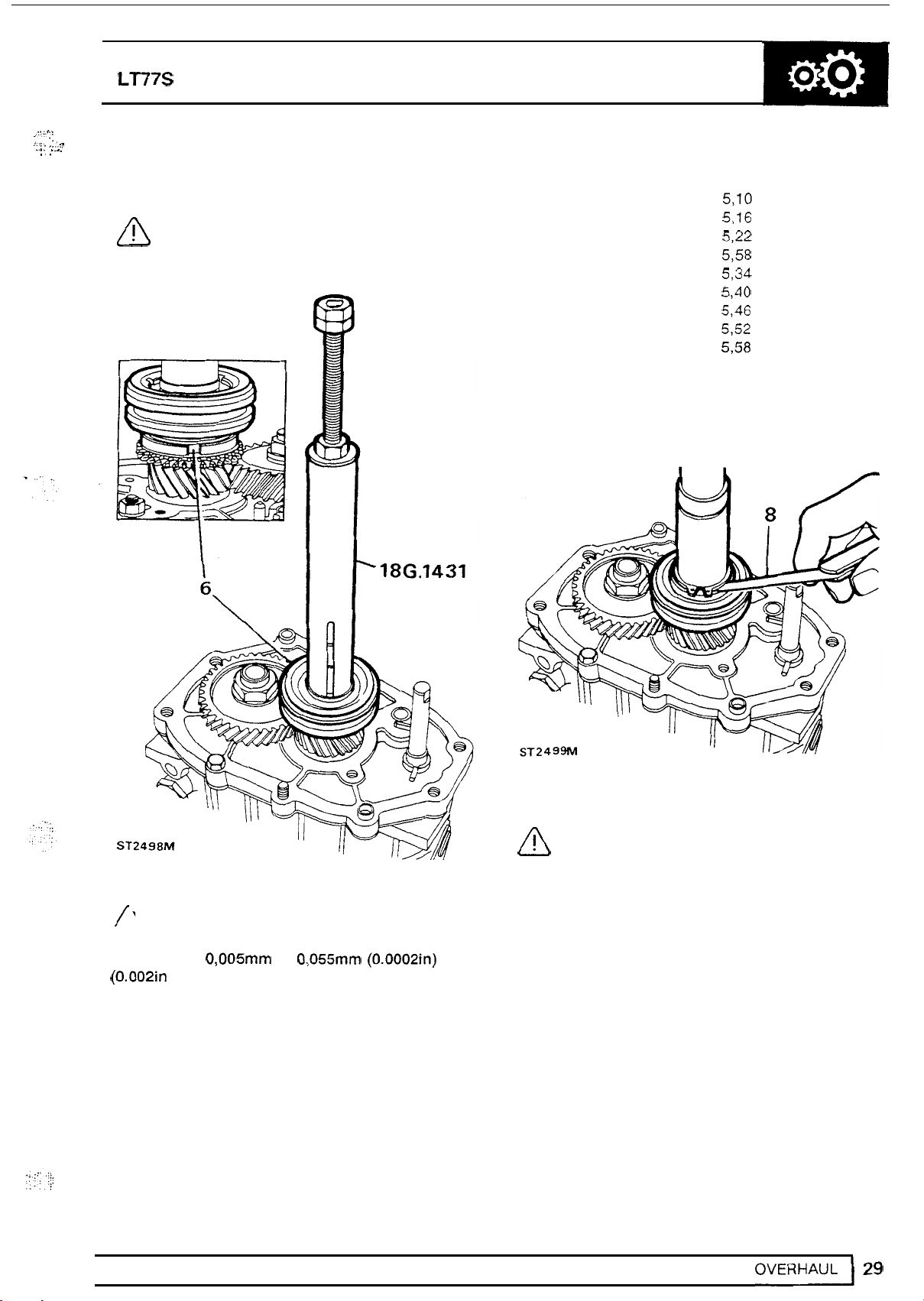
6.
Press fifth gear synchromesh assembly
mainshaft using
CAUTION: Before pressing the assembly
A
fully home, ensure that the slipper pads
locate
18G 1431.
in
the baulk ring slots.
to
MANUAL
Part number Thickness
5284
FRC
FRC
5286
FRC
5288
FRC
5290
FRC
5292
FRC
5294
FRC
5296
FRC
5298
FRC
5300
FRC
5302
7.
Fit the thinnest washer and secure with circlip.
8.
Measure clearance between circlip and washer,
GEARBOX
5,lO
5,16
5,22
5,58
5,34
5,40
5,46
5,52
558
5.64
NOTE:
synchromesh inner member on the
main
clearance is
(0.002in and to achieve this the following
selective washers are available.
Only
limited movement
-
shaft is permissable. The maximum
0,005" to 0,055mm (0.0002in) to
of
the
9.
Tighten layshaft stake nut using
CAUTION: The practice of locking gears
A
required.
to
provide a restraint
not acceptable due to
18G
to
tighten the
high
torque figure
1205.
nut
is
Page 34

1-37
MANUAL GEARBOX DEFENDER
10.
Secure
using a suitable torque wrench tighten the nut
to
11.
Using a round nose punch, form the collar into
the layshaft
tool
"A"
to gear and gear case and
the correct torque.
slots.
FIFTH
GEAR
1.
Fit fifth gear selector fork bracket.
2.
Fit the fifth gear spool long end towards centre
plate.
3.
Fit slippers to selector fork.
4.
Fit fork to synchromesh and secure with pins
and
SELECTOR
"E"
clips.
FORK
ASSEMBLY
NOTE: Before fitting pins and clips cover
A
holes in centre plate to prevent them
falling into casing.
5.
Engage tongue of spool in selector fork.
6.
Fit oil pump drive
to
layshaft.
Page 35

.
-.
.
,~.
:,'
.
....
,
..
.
.
LT77S
..
.f.
..
..
,..
EXTENSION CASE
MANUAL
GEARBOX
1. Release centre plate from workstand and
gasket on joint face.
2.
Fit
extension case
pipe.
Remove
while
guide
aligning oil pick-up
studs
and secure to main
case.
A
3.
Fit
NOTE:
remove case and re
if
CAUTION: To protect
fitting, cover mainshaft splines with
smooth tape.
"0"
Do
not use force, if necessary
-
align oil pump drive
case does not fit first time.
"0"
ring while
ring
to mainshaft groove.
fit
4.
ST2512M
4.
Fit
"0"
d'
ring
collar to mainshaft using 18G
1431
ST
'3221
M
U
7
OVERHAUL
~
I31
Page 36

137
INPUT-MAINSHAFT BEARING ADJUSTMENT
1.
Turn gearbox over with input shaft uppermost.
Remove layshaft support plate.
0
intended end float, and the bearings are not
-
loaded.
pre
2.
Measure the thickness of a new front cover
gasket.
3.
Place the original shim
and finger tighten the bolts.
4.
Measure the clearance between front cover and
gearcase with two feeler gauges.
MANUALGEARBOX DEFENDER
NOTE: Correct shimming of the
shaft bearing is vital to ensure that the
mainshaft assembly has the design
on
mainshaft bearing
input
Mainshaft selective washers
Part number
FRC
4327
FRC
4329
FRC
4331
FRC
4333
FRC
4335
FRC
4337
FRC
4339
FRC
4341
FRC
4343
FRC
4345
FRC
4347
FRC
4349
FRC
4351
FRC
4353
FRC
4355
FRC
4357
FRC
4359
FRC
4361
FRC
4363
FRC
4365
FRC
4367
FRC
4369
Thickness(")
!,63
1,81
1,87
1,93
1,99
2,05
2,ll
2,17
2,23
2,29
2.35
2,41
2,47
2,53
2,59
2,65
2,67
2,77
131
137
1,69
1,75
rj
I,
..
ST3269M'
5.
will have no pre
(0.0025in) end float.
6.
'
If required, change the selective washer
provide a clearance of 0,35mm to 0,085"
(0.001
thickness.
Remove front cover and keep gasket and
selective washer together.
to
O.OO3ins)
NOTE: This will ensure
gasket and cover is fitted to the correct
torque, the input and mainshaft bearings
-
load and.not more than 0,06mm
less than the gasket
that
to
when the
LAYSHAFT BEARING ADJUSTMENT
Place original selective washer
1.
bearing, fit front cover without gasket, and
finger tighten bolts.
Measure clearance, with two feeler gauges,
2.
between cover and gearcase. Select
that will provide a clearance equal to the
thickness of the gasket that was selected and
measured when calculating the adjustment of
the input and mainshaft bearing.
on
layshaft
a
shim
32
I
OVERHAUL
ST2503M
11
Page 37

LT77S MANUAL
A'.
..
NOTE: This will ensure zero layshaft
a
cover
torqued.
bearing end float
0,025"
and
gasket are fitted and bolts correctly
3. Remove cover and selected washer and fit new
oil seal, lip towards gearcase.
4. Fit mainshaft and layshaft selected washers and
gasket.
(0.001
and
not more than ASSEMBLY
in) pre-load once the
GEAR LEVER AND REMOTE HOUSING
1.
Fit
quadrant
NOTE: Push shaft forward, fit quadrant
a
so
rear. Return shaft to neutral position.
ledge
GEARBOX
to
selector shaft with new roll pin.
is
to the left viewing
box
from
4
ST2521M
5.
Wrap protective tape round input shaft splines.
6. Apply Hylomar PL 32 to
cover.
Layshaft selective washers.
Part number
FTC 0262
FTC 0264
FTC 0266
FTC 0268
FTC 0270
FTC 0272
FTC 0274
FTC 0276
FTC 0278
FTC 0280
FTC 0282
FTC 0284
FTC 0286
FTC 0288
FTC 0290
FTC 0292
FTC 0294
FTC 0296
U
bolt
threads and secure
Thickness(")
1,36
1,42
1,48
134
1,60
1,66
1,72
1,78
1,84
1,90
1,96
2,02
2,08
2,14
2,20
2,26
2,32
2,38
2. With a new gasket, fit remote housing locating
over dowels.
in
NOTE: Ensure rollers locate
a
Reverse gear plunger adjustment.
fork.
3.
Fit transfer gear change housing.
1.
Fit plunger with original shims and tighten
2. Slacken locknut, turn adjuster screw
dimension
in). Tighten locknut.
"A"
is
approximately 12 mm
A
/'
ST3223M
quadrant
so
-----
-
(
that
(0.50
-
bolts.
Page 38
137
MANUALGEARBOX
DEFENDER
NOTE: If necessary, final adjustment can
be made
load turn screw clockwise
anti-clockwise to reduce load.
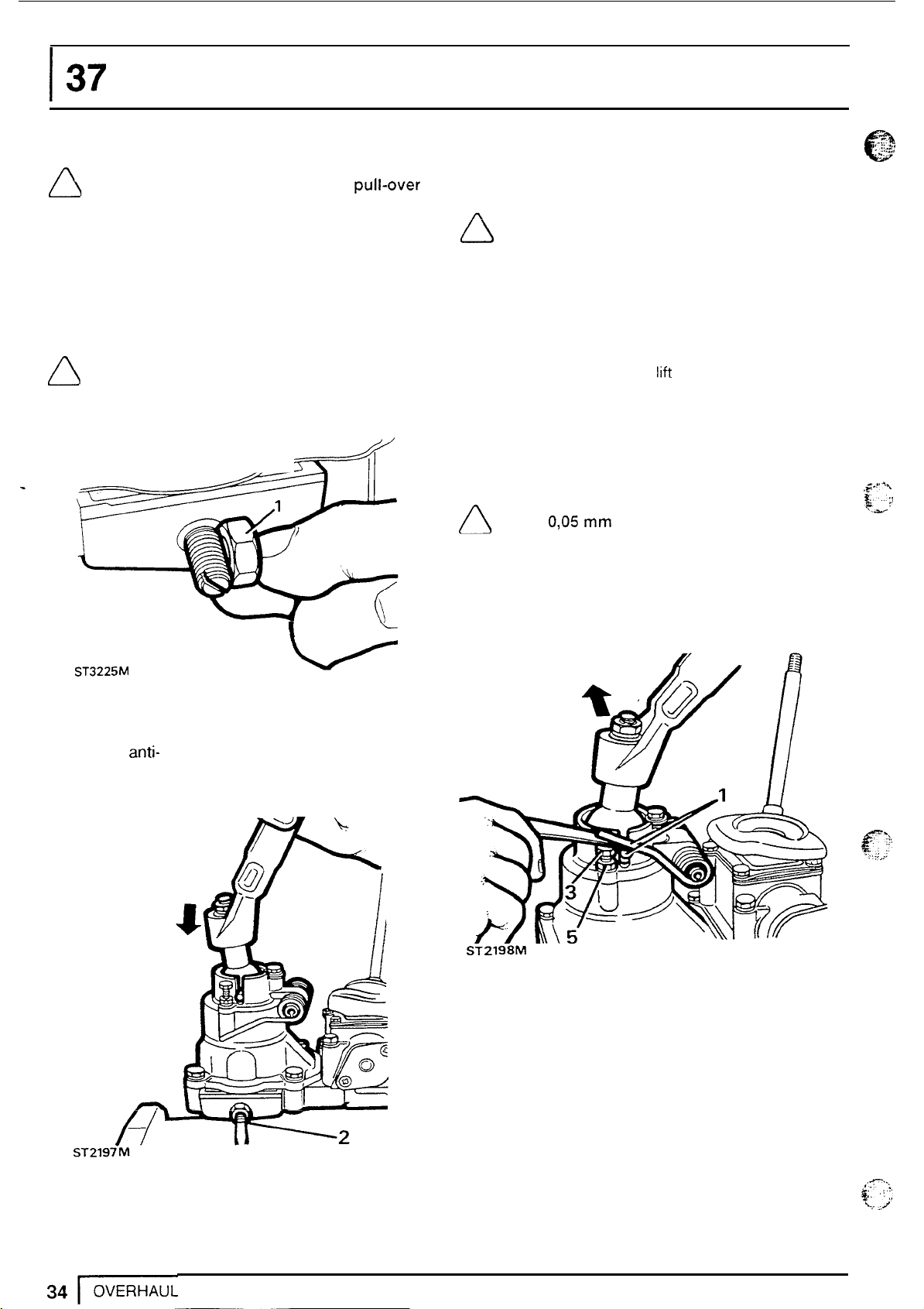
Fifth gear stop screw adjustment.
1.
Adjust screw to protrude from housing the
distance across corners
NOTE: This is only an approximate
setting which will limit travel of selector
yoke but will allow fifth gear to be
selected.
in
vehicle. To increase pull-over
of
locknut.
/
------
LA
I
or
Bias spring adjustment
NOTE: The purpose of this adjustment is
A
of the gear lever cross pin when third or fourth
gear is engaged. This will ensure that when
lever is
is automatically aligned for
selection.
//
L
to set both bolts
legs apply equal pressure on both ends
in
neutral, the gear change mechanism
1.
Select fourth gear and
the cross pins.
2.
Turn adjustment
legs.
3.
Apply light pressure
and adjust left hand bolt.
NOTE: Clearance between spring leg and
bolt
0,05
mm
gauge.
4.
Move lever to left and adjust right hand bolt
clearance.
5.
Tighten locknuts.
so
that the bias spring
third
or fourth gear
lift
both spring legs over
bolts
until heads touch spring
to
gear lever to the right
(0.002
in.) using feeler
the
to
,jy
$-:'
4%
ST3225M
2.
Select fifth gear. While applying light pressure
to
gear lever towards right, turn screw
clockwise until it contacts yoke. Turn screw half
a
turn anti- clockwise and tighten nut.
ST2198M
Page 39

LT77S
I
'8:
i
..
,I
BELL HOUSING - FOUR CYLINDER ENGINE
1.
Fit bellhousing locating over hollow dowels and
MANUAL
BELL HOUSING
1.
Fit bell housing locating
GEARBOX
-
V8
ENGINE
on
hollow dowels.
secure with bolts.
NOTE: Fit the
dowels and
12
x
45
12
x
30 mm bolts
mm bolts through
in
NOTE: Fit the
dowels and
positions.
12
x
45" bolts through
12
x
30" bolts in remaining
remaining positions.
2.
Apply molybdenum disulphide grease to pivot
2.
Secure pivot post.
3.
Apply molybdenum disulphide grease to pivot
post, lever pads and pins.
4.
Assemble pads to lever and lever to bearing
post, release lever, socket and push
the bearing guide.
Fit
'C'
3.
4.
washer to pivot post.
Fit spring clip to lever and fit lever to pivot post.
rod.
Not
and fit assembly to pivot post.
5.
Fit staple to release assembly, short leg to
lever.
NOTE: Position spring clip behind 'C'
washer and tighten screw.
NOTE: The staple is an aid to assembly
only which may become dislodged
or
lost in service without detriment.
5.
Fit bearing and retain with plastic staple.
ST2202M
4
ST3286M
4
4
L
Page 40

Page 41

..
..
LT77S
DATA
MANUAL
GEARBOX
Reverse lever and slipper pad clearance
Reverse gear plunger operating load
Synchromesh assemblies push through load
Clearance between baulk rings and gears
Fifth gear end float
Third gear end float
Second gear end float
First gear bush end float
First gear end float
Fifth gear synchromesh end float
TORQUE
A
correct torque.
VALUES
NOTE:
regularly checked for accuracy to ensure
all
that
............................................................
..........................................................
......................................................
...................................................
............................................................
......................................
Torque wrenches should be
fixings are tightened to the
Oil
pump
to
extension case
Clip
clutch release lever
Spool retainer
Spool guide
Extension case to gearcase
Pivot plate, clutch release
Remote housing
Gear lever housing
Guide, clutch release sleeve
Slave cylinder
Front cover to gearcase
Fifth gear support bracket
Plunger housing to remote housing
Gear lever retainer
Lower gear lever
Reverse lever pivot post nut
Clutch housing
Plug, detent spring and ball
Oil
drain plug
Oil filter plug
Oil filler
Breather
Fifth gear layshaft stake nut
Bottom cover
to
to
to
-
level plug
to
gearcase
remote housing
to
bell housing
to
to
gearbox bolts
clutch housing
..........................
................................
........................
gearcase
to
remote housing
bolts
extension nut
................_...
0,725 mm
45
to
55
8,2
to
10
0,38
mm
0,020 mm
0,020 mm
0,020 mm
0,075
mm
0,20
mm
0,005
to
0,055
kg
kgf
mm
Nm
7- 10
7
-
10
7 - 10
7
-
10
7- 10
22 - 28
22
-
28
22
-
28
-
28
22
22
-
28
22
-
28
22
-
28
22
-
28
7
-
10
40 - 47
-
28
22
65
-
80
-
28
22
47 - 54
65
-
80
-
35
25
14
-
16
204 - 231
7
-
10
SPECIFICATIONS,
TORQUE
Page 42

Page 43

LT77S
MANUAL
GEARBOX
SERVICE
injury and or damage to components.
18G 705 Puller, bearing remover
TOOLS
NOTE:
specified, only these tools should be
used to avoid the possibility of personal
Where the use of special tools
is
18G 1400
18G.7400-1
Remover synchromesh hub and
gear cluster
-.
__
8G 705
8G 705-7
-
ia~.705-
1A
oil
Adaptor for mainshaft
track and layshaft fifth gear
seal
0
Adaptor for layshaft bearings
8G
1400-1
MS47
1s
47 Hand press
186.47BA
Adaptor mainshaft fifth gear
8G
47BA
Adaptor input shaft bearing
SERVICE
TOOLS
1
Page 44

37
18G.47BAX
MANUAL
GEARBOX
DEFENDER
18G.1431
18G 47BAX Conversion kit
18G 284 Impulse extractor
18G
18G1205
18G
1431
1205
Mainshaft rear
Flange holder
oil
seal replacer
8G 284AAH
8G
1422
2
I
SERVICETOOLS
18G284AAH
Adaptor for input shaft pilot
bearing track
Mainshaft rear oil seal replacer
Page 45

"\
-
.
-
LT77S MANUAL GEARBOX
..
LOCALLY MANUFACTURED
In addition to the special service
tools can be locally made
and assembly of the gearbox. The following overhaul
procedure is based upon the assumption that these
tools
are available.
Tool
'A'.
Dual purpose tool. Reverse shaft retainer
prevent the shaft falling out when the gearbox in
inverted. Also, a layshaft fifth gear retainer to hold
the fifth gear whilst releasing stake nut. Use 5mm
mild steel to manufacture the tool. When using the
tool
for the layshaft nut, a suitable spacer is required
20" diameter 23" long, with an 8mm diameter
clearance hole.
TOOLS
tools,
the following
to
assist the dismantling
to
Tool
'C'.
Mild steel dummy centre bearing for the
selection of first gear bush.
C
A
ST2
15
4M
53.0"
-+
+
-
0.10
0.005
0-000
Tool
'B'.
Four pilot studs with an 8mm thread for
locating in the four counter sunk blind holes
workstand.
B
in
the
Tool
'D'.
Layshaft support plate
25" bolts and washers to the front of the gearbox
It
case.
track.
also supports the input shaft bearing outer
is
fitted with two 8
D
ST1118M
x
ST
21
55M
.
SERVICE
TOOLS
Page 46

137
Tool
'E'.
during overhaul. Manufacture from
angle iron. The single hole marked
drilled through the material with a
MANUALGEARBOX
Workstand for securely locating the gearbox
30"
10" drill.
1
'A'
should be
52mm
x
30"
DEFENDER
The four counter sunk blind holes marked
also be made with a
drilled through
I
64mm
lOmm drill, but must not be
the
material.
I
I
1
Omm
I
I
I
+
'B'
should
228"
80mm
+
I
I
I
4
SERVICE
ST2153M
TOOLS
Page 47

..
.
I.
... . .
.I
.,
,:
...
..
I:.
,.
.
.
.
...
,
!
::
*,;A.
.
...
..
,
..
,
.,
LT77S MANUAL GEARBOX
GEARS
10.
11.
12.
13.
14.
15.
16.
17.
18.
19.
20.
21.
22.
23.
24.
25.
26.
27.
28.
29.
30.
31.
32.
33.
34.
35.
36.
37.
38.
39.
40.
41.
42.
43.
44.
45.
46.
47.
48.
49.
50.
51.
AND
SHAFTS
1.
Third - fourth selector fork. 53.
2.
Interlock spool. 54.
3.
First
-
second fork and selector rail assembly.
4.
First - second synchromesh. 56.
5.
First gear synchromesh outer baulk ring. 57.
First gear synchromesh inner baulk ring. 58.
6.
7.
Cone.
Thrust washer.
8.
First gear.
9.
Needle roller bearings.
First gear selective bush.
Centre taper roller bearing.
Circlip.
Thrust washer.
Fifth gear.
Fifth gear baulk ring.
Fifth gear synchromesh.
Fifth gear synchromesh back plate.
Fifth gear synchromesh selective washer.
Circlip.
"0"
ring.
Oil
seal collar.
Snap ring.
Fourth gear baulk ring.
Pilot
taper bearing.
Spacer.
-
Third
fourth synchromesh.
Third gear baulk ring.
Third gear.
Third gear bush.
Second gear.
Thrust washer.
Cone.
Second gear synchromesh inner baulk ring.
Second gear synchromesh outer baulk ring.
Mainshaft.
Input shaft bearing track and selective washer.
Input shaft.
Input shaft taper bearing.
Fourth gear.
Selective shim.
Taper bearing.
Layshaft fourth gear.
Layshaft third gear.
Layshaft second gear.
Layshaft reverse gear.
Layshaft first gear.
Taper bearing.
Layshaft fifth gear.
Layshaft iifih gear retaining stake nut.
-
Circlips retaining first gear and first
second gear
synchromesh.
Snap ring retaining second gear cone and
52.
spacer.
Spacer.
Snap ring.
Reverse idler gear.
55.
Thrust washer.
Snap ring.
Fifth gear
spool.
SERVICE
TOOLS
5
Page 48

I
I
37
MANUALGEARBOX DEFENDER
Si3281
M
SERVICE TOOLS
Page 49

rc
..
,
,U,
LT77S
GEARBOX
1.
Front
2.
Front cover
3.
Front
4. Oil drain plug and washer.
5.
Oil
6. Gearbox main casing.
7.
Spool retainer.
8.
Gasket.
9.
Inboard detent ball and spring.
10.
Reverse lever and slipper.
11. Locating dowels
12. Reverse lever pivot
13. Centre plate.
CASING
cover.
oil
cover gasket.
level plug.
seal.
-
centre plate
post.
to
maincase.
MANUAL
GEARBOX
14. Selector plug, detent ball and spring.
15.
Gasket.
16. Fifth gear selector bracket.
17. Fifth gear selector
fork.
18. Reverse gear shaft.
19. Oil pick
-
up pipe.
20. Oil pump drive shaft.
Oil
21.
pump gears and cover.
22. Fifth gear extension housing.
23. Fifth gear extension housing drain plug and
filter.
24. Ferrobestos bush.
25.
Oil
seal.
'.
~ ~~
SERVICE TOOLS
Page 50

 Loading...