

Page 1

Overhaul Manual
LT230T
Verdeelbak revisieboek
LT230T
Boîte de transfert
Manuel de révision
LT230T
Verteilergetriebe
Überholungsanleitung
LT230T
Riduttore
Manuale di revisione
LT230T
Caja de transferencia
Manual de revisión
LT230T
Caixa de velocidades manual
Manual de revisão
LT230T
TRANSFER GEARBOX
Page 2
Dealer Stamp
Technical Information Review
While every attempt is made to ensure that the technical information we supply is as accurate and up to date as
possible, from time to time, errors do occur. There may also be instances where the style or content of our
publications do not meet your exact needs.
We would value your assistance in helping us to improve the quality of our publications and invite you to submit
details of any technical errors, or improvements you would like to see, in the space below.
Publication part number and edition.................................................................................................................
Publication title ...................................................................................................................................................
Section and/or pages affected ...........................................................................................................................
Technical information errors:
Other improvements/changes you would like us to consider:
Service manager’s signature ..........................................................................
Date ...................................................................................................................
Please return to:
Technical Communication, Rover Group After Sales, PO BOX 29,
Cowley, Oxford, OX4 5NL
Page 3

Page 4

LT230T
TRANSFER BOX
OVERHAUL
MANUAL
This transfer box is fitted to the following models:
Serial No. Prefixes 20D, 22D and 32D - Defender
Serial No. Prefixes 28D and 34D - Discovery
Serial No. Prefixes 14D, 15D, 20D, 26D, 27D, 28D
and 30D - Range Rover Classic
Publication Part No. LRL 0081ENG - 2nd Edition
Published by Rover Technical Communication
1997 Rover Group Limited
Page 5

Page 6

INTRODUCTION
CONTENTS
Page
INFORMATION
INTRODUCTION 1......................................................................................................
REPAIRS AND REPLACEMENTS 2...........................................................................
SPECIFICATION 2......................................................................................................
Page 7

Page 8
INTRODUCTION
INTRODUCTION 1
INTRODUCTION
How to use this manual
To assist in the use of this manual the section title is
given at the top and the relevant sub-section is given
at the bottom each page.
This manual contains procedures for overhaul of the
LT230T transfer box. For all other information
regarding adjustments and removal of oil seals,
consult the Repair Manual for the model concerned.
This manual is divided into 3 sections:
Description and Operation,
Overhaul and
Data, Torque & Tools.
To assist filing of revised information, each
sub-section is numbered from page 1.
Individual items are to be overhauled in the
sequence in which they appear in this Manual. Items
numbered in the illustrations are referred to in the
text.
Overhaul operations include reference to Service
Tool numbers and the associated illustration depicts
the tool. Where usage is not obvious the tool is
shown in use. Operations also include reference to
wear limits, relevant data, torque figures, specialist
information and useful assembly details.
WARNINGS, CAUTIONS and Notes have the
following meanings:
WARNING: Procedures which must be
followed precisely to avoid the possibility
of injury.
CAUTION: Calls attention to procedures
which must be followed to avoid damage
to components.
NOTE: Gives helpful information.
References
Operations covered in this manual do not include
reference to testing the vehicle after repair. It is
essential that work is inspected and tested after
completion and if necessary a road test of the
vehicle is carried out particularly where safety
related items are concerned
Dimensions
The dimensions quoted are to design engineering
specification with Service limits where applicable.
Page 9

INTRODUCTION
2
INTRODUCTION
REPAIRS AND REPLACEMENTS
When replacement parts are required it is essential
that only Land Rover recommended parts are used.
Attention is particularly drawn to the following points
concerning repairs and the fitting of replacement
parts and accessories.
Safety features and corrosion prevention treatments
embodied in the car may be impaired if other than
Land Rover recommended parts are fitted. In certain
territories, legislation prohibits the fitting of parts not
to the manufacturer’s specification.
Torque wrench setting figures given in this Manual
must be used. Locking devices, where specified,
must be fitted. If the efficiency of a locking device is
impaired during removal it must be renewed.
The terms of the vehicle Warranty may be
invalidated by the fitting of other than Land Rover
recommended parts. All Land Rover recommended
parts have the full backing of the vehicle Warranty.
Land Rover Dealers are obliged to supply only Land
Rover recommended parts.
SPECIFICATION
Land Rover are constantly seeking to improve the
specification, design and production of their vehicles
and alterations take place accordingly. While every
effort has been made to ensure the accuracy of this
Manual, it should not be regarded as an infallible
guide to current specifications of any particular
component or vehicle.
This Manual does not constitute an offer for sale of
any particular component or vehicle. Land Rover
Dealers are not agents of the Company and have no
authority to bind the manufacturer by any expressed
or implied undertaking or representation.
Page 10

TRANSFER BOX
CONTENTS
Page
DESCRIPTION AND OPERATION
FRONT OUTPUT HOUSING COMPONENTS 3.........................................................
DIFFERENTIAL COMPONENTS 5..............................................................................
MAIN CASING COMPONENTS 7...............................................................................
REAR OUTPUT HOUSING AND TRANSMISSION BRAKE COMPONENTS 9..........
DESCRIPTION 11.......................................................................................................
OPERATION 13...........................................................................................................
OVERHAUL
TRANSFER BOX DISMANTLING 1............................................................................
COMPONENT DISMANTLING 7.................................................................................
High/low cross shaft housing 7....................................................................................
Front output housing 7.................................................................................................
Rear output housing 10................................................................................................
Main casing 13.............................................................................................................
Mainshaft input gear bearing housing 13.....................................................................
Intermediate gears 14..................................................................................................
Mainshaft input gear assembly 14...............................................................................
Differential lock selector 15..........................................................................................
Differential 15...............................................................................................................
INSPECTING COMPONENTS 18...............................................................................
Intermediate gears and shaft 19..................................................................................
Mainshaft input gear 19...............................................................................................
High/low cross shaft and housing 20...........................................................................
Front output housing and differential lock selector 20..................................................
Rear output housing 22................................................................................................
Main casing 23.............................................................................................................
Mainshaft input gear bearing housing 23.....................................................................
High/low selector fork and shaft 24..............................................................................
Differential 25...............................................................................................................
COMPONENT ASSEMBLING 26................................................................................
Differential 26...............................................................................................................
Main casing 31.............................................................................................................
Mainshaft input gear bearing housing 32.....................................................................
Mainshaft input gear assembly 33...............................................................................
Intermediate gears 33..................................................................................................
Rear output housing 34................................................................................................
Front output housing 36...............................................................................................
High/low cross shaft housing 38..................................................................................
Differential lock selector 38..........................................................................................
TRANSFER BOX ASSEMBLING 39............................................................................
Mainshaft input gear bearing pre-load 39....................................................................
Rear output housing 40................................................................................................
Differential bearing pre-load 41....................................................................................
Front output housing 43...............................................................................................
Intermediate gears 46..................................................................................................
Intermediate gear bearing pre-load 48.........................................................................
Bottom cover 49...........................................................................................................
High/low selector shaft detent 50.................................................................................
Interlock solenoid - if fitted 50......................................................................................
Page 11

TRANSFER BOX
CONTENTS
Page
Neutral warning lamp switch - if fitted - not Range Rover Classic 51...........................
Differential lock warning lamp switch - adjust 51.........................................................
Transmission brake 52.................................................................................................
Page 12
TRANSFER BOX
CONTENTS
Page
DATA, TORQUE & TOOLS
DATA 1........................................................................................................................
TORQUE FIGURES 2..................................................................................................
SERVICE TOOLS 3.....................................................................................................
Page 13

Page 14

TRANSFER BOX
DESCRIPTION AND OPERATION 1
This page is intentionally left blank
Page 15

TRANSFER BOX
2
DESCRIPTION AND OPERATION
Page 16

TRANSFER BOX
DESCRIPTION AND OPERATION 3
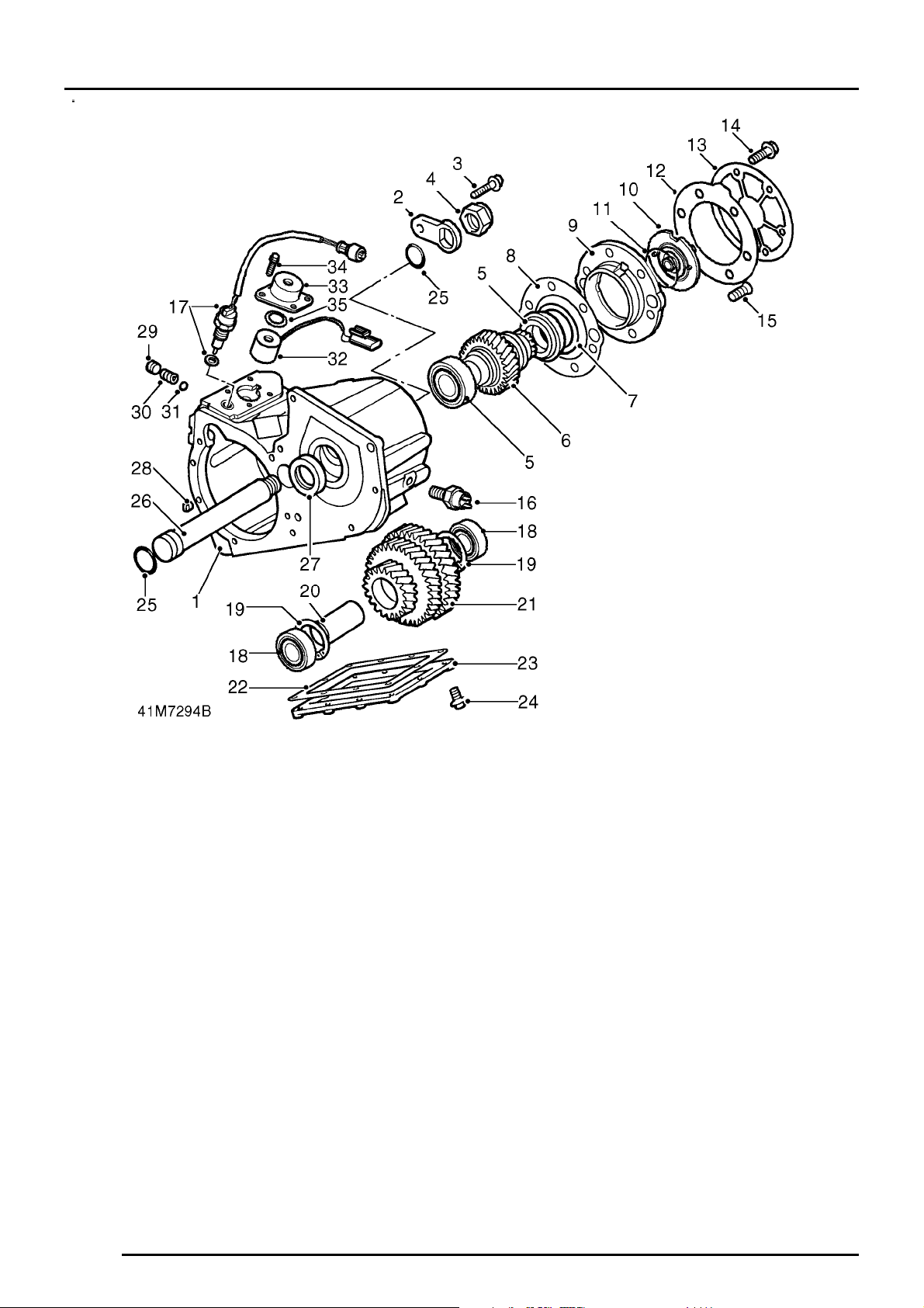
FRONT OUTPUT HOUSING COMPONENTS
1. High/low cross shaft housing
2. Bolt - high/low cross shaft housing
3. ’O’ ring
4. High/low cross shaft and lever
5. Dog clutch
6. Front output shaft
7. Hollow plug
8. Detent plug - differential lock
9. Detent spring - differential lock
10. Detent ball - differential lock
11. Differentiallock warning lamp switch
12. Locknut
13. Front output housing
14. Spring and clips - differential lock
15. Differentiallock selector fork
16. Side cover
17. Bolt - side cover
18. Bolt - front output housing
19. High/low selector finger
20. Differentiallock selector shaft
21. Plug
22. Bearing spacer
23. Output shaft bearing
24. Circlip
25. Oil seal
26. Output shaft flange and mud shield
27. Felt washer
28. Steel washer
29. Self-locking nut
30. Differentiallock selector finger and shaft
31. ’O’ rings
32. Differentiallock selector housing
33. Bolt - housing
34. Selector lever
35. Washer
36. Self-locking nut
37. Neutral warning lamp switch - Range Rover
Classic - if fitted
38. Gasket - high/low cross shaft housing *
39. Gasket - front output housing *
40. Gasket - side cover plate *
* Up to serial no. 288709E
Page 17
TRANSFER BOX
4
DESCRIPTION AND OPERATION
Page 18

TRANSFER BOX
DESCRIPTION AND OPERATION 5
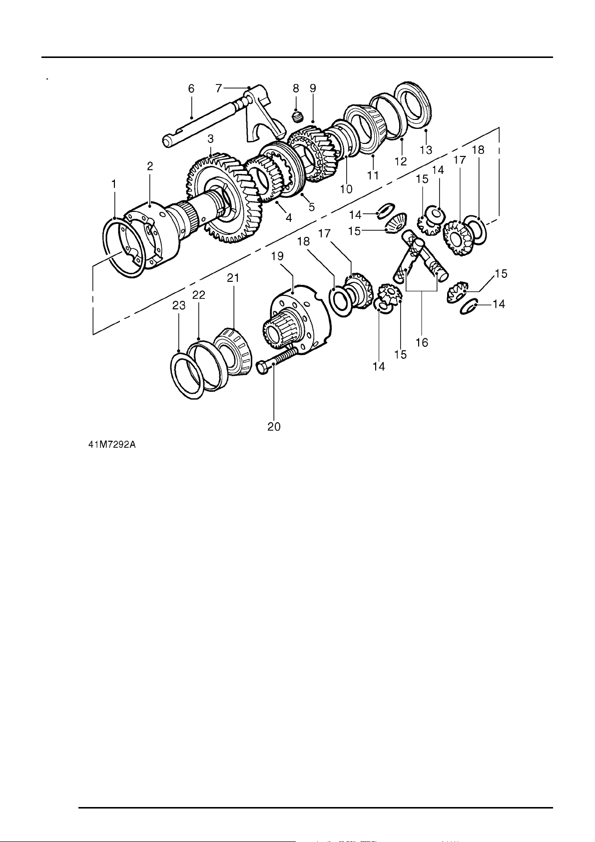
DIFFERENTIAL COMPONENTS
1. Retaining ring
2. Differentialcarrier - rear half
3. Low range gear
4. High/low hub
5. High/low selector sleeve
6. High/low selector shaft
7. High/low selector fork
8. Setscrew - high/low selector fork
9. High range gear
10. High range gear bush
11. Differentialrear bearing
12. Bearing outer track
13. Bearing retaining nut
14. Dished thrust washers
15. Planet gears
16. Cross shafts
17. Sun gears
18. Selective thrust washers
19. Differentialcarrier - front half
20. Bolt - differential carriers
21. Differentialfront bearing
22. Bearing outer track
23. Selective shim
Page 19
TRANSFER BOX
6
DESCRIPTION AND OPERATION
Page 20

TRANSFER BOX
DESCRIPTION AND OPERATION 7
MAIN CASING COMPONENTS
1. Main casing
2. Retaining plate
3. Bolt - retaining plate
4. Stake nut - intermediate shaft
5. Bearings and outer tracks - mainshaft input
gear
6. Mainshaft input gear *
7. Selective shim
8. Gasket **
9. Mainshaft input gear bearing housing
10. Oil feed plate ***
11. ’O’ ring ***
12. Gasket **
13. Cover plate/power take-offcover *
14. Bolt - cover plate
15. Countersunk screw - bearing housing
16. Oil temperature switch ***
17. Neutral warning lamp switch and washer - not
Range Rover Classic ***
18. Bearings and outer tracks - intermediate gears
19. Circlips
20. Collapsible spacer
21. Intermediategears
22. Gasket **
23. Bottom cover plate
24. Bolt - bottom cover plate
25. ’O’ rings - intermediate shaft
26. Intermediateshaft
27. Mainshaft oil seal
28. Locating dowel
29. Detent plug - high/low selector
30. Detent spring - high/low selector
31. Detent ball - high/low selector
32. Interlock solenoid ***
33. Cover - interlock solenoid ***
34. Bolt - interlock solenoid cover ***
35. Belleville washer ***
* Defender mainshaft input gear and Discovery
power take-off cover plate illustrated
** Up to serial no. 288709E
*** If fitted
Page 21
TRANSFER BOX
8
DESCRIPTION AND OPERATION
Page 22

TRANSFER BOX
DESCRIPTION AND OPERATION 9
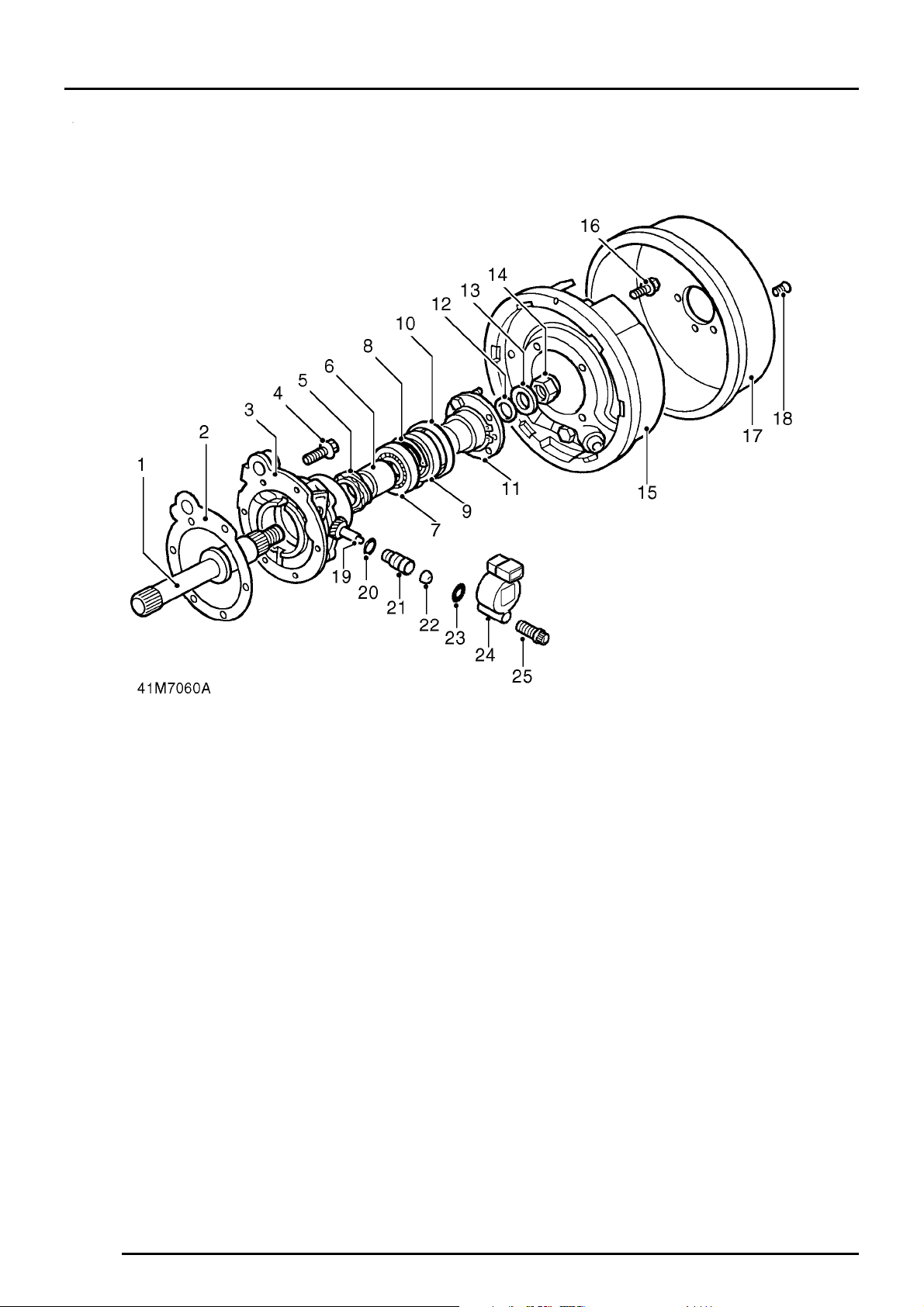
REAR OUTPUT HOUSING AND TRANSMISSION
BRAKE COMPONENTS
1. Rear output shaft
2. Gasket *
3. Rear output housing
4. Bolt - rear output housing
5. Speedometer drive gear
6. Spacer
7. Output shaft bearing
8. Circlip
9. Oil seal
10. Mud shield
11. Output shaft flange
12. Felt washer
13. Steel washer
14. Self-locking nut
15. Transmission brake backplate
16. Bolt - transmission brake backplate
17. Transmission brake drum
18. Countersunk screw
19. Speedometer driven gear
20. ’O’ ring
21. Speedometer driven gear housing
22. Seal
23. ’O’ ring **
24. Vehicle speed sensor **
25. Allen screw **
* Up to serial no. 288709E
** If fitted
Page 23
TRANSFER BOX
10
DESCRIPTION AND OPERATION
Page 24

TRANSFER BOX
DESCRIPTION AND OPERATION 11
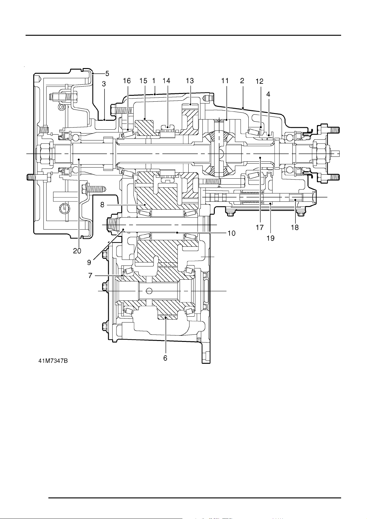
TRANSFER BOX CROSS SECTION
1. Main casing
2. Front output housing
3. Rear output housing
4. Dog clutch
5. Transmission brake
6. Mainshaft input gear
7. Selective shim - input gear bearing pre-load
8. Intermediategear cluster
9. Intermediateshaft
10. Collapsible spacer
11. Differentialassembly
12. Selective shim - differential bearing pre-load
13. Low range gear
14. High/low selector sleeve and hub
15. High range gear and bush
16. Differentialrear bearing
17. Front output shaft
18. Differentiallock selector shaft
19. Selector fork
20. Rear output shaft
DESCRIPTION
Introduction
The LT230T transfer box is mounted at the rear of
the main gearbox and transmits drive to the front
and rear axles via the propeller shafts.
Construction
The transfer box comprises three main assemblies,
the main casing, front output housing and rear
output housing.
The main casing carries the mainshaft input gear,
the intermediate gears and the differential together
with the high/low range gears, selector shaft and
fork.
The front output housing carries the front output
shaft and flange, high/low cross shaft, housing and
selector and the differential lock selector shaft and
fork. A dog clutch on the front output shaft is
operated by the differential lock selector fork to
engage/disengage the differential lock.
The rear output housing carries the rear output shaft
and flange and the speedometer drive and driven
gears. A mechanically operated transmission brake
is attached to the housing, the brake drum being
attached to the output flange.
All housings and cover plates are sealed to the the
main casing by gaskets or sealant; mud and water
ingress being prevented by mud shields and
throwers located at each end of the output housings
and on the drive flanges.
Mainshaft input gear
The gearbox output shaft is splined into the
mainshaft input gear which is supported by taper
roller bearings.
Input gear bearing pre-load is achieved by the use of
a selective shim located in the bearing housing. An
additional power take-off gear is located at the rear
of the input gear for certain applications.
Intermediate gears
The intermediate gear cluster is supported by taper
roller bearings located at each end of the cluster and
running on the intermediate shaft which, in turn, is
supported at the front and rear by the main casing.
Intermediate gear bearing pre-load is achieved by
means of a collapsible spacer positioned between
the bearings, the amount of compression applied to
the spacer is by means of a nut on the end of the
intermediate shaft.
Page 25

TRANSFER BOX
12
DESCRIPTION AND OPERATION
Differential assembly
The differential assembly is supported at the front
and rear by taper roller bearings, the bearing outer
tracks being located in the front and rear output
housings. Bearing pre-load is achieved by means of
a selective shim located in the front output housing.
The differential rear shaft carries the low range gear,
high/low selector sleeve and hub, high range gear
and bush and the differential rear bearing; these
components being secured to the shaft by a special
nut.
The differential assembly comprises front and rear
half carriers with integral shafts and sun and planet
gears mounted on cross shafts within the half
carriers. Dished, non-selective thrust washers
control the engagement of the planet gears with the
sun gears whilst selective thrust washers are used
to control the engagement of the sun gears and load
to turn of the differential. The differential carrier
halves are bolted together, a retaining ring providing
positive location of the cross shafts.
The high/low selector shaft and fork are located at
the side of the differential, movement of the shaft,
fork and selector sleeve being controlled by the
high/low selector finger. A spring loaded detent ball
fitted in the main casing, locates in grooves in the
shaft.
For certain markets, a neutral warning lamp switch
operated by the high/low selector shaft and an
interlock solenoid are fitted in the main casing.
Front output housing assembly
The front output shaft is supported in the front output
housing by a single bearing and is splined into the
differential front shaft.
The high/low cross shaft is located in a housing
bolted to the top of the output housing and is
connected to the high/low selector finger which
locates in a slot in the selector shaft.
The differential lock selector housing is also bolted
to the top of the front output housing, the selector
finger passes through the housing, locating in a slot
in the differential lock selector shaft. The differential
lock selector shaft passes through the selector fork
which is located beneath a plate bolted to the side of
the output housing. A spring loaded detent ball fitted
in the output housing locates in grooves in the shaft.
A differential lock warning lamp switch, operated by
movement of the selector fork and shaft is screwed
into the top of the output housing.
Range Rover Classic only
- For certain markets, a
neutral warning lamp switch operated by the
high/low cross shaft is screwed into the side of the
housing.
Rear output housing assembly
The rear output shaft is supported in the rear output
housing by a single bearing and is splined into the
differential rear shaft. The output shaft also carries
the speedometer drive gear which meshes with the
driven gear located in the rear output housing.
Lubrication
Lubrication is by splash, oil filler/level and drain
plugs being located in the main casing. An oil
temperature switch is also fitted for certain
applications.
Page 26

TRANSFER BOX
DESCRIPTION AND OPERATION 13
OPERATION
The gearbox output shaft transmits power to the
mainshaft input gear which is in constant mesh with
one of the intermediate gears. The intermediate
gears are in constant mesh with the high and low
range output gears running on the differential rear
shaft.
Power is transmitted to the output shafts by locking
either the high or low range gears to the differential
rear shaft. This is achieved by means of the high/low
selector fork, sleeve and splined hub.
The differential lock, when applied, prevents all
available power being transmitted to the road wheels
offering least resistance and is especially useful for
’off-road’ conditions. When selected, the selector
fork engages the dog clutch on the differential shaft
with a gear on the front output shaft; this locks the
differential and provides fixed drive thereby
transmitting equal power to both output shafts.
Page 27

Page 28

TRANSFER BOX
OVERHAUL 1
TRANSFER BOX DISMANTLING
1. Clean exterior of transfer box.
2. Drain and discard the oil, refit drain plug.
3. Slacken bolt to release transmission brake
adjustment.
4. Remove countersunk screw securing
transmission brake drum, remove drum.
NOTE: 2 screws may be fitted.
5. Make suitable alignment marks between
transmission brake backplate and rear output
housing.
6. Remove 4 bolts securing transmission brake
backplate, remove backplate.
7. Remove Allen screw securing vehicle speed
sensor - if fitted.
8. Remove vehicle speed sensor, remove and
discard ’O’ ring - if fitted.
9. Remove 6 bolts securing bottom cover, remove
cover.
10.
Up to serial no. 288709E:
Remove and
discard gasket.
Page 29

TRANSFER BOX
2
OVERHAUL
11. Release staking from intermediate shaft nut,
remove and discard nut.
12. Remove bolt securing anti-rotation plate,
remove plate.
13. Using a soft metal drift on threaded end of
intermediate shaft, drive shaft out of main
casing.
14. Remove and discard ’O’ ring from intermediate
shaft.
15. Remove and discard ’O’ ring from main casing.
16. Wrap a suitable length of wire around
intermediate gears and using assistance, lift
gears out of main casing.
17. Remove and discard 2 taper roller bearings
from intermediate gears.
18. Remove and discard collapsible spacer from
intermediate gears.
CAUTION: Do not remove bearing tracks
at this stage.
Page 30

TRANSFER BOX
OVERHAUL 3
NOTE: Discovery cover plate illustrated.
19. Make suitable alignment marks between cover
plate/power take-off cover, mainshaft input
gear bearing housing and main casing
20. Noting fitted position of stud nut and
harness/speedometer cable clip, remove 5
bolts and stud nut securing cover plate/ power
take-off cover, recover clip.
21. Remove cover plate/power take-off cover.
22.
Up to serial no. 288709E:
Remove and discard
gasket.
23. Remove oil feed plate - if fitted, remove and
discard ’O’ ring.
24. Remove 2 countersunk screws - if fitted
securing mainshaft input gear bearing housing.
25.
Up to serial no. 288709E:
Remove mainshaft
input gear bearing housing, remove and
discard gasket.
CAUTION: Do not remove mainshaft input
gear bearing track at this stage.
26.
From serial no. 288709E:
Remove mainshaft
input gear bearing housing.
CAUTION: Do not remove mainshaft input
gear bearing track at this stage.
Page 31

TRANSFER BOX
4
OVERHAUL
27. Remove mainshaft input gear together with
taper roller bearings.
NOTE: Input gear fitted to Defender
transfer boxes has an additional dog tooth
gear - see inset on illustration.
28. Remove and discard mainshaft oil seal from
main casing.
CAUTION: Do not remove mainshaft input
gear bearing track at this stage.
29. Remove 6 bolts securing high/low cross shaft
housing.
30. Remove cross shaft housing.
31.
Up to serial no. 288709E:
Remove and
discard gasket.
CAUTION: Do not carry out further
dismantling of cross shaft housing at this
stage.
Page 32

TRANSFER BOX
OVERHAUL 5
32. Slacken locknut and remove differential lock
warning lamp switch from front output housing.
33. Noting fitted position of longest bolt, remove 8
bolts securing front output housing to main
casing.
34. Remove front output housing.
NOTE: Dowel located.
35.
Up to serial no. 288709E:
Remove and
discard gasket.
CAUTION: Do not carry out further
dismantling of front output housing at this
stage.
36. Noting their fitted position, remove shoulder
bolt, 5 bolts and 2 washers securing rear
output housing to main casing.
37. Remove rear output housing.
NOTE: Dowel located.
38.
Up to serial no. 288709E:
Remove and
discard gasket.
CAUTION: Do not carry out further
dismantling of rear output housing at this
stage.
Page 33

TRANSFER BOX
6
OVERHAUL
39. Remove plug securing high/low selector shaft
detent spring and ball.
40. Remove detent spring.
41. Remove ball using a stick magnet.
CAUTION: Suitably identify plug, detent
spring and ball to their fitted positions, do
not interchange with differential lock
selector shaft detent components.
If fitted
42. Remove 4 bolts securing interlock solenoid
cover, remove cover and Belleville washer.
43. Remove interlock solenoid.
44. Remove neutral lamp warning switch and
washer.
All transfer boxes
45. Withdraw differentialassembly together with
high/low selector shaft and fork.
Page 34

TRANSFER BOX
OVERHAUL 7
COMPONENT DISMANTLING
High/low cross shaft housing
1. Slacken locknut and remove neutral warning
lamp switch - Range Rover Classic only - if
fitted.
2. Remove setscrew securing high/low selector
finger to cross shaft.
3. Withdraw cross shaft from housing, recover
high/low selector finger.
4. Remove and discard ’O’ ring.
Front output housing
1. Remove 7 bolts securing differential lock
selector side cover, remove cover.
2.
Up to serial no. 288709E:
Remove and
discard gasket.
3. Remove 3 bolts securing differential lock
selector housing, remove housing and selector
as an assembly.
4. Remove and discard ’O’ ring from selector
housing.
5. Remove plug securing differential lock detent
spring and ball.
6. Remove detent spring.
7. Remove ball using a stick magnet.
CAUTION: Suitably identify plug, detent
spring and ball to their fitted positions, do
not interchange with high/low selector
shaft detent components.
Page 35

TRANSFER BOX
8
OVERHAUL
8. Compress differentiallock selector fork spring
and remove retaining clip from each end of
spring.
9. Withdraw differentiallock selector shaft from
front output housing, recover spring.
10. Remove differentiallock selector fork.
11. Position propeller shaft flange holding tool
LRT-51-003 to output shaft flange.
12. Remove and discard self-locking nut.
13. Remove steel and felt washers, discard felt
washer.
14. Remove output shaft flange together with mud
shield.
NOTE: A replacement output flange will be
supplied together with new mud shield
and output shaft oil seal.
Page 36

TRANSFER BOX
OVERHAUL 9
15. Using a mallet, drive output shaft out of front
output housing.
NOTE: If it is necessary to use a hand
press to remove output shaft, position
thrust button LRT-370-11/2 between shaft
and press mandrel.
16. Noting its fitted position, remove dog clutch
from output shaft.
17. Noting its fitted position, remove bearing
spacer from output shaft.
18. Taking care not to damage front output
housing, remove and discard output shaft oil
seal.
19. Using suitable circlip pliers, remove and
discard circlip retaining output shaft bearing.
20. Support front output housing on suitable blocks
of wood.
21. Using a soft metal drift, drive output shaft
bearing out of housing; discard bearing.
Page 37

TRANSFER BOX
10
OVERHAUL
22. Invert front output housing.
23. Using a soft metal drift, drive differential
bearing track out of housing, discard bearing
track.
24. Remove selective shim.
Rear output housing
1. Position propeller shaft flange holding tool
LRT-51-003 to output shaft flange.
2. Remove and discard self-locking nut.
3. Remove steel and felt washers, discard felt
washer.
4. Remove output shaft flange together with
circlip.
NOTE: A replacement output flange will be
supplied together with new output shaft
oil seal.
Page 38

TRANSFER BOX
OVERHAUL 11
5. Carefully lever speedometer driven gear and
housing out of rear output housing.
6. Remove and discard ’O’ ring.
7. Withdraw speedometer driven gear from
housing, remove and discard oil seal from
housing.
8. Position rear output housing on bed of hand
press.
9. Position thrust button LRT-37-11/2 between
end of output shaft and press mandrel.
10. Press output shaft out of housing.
11. Recover spacer and speedometer drive gear
from output shaft.
Page 39

TRANSFER BOX
12
OVERHAUL
12. Using a screwdriver inserted in slot in rear
output housing, lever mud shield out of
housing.
CAUTION: Discard mud shield if it is
damaged.
13. Taking care not to damage rear output
housing, remove and discard output shaft oil
seal.
14. Using suitable circlip pliers, remove and
discard circlip retaining output shaft bearing.
15. Support rear output housing on suitable blocks
of wood.
16. Using a soft metal drift, drive output shaft
bearing out of housing; discard bearing.
Page 40

TRANSFER BOX
OVERHAUL 13
Main casing
1. Support main casing on suitable blocks of
wood.
2. Using a soft metal drift, drive differential rear
bearing track out of main casing; discard
bearing track.
3. Invert main casing.
4. Using a soft metal drift, drive mainshaft input
gear bearing track out of main casing; discard
bearing track.
Mainshaft input gear bearing housing
1. Secure mainshaft input gear bearing housing in
a soft-jawed vice.
2. Using a soft metal drift, drive input gear
bearing track out of housing; discard bearing
track.
3. Remove selective shim.
Page 41

TRANSFER BOX
14
OVERHAUL
Intermediate gears
1. Secure intermediate gears in a soft-jawed vice.
2. Using a soft metal drift, drive intermediate shaft
bearing track out of gears; discard bearing
track.
3. Remove and discard circlip.
4. Repeat above procedure for remaining bearing
track.
Mainshaft input gear assembly
NOTE: Defender input gear illustrated.
1. Secure hand press LRT-99-002 in a vice.
2. Assemble collars LRT-41-003 around bearing
to be removed.
3. Position mainshaft in hand press, remove and
discard bearing.
4. Repeat above procedure for remaining
bearing.
Page 42

TRANSFER BOX
OVERHAUL 15
Differential lock selector
1. Remove and discard self-locking nut retaining
selector lever.
2. Remove washer and selector lever.
3. Withdraw selector finger and shaft from
housing.
4. Remove and discard ’O’ ring.
Differential
1. Secure differential in a soft-jawed vice.
2. Remove staking from bearing retaining nut.
3. Remove nut using tool LRT-41-007; discard
nut.
Page 43

TRANSFER BOX
16
OVERHAUL
4. Secure hand press LRT-99-002 in a vice.
5. Secure collars LRT-41-001 around rear
bearing.
NOTE: This bearing is adjacent to
threaded end of differential shaft.
6. Position differential in hand press with thrust
button, part of tool LRT-41-001 between press
mandrel and differential shaft.
7. Press differential out of bearing.
CAUTION: Take care that differential does
not drop out of bearing.
8. Remove differential from press, discard
bearing.
9. Remove high range gear and bush taking care
not to disturb high/low selector sleeve.
10. Make suitable alignment marks between
high/low selector sleeve and hub.
11. Remove high/low selector sleeve.
Page 44

TRANSFER BOX
OVERHAUL 17
12. Using a suitable puller and thrust button, part
of tool LRT-41-001, remove high/low hub and
low range gear.
13. Secure hand press LRT-99-002 in a vice.
14. Assemble collars LRT-41-002 around front
bearing.
NOTE: This bearing is adjacent to splined
end of differential shaft.
15. Position differential in hand press with thrust
button, part of tool LRT-41-001 between press
mandrel and differential shaft.
16. Press differential out of bearing.
CAUTION: Take care that differential does
not drop out of bearing.
17. Remove differential from press, discard
bearing.
Page 45

TRANSFER BOX
18
OVERHAUL
18. Secure rear half of differential carrier in a
soft-jawed vice.
19. Make suitable alignment marks between front
and rear halves of differential carrier.
20. Remove 8 bolts securing front half of carrier to
rear, remove carrier.
21. Suitably identify front sun gear to front half of
carrier, remove sun gear.
22. Remove and discard thrust washer.
23. Suitably identify each planet gear to its shaft
and fitted position of each cross shaft to rear
half of carrier.
24. Remove retaining ring.
25. Remove planet gears and cross shafts, remove
and discard dished thrust washers.
26. Suitably identify rear sun gear to rear half of
carrier, remove sun gear.
27. Remove and discard thrust washer.
INSPECTING COMPONENTS
1. Clean all components, remove all traces of
silicone sealant using suitable solvent and a
plastic scraper.
2.
Up to serial no. 288709E:
Remove all traces of
gasket using suitable gasket removal spray
and a plastic scraper.
3. Clean all traces of Loctite and sealant from
threads of bolts and tapped holes. Ensure
holes are clean and dry.
CAUTION: Do not use a tap to clear
threads in tapped holes.
4. Check all casings and covers for cracks and
damage.
5. Replace any component found to be damaged.
Page 46

TRANSFER BOX
OVERHAUL 19
Intermediate gears and shaft
1. Check gear teeth for cracks, chipping and
uneven wear.
2. Check shaft for wear and threads for damage.
Mainshaft input gear
1. Check gear teeth for cracks, chipping and
uneven wear.
2. Check that cross drillings in shaft are clear.
NOTE: Early transfer boxes fitted with an
oil feed plate do not have cross drilled
shafts. If a replacement input gear and
shaft is to be fitted, the shaft will be cross drilled
and it will not be necessary to fit the oil feed
plate.
Defender only
3. Check that ends of dog teeth are not
rounded-off or chipped.
Page 47

TRANSFER BOX
20
OVERHAUL
High/low cross shaft and housing
1. Check mating surfaces of cross shaft and
drilling in housing for wear.
2. Check core plug in housing for signs of
leakage or corrosion, apply Loctite 326 to
replacement plug.
3. Check high/low selector finger for wear.
4. Measure across widest portion of finger:
Finger width = 15.90 to 15.95 mm (0.625 to
0.627 in)
Front output housing and differential lock
selector
1. Check bearing track recesses in housing for
damage, rectify or replace housing as
necessary.
2. Check differential lock selector finger shaft and
drilling in housing for wear.
3. Check differential lock selector finger for wear.
4. Measure across widest portion of finger:
Finger width = 15.90 to 15.95 mm (0.625 to
0.627 in)
5. Check differential lock selector finger groove
width in differential lock selector shaft:
Groove width = 16.0 to 16.1 mm (0.63 to 0.64
in)
Page 48

TRANSFER BOX
OVERHAUL 21
6. Check detent grooves in differential lock
selector shaft for wear.
7. Check differential lock detent ball for flat spots.
8. Check detent spring for distortion.
9. Check differential lock selector fork for cracks
and wear.
10. Check differential lock selector fork finger
width:
Finger width = 7.92 to 7.97 mm (0.311 to 0.313
in)
11. Check differential lock selector fork spring for
distortion and clips for wear and damage.
12. Check spring free length:
Free length = 84.58 mm (3.33 in)
13. Check dog clutch internal teeth and grooves for
wear and damage.
Page 49

TRANSFER BOX
22
OVERHAUL
14. Check dog clutch selector fork groove width:
Groove width = 8.05 to 8.20 mm (0.32 to 0.33
in)
15. Check threads and splines of output shaft for
damage and wear.
16. Check dog clutch teeth on shaft for wear and
damage.
Rear output housing
1. Check bearing track recess in housing for
damage, rectify or replace housing as
necessary.
2. Check speedometer drive and driven gears for
damage and wear.
3. Check splines and threads of output shaft for
damage and wear.
Page 50

TRANSFER BOX
OVERHAUL 23
Main casing
1. Check bearing track recesses in main casing
for damage, rectify or replace casing as
necessary.
2. Remove drain plug, discard sealing washer.
3. Fit new sealing washer, fit drain plug and
tighten to 30 Nm (22 lbf.ft).
4. Remove filler plug, check threads for damage.
5. Fit but do not fully tighten filler plug.
6. Check that locating dowels are fitted in casing
and that blade of front output housing dowel is
positioned as shown.
7. Remove oil temperature switch - if fitted,
remove sealant from threads of switch and
main casing.
8. Apply Hylomar PL32 sealant to threads, fit and
tighten switch.
9. Check high/low detent ball for flat spots.
10. Check detent spring for distortion.
Mainshaft input gear bearing housing
1. Check bearing track recess in housing for
damage, rectify or replace housing as
necessary.
Page 51

TRANSFER BOX
24
OVERHAUL
High/low selector fork and shaft
NOTE: There is no need to remove
selector fork from shaft unless fork or
shaft is to be replaced. If fork is removed,
coat threads of setscrew with Loctite 290 prior to
assembly.
1. Check detent grooves in shaft for wear.
2. Check high/low selector finger groove width in
shaft:
Groove width = 16.0 to 16.1 mm (0.63 to 0.64
in)
3. Check high/low selector fork for cracks and
wear.
4. Check high/low selector fork finger width:
Finger width = 7.37 to 7.47 mm (0.290 to 0.294
in)
Page 52

TRANSFER BOX
OVERHAUL 25
Differential
1. Check sun and planet gears for wear, cracks
and chipping of teeth.
2. Check cross shafts and recesses in both
halves of differential carrier for damage and
wear.
CAUTION: Ensure planet gears are
retained with their respective shafts.
3. Check retaining ring for distortion.
4. Check splines of differential shafts for wear
and damage.
5. Check teeth of high/low hub for cracks,
chipping and uneven wear.
6. Check selector fork groove width in high/low
hub:
Groove width = 7.5 to 7.6 mm (0.295 to 0.30 in)
7. Check splines and teeth of high/low selector
sleeve for uneven wear, cracks, damage and
chipping.
8. Check teeth of high and low range gears for
cracks, chipping and uneven wear.
9. Check high range gear bush for wear and
damage.
Page 53

TRANSFER BOX
26
OVERHAUL
COMPONENT ASSEMBLING
1. Lubricate all components with recommended
oil.
Differential
1. Lightly oil threads of differential bolts.
2. Secure rear half of differential carrier in a
soft-jawed vice.
3. Fit each planet gear to its respective
cross-shaft, fit new dished thrust washer to
each gear.
4. Fit cross-shafts, planet gears and dished thrust
washers in rear half carrier.
CAUTION: Ensure that cross-shafts are in
their correct fitted position in rear half
carrier. Do not fit sun gear into rear half
carrier at this stage.
5. Fit retaining ring.
6. Fit a 1.05 mm (0.04 in) thick thrust washer to
front half carrier sun gear, position gear in front
half carrier.
NOTE: This is the thinnest of the thrust
washers available.
7. Fit front half carrier to rear ensuring that
alignment marks are together.
8. Fit bolts and tighten by diagonal selection to 60
Nm (44 lbf.ft).
9. Insert front output shaft into front half carrier,
check that gears rotate freely.
10. Fit output flange on to splines of output shaft,
do not fit flange nut at this stage.
11. Fit transmission brake drum to output flange,
secure drum using 2 nuts.
12. Secure a length of cord around brake drum,
attach one end of cord to a spring balance.
13. Tension cord and note load to turn figure
recorded on spring balance when brake drum
rotates.
NOTE: Used gears should rotate smoothly
whilst new gears will have a ’notchy’ feel
as they rotate.
14. Check figure obtained against specified load to
turn figure:
Used gears = 0.45 kg (1.0 lb)
New gears = 1.72 kg (3.8 lb)
Page 54

TRANSFER BOX
OVERHAUL 27
15. If load to turn figure is below that specified,
proceed as follows.
16. Remove front output shaft together with brake
drum.
17. Remove 8 bolts securing front half differential
carrier.
18. Remove front half differential carrier.
19. Remove front half carrier sun gear and thrust
washer.
20. Select a thicker thrust washer from the range
available.
NOTE: 5 thicknesses of thrust washers are
available rising in increments of 0.10 mm
(0.004 in) from 1.05 to 1.45 mm (0.04 to
0.06 in) .
21. Position selected thrust washer and sun gear
in front half carrier.
22. Fit front half carrier to rear ensuring that
alignment marks are together.
23. Fit bolts and tighten by diagonal selection to 60
Nm (44 lbf.ft).
24. Fit front output shaft and brake drum and
repeat load to turn check.
25. Repeat above procedures as necessary until
load to turn figure is as specified; record final
figure obtained.
26. Remove brake drum from front output shaft,
remove output shaft.
27. Remove bolts securing front half carrier.
28. Remove front half carrier, remove sun gear
and thrust washer.
CAUTION: Keep selected thrust washer
with sun gear.
29. Remove retaining ring.
30. Remove planet gears and cross shafts.
31. Fit a 1.05 mm (0.04 in) thick thrust washer to
rear half carrier sun gear, position gear in rear
half carrier.
32. Fit planet gears, cross shafts and dished thrust
washers in rear half carrier.
CAUTION: Ensure that planet gears are
fitted to their respective cross-shafts and
cross-shafts are fitted in their correct
location in half carrier.
33. Fit retaining ring.
34. Fit front half carrier to rear ensuring that
alignment marks are together.
CAUTION: Do not fit sun gear and thrust
washer into front half carrier.
35. Fit bolts and tighten by diagonal selection to 60
Nm (44 lbf.ft).
Page 55

TRANSFER BOX
28
OVERHAUL
36. Invert assembly in vice and then insert rear
output shaft into rear half carrier, check that
gears rotate freely.
37. Fit output flange on to splines of output shaft,
do not fit flange nut at this stage.
38. Fit transmission brake drum to output flange,
secure with 2 nuts.
39. Carry out load to turn check using same
method as for front half carrier.
40. When load to turn figure is correct, record final
figure.
41. Upon completion, fit sun gear and selected
thrust washer to front half carrier.
42. Fit front half carrier ensuring that alignment
marks are together.
43. Fit bolts and tighten by diagonal selection to 60
Nm (44 lbf.ft).
44. With differential assembled, fit rear output shaft
and brake drum and check overall load to turn.
This should be approximately equal to total
load to turn figure of both front and rear half
carriers added together:
Used gears = 0.90 kg (2.0 lb)
New gears = 3.44 kg (7.6 lb)
45. Secure rear half carrier in a soft-jawed vice.
46. Fit a new front bearing using tool LRT-41-008.
Page 56

TRANSFER BOX
OVERHAUL 29
47. Support front half carrier in a soft-jawed vice.
48. Fit low range gear ensuring that dog teeth on
gear are towards threaded end of shaft.
NOTE: Use a suitable hollow mandrel to fit
gear if it is tight on splines.
49. Fit high/low hub ensuring that alignment mark
made during dismantling is towards threaded
end of shaft.
50. Fit high/low selector sleeve ensuring that
alignment marks on hub and sleeve are
together.
51. Fit bush to high range gear ensuring that collar
on bush is on opposite side of gear to the dog
teeth.
52. Fit high range gear and bush ensuring that
collar on bush is towards threaded end of
shaft.
53. Fit a new rear bearing using tool LRT-41-008.
54. Fit a new bearing retainer nut, tighten to 72 Nm
(53 lbf.ft) using tool LRT-41-007.
CAUTION: Do not stake nut at this stage.
Page 57

TRANSFER BOX
30
OVERHAUL
55. Slide high/low selector sleeve and hub away
from low range gear.
56. Using feeler gauges, determine clearance
between low range gear and high/low hub:
Clearance = 0.05 to 0.15 mm (0.002 to 0.006
in)
57. If clearance is not as specified, fit a new low
range gear and high/low hub and re-check.
58. Slide high/low selector sleeve and hub away
from high range gear.
59. Using feeler gauges, determine clearance
between high range gear and high/low hub:
Clearance = 0.05 to 0.15 mm (0.002 to 0.006
in)
60. If clearance is not as specified, fit new high
range gear and high/low hub and re-check.
Page 58

TRANSFER BOX
OVERHAUL 31
61. Using a round nosed punch, stake collar of nut
into recess in differential shaft.
Main casing
1. Fit a new differential rear bearing track using
tool LRT-51-009.
2. Using a straight edge and feeler gauges, check
that bearing track is recessed 1.0 mm (0.04 in)
below outer face of main casing.
3. Using a suitable mandrel, fit a new mainshaft
input gear bearing track.
CAUTION: Ensure bearing tracks are
seated squarely in recesses.
Page 59

TRANSFER BOX
32
OVERHAUL
4. Lubricate a new mainshaft oil seal with
recommended oil.
5. Invert main casing and fit oil seal, lip side
facing inwards, using tool LRT-37-014.
Mainshaft input gear bearing housing
1. Ensure bearing track recess in housing is
clean.
2. Position a 3.15 mm (0.12 in) thick shim in
bearing housing.
NOTE: This is the the thinnest of the
shims available.
3. Using a suitable mandrel, fit new mainshaft
input gear bearing track.
CAUTION: Ensure bearing track is seated
squarely in recess.
Page 60

TRANSFER BOX
OVERHAUL 33
Mainshaft input gear assembly
1. Lubricate new bearings with recommended oil.
2. Secure hand press LRT-99-002 in a vice.
3. Position collars LRT-41-003 in hand press.
4. Position new bearing on collars.
NOTE: Smallest diameter of bearing must
be towards collars.
5. Locate end of mainshaft in bearing, press
mainshaft through bearing.
6. Repeat above procedure for remaining
bearing.
Intermediate gears.
1. Lubricate new bearings and bearing tracks with
recommended oil.
2. Fit new circlips into intermediate gears.
CAUTION: Ensure that circlips are
correctly seated.
3. Fit new bearing tracks using tools LRT-41-006
and LRT-99-003.
CAUTION: Ensure bearing tracks are fully
seated against circlips.
4. Retain bearings with intermediate gears.
Page 61

TRANSFER BOX
34
OVERHAUL
Rear output housing
1. Heat rear output housing to 100 °C (210 °F).
2. Fit new output shaft bearing using tool
LRT-41-011.
3. Allow housing to air cool.
4. Fit new bearing retaining circlip ensuring it is
seated in groove.
5. Lubricate a new output shaft oil seal with
recommended oil.
6. Fit oil seal using tool LRT-41-012.
NOTE: Use end of tool marked ’REAR’ to
fit oil seal.
7. Check that oil seal is just contacting circlip.
8. Slide speedometer drive gear and spacer on to
output shaft.
Page 62

TRANSFER BOX
OVERHAUL 35
9. Position rear output housing on bed of hand
press.
10. Locate threaded end of output shaft in bearing.
11. Position thrust button LRT-37-11/2 between
end of output shaft and press mandrel.
12. Press output shaft into bearing.
13. Fit mud shield with open face of shield towards
oil seal.
CAUTION: Do not fit output shaft flange at
this stage.
Page 63

TRANSFER BOX
36
OVERHAUL
14. Fit speedometer driven gear into rear output
housing ensuring that gear teeth are engaged
with drive gear.
15. Lubricate a new ’O’ ring with recommended oil
and fit to driven gear housing.
16. Fit driven gear housing.
17. Lubricate a new oil seal with recommended oil,
fit seal with lip towards driven gear housing.
Front output housing
CAUTION: Do not carry out assembly
operations until differential bearing
pre-load has been established
- See
Differential bearing pre-load.
1. Heat front output housing to 100 °C (210 °F).
2. Fit new output shaft bearing using tool
LRT-41-011.
3. Allow housing to air cool.
4. Fit new bearing retaining circlip ensuring it is
fully seated in groove.
Page 64

TRANSFER BOX
OVERHAUL 37
5. Lubricate a new output shaft oil seal with
recommended oil.
6. Fit oil seal using tool LRT-41-012.
NOTE: Use end of tool marked ’FRONT’ to
fit oil seal.
7. Check that oil seal is just contacting circlip.
8. Position selected shim in front output housing.
9. Fit differential front bearing track using tool
LRT-54-003.
10. Fit bearing spacer to output shaft ensuring that
chamfer on spacer is towards threaded end of
shaft.
11. Fit dog clutch ensuring that flange on clutch is
towards splined end of shaft.
12. Using a mallet, drive output shaft into bearing.
Page 65

TRANSFER BOX
38
OVERHAUL
High/low cross shaft housing
1. Lubricate cross shaft and new ’O’ ring with
recommended oil.
2. Insert cross shaft into housing, position
high/low selector finger on shaft.
3. Fit ’O’ ring to shaft, locate end of shaft in
hollow plug.
4. Slide ’O’ ring to end of shaft.
5. Align hole in high/low selector finger with
recess in cross shaft.
6. Apply Loctite 290 to threads of setscrew, fit
and tighten screw.
7. Apply Hylomar PL32 sealant to threads of
neutral warning lamp switch - Range Rover
Classic only - if fitted. Fit switch, do not tighten
locknut until switch has been adjusted.
NOTE: Switch must be adjusted after
transfer box is installed in vehicle.
Differential lock selector
1. Lubricate new ’O’ rings with recommended oil,
fit to selector finger shaft and housing.
2. Insert selector finger shaft into housing.
3. Fit selector lever ensuring that relative
positions of lever and finger are as shown.
4. Fit washer and new self-locking nut, tighten nut
to 15 Nm (11 lbf.ft).
Page 66

TRANSFER BOX
OVERHAUL 39
TRANSFER BOX ASSEMBLING
1. Lubricate all components with recommended
oil.
CAUTION: Where use of gaskets is
specified, gaskets must be fitted; do not
use sealant.
Mainshaft input gear bearing pre-load
1. Position mainshaft input gear assembly in main
casing.
2.
Up to serial no. 288709E:
Fit a new mainshaft
input gear bearing housing gasket, dry on main
casing.
3.
All transfer boxes:
Fit mainshaft input gear
bearing housing ensuring reference marks are
aligned.
4. Fit 2 M10 x 25 mm bolts and tighten to 25 Nm
(18 lbf.ft).
5. Position suitable DTI with stylus of gauge
contacting end of mainshaft, push mainshaft
rearwards and zero gauge.
6. Push mainshaft forwards and note gauge
reading.
7. Calculate thickness of shim required using the
formula A + B + C = D where:
A = Thickness of installed shim - 3.15 mm
(0.12 in)
B = Recorded end-float
C = Required pre-load - 0.05 mm (0.002 in)
D = Thickness of shim required
8. If an alternative shim is required to establish
correct end-float, proceed as follows:
NOTE: Do not remove mainshaft input
gear bearing housing if bearing pre-load is
correct.
9. Remove 2 bolts, remove mainshaft input gear
bearing housing.
NOTE: Up to serial no. 288709E, retain
gasket on main casing.
10. Using a soft metal drift, carefully drive input
gear bearing track out of bearing housing,
remove shim.
CAUTION: If bearing track is damaged
during this operation, a new track must be
fitted.
11. Select required shim from the range available.
NOTE: Shims are available from 3.15 to
4.00 mm (0.12 to 0.16 in) thickness rising
in increments of 0.05 mm (0.002 in).
12. Fit selected shim and using a suitable mandrel,
fit input gear bearing track.
13. Fit mainshaft input gear bearing housing and
temporarily secure using 2 M10 x 25 mm bolts
tightened to 25 Nm (18 lbf.ft).
Page 67

TRANSFER BOX
40
OVERHAUL
Rear output housing
1.
Up to serial no. 288709E:
Position a new
gasket, dry on main casing.
2.
From serial no. 288709E:
Apply Hylosil RTV
102 sealant to mating flange of rear output
housing.
3. Fit rear output housing to main casing.
NOTE: Dowel located.
4. Apply Loctite 290 to threads of bolts and
shoulder bolt.
5. Fit washers to 2 bolts.
6. Fit bolts and tighten by diagonal selection to 25
Nm (18 lbf.ft).
7. Fit output flange, new felt and steel washers to
output shaft.
8. Fit a new self-locking nut.
9. Position propeller shaft flange holding tool
LRT-51-003 to output flange.
10. Restrain flange, tighten nut to 162 Nm (120
lbf.ft).
11. Lubricate a new ’O’ ring with recommended oil
and fit to vehicle speed sensor - if fitted.
12. Fit vehicle speed sensor - if fitted.
13. Fit and tighten Allen screw.
Page 68

TRANSFER BOX
OVERHAUL 41
Differential bearing pre-load
1. Position high/low selector shaft and fork to
differential ensuring that fingers of selector fork
are located in high/low selector sleeve.
2. Position high/low selector shaft and differential
in main casing ensuring that splines of rear
output shaft are engaged in differential.
3. Position new differential front bearing outer
track on bearing ensuring that track is seated
squarely.
4. Position setting block, tool LRT-41-014/3 on
main casing.
5. Screw pillar LRT-41-014/4 into tapped hole in
main casing.
6. Assemble DTI LRT-99-006 to pillar.
7. Position stylus of DTI to setting block, zero
gauge.
8. Position stylus of gauge on front bearing outer
track, record reading obtained.
9. Position stylus of gauge on opposite side of
bearing track, record reading obtained.
CAUTION: Ensure that bearing outer track
is not disturbed when carrying out above
operations.
10. Establish average of the 2 readings, record
figure obtained.
Page 69

TRANSFER BOX
42
OVERHAUL
11. Position front output housing as shown.
12.
Up to serial no. 288709E:
Position a new
gasket, dry, on front output housing.
13. Position depth block, tool LRT-41-014/2 and
cross-bar, tool LRT-41-014/1 on front output
housing.
14. Position DTI LRT-99-006 on cross-bar
LRT-41-014/1 .
15. Zero DTI on depth block LRT-41-014/2.
16. Position DTI to cross-bar LRT-41-014/1, record
reading obtained.
17. Remove tools.
18.
Up to serial no. 288709E:
Remove and retain
gasket.
19. Using the formula:
3.05 mm (0.120 in) + B - A = D where:
B = Height difference recorded between depth
block and cross bar
A = Average of readings to differential front
bearing outer track
D = Thickness of shim required to give
differential bearing pre-load of 0.05 mm (0.002
in)
20. From resultant figure obtained, select
appropriate thickness shim from the range
available.
NOTE: Shims are available from 2.00 to
3.25 mm (0.08 to 0.13 in) thickness rising
in increments of 0.05 mm (0.002 in).
21. Retain selected shim and differential front
bearing outer track with front output housing.
22.
Up to serial no. 288709E:
Retain gasket with
front output housing.
23. Carry out assembly of front output housing
-
See Component assembling.
Page 70

TRANSFER BOX
OVERHAUL 43
Front output housing
1.
Up to serial no. 288709E:
Fit gasket used
when determining differential bearing pre-load,
dry, to main casing.
2.
From serial no. 288709E:
Apply Hylomar RTV
102 sealant to mating flange of front output
housing.
All transfer boxes
3. Fit front output housing ensuring that splines of
output shaft are engaged in differential and that
internal splines of dog clutch are engaged with
teeth of output shaft.
4. Apply Loctite 290 to threads of bolts, fit bolts
noting that longest bolt is inserted through
high/low selector finger housing.
5. Tighten bolts by diagonal selection to 25 Nm
(18 lbf.ft).
6. Fit output flange, new felt and steel washers.
7. Fit a new self-locking nut.
8. Position propeller shaft flange holding tool
LRT-51-003 to output flange.
9. Restrain flange, tighten nut to 162 Nm (120
lbf.ft).
Page 71

TRANSFER BOX
44
OVERHAUL
10. Compress differential lock selector spring and
fit to selector fork.
11. Locate fingers of selector fork in groove in dog
clutch.
12. Fit differential lock selector shaft ensuring end
of shaft is located in recess in rear of housing.
13. Rotate selector shaft until the two flats for the
retaining clips are at right angles to the cover
plate mating face.
14. Compress selector spring and fit retaining clips
at each end of spring.
CAUTION: Ensure ends of spring are fully
seated in recess in clips.
15. Fit differential lock detent ball and spring.
16. Apply Loctite 290 to threads of detent plug.
17. Fit and tighten detent plug then unscrew 2 full
turns.
Page 72

TRANSFER BOX
OVERHAUL 45
18. Ensure ’O’ ring is correctly located on
differential lock selector housing.
19. Fit differential lock selector assembly ensuring
that selector finger is located in recess in
differential lock selector shaft.
20. Apply Loctite 290 to threads of bolts.
21. Fit bolts and tighten to 25 Nm (18 lbf.ft).
22. Operate differential lock selector lever and
check that differential lock detent ball can be
felt to positively engage and disengage with
grooves in selector shaft; screw detent plug in
or out until setting is correct.
23. Apply Hylomar PL32 sealant to threads of
differential lock warning lamp switch, fit and
tighten switch.
CAUTION: Do not allow sealant to contact
switch plunger, do not tighten locknut or
fit differential lock side cover until switch
has been adjusted.
24.
Up to serial no. 288709E:
Apply grease to new
high/low selector housing gasket, position
gasket on front output housing.
25.
From serial no. 288709E:
Apply Hylosil RTV
102 sealant to mating flange of high/low
selector housing.
26. Fit housing ensuring that high/low selector
finger is located in recess in high/low selector
shaft.
27. Fit 6 bolts and tighten to 25 Nm (18 lbf.ft).
Page 73

TRANSFER BOX
46
OVERHAUL
Intermediate gears
1. Insert a new collapsible spacer into
intermediate gears, fit bearings into bearing
tracks.
2. Wrap a suitable length of wire around
intermediate gears and using assistance, lower
gears into main casing ensuring that they are
meshing with input and differential gears.
CAUTION: Do not remove wire at this
stage.
3. Lubricate new ’O’ rings with recommended oil
and fit to intermediate shaft and main casing.
Page 74

TRANSFER BOX
OVERHAUL 47
4. Raise intermediate gears until dummy shaft
LRT-41-004 can be inserted from front output
housing side of main casing.
5. Fit intermediate shaft, drift shaft into position
whilst at the same time expelling dummy shaft
LRT-41-004 .
CAUTION: Ensure ’O’ ring is not displaced
from main casing.
6. Remove wire from around intermediate gears.
7. Rotate intermediate shaft until retaining plate
can be located on flat on shaft.
8. Apply Loctite 290 to threads of retaining plate
bolt.
9. Fit bolt and tighten to 25 Nm (18 lbf.ft).
10. Fit a new intermediate shaft nut.
11. Tighten intermediate shaft nut in small stages
until all end-float is removed from intermediate
gears.
CAUTION: Check end-float of intermediate
gears between each stage, do not
continue tightening nut after end-float is
removed. Do not stake nut at this stage.
12. Set intermediate gear bearing pre-load
- See
Intermediate gear bearing pre-load.
Page 75

TRANSFER BOX
48
OVERHAUL
Intermediate gear bearing pre-load
1. Select neutral.
2. Screw a suitable bolt into tapped hole in end of
tool LRT-41-005.
3. Insert tool LRT-41-005 in end of mainshaft.
4. Using a suitable torque meter on tool
LRT-41-005, check and record torque to turn
mainshaft input gears.
5. Tighten the intermediate shaft nut in small
stages checking the torque to turn the input
gears until the mainshaft input gear torque to
turn figure recorded in operation 4 has
increased by 1.25 Nm (10 lbf.in).
CAUTION: Take great care not to
overtighten nut as this will cause
excessive bearing pre-load. If torque to
turn figure is inadvertently exceeded, a new
collapsible spacer must be fitted.
6. When torque to turn figure - intermediate gear
bearing pre-load is correct, stake flange of
intermediate shaft nut into recess in
intermediate shaft.
7. Remove tool LRT-41-005.
NOTE: Discovery cover plate illustrated.
8.
Up to serial no. 288709E:
Fit and tighten 2
countersunk screws to secure mainshaft input
gear bearing housing.
9. Remove 2 bolts used to temporarily secure
mainshaft input gear bearing housing.
10.
From serial no. 288709E:
Remove mainshaft
input gear bearing housing then apply Hylosil
2000 sealant to main casing mating face of
bearing housing; position housing on main
casing ensuring that reference marks are
aligned. Fit and tighten 2 countersunk screws if fitted.
If fitted
11. Lubricate a new ’O’ ring with recommended oil
and fit to oil feed plate.
12. Fit oil feed plate ensuring that word TOP is
towards top of main casing and spigots are
located in cut-outs.
NOTE: If a replacement input gear having
a cross-drilled shaft is to be fitted, discard
oil feed plate and ’O’ ring.
Page 76

TRANSFER BOX
OVERHAUL 49
All transfer boxes
13. Apply Hylosil RTV 102 sealant or position new,
dry gasket to mating face of cover plate/power
take-off cover. Position plate/cover on bearing
housing ensuring that reference marks are
aligned.
14. Position clip to stud nut.
15. Apply Loctite 290 to threads of bolts and stud
nut.
16. Fit 5 bolts and stud nut and tighten by diagonal
selection to 25 Nm (18 lbf.ft).
NOTE: These bolts are threaded to head.
Bottom cover
1.
Up to serial no. 288709E:
Position new bottom
cover gasket, dry on main casing.
2.
From serial no. 288709E:
Apply Hylosil RTV
102 sealant to mating face of bottom cover.
3. Fit bottom cover.
4. Apply Loctite 290 to threads of bottom cover
securing bolts.
5. Fit bolts in positions shown and tighten by
diagonal selection to 25 Nm (18 lbf.ft).
Page 77

TRANSFER BOX
50
OVERHAUL
High/low selector shaft detent
1. Fit detent ball and spring.
2. Apply Loctite 290 to threads of detent plug.
3. Fit and tighten plug then unscrew 2 full turns.
4. Operate high/low selector lever and check that
detent ball can be felt to positively engage and
disengage with grooves in selector shaft; screw
plug in or out until setting is correct.
Interlock solenoid - if fitted
1. Position interlock solenoid in main casing.
2. Apply Hylosil RTV 102 to mating face of
solenoid cover.
3. Fit solenoid cover and Belleville washer, fit
bolts and tighten to 10 Nm (8 lbf.ft).
Page 78

TRANSFER BOX
OVERHAUL 51
Neutral warning lamp switch - if fitted - not
Range Rover Classic
1. Apply Hylosil PL32 sealant to threads of
switch.
2. Fit washer, fit and tighten switch.
Differential lock warning lamp switch - adjust
1. Move differential lock selector fork to
differential locked position.
2. Connect a 12V test lamp and battery to
differential lock switch.
3. Screw switch in until test lamp is illuminated
then screw switch in a further 1/2 turn; tighten
locknut.
4. Disengage differential lock, check that test
lamp is extinguished.
5. Remove test lamp.
6.
Up to serial no. 288709E:
Apply grease to a
new gasket and fit to differential lock side
cover.
7.
From serial no. 288709E:
Apply Hylosil RTV
102 sealant to mating face of differential lock
side cover.
8. Fit side cover, fit bolts and tighten to 25 Nm (18
lbf.ft).
Page 79

TRANSFER BOX
52
OVERHAUL
Transmission brake
1. Apply Hylosil RTV 102 sealant to mating face
of rear output housing.
2. Position brake backplate on rear output
housing ensuring that alignment marks are
together.
3. Fit 4 bolts and tighten to 70 Nm (52 lbf.ft).
4. Fit transmission brake drum, fit countersunk
screw and tighten.
NOTE: Early transfer boxes - 2 screws are
fitted.
Page 80

TRANSFER BOX
DATA, TORQUE & TOOLS 1
DATA
High/low selector finger width 15.90 to 15.95 mm.................. 0.625 to 0.627 in
High/low selector fork finger width 7.37 to 7.47 mm............... 0.290 to 0.294 in
High/low selector shaft groove width 16.0 to 16.1 mm............. 0.63 to 0.64 in
High/low selector hub groove width 7.5 to 7.6 mm.............. 0.295 to 0.30 in
Differential lock selector finger width 15.90 to 15.95 mm............. 0.625 to 0.627 in
Differential lock selector shaft groove width 16.0 to 16.1 mm....... 0.63 to 0.64 in
Differential lock selector fork finger width 7.92 to 7.9......... 0.311 to 0.313 in
Differential lock selector spring free length 84.58 mm........ 3.33 in
Dog clutch selector fork groove width 8.05 to 8.20 mm............ 0.32 to 0.33 in
Differential front and rear half carrier gears load
to turn :
Used gears 0.45 kg............................... 1.0lb
New gears 1.72 kg................................ 3.8lb
Thrust washer thicknesses available 1.05 to 1.45 mm............. 0.04 to 0.06 in
In increments of: 0.10 mm........................... 0.004 in
Total load to turn - both sun gears fitted:
Used gears 0.90 kg............................... 2.0lb
New gears 3.44 kg................................ 7.6lb
Low range gear to high range hub clearance 0.05 to 0.15 mm...... 0.002 to 0.006 in
High range gear to high/low hub clearance 0.05 to 0.15 m........ 0.002 to 0.006 in
Mainshaft input gear bearing pre-load 0.05 mm............ 0.002 in
Mainshaft input gear bearing shim thicknesses
available 3.15 to 4.00 mm.................................. 0.12 to 0.16 in
In increments of: 0.05 mm........................... 0.002 in
Differential bearing pre-load 0.05 mm................... 0.002 in
Differential shim thicknesses available 2.00 to 3.25 mm........... 0.08 to 0.13 in
In increments of 0.05 mm............................ 0.002 in
Intermediate gear bearing pre-load An increase on mainshaft input gear
initial torque to turn of 1.25 Nm........................ 10lbf.in
Page 81

TRANSFER BOX
2
DATA, TORQUE & TOOLS
TORQUE FIGURES
Drain plug 30 Nm................................. 22lbf.ft
Differential carrier bolts 60 Nm....................... 44lbf.ft
Differential bearing nut 72 Nm....................... 53lbf.ft
Differential lock selector lever nut 15 Nm............... 11lbf.ft
* Front and rear output housing bolts 25 Nm............ 18lbf.ft
Output flange nuts 162 Nm........................... 120lbf.ft
* Differential lock selector housing bolts 25 Nm.......... 18lbf.ft
High/low selector housing bolts 25 Nm................. 18lbf.ft
* Intermediate shaft retaining plate bolt 25 Nm........... 18lbf.ft
* Bottom cover bolts 25 Nm......................... 18lbf.ft
* Bearing housing cover plate bolts and stud nut 25 Nm. . . 18 lbf.ft
Transmission brake backplate bolts 70 Nm............. 52lbf.ft
Interlock solenoid cover bolts - if fitted 10 Nm............ 8lbf.ft
* Apply Loctite 290 to threads
Page 82

TRANSFER BOX
DATA, TORQUE & TOOLS 3
SERVICE TOOLS
LRT-37-11/2 Thrust button
LRT-37-014 Mainshaft oil seal replacer
LRT-41-001 Collars - differential rear bearing
LRT-41-001 Thrust button
LRT-41-002 Collars - differential front bearing
LRT-41-003 Mainshaft input gear bearing remover/replacer
LRT-41-004 Intermediate gear dummy shaft
LRT-41-005 Input gear mandrel
LRT-41-006 Intermediate gear bearing track replacer
LRT-41-007 Differential bearing nut remover/replacer
LRT-41-008 Differential bearing replacer
LRT-41-011 Output shaft bearing replacer
LRT-41-012 Output shaft oil seal replacer
LRT-41-014/1 Cross-bar
LRT-41-014/2 Depth block
LRT-41-014/3 Setting block
LRT-41-014/4 Pillar
LRT-51-003 Propeller shaft flange holding tool
LRT-51-009 Differential rear bearing track replacer
LRT-54-003 Differential front bearing track replacer
LRT-99-002 Hand press
LRT-99-003 Driver handle
LRT-99-006 Dial test indicator (DTI)
 Loading...