

Page 1

DEFENDER
WORKSHOP
PART
1
DATA AND MAINTENANCE
SECTION Introduction
SECTION General Specification Data
SECTION Engine Tuning Data.............................................
SECTION Torque Wrench Settings........................................
SECTION General Fitting Instructions................................
SECTION Recommended Lubricants, Fluids
SECTION Maintenance.......................................................
2.
ENGINE AND ENGINE SYSTEMS
SECTION Engine
SECTION Fuel System
SECTION Cooling
SECTION Manifold and Exhaust
SECTION Clutch...............................................................
MANUAL
....................................................
................................
and Capacities...................................................
.............................................................
.....................................................
System..............................................
........................................
3.
TRANSMISSION
SECTION Manual Gearbox...............................................
SECTION Transfer Gearbox
SECTION Propeller Shafts
SECTION
SECTION
4.
CHASSIS AND
5.
AIR CONDITIONING AND ELECTRICAL EQUIPMENT
Published by Land Rover, Lode Lane, Solihull, West Midlands, B92 8NW. England.
BODY
SECTION Steering
SECTION Suspension
SECTION Brakes
SECTION Chassis and Body
SECTION Heating and Ventilation
SECTION Air Conditioning
SECTION Electrical Equipment
Front and Rear axle differentials
Front Axle and Final Drive...................................
..........................................................
...........................................................
...............................................
......................
....................................................
...........................................
......................................
..................................................
..........................................
Publication Part Number: LDAWMEN93US
©Land Rover
1993
Page 2

Section
Number
PART
ONE CONTENTS
Page
01
04
INTRODUCTlON
•
Warnings and cautions
•
References
•
Dimensions
• Repairs and replacements
•
Fuel handling precautions
•
Recommended sealants
•
Poisonous and dangerous substances 3
•
Disposing of used oil and fluids 3
•
Accessories and conversions
•
Specification 4
•
Special service tools 5
•
Abbreviations and symbols
•
Location of vehicle identification and unit numbers 7
GENERAL SPECIFICATlON DATA
•
V8
engine data 1
•
Transmission
•
Propeller shafts 3
•
Suspension
•
Brakes 4
•
Steering
•
Electrical equipment
•
Replacement bulbs and units 6
•
Vehicle dimensions
•
Vehicle weights and payload 7
•
Wheels
•
Tire Pressures
and tires 8
1
1
1
1
1
2
4
6
3
3
4
5
7
8
06
ENGINE TUNING DATA
•
V8
engine tuning data 1
TORQUE WRENCH SETTINGS
•
Engine
•
Fuel lines
•
Clutch
•
Gearbox
•
Transfer box
•
Front axle
•
Rear axle and final drive 4
•
Propeller shafts
•
Rear suspension
•
Steering and front suspension
•
Power assisted steering 5
•
Brakes 5
•
Electrical 5
•
Air Conditioning
1
1
1
2
3
3
4
4
4
5
REISSUED: FEB
1993
Page 3

PART
ONE
CONTENTS
Page
07
09
GENERAL FITTING INSTRUCTIONS
•
Precautions against damage
•
Safety precautions
•
Preparation
•
Dismantling
•
Inspection • general
•
Ball and roller bearings
•
Oil seals
•
Joints and joint faces
•
Flexible hydraulic pipes, hoses
•
Metric
•
Metric nut identification
•
Hydraulic fittings
•
Keys and keyways
•
Tab
bolt
identification
washers
RECOMMENDED LUBRICANTS, FLUIDS AND CAPACITIES
1
1
1
1
2
2
2
3
3
4
4
4
5
5
5
6
6
6
6
10
•
Recommended lubricants
•
Anti-freeze
•
Capacities
MAINTENANCE
•
Workshop maintenance schedules
•
Lubrication
•
General maintenance and adjustment
1
2
3
1
9
12
REISSUED:
FEB
1993
Page 4

Section
Number
PART
ENGINE
•
Description
•
Engine fault diagnosis
•
Engine removal
•
Engine dismantle and overhaul
•
Assembling engine
•
Service tools
TWO
CONTENTS
Page
1
7
11
13
31
49
EMISSION
•
Emission control
•
Crankcase ventilation system
•
Evaporative emission control
•
Fuel tank evaporative control
•
Evaporative purge system operation
•
Fuel tank evaporative control system operation
•
Fuel expansion tank - remove and refit
•
Heated oxygen sensor - remove and refit
•
Charcoal canister
•
Charcoal canister - purge valve - remove and refit
•
Positive crankcase ventilation
•
Air intake filter - remove and refit
•
Breather filter - remove and refit
•
Emission label
CONTROL
-
remove and refit
FUEL SYSTEM
-
Diagnostic equipment
•
Hot wire multiport fuel
•
Engine tuning
•
Multi meter checks
•
Multi
port
fuel injection • circuit diagram
•
Base idle speed setting
•
Fuel pressure check
•
Injector tests
•
Removing air cleaner
•
Removing mass air
•
Removing throttle
•
Removing idle air control valve
•
Removing vehicle
•
Removing fuel injection • relay modules
•
Removing inertia fuel shut-off switch
•
Removing engine fuel temperature sensor
•
Removing engine coolant temperature sensor
•
Depressurising fuel system 12
•
Removing fuel pressure regulator
•
Removing fuel rail - injectors
•
Removing plenum chamber
•
Removing ram housing
•
Removing intake manifold 19
•
Removing fuel filter
•
Removing fuel tank and fuel pump
•
Removing accelerator cable
•
Removing accelerator pedal
injection
flow
sensor
position
speed
sensor
sensor
r/h
and l/h
1
1
2
2
2
3
4
4
5
5
6
6
7
1
2
4
4
5
6
7
7
8
8
9
9
10
10
11
11
11
12
13
14
19
20
21
23
24
Page 5

Section
Number
PART
COOLING SYSTEM
•
Engine protection
•
Drain and refill cooling system
•
Removing water pump
•
Removing thermostat
•
Removing radiator
•
Cooling system fault diagnosis
MANIFOLDS AND EXHAUST
•
Exhaust system complete
•
Exhaust system - remove and refit
•
Exhaust manifold - remove and refit
CLUTCH
TWO
CONTENTS
Page
1
1
2
2
4
5
1
2
3
•
Clutch assembly renewal
•
Clutch fault diagnosis
•
Clutch release bearing assembly - overhaul
•
Master cylinder - overhaul
•
Slave cylinder • overhaul
•
Clutch pedal adjustment
•
Bleed clutch hydraulic system
•
Renew clutch slave cylinder
•
Renew clutch master cylinder
1
2
3
3
5
6
6
7
8
Page 6
Section
Number
PART
THREE
CONTENTS
Page
- Remove and refit
-
Overhaul 4
-
Data 41
-
Torque values 41
-
Service tools 42
-
Remove from
-
Overhaul
-
Torque wrench setting
-
Dismantle
-
Overhaul
-
Overhaul Rear hub assembly
-
Overhaul rear axle differential assembly (Salisbury) Defender
-
Overhaul rear axle differential assembly (Ninety) Defender
LT77S
gearbox
110
90
1
1
3
5
10
1
1
4
12
-
Overhaul Front hub assembly
-
Stub axle shaft, constant velocity joint and swivel assembly
-
Front axle differential
-
Dismantle
-
Inspection
-
Data
1
3
8
11
14
23
Page 7

Section
Number
PART
-
Overhaul steering column
-
Overhaul power steering box
-
Power steering system - Adwest lightweight box
-
Test equipment 22
-
Adjust power steering box - Adwest lightweight box
-
Pipe connections
-
Steering box sector shaft seal
-
Power assisted steering pump - overhaul
-
Power steering fault diagnosis
-
Overhaul drop arm bail joint
-
Track rod and draglink
-
Front wheel alignment
-
Overhaul rear suspension
-
Levelling unit - Functional check
-
Coil spring specification 2
-
Remove levelling unit
-
Panhard rod
-
Radius arm
-
Front shock absorber
-
Front road spring
-
Bump stop 8
-
Anti-roll bar front
-
Anti-roll bar ball joint links front
to
steering box 23
FOUR
CONTENTS
Page
1
7
21
22
23
24
29
30
32
32
1
2
3
6
6
7
8
9
10
-
Description
-
Overhaul front brake calipers
-
Overhaul rear brakes
-
Overhaul transmission brake
-
Bleeding the brakes
-
Renewing
-
Overhaul master cylinder
-
Renew master cylinder - Lucas Girling
-
Renew
-
Renew servo non-return valve
-
Renew brake servo
-
fault diagnosis
front
brake discs
-
Lucas
'G'
valve 16
Girling
2.4
2.4
mm AS/AS
mm
AS/AS
1
2
5
6
8
9
15
11
16
17
18
RE-ISSUED:
FEB
1993
Page 8

Section
Number
Page
-
Chassis alignment and squareness
-
Chassis dimensions Defender
-
Chassis dimensions Defender
-
Door
lock mechanisms Defender
-
Door
trim Defender
-
Window regulators - rear side doors Defender
-
Exterior handle - rear side door Defender
-
Door
locking button - rear side door Defender
-
Remote control lever - rear side door Defender
-
Door
latch assembly - rear side door Defender 110
-
Door
glass - rear side door Defender 110
-
Mounting panel - front doors Defender 110
-
Door
locking button - front doors Defender 110
-
Window regulators - front doors Defender 110
-
Remote control lever - front doors Defender 110
-
Exterior handle - rear side
-
Door
latch assembly - rear
-
Glass
-
front
doors
-
Locking barrel - front doors
-
Rear window side trim Defender
-
'B'
post trim Defender 110
-
Rear quarter light trim
-
Grab handles Defender 110
-
Door
lock, rear door Defender
110
Defender
Defender
110
90
110
110
door Defender 110
side door Defender 110
110
Defender 110
110
110
110, front and rear doors Defender 90
110
110
110
1
3
5
6
7
8
9
9
10
10
11
13
13
14
14
15
16
17
18
19
21
22
22
23
REVISED:
OCT
1993
Page 9
Section
Number
PART
-
Remove. overhaul and
-
Introduction
-
Periodic Maintenance
-
Circuit diagram
-
Fault diagnosis
-
Charging and testing equipment
-
Depressurizing System 12
-
Evacuating
-
Sweeping 14
-
Charging
-
Leak test
-
Pressure test
-
Compressor - remove and refit
-
Drive belt adjustment
-
Condenser fan motors - remove and refit 17
-
Condenser and receiver/drier - remove and refit
-
Evaporator 19
-
Resistor block
refit
FIVE
CONTENTS
Page
1
1
2
5
6
11
13
15
15
16
17
17
18
22
-
Electrical precautions
-
Distributor - Lucas 35DLM8 remove and refit
-
Distributor - Lucas 35DLM 8 overhaul
-
Ignition timing adjustment
-
Electronic ignition - preliminary checks
-
Alternator -
-
Battery 9
-
Starter motor - Lucas M78R 10
-
Headlamps
-
Side, tail and flasher lamps
-
Rear number plate lamp
-
Rear lamps
-
Reverse light switch
-
Warning lamps
-
Instrument illumination
-
Wiper motor overhaul 18
-
Renew wiper motor and drive rack
-
Renew windscreen wiper arms
-
Renew windscreen wiper wheel boxes
-
Electrical systems
-
Engine harness
-
Air conditioning fans harness
-
Chassis harness
-
Main harness
-
MFI harness
-
Radio harness
-
Engine harness connectors
-
Air
conditioning fans harness connectors
-
Multi-port fuel injection harness connectors
-
Main harness connectors
type
A1
27
remove and refit
1
2
5
5
6
9
12
15
15
16
16
17
17
20
21
22
23
24
24
25
26
28
29
30
33
34
36
REVISED:
OCT
1993
Page 10

Section
Number
-
Chassis and radio harness connectors
-
Location of relays, timers and control units Defender
-
Location of relays, timers and control units Defender
-
Fuses 42
-
Multi-port fuel injection circuit Defender
-
Multi-port fuel injection circuit Defender
-
Air
conditioning circuit Defender
-
Starting system circuit Defender
-
Starting system circuit Defender
-
Charging and tachometer circuit Defender
-
Charging and tachometer circuit Defender
-
Hazard flasher circuit Defender
-
Hazard flasher circuit Defender
-
Dimming mirror circuit Defender 110
-
Reverse and stop lamp circuit Defender
-
Heated front screen circuit Defender
-
Rear window demist circuit Defender
-
Horn, clock, interior light and auxiliary circuits Defender
-
Horn, clock, interior light and auxiliary circuits Defender
-
Radio system circuit Defender
-
Radio system circuit Defender
-
Lighting circuit Defender 110
-
Lighting circuit Defender
-
Front wash/wipe system circuit Defender
-
Rear wash/wipe system circuit Defender 110
-
Warning lights/check circuit Defender
-
Audible warning system circuit Defender
-
Audible warning system
-
Coolant temperature gauge circuit Defender
-
Coolant temperature gauge circuit Defender
-
Fuel tank level indicator circuit Defender
-
Battery condition indicator circuit Defender
-
Auxiliary feed circuit Defender
-
Centre differential
-
Cigar lighter circuit Defender
-
Split charge and voltage sensitive switch circuit Defender
-
Trailer circuit Defender
locked
110
90
circuit
circuit
110
110
90
110
90
110
90
Defender
90
90
and 110
110
90
90
110
110
90
110
90
and
90
and
and 110
110
90
110
90
90
and
110
110
90
110
110
90
110
110
110
Page
38
40
41
45
46
47
48
48
50
51
52
53
54
55
56
57
58
59
60
61
62
63
64
65
66
67
68
69
70
71
72
72
73
73
74
75
REVISED:
OCT
1993
Page 11

INTRODUCTION
INTRODUCTION
01
This Workshop Manual covers
skilled technicians in the efficient repair and maintenance of Land Rover vehicles.
Individuals who undertake their own repairs should have some skill and training,
components which could not affect the safety of the vehicle or its passengers. Any repairs required to
safety critical items such as steering, brakes, or suspension should
Dealer. Repairs to such items should NEVER
WARNINGS
WARNING: Procedures which must
CAUTION: This calls attention to procedures which must be followed to avoid damage to Components.
NOTE: This calls attention to methods which make a
REFERENCES
References to the left- or right-hand side
the engine and gearbox assembly removed, the water pump end of the engine is referred to as the front.
To reduce repetition, operations covered in this manual do not include reference to testing the vehicle after
repair.
the vehicle is carried out particularly where safety related items are concerned.
DIMENSIONS
The dimensions quoted are
following the dimensions, have been converted from the original specification.
During the period
this Manual. These adjustments
thereafter should be maintained at the figures specified
and
CAUTlONS
It is essential that work is inspected and tested after completion and
of
running-in from new, certain adjustments may vary from the specification figures given in
the
Land Rover Defender One Ten vehicles.
be
attempted by untrained individuals.
are given throughout this Manual in the following form:
be
followed precisely to avoid the possibility
job
easier to
in
the manual are made when viewing the vehicle from the rear. With
to
design engineering specification. Alternative unit equivalents, shown in brackets
will
be re-set by the Distributor or Dealer at the After Sales Service, and
in
the Manual.
It
is primarily
be
perform.
designed
and
carried out
of personal
if
necessary a road test of
to
assist
limit repairs to
by
a
Land Rover
injury.
REPAIRS AND REPLACEMENTS
When replacement parts are required it is essential that only Land Rover parts are used.
Attention is particularly drawn to the following points concerning repairs and the fitting of replacement parts an
accessories:
in
Safety features embodied
territories, legislation prohibits the fitting of parts not
setting figures given
specified, must be fitted.
Owners purchasing accessories while travelling abroad should ensure that the accessory and its fitted location
on the vehicle conform to mandatory requirements existing
Service Statement may be invalidated by the fitting
All Land Rover parts have the full backing of the Owners Service Statement.
Land Rover Distributors and Dealers are obliged
FUEL HANDLING PRECAUTIONS
The following information provides basic precautions which must be observed
also outlines the other areas of risk which
This information is issued for basic guidance only, and in any case of doubt appropriate enquiries should be
made
of
your local Fire Officer.
Fuel vapor is highly flammable and
When fuel evaporates
readily ignitable mixture. The vapor
distributed throughout a workshop by air current, consequently, even
in
it
the vehicle may be impaired
the Repair Operation Manual must
If
the
efficiency
of
a locking device is impaired during removal
of
to
supply only Land Rover service parts.
must
not be ignored.
in
confined spaces is also very explosive and toxic.
produces
150
times its own volume
is
heavier than air and
if
other than Land Rover parts are fitted. In certain
to
the vehicle manufacturer’s specification. Torque wrench
be
strictly adhered to. Locking devices, where
it
must be renewed.
in
their country of origin. The terms
other than Land Rover parts.
if
fuel
in
vapor, which when diluted with
will
always fall
a
to
the lowest level.
small spillage of fuel
is
to
of
the Owners
be handled safely.
air
becomes
It
can readily be
is
very dangerous.
It
a
REISSUED:
FEB
1993
1
Page 12

INTRODUCTION
01
Always have a fire extinguisher containing FOAM
draining fuel, or when dismantling fuel systems
WARNING:
the battery terminal could ignite fuel vapor in the atmosphere. Always disconnect the vehicle battery
BEFORE carrying out work on a fuel system. Whenever fuel is being handled, transferred or stored, or
when fuel systems are being dismantled all forms of ignition must be extinguished or removed, any
lead
-
lamps used must be flameproof and kept clear
NO ONE SHOULD BE PERMITTED TO REPAIR COMPONENTS ASSOCIATED WITH FUEL WITHOUT
FIRST HAVING HAD SPECIALIST TRAINING.
HOT FUEL HANDLING PRECAUTIONS
Before commencing any operation requiring fuel drainage from fuel tanks, the following procedures
should
1.
2.
3.
FUEL TRANSFER
WARNING: FUEL MUST NOT BE EXTRACTED OR DRAINED FROM ANY VEHICLE WHILE IT IS
STANDING OVER A PIT.
It is imperative that the battery is not disconnected during fuel system repairs as arcing at
be
adhered to:
Allow sufficient time for the fuel to cool, thus avoiding contact with hot fuels.
Vent system by removing the fuel cap
of
tank drainage.
Before disconnecting any part of the fuel system
around components to prevent ingress of foreign matter into the fuel system. Cover the tank
apertures after removal to prevent entry
CO
GAS,
or
2
and
in areas where fuel containers are stored.
in
a
well ventilated area replace cap
it
of
dirt and escape of fuel vapors.
POWDER
is vital to remove dirt, dust and debris from
close at
hand
when handling or
until
commencement
The transfer of fuel from the vehicle fuel tank must be carried out in a well ventilated area. An approved
transfer tank must
including attention to grounding of tanks.
FUEL TANK REMOVAL
A
fuel vapor label should be attached to the fuel tank upon removal from vehicle.
COMPLETELY DRAINED.
FUEL TANK REPAIR
Under no circumstances should a repair to any tank
RECOMMENDED SEALANTS
A
number
These items include:
COMPOUND.
obtaining supplies, contact one
Marston Lubricants Limited
Hylo House Prudhoe
Cale
Wigan, WN2
Tel:
Fax:
Telex:
of
branded products are recommended
Lane,
New Springs Northumberland
1JR
0942 824242
0942
826653
67230
be
used according to the transfer tank manufacturer’s instructions and local regulations,
HYLOMAR GASKET AND JOlNTlNG COMPOUND and HYLOSIL RTV SILICON
They should
ENSURE TANK IS
be
attempted.
in
this manual for use during maintenance and repair work.
be
available locally from garage equipment suppliers.
of
the following companies for advice and the address of the nearest stockist.
Northern Adhesives Limited
NE42 6NP
0661
Tel:
Fax: 0661 35839
32014
If
there is any problem
REISSUED: FEB
1993
Page 13

INTRODUCTION
POISONOUS AND DANGEROUS SUBSTANCES
Many liquids and other substances used in motor vehicles are poisonous and should under no circumstances
be consumed and should be kept away from open wounds. These substances among others include
anti
-
freeze, brake fluid, fuel, windscreen washer additives, air conditioning refrigerant, lubricants and various
adhesives.
Engine oils
Prolonged and repeated contact with mineral oil will result in the removal of natural fats from the skin, leading
to dryness, irritation and dermatitis. In addition, used engine oil contains potentially harmful contaminates which
may cause skin cancer. Adequate means of skin protection and washing facilities should be provided.
Health protection precautions
1. Avoid prolonged and repeated contact with oil particularly used engine oils.
2. Wear protective clothing, including impervious gloves where practicable.
3. Do not put oily rags in pockets.
4. Avoid contaminating clothes, particularly underpants, with oil.
5. Overalls must be cleaned regularly. Discard unwashable clothing and oil impregnated footwear.
t aid treatment should be obtained immediately for open cuts and wounds.
barrier creams, applying before each work period, to help the removal of oil from the skin.
h with soap and water to ensure all oil is removed (skin cleaners and nail brushes will help).
Preparations containing lanolin replace the natural skin oils which have been removed. Do not use
petrol, kerosene, Diesel fuel, gas oil, thinners or solvents for washing skin.
9. If skin disorders develop, obtain medical advice immediately.
10. Where possible, degrease components before handling.
11. Where there is a risk of eye contact, eye protection should be worn, for example, chemical goggles or
face shields. In addition, an eye wash facility should be provided.
Asbestos
Some components on the vehicle, such as gaskets, brake and clutch linings and friction pads contain asbestos.
Inhaling asbestos dust is dangerous
1.
Work out of doors or
2.
Dust found on the vehicle or produced during work should be removed by vacuuming and not blowing.
3.
Asbestos dust waste should be dampened, placed
4.
contains
If
any machining, cutting
to
ensure safe disposal.
in
dampened and only hand
to
health and the following essential precautions must be observed.
a well ventilated area and wear a protective mask.
in
a sealed container and labelled with what
of
drilling is attempted on materials containing asbestos the item should be
tools
or low speed power tools used.
Synthetic rubber
Many “O” ring seals, flexible pipes and other similar items which appear to be natural rubber, are, in fact, made
of synthetic materials called Fluoroelastomers. Under normal operating conditions this material is safe and does
not present a health hazard. However, if the material is damaged by fire or excessive heating, it can break
down and produce highly corrosive Hydrofluoric acid which can cause serious bums on contact with skin.
Should the material be in a burnt or over heated condition, handle only with seamless industrial gloves.
Decontaminate and dispose of the gloves immediately after use. If skin contact does occur, remove any
contaminated clothing immediately and obtain medical assistance without delay. In the meantime, wash the
affected area with copious amounts of cold water or limewater for fifteen to sixty minutes.
DISPOSING OF USED
OILS
AND FLUIDS
Environmental protection precaution
It is illegal to pour used oil and other fluids onto the ground, down sewers or drains, or into waterways.
Dispose of used oil through authorized waste disposal contractors.
it
REISSUED: FEB
1993
3
Page 14

INTRODUCTION
01
ACCESSORIES AND CONVERSIONS
Land Rover vehicles are designed and constructed for a variety of uses but no alterations or conversions
should be carried out to any vehicle produced by Land Rover which could affect the safety of the vehicle or its
passengers.
Land Rover has tested and approved a large number of accessories and conversions, suitable for all models.
Before fitting any accessory or commencing any conversion work to any Land Rover vehicle, check that the
accessory or conversion is approved by Land Rover.
WARNING:
vehicle. Land Rover
may occur
-
approved conversions to Land Rover vehicles.
non
SPECIFICATION
Purchasers are advised that the specification details set out in the Manual apply to a range of vehicles and not
to any one. For the specification of a particular vehicle, purchasers should consult their Distributor or Dealer.
The Manufacturers reserve the right to vary their specification with or without notice, and at such times and in
such manner as they think fit. Major as well as minor changes may be involved in accordance with the
Manufacturer’s policy of constant product improvement.
Whilst every effort is made to ensure the accuracy of the particulars contained in this Manual, neither the
Manufacturer nor the Distributor or Dealer, by whom this Manual is supplied, shall in any circumstances be held
liable for any inaccuracy or the consequences thereof.
COPYRIGHT
© Rover Group Ltd 1993
All rights reserved. No part of this publication may be produced, stored in a retrieval system or transmitted in
any form, electronic, mechanical, photocopying, recording or other means without prior written permission of
Rover Group Ltd.
DO
as
NOT
FIT
unapproved accessories or conversions, as they could affect the safety of the
will
not accept any liability
a
direct result of fitment of non-approved accessories
for
death, personal injury or damage
to
or
the carrying
property which
out
of
‘4
REISSUED:
FEB
1993
Page 15

INTRODUCTION
01
Special
The use of approved special tools is important. They are essential if service
operations are to be carried out efficiently, and safely. Where special tools are
specified, only these tools should be used to avoid the possibility of
personal injury or damage to the components. Also the amount of time they
save can be considerable.
Every special tool is designed with the close co
and no tool is put into production which has not been tested and approved by
us. New tools are only introduced where an operation cannot be satisfactorily
carried out using existing tools or standard equipment. The user is therefore
assured that the tool is necessary and that it will perform accurately, efficiently
and safely.
Special tools bulletins will be issued periodically giving details of new tools as
they are introduced.
All orders and enquiries from the United Kingdom should be sent direct to V. L.
Churchill. Overseas orders should be placed with the local V. L. Churchill
distributor, where one exists. Countries where there is no distributor may order
direct from V. L. Churchill Limited, P.O. Box 3, Daventry, Northamptonshire,
England NN11 4NF.
Service
-
operation of Land Rover Ltd.,
Tools
The tools recommended in this Workshop Manual are listed in a multi
from Messrs. V. L. Churchill at the above address under publication number VLC 2561/1/91 or from Land Rover
Merchandising Service, P.O. Box 534, Erdington, Birmingham, B24 OQ5.
REISSUED:
FEB
1993
-
language, illustrated catalogue obtainable
5
Page 16

Page 17
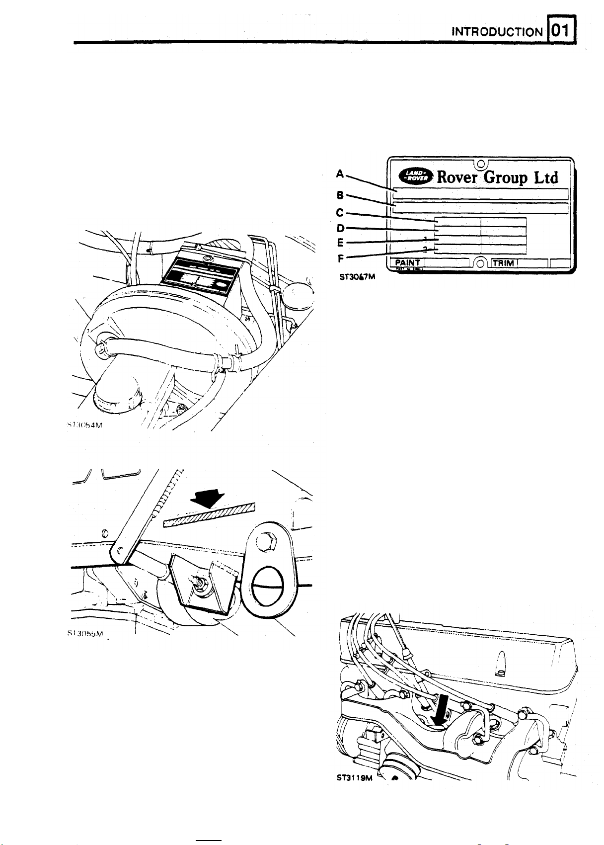
LOCATION OF VEHICLE IDENTlFlCATlON AND UNIT NUMBERS
VEHICLE IDENTtFlCATlON NUMBER (VIN)
The Vehicle Identification Number and the
recommended maximum vehicle weights are
stamped on a plate riveted
to
the top of the brake
pedal box in the engine compartment.
The number is also stamped on the right
of the chassis forward
of
the spring mounting turret.
Always quote this number when writing
-
hand side
to
Land
Rover.
Key to Vehicle Identification Number Plate
A
Type approval
B
VIN (minimum
Maximum permitted laden weight for vehicle
C
Maximum vehicle and trailer weight
D
E
Maximum road weight - front axle
F
Maximum road weight - rear axle
of
17
digits)
The Vehicle Identification Number identifies the
manufacturer, model range, wheel base, body type,
engine, steering, transmission, model name and
place of manufacture. The following example shows
the coding process.
SAL
LD
H
M
V
7
=
Land Rover.
=
Land Rover Ninety and One Ten.
=
One Ten inch.
=
4
door
station wagon. A = pick-up hood cab
truck hard
=
V8.
C
=
B
=
2.5
Turbo Diesel.
=
RH
stg. with 5 speed gearbox.
V = Ninety inch.
top.
2.5
Diesel. D
=
2.5
Petrol.
8
=
LH
with 5 speed gearbox.
A
=
Ninety.
B
=
One Ten. E = Ninety,
One Ten 1988 model year.
A
=
Solihull build.
F
=
Assembled locally
from kit.
The
last
six
digits
identify
build sequence
number.
The
V8
engine serial number
is
stamped on a cast
pad on the cylinder block between numbers
cylinders.
stg.
3
and
5
REISSUED:
FEB
1993
7
Page 18

MAIN GEARBOX LT77 FRONT AXLE
Stamped on a pad on the right-hand side
gearbox immediately below the
TRANSFER GEARBOX
LT230T
oil
filler level
of
plug.
the
Stamped on top
REAR AXLE
Stamped
on
top
illustrated)
on
of
left-hand axle tube for
.
of
the left-hand axle tube.
rear
of
left-hand axle tube on
90
models
110,
(110
and
axle
8
REISSUED:
FEB
1993
Page 19

GENERAL SPECIFICATION DATA
ENGINE
Type
Number
Bore
Stroke
Capacity
Valve operation
Compression ratio
Maximum power
Crankshaft
Main journal diameter
Minimum regrind diameter
Crankpin journal diameter
Minimum regrind diameter
Crankshaft end thrust/(end float)
Main bearings
Number and type
Material
Diametrical clearance
Undersize bearing
3.9
V8
.....................................................................................
of
cylinders
.............................................................
.....................................................................................
...................................................................................
...............................................................................
....................................................................
................................................................
...................................................................
..........................................................
...................................................
....................................................
...................................................
.........................................
.................................................................
................................................................................
..........................................................
shells
......................................................
V8
Eight,
two
banks
of
four
94.00 mm
71.12 mm
3950 cc
Overhead by push-rod
9.35:1
134kW
58.409-58.422 mm
57.393-57.406 mm
50.800-50.812
49.784-49.797 mm
Taken on thrust washers
0.10
5,
Lead-indium
0.010-0.048 mm
0.254
at
4750 rev/min
mm
-
0.20 mm
Vandervell shells
mm,
0.508
mm
of
centre main bearing
Connecting rods
Type
.....................................................................................
Length between centres
Big-end bearings
Type and material
Diametrical clearance
-
float crankpin
End
Undersize bearing shells
Piston pins
Length
Diameter
Fit
Clearance
..................................................................................
..............................................................................
-
in connecting rod
in
piston
.......................................................
.................................................................
..........................................................
................................................................
......................................................
............................................................
.......................................................
Horizontally split big-end, plain small-end
143.81-143.71 mm
Vandervell
0.015-0.055 mm
0.15-0.36mm
0.254 mm,
72.67-72.79 mm
22.215-22.220 mm
Press
0.002-0.007 mm
fit
VP
lead-indium
0.508
mm
REISSUED:
FEB
1993
1
Page 20

GENERAL SPECIFICATION DATA
Pistons
Clearance in bore, measured at bottom
of skirt at right angles to piston pin
Piston rings
......................................
0.018-0.041 mm
Number of compression rings
Number
No 1 compression ring
No 2 compression ring
Width of compression rings
Compression ring gap
Oil control ring type
Oil
Oil control ring rail gap
Camshaft
Location
Bearings
Number of bearings
Drive
Tappets
Valves
Length:
Seat angle:
Head diameter:
Stem diameter:
Stem
Valve
Valve spring length fitted
of
control rings
.........................................................
.........................................................
..........................................................
..............................................................
control ring width
............................................................
.........................................................
...............................................................................
...............................................................................
.............................................................
.....................................................................................
...........................................................................
to
guide clearance:
lift
(Inlet
and Exhaust)
..............................................
........................................................
..................................................
...................................
Inlet
Exhaust
Inlet
Exhaust
Inlet
Exhaust
Inlet
Exhaust
Inlet
Exhaust
.............................
...................................
.............................
...................................
.............................
...................................
.............................
...................................
.............................
..............;.................................
......................................................
2
1
Molybdenum barrel faced
Tapered and marked ‘T' or ‘TOP'
1.478-1.49 mm
0.40-0.65 mm
Hepworth and Grandage
3.0
mm
0.38-1.40 mm
Central
Non serviceable
5
Chain 9.52 mm pitch x 54 pitches.
Hydraulic-self-adjusting
116.59-117.35 mm
116.59-117.35 mm
45°
to
45 1/2°
45°
to 45 112°
39.75-40.00 mm
34.226-34.480 mm
8.664-8.679 mm
8.651-8.666 mm
0.025-0.066 mm
0.038-0.078 mm
9.49 mm
40.4
mm at pressure
of
29.5
kg
Lubrication
System type............................................................................ Wet sump, pressure fed
Oil pump
Oil pressure
Oil filter
Oil filter-external
2
type
........................................................................
........................................................................
-
internal .................................................................... Wire screen, pump intake filter
...................................................................
REISSUED:
Gear
2.11 to 2.81 kg/cm² (30 to
with engine warm
Full flow, self-contained cartridge
FEB
1993
40
p.s.i) at 2400 rev/min
in
Page 21

TRANSMISSION
Main gearbox
-
Type
Main gearbox ratios
Transfer gearbox
Type
Overall ratio
Manual
.............................................................
.....................................................................................
..........................................................................
GENERAL
LT77
5-speed helical constant mesh, with
synchromesh on all forward gears
Fifth (Cruising gear)
Fourth 1.000:1
Third 1.436:1
Second 2.180:1
First
Reverse 3.718:1
LT230T. Two-speed reduction on main gearbox
output. Front and rear drive permanently engaged via
a lockable differential.
Fifth (Cruising gear) 3.9663:1 9.3401:1
Fourth 4.9893:1 11.7471:1
Third 7.1656:1 16.8712:1
Second
First 18.2094:1
Reverse 18.9497:1 44.9233:1
SPECIFICATION DATA
0.795:1
3.650:1
In
high
transfer transfer
10.8786:1
In low
25.6134:1
42.3734:1
Rear Axle - One Ten only
Type
Ratio ....................................................................................
Track .................................................................................... 1485,90 mm
Rear Axle - Ninety only
Type
Ratio
Track
Front
Type
Ratio
Track
PROPELLER
Type: Front and rear
SUSPENSION
Type
Front .................................................................................. Transverse location of axle by Panhard rod. and fore
Rear ..................................................................................... Fore and aft movement inhibited by two trailing links
.....................................................................................
.....................................................................................
.....................................................................................
....................................................................................
Axle
.............................................................................................................
..................................................
....................................................................................
SHAFTS
.......................................................
.....................................................................................
Salisbury 8HA
3.538:1
Land Rover spiral bevel
3.538:1
1485,90 mm
Land Rover spiral bevel
3.538:1
1485,90 mm
Single Hookes universal needle roller joints.
Coil springs controlled by telescopic dampers
and rear
and aft location by two radius arms
Lateral location of axle by a centrally positioned 'A'
bracket bolted at the apex to a ball joint mounting.
Defender 110 has a levelling unit is positioned
between the ball joint and upper cross member
front
REVISED:
OCT
1993
3
Page 22

GENERAL SPECIFICATION DATA
BRAKES
System
Foot
Front
Rear
Rear drum brakes
.................................................................................
brake
Type
..........................................................................
Disc Diameter.......................................................
of
Number
Total lining area
Lining material
disc
Type
Disc diameter
Number
Lining material .................................................. Don 230 (Asbestos) or Ferodo 3440
Type
Drum diameter
Total lining area
Brake drum width
Lining material
pistons per wheel
......................................
..................................................................
brakes
.....................................................................
................................................................
of
pistons per wheel
..............................................................................
..............................................................
............................................................
..........................................................
..............................................................
...................................
........................................
Direct acting servo assisted dual braking system
Girting tandem master cylinder and G valve
Lockheed Disc
300
mm
4
(Asbestos) or Ferodo 3440 (Asbestos free)
Lockheed
290
mm
D
I
S
C
2
Girting single cylinder drum brake
280
mm
493
cm²
63.9
mm
Ferodo
2629
with
Handbrake
Type
Drum diameter
Lining material
...........................................................................
.....................................................................
......................................................................
Transmission drum brake cable operated
254
Don
STEERING
Power
Make/type
Ratio
Steering wheel turns, lock-to-lock
Steering
Make/type
Operating pressure - straight ahead position - at idle
Full lock (left
Full lock (left
Steering geometry
Steering
Toe
Toe
Camber
Castor angle ................................................................... 3°
Swivel pin inclination static
Steering damper
Steering column
steering
box
............................................................................
.............................................................:.......................
...................................
pump
............................................................................
..........
or
right) at idle
or right)
wheel
diameter
-
out measurement
-
out included angle
angle
..................................................................
..................................................................
type
1000
.............................,...................
rev/min
......................................
......................................................
........................................................
.....................................................
...........................................
...............................................
Adwest Varamatic - worm and roller box
Variable: straight ahead
3.75
Hoboum-Eaton series 200
7 kgf/cm² (100 p.s.i.) maximum
28
70-77 kgf/cm² (1000-1100 p.s.i.)
420mm
0
0° to 0° 16'
0° Check with vehicle in static
7°
Double acting
housing
Collapsible coupling
mm
269
kgf/cm²
to
2.0
mm
(400
p.s.i.) minimum
fitted
between drag link and pinion
19.3:1
on lock
unladen condition. that is.
vehicle with water.
oil and five gallons of fuel
Rock the vehicle up and
down at the front to allow
it to take up a static
position
17.2:1
4
REVISED:
OCT
1993
Page 23

GENERAL SPECIFICATlON
DATA
ELECTRICAL
System
Battery
Type:
Alternator
Type
Maximum
Rotor
Stator
New brush length
Renew brush at
Brush spring pressure
Regulator controlled voltage
Starter motor
Type
Brush spring tension
Brush minimum length
............................................................................................
Lucas
Chloride
Lucas - cold climate 13 plate
Chloride
.....................................................................................
-
winding resistance
-
winding resistance per phase
.....................................................................................
EQUIPMENT
-
standard 9 plate
-
standard 9 plate
-
cold climate 13 plate
D.C.
output at 6000 rev/min
...............................................
...........................................
....................................
................................
...................................................
..................................
.................................................................
....................................................................
..........................................................
................................................
............................................................
.........................................................
12 volt, negative ground
B.B.M.S. No.371
B.B.M.S.
B.B.M.S. No.389 Designation
B.B.M.S. No.3693
Magnetti Marelli A127-85
85
2.6 ohms at 2O°C ± 5%
0.092 ohms at 20°C ± 5%
20
10 mm
1.3 - 2.7 N
13.6 - 14.4 volts measured across battery
Magnetti Marelli M78R pre-engaged
1020 gms
9,5 mm
No.2911
amps
mm
Designation
90/84/90
15/120/92
Distributor & MFI system
Wiper
Type
Armature end-float
Minimum brush length
Fuses
Type
motor
.....................................................................................
...............................................................
.....................................................................................
..................................................
..........................................................
See
‘ENGINE TUNING
Lucas
14W uprated two
0,1 - 0,20 mm
4,8 mm
Cartridge fuses, located
panel, which protect the electrical components.
A complete list of circuits protected is given in
Electrical Section.
A second fuse box located in the engine compartment
next to the brake servo contains fuses to protect the
vehicle harness. For fuse values refer to the Electrical
Section.
DATA'
-
speed
in
a
box below the facia
REVISED:
OCT
1993
5
Page 24

GENERAL
Coil
Make/type
Distributor
Make/type
Firing angles .................................................................
Application
Pick
(Pick-up Iimb/reluctor tooth)
Pick-up winding resistance
Horns
Make/type
........................................................
............................................................................
...........................................................................
up air gap adjustment
............................................................................
SPECIFICATION
DATA
.................................................
..................................................
Bosch
0221 122 392
Lucas
35
DLM8
0°-45°-90° (every 45°) ± 1°
12V
Negative ground
0.20 mm to
2k
to
Klamix
0.35
5k ohms
(Mixo)
mm
TR99
Ignition
Make/type
Spark plugs
Make/type
REPLACEMENT BULBS AND UNITS
Headlamps
Front side lamps
Side marker lamps
Stop/tail lamps
High mounted stop light
Flasher lamps
Number plate lamp
Reverse lamp
Interior lamp
Warning lights
Instrument illumination
Hazard switch warning light
Heated rear Screen switch illumination
Heated front screen switch
Heated front Screen warning light
Cigar light illumination
module
............................................................................
............................................................................
...........................................................................
..................................................................
...............................................................
.....................................................................
.......................................................
......................................................................
...............................................................
.......................................................................
.........................................................................
......................................................................
.........................................................
.................................................
illumination
........................................
..........................................................
................................
...............................
Lucas 9EM amplifier module, distributor mounted
Champion RN9YC
60/55
W
halogen sealed beam
12V 5W
12V
3W
12V 21/5W
12V/5W
12V
21W
12V
4W
12V
21W
12V
21
W
12V
1.2W
12V 2W
12V 1.2W
12V
12V 1.2W
12V
12V 1.2W
1.2W
1.2W
(red)
(green)
(green)
(amber)
6
RE-ISSUED: FEB
1993
Page 25

GENERAL
SPECIFICATION DATA
VEHICLE DIMENSIONS
Overall length
Overall width
...............................................................
........................................................................
110
..................................................................
Wheelbase
Track: front and rear
Ground clearance: under differential
Rear opening height (interior)
VEHICLE
Overall length
Overall width
Overall height
Wheelbase
Track: front and rear
Ground clearance: under differential
Tailgate aperture width
Tailgate height
Interior width
Width between wheelboxes
VEHICLE WEIGHTS AND PAYLOAD
..........................................................................
............................................................
....................................
..............................................
DIMENSIONS
90
.......................................................................
........................................................................
.......................................................................
...........................................................................
............................................................
....................................
........................................................
.....................................................................
........................................................................
.................................................
1790mm
2035mm
2794mm
1485,90mm
215mm
1205mm
4072mm
1790mm
2035mm
2360mm
1485,90mm
229mm
864mm
1300mm
1450mm
925mm
When loading a vehicle to its maximum (Gross Vehicle Weight), consideration must be taken
kerb weight and the distribution
maximum values. It
that neither maximum axle loads nor
NOTE:
is
the customer's responsibility
CURB WEIGHT
of
the payload to ensure that axle loadings do not exceed the permitted
to
limit the vehicle's payload in an appropriate manner such
Gross
Vehicle Weight are exceeded.
equals the minimum unladen vehicle weight plus full fuel tank.
of
the
vehicle
GROSS
payload equipment and towing attachment load (where applicable)
GROSS
loadings which allow for the fitting
respective maximums
be exceeded.
VEHICLE WEIGHT
VEHICLE WEIGHT CONDITION
MUST BE
equals the maximum all up weight, with the driver, passengers.
of
optional equipment. The loading of
AVOIDED,
REVISED: OCT
-
the maximum axle weights shown
as the overall maximum vehicle weight
1993
both
are
individual
axles
up
to
would
axle
their
then
7
Page 26

GENERAL SPECIFICATION DATA
WHEELS
DEFENDER
AND
90
TIRES
Wheels
7.0
X
7J
16
X
16 X 33
Steel
Alloy
Tires
BF
Type and size
DEFENDER
110
Goodrich LJ265/R16 Mud Terrain
Wheels
x
Steel 139,70mm
406,40mm
Tires
Type and size 750X 12,8m (tubed)
TIRE
PRESSURES
WARNING: Tire pressures must
If
at running temperature.
the vehicle has been parked
be
checked with the tires cold, as the pressure is about 0,21 bar higher
In
the sun
or
USE
RADIAL PLY
high ambient temperatures, Do not
reduce the tire pressures, move the vehicle into the shade and wait for the tires
the pressures.
Radial
to
cool before checking
Ply
TIRES
ONLY
General Notes
Emergency soft pressures should
Max
speed
40
Towing When vehicle is
applicable
WARNING:
Do not
they are designed
proper operation
of
size recommended
doubt,
8
consult
Land
only
be
used
in
extreme conditions where extra flotation
km/h
(25
mph). Return pressures
used
for
replace
for
the road wheels with any type other than genuine Land Rover wheels,
multi-purpose on and
towing
off
to
normal immediately firm ground is regained.
the reduced rear tire pressures for extra ride comfort are not
road use and have very important relationships with the
the suspension system and vehicle handling. Replacement tires should
in
this manual and all be the same make, ply rating and tread pattern.
Rover
Service department
REVISED:
for
advice.
OCT
1993
is
required
be
If
in
of
as
the
any
Page 27

ENGINE
TUNING
DATA
ENGINE
Type
Firing order
Cylinder Numbers
Left bank
Right bank
No
Timing marks
Spark plugs
Gap
Coil
Make/type
Compression ratio
Fuel injection system
Valve Timing Inlet Exhaust
Opens
Closes
Duration
Valve peak 104° ATDC 114° BTDC
3.9
V8
.....................................................................................
.........................................................................
..............................................................................
............................................................................
1
Cylinder location
.......................................................
......................................................................
......................................................................................
............................................................................
.............................................................
........................................................
..................................................................................
..................................................................................
...............................................................................
...........................................................................
3.9 Litre V8
1-8-4-3-6-5-7-2
1-3-5-7
2-4-6-8
Pulley end
On crankshaft vibration damper
0.84-0.96mm
Bosch 0-221-122-392, (ETC 6574)
9.35:1
Lucas 14 CUX Hot-wire air
electronically controlled
32° BTDC
73° ABDC
285° 285°
of
left bank
flow
sensor system
70° BBDC
35° ATDC
Idle speed - controlled by
Base idle speed
Ignition Timing - dynamic at idle speed,
vacuum disconnected
Exhaust gas
CO content at idle
..................................................................
................................................................
MFI
system
.............................
.......................................................
700 ± 25 rev/min
See setting procedure - 525 ± 25 rev/min.
5° BTDC ±
0%
to
1
°
0.05% max.
REISSUED:
FEB
1993
1
Page 28

ENGINE Nm
Alternator mounting bracket to cylinder
Alternator
Alternator to adjusting link
Chainwheel to camshaft
Connecting rod bolt
Cylinder head:
Outer row
Centre row
Inner row
Distributor clamp nut
Exhaust manifold
Fan
Flywheel
Inlet manifold
Lifting eye
Main bearing cap bolts
Main bearing cap rear bolts
Manifold gasket clamp bolt
Oil pump cover
Oil plug
Oil
relief valve cap
Oil sump drain plug
Oil
sump
Oil
sump rear
Rocker cover to cylinder head
Rocker shaft bracket
Spark plug
Starter motor attachment
Damper
Timing cover
Viscous unit
Water pump pulley to water pump hub
Water pump timing cover
to
mounting bracket
.............................................
....................................................
.......................................................
..............................................................
.............................................................................
...........................................................................
..............................................................................
............................................................
to
cylinder heads
to
viscous unit
to
crankshaft
to
...............................................................
.........................................................
to
cylinder heads
cylinder heads
...........................................
................................................
.........................................................
.................................................
..................................................
to
timing cover
............................................
.................................................................................
................................................................
..............................................................
to
cylinder block
to
cylinder block
....................................................
.............................................
.............................................
to
cylinder head
............................................................................
.....................................................
to
crankshaft
to
to
...........................................................
cylinder
water pump hub
block
...........................................
to
cylinder block
head
......................
.....................................
..................................
..............................................
................................
..........................
40
24
24
58
51
58
92
92
21
21
30
78
51
24
72
92
17
13
28
40
45
10
18
7
37
15
44
271
27
45
10
27
TORQUE
WRENCH
SETTINGS
FUEL LINES
Connections at straight connector
Pipe connections at filter
Hose clips
Connections at vapour separator
Connections at Tee-piece
CLUTCH
Clutch cover bolts
Slave cylinder bolts
............................................................................
......................................................
....................................................
................................................................
..............................................................
.......................................
.........................................
16
16
2
16
16
27
27
REISSUED:
FEB
1993
1
Page 29

TORQUE WRENCH SETTINGS
MAIN GEARBOX (FIVE-SPEED)
Oil pump body to extension case
Clip
to
clutch release lever
Attachment plate
Attachment plate
Extension case
Pivot plate
Remote selector housing to extension case
Gear lever housing
Guide
clutch release sleeve
Slave cylinder
Front cover
5th support bracket
Plunger housing
Blanking plug extension case
Gear lever retainer
Yoke
to
selector shaft
Fixing gear lever assembly nut
Reverse pin
Clutch housing
Plug - detent spring
Oil drain plug
Oil filter plug
Plug
oil
filler - remote housing
Breather
Oil level plug
Blanking plug - reverse switch hole
Fifth gear layshaft nut
...............................................................................
to
gearcase
to
remote housing
to
gearcase
............................................................................
to
to
clutch housing
to
gearcase
..............................................................
to
remote housing
...............................................................
to
centre plate nut
to
gearbox bolt
..............................................................
........................................................................
.........................................................................
........................................................................
......................................
remote housing
.......................................................
..........................................................
..........................................................
LT77S
.........................................
..................................
....................................
.................................................
.................................
.................................................
...........................................
.....................................
..............................................
............................................
............................................
............................................
..............................................
.....................................
........................
Nm
9
9
25
25
25
25
25
25
25
25
25
9
9
25
44
25
72
25
51
72
30
9
30
24
217
2
REISSUED:
FEB
c
1993
Page 30

TORQUE
WRENCH
SETTINGS
TRANSFER
Fixings securing mounting brackets
Pinch bolt operating arm
Gate plate
Bearing housing
Speedometer cable retainer
Speedometer housing
Locating plate to gear change
Bottom
Front output housing to transfer
Front output housing
Cross shaft housing to front output housing
Gear change
Gear change
Cross shaft to high/low lever
Pivot shaft to link arm
Connecting rod
Anti-rotation plate intermediate shaft
Front
output
Pivot
bracket
Finger housing
Mainshaft bearing housing to transfer case
Brake drum to coupling flange
Gearbox to transfer case
End cover bearing housing to transfer case
Speedometer housing
Selector finger
Selector fork high/low
Transmission
Gearbox
Transfer case assembly
Oil drain plug
Detent plug
Differential casings
Front and rear out flange
Differential case rear
Oil filler and level plug transfer
Transfer breather
Inner shaft stake nut
GEARBOX
LT230T Nm
to
gearbox
......................................................
to
grommet plate
to
transfer case
................................................
.........................................
.................................................
..........................................................
..............................................
cover to transfer
.......................................................
...........................................
to
transfer
...........................................
........................................................................
........................................................................
................................................
...........................................................
.....................................................................
...................................
housing cover
to
extension housing
to
front output housing
..................................................
......................................
................................
.............................................
.....................................................
to
to
cross shaft (high/low)
brake
to
transfer case
transfer
to
shaft
to
speedometer housing
.........................................
...............................
...................................................
.....................................................
.......................................................
........................................................................
...........................................................................
...............................................................
.....................................................
............................................................
.............................................
.................................................................
............................................................
...................
........................
.........................
........................
................
90
9
9
9
9
See note
6
25
25
25
25
25
25
25
25
25
25
25
25
25
25
25
45
45
45
25
25
72
45
See
note
30
Plug
to
be coated with Hylomar and peened Screw
plug fully in (spring solid) then turn two complete turns
.
back
60
162
.
72
30
9
135
N0TE:
sufficient torque to wind them
torque must not exceed the maximum figure quoted
for the associated nut on final assembly
FRONT AXLE
Hub driving member
Stub axle
Upper swivel pin to swivel pin housing
Lower swivel pin
Oil
Swivel
Pinion housing
Crown wheel
Differential bearing cap to pinion housing
Universal Joint flange to propeller shaft
Mudshield
Bevel pinion nut
Studs
to
be assembled
to
hub
..................................................
to
swivel pin housing
to
swivel pin housing........................
seal retainer
bearing housing to axle case
to
to
swivel pin housing
to
axle case
to
differential case
swivel pin housing
.................................................
...................................................................
into
casings with
fully
home, but this
.
............................................
................................
.............................
....................................
..........................................
............................
...............................
..........................................
REISSUED:
65
65
65
25
9
72
41
58
90
47
9
129
FEB
1993
3
Page 31

TORQUE
WRENCH
SETTINGS
REAR AXLE AND FINAL DRIVE
Crown wheel to differential case
Rear cover to axle case
Ball joint mounting bracket to axle case
Universal Joint flange
Drum to hub
Rear brake assembly and stub axle rear to axle
Hub driving member to hub
PROPELLER SHAFTS
Coupling flange bolts
REAR SUSPENSION
Bottom link to chassis nut
Bottom link to mounting rubber
Top link bracket to chassis
Bump stop rubber bracket nuts
Shock absorber bracket to chassis
Shock absorber upper attachment to bracket
Anti
roll bar bush to chassis nuts
Upper link ball joint to axle castle nut
Anti roll bar ball joint castle nut
Shock absorber lower attachment nuts
.........................................................................
.......................................................
to
propeller shaft
...........................................................
..........................................
...............................
...............................
..................................................
....................................................
............................................
...................................................
............................................
......................................
......................
.........................................
...................................
............................................
................................
Nm
160
24
133
47
18
..................
65
65
46
176
64
47
32
64
82
24
40
75
176
STEERING AND FRONT SUSPENSION
Tie bar to mounting arm nut
Mounting arm to chassis nuts
Tie bar to steering box nuts
Panhard rod to mounting arm nut
Panhard rod
Panhard rod mounting bracket to chassis bolts
Drop arm to drag link castle nut
Steering damper to drag link nut
Drop arm to steering box nut
Radius arm to axle nuts
Steering box to chassis nuts
Radius arms to chassis nuts
Track rod clamp bolt nuts
Drag link clamp bolt nuts
Steering wheel retaining nut
Road wheel nuts
Ball joint nuts
Collapsible coupling nuts
to
anchor bracket nut
..................................................................
........................................................................
.................................................
..............................................
.................................................
........................................
......................................
...........................................
..........................................
...............................................
.......................................................
.............................................
................................................
.....................................................
......................................................
................................................
.....................................................
...................
81
81
176
81
88
88
123
81
50
176
176
176
14
14
30
108
41
25
4
REISSUED:
FEB
1993
Page 32

TORQUE
WRENCH
SETTINGS
POWER ASSISTED STEERING
Mounting bracket to front cover
Mounting bracket
Mounting plate
Pulley to P A S pump
P.A.S pump
P.A.S box
P.A.S box 14 mm thread
P.A.S pump union
P.A.S pump Jubilee clips
BRAKES
Brake disc to hub
Brake caliper to swivel housing
Brake pipe connections
Servo. primary port
Servo. secondary port
Jump hose
Wheel cylinders to back plate
'G'
valve
'G'
valve
Master cylinder
Servo to bulkhead nuts
16
...............................................................................
to
to
cylinder block
to
mounting bracket
...........................................................
to
mounting bracket
mm thread
................................................................
.................................................................
..............................................................
..........................................................
-
female
bracket
.............................................................
..............................................................
to
servo nuts
......................................................
......................................................
.....................................................
to:
..............................................
...............................................
........................................................
...........................................
.......................................
.....................................
.........................................
............................................
Nm
25
25
25
9
25
20
15
20
3
72
100
13
13
15
11
10
13
14
14
ELECTRICAL EQUIPMENT
Alternator:
Shaft nut
Through bolts
Rectifier bolts
Starter motor to engine bolts
Starter motor:
Through bolts
Solenoid fixing stud nut
Solenoid upper terminal nut
Reverse light switch
Lucas
Pick up bearing plate support pillars
Pick up barrel nuts
AIR
Adaptor plate
Compressor mounting bracket
Mounting plates
Compressor to mounting bracket
Adjusting link to mounting bracket & compressor
Belt damper
Pulley
35
CONDITIONING
to
.......................................................................
................................................................
................................................................
................................................
................................................................
.................................................
..........................................
.............................................................
DM8 Electronic ignition distributor
....................................
...............................................................
to
front cover
to
compressor
..................................................
to
adaptor plate
............................................
.........................................
to
front cover plate
Torsional Vibration damper
...........................................
...................................
...................
................
60
5
3,5
44
10,8
6
4
24
1,2
1,2
45
45
25
45
45
36
25
REISSUED: FEB
1993
5
Page 33

GENERAL FITTING INSTRUCTIONS
PRECAUTIONS AGAINST DAMAGE PREPARATION
1.
Always fit covers
commencing work in engine compartment. surrounding areas as thoroughly as possible.
2.
Cover seats and carpets, wear clean overalls
and wash hands or wear gloves before component removal, using greaseproof paper
working inside car.
3.
Avoid spilling hydraulic fluid or battery acid on
paint work. Wash
this occurs. Use Polythene sheets in boot
protect carpets.
4.
Always use a recommended Service
a satisfactory equivalent, where specified.
5. Protect
replacing nuts or fitting plastic caps. in a suitable container; use a separate
temporarily
SAFETY PRECAUTIONS - (See
-
Poisonous Substances)
1.
Whenever possible use a ramp or pit when agent; check that agent is' suitable for all
working beneath vehicle, in preference
jacking. Chock wheels as well as applying
hand brake. labels, containers and locking wire before
2.
Never rely on a jack alone
Use axle stands or blocks carefully placed at
jacking points
3.
Ensure that a suitable form
is conveniently located.
4.
Check that any lifting equipment used has dismantling components, particularly when
adequate capacity and is
5.
Inspect power leads of any mains electrical worked on.
equipment for damage and check that
properly earthed.
6.
Disconnect earth (grounded) terminal of
vehicle battery. and fluid passages with an air line. Ensure
7.
Do not disconnect any pipes in air that any O-rings used for sealing are correctly
conditioning refrigeration system, if fitted, replaced or renewed,
unless trained and instructed
refrigerant is used which can cause blindness replaced as dismantled. Whenever possible
if
allowed to contact eyes. use marking ink, which avoids possibilities
8.
Ensure that adequate ventilation
when volatile degreasing agents are being punch
to
used.
WARNING: Fume extraction equipment
must
be
in operation when trachloride,
methylene chloride, chloroform or
perchlorethylene are
purposes
Do not apply heat in an attempt to free stiff rebuild.
9.
nuts
protective coatings, there is a risk of damage
to electronic equipment and brake lines from that its correct replacement
stray heat. obtained.
10.
Do
around or
11.
Wear protective overalls and use barrier
creams when necessary.
.
or
fittings; as well as causing damage to
not
leave
on
work area.
to
protect wings before
off
with water immediately
exposed screw threads by
also SECTION
to
support vehicle.
provide rigid location.
of
fire extinguisher
fully
serviceable. brake, fuel or hydraulic system parts are being
to
tools,
used
equipment, spilt oil etc.,
for cleaning
1.
Before removing a component, clean
2.
Blank
and masking tape.
3.
Immediately seal fuel, oil or hydraulic lines
if
to
Tool,
or component removal, with tapered hardwood
01
to
when separated, using plastic caps or plugs,
to
4.
Close open ends of oilways, exposed by
plugs or readily visible plastic plugs.
5.
Immediately a component is removed, place
container for each component and its
associated parts.
6.
Before dismantling a component, clean
thoroughly with a recommended cleaning
materials of component.
7.
Clean bench and provide marking materials,
dismantling a component.
off
prevent
any openings exposed by
loss
of fluid and entry
DISMANTLING
1.
Observe scrupulous cleanliness when
A
particle
it
is fragment could cause a dangerous
malfunction
2.
Blow
do
so.
A
is
provided distortion or initiation of cracks, liable
3.
Mark mating parts to ensure that they are
4.
Wire together mating parts where necessary
to
prevent accidental interchange (e.g. roller
bearing components).
5.
Wire
renewed, and to parts requiring further
inspection before being passed for
reassembly; place these parts in separate
containers from those containing parts for
6.
Do not discard a part due for renewal until
after comparing it with a new part, to ensure
if
trapped
out
ail tapped holes, crevices, oilways
or
scriber are used.
labels
on to all parts which are to be
of
dirt or a cloth
in
these systems.
if
disturbed.
of
it
dirt.
has
and
if
centre
its
it
it
of
been
REISSUED:
FEB
1993
1
Page 34

GENERAL
FlTTlNG
INSTRUCTIONS
INSPECTION - GENERAL
1.
Never inspect a component for wear or
dimensional check unless
clean; a slight smear of grease can conceal
an incipient failure.
2.
When a component is to be checked
dimensionally against figures quoted for it, use
correct equipment (surface plates,
micrometers, dial gauges, etc.) in serviceable
condition. Makeshift checking equipment can
be dangerous.
3.
Reject a component
outside limits quoted, or
apparent. A part may, however, be refitted
its critical dimesnion is exactly limit size, and
is otherwise satisfactory.
4. Use plasti-guage 12
bearing surface clearances; directions for its
use, and a scale giving bearing clearances in
0,0025 mm steps are provided with it. bearings (e.g. taper roller bearings)
BALL
AND
ROLLER BEARINGS
it
is absolutely to inner ring
if
its dimensions are
if
Type PG-1
for checking
damage is
if
it
could be established that damage was
confined to
9.
When fitting bearing to shaft, apply force only
it
only.
of
bearing, and only to outer ring
when fitting into housing.
10.
In the case of grease-lubricated bearings (e.g.
hub bearings) fill space between bearing and
outer seal with recommended grade of grease
before fitting seal.
11.
Always mark components of separable
dismantling, to ensure Correct reassembly.
Never
fit
new rollers in a used cup.
in
NEVER
WITHOUT
SERVICABLE CONDITION
REPLACE
FIRST
1.
Remove all traces of lubricant from bearing replace a seal exactly when
under inspection by washing
A
BALL
ENSURING THAT
OR
ROLLER
IS
in
suitable degreaser; maintain absolute
cleanliness throughout operations.
2.
Inspect visually for markings of any form on
rolling elements, raceways, outer surface of dust excluder seals
outer
rings or inner surface of inner rings. grease duplex seals in cavity between sealing
Reject any bearings found to be marked, lips.
since any marking in these areas indicates
onset of wear. correctly
.
Holding inner race between finger and thumb
of one hand, spin outer race
and
revolves absolutely smoothly, Repeat, holding sleeve when possible to protect sealing lip
outer race and spinning inner race.
4.
Rotate outer ring gently with a reciprocating splines,
motion, while holding inner ring; feel for any plastic tube
check or obstruction to rotation, and reject damage to sealing lip.
bearing if action is
5. Lubricate bearing generously
appropriate
6. Inspect shaft and bearing housing for
to
not
perfectly smooth.
installation.
with
discolouration or other marking suggesting
i
that movement has taken place between
bearing and seatings. (This is particularly to
be
expected if related markings were found in
operation
2.)
If markings are found, use
'Loctite' in installation of replacement bearing.
7.
Ensure that shaft and housing are clean and
free from burrs before fitting bearing.
8.
If one bearing of a pair shows an imperfection
it
is
generally advisable to renew both
bearings: an exception could be made
faulty bearing had covered a low mileage, and
BEARING
IN
A
FULLY
petrol
or
check that
lubricant
if
O
I
L
SEALS
1.
Always fit new oil seals when rebuilding an
assembly. It is not physically possible to
a down.
2.
Carefully examine seal before fitting to ensure
that it is clean and undamaged.
3.
Smear sealing lips with clean grease; pack
4.
Ensure that seal spring, if provided,
5.
Place
it
and slide into position on shaft, using fitting
from damage by sharp corners, threads or
the
it
has bedded
with
grease, and heavily
is
fitted.
lip of seal towards fluid to be sealed
If
fitting sleeve is not available, use
or
adhesive tape to prevent
2
REISSUED: FEB
1993
Page 35

GENERAL FITTING INSTRUCTIONS
6.
Grease outside diameter of seal, place square
FLEXIBLE
HYDRAULIC
PIPES,
HOSES
to housing recess and press into position,
using great care and
if
possible a 'bell piece'
Before removing any brake
or
power steering
1.
to ensure that seal is not tilted. (In some hose, clean end fittings and area surrounding
cases
housing before fitting to shaft.) Never let
weight of unsupported shaft rest in seal.
it
may be preferable to fit seal to them as thoroughly as possible.
2. Obtain
appropriate blanking caps before
detaching hose end fittings,
be immediately covered
3.
Clean hose externally and blow through
to
so
that ports can
exclude dirt.
airline, Examine carefully for cracks,
separation of plies, security of end fittings and
external damage.
Reject
any hose found
faulty.
4.
When refitting hose, ensure that no
unnecessary bends are introduced, and that
hose is not twisted before
or
during tightening
of union nuts.
5.
Containers
for
hydraulic fluid must be kept
absolutely clean.
6.
Do
not store hydraulic fluid in an unsealed
7.
If
correct service tool is not available, use a contaminated
suitable drift approximately
container.
condition would be dangerous
lowering
7.
Do
0,4
mm smaller container which has previously contained
It
will
absorb water, and fluid in this
to
use due to a
of
its boiling point.
not allow hydraulic fluid
with
mineral oil, or use a
than outside diameter of seal. Use a hammer mineral oil.
VERY GENTLY on drift
suitable.
8.
Press or drift seal
is
housing
shouldered,
in
housing where no shoulder is provided. plug
if
a press is not
to
depth of housing
or
flush with face of
if
8.
Do
not re-use fluid bled from system.
9.
Always use clean brake fluid to clean
hydraulic components.
10.
Fit a blanking cap to a hydraulic union and a
to
its socket after removal
to
Ensure that the seal does not enter the ingress of dirt.
housing
in
a tilted position.
11.
Absolute cleanliness must be observed
hydraulic components at all times.
NOTE: Most cases of failure or leakage of
oil seals are due to careless fitting, and
resulting damage to both seals and sealing
surfaces. Care in fitting is essential
results are to
be
obtained.
if
good
12.
After any work on hydraulic systems, inspect
carefully for leaks underneath the vehicle
while a second operator applies maximum
pressure
to
the brakes (engine running) and
operates the steering.
with
to
be
prevent
with
JOINTS
1.
Always use correct gaskets where they are
2.
recommended. Otherwise fit joints dry.
3.
When jointing compound is used, apply in a
thin uniform film to metal surfaces; take great
care to prevent
4.
5.
6.
AND
JOINT
FACES
specified.
Use jointing compound only when
it
from entering oilways, pipes
or blind tapped holes.
Remove all traces of old jointing materials
prior to reassembly.
Do
not use a tool which
could damage joint faces.
Inspect joint faces for scratches or burrs and
or
remove with a fine file
allow swarf
or
dirt to enter tapped holes or
oil stone; do not
enclosed parts.
Blow out any pipes, channels
compressed air, renewing any O
or
crevices with
-
rings or
seals displaced by air blast.
REISSUED: FEB
1993
3
Page 36

GENERAL
FITTING
INSTRUCTIONS
METRIC
BOLT
1.
An
IS0
and larger than 6 mm
identified by either of the symbols IS0 M or
embossed or indented on top of the head.
2.
In addition
manufacture, the head is also marked with
symbols
8.8,
gives the minimum tensile strength of the bolt Metric threads and metric sizes are being introduced
material in tns of kg/sq mm.
Zinc plated IS0 metric bolts and nuts are of parts must be expected. Although standardisation
chromate passivated, a greenish
gold-bronze colour.
IDENTIFICATION
metric bolt or screw, made of
to
marks
to
indicate the strength grade e.g.
10.9,
12.9
or 14.9, where the first figure
HYDRAULIC FlTTlNGS
in
diameter can be
to
-
Metrication
steel
WARNING: Metric and Unified threaded hydraulic
parts. Although pipe connections to brake
M
system units incorporate threads of metric form,
those for power assisted steering are of UNF
identify the
type. It is vitally important that these two thread
forms are not confused, and careful study should
be made of the following notes.
into motor vehicle manufacture and some duplication
-
khaki to must in the long run be good, it would be wrong not
to give warning cf the dangers that exist while UNF
and metric threaded hydraulic parts continue
together in service. Fitting UNF pipe nuts into metric
ports and vice
experience of the change from BSF to UNF indicated
that there is no certainty in relying upon the
difference in thread size when safety is involved.
To
provide permanent identification of metric parts is
not easy but recognition has been assisted by the
following means. (Illustration
-
versa should not happen, but
A
Metric, B Unified.)
ST1035M
METRIC NUT IDENTIFlCATlON
1.
A
nut with an IS0 metric thread is marked on
one face or on one of the flats of the hexagon
with
the strength grade symbol
Some nuts with a strength 4,
marked and some have the metric symbol
on the flat opposite the strength grade
marking.
2.
A
clock face system is used as an alternative
method of indicating the strength grade. The
external chamfers or a face
marked in a position relative to the
appropriate hour mark on a clock face to
indicate the strength grade.
3.
A
dot is used to locate the 12 o’clock position
and a dash
the grade is above 12,
o’clock position.
to
indicate the strength grade.
two
8,
12 or 14.
5
or
6
are also
of
the nut is
dots identify the
M
If
12
All
1.
2. The hexagon area
3.
metric pipe nuts, hose ends, unions and
bleed screws are coloured black.
with the letter
Metric and
in shape.
’M’.
UNF
pipe nuts are slightly different
A
ST1033M
A
of
pipe nuts is indented
B
4
STt036M
ST1034M
The metric female nut is always used
flared pipe and the metric male nut is always
with a convex flared pipe.
REISSUED: FEB
1993
with
a trumpet
used
Page 37

GENERAL FITTING INSTRUCTIONS
4. All metric ports in Cylinders and calipers have
no counterbores, but unfortunately a few
cylinders with UNF threads also have no
counterbore. The situation is, all ports with
counterbores are UNF, but ports not
counterbored are most likely to be metric.
5. The coulour of the protective plugs in hydraulic
ports indicate the size and the type of the
threads but the function of the plugs is
protective and not designed as positive
identification. In production it is difficult to use
the wrong plug but human error must be mm and 3/8 in UNF pipe nuts used for 3/16 in (or
taken into account. The Plug colours and 4,751 mm) pipe. The 3/8 in UNF pipe nut or hose can
thread sizes are:
UNF
x
RED
GREEN
YELLOW
PINK
3/8 in
7/16 in
1/2 in
7/8 in
24 UNF
x
20
x
20 UNF
x
18 UNF
UNF
METRIC
BLACK
GREY
BROWN 14 x 1,5 mm
6.
Hose ends differ slightly between metric and
UNF. Gaskets are not used with metric hoses.
The UNF hose is sealed on the cylinder
caliper face by a copper gasket by the metric
hose seals against the bottom of the port and fine file and clean' thoroughly before
there is a gap between faces
cylinder.
Pipe sizes for UNF are 3/16
outside diameter. from new, as any indentation may indicate the
Metric pipe sizes are
4,75 mm pipe is exactly the same as 3/16 in pipe.
mm pipe
pipe is
Convex pipe flares are shaped differently for metric
sizes and when making pipes for metric equipment,
metric pipe flaring tools must
is
0.014 in smaller than 1/4 in pipe. 8 mm
0.002
in
10 x 1 mm
12 x 1 mm
in,
4,75
mm, 6 mm and 8 mm. onset of wear.
larger than 5/16
be
or
of
the hose and attempting to refit key.
1/4 in and 5/16 in suitable for refitting only
6
in
pipe.
used.
ST1032M
The greatest danger lies with the confusion of 10
be screwed into a 10 mm port but is very slack and
easily stripped. The thread engagement is very weak
and cannot provide an adequate seal.
The opposite condition, a 10 mm nut in a 3/8 in port,
is difficult and unlikely to cause trouble. The 10 mm
nut will screw in 1 1/2 or 2 turns and seize. It has a
crossed thread 'feel' and it is impossible to force the
nut far enough to seal the pipe. With female pipe
nuts the position is of course reversed.
The other combinations are so different that there is
no danger of confusion.
KEYS AND KEYWAYS
1.
Remove burrs from edges
2.
Clean and inspect key closely; keys are
TAB WASHERS
1.
Fit new washers in all places where they are
used. Always renew a used tab washer.
2.
Ensure that the new tab washer is
same design as that replaced.
A
B
of
keyways with a
if
indistinguishable
of
the
ST1031M
REISSUED:
SPLIT
1.
2.
3.
FEB
PINS
Fit new split pins throughout when replacing
any unit.
Always fit split pins where split pins were
originally used.
washers: there is always a good reason for
of
the use
All
split pins should be fitted as shown unless
otherwise stated.
a split pin.
1993
Do
not substitute spring
5
Page 38

GENERAL FlTTlNG INSTRUCTIONS
NUTS UNIFIED THREAD IDENTIFICATION
1.
When tightening a slotted or castellated nut
never slacken it back to insert split pin or
locking wire except in those recommended surface of the bolt head.
cases where this forms part of an adjustment.
If
difficulty
or nuts should
thickness reduced.
2.
Where self-locking nuts have been removed
is advisable
the same type.
is
experienced, alternative washers
be
selected, or washer
it
to
replace them with new ones of The component is reduced
1.
Bolts
A
circular recess is stamped in the upper
2.
Nuts
A
continuous line
of
the flats of the hexagon, parallel to the axis
of
the nut.
3.
Studs, Brake
diameter for a short length at its extremity.
of
circles is indented
Rods.
etc.
to
the core
on
one
NOTE: Where bearing pre-load is involved
nuts should be tightened in accordance
with special instructions.
LOCKING WIRE
1.
Fit new locking wire of the correct type for all
assemblies incorporating
2.
Arrange wire
tighten the bolt heads, or nuts, to which it is
fitted.
SCREW THREADS
1.
Both UNF and Metric threads to ISO
standards are used. See below for thread
identification.
2.
Damaged threads must always
Cleaning up threads with a die
the strength and closeness of fit of the
threads and is not recommended.
3.
Always ensure that replacement bolts are at
least equal
4.
Do not allow oil, grease or jointing compound
to
enter blind threaded holes.
action on screwing
split the housing.
5.
Always tighten a nut or bolt
recommended torque figure. Damaged
corroded threads can affect the torque
reading.
6.
To
check or re-tighten a bolt
specified torque figure,
of a turn, then re
7.
Always oil thread lightly before tightening to
ensure a free running thread, except in the
case of self
so
in
strength
-
tighten to the correct figure.
-
locking nuts.
it.
that its tension tends to
or
to
those replaced.
The
in
the bolt or stud could
or
first
slacken a quarter
be
discarded.
tap impairs
hydraulic
to
screw to a
the
or
1
ST1039M
3
2
6
REISSUED:
FEB
1993
Page 39

RECOMMENDED LUBRICANTS,
FLUIDS
AND CAPACITIES
RECOMMENDED LUBRICANTS
AND
FLUIDS
REISSUED:
FEB
1993
1
Page 40

RECOMMENDED LUBRICANTS, FLUIDS AND CAPACITIES
2
REISSUED:
FEB
1993
Page 41

CAPACITIES
RECOMMENDED
LUBRICANTS.
FLUIDS
AND
CAPACITIES
The following capacity figures are approximate and are provided as a guide only .
using the dipstick or level plugs as applicable
Component Litres Imperial units
Engine sump oil
Extra when refilling after fitting new filter
Main gearbox oil. five
LT230T transfer gearbox
Front differential ...................................................................................
Rear differential: Salisbury
Swivel pin housing oil (each)
Cooling system
Power steering box and reservoir fluid
.............................................................................................
-
speed
LT77S
.................................................................. 2,30
8HA
..............................................................
.....................................................................
.........................................................................
............................................................................................
...........................................................
.
.......................................................
5,10
OS6
2,20
1,70
2,30
0,35
12,80
2,90
All
oil
levels must be set
9.00
pints
1.00
pint
3.90
pints
4.00 pints
3.00
pints
4.00 pints
0.60 pint
22.50
pints
5.0
pints
REISSUED:
FEB
1993
3
Page 42

MAINTENANCE
WORKSHOP MAINTENANCE SCHEDULES
The following maintenance should be carried out by trained personnel in a fully equipped workshop. If the
vehicle is operating in a remote area where workshop facilities are not available, maintenance and repair work
should be carried out by experienced mechanics in safe conditions. Maintenance should normally be carried out
at 7,500 miles (12,000 km) intervals or six months, whichever is first, as described in the following schedules,
In severe conditions, such as deep mud or sand, or a very dusty atmosphere, the intervals should be reduced
to monthly, weekly or even daily for some items. Ask your Dealer for advice.
WARNING: DO NOT use any lubricants solvents or sealants etc, before reading any warnings and
instructions supplied with these substances, as they could be harmful if improperly used.
WARNING: Two wheel roller tests (Dynamometer) must be restricted to 5 km/hour (3 miles/hour). DO
NOT engage the differential lock or the vehicle will drive off the roller test rig because the Defender 110
is a permanent 4 wheel drive.
WARNING: Use care when draining oil from the engine, gearbox and axles, if it is hot it could cause
personal scalding.
WARNING: DO NOT work underneath the vehicle unless
it
is supported by heavy duty stands, otherwise the vehicle could move causing personal injury.
it
is
safely parked and the wheels chocked, or
REISSUED:
FEB
1993
1
Page 43

ALL
MAINTENANCE
NORTH
AMERICAN MODELS
First 1000 miles (1600km) service
Renew engine oil.
Check/top up transfer box oil.
Renew front axle oil.
Renew rear axle oil.
Renew steering swivel housing oil.
Chec/top up power steering fluid.
Check/top up transmission oil. Check operation
Check/top up clutch and brake m/c fluid level. temperature gauges, warning indicators, lamps,
Check for oil/fluid leaks from: horns and audio unit.
Suspension, dampers and self levelling unit, engine Check operation of front and rear screen
and transmission units, front and rear axles. wash/wipers.
Check brake pipes/unions for security, chafing leaks Check operation and security of rear view mirrors
and corrosion.
Check power steering system for leaks, hydraulic Check condition and security of seats, seat belt
pipes/unions for security, chafing and corrosion. mountings, belts and buckles.
Check fuel system for leaks. Check exhaust system for leaks, security and
Check fuel tank for condition and mounting bolts for damage.
tightness
Check cooling and heater systems for leaks, hoses Check tires for cuts, lumps, bulges, uneven wear,
for security and condition.
Check security and operation of park brake. Checkladjust tire pressures including spare.
Check foot brake operation.
Check condition and security of steering unit, joints Drain flywheel housing
and gaiters.
Checkladjust steering
Check front toe.
box.
only
Check positive crankcase ventilation system for leaks
and hoses for security and condition.
Check operation of throttle mechanical linkage.
Check ignition wiring and
fraying.
Checkladjust all drive belts.
of
and for cracks and crazing.
Check tires comply with manufacturer’s specification.
tread depth and road wheels for damage.
Check/tighten road wheel retaining nuts.
HT
leads for security and
all instruments, fuel and
-re-
install plug.
2
REISSUED:
FEB
1993
Page 44

CALIFORNIA
MAINTENANCE
California models
-
For maintenance after
45,000
miles (72,000
km)
we recommend that the
Required Maintenance’ is carried out in addition to the ’Recommended Maintenance’ list.
if
NOTE: The next service is due in six months
you drive less than
7,500
miles (12,000 km).
U.S.A.
REISSUED: FEB 1993
3
Page 45

MAINTENANCE
4
REISSUED:
FEB
1993
Page 46

MAINTENANCE
REISSUED:
FEB
1993
5
Page 47

MAINTENANCE
Page 48

MAINTENANCE
REISSUED:
FEB
1993
7
Page 49

MAINTENANCE
It is recommended that:
At
15,000 mile
clutch fluid should
At
37,500 mile
seals and flexible hoses should be renewed, all working surfaces of the master cylinder, wheel cylinders and
caliper cylinders should be examined and renewed where necessary.
At
37,500 mile (60,000 km) intervals remove all suspension dampers, test for correct operation, refit or renew
as necessary.
At
two
year intervals or at the onset of the second winter, the cooling system should be drained, flushed and
refilled with the required water and anti
(24,000
(60,000
km) intervals or every
be
completely renewed.
km) intervals or every 3 years, which ever is the sooner, all hydraulic brake and fluid,
18
months, whichever is the sooner, the hydraulic brake and
-
freeze solution.
The battery electrolyte level should be checked and topped up
once a year in tropical and sub
once every three years in temperate climates.
-
tropical climates
if
required
NOTE: Climatic and operating conditions affect maintenance intervals to a large extent: in many cases,
therefore, the determination
advice from an Authorised Dealer but the recommendations
of
such intervals must
be
left to the good judgement of the owner or
will
serve as a firm basis for maintenance
work.
Vehicles operating under arduous conditions will require more frequent servicing, therefore, at a minimum, the
Maintenance intervals should be reduced by half.
For low mileage vehicles it is recommended that the maintenance is carried out at
The owner need not perform recommended maintenance
manufacturer recall liability.
in
order
to
maintain the emission warranty or
6
months intervals.
SPECIAL OPERATING CONDITIONS
When the vehicle is operated
be
attention should
paid
in
extremely arduous conditions
to
all servicing requirements.
or
on dusty, wet or muddy terrain, more frequent
ADDITIONAL DAILY OR WEEKLY ATTENTION DEPENDING ON OPERATING CONDITIONS:
to
Check/top-up transfer box
Check steering rubber boots for security and condition. Renew
Check brake fluid level: consult your Dealer
Clean brake discs and calipers.
Lubricate front and rear propeller shaft grease points and front sliding joint. Under tropical or severe conditions,
particularly where sand
of abrasive material.
Every week and every maintenance inspection check tyre pressures and inspect tyre treads and side walls.
Under arduous cross
the extent of a daily check.
oil.
if
damaged.
if
any fluid loss
is
encountered, the sliding joints must be lubricated very frequently
-
country conditions the tyre pressures should
is
suspected.
be
checked much more frequently, even
to
prevent ingress
to
MONTHLY
Renew gearbox oil.
Renew transfer box oil.
6
Check air cleaner element and renew every
months or as necessary.
8
REISSUED: FEB
1993
Page 50

MAINTENANCE
5.
LUBRlCATlON
This first part of the maintenance section covers
renewal of lubricating oils for the major units of the correct grade from a sealed container
vehicle and other components that require high mark on the dipstick and firmly replace
lubrication, as detailed in the 'MAINTENANCE the filler cap. Reconnect the battery.
SCHEDULES'
capacities and recommended lubricants.
Vehicles operating under severe conditions of dust,
sand, mud and water should have the oils changed
and lubrication carried out at more frequent intervals
than that recommended in the maintenance
schedules.
Draining of used oil should take place after a run
when the oil is warm. Always clean the drain and
-
level plugs before removing. In the interests of spanner as necessary.
filler
safety disconnect the vehicle battery
engine being started and the vehicle moved washer of the new filter, and half
inadvertently, while oil changing is taking place. oil. Then screw the filter on clockwise until the
Allow as much time as possible for the oil to drain rubber sealing ring touches the machined
completely except where blown sand
enter the drain holes.
refit the drain plugs immediately the main bulk of oil
has drained. filter. Stop the engine, allow the oil
Where possible, always refill with oil of the make back into the sump for a few minutes, then
and specification recommended in the lubrication check the oil level again and top up
charts and from sealed containers.
.
Refer to 'SECTION 09' for
to
prevent the
or
dirt can face, then tighten a further half turn by hand
In
these conditions clean and only. Do not overtighten.
removed whilst the sump is empty, otherwise the
Clean the outside of the oil filler cap, remove
it
from the rocker cover and clean the inside.
6.
Pour in the correct quantity of new oil of the
to
the
RENEW OIL FILTER
CAUTION: The engine oil filter must not be
oil pump may have to be primed.
1.
Place an oil tray under the engine.
2.
Unscrew the filter anti-clockwise, using a strap
3.
Smear a little clean engine oil on the rubber
fill
with fresh
4. Run the engine and check for leaks from the
to
run
necessary.
if
WARNING: See ENGINE OILS under POISONOUS
-
SUBSTANCES
RENEW ENGINE OIL
Drain and refill engine
1.
Drive vehicle to level ground.
2.
Run the engine to warm the oil; switch
ignition and disconnect the battery for safety.
3.
Place an oil tray under the drain plug.
4. Remove the drain plug in the bottom
sump. Allow oil
replace the plug and tighten to the correct
torque.
SECTION 01. INTRODUCTION.
off
of
to
drain away completely and
the
the
REISSUED: FEB 1993
9
Page 51

MAINTENANCE
RENEW MAIN AND TRANSFER GEARBOX OILS DRAIN AND RENEW LT230T TRANSFER
GEARBOX OIL
DRAIN AND REFILL LT77S MAIN GEARBOX
1.
1.
Drive the vehicle
suitable container under the gearbox
the old oil.
2.
Remove the gearbox and extension case drain.
drain plugs and allow the oil
completely. Wash the extension case filter in
kerosene and refit
washers, if necessary, and tighten
correct torque.
to
level ground and place a container under the gearbox
to
catch oil.
2.
to
drain necessary, and tighten
3.
the
plugs using new approximate quantity
to
the until
Drive the vehicle
Remove the drain plug and allow the oil
Fit
the plug using a new washer,
Remove the filler-level plug and inject the
it
begins
level plug and tighten only to the correct
torque, do not overtighten, wipe away any
surplus oil.
to
level ground and place a
to
to
the correct torque.
of
the recommended oil
to
run from the plug hole.
catch the old
to
Fit
the
if
ST3084M
3.
Remove the oil filler-level plug and inject the
approximate quantity of new oil of the correct
make and grade until it begins to run out of
-
the filler
the correct torque. Since the plug has a
tapered thread it must not
Wipe away any surplus oil.
level hole. Fit the plug and tighten to
be
overtightened.
ST1070M
10
REISSUED: FEB
1993
Page 52

MAINTENANCE
RENEW SWIVEL PIN HOUSING OIL RENEW FRONT AND
1.
1.
Drive the vehicle to level ground and place a
Drive the vehicle to level ground and place
container under each swivel housing to catch container under the axle
the used oil.
2.
Remove the drain plug and allow the
oil
to
2.
Using a spanner with a
remove the drain plug and allow the oil
REAR
AXLE OIL
to
be drained.
13
mm
drain completely and clean and refit the plugs. drain completely. Clean and refit the drain
3.
Remove the oil filler-level plug and inject the plug.
of
recommended make and grade
oil until oil
3.
Remove the oil filler-level plug and inject new
begins to run from the level hole. Clean and oil of a recommended make and grade until
fit
the level plugs and wipe away any surplus begins
Oil.
filler-level plug and wipe away any surplus oil.
to
run from the hole. Clean and fit the
a
square drive
to
it
LUBRICATE PROPELLER SHAFTS
1.
Clean all the grease nipples on the front and
rear propshaft universal joints, and sliding
portion of the shaft.
2. Charge a low pressure hand grease gun with
grease of a recommended make and grade
and apply to the grease nipple. giving two to
three strokes of the gun only to each nipple
every 40.000 km (24,000 miles) intervals.
RE-ISSUED:
FEB
1993
11
Page 53

MAINTENANCE
GENERAL MAINTENANCE AND ADJUSTMENT
This second part of the maintenance section covers the friction pads.
adjustments and items of general maintenance as
dictated
However, only maintenance operations that are not fluid.
included in the OVERHAUL SECTlONS of the
manual appear in this section. piston back into its bore, whilst ensuring that
by
the 'MAINTENANCE SCHEDULES'
.
EXAMINE AND RENEW DISC BRAKE FRICTION
4.
Withdraw the pad retaining pins.
5.
Remove the anti-rattle springs and
6.
Clean the exposed surfaces
with new hydraulic fluid or brake cleaning
7.
Using piston clamp (18G
the displaced fluid does not overflow from the
reservoir.
of
672),
the
press each
withdraw
pistons
PADS
NOTE: Defender 90 has disc type brakes
both front and rear
with disc type brakes at
brakes
types are
rear brakes on Defender
piston calipers, The procedure for renewing
friction pads is the same for both types although
there
spring fitted, see Section 70.
Examine the friction pads for wear,
material is less than 3 mm thick
they must be renewed as described
instructions. Observe precautions
concerning asbestos:
at
the rear. Front brakes on both vehicle
fitted
may
be
a variation
axles.
with four piston calipers and the
Defender
the
front and drum type
90
are fitted with twin
in
the type of anti-rattle
or oil contaminated,
in
in
fitted
to
110
is fitted
if
the friction
the following
SECTlON 01
CAUTION: Friction pads must
sets.
1.
Loosen wheel nuts, jack-up the vehicle, lower
onto axle stands. and remove the
2.
Clean the exterior
3.
Remove the split pins, or spring clips,
the pad retaining pins.
of
me
calipers.
be
changed
in
wheels.
from
axle
8.
Smear the faces of the pistons with disc brake
lubricant, taking care not to allow any to reach
the pad lining material.
9. Insert
10. Place the anti
11. Insert the pad retaining pins and secure with
12. Apply the foot brake pedal several times to
13. Check the fluid reservoir and top up if
14 Fit the road wheels and secure with the nuts
the
new friction pads.
-
rattle springs in position.
new split pins.
locate the pads.
necessary
Jack up the vehicle to remove the axle stands
and lower me vehicle to me ground Finally.
tighten the road wheel securing nuts evenly.
to the correct torque.
12
REVISED:
OCT
1993
Page 54

MAINTENANCE
CHANGING THE HYDRAULIC BRAKE FLUID
In the service schedule it
brake fluid is renewed at
intervals or every eighteen months.
IS
recommended that the Pipes attached to the breathers on the axles
18,000
miles
(30.000
If
the following the axles to breath whilst the vehicle
km) terminate inside the engine compartment.
procedure is adopted air should not enter the mud and water.
AXLE BREATHERS
No
maintenance is required except
system. to ensure that the pipes
kinked, or split, or damaged in any other way
Proceed in the same way and order
1
bleeding the system, see
SECTION 70
clear plastic bleed tube is not available,
interpose a short length
bleed hose being used
of
glass tube into the
so
that the passage of
the fluid can be seen.
2.
Attach one end
of
the bleed hose
to
the bleed
nipple of the wheel cylinder nearest
master cylinder and immerse the
free
a glass vessel containing a small quantity
brake fluid
so
that the end
of
the tube
as
for
.
If
a
to
the
end into
of
is
prevent proper breathing.
CHECK STEERING BALL JOINTS
Ball joints are lubricated for their normal life during
manufacture and require no further lubrication. This
applies only
if
the rubber gaiter has not become
dislodged or damaged. The joints should be checked
at the specified mileage intervals but more frequently
if
the vehicle is
used
under arduous conditions.
below the fluid level.
3.
Unscrew the bleed nipple screw about
-a-
turn, enough
half
pumped out.
system
if
the screw
Air
to
allow fluid to be
could be drawn into the
is
withdrawn too far.
do
This
IS
not
become blocked,
allows
traversing
to
4
Pump-out most, but not all, of the fluid from
the reservoir by continuously depressing and
releasing the foot pedal. Do not, however,
allow the reservoir to empty completely.
5. Top-up the reservoir with new, unused fluid. of
the correct specification, from a sealed
container. See SECTION 09 .
6. Ensure that the reservoir is kept topped
-
up
and continue bleeding until the old and
discoloured fluid is dispelled and the new fluid
is seen passing through the clear bleed hose
or glass tube. Continue to bleed for two full
strokes of the pedal and then close the bleed
nipple whilst the pedal is depressed.
7 Repeat the above procedure at the remaining
wheel cylinders in turn.
-
8. Top
up the reservoir and road test the vehicle.
RE-ISSUED: FEB
1.
Check
ball joint
movement
joint assembly.
1993
for
wear
in
the joints by moving the
up
and down vigorously.
is
apparent renew the complete
If
free
‘7
Page 55

MAINTENANCE
CHECK FRONT WHEEL ALIGNMENT
Recognised front wheel alignment tracking
equipment should be used
See
SECTION 04
for wheel alignment data. Before
to
perform this check.
checking the alignment make the following checks:.
a.
The vehicle is on level ground.
b.
The vehicle
c.
The tire pressures are correct. cam.
d.
The wheels run true and are not damaged or
is
not loaded.
buckled.
e.
The track rod is not damaged
ball joints are not worn.
joints are assembled
plain and are central
in
in
or
bent and the
Also
check that the
the same angular
their housings. See
SECTION 57.
1.
Set the road wheels to the straight ahead
position and move the vehicle forward a short
distance at least
two
revolutions of the
wheels.
2.
Set up the tracking equipment to the
manufacturers instructions.
3.
Position the trammel probes on the inner face
of
the wheel, not the rims,
if
the latter are
damaged.
4.
Check the alignment as instructed
by
the
equipment manufacturers and repeat the
check on
required follow the instructions
SECTION
the
opposite wheel. If adjustment
57.
in
steering
is
ADJUST REAR BRAKES DEFENDER 110 ONLY
1.
Raise up vehicle and lower onto axle stands.
2.
Each shoe is independently set by means
of
hexagon adjuster. Check that the wheel turns
freely and turn one adjuster until the shoe
locked against the drum. Slacken off the
adjuster sufficiently
approximately
3.
Repeat the above procedure
two
for
the wheel to turn freely
serrations
on
the snail
for
the second
brake shoe and the opposite wheel.
4.
Remove the axle stands and road test the
vehicle brakes.
a
I
S
14
REVISED:
OCT
1993
Page 56

MAINTENANCE
6.
ADJUST TRANSMISSION BRAKE (Handbrake)
Set the vehicle on level ground and chock the handbrake shoes just clear the drum.
1.
wheels.
2.
Release the handbrake fully.
3.
Remove the clevis pin connecting the
handbrake lever
end.
to
the relay at the gearbox
CAUTION: DO NOT over adjust the handbrake,
the drum must be free to rotate when the
handbrake is released, otherwise serious damage
will result.
DRAIN FLYWHEEL HOUSING
4.
Turn the adjuster on the back plate clockwise
until the shoes are fully expanded against the
drum.
Fit the clevis pin, washer and a
7.
Slacken the adjuster 1 or 2 notches until
8.
Apply the handbrake gradually. The drum
should still rotate on the first ratchet and start
to
come on at the second ratchet.
1.
The flywheel housing can be completely
sealed
to
exclude mud and water under
severe wading conditions, by means of a plug
fitted in the bottom of the housing.
2.
The plug should only be fitted when the
vehicle is expected
to
muddy work.
3.
When the plug is in use
periodically and any oil allowed
before the plug is replaced.
4. When the plug
is
not in use, it must be stored
as shown.
NEW
split pin.
do wading
it
must be removed
to
or
drain
very
off
5. Adjust the outer sheath of the handbrake
cable by means
of
the
two
locknuts at the
gearbox end until the holes in the clevis on
the inner cable line up
the hole
in
the
with
relay lever
REISSUED:
ST3078M
FEB
1993
15
Page 57

MAINTENANCE
FILTERS FUEL FILTER
AIR
CLEANER ELEMENT
Removing
1.
Release the three clips and remove the inlet regarding fuel handling are strictly adhered to
tube. when carrying
2. Remove the nut and end plate.
3.
Withdraw element and discard.
Refitting precautions are taken to prevent fire and
4.
Insert the new element and reassemble the
unit in reverse order
ST3413M
to
removal.
Remove and refit
WARNING:
precautions given
WARNING:
during this operation. Ensure that all necessary
explosion.
Removing
1.
Depressurise the fuel system.
2.
The fuel filter is located on the right-hand
chassis side member forward of the fuel tank
filler neck. Access
through the right
3.
Clamp the inlet and outlet hoses
fuel spillage when disconnecting the hoses.
4. Loosen the
hoses
5.
Release the single nut and bolt securing the
filter and clamp and remove the filter.
Ensure that the fuel handling
in
Section
out
the following instructions.
The spilling of fuel
-
hand rear wheel arch.
two
fuel unions and remove the
from
the filter canister.
01
-
Introduction
is
unavoidable
to
the filter is gained
to
prevent of
AIR CLEANER
The
dump
air cleaner and
support bracket.
Checking
1.
Squeeze open the dump valve and check that
the rubber
2.
If
necessary remove the dump valve to clean
the interior.
3. Fit a new valve
condition.
DUMP
valve provides an automatic drain for the
is
VALVE
fitted in the base of the air cleaner
is
flexible and in good condition.
if
the original
is
in
a
poor
Refitting
6.
Fit a new filter observing the direction of flow
arrow on the canister.
7.
Tighten the single nut and bolt.
8. Fit the inlet and outlet hoses. Tighten the
-
unions to a torque of (27
9.
Refit the fuel pump relay. Reconnect the
battery and recode the radio.
10.
Start the engine and inspect for fuel leaks
around the hose connections.
34Nm).
16
REISSUED:
FEB
1993
Page 58

MAINTENANCE
Charcoal canister Defender
110
Remove
1.
Disconnect battery negative lead.
2.
Disconnect both purge lines.
3. Release canister from its mounting bracket.
3. Disconnect pipe.
4.
Loosen bolt and remove charcoal canister
3
Refit
4.
Reverse the removal procedure, ensuring that
is
the canister
securely located
in
its mounting
bracket and both purge lines are fitted
correctly to the canister.
WARNING:
charcoal canister or
The
use
of
compressed air to clean a
to
clear a blockage
in
the
evaporative system is highly dangerous. An
explosive
canister may
when compressed air passes
gas
present
be
ignited
in
a fully saturated
by the heat generated
through
the
canister.
Charcoal canister Defender
90
Remove
1.
Disconnect battery negative lead.
2. Pry out purge valve.
Refitting
5.
Reverse the removal procedure.
POSITIVE CRANKCASE VENTlLATION INTAKE FILTER
1.
Pry
the filter holder upwards to release
it
from
the rocker cover.
2.
Discard the sponge filter.
Fit new filter
3.
Insert a new filter into the plastic body
4.
Push the filter holder onto the
until
it
clips firmly into place
rocker
cover
REVISED: OCT 1993
17
Page 59

MAINTENANCE
CLEAN PLENUM CHAMBER VENTILATION PASSAGEWAY
7. Any remaining consolidated matter can
dislodged using a piece
pipe cleaner. Finally the passageway must
The cleaning
of
the plenum chamber ventilation again be blown out to remove any remaining
passageway can be carried out without removing the debris.
plenum chamber from the ram housing.
8.
Remove the small
crankcase ventilation hoses and check that
CAUTION:
from the passageway passing beyond the throttle
Care must
be
taken to prevent debris is free from blockages, clean as necessary
9.
Refit the ‘T’ piece and hoses, tighten the hose
valve disc. clamps securely.
WARNING:
performing this operation. Ensure that debris
not blown into the atmosphere which could
harmful to other personnel within the vicinity.
Safety glasses must
be
worn when
is
be
CLEAN POSITIVE CRANKCASE VENTILATION
BREATHER FILTER
1.
Release the hose clamp and pull the hose
the canister.
1.
Disconnect the battery negative terminal. 2. Unscrew the canister and remove
2.
Release the hose clamp and remove the hose
from the plenum chamber inlet neck.
Remove the crankcase ventilation
3.
of
the side
4.
Insert a piece of lint free cloth down the screen within the canister,
the plenum chamber.
hose from end
throttle valve bore to prevent debris passing
beyond the throttle valve.
5.
Place a cloth over the tube protruding from
of
the side
the plenum from which the
rocker cover.
3.
Remove the large
of
the canister.
4. Visually
inspect
fit a new assembly,
condition clean the screen as follows:
ventilation hose was removed to prevent
debris from the passageway being blown into
the atmosphere.
of
soft
bent
'T'
piece between the
'O'
ring from the threaded
the condition
if
of
if
in
poor condition
in an acceptable
wire
if
from the
the wire
or
be
a
it
off
18
6.
Use a compressed air
nozzle
to enable the passageway to
line
with a slim bent
cleaned out from within the throttle valve bore.
5.
Immerse the canister
solvent and allow
dissolve and loosen
within
6.
Remove canister from solvent bath and allow
to dry out in still air.
WARNING:
remove any remaining solvent or particles of
debris within the canister as this could cause fire
or personal injury.
be
Refitting the breather/filter
7
Fit a new rubber
8.
Screw the canister into the rocker
tight only.
9. Refit hose and tighten hose clamp securely
RE-ISSUED: FEB 1993
in
a
small amount
time
tor the solvent
any
engine fume debris
of
10
the canister.
Do not use a compressed air line to
'0'
ring.
cover
hand
I
Page 60

MAINTENANCE
GENERAL MAINTENANCE AND ADJUSTMENTS
OF
CHECK/ADJUST OPERATION
ALL WASHERS
AND TOP-UP RESERVOIR
1.
Check the operation
and headlamp washers.
2.
Adjust jets
or
very fine sharp implement into the jet orifice
and maneuvering
3.
Unclip the reservoir cap.
4.
Top up reservoir to
the bottom
Use a screen washer soIvent/anti-freeze in the
reservoir, this
flies and road film and protect against
freezing.
if
necessary by inserting a needle
of
the filler neck.
will
of
windscreen, tailgate
to
alter the jet direction.
within
25mm
assist in removing mud,
(1
in)
below
IGNITION
Spark plugs
1.
Take great care when fitting spark plugs not
-
to cross
damage
2. Check or replace the spark plugs as
applicable.
3.
It is important that only the correct
spark plugs are used
4. Incorrect grades
overheating and engine failure.
thread the plug, otherwise costly
to
the cylinder head
for
of
plugs may lead
will
result.
replacements.
to
type
piston
of
Fitting
RR1876E
H.T.
leads
9.
Ensure that replacement
refitted in their spacing cleats in accordance
with the correct layout illustrated.
Failure
in cross-firing between two closely fitted leads
which are consecutive in the firing order.
to observe this instruction may result
H.T.
leads are
To
remove spark plugs proceed as
5.
Disconnect the battery negative lead and
remove the leads
6. Remove the' plugs
RR2171E
7.
Set
the electrode gap to the recommended
clearance.
8. When pushing the leads onto the plugs,
ensure that the shrouds are firmly seated
the plugs.
from
and
the
washers.
follows:
spark plugs.
on
RE-ISSUED:
FEB
1993
19
Page 61

MAINTENANCE
CLEAN AND LUBRICATE V8 ENGINE ELECTRONIC DISTRIBUTOR every 40,000 km (24,000 miles)
WARNING:
involves very
personnel and wearers
devices should not be allowed near any part
the high tension circuit.
1.
Remove the distributor cap and rotor arm and
wipe inside with a nap
disturb the clear plastic insulating cover which
protects
2.
Apply three drops
rotor spindle
The electronic ignition System recirculated
high
the magnetic pick-up module.
voltages. Inexperienced The system consists
of
medical pacemaker should be examined at the same mileage intervals
-
free cloth.
of
clean engine oil to the
Do
of
not
AIR CONDITIONING SYSTEM DEFENDER 110
The air conditioning system operates in conjunction
with
the vehicle heater
or
fresh air to the vehicle interior
as the heater system:
A.
Engine mounted compressor.
B. Condenser in front
C.
A
receiver/drier in front
the condenser.
D.
Evaporator/heater unit in engine compartment
to
provide dried cooled
of
the following units which
of
the radiator.
of
and to the right
of
3.
Fit the rotor arm and distributor cap and
ensure that the
secured with the
cap is property located and
two
clips.
1.
Compressor: Check the pipe connections tor
leakage and the hoses tor swelling Check
that the drive belt is correctly tensioned
2. Condenser: Using an air line. or a water
hose, dean the exterior of the condenser
matrix. Check the pipe Connections for signs
of leakage.
20
REVISED
OCT
1993
Page 62

3.
Receiver/drier: Check the pipe connections
for signs
while the system is operating and
are present
contaminated
of
leakage. Examine the sight glass
if
bubbles
it
indicates that the system is
with
air
or
water and
will
require
CHECK BRAKE FLUID RESERVOIR
purging. reservoir.
ST3150M
MAINTENANCE
1.
Check the fluid level in the fluid reservoir
observing the level in relation to the 'MIN’
'MAX'
2.
If
outside of the filler cap and top
clean fluid from a sealed container.
fluid recommended in
cap.
marks on the side
the level
is
below the
of
the translucent
'MAX'
mark clean the
-
up with new.
'SECTION 09'.
by
Use
only
Refit the
or
4.
Evaporator: Examine the pipe connections for
leaks.
WARNING:
high
at
If any repair or servicing work
following the above inspections,
carried
The air conditioning system
is
filled
pressure with a potentially toxic material.
is
necessary
it
must
only
be
out
by a qualified air conditioning on the side
engineer who must wear protective goggles and
follow the WARNINGS and CAUTIONS given
in
SECTION 82.
CHECK
C
L
U
T
C
H
F
L
U
I
D
RESERVOIR
1.
Clean and remove the reservoir cap and
observe the fluid level in relation to the marks
of
the
reservoir.
2.
Top-up
a sealed container and
specification -
if
necessary with new, clean fluid
of
a recommended
see
'SECTION 09'.
cap.
Refit
from
the
RE-ISSUED:
ST3141M
FEB
1993
21
21
Page 63

MAINTENANCE
Do
POWER STEERING FLUID RESERVOIR
WARNING:
engine is hot because the cooling system
1.
Clean and remove the reservoir cap.
2.
Check that the fluid
the dip
stick.
I
S
Top-up
up to the lower mark on
if
necessary and refit
cap.
pressurised and personal scalding could result.
1.
When removing the filler cap, first turn
little way very gently and gauge any pressure
that may be behind
escape slowly before fully releasing the cap.
2.
With a cold engine, the coolant level should
be just to the top of the level indicator post
situated in the expansion tank below the filler
hole.
BATTERY
Check Specific Gravity
The specific gravity of the electrolyte should be
checked using a battery hydrometer. The readings
ST445
should be as follows:
Temperate climate below 26.5°C (80°F) as
commissioned for service, fully charged 1.270 to
1.290 specific gravity.
CHECK COOLING SYSTEM COOLANT
As expected during normal sewice, three-quarter
charged 1.230 to 1.250 specific gravity.
Refer to the 'COOLING SYSTEM' section for details If the specific gravity should read between 1.190 to
-
of anti-freeze and to SECTION 09 for anti
freeze 1.210, half-charged, the battery must be bench
protection quantities. charged and the electrical equipment in the car
With a cold engine, the expansion tank should be should be checked.
approximately half full. Tropical climate above 26.5°C (80°F) as
commissioned for service,
WARNING: Do not remove the filler cap when the 1.230 specific gravity.
engine is hot because the cooling system is As expected during normal sewice, three-quarter
pressurised and personal scalding could result. charge 1.170 to 1.190 specific gravity.
If the specific gravity should read between 1.130 to
1. To remove the filler cap, first turn it 1.150, half
-
clockwise a quarter of a turn and allow all
anti
pressure to escape, before turning further in
charged and the electrical equipment on the car
should be checked.
me same direction to lift it off. When replacing
the filler cap it is important that it is tightened
down fully, not just to the first stop. Failure to
tighten the filler cap properly may result in
water loss, with possible damage to the
engine through overheating.
not remove the filler cap when the
it
it.
Allow all pressure
fully
charged 1.210 to
-
charged, the battery must be bench
is
a
to
22
REVISED:
OCT
1993
Page 64

MAINTENANCE
Check and Top-Up Electrolyte Level
Wipe all dirt and moisture from the battery
1.
top. to the servo.
2.
Remove the filler cover,
sufficient distilled water
the top
Replace the filler plugs or manifold lid.
3. Avoid the use
examining the cells.
4.
In hot climates it
the battery at more frequent intervals.
5.
In very cold weather
vehicle is used immediately after topping up,
to
mixed
precaution may result in the distilled water
freezing and causing damage
of
separators.
of
will
ensure that the distilled water is thoroughly
with
the electrolyte. Neglect
If
necessary add
to
raise the level to
a naked light when
be necessary to top up
it
is essential that the
of
to
the battery.
Battery terminals
6. Remove battery terminals, clean, grease and
refit.
7.
Replace terminal screw: do not overtighten.
Do
not use the screw
terminal.
8.
Do NOT disconnect the battery cables while
the engine
semiconductor devices may occur. It
inadvisable to break
in the alternator charging and control circuits
while the engine
9.
It
is
connections
regulator, as any incorrect connections made
when reconnecting cables may cause
irreparable damage
devices.
IS
running
essential
to
is
to
the battery, alternator and
for
pulling down the
or
damage to alternator
or
make any connection
running.
observe the polarity
to
the semiconductor
is
this
also
of
RENEW
BRAKE
1.
Remove the nuts securing the master cylinder
2.
Release the clip retaining the brake pipe to
the clutch pipe.
3.
Separate the master cylinder from
4
Disconnect the vacuum hose from the servo.
5.
Disconnect the Lucars from the stop lamp
switch
6.
Remove the blanking grommets from the
pedal box.
7.
Remove the split pin from
withdraw the clevis pin and washer
at
the rear
SERVO
FILTER
of
the pedal
the
box.
the
servo.
clevis and
CAUTION:
it should
If
bo
a
new
the
battery
same
is fitted to the vehicle,
type
as fitted to the
vehicle when new. Alternative batteries may vary
or
be
leads
in sire and terminal positions and this could
possible fire hazard
if
the terminals
come into contact with the battery clamp
assembly. When fitting a new battery ensure that
of
the terminals and leads are clear
the battery
clamp assembly.
RE-ISSUED:
a
8.
FEB
Remove the four nuts securing the servo to
the pedal box and remove the servo
1993
23
Page 65

ST1533M
9.
10.
11.
MAINTENANCE
Pull back the dust cover.
Release the end-cap.
Cut the filters to remove them from the shaft.
ST1835M
DRIVE
BELT TENSIONING
WARNING:
Do not attempt
to
check belt tension
or make adjustments with the engine running.
Serious
injury
could result.
Each drive belt should be tight enough
without undue strain on the bearing. Using moderate
finger pressure at the point indicated
illustration, belts should deflect
0.5
mm
Deflection beyond this limit may cause
whining or knocking noise and intermittent drive.
FAN/WATER PUMP DRIVE BELT ADJUSTMENT
1.
Loosen
12.
Clean the filter seating and fit the new filters adjust the wheel position until the correct
the
jockey wheel securing bolt and
noting that they must be cut to fit over the tension is obtained.
shaft 2. Tighten the securing bolt and recheck the
-
13
Fit the end
cap and dust cover and refit the deflection.
servo and master cylinder to the vehicle
reversing the removal procedure. Use a new
split pin to secure the clevis.
14 Test the brakes
THROTTLE PEDAL ADJUSTMENT
per
to
25
in
a
dnve
the
mm.
loud
1.
After renewing the throttle cable. remove any
slack in the cable by adjustment of the cable
adjuster at me engine end.
2. Depress the throttle pedal, by hand, to the full
extent of the throttle linkage, and adjust the
pedal stop screw to take up all clearance
between the screw and scuttle panel. Make
sure that no strain is placed upon the throttle
linkage.
24
REVISED:
OCT
1993
Page 66

MAINTENANCE
AIR CONDITIONING COMPRESSOR DRIVE BELT
DEFENDER
110
ADJUSTMENT
1.
Loosen the Jockey wheel securing bolt and
adjust the wheel position until the correct
tension is obtained. Tighten the securing bolt adjustment bolt.
and recheck the deflection
ST3424M
ALTERNATOR AND POWER STEERING PUMP DRIVE BELT ADJUSTMENT
POWER STEERING PUMP DRIVE BELT
Before adjustment of the steering pump belt
out,
the alternator drive belt must be loosened
facilitate accurate adjustment.
1.
Loosen the steering pump pivot nut and
2.
Ensure the pump
mounting.
DO
I
S
free to rotate
NOT
lever pump, loosen fixings
further if necessary.
3.
Carefully lever against the pump bracket
tension the belt. Where access is restricted, a
with
lever
one end cranked 5°
to
10°
fed down between the water pump and
distributor. Place the lever against the steering
pump bracket, carefully levering from the
water pump/front cover
is
carried
on
may be
to
the
to
An additional pulley, bolted to the front of the
steering pump pulley is used as a guide for the
alternator drive belt. Before adjustment
steering pump
must
be
belt
is carried out, the alternator belt
loosened to facilitate accurate adjustment.
of
the
Before adjusting the alternator drive belt ensure the
steering pump belt is correctly adjusted.
CAUTION:
pump
in
casing.
oil
leaks.
4.
Check the belt tension at the mid-point
longest span, the
per
Tighten the steering pump adjustment bolt and
pivot nut.
5.
Recheck the
6.
Carry out alternator belt tensioning
Do
25
not
Damage
mm
of
belt
lever against the steering
to
the casing may result
of
belt
should deflect
belt
run between pulley centres
0.5
tension.
the
mm
RR3909M
1.
2.
3.
4
Alternator drive belt
Steering pump drive belt
Steering pump and guide pulley
Alternator drive belt tensioner
REVISED: OCT
1993
25
Page 67

MAINTENANCE
ALTERNATOR
Before adjusting the alternator drive belt, ensure that
the steering pump drive belt is correctly tensioned.
A
positive drive tensioner is fitted to provide greater
accuracy when setting the alternator belt. The
tensioner eliminates the need to lever the alternator
when adjusting the belt tension.
1.
Loosen the alternator pivot bolt and the bolt The control unit colour is brown, mounted
securing the alternator to the tensioner. brown plug, 'EMISSION MAINTENANCE
Loosen the
2.
securing the tensloner to the water pump unit. A tamperproof label is attached to the top
bracket. unit.
3.
Rotate the tensionerlead screw either
anti
tighten the drive belt until the correct tension after the required maintenance has been carried out
is obtained. and a new tamperproof label fitted
DRIVE
-
clockwise to slacken
BELT
two
tensioner nuts and the bolt REMINDER' is embossed in white on the side
or
clockwise to The emission maintenance reminder must be
RESET EMISSION MAINTENANCE REMINDER
The emission
activate at 52,500 and
and will illuminate a red 'Service Engine' warning
light in the instrument panel.
The control unit
panel,
of
North America dealer. This Emission maintenance
reminder is part of the Emission Control System,
refer to section
The unit
maintenance reminder is designed
IS
located behind the instrument
17.
can
be reset as follows:
105,000
miles respectively
by
to
on
a
of
the
of
the
reset
a Land Rover
NOTE: Where possible the
belt
tension
should
be
checked using a recognised tensioning gauge.
The
to
4
5.
correct
158
Tighten the alternator pivot bolt. the two bolts
securing the tensioner and the two tensioner
nuts Recheck the belt tension.
If a new drive belt has been fitted. run the
engine at fast idle for 3 to 5 minutes, stop
engine and recheck belt tension.
tension using
Hz.
a
Clavis
gauge
is
152
1.
Remove the fixings and lower the lower dash
panel.
2. Identify the control unit and remove
plug.
3.
Remove the tamperproof label to reveal the
access hole for resetting.
it
from the
26
REVISED:
OCT
1993
Page 68

4.
Using a small
probe into the access hole and momentarily
electrically short between the reset pins within
the unit.
5.
Refit the control unit
ignition, the
in the instrument panel
part of the unit’s inbuilt check feature,
unit has been
will
go
out after a few seconds. Should the
warning light remain illuminated, repeat the
resetting procedure.
6.
Fit a new tamperproof label.
7.
Endorse the Passport
thin
metallic probe, place the
to
the plug, switch on the
’SERVICE ENGINE’
will
initially light up as
reset
correctly the warning light
to
service.
warning light
if
MAINTENANCE
the
REISSUED:
FEB
1993
27
Page 69

DESCRIPTION
The
V8
engine has cast aluminium cylinder heads and cylinder block. The
which are pressed down
pistons transmit the power through the connecting rods
centrally located camshaft via an inverted tooth chain.
to
stops
in
the block, are set at
to
a
ENGINE
two
banks
90°
to one another. The three ringed aluminium
cast
iron
five bearing crankshaft, which drives the
of
steel cylinder liners
The electronic ignition distributor and lubrication oil pump are driven by a skew gear
camshaft. The overhead inlet and exhaust valves are operated by rocker shafts, pushrods and self adjusting
hydraulic tappets.
Multipoint fuel injection ensures that engine performance, economy and exhaust emissions are automatically
correct
for
the demands
of
highway and
off
road operation.
off
the front
of
the
Page 70

ENGINE
RR3627M
1.
Cylinder block
2. Pistons and gudgeon pins (8)
3. Connecting rods (8)
4. Core plugs
5. Camshaft
6. Dipstick
7. Camshaft key
8. Timing chain
9. Camshaft sprocket
10. Distance piece
Distributor/oil pump drive gear
11.
12.
Distributor
Oil pump gears
13.
14. . . Front Cover
19. Crankshaft sprocket key
20. Crankshaft
21. Centre main bearing shells (2)
22. Crankshaft rear oil seal
23. Spacer
24. Adaptor plate
25. Rear main bearing cap, shell and side seals
26. Connecting rod caps
27. Main bearing caps and shell bearings
28. Oil pump cover
29. Oil pressure refief valve
30. Oil cooler/filter adaptor
31. Oil filter
32. Oil pump suction pipe/strainer
15. Front cover oil seal 33. Sump
16. Water pump
17. Crankshaft damper/pulley
18. Crankshaft sprocket
Page 71

ENGINE
RR3524M
34. Cylinder heads
35. Rocker covers
36. Oil separator
37. Rocker shafts
38. Hydraulic tappets (8) 50. Thermostat cover
39. Pushrods (8)
40. Rocker brackets (8)
41. Rocker arms (4) left and
42. Rocker shaft springs (6)
43. Inlet manifold
44.
Plenum chamber lower
45. Ram pipes (8)
(2)
(2)
(2)
46. Plenum chamber upper
47, Air filter
48. Oil filler
49. Thermostat
51. Inlet valve spring, cap, seal
52.
Exhaust valve spring, cap, collets
(4)
right 53. Inlet valve and seat (8)
54. Exhaust valve and seat (8)
55.
Tappet cover gasket and seals
56. Cylinder head gaskets (2)
57.
Valve guides (16)
and
collets
(8)
(8)
Page 72

ENGINE
Lubrication
The
V8
via the distributor drive shaft. The oil pump gears are housed in the timing cover and the pressure relief valve,
warning light switch and filter are
Oil drawn through the centrally located steel gauze strainer in the sump, is pumped under pressure through oil
cooler located
before being distributed from the main gallery via drillings, to the various components in the engine.
Lubrication to
face, which are timed to align with holes in the big end journals on the Dower and exhaust strokes.
system
full flow lubrication system uses an external gear pump which
fitted
to the gear cover.
in
the lower half of the main coolant radiator. The cooled oil then passes through the filter,
the
thrust side of the cylinders
is
by
oil
grooves machined in each connecting rod big end joint
is
driven from the front of the camshaft
Lubrication system
1
Oil to cooler
2
Oil from cooler
Page 73

Distributor/oil pump drive and timing chain
lubrication
The distributor/oil pump drive, and timing chain
lubricated from the camshaft front bearing. The feed
to
the timing chain
sprocket, key and spacer where
is
channelled along the camshaft
it
sprays onto the
chain.
ENGINE
RR3528M
RR3526M
1
Bearing
2
Camshaft
3
Key
4
Cam
gear
5
Spacer
6
Distributor oil pump drive gear
Filtered oil
Lubrication pressure is controlled by the pressure
relief valve
which allows excess pressure
to
E
escape into the pump suction gallery D. The oil is
then pumped through the cooler via connections
A
and B before passing through the anti-siphon valve
is
and into the filter. Filtered oil
engine bearings by port
C.
supplied to the
Unfiltered oil
Any blockage
-
pass valve and maintain an un-filtered
by
to
the bearings.
of
the filter element will open the
F
oil
supply
RR3529M
Page 74

ENGINE
Hydraulic tappets
The purpose
maintenance
exhaust valves. It achieves its designed purpose by tappet
utilizing engine oil pressures
mechanical clearance between the rockers and the
valve stems.
Operation
During normal operation, engine oil pressure
in the upper chamber
non
-
return ball valve 2 and into the lower (high
pressure) chamber 3.
When the cam begins
resistance
the push rod and seat
to move downwards inside the outer. This slight
downward movement
the ball valve
in the high pressure chamber 3
that the push rod opens the cylinder valve fully.
of
the hydraulic tappet is
free
and quiet operation
to
1,
passes through the
to
lift
the outer sleeve
of
the cylinder valve spring felt through
5,
causes the inner sleeve
of
the inner sleeve
2
and increases the hydraulic pressure
,
sufficient
to
of
the inlet and ensures that the cylinder valve fully closes when the
eliminate the
present
6,
to
provide equalize the pressure in both chambers which
4,
the
6,
closes
ensure
As the tappet assembly moves
cam
1
2
3
4
5
6
7
8
off
the peak of the
to
the closing side, the ball valve 2 opens
is
on the back
of
the cam.
6
RR3531M
Upperchamber
Non-return ball valve
Lower chamber (high pressure)
Outer sleeve
Pushrod seat
Inner sleeve
Spring
Clip
to
Page 75

ENGINE
ENGINE FAULT DIAGNOSIS
ENGINE OIL PRESSURE TEST
Service tools:
LRT
-12-
052: Pressure test equipment
WARNING:
equipment,
workshop.
WARNING:
oil
will
equipment
scalding.
Test
1.
Check lubricant is to correct level. open).
2.
Place vehicle on a ramp.
3. Disconnect battery negative terminal and 3. Disconnect both coil negative
remove oil pressure switch.
4.
Fit the test gauge. reading stabilises.
5.
Connect battery terminal.
6.
Start and run engine to normal operating
temperature.
7.
At
minimum engine oil pressure reading should rings or valves may
be
8.
If there
system. See Service schedule.
9.
If the pressure is
overhaul oil pump.
Use suitable exhaust extraction
if
test
is
being carried out
If
vehicle has been running, engine
be
hot,
care must
to
prevent personal injury due to
a steady engine speed
-
1.76
kg/cm².
is
no oil pressure check for air lock
be
taken when fitting
of
2400
low,
see Remove and
in
rev/min
in
NOTE:
engine performance by over
hydraulic tappets causing the valves to be held
open, see Lubrication system.
CYLINDER COMPRESSION - TEST
Equipment:
Compression pressure gauge
Test
-
Excessive lubrication pressure can effect
1.
Start and run engine until normal engine
operating temperature is achieved (thermostat
2.
Remove all spark plugs.
4.
Insert compression gauge, crank engine until
5.
Expected readings, throttle fully open, battery
fully
charged
6.
If
compression is appreciably less than correct
figure, or varies by more than
7.
Low pressure in adjoining cylinders may
indicate a faulty head gasket.
170 - 180
be
-
pressurising the
(WB)
leads
psi
10%,
faulty.
piston
RR2354E
4
Page 76

ENGINE
ENGINE
Excessive or obtrusive noise from the engine
compartment originates from three main sources:
A.
B. External components emit the greatest variety
C.
Engine internal mechanical noises.
Single
particularly when engine
system.
1.
NOISES
The exhaust system, which makes an YES
unmistakable and easy
of
noises, but are also easy to diagnose by
simply disconnecting the appropriate drive YES
belt. examine for metallic
Engine internal mechanical noises which can
vary in volume and pitch and may be a 3.
combination of, tapping
rumbling, are the most difficult
The following is therefore a guide to diagnosis diagnosis, short out the
of
engine internal mechanical noises only.
or
multiple, light tapping noise,
Is
engine oil level correct? front pulley. Temporarily release the drive
NO
YES
-
-
Top up
Continue. stethoscope
to
diagnose noise.
is
cold.
to
correct level.
-
knocking or YES
to
diagnose. bearings. To confirm
See
Lubrication
Heavy knocking noise (particularly on load and
when engine is hot). See Lubrication system.
1.
Is
engine oil level correct?
NO
-
-
2.
Is
the lubricating pressure correct?
-
NO
-
Is
the oil contaminated
-
4.
If
noise is not conclusively diagnosed, check
the security
belts to reduce general noise level and use
Top up
Continue.
See Engine oil pressure test.
Drain engine oil and filter, and
contamination.
Suspect faulty big end
ignition
turn. The noise
or be reduced when the
cylinder
is shorted out.
of
to
locate source of noise.
to
correct level.
with
metal particles?
to
each spark plug in
will
disappear
with
the faulty big end
the flywheel and crankshaft
a
2.
Is
the lubricating pressure
NO
-
YES
-
3.
To confirm diagnosis, remove the rocker
covers and with the engine idling, insert
feeler gauge of 0,015mm between each
rocker and valve stem.
operating mechanism
noise when the feeler gauge
Rocker shafts and valve gear.
See Engine oil pressure test.
Suspect valve operating
mechanism. 1.
correct?
A
faulty valve
will
emit a different
is
inserted. See examine for metallic
Heavy rumbling
acceleration). See Lubrication system.
Is
engine oil level correct?
-
NO
YES
-
noise
Top up
Continue.
(particularly during hard
a
2.
Is
the lubricating pressure correct?
NO
-
YES
-
3.
Is
the oil contaminated with metal particles?
YES
-
See Engine oil pressure test.
Drain engine oil and filter, and
contamination.
Suspect faulty main bearings.
If
noise is not conclusively
diagnosed, check the security
of the flywheel and crankshaft
front pulley. Temporarily
release the drive belts
reduce general noise level and
use a stethoscope
source of noise.
to
correct level.
to
to
locate
Page 77

ENGINE
ENGINE STARTING PROBLEMS
NOTE: References to the Electrical Trouble Engine runs at high speed
Shooting Manual (ETM) in the following (stops)
paragraphs are to the Range Rover ETM. Engine idle speed erratic Engine starts
However, only the specific circuits referred to in
the following paragraphs are applicable to the
Defender.
Engine fails
1.
Is
NO
YES
If
starting at
Engine cranks but fails to start
1.
Is
NO
If
YES
2.
Is
NO
YES
3.
Are the fuel supply, tank, pump, ventilation See Fuel System.
and emission control systems in correct
working order or the fuel contaminated?
NO
If
starting at
to
crank
battery in good state
-
-
problem is not diagnosed repeat tests,
the cranking speed fast enough
-
necessary also
-
there combustion in any cylinder?
-
-
-
problem is not diagnosed repeat tests,
Charge the battery.
See ETM B1
1.
Charge the battery.
Continue. starting at 1.
See Ignition system tests. See
ETM A1 1.
Continue. incorrectly adjusted?
See Fuel System or Emission
Control. systems in order?
2.
see
of
ETM
charge?
B1
(120
rpm)?
ENGINE RUNNING PROBLEMS
but
will
immediately
Engine stalls Engine misfires/hesitation
Multiport fuel injection. See ETM A1.
1.
Check brake vacuum connections.
Brakes.
If
problem is not diagnosed continue.
2.
Are
HT
leads correctly routed and clipped?
NO
-
YES
-
3.
Is
fuel supply, tank, pump, ventilation and
emission control systems in correct working
order or the fuel contaminated?
NO
-
If
problem is not diagnosed repeat tests,
Engine lacks power/poor performance
Is
accelerator pedal travel restricted or cable
YES
-
NO
-
2. Is
the Ignition and Multiport Fuel Injection
NO
-
YES
-
See Electrical.
Continue.
See Fuel System.
Check thickness of carpets.
Continue.
See
ETM
A1
Continue.
not
but
idle
stops
See
3.
Is
fuel supply,
emission control systems in correct working
order or the fuel contaminated?
NO
-
YES
-
4.
Is
oil pressure high?
YES
-
NO
-
tank,
See Fuel System or Emission
Control.
Suspect valves held open by
hydraulic tappets due
oil pressure. See Engine oil
pressure test.
Remove oil filter and cooler
adaptor and check pressure
relief valve strainer gauze for
blockage and that the relief
valve is not stuck closed. See
Lubrication system.
Carry out cylinder compression
tests
head gaskets and valves.
Cylinder compression test.
pump, ventilation and
to
determine condition of
to
high
See
Page 78

ENGINE
5.
Are cylinder compressions satisfactory? Engine backfires into
NO
-
YES
-
If problem is not diagnosed: Continue.
6.
Are the brakes binding?
YES
-
NO
-
Engine backfires into exhaust system
1.
Are there any leaking joints/connections or Emission control.
holes in the exhaust system? YES
YES
-
NO
-
2.
Is
distributor
correct firing order and routed correctly? valves etc. See Cylinder
NO
-
YES
-
3.
Is
air fuel ratio
NO
-
YES
-
For overhaul, see Remove and
overhaul cylinder heads.
Check brake vacuum correct?
see
connections,
Investigate cause of binding.
See Brakes. see
Continue. Check brake vacuum
Brakes.
1. Is the Distributor, HT connections and routing
NO
-
-
YES
2.
Is
air fuel ratio correct?
NO
-
-
See Exhaust system.
Continue. 3. Are cylinder compressions satisfactory?
NO
-
fitted
See Electrical. compression test.
Continue. For overhaul, see Remove and overhaul
correct?
Check multiport fuel injection, starting at
see ETM A1.
Check brake vacuum
connections,
Check the crank case and fuel
tank ventilation system. See
Emission control.
Continue.
correctly,
see
HT
leads in check for leaking gaskets
cylinder heads.
If
problem is not diagnosed: repeat tests
Brakes.
inlet
system
See Electrical.
Continue.
Check multiport fuel injection,
ETM
A1.
connections,
Check the crank case and fuel
tank ventilation system. See
Continue.
Carry out compression test
1.
see
Brakes.
to
4.
Are cylinder compressions satisfactory?
NO
-
If
problem is
starting at
Carry out compression test to
check for leaking gaskets
valves etc. See Cylinder
compression test.
For overhaul,
overhaul cylinder heads.
not
diagnosed: repeat tests
1.
see
Remove and
Page 79

ENGINE
ENGINE
Remove
2.
3.
4. Disconnect battery. 16. Disconnect hose from reservoir
5.
6.
7.
8.
9.
10. Remove ram housing.
11. Remove air flow sensor. re-assembly and disconnect plugs from
12.
13.
14.
REMOVAL
Park vehicle on level ground and apply park
1.
brake.
Depressurize fuel system, see Depressurise
fuel system.
Remove bonnet, see CHASSIS AND BODY.
Remove radiator/oil coolers.
Place an absorbent cloth around fuel feed of fluid reservoir
hose at fuel rail and release compression nut. fluid.
Remove feed hose from rail, seal end of pipes
with masking tape
Release fuel return hose clamp and remove openings with masking tape
hose from pressure regulator, seal both
openings with masking tape
of dirt.
Remove vacuum hose from rear of regulator.
Disconnect throttle cable from bracket. Disconnect leads from coil.
Remove air cleaner assembly.
Remove alternator, See alternator.
Release air conditioning compressor from its PIace to one side clear of engine assembly.
mounting and lay
discharge air conditioning system.
to
prevent ingress of dirt. steering box hose. Seal hose and pump
to
prevent ingress chassis or steering box.
to
one side. DO NOT
NOTE: Release bolts securing compressor
mounting bracket to engine and remove bracket
to enable temporary lifting eye ETC
fitted.
fixing points with suitable bolts of equivalent
size, pitch and thread. Leave lifting eye attached
until engine is reinstalled in vehicle.
22.
Secure lifting eye to mounting bracket
15.
Place drain tray underneath vehicle.
steering pump. Secure hose end above level
to
avoid unnecessary
17.
Disconnect power steering pump
of
dirt. Wipe away any fluid spillage from
18.
Disconnect fuel temperature and coolant
temperature sensor multi
Identify
injectors.
21.
Manoeuvre harness from behind fuel rails and
Remove
cooler pipes
23.
Remove engine mounting fixings on both
sides of cylinder block.
24. Fit lifting chains
shown in illustration
each
two
clamps securing gearbox oil
to
engine block.
-
plugs.
injector multi-plug
to
engine lifting eyes as
RR1780E.
5964
to
to
prevent ingress
to
to
power
loss
power
be
of
for
RRl780E
1.
L/H
2.
R/H
3.
R/H
Front chain 356mm total overall length.
Front chain 330mm
Rear chain 457mm total overall length
total
overall length.
Page 80

ENGINE
NOTE: All chain dimensions are measured from
end of lifting hook to end of last link in chain.
25. Fit chain lifting eye to a suitable engine hoist.
Raise hoist high enough to enable engine 44. Lower engine into engine compartment.
mountings to be removed, and withdraw Ensure all components are clear of engine
rubber mountings. assembly.
26. Lower hoist until engine rests securely on 45. Lower engine into position. Locate primary
engine mounting brackets. Remove lifting pinion into clutch. Engage bell housing
chains and hoist. dowels.
27. Disconnect two heater hoses located on top of
right hand rocker cover. 47. Remove jack and lower hoist until engine
28. Remove ground strap from rear of left hand
cylinder head. DO NOT remove from retaining 48. Fit top two bell housing securing bolts.
clip. Tighten to 40 Nm.
29. Remove all electrical harnesses from retaining
clips at rear of engine.
30. Remove transmission breather pipes from bolts, and tighten to 40 Nm.
retaining clip on rear lifting eye.
Remove top two bolts securing bell housing to bolts to 9 Nm.
31.
cylinder block.
Raise front of vehicle, lower vehicle on to axle manifold.
32.
stands. 52. Refit all harnesses, ground straps breather
Remove bell housing bottom cover. Remove pipes and hoses at rear of engine.
33.
gasket from bell housing face. 53. Raise engine and refit engine mounting
Remove nuts securing exhaust downpipes to rubbers, tighten nuts to 20 Nm.
34.
manifolds, remove heat shield from right hand
side downpipe.
35. Remove electrical leads from starter motor electrical plugs and harnesses are fitted in
solenoid. Disconnect multi
sensor on side of sump, if fitted.
36. Remove remaining bell housing to cylinder
block bolts.
37. Remove starter motor ground strap from
chassis.
38. Remove stands and lower vehicle.
39. Position hydraulic trolley jack under bell
housing to support gearbox when engine and
gearbox are separated.
40. Fit lifting chains to engine. Carefully raise
hoist a little, ease engine and gearbox apart,
steady engine on hoist.
41. Ensure no components remain that will
Prevent engine being removed.
42. Slowly
compartment. Move engine away from vehicle
and place on a suitable engine stand.
raise
engine clear of
-
plug from oil level correct locations.
engine
Refit
43. Fit lifting chains
hoist.
46. Fit two bolts and partially tighten.
rests securely
49. Fit remaining bell housing to cylinder block
50. Fit new gasket and refit bottom cover, tighten
51. Fit new exhaust flange gaskets, fit exhaust to
54. Remove temporary lifting eye ETC 5964 and
reverse instructions 1 to 23, ensuring that all
to
engine. Raise engine using
on
engine mounting brackets.
Page 81

ENGINE
ENGINE - DISMANTLE AND OVERHAUL
Remove engine from vehicle, see engine removal
and clean exterior. For safe and efficient working
secure engine to an approved engine stand. Drain
engine oil into a suitable container.
Remove intake manifold
1.
Release hose clamp at water pump manifolds and gaskets.
2.
Detach retaining clips from top of injectors.
3.
Remove four bolts securing fuel rail to
manifold.
4.
Withdraw fuel rail and injectors.
5.
Evenly loosen and remove twelve bolts
securing intake manifold to cylinder heads.
6.
Lift intake manifold from cylinder heads.
7.
Remove surplus coolant, remove gasket
clamp bolts, remove clamps.
8.
Lift
off
gasket and seals.
Remove exhaust manifolds
1.
Bend back lock tabs, remove eight bolts
securing each manifold, and withdraw
Remove water pump
1.
Remove fifteen bolts, pump and joint washer.
NOTE: The water pump is not serviceable. II
event
of
failure, fit a new water pump assembly.
RR1794E
n
Page 82

ENGINE
REMOVE AND OVERHAUL
ROCKER
AND VALVE GEAR
1. Remove spark plug leads
from
and retaining clips. Release four screws and
lift
off
rocker covers.
2.
Remove four rocker shaft retaining
lift
off
assembly.
SHAFTS Dismantle rocker shafts
5.
Remove split pin from one end
of
rocker shaft.
spark plugs 6. Withdraw following components and retain in
bolts
and
correct sequence for re
7.
A
plain washer.
8.
A
wave washer.
9.
Rocker arms.
-
assembly:
10. Brackets.
11. Springs.
12. Examine each component for wear, in
particular rockers and shafts. Discard weak or
broken springs.
3. Withdraw pushrods and retain in sequence
removed.
4. Remove hydraulic tappets. Retain with their
If
respective pushrods.
a tappet cannot be
removed leave in position until camshaft is
removed.
ST787M
Inspect tappets and
pushrods
13. Hydraulic tappet: inspect inner and outer
surfaces of body for blow holes and scoring.
Fit a new hydraulic tappet
scored or grooved,
if
body is roughly
or
has a blow hole
extending through wall in a position to permit
oil leakage from lower chamber.
just
14. The prominent wear pattern
end of body should not
above lower
be
considered a
defect unless it is definitely grooved or scored.
of
It is caused by side thrust
I
S
body while tappet
moving vertically in its
cam against
bore.
15. Inspect cam contact surface of tappets. Fit
new tappets
surface
is
excessively worn
if
damaged.
16.
A
hydraulic tappet body that has been rotating
will have a round wear pattern.
will
tappet body
have a square wear pattern
A
non-rotatlng
with a very slight depression near centre.
5
or
Page 83

17.
Tappets MUST rotate, a circular wear
condition
is
normal. Tappets with this wear
pattern can be refitted provided there are no
other defects.
18.
If
a tappet is not rotating check camshaft
lobes for wear. Fit new tappet ensuring it
rotates freely in cylinder block.
RR750M
19.
Fit a new hydraulic tappet
if
area of pushrod
contact is rough or damaged.
20.
Fit a new pushrod
or damaged ball end
if
it is bent or has a rough
or
seat.
22.
Fit new split pin to one end of rocker shaft.
Slide a plain washer over the long end
23.
shaft to contact the split pin.
24.
Fit a wave washer to contact plain washer.
RR2937M
25.
Early type rocker arms are angled. They must
be fitted
angle away from each other as shown.
26.
On
offset and must be fitted as shown.
27.
Early and late rocker arms are
interchangeable provided complete set
changed.
ENGINE
of
so
that valve end
later type rocker arms the valve end
of
rocker arms
the
I
is
S
Assemble rocker shafts
21.
Assemble rocker shafts with identification
groove at one o'clock position with push rod
end of rockers to the right.
RR2900M
CAUTION:
If
incorrectly assembled
and rockers are fitted
to
rocker shafts
will
to
engine, oil
be restricted.
shafts
supply
RR2899M
Assemble rocker arms, brackets and springs
28.
to rocker shaft.
29.
Compress the springs, fit wave washer, plain
washer and split pin
30.
Fit locating bolts through brackets. Place
assemblies
to
one side.
to
end
of
rocker shaft.
Page 84

ENGINE
REMOVE AND OVERHAUL CYLINDER HEADS
1. Evenly loosen fourteen cylinder head bolts, 7. Clean valves.
reversing tightening order. 8. Clean valve guide bores.
2.
Mark heads
3.
Lift
off
Dismantle cylinder heads
4.
Remove spark plugs. 12. Correct angle for seat is 46° ± 1/4 and seat
5.
Using valve spring compressor 18G 106A
suitable alternative, remove valves, springs,
retain
valve stem seals.
LH
and
RH
for reassembly.
cylinder heads, discard gaskets.
in
sequence for refitting. Discard inlet
or
a witness towards outer edge.
6.
Clean combustion chambers using a
brush.
9.
Regrind
10. If a valve has to be ground to a knife
obtain a true seat, fit a new valve.
11. Correct angle for valve seating face
1/4.
or
fit new valves as necessary.
soft
wire
-
edge to
is
45°
±
ST793M
13. Check valve guides and fit replacements as
necessary. Using valve guide remover
from
274401, drive out old guides
seat face of cylinder head.
valve spring
Page 85

ENGINE
Examine and fit new valve seats
Check valve seats for wear, pits and burning.
15.
Fit new inserts
Remove old seat inserts by grinding them until
16.
thin enough
17.
Heat cylinder head evenly
65°C.
Press new insert into recess in cylinder head.
18.
NOTE: Service valve seat inserts are
available in
mm larger on outside diameter to ensure
interference fit.
if
necessary.
to
be cracked and pried
to
two
over-sizes
0.25
out.
approximately
and
0.50
Fit new valve guides
NOTE:
Service valve guides are
0,025
mm larger
on outside diameter than original equipment
ensure interference fit.
14.
Lubricate new valve guide and place in
position.
A.
Using guide drift LRT-12-038 partially drive
guide into cylinder head.
B.
Remove drift LRT-12-038 and place distance
-12-
piece LRT
515 over valve guide. Drift
guide into head until distance piece contacts
spring seat.
C.
Alternatively drift guide into cylinder head until
it
protrudes 19
in
head.
mm
above valve spring recess
to
19. Using service
valve seats
20.
Nominal seat width is 1,5
2,O
mm it should be reduced
width by the use
to
tool
46°
MS621
±1/4,
of
20° and
mm.
70°
21. The inlet valve seat diameter:
and exhaust valve seat is
31,510
if
necessary, cut
If
seat exceeds
to
the specified
cutters.
'A'
is
37,03
mm.
mm
RR2355M
ST797M
Page 86

ENGINE
22.
Ensure cutter blades are correctly fitted
cutter head with angled end
downwards, facing work, as illustrated.
Check that cutter blades are adjusted
middle
be
Use light pressure and remove only minimum
material necessary.
of
blade contacts area
cut. Use key provided in hand set MS76.
of
of
blade
so
material
to
that
to
Reclaiming cylinder head threads
ST1024M
23.
Coat valve seat with a small quantity
'engineers' blue, revolve a properly ground
A
valve against seat.
should appear round valve.
not more than 12 mm it can
lapping. insert)
24. Alternatively, insert a strip of cellophane
between valve and seat, hold valve down by
slowly
stem,
drag, seal
in at least eight places. Lapping
a small open spot.
Re-Assemble valves
25.
Before fitting valves and springs, check height
of
each valve above head. Measure height of
stem above valve spring seat surface, holding
head firmly against seat. This dimension must
not exceed
valve or grind end
26. Lubricate valve stems. Fit new inlet valve
stem seals and springs. Fit caps, compress
springs using LRT
pull out cellophane.
is
satisfactory in that spot. Repeat
to
47.63
-12-
continuous fine line Holes B - These eight holes may
If
there is a gap
be
corrected by Tap No. 6 CBB
If
there is a
-
in
will
correct
cylinder head
mm.
If
of
valve stem.
034 and
necessary
fit
collets.
fit
a new
of
of
Damaged or stripped threads in cylinder head can
be salvaged by fitting Helicoils as follows:
Holes
A - These three holes may be drilled
x
dia.
Tap No. 6 CPB or 6CS
UNC
dia. x 0.812
Holes C
dia
Tap No. 6 CPB or 6CS
UNC 1.5D insert).
Holes D - These four holes may be drilled 0.261 in
dia
Tap No.
UNC
Holes
dia
Tap No. 6 CPB or 6CS
UNC 1.5D insert).
0.937
1.5D
.
x
0.937
x
0.675
1.5D
E
x
0.937
+
0.040
insert).
+
0.040
-
These four holes may
+
0.040
+
0.040
4
CPB or 4CS x 0.625 in (min) deep
insert).
-
These six holes may
+
0.040
0.749
in
deep. Tapped with Helicoil
x
0.875
in
deep. Tapped with Helicoil
in
(min) deep
in
deep. Tapped with Helicoil
x
in
deep. Tapped with Helicoil
in
deep. Tapped with Helicoil
x
0.875
in (min) deep
be
be
0.875
in
be
in (min) deep
drilled
drilled
(min) deep
drilled
(3/8
0.3906
(3/8
0.3906
UNC
1.5D
0.3906
0.3906
(3/8
in
in
in
(3/8
(1/4
in
Page 87

RR751M
ENGINE
REMOVE AND OVERHAUL FLYWHEEL
1.
Remove retaining bolts and withdraw flywheel
from crankshaft.
NOTE:
Right-hand cylinder head illustrated.
F Exhaust manifold face
G Intake manifold face
H Front face
I Rear face
J Front of engine
REMOVE FLEXIBLE DRIVE PLATE AND RING GEAR ASSEMBLY
NOTE:
identification line to enable re
original
1.
2.
Scribe each component
with
-
assembly
an refaced provided minimum thickness does
in
position.
Remove four retaining bolts. broken teeth. Renew as follows:
Withdraw clamp ring, flexible drive plate, hub
aligner and ring gear assembly.
3. Remove six socket head bolts securing
crankshaft adaptor plate and shim to
crankshaft flange.
4.
Withdraw crankshaft adaptor plate and shim.
5.
Inspect ring gear assembly for distortion,
cracks, chipped or badly
gear
is
in
poor
condition
worn
teeth.
fit
a new assembly.
If
ring
2.
Examine flywheel clutch face for cracks,
scores and overheating. The flywheel can be
not go below 39.93 mm
(1.572
in). Remove
three dowels before machining.
3.
Examine ring gear for worn, chipped and
3
RR1806E
ST803M
4.
Drill a
10
mm diameter hole axially between
roots of any tooth and inner diameter
starter ring sufficiently deep
NOT
DO
allow drill
to
enter flywheel.
to
weaken ring.
of
Page 88

ENGINE
5.
Secure flywheel in a vice using
place a cloth over flywheel
from flying fragments.
soft
jaws and
to
protect operator
REMOVE TIMING GEAR
PUMP
COVER
AND WATER
WARNING:
against flying fragments when splitting
ring gear.
Place a chisel as shown, strike it sharply
6.
split starter ring gear.
Take adequate precautions
to
1.
Place an oil drip-tray beneath timing cover,
remove oil filter element.
2.
Remove crankshaft pulley bolt and special
washer, withdraw pulley.
7. Heat new ring gear uniformly to between
°
C and 175°C,
170
temperature.
8.
Place flywheel, clutch side down, on flat
surface. timing cover.
9.
Locate heated starter ring gear
flywheel,
towards flywheel flange.
chamfered both sides, it can
way round.
10. Press starter ring gear
until ring contracts sufficiently to grip flywheel.
11.
Allow flywheel to
HASTEN cooling
occur.
12.
Fit new clutch assembly location dowels to
flywheel.
with
DO
NOT
EXCEED higher
3.
Remove
in
position on
chamfered inner diameter cover complete with
If
starter ring gear is
be
fitted
either
firmly
cool
gradually.
in
any way, distortion may
against flange
DO
NOT
4.
Remove timing cover bolts and withdraw
two
bolts securing sump
oil
pump.
to
bottom
of
ST804M
Page 89

Fit new timing cover oil seal
5.
Remove seven drive screws and withdraw
mud shield and oil seal.
6.
Position gear cover with front face uppermost
and underside supported across oil seal
housing bore on a suitable wooden block.
7.
Enter
oil
seal, lip side leading, into housing
bore.
8.
Press in
approximately
9.
Fit mud shield and securing screws.
oil
seal until plain face
1,5
mm below gear cover face.
ENGINE
is
REMOVE AND OVERHAUL OIL PUMP
DISTRIBUTOR
1.
Release single nut securing distributor clamp.
2.
Remove clamp, withdraw distributor.
3.
If
necessary overhaul distributor.
REMOVE
REMOVE ENGINE
PLATE
1.
Remove both oil cooler pipes.
2.
Mark position
3.
Remove centre fixing and withdraw adaptor
plate.
Refit
4.
Reverse the removal procedure, lining
location marks to ensure pipe runs are
correct. Ensure the pipes and centre fixing are
tightened to the specified torque.
OIL
COOLER
of
adaptor plateloil pump cover.
ADAPTOR
up
the
1.
Remove bolts from oil pump cover.
2.
Withdraw oil pump cover.
3.
Lift
off
cover and remove gasket.
4.
Withdraw oil pump gears.
Dismantle pump
5.
Unscrew plug from pressure relief valve.
6.
Remove sealing washer from plug.
7.
Withdraw spnng from relief valve.
8.
Withdraw pressure relief valve.
Page 90

ENGINE
Assemble pump
17. Insert relief valve spring.
18.
Locate sealing washer on relief valve plug.
19.
Fit relief valve plug, tighten
to
40 - 47 Nm.
20. Fully pack oil pump gear housing with
Petroleum Jelly.
No
other grease is suitable.
21. Fit oil pump gears ensuring that Petroleum
Jelly
is
forced into every cavity between teeth
of gears.
ST809M
Examine pump
9.
Check
oil
pump gears for wear/scoring.
10. Fit oil pump gears and shaft into front cover.
11. Place a straight edge across gears.
12. Check clearance between straight edge and
front cover.
lf
less than
0.05
mm, check front
cover gear recess for wear.
11
IMPORTANT: Unless pump is fully packed
with Petroleum Jelly
it
may not prime itself
when engine is started.
22. Place new gasket on oil pump cover.
in
23. Locate oil pump cover
position.
24. Fit special fixing bolts and tighten to 13 Nm.
ST810M
13.
Check oil pressure relief valve for
wear/scoring.
14. Check sides of relief valve
spring
signs of collapse.
15.
Clean wire screen filter for relief valve.
16.
Check relief valve is an easy slide
perceptible side movement in its bore.
for wear or
fit
with no
Page 91

ENGINE
REMOVE
TIMING CHAIN SPROCKET AND
CAMSHAFT
1.
Remove retaining bolt and washer. Withdraw
distributor drive gear and spacer.
RR1797E
2.
Withdraw sprocket complete with timing chain.
ST813M
Examine components
4. Visually examine all parts for wear. Fit a new
camshaft
if
bearing journals and cams show
signs of wear, pits, scores and overheating.
5.
Examine links and pins
of
timing chain for
wear. Compare its condition with a new chain.
Inspect teeth
of
sprockets,
if
necessary
new sprocket.
6.
Measure camshaft journals for overall wear,
ovality and taper. Diameters of journals are as
follows,
from front
of
shaft:
fit
a
3.
Withdraw camshaft, taking particular care not
to
damage bearings in cylinder block.
Number 1 journal 45,4 to 45,3 mm
Number 2 journal 44,6 to 44,5 mm
Number 3 journal 43,84 to 43,81 mm
Number 4 journal 43,07 to 43,05 mm
Number 5 journal 42.31 to 42,29 mm
7.
To
check camshaft for straightness rest two
1
end journals i.e. numbers
and 5 on 'V'
blocks and mount a dial gauge on centre
'journal. Rotate shatt and note reading.
is
more than 0.05 mm fit a new camshaft.
out
If
run
Page 92

ENGINE
REMOVE AND OVERHAUL CONNECTING RODS Overhaul
AND PISTONS
NOTE: Retain connecting rods, caps and bearing
1.
Withdraw retaining bolts and remove sump.
2. Remove sump oil strainer.
3. Remove connecting rod caps, retain in
sequence for reassembly.
4.
Screw guide bolts LRT-12-041 onto
connecting rods.
shells
piston rings over
is to
rod to ensure that original assembly is
maintained.
in
be
7.
Withdraw piston pin, using tool LRT-12-013:
sets,
refitted, mark it relative to its connecting
in
correct sequence. Remove
crown
of
piston.
If
same piston
5.
Push connecting rod and piston assembly up g.
cylinder bore, withdraw
connecting rod and piston assemblies in h.
sequence with respective caps.
6.
Remove guide bolts LRT-12-041 from
connecting rod.
it
from
top.
Retain screw.
a. Clamp hexagon body
in vice.
b. Position large nut flush with end of
centre screw.
C.
d. Locate piston adaptor LRT
e.
f.
i.
j.
k.
Push screw forward until nut contacts
thrust race.
with its long spigot inside bore
hexagon body.
Fit remover/replacer bush of
LRT
-12-
013 on centre screw with
flanged end away from piston pin.
Screw stopnut about half-way onto
smaller threaded end of centre screw,
leaving a gap
between nut and remover/replacer
bush.
Lock
Check
correctly
Push connecting-rod to right
expose end
be located in end of adaptor 'd'.
Screw large nut up to thrust race.
Hold
until piston pin has been withdrawn
from
stop-nut securely with
that remover/replacer bush is
positioned
lock
piston. Dismantle
'A'
of
piston pin, which must
screw and turn large nut
of
LRT-12-013
of 3 mm
in
bore of piston.
tool.
-12-
(1/8
013
of
in)
lock
to
ST816M
Page 93

ST777M
Original pistons
Remove carbon deposits, particularly from ring
8.
grooves. Examine pistons for signs
or excessive wear, refer to new pistons for
method
new pistons
of
checking running clearance.
if
New pistons
necessary.
of
damage
Fit
9.
Check cylinder bore dimension at right angles
40
to
50
to piston pin
mm from
top.
NOTE: Pistons are available
in
service standard
size pistons supplied 0.0254 mm oversize.
0.25
Oversize pistons are
mm and 0.50 mm
oversize. When fitting new service standard size
pistons to a cylinder block, check for correct
piston to bore clearance, honing bore
if
necessary. Bottom of piston skirt/bore clearance
should
NOTE:
must
be
0.018
to 0.033 mm.
Piston and cylinder block temperature
be
same to ensure accurate measurement.
When reboring cylinder block, crankshaft main
bearing caps must
be
fitted and tightened to
70
Nm.
ST817M
Page 94

10.
ST818M
ENGINE
Check piston dimension at right angles to
of
piston pin, at bottom
skirt.
14.
Temporarily fit compression rings
15.
The ring marked
marking uppermost into second groove. The
chrome ring
either way round.
16.
Check compression ring clearance in piston
groove. Clearance limits:
‘TOP’
fits
top groove and can be fitted
must be fitted with
0.05
to
to
0.10 mm.
piston.
11.
The piston dimension must be 0.018 to 0.033
mm smaller than cylinder.
12.
If
new piston rings are
reboring, deglaze cylinder walls with a hone
without increasing bore diameter, to provide a
-
hatch finish. After honing, thoroughly
cross
clean piston bores
foreign matter.
13. Check compression ring in applicable cylinder, 17. Fit expander ring into bottom groove making
held square to bore with piston. Gap limits:
0.44
to
0.56
mm. Use a fine-cut flat file to
if
required. Select a new piston
does
not
NOTE:
rings.
increase gap
if
gap exceeds limit.
ring
Gapping
to
be fitted without
to
remove all traces
apply to
oil
of
control
Fit piston rings
sure that ends butt and do not overlap.
18.
Fit
two
ring rails to bottom groove, one above
and one below expander ring.
19. Fit second compression ring
’TOP’
groove, either way round.
uppermost. Fit chrome ring into top
with
marking
19
ST819M
ST821M
Page 95

Examine connecting rods
20. Check alignment of connecting rod.
21. Check connecting rod small end, piston pin
must be a press fit.
Check crankshaft bearings
22. Locate bearing upper shell into the connecting
rod.
23.
Locate connecting rod and bearing
crankshaft journal.
NOTE: Domed shape boss on connecting
rod must face towards front of engine
right hand bank of cylinders and towards
rear
on
left hand bank.
24.
When both connecting rods are fitted, bosses 30. Remove connecting rod cap and shell.
will
face inwards towards each other.
onto
its
on
31.
Using scale printed on Plastigauge packet,
measure flattened Plastigauge at its widest
point.
32.
The graduation most closely corresponding
width
clearance.
33. Correct bearing clearance with new or
overhauled components is 0.015
If
34.
bearing
35.
If
assembly
36. Wipe
NOT scrape
of
Plastigauge indicates bearing
a bearing has been
if
clearance exceeds
a new bearing is being fitted, use selective
to
obtain correct clearance.
off
Plastigauge with an oily rag.
it
off.
ENGINE
in
service,
0.08
to
mm.
0.055
fit
a new
to
mm.
DO
ST822M
25.
Place a piece of Plastigauge (P61) across
centre of lower half of crankshaft journal. 37.
26.
Locate bearing lower shell into connecting rod
cap.
27. Locate cap and shell onto connecting rod.
NOTE: Note that rib
be on same side as domed shape
connecting rod.
28. Secure connecting rod cap. Tighten
29.
Do
not rotate crankshaft while Plastigauge
in use.
on
edge
of
cap must
boss
to
NOTE: It is important that connecting rods,
caps and bearing shells
sets, and in correct sequence.
Assembling pistons to connecting rods
Using tool LRT
connecting rod as follows:
on
a.
b.
Clamp hexagon body of LRT-12-013
in a vice, with adaptor LRT
positioned as instruction 7d.
Remove large nut of LRT-12-013 and
push the centre screw approximately
50
50
Nm. exposed.
is
C.
Slide parallel guide sleeve, grooved
end last, onto centre screw and up
shoulder.
be
retained
-12-
013 refit each piston
mm into body until shoulder is
to
-12-
in
its
014
to
Page 96

ENGINE
d.
e.
f.
g. Fit remover/replacer bush LRT-12-015
h. Screw stop nut onto centre screw and
I.
Lubricate piston pin and bores
connecting rod and piston with represents minimum load for an
graphited oil (Molykote 2).
lubricate ball race and centre screw
of
LRT-12-013.
Fit connecting rod and piston together
onto tool, with markings aligned
fitting original pair, with connecting remover/replacer bush is 4mm
rod around sleeve up
Fit piston pin into piston bore, up
connecting rod.
with its flanged end towards piston
pin.
adjust nut
float
nut securely with screw.
Slide assembly back into hexagon
body and screw large nut up to thrust
race.
to
obtain an
'A'
on whole assembly, and lock
to
groove.
0.8
mm end
of
Also
if
to
j.
k.
Set a torque spanner
acceptable interference
pin
in
connecting rod.
Using torque spanner and socket
large nut, and holding lock screw, pull
piston pin in until flange
to
16
Nm. This
fit
of
piston
on
of
'B'
of
from face
not be allowed
CAUTION: If torque spanner has
not reached
throughout pull, fit of piston pin to
connecting rod
and necessitates fitting new
components. The large nut and
centre screw
well oiled.
piston. This flange must
to
contact piston.
at
least
is
not acceptable
of
tool must be kept
16
Nm.
k
k
ST778M
h
38.
Remove tool and check that piston moves
freely on piston pin and that no damage has
occurred during pressing.
Page 97

REMOVE AND OVERHAUL CRANKSHAFT
1.
Remove main bearing caps and lower bearing
shells.
of journal
Retain
until
in pairs and mark
it
is decided
if
with
bearing shells
are to be refitted.
2.
Lift
out
crankshaft and rear oil seal.
number
ST824M
Page 98

ENGINE
Inspect and overhaul crankshaft
3.
To check for straightness, place crankshaft on
-
blocks at numbers one and five main undersize, as shown in following chart.
vee
bearing journals.
Using a dial indicator, check run-out at centre faces on either side of centre main journal
4.
main bearing journal. must be
5.
Total run-out at each journal should not 14. Main bearing journal diameter, see following
0.08
exceed
6.
If
crankshaft is bent it is not suitable for
regrinding and should
7.
Check each crankshaft journal for ovality.
ovality exceeds
journal, regrind or
8.
Crankshaft main and connecting rod bearings
are available in following undersizes:
mm.
be
0.040
mm around crankshaft
fit
a
new crankshaft.
renewed.
If
9.
The centre main bearing shell, which controls
crankshaft thrust,
in
thickness when more than 0.25 mm
10.
When a crankshaft is to be reground, thrust
machined
dimensions in charts
Main bearing journal size Thrust face width
Standard Standard
0.25 mm undersize Standard
0.50
mm undersize
11.
For example:
bearing, 0.125 mm must be machined
each thrust face
correct radius.
Crankshaft dimensions
12. Radius for all journals except rear main
bearing
13. Radius for rear main bearing journal is
mm.
chart.
15. Thrust face width, and connecting rod journal
diameter,
is
1.90
see
has thrust faces increased
in accordance
that
follow.
0.25
mm oversize
If
fitting a
of
to
2.28
following chart.
0.50
mm undersize
centre journal, maintaining
mm.
with
off
3.04
ST826M
0.25mm
0.50mm
RR1793E
13
Page 99

Crankshaft dimensions-millimetre
ENGINE
Cranks
Grade
Standard 58.400
0.254
0.508 U/S 57.892
Check main bearing clearance 26. Graduation most closely corresponding
haft
U/S
16. Remove oil seals from cylinder block and rear clearance.
main bearing cap. 27. Correct bearing clearance with new
17. Locate upper main bearing shells (with oil overhauled components
hole and oil grooves) into cylinder block. 28.
18. Locate flanged upper centre main bearing select a suitable bearing to give required
shell. clearance.
19. Place crankshaft in position on bearings. 29. Wipe
20. Place a piece
crankshaft main bearing journals.
21. Locate lower shells into main bearing caps.
Diameter
58.146-58.158
of
Plastigauge across centre
'12'
-
58.412
-
57.904
Width
26.975
26.975
27.229
of
'13'
-
27.026 50.800-50.812
-
27.026 50.546-50.558
-
27.280 50.292-50.304
width
If
correct clearance is not obtained initially,
off
scrape
30. Maintain bearing shells and caps in sets,
the correct sequence.
ASSEMBLING ENGINE
FIT CRANKSHAFT AND MAIN BEARINGS
1. Locate upper main bearing shells (with oil
holes and grooves)
2. Locate the flanged upper centre main bearing
shell.
3.
Lubricate crankshaft main bearing journals
and bearing shells with clean engine
lower crankshaft into position.
it
Diameter
of
Plastigauge indicates bearing
Plastigauge with an oily rag.
'1
4'
is
0.023 to 0.065
off.
in
cylinder block.
Do
oil
mm.
NOT
and
to
or
in
ST828M
22. Fit numbers one to four main bearing caps
and shells, tighten
23. Fit rear main bearing cap and shell and
tighten
rotate while Plastigauge is in use.
24. Remove main bearing caps and shells.
25. Using scale printed on Plastigauge packet,
measure flattened Plastigauge at widest point.
to
90 Nm.
to
70 Nm.
Do
not allow crankshaft
to
ST830M
Page 100

4.
Lubricate lower main bearing shells and
to
numbers one
four main bearing caps and guide outer surface completely to ensure
shells only, leave the fixing bolts finger
5.
Fit
cross shaped side seals
side of rear main bearing cap.
to
grooves each assembly.
Do
seals, they must protrude
not cut side Position oil seal,
1.5
fit
-
tight. that
NOTE:
oil
Lubricant coating must cover seal
seal lip is not turned back during
mm engine, on to seal guide. Seal outside
approximately above bearing cap parting face. diameter must
6.
Apply Hylomar SQ32M jointing compound
rearmost half of rear main bearing cap parting
if
face
or,
preferred, to equivalent area on recess formed in cap and block until
cylinder block as illustrated.
Lubricate bearing half and bearing cap side Withdraw seal guide.
7.
to
12. Push oil seal fully and squarely by hand into
contacts machined step
seals with clean engine oil.
8.
Carefully fit bearing cap assembly.
9.
Do
not tighten fixings, but ensure that cap is
fully home and squarely seated on cylinder
block.
lipped
be
clean and dry.
in
side towards the
it
recess.
CAUTION:
Do not handle oil seal lip, check
it is not damaged and ensure that outside
diameter remains clean and dry.
10.
Position seal guide LRT-12-010 on crankshaft
flange.
11. Ensure that oil seal guide and crankshaft
journal are scrupulously clean. Coat seal
guide and oil seal journal with clean engine
oil.
13. Tighten cap bolts
to
one
bearing
four bearings
90
Nm.
14. Check crankshaft end
CAUTION:
to
correct torque, numbers
70
Nm, rear main
-
float, 0.10
to
0.20 mm.
Do not exceed 1,000 engine
rev/min for 15 seconds when first starting
engine, otherwise crankshaft rear oil seal
will be damaged.
 Loading...