

Page 1
Owner’s Handbook
Instruktieboekje
Manuel du Conducteur
Betriebsanleitung
Manuale di Istruzioni
Manual del Conductor
Manual do Proprietário
Page 2

CONTENTS
SECTION1 Introduction.......................................................... 1
SECTION2 Controls&instruments........................................ 7
SECTION3 Driving&operating............................................. 39
SECTION4 Ownermaintenance............................................. 71
SECTION5 Workshopmaintenance........................................113
SECTION6 Generaldata.........................................................143
SECTION7 Parts&accessories...............................................161
SECTION8 Off-roaddriving....................................................165
Index.....................................................................177
In-carentertainment
PrintedinAustraliaon100%RecycledPapaer.
PublicationNo.LRL0100AUS
1996RoverGroupLimited
Page 3

SECTION 1
Introduction
OWNER’S HANDBOOK
This handbook covers all current versions of
Land Rover Defender petrol and diesel models
and, together with the Owners Information &
Service Record book, provides all the
information you need to derive maximum
pleasure from owning and driving your new
vehicle.
For convenience, the handbook is divided into
sections, each dealing with a particular aspect
of driving or caring for the vehicle. Sections
are listed on the contents page; you will find it
worthwhile to take a little time to read each
one, and to get to know your Defender as
soon as you possibly can. Remember, the
more you understand before you drive, the
greater the satisfaction when you are seated
behind the steering wheel.
The specification of each vehicle will vary
according to territorial requirements and
also from model to model within the vehicle
range. Some of the information published in
this handbook, therefore, may not apply to
your particular vehicle.
Section Contents Page
Owner information & service record 3............
Warning labels 3.............................................
Vehicle identificationnumber 4.......................
Anti-theft precautions 4..................................
Breakdown safety code 5................................
Land Rover operates a policy of
constant product improvement and,
therefore, reserves the right to change
specifications without notice at any
time. Whilst every effort is made to
ensure complete accuracy of the
information in this handbook, no
liabilities for inaccuracies or the
consequences thereof can be accepted
by the manufacturer or the dealer,
except in respect of personal injury
caused by the negligence of the
manufacturer or the dealer.
All rights reserved. No part of this
publication may be reproduced, stored
in a retrieval system or transmitted, in
any form, electronic, mechanical,
photocopying, recording, or other
means without prior written permission
from Rover Group Limited.
1
Page 4
Introduction
OWNER INFORMATION & SERVICE RECORD
The Owner Information & Service Record
book included in your literature pack contains
important vehicle identificationinformation,
details of your entitlement under the terms of
the Land Rover warranty, as well as useful
consumer advice and information about your
AA membership.
Most important of all, however, is the section
on maintenance. This outlines the servicing
requirements for your vehicle and also
includes the 1500 km (1,000 mile) Free
Service Voucher, as well as incorporating the
service record slips, which the dealer should
sign and stamp to certify that routine services
have been carried out at the recommended
intervals.
WARNING
Safety warnings are included in this
handbook. These indicate either a procedure
which must be followed precisely, or
information that should be considered with
great care in order to avoid the possibility of
personal injury or serious damage to the
vehicle.
WARNING LABELS ATTACHED TO THE
VEHICLE
Warning labels attached to your
vehicle bearing this symbol
mean: DO NOT touch or adjust
components until you have read the relevant
instructions in the handbook.
Warning labels showing this
symbol indicate that the ignition
system utilises very high
voltages. DO NOT touch any ignition
components while the starter switch is
turned on!
WARNING
Your vehicle has a higher ground clearance
and, therefore, a higher centre of gravity
than ordinary passenger cars. This will
result in different handling characteristics.
Inexperienced drivers should take additional
care, particularly in off-road driving
situations and when performing abrupt
manoeuvres on unstable surfaces.
3
Page 5
Introduction
VEHICLE IDENTIFICATION NUMBER (VIN)
If you need to communicate with a Land
Rover dealer, you may be asked to quote the
Vehicle Identification Number (VIN).
The VIN is stamped on a plate riveted to the
top of the brake pedal box in the engine
compartment (this should also match the VIN
recorded in the Owner Information & Service
Record book). The VIN is also stamped on the
right-hand side of the chassis, forward of the
spring mounting turret.
In addition, as a deterrent to car thieves and to
assist the police, the VIN is also stamped on a
plate visible through the left side of the
windscreen.
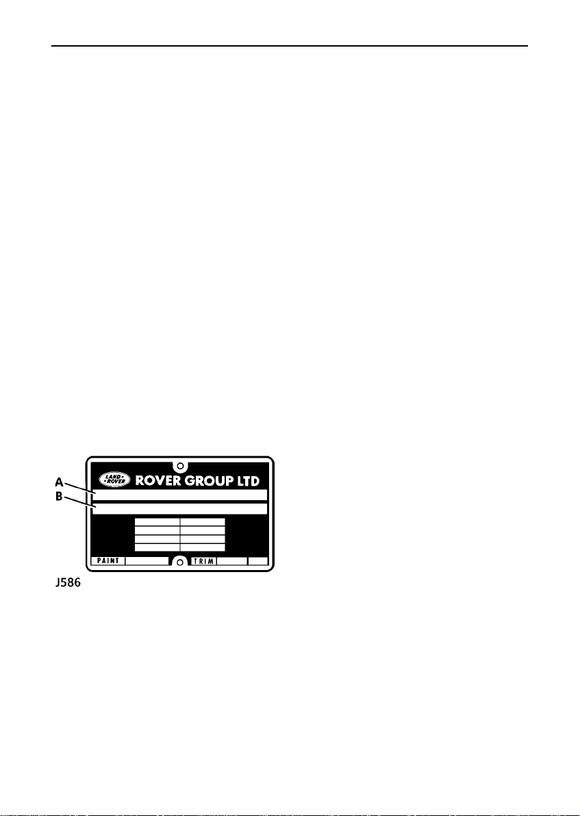
VEHICLE BUILT DATE
This is the calendar month and year in which
the body and power train assemblies were
conjoined and the vehicle was driven from the
production line.
A. Built date
B. Vehicle Identification Number (VIN)
ANTI-THEFT PRECAUTIONS
While it may be difficult to deter the
’professional’carthief, the majority of thefts
are carried out by unskilled opportunists.
Therefore, take vehicle security very seriously
and ALWAYS adopt this simple ’five point’
drill whenever you leave your vehicle - even
for just a few minutes:
• Fully close all the windows (and the
sunroof).
• Remove your valuable belongings (or hide
them out of sight).
• Remove the starter key.
• Engage the steering lock (by slightly
turning the wheel until it locks).
• Lock all the doors.
Thieves are attracted to ’vulnerable’ vehicles.
Even if you have followed the ’five point’ drill,
there is still much you can do to make your
vehicle a less inviting target.
BE SAFE NOT SORRY!
• Park where your vehicle can easily be seen
by householders and passers-by.
• At night, park in well lit areas and avoid
deserted or dimly lit side streets.
• At home, if you have a garage, use it - and
NEVER leave the keys in the vehicle.
• Do not keep important vehicle documents
(or spare keys) in the vehicle - these are a
real bonus for the thief.
4
Page 6

Introduction
IMPORTANT INFORMATION
Remember the breakdown
safety code
If a breakdown occurs while travelling:-
• Wherever possible,consistentwith
road safety and traffic conditions,
the vehicle should be moved off the
main thoroughfare, preferably into a
lay-by. If a breakdown occurs on a
motorway, pull well over to the
inside of the hard shoulder.
• Switch on hazard lights.
• If possible, position a warning
triangle or a flashing amber light at
an appropriate distance from the
vehicle to warn other traffic of the
breakdown (note the legal
requirements of some countries).
• Consider evacuating passengers
through nearside doors onto the
verge as a precaution in case your
Defender is struck by another
vehicle.
5
Page 7

SECTION 2
Controls & instruments
In this section of the handbook you will find
descriptions of the controls and instruments
on your vehicle.
For your own safety, it is most important to
read this section fully and to gain a thorough
understanding of all the controls before
driving.
Section Contents Page
Controls 9.......................................................
Door locks 10.................................................
Seats 12.........................................................
Seat belts 15...................................................
Instruments 19...............................................
Warning lights 20...........................................
Lights & indicators 22....................................
Wipers & washers 23.....................................
Switches 25....................................................
Windows 27...................................................
Sunroof 28.....................................................
Heating & ventilation 29.................................
Air conditioning 32.........................................
Interior equipment 36.....................................
Steps 37.........................................................
7
Page 8
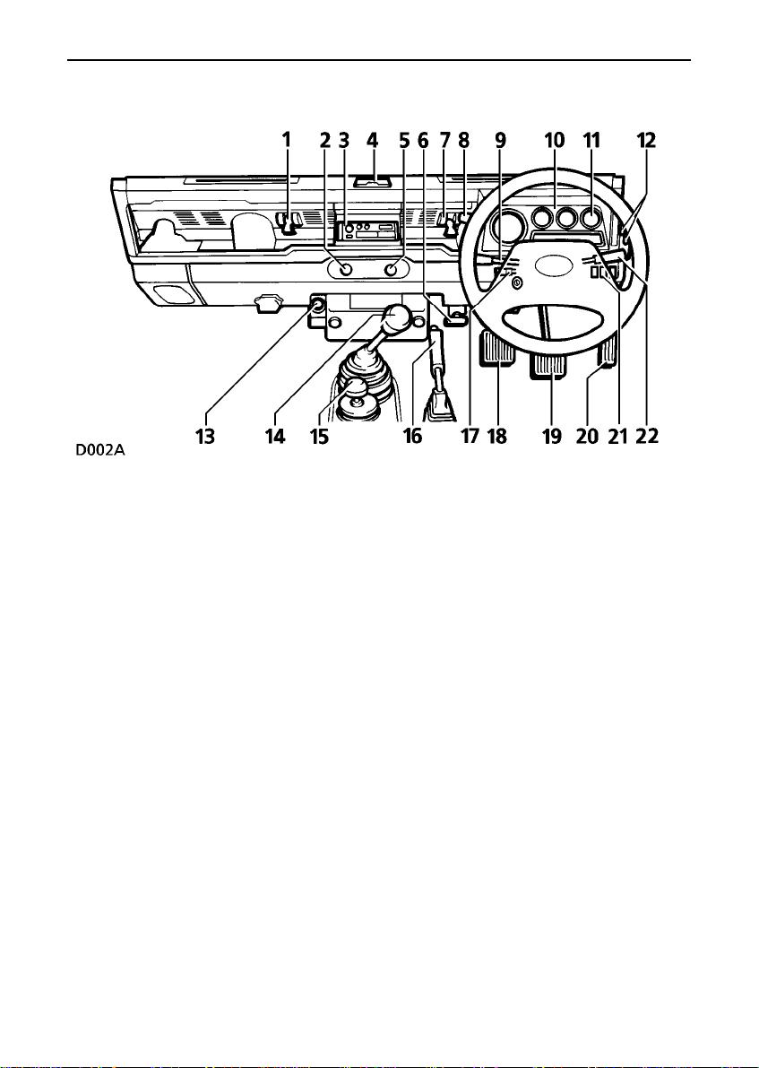
Controls
Right hand steering
1. Ventilator control
2. Rear screen wash/wipe switch
3. Radio/cassetteplayer
4. Ashtray
5. Cigar lighter
6. Bonnet release handle
7. Ventilator control
8. Heater fan control
9. Lighting, direction indicators and horn
control
10.Instrument and warning light pack
11.Clock
12.Heater controls
13.Hand throttle - if fitted
14.Main gear lever
15.Transfer gear lever
16.Handbrake
17.Main lighting switch
18.Clutch pedal
19.Brake pedal
20.Acceleratorpedal
21.Rear fog guard lights, heated rear window
and hazard warning light switches
22.Windscreen wash/wipe control
NOTE: The precise specification and location of controls may vary according to territorial
requirements and from model to model within the vehicle ranges.
9
Page 9
Door locks
Key numbers
WARNING
Keep the spare key in a safe place - NOT IN
THE VEHICLE!
Ensure the key number is recorded on the
Security Card supplied with your literature
pack - DO NOT KEEP THE CARD IN THE
VEHICLE!
Front doors
Turn the key towards the rear of the vehicle to
lock and towards the front to unlock.
Door locking buttons
From inside the vehicle, each door can be
individuallylockedby depressing the
appropriate button.
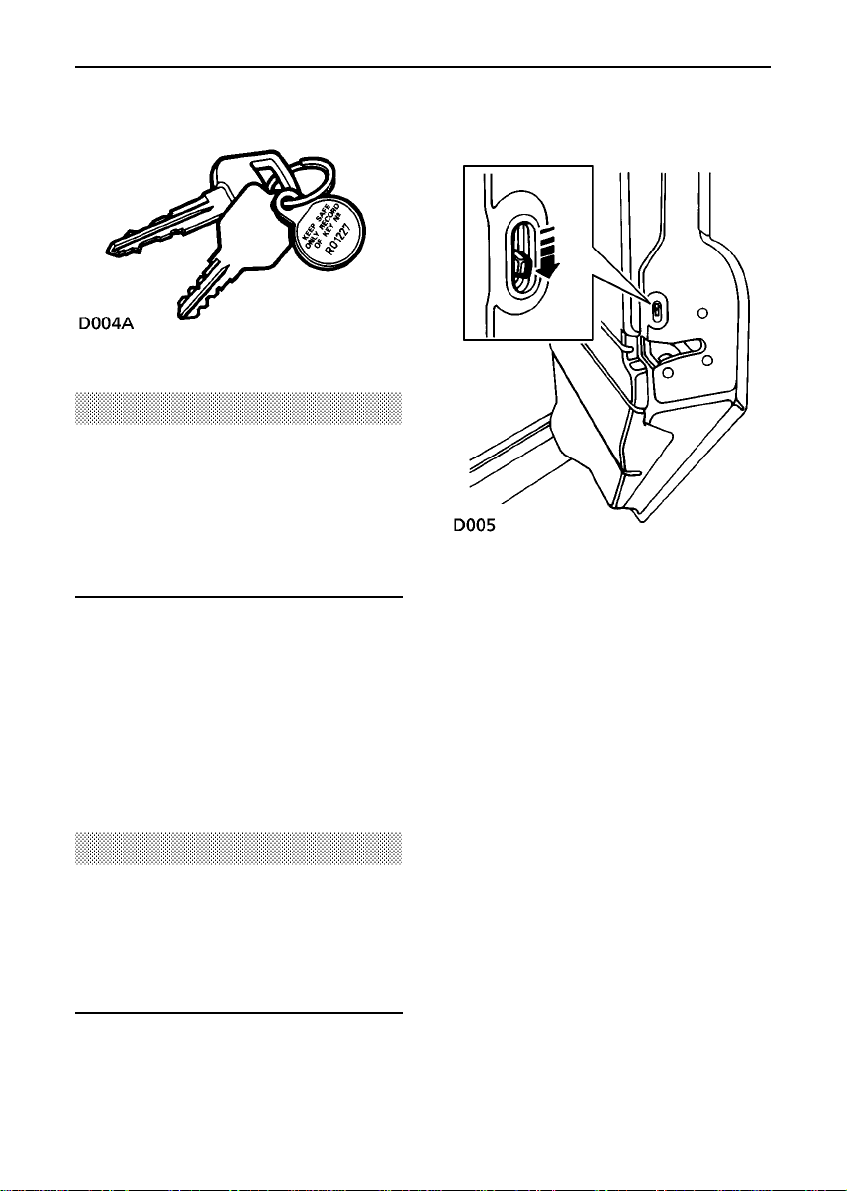
Child-proof locks - 110 Station Wagons
Move the locking levers to the ’ON’ position
(as illustration) to engage.
With the child-proof locks engaged, the rear
doors cannot be opened from inside the
vehicle, thereby avoiding the risk of a door
being opened accidentally while the vehicle is
moving.
WARNING
Take care not to leave the keys inside the
vehicle if the door locking buttons are used
to lock the vehicle from the outside.
This is NOT recommended as a way of
locking the drivers door.
10
Page 10
Door locks
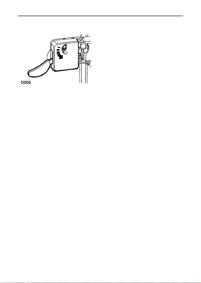
From outside, use the key to lock and unlock.
From inside and with the door closed, push
the locking button up to lock and down to
unlock (as illustration).
Rear door - (if fitted)
11
Page 11
Seats
FRONT SEAT ADJUSTMENT
WARNING
To avoid the risk of loss of control and
personal injury, never adjust the driver’s
seat or seatback while the vehicle is in
motion.
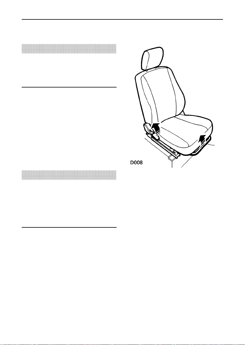
Forward/backward movement
Lift the bar at the front of the seat base to
slide the seat forward or back. Ensure the seat
is locked in position before driving.
Backrest movement
Lift the lever and lean backwards or forwards
to achieve the desired angle, then lower the
lever to lock.
WARNING
DO NOT allow front seat occupants to travel
with the seat backs reclined steeply
rearwards. Optimum benefit is obtained
from the seat belt with the seat back angle
set to 25 degrees from the upright (vertical)
position.
12
Page 12
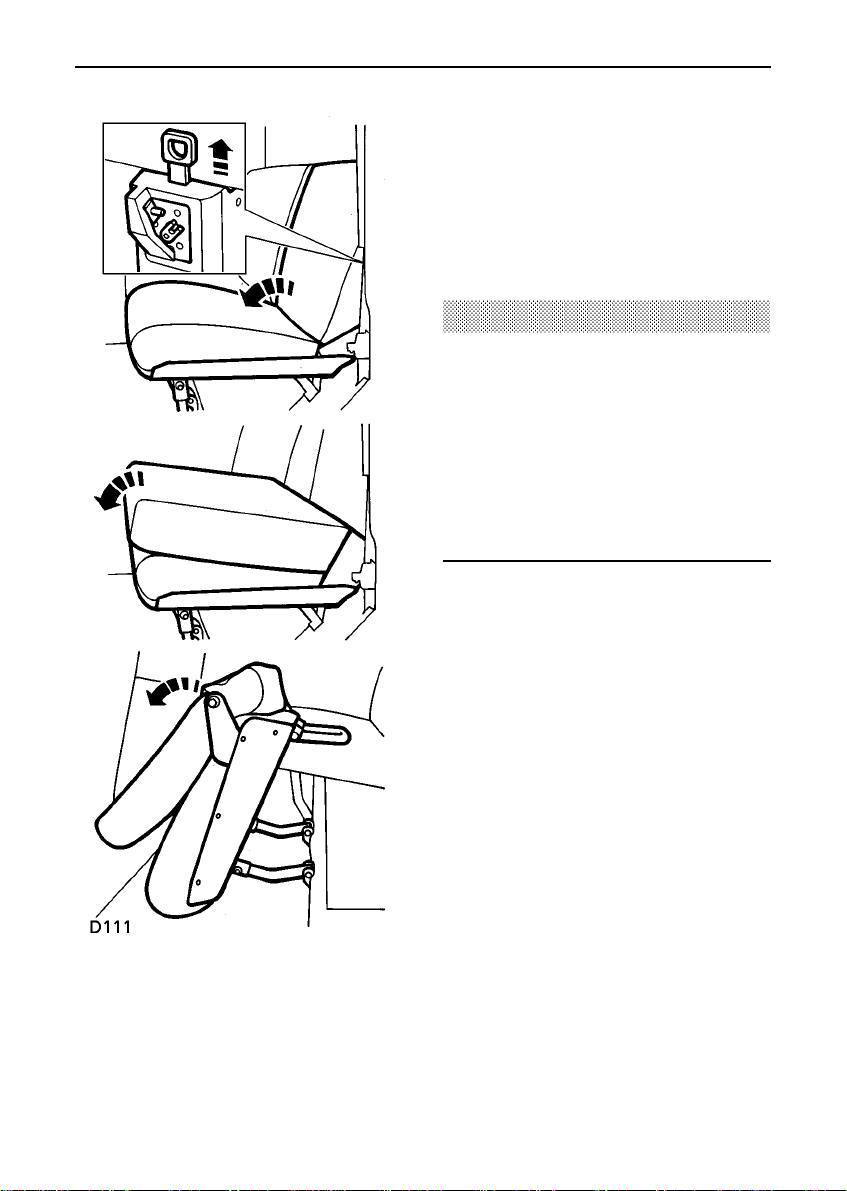
Seats
FOLDING THE REAR SEATS - (if fitted)
Before folding the rear seats;
• Slide the front seats forward.
• Ensure that the outer rear seat belts are
correctly stowed in their belt clips.
• Pass the seat belt locks through the
junction of the backrest and the cushion
and into the loadspace.
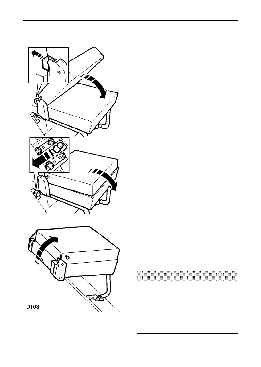
Individually split rear seats
NOTE: The two outer seats must be folded
first, thereby releasing the centre seat.
Outer seats;
1. Release the catch (see first inset).
2. Fold the backrest forward.
3. Slide back the bolt (see second inset).
4. Lift and fold the seat base forwards.
Centre seat;
5. Release the catch - as (1).
6. Fold the backrest forward.
7. Lift and fold the seat base forwards.
When returning the backrest to the upright
position, ensure it is securely latched in place
before driving.
WARNING
DO NOT adjust the seats while the vehicle is
in motion.
When the seat is erected, the latching
mechanism should be visually checked and
physically tested to ensure that the latch is
secure before driving.
13
Page 13
Seats
60/40 split rear seats
1. Pull up the release catch.
2. Fold the backrest forward.
3. Lift and fold the seat base forward.
4. Fold away the seat stand.
WARNING
DO NOT adjust the seats while the vehicle is
in motion.
When re-erecting the seats, ensure that the
seat stands are properly positioned.
When the seat is erected, the latching
mechanism should be visually checked and
physically tested to ensure that the latch is
secure before driving.
14
Page 14

Seat belts
SEAT BELT SAFETY
Seat belts are life saving equipment.
In a collision, unrestrained passengers can be
thrown around inside the vehicle, or possibly
thrown out of the vehicle, resulting in injury to
themselves and to other occupants. DO NOT
take chances with safety!
• DO make sure ALL passengers are
securely strapped in at all times - even for
the shortest journeys.
• ALWAYS adjust seat belts so that the
diagonal belt passes across the shoulder
without slipping off or pressing on the
neck.
• DO have seat belts checked if the vehicle
has been involved in an accident.
• DO NOT drive the vehicle if the seat backs
are reclined more than 15 degrees. Seat
belts are only effective when they are
properly positioned on the body.
• Care should be taken to avoid
contamination of the webbing with
polishes, oils and chemicals, and
particularlybatteryacid.Cleaningmay
safely be carried out using mild soap and
water. The belt should be replaced if
webbing becomes frayed, contaminated or
damaged.
• DO NOT allow foreign matter (particularly
sugary food and drink particles) to enter
the seat belt locks - such substances can
render the locks inoperative.
WARNING
Each belt assembly must only be used by
one occupant; it is dangerous to put a belt
around a child being carried on the
occupant’s lap.
NOTE: Pregnant women should ask a doctor
for advice about the safest way to wear seat
belts.
WARNING
Seat belts are designed to bear upon the
bony structure of the body, and should be
worn low across the front of the pelvis, or
the pelvis, chest and shoulders, as
applicable; wearing the lap section of the
belt across the abdominal area must be
avoided.
Seat belts should be adjusted as firmly as
possible, consistent with comfort, to provide
the protection for which they have been
designed. A slack belt will greatly reduce
the protection afforded to the wearer.
It is essential to replace the entire assembly
after it has been worn in a severe impact,
even if damage to the assembly is not
obvious.
Belts should not be worn with straps
twisted.
15
Page 15
Seat belts
WARNING
At all times, occupants should wear a seat
belt for their protection in the event of a
collision or sudden stop. In some
circumstances, perhaps due to the vehicle
being on a slope, the automatic locking
mechanism may engage, preventing the
initial extension of the belt. This is not a
fault - ease the belt free and use it.
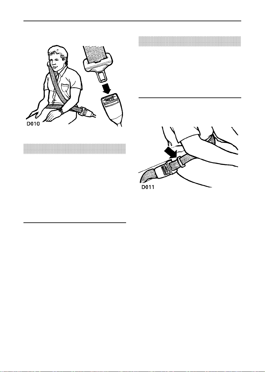
Fastening the inertia reel belts
Draw the belt over the shoulder and across
the chest, and insert the metal tongue plate
into the lock nearest the wearer - a ’click’
indicates that the belt is securely locked.
Seat belts are designed to bear upon the bony
structure of the body (pelvis, chest and
shoulders) and can only be worn safely with
the webbing crossing the shoulder MIDWAY
BETWEEN THE NECK AND THE EDGE OF THE
SHOULDER and with the seats in a normal
UPRIGHT position - DO NOT allow the front
passenger to travel with the seat steeply
reclined.
WARNING
No modifications or additions should be
made by the user, which will either prevent
the seat belt adjusting devices from
operating to remove slack, or prevent the
seat belt assembly from being adjusted to
remove slack.
Lap belts
To adjust, pull the slider along the belt and
feed the webbing through the buckle until the
belt is comfortably tight. When not in use, the
lap belts should be fastened.
16
Page 16

Seat belts
Infant and child restraints
All infant and child restraint systems are
designed to be secured in vehicle seats by
means of a lap belt or the lap portion of a
lap/shoulder belt.
When installing and using any infant or child
restraint system, always follow the
instructions provided by the manufacturer
concerning installationand use. Failure to
properly secure the child restraint system in
the vehicle can endanger the child in a
collision or sudden stop and cause injury to
other passengers.
Centre and inward facing seats are fitted with
lap belts which can be manually tightened to
secure an infant or child restraint system.
Older children should use the lap/shoulder
belt fitted to the outer rear seating positions.
Never leave a child unattended in your
vehicle.
WARNING
Infants and children too small for seat belts
should be restrained in a child safety seat or
restraint system, appropriate to their age
and/or size, and which is approved for use
in your vehicle. Always ensure that the
manufacturer’s fitting instructions are
followed exactly.
• DO NOT allow a baby or infant to be
carried on the lap. The force of a crash
can increase the effective body weight
by as much as 30 times, making it
impossible to hold on to the child.
• DO NOT use a child seat that ’hooks’
over a seatback, it is not secure!
• Accident statistics show that children are
safer when properly restrained in the
rear seating positions than in the front.
However, if a forward facing child seat
suitable for the size of child is available
and it is necessary for a child to travel in
the front, set the seat fully rearwards
and use an approved FORWARD FACING
child seat - DO NOT INSTALL
REARWARD FACING CHILD SEATS IN
ANY FRONT PASSENGER SEAT
POSITION.
17
Page 17

Seat belts
Caring for seat belts
Regularly inspect the belt webbing for signs of
wear, paying particular attention to the fixing
points and adjusters. Always replace a seat
belt that has withstood the strain of an impact
or shows signs of fraying.
DO NOT bleach or dye the webbing. Clean the
webbing using warm water and non-detergent
soap only - allow to dry naturally and DO NOT
retract the belt until completely dry.
Testing inertia reel belts
From time to time carry out the following
tests:
1. With the seat belt fastened, give the
webbing near the buckle a quick upward
pull. The buckle must remain securely
locked.
2. With the seat belt unfastened, unreel the
webbing to the limit of its travel. Check
that unreeling is free from snatches and
snags.
3. With the webbing half unreeled, hold the
tongue plate and give it a quick forward
pull. The safety mechanism must lock
automaticallyand prevent any further
unreeling.
18
Page 18
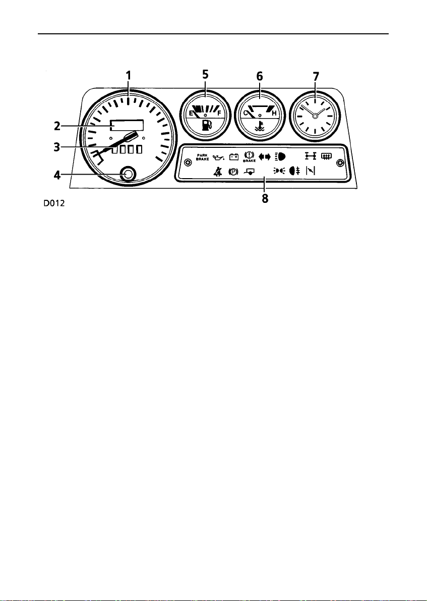
Instruments
1. Speedometer
Indicates road speed in miles and/or
kilometres per hour.
2. Total distance recorder
Indicates the total distance travelled by the
vehicle.
3. Trip recorder
Records individual journey distances.
4. Trip recorder reset button
Press to return trip recorder to zero.
5. Fuel gauge
The pointer indicates the fuel level when the
starter switch is turned to position ’II’.
6. Temperature gauge
Once the engine coolant has reached its
normal operating temperature, the pointer
should remain between the ’C’ (cold) and
’H’ (hot) segments. If the pointer enters the
’H’ segment, stop the vehicle as soon as
safety permits and seek qualified assistance
before continuing.
7. Clock
To adjust the time, depress and rotate the
button in the centre of the clock face.
NOTE: The clock will need to be reset if the
battery has been disconnected.
19
Page 19
Warning lights
8. Warning lights
The specification of the warning lights will
vary according to model and market
requirements.
The warning lights are colour coded as
follows:
RED lights are warnings.
WARNING
DO NOT drive if a RED warning light remains
on once the engine is running or illuminates
whilst driving.
GREEN & BLUE lights indicate that a unit is
operating.
AMBER lights show that a unit is operating
and should be switched off (or rectified) as
soon as conditions allow.
Low engine oil pressure - RED
Illuminates as a bulb check when
the starter switch is turned to
position ’II’ and extinguishes when the engine
is running. If it remains on, or illuminates
whilst driving, STOP THE VEHICLE as soon as
safety permits and seek qualified assistance
before continuing. Always check oil levels
when this light illuminates.
NOTE: At very low ambient temperatures, the
light may take several seconds to extinguish.
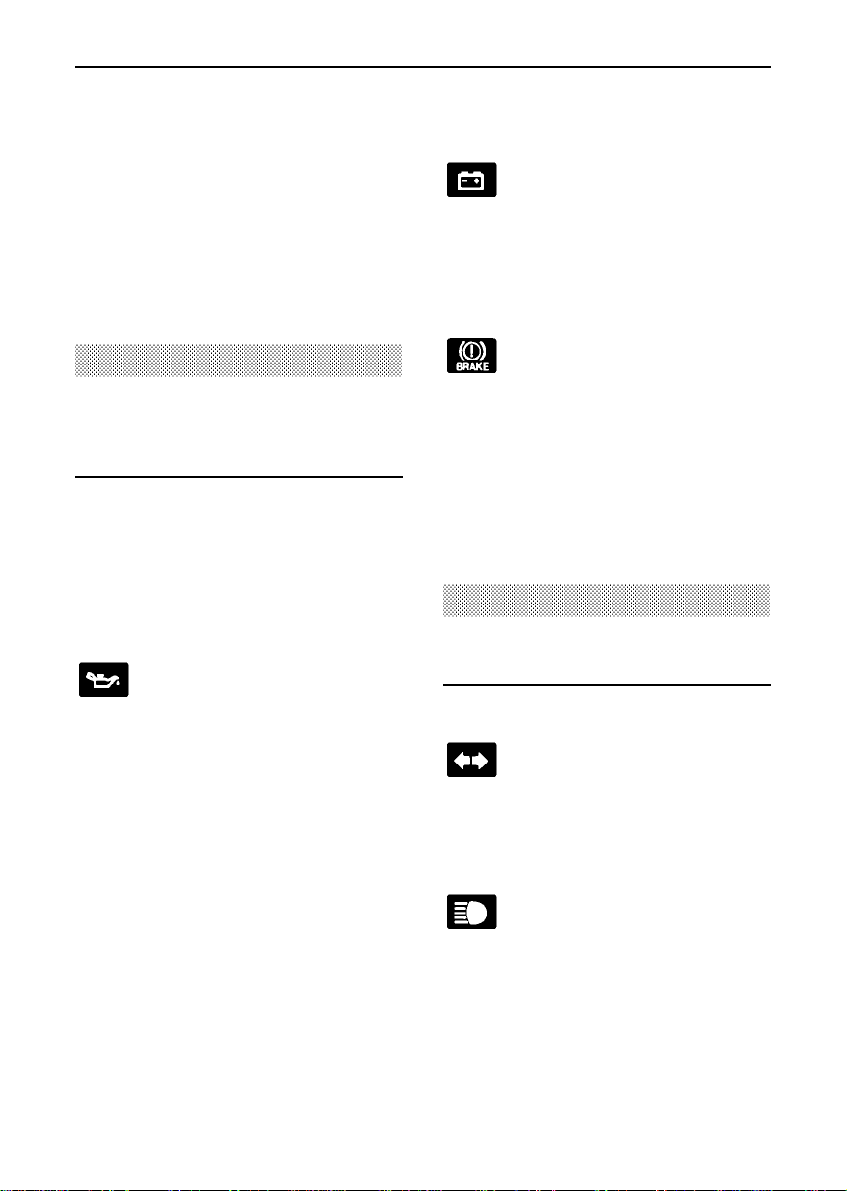
Battery charging - RED
Illuminates as a bulb check when
the starter switch is turned to
position ’II’ and extinguishes when the engine
is running. If it remains on, or illuminates
whilst driving, a fault is indicated. Seek
qualified assistanceurgently.
Brake system check - RED
Illuminates as a bulb check when
the starter switch is turned to
position ’II’ and extinguishes when the engine
is running and the handbrake is released. If it
remains on, or illuminates whilst driving, a
fault with the braking system is indicated.
STOP THE VEHICLE as soon as safety permits
and seek qualified assistance before
continuing.
WARNING
DO NOT drive the vehicle while the brake
warning light is illuminated.
Direction indicators - GREEN
Flashes in conjunction with the
direction indicators. If the light
does not illuminate, this may indicate a bulb
failure in the warning light pack or in one of
the direction indicator lights.
Headlight main beam - BLUE
Illuminates whenever the main
beam headlights are on.
20
Page 20

Warning lights
Differential lock - AMBER
Illuminates whenever the
differential lock is engaged.
If the light remains on after the differential
lock is disengaged, transmission ’wind up’
may be present. Reversing for a short
distance and then going forward will usually
’unwind’ the transmission. If the light remains
on, contact your dealer as soon as possible.
Heated rear screen - AMBER
Illuminates when the rear screen
heater is operating.
Trailer direction indicators GREEN
Flashes in conjunction with the
vehicle direction indicatorlights to show that
all trailer indicator lights are functioning
correctly. In the event of a bulb failure on the
trailer, the warning light flashes once and then
remains off.
NOTE: When a trailer is not fitted, the
warning light will only flash once.
Side lights - GREEN
Illuminates whenever the side
lights are on.
Rear fog guard lights - AMBER
Illuminates whenever the rear fog
guard lights are on.
REMEMBER: In clear conditions, rear fog
guard lights can dazzle other road users. Use
ONLY when visibility is severely restricted.
Cold start - AMBER
Petrol engines:
Illuminates when the cold start
control is operating. DO NOT operate the cold
start control longer than necessary.
Diesel engines:
Illuminates whenever the starter switch is
turned to position ’II’ if the engine is cold.
WAIT for the light to extinguish before starting
the engine.
Handbrake - RED (if fitted)
In some markets, the light
illuminates when the starter
switch is turned to position ’II’ and the
handbrake is applied. The light should
extinguish when the handbrake is fully
released.If the light remains on or illuminates
while driving, seek qualified assistance before
continuing.
Seat belt warning - RED
(if fitted)
In some markets, if the driver’s
seat is occupied, the light illuminates when
the starter switch is turned to position ’II’. The
light extinguishes as soon as the driver’s seat
belt is fastened. ALWAYS fasten your seat belt
BEFORE driving!
21
Page 21
Lights & indicators
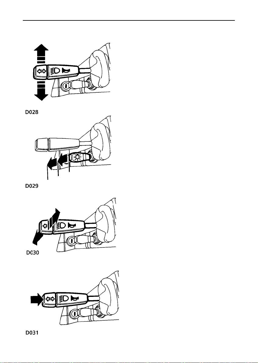
Direction indicators
Move the lever DOWN to indicate a LEFT turn,
and UP to indicate a RIGHT turn (the GREEN
warning light on the instrument panel will
flash in time with the direction indicators).
Hold the lever part-way up or down against
spring pressure to indicate a lane change.
Main light switch
Lever position;
• Static - all lights off
• First position - side, tail and instrument
panel lights on (see ’Dim-dip’ headlights)
• Second position - headlights on
Headlight main beam and ’flash’
With the headlights switched on, push the
lever away from the steering wheel to activate
main beam (BLUE warning light illuminates).
To flash the headlights, pull the lever part-way
towards the steering wheel and then release.
Horn
Press end of the lever to operate the horn.
22
Page 22
Lights & indicators
WARNING
To prevent possible overload damage to the
linkage or the wiper motors in either
freezing or extremely hot conditions, care
must be taken to ensure that the wiper
blades are not adhering to the glass before
operating the wipers.
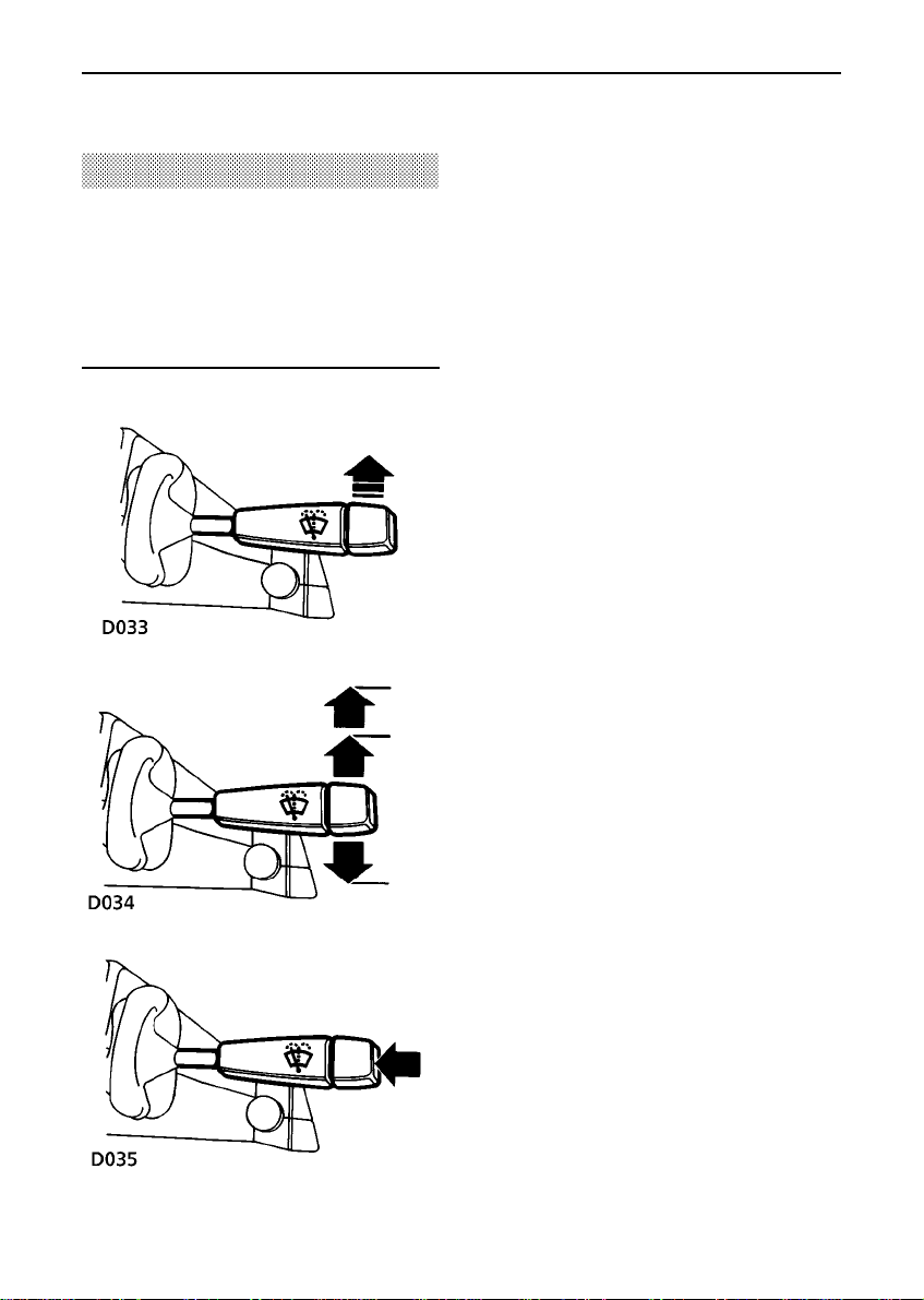
WINDSCREEN WIPERS
• Single wipe
Push the lever up against spring pressure
and release immediately.
NOTE: With the lever held up, the wipers will
continue operating at high speed until it is
released.
• Intermittent wipe
Pull lever down.
• Normal speed wipe
Push lever up to first position.
• Fast speed wipe
Push lever up to second position.
• Windscreen washer
Press to operate (the wipers will also
operate).
23
Page 23
Wipers & washers
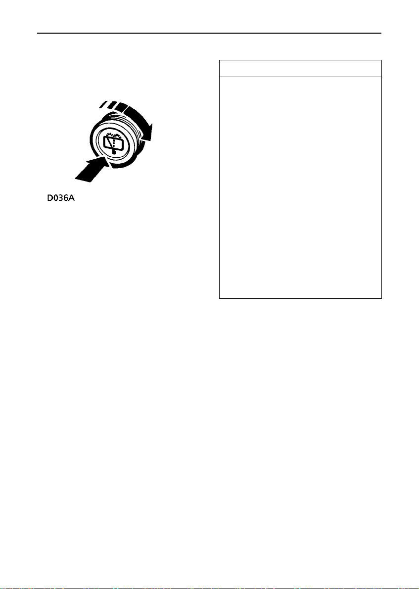
Rear window wash/wipe
The rear window wash/wipe only operates
with the starter switch turned to position ’II’.
• Press and hold to operate the washer.
• Rotate clockwise and hold to operate the
wiper for the required duration.
IMPORTANT INFORMATION
• DO NOT operate the wipers on a dry
screen.
• In freezing or very hot conditions,
ensure that the blades are not frozen
or stuck to the glass.
• In winter, remove any snow or ice
from around the arms and blades,
including the wiped area of the
windscreen and the heater air
intakes.
NOTE: If the wiper blades have stuck to
the glass, a thermal cut-out may
temporarily prevent the wiper motor from
operating. If this is the case, switch the
wipers off, free them from the
obstruction and then switch on again.
24
Page 24
Switches
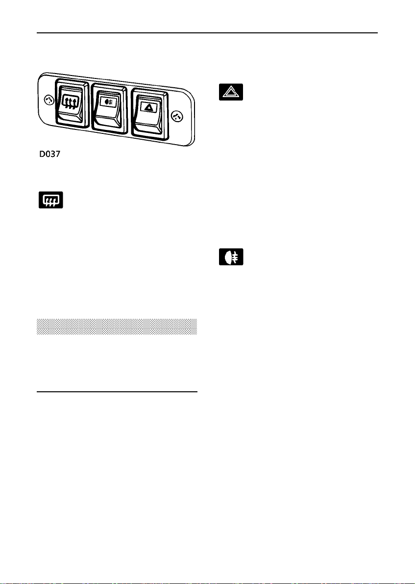
Heated rear window (if fitted)
Press the lower portion of the
switch to operate; press the
upper portion to switch off. The
switch indicator illuminates while the heating
elements are switched on and extinguishes
when they are turned off.
NOTE: If the electricalsystem is being
overloaded a cut-out switch will deactivate the
rear window heater until such time that the
alternator can maintain sufficient charge.
WARNING
DO NOT stick labels over the heating
elements, and DO NOT scrape or use
abrasive materials to clean the inside of the
rear window.
Hazard warning lights
Press the lower portion of the
switch to operate (switch
indicator illuminates);allthe
direction indicator lights (including those
fitted to a trailer) will flash in conjunction with
each other.
Use ONLY in an emergency to warn other
road users when your stationary vehicle is
causing an obstruction, or is in a hazardous
situation. Switch off by pressing the upper
portion before moving away.
Rear fog guard lights (if fitted)
Press the lower portion of the
switch to operate (indicator light
illuminates);pressthe upper
portion to switch off. The lights operate ONLY
with the headlights switched on, and
extinguish when the headlights are switched
off. However, DO remember to switch the fog
guard lights off as soon as visibility is clear whilst the switch remains on, the fog guard
lights will illuminate automaticallywhenever
the headlights are turned on.
REMEMBER: In clear conditions, rear fog
guard lights can dazzle other road users. Use
only when visibility is severely restricted.
25
Page 25
Switches
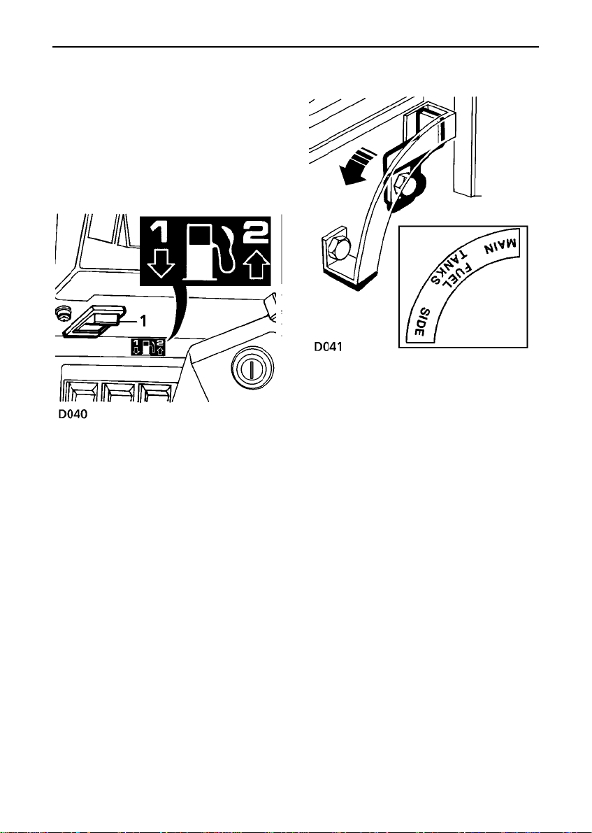
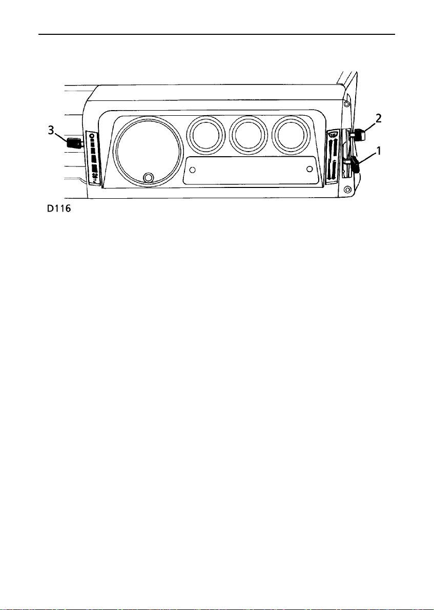
Fuel tank changeover switch
(if fitted)
On vehicles fitted with an additional (optional)
fuel tank, the fuel supply can be switched
between tanks as follows;
Petrol engines:
The switch (1) is located under the dashboard
below the instrument panel. Press the lower
portion of the switch to select Tank 1 and the
upper portion to select Tank 2.
Diesel engines:
The combined changeover tap and switch is
located on the heelboard. Pull the lever up to
the vertical position to select the Main fuel
tank and push the lever down to the horizontal
position to select the Side tank.
NOTE: The fuel gauge on the instrument
panel will indicate the fuel level of the selected
tank.
26
Page 26
Windows
WINDOWS
Front/rear windows;
Raise or lower the window by rotating the
handle mounted on the door trim pad.
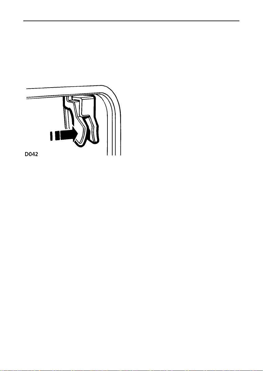
Sliding rear windows; (if fitted)
To open, press the catch tongues together,
slide the window to the desired position and
release the catch, ensuring that it locates
securely in the sockets, locking the window in
position.
27
Page 27
Sunroof
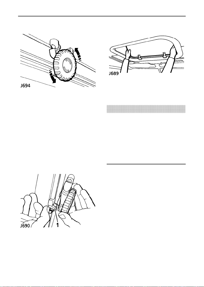
SUNROOF (if fitted)
The sunroof can be opened to varying degrees
or, if required, can be removed completely.
To OPEN the roof:
Turn the hand wheel anti-clockwise to give the
desired opening.
To CLOSE the roof:
Turn the hand wheel clockwise until resistance
is felt.
To REMOVE the roof:
Remove the sunroof by tilting upwards and
lifting rearwards to disengage the locating
lugs.
WARNING
DO NOT store the sunroof loose in the
vehicle.
DO NOT allow passengers to extend any part
of their bodies through the sunroof while the
vehicle is moving.
DO NOT remove the sunroof whilst the
vehicle is moving.
Open the sunroof fully and push the catch (1)
rearwards to disengage the hand wheel
mechanism.
Refit the sunroof by following the same
procedure in reverse.
28
Page 28
Heating & ventilation
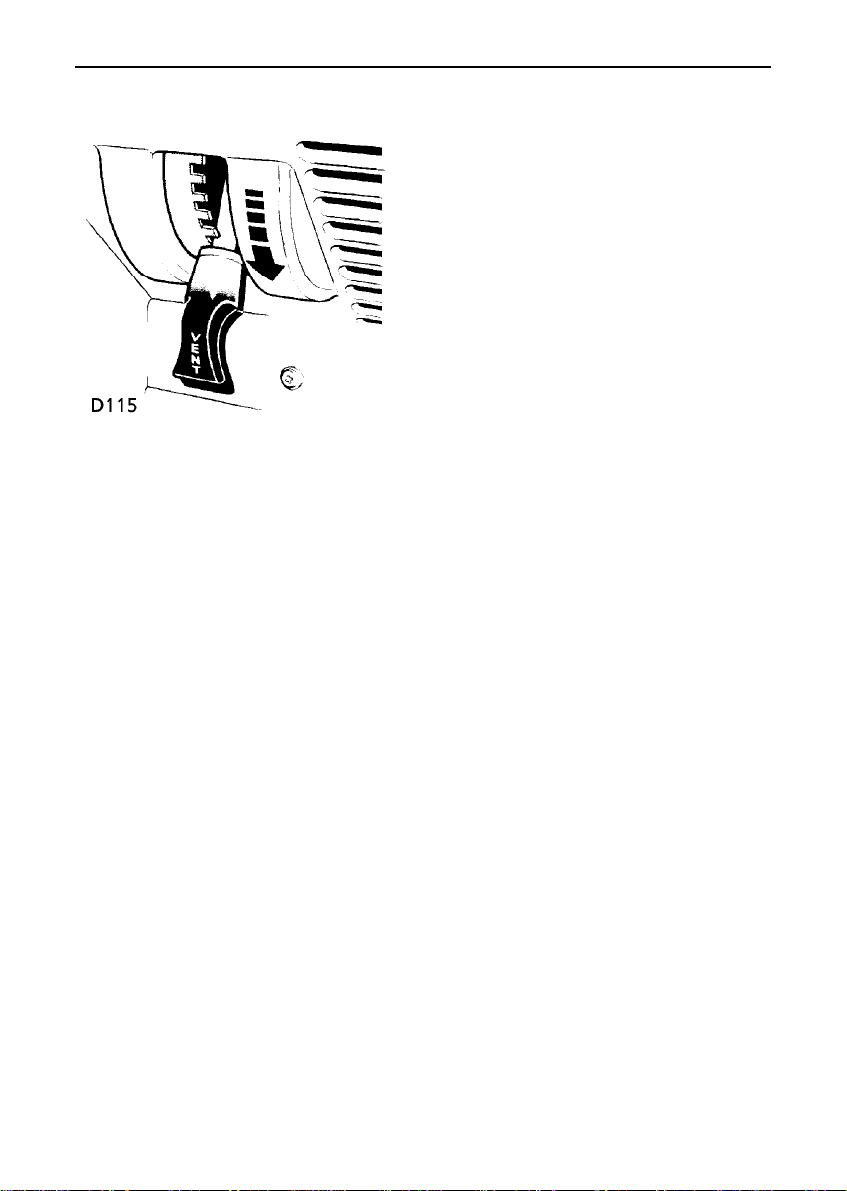
Fresh air vents
To open the two vents in the windscreen
frame, push the lever to the right and then
downwards to the desired position and
release.
The temperature of air supplied to the fresh air
vents is not controlled by the heater.
NOTE: For vehicles fitted with an air conditioning system, the location and operation of air vents is
described on a later page (see ’Air conditioning’).
29
Page 29
Heating & ventilation
HEATER CONTROLS
NOTE: For vehicles fitted with an air
conditioning system, the heater controls are
described on a later page (see ’Air
conditioning’).
1. Temperature control
Move the lever downwards (towards the
RED segment) to increase air temperature,
or upwards (towards the BLUE segment)
to reduce air temperature.
2. Air distribution control
• Lever fully up - windscreen vents only.
• Lever midway - foot level and windscreen
vents.
• Lever fully down - foot level vents (also
provides some air to the windscreen).
3. Fan speed control
Move the control downwards to
progressivelyincreasefan speed. With the
control at ’0’ the fan is stationary and the
volume of air entering the passenger
compartment is solely dependent upon the
ram effect of the vehicle moving through
the air.
30
Page 30

Heating & ventilation
USING YOUR HEATER
Ensure the front grille and the air intake grille
on the front wing are kept clear of
obstructions (especiallysnowand ice).
The following examples of basic heater
settings are intended as a general guide; the
air distribution, temperature and blower
controls can then be further adjusted to suit
your comfort requirements.
Always remember that full heating is not
availableuntil the engine has reached its
normal operating temperature.
Maximum heating
• Temperature control - fully down.
• Distribution control - midway.
• Fan speed control - fully down.
• Fresh air vents - fully closed.
Demisting and defrosting
• Temperature control - fully down.
• Distribution control - fully up.
• Fan speed control - fully down.
• Fresh air vents - fully open for demisting
(closed for defrosting).
• Opening a window may improve
ventilation.
Maximum ventilation
• Temperature control - fully up.
• Distribution control - fully down.
• Fan speed control - fully down.
• Fresh air vents - fully open.
31
Page 31

Air conditioning
Location of air vents - (LH steering illustrated)
2. Air conditioning switch
Press the switch (indicator light
illuminates)to activate the air
conditioning. Press again to switch off.
3. Air recirculation control
Move the lever fully upwards to activate air
recirculation.Move the lever fully
downwards to cancel recirculation.
AIR CONDITIONING
(if fitted) - LH steering
CONTROLS
1. Temperature control
Move the lever upwards (RED) to increase
air temperature, or downwards (BLUE) to
reduce air temperature.
NOTE: Prolonged recirculation may cause the
windows to mist up.
4. Air distribution control
• Lever fully up - air to windscreen vents
(also provides some air to the footwell).
• Lever midway - air to fascia vents (also
provides some air to the footwell).
• Lever fully down - air to footwell vents
(also provides some air to the
windscreen).
5. Fan speed control
Move the lever to the right to
progressivelyincreasethe fan speed.
32
Page 32

Air conditioning
Air conditioning (if fitted) - RH steering
1. Temperature control
Move the lever to the right (RED) to
increase air temperature,or to the left
(BLUE) to reduce air temperature.
2. Air conditioning indicator light
Illuminates when the air conditioning
system is operating.
3. Air conditioning switch
Press the right hand portion of the switch
to activate the air conditioning (indicator
light illuminates). Press the left hand
portion to switch off.
NOTE: Air conditioning should only be
activated when the engine is running.
CONTROLS
4. Fan speed control
Move the lever upwards to progressively
increase the fan speed.
5. Air distribution controls
• Push left hand button for air to fascia
vents (also provides some air to footwell).
• Push middle button for air to windscreen
vents (also provides some air to footwell).
• Push right hand button for air to footwell
vents (also provides some air to
windscreen).
6. Air recirculation switch
Press the left hand portion of the switch to
activate air recirculation.Pressthe right
hand portion for fresh air.
NOTE: Prolonged recirculation may cause the
windows to mist up.
33
Page 33

Air conditioning
USING THE AIR CONDITIONING
Air conditioning provides additional cooling to
the vehicle interior and also reduces the
moisture content of the air.
The air conditioning system will only operate
with the fan switched on and the engine
running. It is also important to keep the
windows (and sunroof) closed during
operation.
Operation of the air conditioning system,
places an additional load on the engine which,
in very hot conditions and if the engine is
required to work unusually hard, could result
in high engine temperatures. If the
temperature gauge pointer reaches the RED
zone, turn the air conditioning off until engine
temperature returns to normal.
Air recirculation
The air recirculation mode prevents the
heating system from taking in fresh air from
outside the vehicle. Instead, the air already
inside the vehicle is recirculated, thus
preventing the entry of traffic fumes. In cold
weather, air recirculationalso enables warmer
air to be used to defrost the windscreen when
the engine is still cold.
Points to remember:
• If the temperature inside the vehicle is
higher than that outside when you start
the engine, it will take time for the air
conditioning to become fully effective. It is
best to ventilate the vehicle by opening the
windows and operating the fan for a brief
period before switching on the air
conditioning. Remember to close the
windows whenever the air conditioning is
operating.
• Operating the air conditioning takes power
from the engine and consequently
increasesfuel consumption.
• All air conditioning systems need to be
operated for a short while every week
(even in winter) to maintain them in peak
condition.
• The air conditioning system will also
dehumidify air. The surplus water
produced by this process is expelled from
the system via drain tubes beneath the
vehicle. This may result in a small pool of
water forming on the road when the
vehicle is stationary and is not a cause for
concern.
WARNING
The air recirculation mode can cause the
windscreen to mist up. If this happens,
switch off air recirculation immediately.
34
Page 34

Air conditioning
The following examples of heater and air
conditioning settings are included for
your guidance:
Maximum heating
• Air conditioning switch - OFF.
• Temperature control - set to RED position.
• Distribution control - set to footwell
position.
• Fan speed control - set to maximum
speed.
• Air recirculation control - set to
recirculation.
Demisting and defrosting
• Air conditioning switch - ON.
• Temperature control - set to RED position.
• Distribution control - set to windscreen
position.
• Fan speed control - set to maximum
speed.
• Air recirculation control - set to fresh air.
Maximum ventilation
• Air conditioning switch - OFF.
• Temperature control - set to BLUE
position.
• Distribution control - set to footwell
position.
• Fan speed control - set to maximum
speed.
• Air recirculation control - set to fresh air.
Normal cooling
• Air conditioning switch - ON.
• Temperature control - set to BLUE
position.
• Distribution control - set to fascia position.
• Fan speed control - set to desired speed.
• Air recirculation control - set to fresh air.
Maximum cooling
• Air conditioning switch - ON.
• Temperature control - set to BLUE
position.
• Distribution control - set to fascia position.
• Fan speed control - set to maximum
speed.
• Air recirculation control - set to
recirculation.
Switch off air recirculation when desired
temperature is reached.
Reducing humidity
These settings are suitable for normal driving.
• Air conditioning switch - ON.
• Temperature control - set to midway.
• Distribution control - set to windscreen
position.
• Fan speed control - set to midway.
• Air recirculation control - set to fresh air.
35
Page 35

Interior equipment
INTERIOR LIGHTS
With the switch midway between the ’ON’ and
’OFF’ positions, the light will illuminate
automaticallywhenevera door is opened and
remain illuminated for approximately 15
seconds after ALL the doors are closed, or
until the starter switch is turned on. When
alighting from the vehicle, the interior lights
will fade and then extinguish as soon as the
last door is closed.
NOTE: Any subsequent opening and shutting
of doors prior to the starter switch being
turned on again, will cause the 15 second
delay feature to operate.
NOTE: If a door remains open for eight
minutes, a ’time-out’ function will extinguish
the lights to avoid discharging the battery.
CIGAR LIGHTER
With the starter switch turned to position II,
press the lighter in to heat up. When it has
reached the correct temperature it will partially
eject and can then be withdrawn for use.
• ONLY hold the cigar lighter by the handle.
• DO NOT use the ashtray for disposing of
waste paper or other combustible
materials.
• DO NOT plug accessories into the cigar
lighter socket unless they are approved by
Land Rover.
ASHTRAY
Lift the lid of the ashtray to open. To remove,
carefully prise the ashtray out of the fascia
panel.
36
Page 36

Steps
Steps (if fitted)
The steps can be folded up or down as
required.
37
Page 37

SECTION 3
Driving & operating
Section Contents Page
Starter switch & steering lock 41....................
Starting & driving 42......................................
Catalytic converter 50.....................................
Fuel 52............................................................
Gearbox & transmission 54............................
Brakes 59.......................................................
Towing & load carrying 61.............................
Emergency starting 64....................................
Vehicle recovery 66........................................
Ancillary equipment 68...................................
39
Page 38

Starter switch & steering lock
To unlock the steering column
Insert the ignition key FULLY and turn the
starter switch to position ’I’, while turning the
steering wheel slightly to disengage the lock.
To lock the steering column
Turn the starter switch to position ’0’ and
withdraw the key from the starter switch. Turn
the steering wheel towards the straight ahead
position until the lock engages.
WARNING
DO NOT remove the key or turn the starter
switch to position ’0’ while the vehicle is in
motion. Once the steering lock is engaged,
it is impossible to steer the vehicle.
STARTER SWITCH
The starter switch is located to the left of the
steering column, and uses the following
sequence of key positions to operate the
steering lock, electricalcircuitsand starter
motor.
Position ’0’
Steering locked (if key is removed).
Most lighting circuits are operational,
including: sidelights, headlights, hazard
warning lights and rear fog guard lights.
Position ’I’
Steering unlocked.
Radio/cassetteplayercanbe operated.
Position ’II’
All instruments, warning lights and electrical
circuits are operational.
Position ’III’
Starter motor operates.
Release the key immediately the engine starts
(the key will automatically return to position
’II’).
Note that operation of position ’I’ electrical
functions will be interrupted during engine
cranking.
41
Page 39

Starting & driving
STARTING - DIESEL ENGINES
WARNING
FOR VEHICLES EQUIPPED WITH A
CATALYTIC CONVERTER:
Catalytic converters are easily damaged
through improper use, particularly if the
wrong fuel is used, or if an engine misfire
occurs.
Before starting the engine and driving,
ENSURE you are familiar with the precautions
shown under ’Catalytic converter’ later in this
section.
In particular, you should be aware that
continued use of the starter will result in
unused fuel damaging the catalytic converter.
1. Check that the handbrake is applied and
that the gear lever is in neutral.
2. Switch off all unnecessary electrical
equipment.
3. Insert the starter key and turn the switch
to position ’II’. Wait until the cold start
warning light extinguishes.
In cold weather, or when the battery is in a
low state of charge, depress the clutch pedal
while starting and hold it down until the
engine is running.
In temperate climates, DO NOT operate the
starter for longer than 10 seconds; if the
engine fails to start, switch off and wait 10
seconds before re-using the starter. Please
note that prolonged use of the starter will not
only discharge the battery but may also
damage the starter motor.
WARNING
The engine must not be run above fast idle
speed until the oil pressure warning light
extinguishes to ensure that the engine and
turbo-charger bearings (Tdi models) are
properly lubricated before being run at
speed.
NOTE: When restarting a warm engine, it will
not be necessary to wait for the cold start
warning light to extinguish.
4. Turn the key to position ’III’ to operate the
starter motor; DO NOT press the
acceleratorpedalduring starting, and
RELEASE THE KEY as soon as the engine
is running.
NOTE: In temperate climates, the battery
charging and oil pressure warning lights
should extinguish as soon as the engine is
running.
42
Page 40

Starting & driving
Cold climates
In very cold climates, the battery charging and
oil pressure warning lights may take several
seconds to extinguish. Similarly, engine
cranking times will also increase; at -30° C the
starter motor may need to be operated
continuously for as long as 30 seconds before
the engine will start. For this reason, ensure
that all non-essential electricalequipmentis
switched off.
Warming up
In the interests of fuel economy, it is advisable
to start driving straight away, remembering
that harsh acceleration or labouring the engine
before the normal operating temperature has
been reached can damage the engine.
WARNING
Exhaust fumes contain poisonous
substances which can cause
unconsciousness and may even be fatal.
• DO NOT inhale exhaust gases.
• DO NOT start or leave the engine running
in an enclosed unventilated area, or
drive with the rear door open.
• DO NOT modify the exhaust system from
the original design.
• DO repair exhaust system or body leaks
immediately.
• If you think exhaust fumes are entering
the vehicle have the cause determined
and corrected immediately.
Switching off
To avoid the possibility of damaging the
turbo-charger bearings(Tdi models) through
inadequate lubrication, ALWAYS allow the
engine to idle for 10 seconds before switching
off. Turn the engine off by returning the
starter switch to position ’I’ and then position
’0’ to remove key.
43
Page 41

Starting & driving
STARTING - PETROL ENGINES
1. Check that the handbrake is applied and
that the gear lever is in neutral.
2. Switch off all unnecessary electrical
equipment.
3. If the engine is cold, pull out the cold start
control (if fitted) and turn it clockwise to
lock (see illustration).
4. Insert the starter key and turn the switch
to position ’II’ and then on to position ’III’
to operate the starter motor. DO NOT
press the accelerator pedal during starting
and RELEASE THE KEY as soon as the
engine is running.
In temperate climates DO NOT operate the
starter for longer than 10 seconds. If the
engine fails to start, switch off and wait 10
seconds before re-using the starter. Please
note that prolonged use of the starter will not
only discharge the battery but may also
damage the starter motor.
In temperate climates, the battery charging
and oil pressure warning lights should
extinguish as soon as the engine is running.
In cold weather, or when the battery is in a
low state of charge, depress the clutch pedal
while starting and hold it down until the
engine is running.
Cold climates
In very cold climates, the battery charging and
oil pressure warning lights may take several
seconds to extinguish. Similarly, engine
cranking times will also increase; at -30° C the
starter motor may need to be operated
continuously for as long as 30 seconds before
the engine will start. For this reason, ensure
that all non-essential electricalequipmentis
switched off.
Additionally, in very cold climates, use of a
cylinder block heater will improve the engine’s
starting characteristics.YourLand Rover
dealer can advise you about the supply and
use of a cylinder block heater.
Warming up
In the interests of fuel economy, it is advisable
to start driving straight away, remembering
that harsh acceleration or labouring the engine
before the normal operating temperature has
been reached can damage the engine.
NOTE: Remember to turn off the cold start
control once normal operating temperature is
reached.
44
Page 42

Starting & driving
WARNING
Exhaust fumes contain poisonous
substances which can cause
unconsciousness and may even be fatal.
• DO NOT inhale exhaust gases.
• DO NOT start or leave the engine running
in an enclosed unventilated area, or
drive with the rear door open.
• DO NOT modify the exhaust system from
the original design.
• DO repair exhaust system or body leaks
immediately.
• If you think exhaust fumes are entering
the vehicle have the cause determined
and corrected immediately.
Parking
After bringing the vehicle to a stop, ALWAYS
apply the handbrake and select neutral in the
main gearbox before releasing the footbrake
and switching off the engine.
Switching off
Return the starter switch to position ’I’ and
then to position ’0’ to remove the key.
45
Page 43

Starting & driving
RUNNING-IN (petrol & diesel models)
Proper running-in will have a direct bearing on
the reliability and smooth running of your
vehicle throughout its life.
In particular, the engine, gearbox, brakes and
tyres need time to bed-in and adjust to the
demands of everyday motoring. It is therefore
essential to drive with consideration for the
running-in process for at least the first 800
km (500 miles) and observe the following
advice:
• LIMIT maximum speed to 80 km/h (50
mph) for 4-cylinder engines and 95 km/h
(60 mph) for V8 engines. Initially, drive
the vehicle on a light throttle and only
increase engine speeds once the
running-in distance has been completed.
• DO NOT operate at full throttle or allow the
engine to labour in any gear.
• AVOID fast acceleration and heavy braking
except in emergencies.
EMISSION CONTROL SYSTEM
Land Rover vehicles are fitted with emission
and evaporative control equipment necessary
to meet a number of territorial requirements.
In many countries, it is against the law for
vehicle owners to modify or tamper with
emission control equipment, or to sanction
the unauthorised replacement or modification
of this equipment by a repair shop. In such
cases, the vehicle owner and the repairer may
both be liable for legal penalties.
It is important to remember that only Land
Rover dealers are properly equipped to
perform repairs and to maintain the emission
control system on your vehicle.
46
Page 44

Starting & driving
FUEL ECONOMY
Fuel consumption is influenced by two major
factors:
• How your vehicle is maintained.
• How you drive your vehicle.
To obtain optimum fuel economy, it is
essential that your vehicle is maintained in
accordance with the manufacturer’s service
schedule.
Items such as ignition timing, the condition of
the air cleaner element, tyre pressures and
wheel alignment can have a significant effect
on fuel consumption. But above all, the way in
which you drive is most important. The
following hints may help you to obtain even
better value from your motoring:
• Avoid unnecessary, short, start-stop
journeys.
• Avoid fast starts by accelerating gently and
smoothly from rest.
• Do not drive in the lower gears longer than
necessary.
• Decelerategentlyand avoid sudden and
heavy braking.
• Anticipate obstructions and adjust your
speed accordingly well in advance.
DRIVE GENTLY - SAVE FUEL!
47
Page 45

Starting & driving
IMPORTANT DRIVING INFORMATION
Instruments & warning lights
Before driving, it is important to fully
understand the function of the instruments
and warning lights described in section 2.
NOTE: Red warning lights are of particular
importance, illumination indicatesthat a fault
exists. If a red light illuminates, always stop
the vehicle and seek qualified assistance
before continuing.
Vehicle stability
Your vehicle has a higher ground clearance
and, therefore, a higher centre of gravity than
ordinary passenger cars. This will result in
different handling characteristics.
Inexperienceddriversshould take additional
care, particularlyin off-road driving situations
and when performing abrupt manoeuvres at
inappropriate speeds or on unstable surfaces.
Vehicle height
The overall height of your vehicle exceeds that
of ordinary passenger cars. Always be aware
of the height of your vehicle and check the
availableheadroom before driving through
low entrances. This is particularly important if
the vehicle is fitted with a roof rack or if the
sunroof is open.
Power assisted steering
Power assistance is progressivelyappliedthe
more the steering wheel is turned. For
example; where manual steering effort would
normally be greatest (at slow speeds on
maximum lock), power assistance is greatest.
Similarly, where only minimal steering effort
would normally be required (at high speed
with the wheels straight ahead), then power
assistanceis also minimal, thus enabling the
driver to benefit from apparently consistent
steering effort at all times.
WARNING
Under no circumstances must the steering
wheel be held on full lock for more than
thirty seconds in one minute, otherwise the
steering assembly may be damaged.
NOTE: Power assistance is dependent on the
engine running. If the engine is not running,
greater effort will be required to steer the
vehicle.
48
Page 46

Starting & driving
Tdi engines
If a radiator blind is fitted, it must not obscure
the intercooler section otherwise engine
performance would be adversely affected. If in
doubt, contact a Land Rover dealer.
Auxiliary equipment
WARNING
DO NOT use auxiliary equipment, such as
roller generators, that are driven by one
wheel of the vehicle, as they could cause
failure of the gearbox differential. If the
gearbox differential lock is engaged in an
attempt to avoid damage, the vehicle will
drive itself forward.
49
Page 47

Catalytic converter
CATALYTIC CONVERTER - (if fitted)
The exhaust system on some models of the
Defender, incorporatesa catalytic converter,
which converts poisonous exhaust emissions
from the engine into environmentally less
harmful gases, thereby reducing atmospheric
pollution.
WARNING
The catalytic converter can be easily
damaged through improper use, particularly
if the wrong fuel is used, or if an engine
misfire occurs. For this reason it is VERY
IMPORTANT that you heed the precautions
which follow:
Fuel
• Use ONLY fuel recommended for your
vehicle.
Starting the engine
• DO NOT continue operating the starter if
the engine fails to start after a few
attempts (unburnt fuel may be drawn into
the exhaust system, thereby poisoning the
catalyst) - seek qualified assistance.
• When starting a COLD engine, DO NOT
drive if a misfire is suspected - seek
qualified assistance.
50
Page 48

Catalytic converter
Driving
• Provided the engine has reached its
normal operating temperature, if a misfire
is suspected or the vehicle lacks power
while driving, it may be driven SLOWLY
(at risk of damaging the catalyst) to a
Land Rover dealer for assistance.
• NEVER allow the vehicle to run out of fuel
(the resultant misfire could destroy the
catalyst).
• Engines burning excessive oil (blue smoke
from the exhaust) will progressively
reduce catalyst efficiency.
• On rough terrain, DO NOT allow the
underside of the vehicle to be subjected to
heavy impacts which could damage the
catalytic converter.
• DO NOT overload or excessively rev the
engine.
WARNING
Exhaust system temperatures can be
extremely high - DO NOT park on ground
where combustible materials such as dry
grass or leaves could come into contact with
the exhaust system (in dry weather a fire
could result).
Switching off
• DO NOT switch off the engine while a
forward or reverse gear is selected or
whilst the vehicle is in motion.
Vehicle maintenance
• Any engine misfire, loss of engine
performance or engine run-on, could
seriously damage the catalytic converter.
For this reason, it is vital that unqualified
persons do not tamper with the engine,
and that regular systematic maintenance is
carried out by a Land Rover dealer.
51
Page 49

Fuel
PETROL ENGINES
USE ONLY RECOMMENDED FUEL
4 cylinder engines:
Use 90 RON minimum leaded or unleaded fuel
wherever possible.
V8 engines:
Use 91 - 93 leaded or unleaded fuel wherever
possible.
NOTE: For petrol engined vehicles fitted with
a catalytic converter, 95 RON minimum
unleaded fuel MUST be used - leaded fuel will
seriously damage the catalyst.
The RON value (octane rating) of petroleum
commonly available at garage forecourts will
vary in different countries. The RON value
quoted is the MINIMUM requirement and
whilst this can be safely exceeded, no
advantage in performance or fuel economy
will be gained by using a higher octane fuel.
If heavy engine knock is detected when using
the recommended octane rated fuel, or if
steady engine knocking is present while
maintaining a steady speed on level roads,
contact your dealer for advice.
DIESEL ENGINES
The quality of diesel fuel (Derv) can vary in
different countries and only clean, good
quality fuel should be used. It is important
that the sulphur content of diesel fuel does
not exceed 1%; in Europe all supplies should
be within this limit, but in other parts of the
world, you should check with your supplier.
Ensure the fuel filter element is changed at the
recommended serviceintervalsand clean the
sediment bowl regularly (see ’Owner
maintenance’).
WARNING
On both petrol and diesel engine vehicles, if
the fuel tank is accidentally filled with the
wrong fuel, it is ESSENTIAL that you contact
your dealer BEFORE attempting to start the
engine!
NOTE: An occasional, light, engine knock
while acceleratingor climbing hills is
acceptable.
52
Page 50

Fuel
Fuel filling
WARNING
To avoid any sudden discharge of fuel
caused by excessive air pressure, the cap is
designed to allow the fuel tank to vent
during the first half turn. DO NOT fully
remove the cap until pressure has been
released.
Filling station pumps are equipped with
automatic cut-off sensing to avoid fuel
spillage - only fill the tank until the filler nozzle
automaticallyshuts off. DO NOT attempt to fill
the tank beyond this point or spillage could
result due to expansion of the fuel.
WARNING
DO NOT fully fill the tank if the vehicle is to
be parked on a slope in direct sunlight or
high ambient temperature - expansion of the
fuel could cause spillage.
Empty fuel tank
DO NOT RUN THE FUEL TANK DRY!
In the case of vehicles equipped with a
catalytic converter,running the fuel tank dry
could create an engine misfire capable of
damaging the catalytic converter.
In the case of diesel models, qualified
assistancemay be required to prime the fuel
system before the engine can be restarted.
SAFETY ON THE FORECOURT
Petroleum gases are highly inflammable
and in confined spaces are also explosive.
Always take sensible precautions when
refuelling:
• Switch off the engine.
• Do not smoke or use a naked flame
or light.
• Take care not to spill fuel.
• Do not overfill the tank.
53
Page 51

Gearbox & transmission
MAIN GEARBOX
Your vehicle features a five speed main
gearbox and a two speed transfer box. In
addition, a centre differential in the transfer
box distributes the drive to the front and rear
axles, providing permanent four wheel drive.
By using the main gearbox in conjunction with
the transfer gears, ten forward and two
reverse speeds are available.
The gear positions for the main gearbox are
shown on the gear lever knob. Note that when
the gearbox is in neutral, the gear lever is
spring-loaded to automatically align between
third and fourth gear positions.
Clutch
Take care NOT to use the clutch pedal as a
foot rest. To prevent unnecessary wear,
always keep the left foot well clear of the
clutch pedal, except when changing gear.
WARNING
Do NOT select reverse gear unless the
vehicle is stationary.
54
Page 52

Gearbox & transmission
TRANSFER GEARBOX
The second gear lever is used to select either
the high or low range of gears in the transfer
gearbox and, in addition, also controls the
centre differential (known as the ’DIFF LOCK’).
High range (’H’)
Use high range for all normal road driving and
also for off-road driving across dry, level
terrain.
Low range (’L’)
Use low range gears when moving off from
rest when towing a heavy load, or in any
situation where low speed manoeuvring is
necessary,such as reversing a trailer or
negotiating a boulder strewn river bed; also
use for more extreme off-road conditions
where progress in high range cannot be
maintained.
Neutral (’N’)
With the transfer lever in neutral, drive cannot
be transmitted to the road wheels, regardless
of the position of the main gear lever. Use
transfer neutral when being towed or when
using winching or power take off facilities.
’Diff lock’ centre differential
Use the ’unlocked’ position for all normal
driving, and use the ’DIFF-LOCK’ position to
improve traction in extreme conditions where
wheel grip could be lost, such as: wet grass,
mud, sand, ice or snow. Return to the
’unlocked’ position as soon as dry, firm,
ground is reached.
DO NOT use the ’diff lock’ unnecessarily!
55
Page 53

Gearbox & transmission
USING THE TRANSFER GEARBOX
With the vehicle stationary and the engine
running, depress the clutch and then move
the lever fully forward (or backwards) in TWO
distinct but positive moves - ’high to
neutral’.... ’neutral to low’ (or vice versa).
If there is resistance to the gear engaging, do
not force the lever. Instead, with the main
lever in gear, release the clutch momentarily
and then try again.
Changing from low to high on the move:
Changing from ’L’ (low) to ’H’ (high) can be
achieved without stopping the vehicle, as
follows:
1. Apply slight backward pressure to the
transfer gear lever in preparation for
changing.
2. Then, in three simultaneous moves,
depress the clutch, release the accelerator
and pull the transfer lever into neutral.
3. Release the clutch pedal for approximately
3 seconds before depressing it again and
moving the transfer lever firmly into the
high position.
4. Finally, select a suitable main gear, release
the clutch and continue driving in the
normal way.
NOTE: After a little practice, this operation
can be carried out smoothly and quickly by
using firm, positive moves.
56
Page 54

Gearbox & transmission
THE DIFFERENTIAL LOCK
Unlike other four wheel drive vehicles, all Land
Rover products have permanent four wheel
drive. This is achieved by the inclusion of a
lockable differentialbetweenthe front and rear
drive shafts. With the differential locked, the
drive shafts to front and rear axles are (in
effect) joined together, causing both to rotate
at the same speed. This is a normal feature
with all four wheel drive vehicles and
enhances traction on difficult off-road
surfaces. However, with the differential
unlocked the different running requirements
of the two axles can be accommodated,
thereby enabling Land Rover vehicles to
operate permanently in four wheel drive for
both normal AND off-road use.
Selecting diff lock
The diff lock can be engaged or disengaged
either with the vehicle stationary, or when
driving at any road speed. However, with the
vehicle in motion it is ESSENTIAL to be
travelling on firm ground, in a straight line,
and without wheel slip.
WARNING
DO NOT engage the diff lock if one or more
wheels are slipping - this could damage the
transmission. If wheels are slipping, ease
off the accelerator before engaging the diff
lock.
DO NOT engage the diff lock from the
transfer neutral position.
To lock the differential:
Briefly ease the throttle and depress the clutch
while moving the transfer gear lever to the left
- from either ’H’ (high) or ’L’ (low) position.
Release the clutch as soon as the differential
is locked (the warning light on the instrument
panel will illuminate).
To unlock the differential:
Move the transfer gear lever to the right - to
either ’H’ (high) or ’L’ (low) position as
required; when the diff lock disengages the
warning light will extinguish.
57
Page 55

Gearbox & transmission
When to use the diff lock
As a general rule, the differential should only
be locked in order to drive off-road on loose
and slippery surfaces. ALWAYS unlock the
differential for normal road driving or as soon
as a hard grippy surface is reached whether
high or low gears are selected.
NOTE: A valuable introduction to off-road
driving, which includes many useful
referencesto the transfer gearbox and ’diff
lock’, is included in the ’Off-road driving’
section of the handbook.
WARNING
If the vehicle is driven on normal road
surfaces with the differential locked, the
steering will feel stiff, excessive tyre wear
will occur and the transmission will be
’wound up’. This places excessive strain on
the transmission.
Diff lock warning light
The amber warning light on the instrument
panel illuminates when the diff lock is actually
engaged - rather than when it has been
selected. Similarlyit will only extinguish when
the diff lock is actually disengaged. This
accounts for a slight delay between diff lock
deselection and the warning light
extinguishing which is quite normal.
IMPORTANT INFORMATION
Transmission ’wind up’
If the warning light is obviously reluctant
to extinguish after the diff lock has been
deselected, some transmission’wind up’
may be present.
Reversing the vehicle for a short distance
and then going forward will usually
’unwind’ the transmission and extinguish
the light and the vehicle can then be
driven as normal. However, if after two or
three attempts to ’unwind’ the
transmission the light remains on,
consult your dealer AS SOON AS
POSSIBLE.
58
Page 56

Brakes
BRAKING SYSTEM
As a safety precaution, the hydraulic braking
system operates through dual circuits. If one
circuit fails, the other will continue to function,
but increased brake pedal travel and longer
stopping distances will be experienced.
Servo assistance
The braking system is servo assisted, but
ONLY when the engine is running. Without
this assistance, greater braking effort is
necessaryto safely control the vehicle,
resulting in longer stopping distances. Always
observe the following precautions:
• NEVER allow the vehicle to freewheel with
the engine turned off.
• ALWAYS take particular care when being
towed with the engine turned off.
• If the engine should stop for any reason
while the vehicle is in motion, bring the
vehicle to a halt as quickly as traffic
conditions safely allow, and DO NOT pump
the brake pedal as the braking system may
lose any remaining assistance available.
Brake pads
Brake pads require a period of bedding in. You
should avoid heavy braking, except in
emergencies,for at least the first 800 km (500
miles).
Remember that regular servicing is vital to
ensure that the brake pads are examined for
wear and changed periodically to ensure long
term safety and optimum performance.
WARNING
DO NOT rest your foot on the brake pedal
while travelling, as this may overheat the
brakes, reduce their efficiency and cause
excessive wear.
NEVER move a vehicle without the engine
running because braking assistance will not
be available. The pedal brakes will still
function, but more pressure will be
required.
ALWAYS take particular care when being
towed with the engine turned off.
If the brake warning light should illuminate
while the vehicle is in motion, bring the
vehicle to a halt as quickly as traffic
conditions and safety permit and seek
qualified assistance before continuing - DO
NOT pump the brake pedal. If the brake
pedal is pumped, the braking system may
lose any remaining assistance available.
Wet conditions
Driving through water or even very heavy rain
may adversely affect braking efficiency.
Always dry the braking surfaces by
intermittent light application of the brakes,
first ensuring that you are at a safe distance
from other road users.
59
Page 57

Brakes
HANDBRAKE
Unlike most other vehicles, the handbrake
operates on the rear propeller shaft, and NOT
on the road wheels. This may result in slight
movement of the vehicle after the handbrake
is applied.
To engage the handbrake, depress the button
and pull the lever up.
To release, pull the lever up slightly, depress
the button and lower the lever.
Always apply the handbrake fully whenever
you park.
When parking on a slope, do not rely on the
handbrake alone to hold the vehicle, park in a
low forward gear when facing uphill and in
reverse gear when facing downhill. For extra
security on steep slopes, move the transfer
lever into low range or engage the diff lock.
WARNING
DO NOT apply the handbrake while the
vehicle is in motion as this could result in
loss of vehicle control and damage to the
transmission.
DO NOT rely on the handbrake to operate
effectively if the vehicle has been subjected
to immersion in mud and water (see
’Off-road driving’).
60
Page 58

Towing & load carrying
TOWING
The torque ranges of Land Rover engines
allow maximum-weight loads to be pulled
smoothly from standstill, and reduce gear
changing on hills or rough terrain.
The suspension is designed to cope with a
heavy trailer load without upsetting the
balance or feel of the vehicle.
WARNING
Only fit towing accessories that have been
designed and approved by Land Rover.
Ensure that the gross weight and maximum
rear axle weight are not exceeded.
When preparing your vehicle for towing,
always pay careful attention to the trailer
manufacturer’srecommendationsandthe
following guidelines.
• Ensure that the towing vehicle tyre
pressures are correct and that the trailer
tyre pressures are as recommended by the
trailer manufacturer.
• With the trailer and vehicle unladen,
balance the combination so that the trailer
draw-bar and the hitch point on the vehicle
are at the same height. Adjust the height
of the hitch point if necessary.
• Check the operation of trailer brakes and
lights.
• For maximum stability, ensure that loads
are properly secured and unable to shift
position during transit. Also, position
loads so that most of the weight is placed
close to the floor and, where possible,
immediately above or close to the trailer
axle(s).
• After loading the trailer, check that the
weight on the hitch point (this is called the
draw-bar loading weight, or nose weight),
is in accordance with the manufacturer’s
recommendations.
• When calculating the laden weight of the
trailer, remember to include the weight of
the trailer PLUS THE LOAD.
• Where the load weight can be divided
between trailer and tow vehicle, loading
more weight into the vehicle will generally
improve the stability of the combination.
• A smooth start will be achieved with
trailers over 2000 kg (4400 lb) by moving
off in LOW range, then changing to HIGH
range while on the move (see ’Transfer
gearbox’).
61
Page 59

Towing & load carrying
NOTE: Towing regulations vary from country to country. It is very important to ensure that
national regulations governing towing weights and speed limits are observed (refer to the relevant
national motoring organisation for information). The following maximum permissible towed
weights refer to the vehicle’s design limitations and NOT to any specific territorialrestriction.
Maximum permissible towed weights On-road kg Off-road kg
Unbraked trailers 750........................................................................ 500
Trailers with overrun brakes 3500...................................................... 1000
4 wheel trailers with coupled brakes
Petrol and Diesel (turbo) 4000........................................................... 1000
Diesel (non-turbo) 3500..................................................................... 1000
NOSE WEIGHT
The recommended trailer nose weight limit is
75 kg (165 lb). The nose weight plus the
combined weight of the vehicle’s load carrying
area and rear seat passengers, must never
exceed the maximum rear axle load or the
gross vehicle weight (as shown in ’General
data’).
WARNING
DO NOT carry unsecured equipment, tools or
luggage which could move and cause
personal injury in the event of an accident or
emergency manoeuvre, either on or off
road.
VEHICLE WEIGHTS
When loading a vehicle to its maximum (gross
vehicle weight), considerationmust be taken
of the unladen vehicle weight and the
distribution of the load to ensure that axle
loadings do not exceed the permitted
maximum values.
It is your responsibility to limit the vehicle
load in such a way that neither the maximum
axle loads nor the gross vehicle weight are
exceeded (see ’Generaldata’).
62
Page 60

Towing & load carrying
Coupled braking systems
In order to tow a trailer with a weight in
excess of 3,500 kg, the vehicle must be
adapted to operate a coupled brake system. If
this adaptation is carried out, the vehicle
identification number plate (VIN) must be
changed to show the increased train weight.
Revised VIN plates may be obtained from
Land Rover; these will be issued subject to
satisfactoryproof that the vehicle has been
fitted with an approved conversion.
NOTE: Above 300 metres (1,000 feet) the
effects of altitude can adversely affect engine
performance and also cause overheating.
Trailer socket
When the engine is running, power
consumption from trailer socket must NOT
exceed 5 amps.
ROOF RACK
ALWAYS use an approved roof rack and
follow the manufacturers’ fitting instructions
carefully. A full list of all available accessories
is available from your Land Rover dealer.
WARNING
ALWAYS consult your dealer for advice
regarding the approval, suitability,
installation and use of any parts or
accessories before fitting.
IMPORTANT INFORMATION
• The MAXIMUM roof rack load is 75
kg.
• A loaded roof rack can reduce the
stability of the vehicle, particularly
when cornering and encountering
cross winds.
• All loads should be evenly
distributed, and secured within the
periphery of the rack.
• Always secure the load to the side
rails, not just to the cross rails.
• Only fit roof racks that have been
designed for your vehicle. If in
doubt, consult your dealer.
63
Page 61

Emergency starting
Starting an engine with a discharged battery
The ONLY recommended methods of
restarting a vehicle with a discharged battery
are:
• The use of a substitute battery fitted to the
disabled vehicle.
• The use of booster cables to connect the
battery from a donor vehicle to the
discharged battery.
USING BOOSTER CABLES
WARNING
Batteries emit explosive hydrogen gas keep sparks and naked lights away from the
battery compartment.
Make sure BOTH batteries are of the same
voltage (12 volts), and that the booster
cables have insulated clamps and are
approved for use with 12 volt batteries.
DO NOT connect positive (+) terminals to
negative (-) terminals, and ensure booster
cables are kept away from any moving parts
in the engine compartment.
Take care when working near rotating parts
of the engine.
Always adopt the following procedure when
using booster cables:.
1. If a donor vehicle is to be used, both
vehicles should be parked with their
battery locations adjacent to each other.
Ensure that the two vehicles do not touch.
2. Apply the handbrakes and ensure that the
transmission of both vehicles is set in
neutral (’P’ or Park for donor vehicles with
automatic transmission).
3. Turn off the starter switch and ALL
electricalequipmentof BOTH vehicles.
4. Connect the RED booster cable between
the positive (+) terminal of the donor
battery and the positive (+) terminal of the
discharged battery.
5. Connect the BLACK booster cable from the
negative (-) terminal of the donor battery
to a good earthing point on the disabled
vehicle (eg. an engine mounting or other
unpainted metal surface) - at least 0.5 m
from the battery and well away from fuel
and brake lines. For safety reasons, DO
NOT connect this cable to the negative
terminal of the discharged battery.
6. Check that the booster cables are clear of
any moving parts in either engine, then
start the engine of the donor vehicle and
allow it to idle for a few minutes.
7. Now start the vehicle with the discharged
battery.
64
Page 62

Emergency starting
8. Once both engines are running normally,
allow them to idle for two minutes before
switching off the engine of the donor
vehicle and disconnecting the booster
cables. DO NOT switch on any electrical
circuits on the previously disabled vehicle
until AFTER the booster cables have been
removed.
9. Disconnecting the booster cables must be
an EXACT reversal of the connecting
procedure, ie; disconnect the BLACK
cable from the earthing point on the
disabled vehicle FIRST.
65
Page 63

Vehicle recovery
VEHICLE RECOVERY
If it is necessary to recover the vehicle by
towing, always adhere to the following
procedure:
Towing the vehicle (on four-wheels)
1. Set the main gearbox and transfer box in
neutral.
2. Ensure the differential lock is in the
unlocked position.
3. Turn the starter switch to the first position
to unlock the steering and leave in this
position while the vehicle is being towed.
4. Secure the towing attachment to the
vehicle.
5. Release the handbrake.
NOTE: If, due to an accident or electrical fault
it is not considered safe to turn the starter
switch, the battery must be disconnected.
IMPORTANT INFORMATION
DO NOT attempt to tow the vehicle unless
the starter switch is turned to position ’I’
(to unlock the steering).
• DO NOT attempt to remove the
starter key or turn the switch to
position ’0’ while the vehicle is in
motion.
• Without the engine running, the
brake servo and power steering
pump cannot provide assistance.
Greater brake pedal and steering
effort are therefore necessary to
safely control the vehicle.
Suspended tow
WARNING
Your vehicle has permanent four wheel
drive - the propeller shaft MUST be removed
from the axle to be trailed.
If the front axle is to be trailed ALWAYS
adhere to the following precautions:
• Ensure the four bolts securing the front
propeller shaft to the gearbox are tightly
secured with the appropriate nuts after
disconnecting the propeller shaft otherwise serious damage to the gearbox
may occur.
• Unlock the steering.
• Secure the steering wheel and/or linkage
in the straight ahead position - the
steering lock MUST NOT be used for this
purpose.
WARNING
The propeller shaft MUST only be
reconnected by a qualified Land Rover
engineer. Contact your Land Rover dealer
for further information.
66
Page 64

Vehicle recovery
Transporter or trailer lashing
Use the towing rings on the front and rear
cross members as lashing points (see
illustration).DO NOT secure lashing hooks or
trailer fixings to any other part of the vehicle.
67
Page 65

Ancillary equipment
Winches
A number of different winches, suited to jobs
ranging from vehicle recovery to haulage, can
be fitted to your Defender. For further
information on the types of winch available
and their various uses, contact your Land
Rover dealer.
As winch operation will vary considerably on
different winch units, it is essential that the
manufacturer’soperatinginstructionsare
understood and followed carefully.
Winch safety
WARNING
If used incorrectly, winches can be
extremely dangerous.
ALWAYS follow the manufacturer’s
operating instructions carefully.
NEVER stand near, or astride a winching
cable whilst it is under tension.
ALWAYS wear protective gloves when
handling winching cables.
In addition;
• DO NOT attempt to continue winching if
the winch has stalled due to overloading.
• Inspect the winch and cable regularly -
ALWAYS have worn or damaged parts
replaced immediately.
• Only use recommended replacement parts
of the same specification as the original
equipment - failure to do so may not only
damage the winch, but may cause serious
personal injury.
After winching
Whilst wearing thick, protective gloves, clean
and lubricate the cable with a recommended
cable lubricant. For further information,
consult your Land Rover dealer.
WARNING
NEVER allow a cable to kink, coil or overlap.
NOTE: If a capstan winch is used, ensure the
rope is cleaned and dried before stowing.
68
Page 66

Ancillary equipment
Power take-off drives
Your Defender is capable of providing a static
or mobile power source, which can be used to
power generators, compressors, pumps and
other ancillary equipment, mounted on or
under the vehicle, by means of shaft, belt or
hydraulic drive. This is possible by fitting a
power take-off drive unit to the transfer
gearbox. This provides the basic drive for
several variationsof power take-off layouts.
The power take-off capability is an integral
part of the vehicle design and has been tried
and tested under the most rigorous and
demanding conditions across the world. Land
Rover dealers provide a full range of power
take-off drive units and accessories, designed
and built for the Defender.
For static operation, select neutral in the
transfer gearbox to disconnect the drive to the
road wheels - it is then possible to operate the
power take-off independently. The forward
gears can now be used to control the
operating speed. To prevent the transmission
from being overloaded, it is recommended
that the highest gear possible should be used.
The lower gears can be used when lower
operating speeds are required, but they
should only be used for light workloads and
for short periods of time.
If power take-off is being used while the
vehicle is moving, it will operate at a speed in
direct proportion to the road speed of the
vehicle and to the selected transfer gear ratio.
For more information on the use of power
take-off drives and equipment, consult your
Land Rover dealer.
69
Page 67

SECTION 4
Owner maintenance
The long-term safety, reliability and
performance of your vehicle will depend very
largely on how well it is maintained.
Maintenance is the owner’s responsibility and
it is ESSENTIAL that all routine services are
carried out by a Land Rover dealer at the
specified intervals.Theseare shown in the
Owner Information & Service Record book
included in the literature pack. The Owner
Information & Service Record book also
includes servicerecorddockets, which must
be correctly endorsed by your Land Rover
dealer at the conclusion of each service.
This section of the handbook includes
information to assist the owner carry out
those daily, weekly and monthly checks that
are also necessary to ensure safe, reliable
motoring.
Section Contents Page
Owner maintenance 73...................................
Safety in the garage 75...................................
Bonnet opening 76.........................................
Engine compartment 78.................................
Tyres 89.........................................................
Washer jets & wiper blades 91.......................
Battery 92.......................................................
Wheel changing 95.........................................
Wading plugs 101..........................................
Fuses 102.......................................................
Bulb replacement 105.....................................
Cleaning & vehicle care 111............................
71
Page 68

Owner maintenance
OWNER MAINTENANCE
In addition to the routine services, which
should be carried out by your Land Rover
dealer at the intervals shown in the Owner
Information & Service Record book, a number
of simple checks (listed below) must be
carried out by the owner or driver on a regular
basis.
These are fully described on the pages that
follow.
Daily checks
• Operation of lights, horn, direction
indicators, wipers, washers and warning
lights.
• Operation of seat belts and brakes.
• Look for deposits on the garage floor
which may indicate a fluid leak.
Weekly checks
These should be carried out at least every 250
miles or 400 km.
• Engine oil level.
• Cooling system level.
• Screen washer reservoirlevel.
• Condition and pressure of tyres.
• Drain fuel sedimenter and filter - Diesel
engines (if fitted).
Monthly checks
• Brake fluid level.
• Power steering fluid level.
NOTE: Any significant or sudden drop in fluid
levels, or uneven tyre wear should be reported
to a Land Rover dealer without delay.
The gearbox fluid level should only be
checked by a Land Rover dealer at the time of
a routine service. All fluid specifications and
capacitiesare shown in ’General data’.
IMPORTANT INFORMATION
Special operating conditions
When a vehicle is operated in extremely
arduous conditions or on dusty, wet or
muddy terrain, more frequent attention
must be paid to servicing requirements.
For example; if your vehicle experiences
deep wading conditions, even DAILY
servicing could be necessary to ensure
the continued safe and reliable operation
of the vehicle.
Contact a Land Rover dealer for advice.
73
Page 69

Owner maintenance
Planned maintenance
Regular systematicmaintenanceis the key to
ensuring the continued reliability and
efficiency of your vehicle.
The routine maintenance requirements for
your vehicle are shown in the Owner
Information & Service Record book. Most of
this necessary workshop maintenance
requires specialisedknowledgeand
equipment, and should preferably be
entrusted to your Land Rover dealer.
Emission control
Your vehicle is fitted with various items of
emission and evaporative control equipment
designed to meet specific territorial
requirements.
You should be aware that unauthorised
replacement, modificationor tampering with
this equipment by an owner or repair shop,
may be unlawful and subject to legal penalties.
In addition, engine settings must not be
tampered with. These have been established
to ensure that your vehicle complies with
stringent exhaust emission regulations.
Incorrect engine settings may adversely affect
exhaust emissions, engine performance and
fuel consumption, as well as causing high
temperatures, which will result in damage to
the catalytic converter (if fitted) and the
vehicle.
Road testing on dynamometers
(’rolling roads’)
WARNING
Because your vehicle is equipped with
permanent four-wheel drive, it is essential
that any dynamometer testing is carried out
ONLY by a qualified person familiar with the
dynamometer testing and safety procedures
practised by Land Rover dealers. Contact
your Land Rover dealer for further
information.
74
Page 70

Owner maintenance
SAFETY IN THE GARAGE
Whenever you carry out maintenance on
your vehicle, the following safety
precautions should be observed at all times.
• ALWAYS keep hands, tools and items of
clothing clear of all drive belts and pulleys.
• DO NOT touch exhaust or cooling system
components until they are cool.
• DO NOT touch electrical leads or
components with the starter switch turned
on.
• NEVER leave the engine running in an
unventilated area - exhaust gases are
poisonous and contain carbon monoxide,
which can cause unconsciousness and
may even be fatal.
• DO NOT work beneath the vehicle with the
wheel change lifting jack as the only
means of support.
• Ensure sparks and naked lights are kept
away from the engine and battery
compartments.
WARNING
Remember; cooling fans and air
conditioning system condenser fans (if
fitted), may continue to operate after the
engine is switched off. Always wait until the
fans have completely stopped moving before
working in the engine compartment.
Poisonous liquids
Most liquids and lubricants used in motor
vehicles are poisonous and should not be
consumed, or brought into contact with open
wounds. These include: battery acid,
anti-freeze, brake and power steering fluid, as
well as petrol, diesel, engine oil and
windscreen washer additives.
For your own safety, ALWAYS read and obey
all instructions printed on labels and
containers.
Used engine oil
Prolonged contact with engine oil can cause
serious skin disorders, including dermatitis
and skin cancer. ALWAYS wash thoroughly
after contact.
It is illegal to pollute drains, water courses or
soil with toxic chemicals such as used engine
oil. ALWAYS dispose of vehicle liquids and
lubricants, at authorised waste disposal sites
or at garages which provide facilities for the
receipt of used engine oil and toxic chemicals.
If in doubt, contact your Local Authority for
advice.
PROTECT THE ENVIRONMENT!
75
Page 71

Bonnet opening
WARNING
Ensure the wipers are switched off and have
returned to the parked position before
opening the bonnet.
On vehicles with a bonnet mounted spare
wheel, the bonnet will be heavy to lift - DO
NOT allow it to drop.
Lift the safety catch lever (as illustration) and
raise the bonnet.
Prop stay
Pull the bonnet release handle.
Release the bonnet support stay from the
underside of the bonnet and fit the stay in the
corresponding hole in the bonnet locking
platform.
76
Page 72

Scissor action stay
Bonnet opening
Raise the bonnet until the stay fully extends.
Release the bonnet, ensuring that the stay
locks into position.
Closing the bonnet
After closing the bonnet, check that the lock is
fully engaged by attempting to lift the front
edge of the bonnet. This should be free from
all movement.
77
Page 73

Engine compartment
1. Diesel fuel filter.
2. Cooling system reservoir.
3. Brake fluid reservoir.
4. Clutch fluid reservoir.
5. Engine oil filler cap.
6. Engine oil dipstick.
7. Fuse box - engine compartment.
8. Washer reservoir.
9. Power steering reservoir.
Tdi - Right hand steering
WARNING
Ensure that sparks and naked lights are kept
away from the engine compartment.
78
Page 74

Engine compartment
1. Cooling system reservoir
2. Brake fluid reservoir.
3. Washer reservoir.
4. Engine oil dipstick.
5. Engine oil filler cap.
6. Power steering reservoir.
7. Clutch fluid reservoir.
V8 - Right hand steering
WARNING
Ensure that sparks and naked lights are kept
away from the engine compartment.
79
Page 75

Engine compartment
1. Cooling system reservoir.
2. Washer reservoir.
3. Engine oil filler cap.
4. Engine oil dipstick.
5. Brake fluid reservoir.
6. Clutch fluid reservoir.
7. Power steering reservoir.
8. Diesel fuel filter.
4-cylinder diesel
(non turbo)
WARNING
Ensure that sparks and naked lights are kept
away from the engine compartment.
80
Page 76

Engine compartment
V8 Petrol engine
4-cylinder petrol and diesel
(non-turbo)
ENGINE OIL LEVEL-CHECK & TOP-UP
Check the oil level at least every 400 km
(250 miles) when the engine is HOT and with
the vehicle resting on level ground.
Switch off the engine and let the vehicle stand
for five minutes to allow the oil to drain back
into the sump. Withdraw the dipstick and wipe
the blade clean and then fully reinsert the
dipstick and withdraw again to check the level,
which should NEVER be allowed to fall below
the lower mark on the dipstick.
To top-up, unscrew the oil filler cap and add
oil to maintain the level between the UPPER
and LOWER marks on the dipstick.
Tdi Diesel engine
81
Page 77

Engine compartment
DO NOT OVERFILL!
As a general guide, if the level on the dipstick:
• is nearer to the upper mark than the lower,
add no oil.
• is nearer to the lower mark than the upper,
add half a litre of oil.
• is below the lower mark, add one litre of
oil and re-check the level after a further
five minutes.
NOTE: If it is necessary to check the oil level
when the engine is cold, DO NOT start the
engine. Follow the procedure detailed above,
but re-check the oil level as soon as the
engine has reached its normal operating
temperature.
Oil specifications
It is essential to use an oil suitable for the
climatic conditions in which the vehicle is to
be operated. Precise specifications are shown
in ’General data’. If in doubt, contact your
Land Rover dealer.
82
Page 78

Engine compartment
COOLING SYSTEM TOP-UP
WARNING
NEVER remove the filler cap or radiator filler
plug when the engine is hot - escaping
steam or scalding water could cause serious
injury.
The coolant level in the reservoir should be
checked at least weekly (more frequently in
high mileage or arduous operating
conditions). Always check the level WHEN
THE SYSTEM IS COLD.
Unscrew the filler cap slowly, allowing the
pressure to escape before removing
completely.
Never run the engine without coolant.
Top-up with a 50% mixture of anti-freeze and
water so that the surface of the coolant is level
with the seam on the side of the tank. Ensure
the cap is tightened fully after top-up is
completed.
DO NOT overfill. This may result in damage to
the radiator.
If the level has fallen appreciably, suspect
leakage or overheating and arrange for your
dealer to examine your vehicle.
V8 models
On V8 models, as well as removing the
reservoircap, carefullyunscrewthe radiator
filler plug (illustrated above), allowing
pressure to escape before removing
completely.
Top the radiator up, if necessary, with a 50%
mixture of anti-freeze and water to maintain
the level at approximately 12 mm (0.5 in)
below the radiator filler neck. Ensure the plug
is tightened fully after top-up is completed.
DO NOT OVERFILL!
83
Page 79

Engine compartment
Anti-freeze
Anti-freeze contains important corrosion
inhibitors. Ensure the 50% anti-freeze/water
solution is maintained and topped up all year
round (not just in cold conditions). Failure to
do so may cause corrosion of the radiator and
engine components.
Use an ethylene glycol based anti-freeze
(containing no methanol) with non-phosphate
corrosion inhibitors suitable for use in
aluminium engines. The specific gravity of a
50% anti-freeze solution at 68° F (20° C) is
1.075 and protects against frost down to
-33° F (-36° C).
WARNING
Prevent anti-freeze coming in contact with
the skin or eyes. If this occurs, rinse
immediately with plenty of water.
Anti-freeze will damage painted surfaces.
NEVER top-up with salt water. Even when
travelling in territories where the water
supply contains salt, always ensure you
carry a supply of fresh (rain or distilled)
water.
WINDSCREEN WASHER TOP-UP
The windscreen washer reservoir also
supplies the rear screen.
Check the reservoir level and top-up with a
mixture of water and an approved screen
washer solvent to approximately 25 mm (1 in)
below the bottom of the filler neck. In cold
weather, to prevent freezing, use a screen
washer solvent containing isopropanol.
Operate the washer switches to check that the
nozzles are clear and properly directed.
WARNING
DO NOT use an anti-freeze solution in the
washer reservoir. Anti-freeze will damage
painted surfaces.
84
Page 80

Engine compartment
FUEL SEDIMENTER - diesel engines
(if fitted)
The sedimenter is located on the chassis side
member, near the rear wheel.
To drain:
Slacken off the drain plug (arrowed in
illustration),to allow any water to drain off.
Retighten the plug as soon as pure diesel is
emitted.
NOTE: If your vehicle is fitted with two fuel
tanks, it may have two sedimenters - one on
each side of the vehicle.
FUEL FILTER - diesel engines
The filter is located at the front of the engine
compartment.
To drain:
Slacken off the drain plug (1), to allow any
water to drain off. Retighten the plug as soon
as pure diesel is emitted.
85
Page 81

Engine compartment
CLUTCH FLUID TOP-UP
Wipe the filler cap before removing, to prevent
dirt from entering the reservoir. Check the
fluid level and top up if necessary, maintaining
the level approximately 10 mm below the top
of the reservoir, using fluid meeting FMVSS
116 DOT 4 specification. Ensure dirt does not
enter the reservoir while filling.
Use only new fluid from a sealed container
(old fluid from opened containers, or fluid
previously bled from the system must NOT be
used).
WARNING
Clutch fluid will damage painted surfaces;
soak up any spillage with an absorbant cloth
immediately and wash the area with a
mixture of car shampoo and water.
If clutch fluid should come into contact with
the skin or eyes, rinse immediately with
plenty of water.
DO NOT OVERFILL!
If significant topping up is required, a leak is
indicated - consult your dealer immediately.
86
Page 82

Engine compartment
WARNING
Contact your dealer immediately if brake
travel is unusually long or if there is any
appreciable drop in brake fluid.
Topping-up
Wipe the filler cap clean before removing to
prevent dirt from entering the reservoir, then
top up to the ’MAX’ mark using FMVSS 116
DOT 4 fluid.
Use only new fluid from an airtight container
(old fluid from opened containers, or fluid
previously bled from the system must NOT be
used).
DO NOT OVERFILL!
WARNING
DO NOT drive the vehicle with the fluid level
below the ’MIN’ mark.
Brake fluid will damage painted surfaces;
soak up any spillage with an absorbant cloth
immediately and wash the area with a
mixture of car shampoo and water.
If brake fluid should come into contact with
the skin or eyes, rinse immediately with
plenty of water.
BRAKE FLUID CHECK
The fluid level will fall slightly during use as a
result of brake pad wear, but should not be
allowed to fall below the ’MIN’ mark. Any
substantial drop in fluid indicates a leak in the
system, in which case the vehicle must NOT
be driven and you should contact your dealer.
With the vehicle on level ground, check the
fluid level at least every week (more frequently
in high mileage or arduous operating
conditions). Check the level visually through
the side of the transparent container without
removing the filler cap.
87
Page 83

Engine compartment
POWER STEERING TOP-UP
ONLY check the fluid level with the engine
switched off and the system cold and ensure
that the steering wheel is not turned after
stopping the engine.
Wipe the filler cap to prevent dirt from
entering the reservoir.
Remove the filler cap and, using a lint-free
cloth, wipe the dipstick clean. Refit the cap
fully and remove it again to check the fluid
level. If necessary, top up with a fluid meeting
Dexron II D specification until the level is
between the UPPER mark and the bottom of
the dipstick.
DO NOT fill above the UPPER mark on the
dipstick.
WARNING
DO NOT start the engine if the fluid level has
dropped below the bottom of the dipstick severe damage to the steering pump could
result.
88
Page 84

Tyres
WARNING
Never drive your vehicle if the tyres are
badly worn, cut or damaged, or if the
pressures are incorrect.
Incorrectly inflated tyres wear rapidly and
seriously affect the vehicle’s safety and road
handling characteristics.
Caring for your tyres
Always drive with consideration for the
condition of the tyres and frequently inspect
the tread and side walls for signs of distortion
or damage (in particular, look for lumps, cuts
and bulges).
Tyre pressures
Tyre pressures should be checked at least
once a week with normal road use, but should
be checked DAILY if the vehicle is used
off-road.
Check the pressures - including the spare when the tyres are cold (air pressure naturally
increasesin warm tyres). The recommended
pressures are shown in ’General data’.
WARNING
If the vehicle has been parked in strong
sunlight or is used in high ambient
temperatures, DO NOT reduce tyre
pressures; instead, move the vehicle into
shade and allow the tyres to cool before
checking.
Tyre wear
Some tyres fitted as original equipment have
wear indicators moulded into the tread
pattern. When the tread has worn down to 1.6
mm (1/16 in) the indicators start appearing at
the surface of the tread pattern, producing the
effect of a continuous band of rubber across
the width of the tyre.
A tyre MUST be replaced as soon as an
indicator band becomes visible or the tread
depth reaches the minimum permitted by
legislation.
Tread depth must be checked regularly (at
every maintenance service,or more
frequently). Always replacea tyre before the
tread reaches a remaining depth of 1.6 mm
(1/16 in). DO NOT drive with tyres worn to
this limit, the safety of the vehicle and its
occupants will be adversely affected.
NOTE: After off-road use, check to make sure
there are no lumps or bulges in the tyres or
exposure of the ply or cord structure.
Valve caps
Keep the valve caps screwed down firmly to
prevent dirt from entering the valve.
Replacement tyres
Wheel rims and tyres are matched to suit the
handling characteristicsof the vehicle. For
safety, ALWAYS check that replacement tyres
comply with the manufacturer’s original
specificationand that the load rating shown
on the side wall is the same as that of the
original equipment for a particular territory.
Contact your Land Rover dealer for further
information or assistance.
89
Page 85

Tyres
WARNING
ALWAYS use the same make and type of
radial-ply tyres front and rear. DO NOT use
cross-ply tyres, or interchange tyres from
front to rear.
• If the wheel is marked ’TUBED’ an inner
tube MUST be fitted, even with a
tubeless tyre.
• If the wheel is marked ’TUBELESS’, an
inner tube must NOT be fitted.
NOTE: Tyre sizes and pressures are shown in
’General data’.
WARNING
Do not replace wheels with any type other
than genuine Land Rover parts.
Wheels and tyres are designed for both
off-road and on-road use and have a very
important influence upon the correct
operation of the suspension system and
vehicle handling.
Alternative wheels which do not meet
original equipment specifications should not
be fitted.
Snow chains
Land Rover approved snow chains are
designed for on-road use in extreme snow
conditions only, and are not recommended for
off-road use. Always observe the following
recommendations:
• ONLY Land Rover approved chains may
be fitted to the front wheels, or fitted to all
four wheels. Non-approved chains can be
fitted to the rear wheels ONLY.
• Ensure the gearbox differential is locked.
• Always adhere to the snow chain fitting
and retensioning instructions and the
speed limit recommendations for varying
road conditions. Never exceed 30 mph (50
km/h).
• Avoid tyre damage by removing snow
chains as soon as the road is free of snow.
NOTE: Snow chains are not available for
265/75 R16 tyres.
For more information or assistance, consult
your Land Rover dealer.
WARNING
DO NOT fit unapproved snow chains to the
front wheels - this could damage brake
components.
90
Page 86

Washer jets & wiper blades
WASHER JETS
To adjust a washer jet, insert a needle into the
jet orifice (see inset) and lever gently to
position the jet.
WIPER BLADE REPLACEMENT
To renew a windscreen or rear screen wiper
blade, lift the wiper arm away from the
windscreen, press the retaining clip (arrowed
in illustration), push the blade away from the
arm and then unhook the wiper blade.
Locate the new blade assembly on the arm,
hook it to the swivel bracket and push into
engagement until the blade is retained by the
clip.
Always fit wiper blades that are identical to the
original specification.
91
Page 87

Battery
The battery is located underneath the left-hand
front seat. Pull up the front of the seat base to
release it from its retaining clips and pull it
forward. Release the buckle on the front of the
battery compartment and slide off the lid.
When refitting the seat base, insert the rear of
the base first and then push down firmly to
re-engage the retaining clips - ENSURE the
seat base is secure before driving.
WARNING
Batteries contain sulphuric acid. If the acid
comes in contact with the eyes or skin, wash
immediately with cold water and seek
medical advice.
During normal operation batteries emit
explosive hydrogen gas - ensure sparks and
naked lights are kept away from the battery
compartment.
To reduce the risk of a short circuit, remove
all metal wrist bands and jewellery before
working in the battery compartment and
NEVER allow the battery terminals or
vehicle leads to make contact with tools or
metal parts of the vehicle.
92
Page 88

Battery
ALWAYS Turn the starter switch to position
’0’, switch off all electrical equipment and
remove the key before disconnecting the
battery.
ALWAYS disconnect the negative (’-’) terminal
first. When replacing, connect the positive
(’+’) terminal first.
Battery removal and replacement
WARNING
The battery fitted to your vehicle requires
minimal attention as follows:
• In temperate climates check the electrolyte
level once every 3 years. In hot climates
check the level annually.
• Occasionallywipethe battery casing to
remove dirt and grease.
• Keep the battery terminals clean and free
from corrosion by occasionally smearing
them with petroleum jelly.
Checking the electrolyte level
Gently prise off the vent covers (or unscrew if
vent plugs are fitted) and inspect the
electrolytelevelof the centre cell. This should
be no lower than 1 mm (0.04 in) above the
top of the plates. If necessary, top up with
distilled water to a maximum of 3 mm (0.12
in) above the plates.
To avoid damaging the vehicle’s electrical
system, ensure correct polarity when
refitting the battery.
ONLY fit a replacement battery of the same
type and specification as the original. Other
batteries may vary in size and have different
terminal positions, capable of creating a
potential fire hazard if the terminals or leads
were to come into contact with the battery
clamp assembly.
DO NOT use a high speed battery charger as
a starting aid.
DO NOT let the engine run without the
battery connected.
Cold climates
Where ambient temperatures are consistently
below freezing point, a heater should be used
to keep the battery warm while the vehicle is
not in use. Consult your Land Rover dealer for
recommendations.
93
Page 89

Battery
Battery charging
Batteries generate explosivegases,contain
corrosive acid and supply levels of electric
current high enough to cause serious burns.
Before charging, ensure the battery is properly
topped up, and ALWAYS observe the
following precautions while charging the
battery:
• Always remove the battery from the
vehicle.
• Make sure the battery charger is
disconnected from its power supply before
connecting the leads to the battery
terminals.
• Make sure the charging leads are securely
clamped before switching on the charger,
and DO NOT move the clamps while the
charger is switched on.
• Shield your eyes or avoid leaning over the
battery.
• Keep the area around the top of the battery
well ventilated.
• Keep naked lights clear of the battery
(batteries emit inflammable hydrogen
during and after charging).
• When charging is complete, switch off the
charger before disconnecting the charging
leads, and then leave the battery for an
hour BEFORE reconnection to the vehicle.
94
Page 90

Wheel changing
IMPORTANT INFORMATION
Before jacking the vehicle always observe
the following precautions!
• Park your vehicle away from the
thoroughfare, and make your
passengers wait in a safe area
AWAY from the vehicle.
• Switch on the hazard warning lights
to alert other road users.
• ALWAYS engage the differential lock
before jacking (warning light on
fascia illuminates).
• Apply the handbrake and engage 1st
gear in the main gear box and select
’L’ in the transfer box. Turn off the
starter switch and remove the key.
• NEVER jack the vehicle with
passengers inside, or with a caravan
or trailer connected!
• NEVER work beneath the vehicle
with the jack as the only means of
support. The jack is designed for
wheel changing only!
Using the Wheel Chock
WARNING
Always chock the wheel diagonally opposite
the one to be removed - chocking the front of
a front wheel or the back of a rear wheel,
using the chock provided.
WARNING
Before raising the vehicle, it is ESSENTIAL
to chock one of the road wheels; the
handbrake acts on the transmission, not on
the rear wheels, and therefore may not hold
the vehicle when raised.
NOTE: The bottle jack and wheel chock are
stowed in a compartment under the left-hand
front seat (see ’Battery’ for details of access).
The jack handle and tools (or pillar jack - if
fitted) are stowed in a tool bag behind the
front seat in ’Pick-up’ and ’Hard-top’ models
and under the bench seat in ’Soft-top’ and
’Station Wagon’ models.
95
Page 91

Wheel changing
Removing the spare wheel
1. Remove the nuts securing the wheel cover
using the wheel brace supplied in the tool
kit.
2. Remove the nuts securing the spare wheel
to the carrier and lift off the wheel.
WARNING
DO NOT use the spare wheel securing nuts
in place of the road wheel nuts.
The wheels are extremely heavy. Take care
when lifting and particularly when removing
the spare wheel from its mounting position
on the bonnet or rear door.
96
Page 92

Wheel changing
Operating the bottle jack
Slot the jack lever together, ensuring that the
spring clip protrudes from the engagement
slot where the two parts join (see inset). Close
the jack release valve by turning it fully
clockwise and insert the lever into the socket
where shown. Pump the lever up and down to
raise the jack.
To lower the jack, withdraw the lever and slot
the notched end over the the pegs on the
release valve.Slowly turn the release valve
anti-clockwiseallowingthe weight of the
vehicle to lower the jack.
WARNING
Ensure the jack is positioned on firm, level
ground.
DO NOT use the jack to raise the vehicle
until you have carefully read and understood
’Positioning the jack’ later in this section. If
in doubt, consult your dealer.
Care must be taken to avoid accidental
contact with any underbody parts, especially
the hot exhaust system components, likely
to cause personal injury during raising or
lowering of the vehicle.
Ensure that the space under and around the
vehicle is free from obstruction as it is
lowered.
97
Page 93

Wheel changing
Positioning the bottle jack
Always position the jack from the front or rear
of the vehicle directly in line with the jacking
points.
WARNING
NEVER use the jack from the side of the
vehicle.
Always use the complete, two piece, jack
lever throughout to minimise any accidental
contact with a hot exhaust system.
ONLY jack the vehicle using the jack
location points described or damage to the
vehicle could occur.
Front jacking point:
Position the jack so that, when raised, it
engages with the front axle casing
immediately below the coil spring. The jack
cradle must locate between the flange at the
end of the axle casing and the large bracket to
which the front suspension members are
mounted.
Rear jacking point:
Push the mud flap up over the tyre to allow
clear access (return it to its correct position
when the wheel change is complete). Position
the jack so that, when raised, it engages with
the rear axle casing immediately below the coil
spring and as close as possible to the shock
absorber mounting bracket.
Care of the jack
Occasionally,cleanand grease the moving
parts (particularlythe ram/pillar)to prevent
rust.
The bottle jack oil level should be checked at
normal servicing intervalsand if necessary
topped up with an hydraulic oil with a
viscosity to BS 4231 grade 32 and ISO proof
32.
To avoid contamination, the bottle jack should
always be returned to its fully closed position
and must always be stowed upright.
98
Page 94

Wheel changing
Operating the pillar jack (if supplied)
For any wheel:
1. Remove the rubber plug (1) from the
jacking tube corresponding to the wheel to
be changed.
2. Insert the jack pillar into the base (2).
3. Fit the handle (3) to the pillar and adjust
the height so the jacking peg (4) can be
inserted into the jacking tube.
NOTE: The jack handle operates as a ratchet -
one side raises the jack, then turn the handle
over to lower the jack.
WARNING
ENSURE that you are familiar with operating
the jack BEFORE using it to raise a vehicle.
ONLY jack the vehicle using the jack
location points or personal injury or damage
to the vehicle could occur.
DO NOT use the jack without the base fitted the vehicle would not be properly supported
and could cause personal injury.
ENSURE that the peg is FULLY engaged in
the jacking tube.
ENSURE that the pillar is vertical - NOT at an
angle.
99
Page 95

Wheel changing
Changing a wheel
Before raising the vehicle, ensure that all the
precautions listed at the beginning of this
section have been observed.
Also, ensure that the wheel chock is correctly
positioned, as described previously.
• Use the wheel brace to slacken the wheel
nuts half a turn anti-clockwise.
• Raise the vehicle until the tyre is clear of
the ground, and remove the wheel nuts
and wheel (DO NOT damage the surface of
alloy wheels (if fitted) by placing them face
down on the road).
• Lightly oil or grease the wheel studs to
assist in wheel replacement, ensuring that
no oil or grease comes into contact with
the brake components.
• On vehicles fitted with alloy wheels, lightly
oil or grease (using an approved anti-seize
compound) the wheel mounting spigot to
minimise the tendency for adhesion
between the wheel and the spigot. Ensure
that no oil or compound comes into
contact with the brake components. If, due
to an emergency situation, this treatment
is not practicable; refit the spare wheel for
the time being, but remove and treat the
wheel at the earliest opportunity.
• Fit the spare wheel and lightly tighten the
wheel nuts, ensuring they are firmly
seated. DO NOT fully tighten whilst the
tyre is clear of the ground.
WARNING
When fitting a wheel, ensure that the mating
faces of the hub and wheel are clean and
free from rust - an accumulation of dirt or
rust could cause the wheel nuts to become
loose and result in an accident.
• Lower the vehicle and remove the jack and
wheel chock.
• Fully tighten the wheel nuts. DO NOT
OVERTIGHTEN by using foot pressure or
extension bars on the wheel brace, as this
could overstress the wheel studs.
• REMEMBER to disengage the differential
lock and change to ’H’ (high range) before
driving.
• Finally, check the tyre pressure and wheel
nut torque at the earliest opportunity, see
’General data’.
WARNING
After wheel changing, always secure tools,
chock, jack and spare wheel in their correct
storage positions.
100
Page 96

Wading plugs
WADING PLUGS
Manual gearbox models are provided with
drain holes at the lowest point of the flywheel
housing (between engine and gearbox). In
addition, 300 Tdi models also have a drain
hole at the bottom of the engine timing cover.
These drain holes enable excess oil to drain
from the vehicle, thereby reducing the risk of
inadvertent damage to the clutch or camshaft
drive belt.
If the vehicle is to be used for wading, ensure
that wading plugs are fitted, where indicated,
to prevent the ingress of water or mud.
Remove the drain plugs immediately after
wading, or periodically, to enable oil or water
to drain from the housing. Wading plugs are
availablefrom a Land Rover dealer.
WARNING
For safety, DO NOT work underneath the
vehicle unless it is safely parked with the
wheels chocked, or is supported by heavy
duty stands.
Flywheel housing - 300 TDi
101
Engine front timing cover - 300 TDi
Page 97

Fuses
Fuses are simple circuit breakers which
protect electricalequipment by preventing the
electricalcircuitsfrombeing overloaded.
Always remove the starter key and switch off
the affected circuit before removing a fuse.
Press the fuse extractor (located on the inside
of the main fuse box cover) onto the head of
the fuse and pull to remove. Fit a new fuse of
the same rating. If the replacement fuse fails
immediately, contact your local Land Rover
dealer and have the circuit checked.
WARNING
Fit only replacement fuses of the same
rating and type. Always rectify the cause of
a failure before replacing a fuse. Seek
qualified assistance if necessary.
Fuses are colour coded to help identify their
amperage, as follows:
TAN 5
BROWN 7.5
RED 10
BLUE 15
YELLOW 20
GREEN 30 (air conditioned models
only)
The main fuse box is fitted in the centre of the
dashboard, in front of the main gear lever.
Remove the cover by releasing the fixing
screws.
A label in the fuse box cover shows the
circuits protected, the fuse colours and their
locations. They are also listed on the following
page.
102
Page 98

Fuses
MAIN FUSE BOX
Fuse No. Value (amps) Electrical circuit
1 15 Hazard warning lights
2 20 Interior light, horn
3 15 Wipers & washers - rear
4 10 Wipers & washers - front
5 15 Heater
6 7.5 Rear fog guard lights
7 5 Radio/cassette player
8 15 Heated rear window
9 10 Cigar lighter
10 - 11 7.5 Headlight - RH, dipped beam
12 7.5 Headlight - LH, dipped beam
13 7.5 Headlight - RH, main beam
14 7.5 Headlight - LH, main beam
15 5 Side lights - LH
16 5 Side lights - RH
17 15 Stop & reverse lights
18 20 Air conditioning
19 5 Air conditioning
20 - -
103
Page 99

Fuses
A second fuse box, containing four main fuses
is located on the left side of the engine
compartment attached to the bulkhead.
The circuits protected, their locations and
their ratings will vary from model to model in
the vehicle range.
Fit only replacement fuses of the same
rating and type. Always rectify the cause of
a failure before replacing a fuse. Seek
qualified assistance if necessary.
ENGINE COMPARTMENT FUSE BOX
WARNING
104
Page 100

Bulb replacement
REPLACEMENT BULBS Watts
Headlights 60/55 (Halogen H4)...........................................................
Front side lights 5...................................................
Side repeater lights 5..............................................
Stop lights 21...........................................................
Tail lights 5.............................................................
Direction indicator lights 21.....................................
Number plate lights 4.............................................
Reversing lights 21...................................................
Rear fog guard lights 21...........................................
Interior lights 10.......................................................
NOTE: All bulbs must be rated at 12 volts.
IMPORTANT INFORMATION
Before replacing a bulb, always switch off
the starter switch and appropriate lighting
switch to prevent any possibility of a
short circuit. Only use new bulbs of the
same type and with the same
specification.
105
 Loading...