

Page 1
Table of Contents
Parallel Arm Rotary Cutter
RCP2560 & RCPM2560 Series
18671
316-057M
Operator’s Manual
Read the Operator’s manual entirely. When
you see this symbol, the subsequent
!
instructions andwarningsareserious - follow
without exception. Your life and the lives of
others depend on it!
© Copyright 2008 Printed
Cover photo may show optional equipment
not supplied with standard unit.
4/28/08
Page 2

Table of Contents
Table of Contents
Table of Contents
Land Pride
Important Safety Information . . . . . . . . . . .1
Safety at All Times . . . . . . . . . . . . . . . . . . . . . . . . . 1
Look For The Safety Alert Symbol . . . . . . . . . . . . .1
Safety Labels . . . . . . . . . . . . . . . . . . . . . . . . . . . . . 4
Section 1: Introduction . . . . . . . . . . . . . . .8
Application . . . . . . . . . . . . . . . . . . . . . . . . . . . . . . . 8
Using This Manual . . . . . . . . . . . . . . . . . . . . . . . . .8
Terminology . . . . . . . . . . . . . . . . . . . . . . . . . . . 8
Definitions . . . . . . . . . . . . . . . . . . . . . . . . . . . . .8
Owner Assistance . . . . . . . . . . . . . . . . . . . . . . . . . 8
Serial Number Plate . . . . . . . . . . . . . . . . . . . . . 8
Further Assistance . . . . . . . . . . . . . . . . . . . . . .8
Section 2: Assembly & Set-up . . . . . . . . . .9
Tractor Requirements . . . . . . . . . . . . . . . . . . . . . .9
Preparation Checklist . . . . . . . . . . . . . . . . . . . . . . 10
Dealer Preparations . . . . . . . . . . . . . . . . . . . . . . . 10
3-Point Hookup . . . . . . . . . . . . . . . . . . . . . . . . . . 10
PTO Hookup . . . . . . . . . . . . . . . . . . . . . . . . . . . . 12
Hydraulic Hookup . . . . . . . . . . . . . . . . . . . . . . . . 13
Electrical Hookup . . . . . . . . . . . . . . . . . . . . . . . . . 14
Functional Check . . . . . . . . . . . . . . . . . . . . . . . . . 15
Operator Protective Shield . . . . . . . . . . . . . . . . . . 16
Setting Flow Control Valve . . . . . . . . . . . . . . . . . . 17
Section 3: Hydraulics . . . . . . . . . . . . . . . .18
Hydraulic Cylinder Plumbing . . . . . . . . . . . . . . . . 18
Marking Hydraulic Line Lengths . . . . . . . . . . . . . .19
Section 4: Adjustments . . . . . . . . . . . . . .22
Deck Level Adjustments . . . . . . . . . . . . . . . . . . . 22
Section 5: Transporting . . . . . . . . . . . . . .23
Section 7: Maintenance & Lubrication . . 27
Lubrication Points . . . . . . . . . . . . . . . . . . . . . . . .27
Parallel Arm Cutter Zerks . . . . . . . . . . . . . . . .27
PTO Zerks . . . . . . . . . . . . . . . . . . . . . . . . . . . .27
Driveline Profiles . . . . . . . . . . . . . . . . . . . . . . .27
Blade Servicing (Replacement) . . . . . . . . . . . . . .28
Tractor Maintenance . . . . . . . . . . . . . . . . . . . . . .29
Storage . . . . . . . . . . . . . . . . . . . . . . . . . . . . . . . .29
Section 8: Specifications & Capacities . .31
Section 9: Troubleshooting . . . . . . . . . . .33
Section 10: Appendix . . . . . . . . . . . . . . . .34
Torque Values Chart . . . . . . . . . . . . . . . . . . . . . .34
Warranty . . . . . . . . . . . . . . . . . . . . . . . . . . . . . . .35
Section 6: Operating Procedures . . . . . .24
Breakaway Operations . . . . . . . . . . . . . . . . . . . . . 24
Tension Bolt . . . . . . . . . . . . . . . . . . . . . . . . . . . . . 24
Breakaway Cylinder . . . . . . . . . . . . . . . . . . . . . . . 25
General Operating Instructions . . . . . . . . . . . . . .26
© Copyright 2008 All rights Reserved
Land Pride provides this publication“as is” without warranty of any kind, either expressed or implied. While every precaution has been taken in the preparation of this manual, Land
Pride assumes no responsibilityfor errors or omissions.Neither is any liability assumed fordamages resulting from the use of the information contained herein. Land Pridereserves
the right to reviseand improveits products as it sees fit. This publication describes the state of this product at the time of its publication,and maynot reflectthe product in the future.
Land Prideis a registered trademark.
All other brands and product names are trademarks or registered trademarks of their respectiveholders.
Printed in the United States of America.
RCP2560 & RCPM2560 Series Parallel Arm Rotary Cutter 316-057M
4/28/08
Page 3
Land Pride
▲
Table of Contents
Important Safety Information
Important Safety Information
These are common practices that may or may not be applicable to the products described in
this manual.
Safety at All Times
Thoroughly read and understand
the instructions given in this
manual before operation. Refer to
the “Safety Label” section, read
all instructions noted on them.
Do not allow anyone to operate
this equipment who has not fully
read and comprehended this
manual and who has not been
properly trained in the safe
operation of the equipment.
▲ Operator should be familiar with
all functions of the unit.
▲ Operate implement from the
driver’s seat only.
▲ Make sure all guards and shields
are in place and secured before
operating the implement.
▲ Do not leave tractor or implement
unattended with engine running.
▲ Dismounting from a moving
tractor could cause serious injury
or death.
▲ Do not stand between the tractor
and implement during hitching.
▲ Keep hands, feet, and clothing
away from power-driven parts.
▲ Wear snug fitting clothing to avoid
entanglement with moving parts.
▲ Watch out for wires, trees, etc.,
when raising implement. Make
sure all persons are clear of
working area.
▲ Turning tractor too tight may
cause implement to ride up on
wheels. This could result in injury
or equipment damage.
Look For The Safety Alert Symbol
The SAFETY ALERT SYMBOL indicates there is a
potential hazard to personal safety involved and extra
safety precaution must be taken. When you see this
symbol, be alert and carefully read the message that
follows it. In addition to design and configuration of
!
Be Aware of
Signal Words
A Signal word designates a degree or
level of hazard seriousness. The
signal words are:
!
DANGER
Indicates an imminently hazardous
situation which, if not avoided, will
result in death or serious injury. This
signal word is limited to the most
extreme situations, typically for
machine components that, for
functional purposes, cannot be
guarded.
For Your Protection
▲ Thoroughly read and understand
the “Safety Label” section, read all
instructions noted on them.
equipment, hazard control and accident prevention
are dependent upon the awareness, concern,
prudence and proper training of personnelinvolved in
the operation, transport, maintenance and storage of
equipment.
!
WARNING
Indicates a potentially hazardous
situation which, if not avoided, could
result in death or serious injury, and
includes hazards that are exposed
when guards are removed. It mayalso
be used to alert against unsafe
practices.
!
CAUTION
Indicates a potentially hazardous
situation which, if not avoided, may
result in minor or moderate injury. It
may also be used to alert against
unsafe practices.
Shutdown and Storage
▲ Lower machine to ground, put
tractor in park, turn off engine, and
remove the key.
▲ Detach and store implements in a
area where children normally do
not play. Secure implement by
using blocks and supports.
4/28/08
OFF
REMO
VE
RCP2560 & RCPM2560 Series Parallel Arm Rotary Cutter 316-057M
1
Page 4
Important Safety Information
Table of Contents
Land Pride
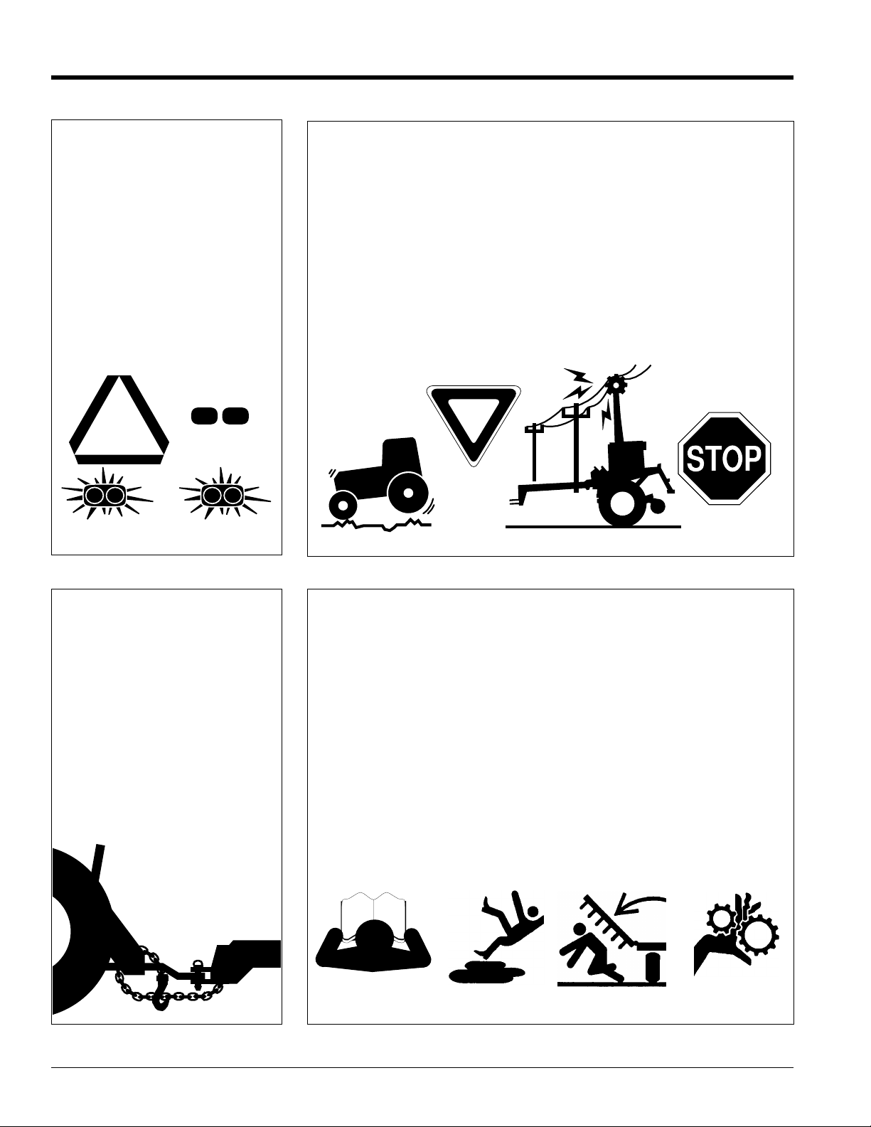
Use Safety
Lights and Devices
▲ Slow moving tractors, self-
propelled equipment, and towed
implements can create a hazard
when driven on public roads. They
are difficult to see, especially at
night.
▲ Flashing warning lights and turn
signals are recommended
whenever driving on public roads.
Use lights and devices provided
with implement.
Transport
Machinery Safely
▲ Comply with state and local laws.
▲ Maximum transport speed for
implement is 20 mph. DO NOT
EXCEED.Never travel at a speed
which does not allow adequate
control of steering and stopping.
Some rough terrain require a
slower speed.
▲ Sudden braking can cause a
towed load to swerve and upset.
Reduce speed if towed load is not
equipped with brakes.
▲ Use the following maximum
speed - tow load weight ratios as
a guideline:
20 mph when weight is less
than or equal to the weight of
tractor.
10 mph when weight is double
the weight of tractor.
IMPORTANT: Do not tow a load that
is more than double the weight of
tractor.
Use A Safety Chain
▲ A safety chain will help control
drawn machinery should it
separate from the tractor
drawbar.
▲ Use a chain with the strength
rating equal to or greater than
the gross weight of the towed
machinery.
▲ Attach the chain to the tractor
drawbar support or other
specified anchor location. Allow
only enough slack in the chain to
permit turning.
▲ Do not use safety chain for
towing.
Practice Safe Maintenance
▲ Understand procedure before
doing work. Use proper tools and
equipment, refer to Operator’s
Manual for additional information.
▲ Work in a clean dry area.
▲ Lower the implement to the
ground, put tractor in park, turnoff
engine, and remove key before
performing maintenance.
▲ Allow implement to cool
completely.
▲ Do not grease or oil implement
while it is in operation.
▲ Inspect all parts. Make sure parts
are in good condition & installed
properly.
▲ Remove buildup of grease, oil or
debris.
▲ Remove all tools and unused
parts from implement before
RCP2560 & RCPM2560 Series Parallel Arm Rotary Cutter 316-057M
2
4/28/08
Page 5

Land Pride
Important Safety Information
Table of Contents
Prepare for Emergencies
▲ Be prepared if a fire starts.
▲ Keep a first aid kit and fire
extinguisher handy.
▲ Keep emergency numbers for
doctor, ambulance, hospital and
fire department near phone.
911
Wear
Protective Equipment
▲ Protectiveclothing and equipment
should be worn.
▲ Wear clothing and equipment
appropriate for the job. Avoid
loose fitting clothing.
▲ Prolonged exposure to loud noise
can cause hearing impairment or
hearing loss. Wear suitable
hearing protection such as
earmuffs or earplugs.
▲ Operating equipment safely
requires the full attention of the
operator. Avoid wearing radio
headphones while operating
machinery.
Avoid High
Pressure Fluids Hazard
▲ Escaping fluid underpressurecan
penetratetheskincausingserious
injury.
▲ Avoid the hazard by relieving
pressure before disconnecting
hydraulic lines or performing work
on the system.
▲ Make sure all hydraulic fluid
connections are tight and all
hydraulic hoses and lines are in
good condition before applying
pressure to the system.
▲ Use a piece of paper or
cardboard, NOT BODYPARTS, to
check for suspected leaks.
▲ Wear protective gloves and safety
glasses or goggles when working
with hydraulic systems.
▲ If an accident occurs, see a
doctor immediately. Any fluid
injected into the skin must be
treated within a few hours or
gangrene may result.
Keep Riders
Off Machinery
▲ Riders obstruct the operator’s
view, they could be struck by
foreign objects or thrown from the
machine.
▲ Never allow children to operate
equipment.
4/28/08
RCP2560 & RCPM2560 Series Parallel Arm Rotary Cutter 316-057M
3
Page 6
Important Safety Information
Table of Contents
Land Pride
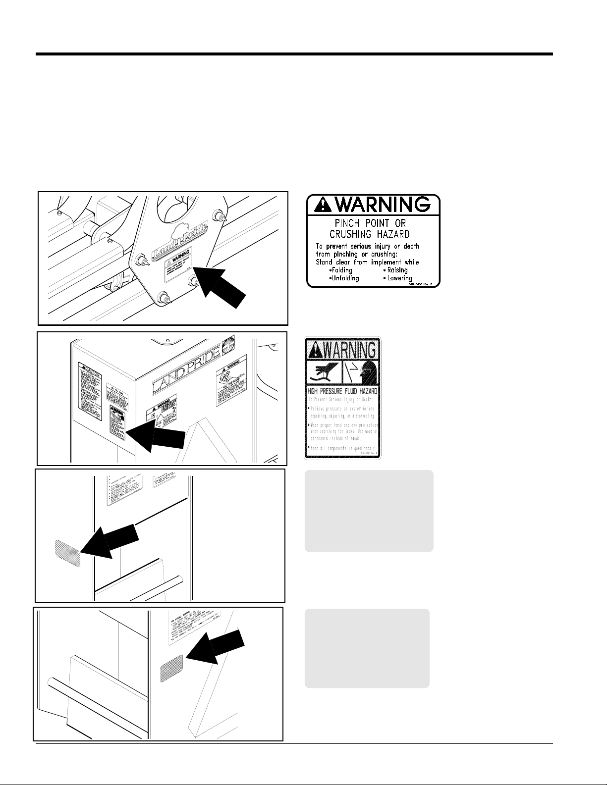
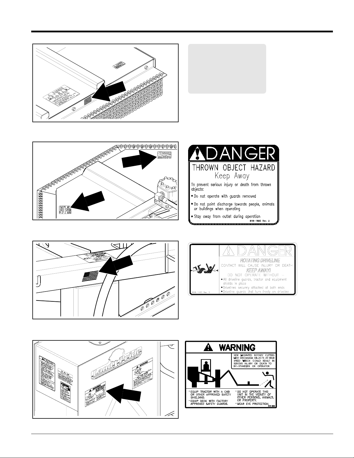
Safety Labels
Your cutter comes equipped with all safety labels in place. They
were designed to help you safely operate your implement. Read
and follow their directions.
1. Keep all safety labels clean and legible.
2. Replace all damaged or missing labels. To order new
labels go to your nearest Land Pride dealer.
3. Some new equipment installed during repair requires
safety labels to be affixed to the replaced component as
specified by Land Pride. When ordering new components
12326
make sure the correct safety labels are included in the
request.
4. Refer to this section for proper label placement.
To install new labels:
a. Clean the area the label is to be placed.
b. Spray soapy water on the surface where the label is to
be placed.
c. Peel backing from label.Press firmly onto the surface.
d. Squeeze out air bubbles with the edge of a credit card.
818-045C
Warning - Pinch Point Hazard
12121
818-339C
Warning - High
Pressure Fluid
Hazard
818-229C
Amber Reflectors
12319
RCP2560 & RCPM2560 Series Parallel Arm Rotary Cutter 316-057M
4
818-230C
Red Reflector
12320
4/28/08
Page 7
Land Pride
Important Safety Information
Table of Contents
818-230C
Red Reflector
12429
818-180C
Danger Thrown Object
Hazard Keep
Away!
12322
12323
818-142C
Danger - Rotating Driveline Hazard
818-390C
Warning Thrown Object
Hazard
12321
4/28/08
RCP2560 & RCPM2560 Series Parallel Arm Rotary Cutter 316-057M
5
Page 8
Important Safety Information
12222
Table of Contents
Land Pride
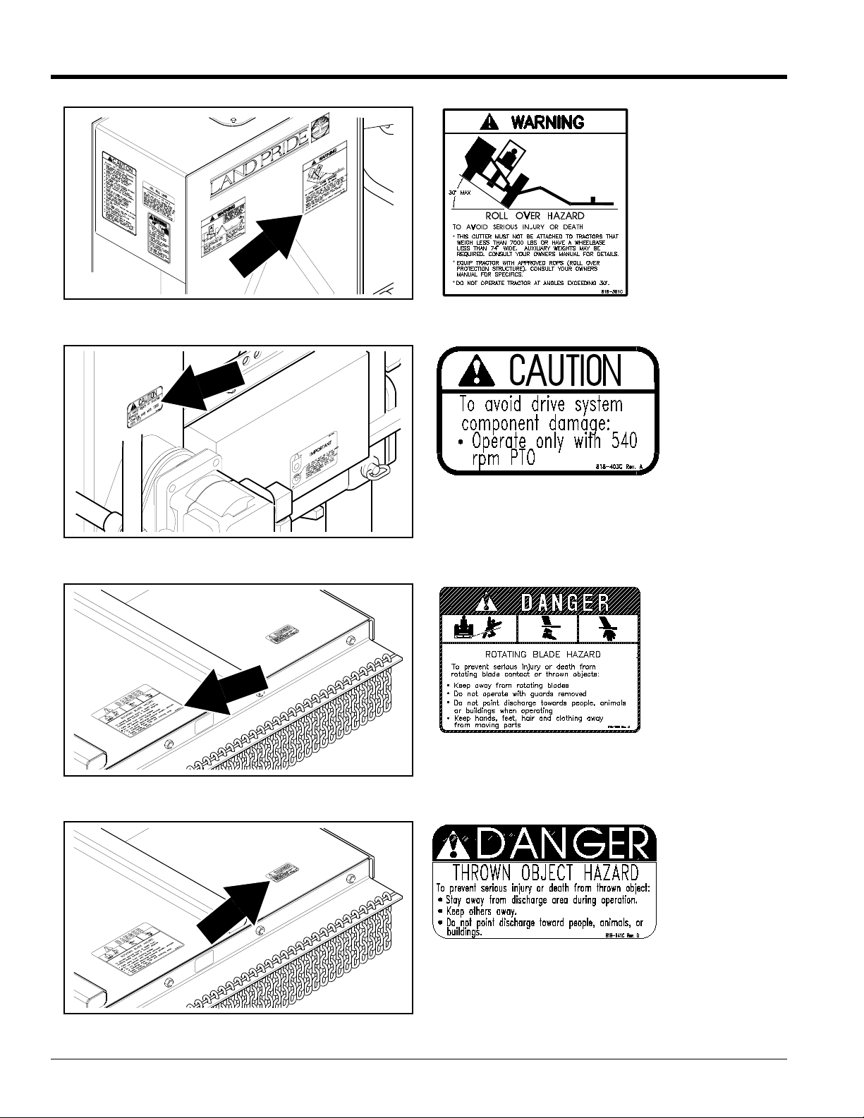
818-391C
Warning - Tractor
Roll Over Hazard
12324
12325
818-403C
(Used on 540 rpm PTO only)
Caution - 540 RPM PTO
818-186C
Danger - Keep Away Rotating Blade Hazard
RCP2560 & RCPM2560 Series Parallel Arm Rotary Cutter 316-057M
6
12325
818-141C
Danger - Thrown Object Hazard
4/28/08
Page 9
Land Pride
Important Safety Information
12222
Table of Contents
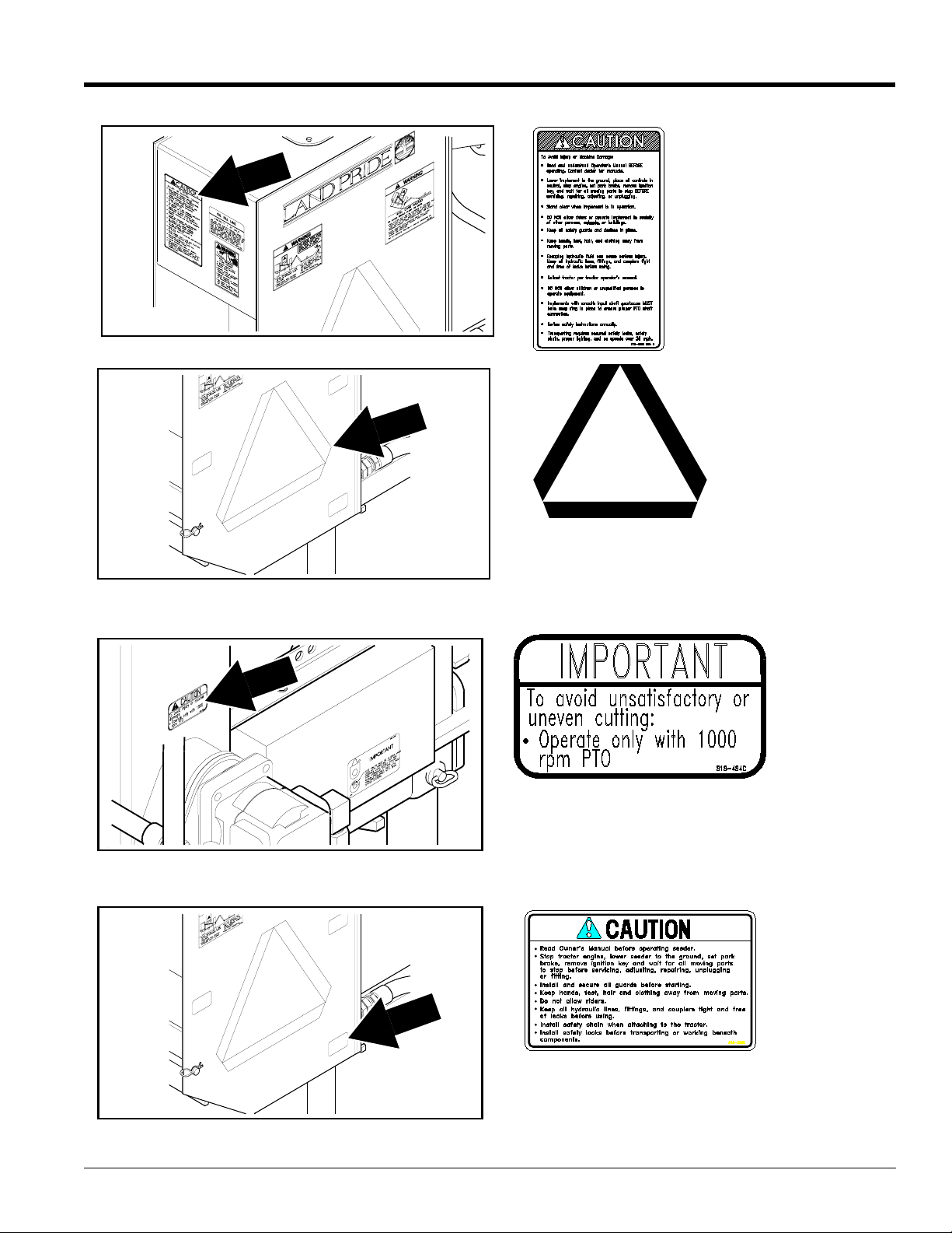
818-350C
Caution - General
Safety Information
13568
12324
818-003C
Slow Moving Vehicle Emblem
818-484C
(Used on 1000 rpm PTO only)
Important - 1000 rpm PTO
4/28/08
13568
RCP2560 & RCPM2560 Series Parallel Arm Rotary Cutter 316-057M
818-338C
Caution! General Safety Information
7
Page 10
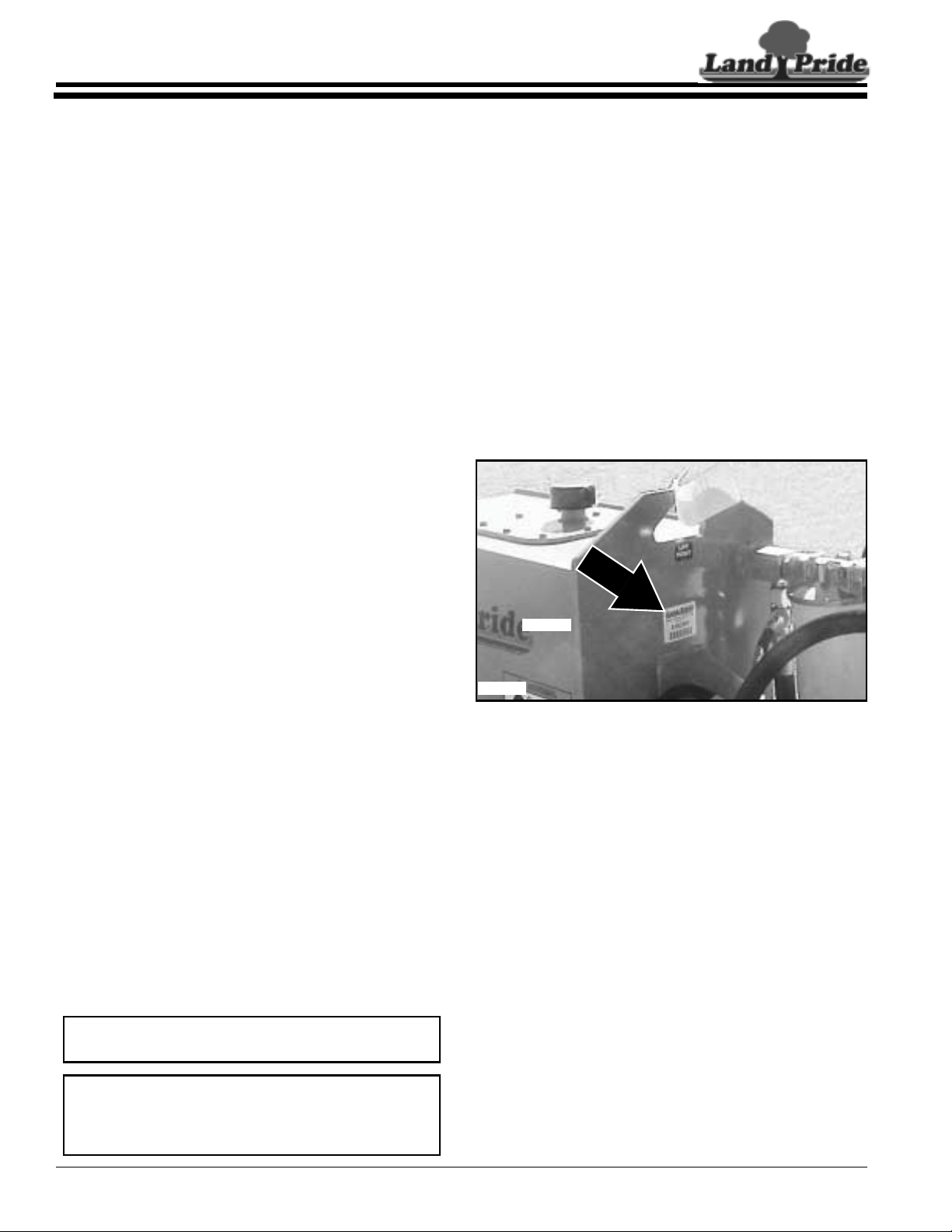
Table of Contents
Section 1: Introduction
Section 1: Introduction
Land Pride welcomes you to the growing family of new
product owners.
This Cutter has been designed with care and built by
skilledworkersusingqualitymaterials.Properassembly,
maintenance, and safe operating practices will help you
get years of satisfactory use from the machine.
Application
The RCP2560 Series Hydraulic Parallel Arm Rotary
Cutters are designed and built by Land Pride to provide
excellentcuttingperformanceonditchbanksandsloping
areas adjacent to right-of-ways, lakes, ponds and
streams. They are designed to work equally as well in
and around areas of restricted access such as over or
under fences, guardrails, low overhanging branches,
tree limbs, and hedges. These units perform extremely
well in tall grass cutting applications and will easily cut
through standing brush up to two inches in diameter.
The RCP2560 series is adapted for Category 2 or 3
three-point hitch mounting on 75 to 150 hp. tractors
weighing 7000 lbs. or more. Pump and reservoir system
require either 540 or 1000 input rpm. Cutter drive and
tractor will need to be equipped with, depending upon
operator configuration, one to four hydraulic outlets to
operate the cutters lift/extension/rotation arm.
SeeSection8:Specifications&Capacities on page 31for
additional information and performance enhancing
options.
Using This Manual
•
This Operator’s Manual is designed to help familiarize
you with safety, assembly, operation, adjustments,
troubleshooting, and maintenance. Read this manual
and follow the recommendations to help ensure safe
and efficient operation.
• The information contained within this manual was
current at the time of printing. Some parts may change
slightly to assure you of the best performance.
• To order a new Operator’s or Parts Manual contact
your authorized dealer. Manuals can also be
downloaded, free-of-charge from our website at
www.landpride.com or printed from the Land Pride
Service & Support Center by your dealer.
Terminology
“Right” or “Left” as used in this manual is determined by
facing the direction the machine will operate while in use
unless otherwise stated.
Definitions
Land Pride
Owner Assistance
The Warranty Registration card should be filled out by
the dealer at the time of purchase. This information is
necessary to provide you with quality customer service.
If customer service or repair parts are required contact a
LandPridedealer. A dealer has trained personnel, repair
parts and equipment needed to service the cutter.
The parts on your cutter have been specially designed
and should only be replaced with genuine Land Pride
parts. Therefore, should your cutter require replacement
parts go to your Land Pride Dealer.
Serial Number Plate
For prompt service always use the serial number and
modelnumber when ordering partsfrom your Land Pride
dealer.Besuretoincludeyourserialandmodel numbers
incorrespondencealso. Refer to Figure 1forthe location
of your serial number plate.
22008
22008
Serial Number Plate Location
Figure 1
Further Assistance
Your dealer wants you to be satisfied with your new
cutter.Ifforanyreasonyoudonotunderstand any part of
thismanual or are not satisfied with theservice received,
the following actions are suggested:
1. Discuss the matter with your dealership ser vice
manager making sure he is aware of any problems
youmay haveand that he has had the opportunity to
assist you.
2. If you are still not satisfied, seek out the owner or
general manager of the dealership, explain the
problem and request assistance.
3. For further assistance write to:
NOTE: A special point of information that the
operator must be aware of before continuing.
IMPORTANT: A special point of information related
to its preceding topic. Land Pride’s intention is that
this information should be read and noted before
continuing.
RCP2560 & RCPM2560 Series Parallel Arm Rotary Cutter 316-057M
8
Land Pride Service Department
1525 East North Street
P.O. Box 5060
Salina, Ks. 67402-5060
E-mail address
lpservicedept@landpride.com
4/28/08
Page 11
Land Pride
Section 2: Assembly & Set-up
Section 2: Assembly & Set-up
Table of Contents
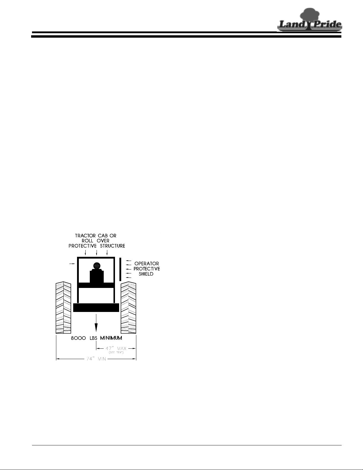
Tractor Requirements
The Parallel Arm Cutter, by design, must be used only
on tractors that are capable of controlling the cutter
under all operatingconditions. When the arms are fully
extended, a right-hand torque load on the tractor is
present which will try to tip the tractor over! The tractor
MUST have a minimum weight of 7000 lbs. A 3-Point
Category II or Category III hitch with hydraulic lift
control is required.
As shown in Figure 2-1, the rear wheel base must be
not less than 74" wide asmeasured from the outside of
each tire. If the right-hand tractor tire is more than 47"
from the center of the tractor, it may interfere with the
hydraulic motor on the deck when it is in the transport
position. If the tractor is equipped with dual wheels, the
right-hand dual may have to be removed.
A single, tractor duplex hydraulic outlet is required if
the cutter is equipped with the optional Electric
Cylinder Control. Three duplex hydraulic outlets will be
needed for parallel arm and deck control if the cutter is
NOT equipped with the optional Electric Cylinder
Control.
Anadditionaltractor,duplexhydraulicoutletisrequired
if the cutter is equipped with the optional hydraulic
breakaway cylinder.
A tractor Power Take-Off (PTO) is required for pump/
motoroperation. This cutteris available witheither 540
rpmor 1000 rpm rated PTO speed increasers.For best
fuel economy, it is recommended that the 540 rpm unit
be used on 1000 rpm tractors. However, PTO output
RPM must be carefully controlled (by engine RPM)
such that the PTO speed does not exceed 540 RPM.
The actual horsepower required for pump/motor
operation is approximately 30 HP.
If the tractor weight is less than 8500 lbs, auxiliary
counterbalance weights will be required. These
weights can be added to the weight bracket of the
hydraulic reservoir or (preferably) to the left-hand
tractor wheel.
The reservoir weight bracket is designed to be used
with conventional John Deere type suitcase weights each weight being 100 lbs. A total of 8 weights can be
added to the bracket.
ThetractorMUSTbeequippedwithoperatorprotective
equipment in the form of shielding from thrown objects
andRollOverProtectiveStructure(ROPS)asshownin
Figure 2-1.
A universal operator protective shield is available from
Great Plains Mfg. Refer to page 16 for more
information and installation.
It is also recommended that protective shielding or
screen be added to the right hand side of the tractor
engine cowling and radiator. This will help protect the
tractor finish and radiator against thrown objects.
The lower 3-Point links of the 3-Point hitch must be
stabilized to prevent side-to-side movement. Most
tractors have sway blocks or adjustable chains for this
purpose.
4/28/08
Minimum Tractor Requirements
Figure 2-1
12250
RCP2560 & RCPM2560 Series Parallel Arm Rotary Cutter 316-057M
9
Page 12

Section 2: Assembly & Set-up
Table of Contents
Land Pride
Dealer Preparations
This cutter has been assembled at the factory. Some
preparation will be necessary to attach the cutter to the
customer’s tractor. Ensure that the intended tractor
conforms to the requirements stated under the heading
“Tractor Requirements” on page 9.
IMPORTANT: Hydraulic fluid must be added to the
hydraulic reservoir before this unit is placed into
operation. Do not attempt to run the pump without
fluid or damage to the pump will occur.
3-Point Hookup
Prepare the cutter as follows:
1. Locate the cutter on a flat and level concrete
surface.
2. For proper hitch configuration determine the hitch
category for the tractor being used.
(Refer to Figure 2-2 on page 11)
Preparation Checklist
3. Back the tractor into position and connect the
3-Point hitch ar ms and top link. Start the tractor,
thenslowly raise the 3-Point hitch about 1-2". Stow
the jack stands in the raised position.
Check to be sure that the deck safety chain is in
place.
Slowlyoperate thetractor's3-Pointhydraulic control
up and down and check for clearance between the
tires, reservoir, frame, drawbar etc.
Ensure that the lower arms are blocked to prevent
excessive side movement. Adjust the tractor's
Lower lift arms to level the cutter from left to right.
Adjustthe top-link so thatthecutterisapproximately
level from front to rear. A final adjustment will be
made later.
Before operating this unit, 80-90 EP Gear Lube must be added to the gearbox & motor as indicated in the
maintenance lubrication section (page 27) of this manual.
35 Gallons of Hydraulic Fluid for the hydraulic reservoir. Use any high quality mineral based hydraulic fluid such as
Mobil Fluid 424 with a viscosity rating of 10W-30.
Additional hydraulic fluid (approx 2 gallons) for the tractor reservoir.
Miscellaneous assembly tools: hammer, tape measure, hacksaw, assortment of wrenches and sockets,1/4" drill/drill
bits,
spirit level.
Quick disconnect adaptors to match your tractors duplex outlets. Quantities required depend on options selected:
(2) If equipped with Electric Cylinder Control Option
(6) If not equipped with Electric Switching Option
(2) If equipped with hydraulic Breakaway Cylinder Option
Possible need for forklift or hoist capable of lifting 2500 lbs.
Auxiliary tractor weights (depending on tractor size).
A minimum of two people available during assembly.
If a pin, bolt or other part has been removed, and you are unsure where it is used, use the parts section of this
manual to identify it. Be sure the part gets used in the correct location. By double checking while you assemble, you
will lessen the chance of using a bolt incorrectly that may be needed later.
Safety decals are legible and undamaged from shipment.
PTO shaft and loose parts bag/box shipped with the cutter.
RCP2560 & RCPM2560 Series Parallel Arm Rotary Cutter 316-057M
10
4/28/08
Page 13

Land Pride
Section 2: Assembly & Set-up
Table of Contents
Category III
Standard & Quick Hitch
Category II
Quick Hitch
Category II
Standard Hitch
4/28/08
12251
Hitch Category
Figure 2-2
RCP2560 & RCPM2560 Series Parallel Arm Rotary Cutter 316-057M
11
Page 14

Section 2: Assembly & Set-up
Table of Contents
Land Pride
PTO Hookup
IMPORTANT: Do not engage tractor PTO until
driveline is fully connected and hydraulic fluid has
been added to the cutter reservoir.
IMPORTANT: A quick hitch may be used, but is not
recommended because it moves the cutter deck
back about 5" and impedes operator visibility.
IMPORTANT: See Figure 1-4 below. Avoid
premature PTO dr iveline breakdown. PTO driveline
mustnot exceedanangle of 25 degrees upordown
while operating cutter.
Maximum PTO driveline Movement
Figure 1-4
b. Set tractor in park, shut tractor engine off, set park
brake and remove switch key.
c. Pull driveline apart into two sections as shown in
Figure1-5.Attach outer driveline universal joint to
the tractor PTO shaft. Attach inner driveline
universaljoint to the Rotary Cutter gearbox shaft.
Pull on each drivelinesection to be sure universal
joints are secured to the shafts.
d. Hold driveline sections parallel to each other to
determine if theyaretoolong. The inner and outer
shieldsoneach section should end approximately
1" short of reaching the universal joint shield on
the adjacent section (see “B” dimension). If they
are too long, measure 1" (“B” dimension) back
from the universal joint shieldand make a mark at
this location on the inner and outer driveline
shields.
e. Cut off inner shield at mark (“X” dimension). Cut
same amount off inner shaft (“X1” dimension).
Repeat cut off procedure (“Y”&“Y1” dimensions)
to outer driveline half.
f. Remove all burrs and cuttings.
13800
IMPORTANT: Always check driveline minimum
length during initial setup, when connecting to a
differenttractorand when alternatingbetweenusing
aquickhitch and a standard3-point hitch. More than
one driveline may be required to fit all applications.
IMPORTANT: Itisnecessary to aligningthe tractor’s
PTO shaft level with the Rotary Cutter’s gearbox
shaft when checking driveline minimum length. Too
long a driveline can damage tractor, gearbox and
driveline.
Check Driveline Minimum Length
Refer to Figure 1-5
1. Start tractor and slowly engage 3-point controls to
move lower arms until the Rotary Cutter’s gearbox
shaft is approximately level with tractor's PTO shaft.
2. Slide inner yoke of the driveline over the cutter’s
gearbox shaft and secure with locking collar.
3. Slide outer yoke end of driveline over tractor PTO
shaft and secure with locking collar. Skip to step 5 on
page 12 if driveline fits between tractor and Rotary
Cutter.
4. Thedrivelinewillrequireshorteningifitis too long to fit
between tractor and Rotary Cutter. Shorten driveline
as follows:
a. Raise/lower 3-point lower arms until Rotary Cutter
and tractor PTO shafts are approximately level
with each other. Securely support cutter frame in
this position with blocking.
Shortening PTO Driveline Shields and Shafts
Figure 1-5
5. Apply multi-purpose grease to the inside of the outer
driveline shaft and reassemble the two shafts.
6. Attach inner driveline yoke to the cutter gearbox input
shaft.
7. Attach outer driveline yoke to the tractor's PTO shaft.
8. The driveline should now be moved back and forth to
insure that both ends are secured to the tractor and
Rotary Cutter PTO shafts. Reattach any end that is
loose.
IMPORTANT: Two small chains supplied with the
driveline must be attached to restrict dr iveline shield
rotation.
9. Hookoneofthedrivelinesafetychains in a hole on the
outeryokeshieldand the opposite end to the tractor to
restrict outer shield rotation.
10. Hook second driveline safety chain in a hole on the
inner yoke shield and opposite end to the Rotary
Cutter frame to restrict inner shield rotation.
RCP2560 & RCPM2560 Series Parallel Arm Rotary Cutter 316-057M
12
4/28/08
Page 15
Land Pride
Table of Contents
Section 2: Assembly & Set-up
11. Start tractor and raise cutter just enough to remove
support blocks used in step 4a on page 12.
12. Slowly engage tractor’s hydraulic 3-point controls to
raise and lower the cutter. Check drawbar clearance.
Move or remove drawbar as needed.
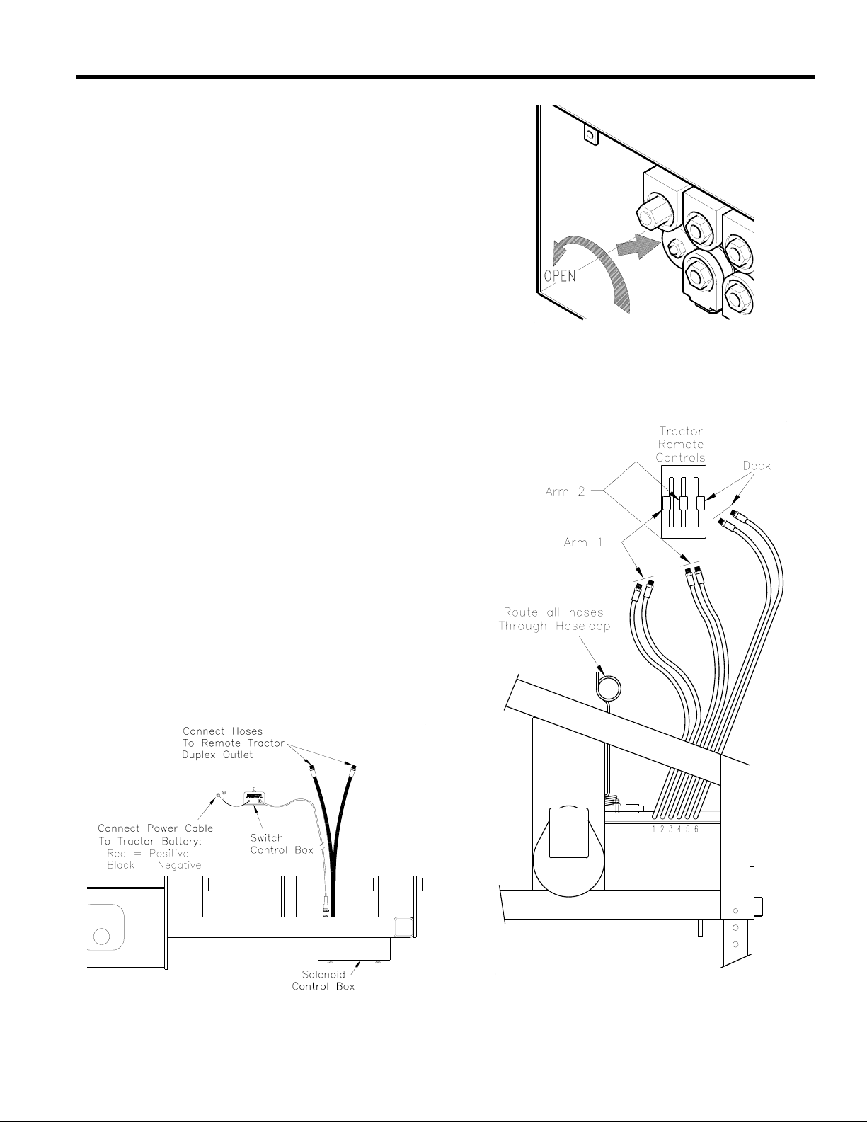
Hydraulic Hookup
1. Connect the hydraulic hoses to the tractor duplex
outlet(s). “Pioneer” quick disconnect hose couplings
are supplied with each hose. Some tractors use
other types of quick couplers.
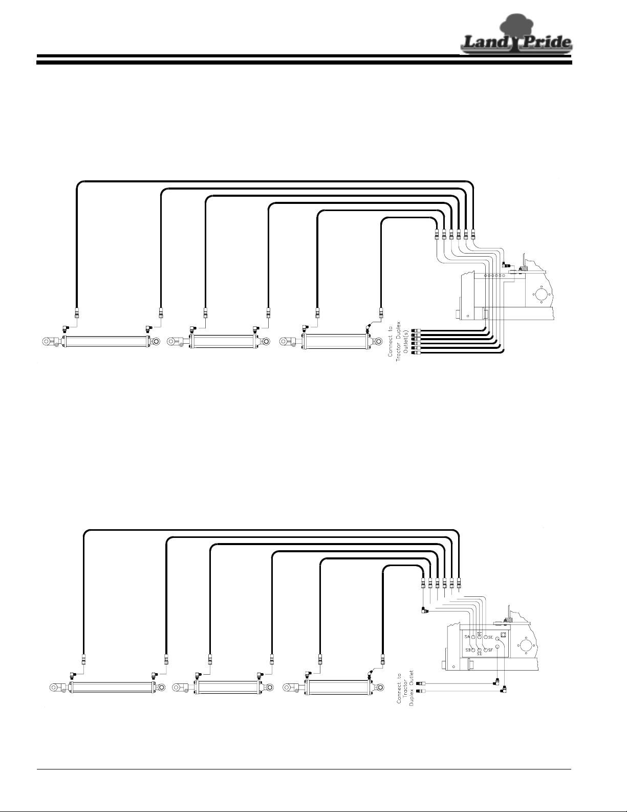
a. See Figure 2-4: If the cutter is equipped with the
optional electric cylinder control, two hoses from
the solenoid valve control box will be attached to
a single duplex outlet on the tractor.
See Figure 2-5: You must determine if the tractor
being used is configured for “OPEN” or
“CLOSED” center hydraulic flow. Consult the
tractor operator's manual if unsure. Remove the
access cover located at the rear of the solenoid
valve control box to adjust the flow control valve.
If the tractor is OPEN center, the valve must be
open(turnknob counterclockwise). If the tractor is
CLOSED center, the valve must be closed (turn
knob clockwise).
b. See Figure 2-6: If the cutter is NOTequippedwith
the optional Electric Cylinder Control, six hoses
(2 per cylinder) will be connected to 3 duplex
outlets on your tractor. Each tractor duplex outlet
must be capable of infinite, variable flow control
by the operator and should have center detent
(off) levers. A typical tractor setup is shown in
Figure 2-6. The hoses on each outlet should be
connected such that when the control lever is
pushed“forward”,thearm (or deck)extends.If the
levers operate in reverse, simply reverse the
hoses at the duplex receptacle.
12374
12255
Flow Control Valve Knob
Figure 2-5
Optional Electrical Control Hook-Up (S/N 163695-)
Figure 2-4
4/28/08
12253
Hose Hookup Without Electric Cylinder Control Option
Figure 2-6
RCP2560 & RCPM2560 Series Parallel Arm Rotary Cutter 316-057M
13
Page 16

Table of Contents
Section 2: Assembly & Set-up
c. See Figure 2-7: If the cutter is equipped with the
optionalbreakawaycylinder,twoadditionalhoses
will be connected toa single duplexoutleton your
tractor.
12256
Breakaway Cylinder Hose Connections
Figure 2-7
2. Add 35 gallons of hydraulic fluid to the hydraulic
reservoir. Use any high quality mineral based
hydraulicfluid such asMobilfluid424 with a viscosity
rating of 10W-30. Use care to ensure that dust or
otherforeignparticles do notcontaminatethe fluid or
reservoir. Check the fluid level by inserting the
dipstick and cap all the way into the filler tube.
Electrical Hookup
NOTE: If the tractor has dual 6 volt batteries, see
the tractors owners manual for proper 12 volt
hook-up.
Land Pride
12257
Electric Switch Control Box
Figure 2-8
Mount the Switch Control Box using either sheet metal
screws (for plastic type consoles) or machine screws,
nutsand washer. Routethe control cableto the Solenoid
Control Box and connect the circular plastic connector to
the mating connector on the box.
See Figure 2-4 on page 13.Route the power cable to the
tractor battery or circuit breaker panel. A 10 Amp or
larger fuse/circuit breaker source should be used.
Connect the red lead to the positive power source.
Connect the black lead to the negative source.
IMPORTANT: Connect leads to 12VDC power
source only. Connection to 24VDC or larger will
damage electrohydraulic components.
Ensure that the 10 Amp circuit breaker located on the
switch control box is pushed in prior to functional check.
IMPORTANT: This section only applies to Unitswith
Solenoid Control Valve Option.
Determine if tractor is “OPEN” or “CLOSED” Center
HydraulicSystem. If unsure consultyour tractors owners
manual and/or contact your tractor dealer.
IMPORTANT: All dual 6 volt batteries are not
hooked up correctly cylinders may not function
properly due to solenoid valves not being fully
charged. Arm and deck functions will be slow.
See Figure 2-8: Find a suitable location for the Switch
Control Box. Based on our experience, the location
should be close to the right hand side of the operator most generally on the tractor fender or fender console.
Exact location should be convenient to the specific
operator. Orient the Control Box such that the switches
are relative to the movement of the deck and parallel
arms. I.e., when the switch is toggled, the arms or deck
should move in the same relative direction as the handle
of the switch.
RCP2560 & RCPM2560 Series Parallel Arm Rotary Cutter 316-057M
14
12443
Deck Safety Chain
Figure 2-9
4/28/08
Page 17
Land Pride
Section 2: Assembly & Set-up
Table of Contents
Functional Check
1. Removethe decksafety chain from thelatch position
and place the loose end on the stowage hook
provided.SeeFigure 2-9. Startthetractorandadjust
the 3-point hitch until the PTO shaft is approximately
level.
2. Cycle the parallel arm and deck cylinders for proper
operation.
!
Hydraulic fluid under pressure can penetrate skin. Wear
protective gloves and safety glasses or goggles when working
with hydraulic systems. Use a piece of cardboard or wood
rather than hands when searching for hydraulic leaks. If
hydraulic fluid is injected into the skin, it must be treated by a
doctor within a few hours or gangrene may result.
DANGER
NOTE: The following procedure assumes that the
cutter is equipped with the optional Electric Cylinder
Control. Go to step “c” if your cutter is not equipped
with this option.
a. In Step 1.a. (Hydraulic Hookup), two hoses from
the Solenoid Control Valve were connected to a
single duplex outlet on the tractor. If the tractor is
equipped with more than one remote duplex
outlet, you must first determine which console
lever is used to control this outlet. The control
lever must then be locked into the “Automatic
Extend Position” or the “Automatic Retract
Position”.
b. Toggle the switch on the control box labeled
“ARM1” by pushing it forward (away from you).
The inboard parallel arm should extend outward.
If it does not move, or moves in the opposite
direction (retracts), you should either change the
position of the console lever (from retract to
extend or vice-versa) or reverse the hoses at the
duplex outlet. Toggle the ARM1 switch by pulling
back on it. The inboard parallel arm should
retract. See Figure 2-10.
Repeat this procedure for the remaining arm and
deck cylinders. Cycle all of the cylinders to full
extension and retraction to remove any air that
might be trapped in the system.
Check the hydraulic fluid level in your tractor's
reservoir. If low, add fluid to the system before
proceeding. The cylinders and hoses will require
approximately 1 3/4 gallons from the tractor.
NOTE: Thefollowing procedure is for those cutters
that are not equipped with the Electric Cylinder
Control.
c. Operate the tractor console control lever
designated for “ARM1” by pushing it forward. The
inboard arm should extend outward. If the arm
tries to retract, reverse the hoses at the duplex
outlet. See Figure 2-10.
Repeat this procedure for the remaining arm and
deck cylinders. Cycle all of the cylinders to full
extension and retraction to purge any air that
might be trapped in the system.
12254
4/28/08
Parallel Arm Movement
Figure 2-10
RCP2560 & RCPM2560 Series Parallel Arm Rotary Cutter 316-057M
15
Page 18
Section 2: Assembly & Set-up
Table of Contents
Land Pride
Check the hydraulic fluid level in your tractor's
reservoir. If low, add fluid to the system before
proceeding. The cylinders and hoses will require
approximately 1 3/4 gallons from the tractor.
d. Move the tractor and cutter to a remote location
(awayfrom all other persons) to check pump/
motor operation. Check to be sure the Hydraulic
Reservoir shut-off valve is full OPEN. If this
service valve is turned off, damage will occur to
the pump.
Position the cutter deck flat on the ground or
concrete surface. SLOWLY engage the PTO to
start blade rotation. On initial start-up, blade
position may cause the deck to “vibrate”. After 23 revolutions, these vibrations should stop. If the
deck continues to vibrate, shut off the PTO, raise
the deck and check for locked blades.
Gradually increase engine RPM until PTO output
RPM is 540. The deck should not exhibit
excessive vibration.
IMPORTANT: If the tractor being used is equipped
with a 1000 RPM PTO output, be sure that throttle
RPM is reduced to limit PTO output to 540 RPM.
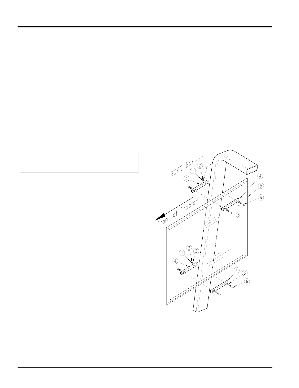
Carefullyremove the shieldfrom the shipping carton and
temporarily position it on the inside surface of the ROPS
bar. Locate the shield forward/back, up/down to provide
the best overall coverage for the tractor operator. Use a
spirit level to level the shield before marking. Mark the
top frame location with a pencil on each side of the
ROPS bar, and mark the vertical ROPS location on the
frame of the shield.
Position the shield (#5) on a flat work surface. Locate
one of the 316-116D (#4) flatbars next to the pencil
marks to determine which set of holes will clear the
vertical marks for the ROPS location. Mark the hole
location and drill two 1/4" diameter holes through the
frameofthe shield. Similarly mark and drilltwoadditional
holes for the lower clamp location.
Attach the shield to the inside surface of the ROPS bar
using the mounting hardware provided (#1), (#2), (#3),
and (#6).
Operator Protective Shield
Anoptional operator protective shieldis available for use
on tractors not equipped with cabs or other protective
shielding. This shield isa "universal" type andis suitable
for attachment to a conventional Roll Over Protective
Structure (ROPS) bar that is already attached to the
tractor. The shield is constructed of an extruded
aluminum frame and is glazed with 1/4" clear, lexan
polycarbonate.
Mounting hardware will permit attachment to ROPS
having cross-section dimensions of 2" x 4", 2" x 5", and
2" x 6" or 2 1/2" x 4", 2 1/2" x5 and 2 1/2" x6. Other sizes
may require longer mounting bolts and/or custom
flatbars. Installation requires that 4 mounting holes be
drilled in the frame of theshield. No modification is made
to the ROPS.
Installation
Refer to Figure 2-11:
Measurethe width andthickness of the ROPS bar on the
tractorto determine that theclamping hardware supplied
will be adequate.
Compare the parts list on and quantities with the parts
received. Report any missing or damaged items to your
dealer.
To determine the best location for the shield, the cutter
should be connected to the tractor. The parallel arms
should be fully extended and the deck should be
horizontal (or approximately level).
13239
Operator Protective Shield
Figure 2-11
RCP2560 & RCPM2560 Series Parallel Arm Rotary Cutter 316-057M
16
4/28/08
Page 19

Land Pride
Section 2: Assembly & Set-up
Table of Contents
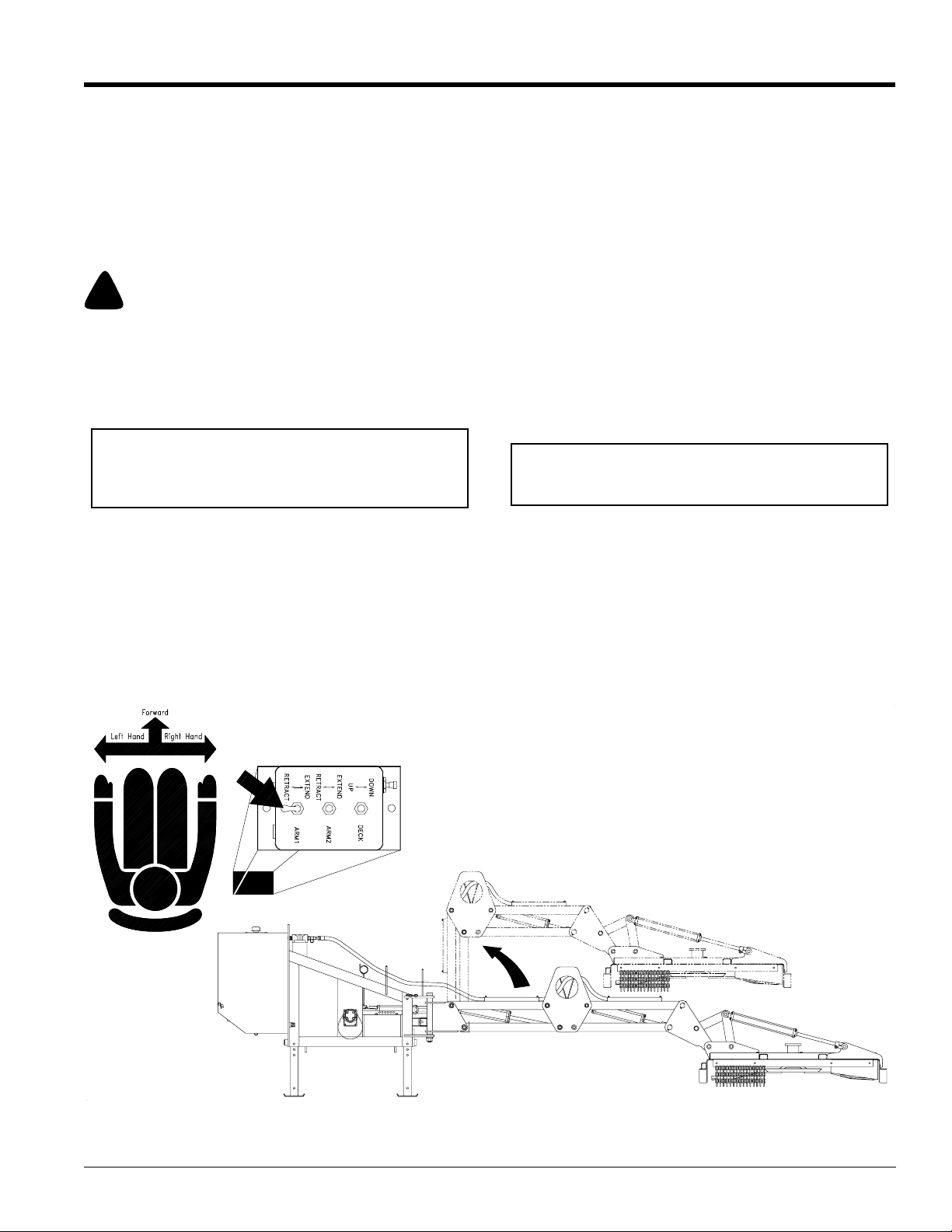
Setting Flow Control Valve
This procedure is for those units with the solenoid valve
option, on RCP 2560 and RCPM2560.
NOTE: Parallel Arm Cutters with (S/N 163695-) will
require flow control valve kit #316-068K if your
tractor does not have flow control (turtle/rabbit
control) or if your tractor uses an open center
hydraulic system. Check your tractor’s operator’s
manual to determine your tractor’s set-up.
The flow control valve diverts excess oil back to the
tractor, which in turn keeps the back pressure down and
keeps the oil cooler.
IMPORTANT: Overheatingof the oil may occur if the flow
control kit is not installed. Damage to the o-ring in the
solenoid valve and/or the cylinders may occur if the oil
becomes overheated
1. Time the 2nd arm cylinder (arm furthest from the
tractor) from the fully extended position, to the fully
retracted position.
2. Set the tur tle/rabbit control on the tractor,or the flow
control valve (optional), so that the cylinder cycles at
5 seconds.
3. These cylinders require 5 GPM (gallons per minute)
for proper ar m function. Timing of the cylinder is the
easiest way to set the GPM.
.
Timing Procedures
Refer to Figure 2-12:
1. Set the RCP2560 in the transport position with the
arms and deck in the folded position.
2. Retract the 2nd cylinder which will raise the 2nd
arms up. Time this sequence. Time should be 5
seconds.
3. Adjust the turtle/rabbit control or the flow control
valve until the cycle time is 5 seconds.
4. The unit is now set for proper operation.
If the unit is having overheating problems through the
hydraulics, check the tractor’s operator’s manual for
power beyond hook-up.
4/28/08
Timing Procedures
Figure 2-12
RCP2560 & RCPM2560 Series Parallel Arm Rotary Cutter 316-057M
14739
17
Page 20
Section 3: Hydraulics
Section 3: Hydraulics
Table of Contents
Land Pride
Hydraulic Cylinder Plumbing
The standard Parallel Arm Cutter is equipped with
three (3) remote cylinders to operate the parallel arms
and the cutter deck. These cylinders are connected
12260
Remote Cylinder Plumbing
Figure 3-1
directly to the tractor's remote duplex outlets and
controlled by the tractor operator. Each cylinder
requires a single duplex outlet on the tractor. See
Figure 3-1.
An optional electric cylinder control provides for
toggle switch operation of each cylinder. Response
time is much faster than with tractor controls and this
option is recommended where frequent changes are
12261
Remote Cylinder Plumbing
(Optional Electric Cylinder Control)
Figure 3-2
necessary because of terrain or cutting conditions.
Ditches and embankments are typical examples. The
electriccylindercontroloptioncan be easily added as a
field installation kit. See Figure 3-2.
RCP2560 & RCPM2560 Series Parallel Arm Rotary Cutter 316-057M
18
4/28/08
Page 21
Land Pride
Section 3: Hydraulics
Table of Contents
The hydraulic pump/motor circuit is shown in
Figure 3-3. It operates via a tractor driven PTO and is
notconnectedtotractorhydraulics. The pump receives
fluid from a 35 gallon reservoir. If the cutter blades are
stalled, an overpressure relief valve opens to provide a
return path to the reservoir.
12262
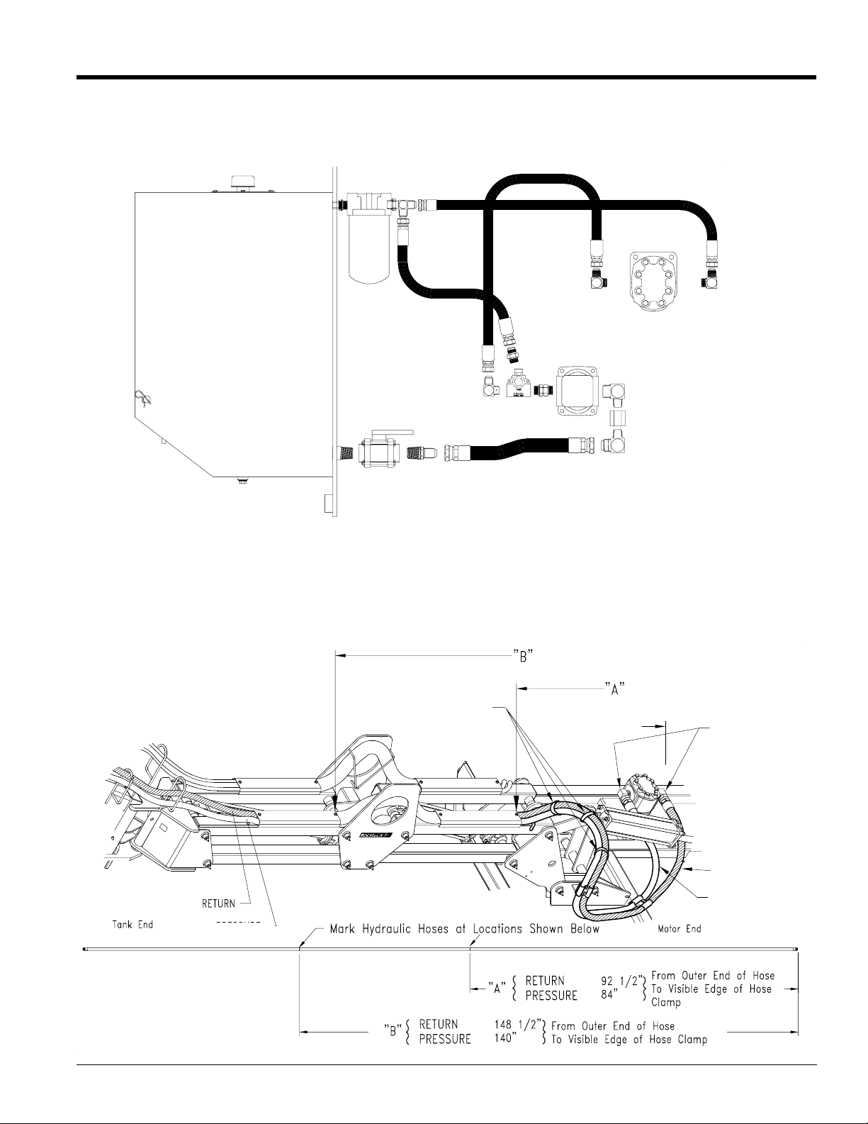
Marking Hydraulic Line Lengths
Hydraulic lines are marked to length from motor to
pump and pump to motor as outlined in Figure 3-4
below.
Hose Locations for Hydraulic
Pump and Motor
Figure 3-4
Hydraulic Pump Motor Circuit
Figure 3-3
Tie Strap
Outer End
*Orient 811-411C
Hyd. Fittings so they
are 45˚ down
towards deck
Return Line
Pressure Line
Pressure Line
**Twist return hose (811-404C) counterclockwise until it follows the same
contour as pressure hose
(811-403C).
13776
4/28/08
RCP2560 & RCPM2560 Series Parallel Arm Rotary Cutter 316-057M
19
Page 22

Section 3: Hydraulics
Table of Contents
Land Pride
The breakaway cylinder or tension bolt is used to
prevent structural damage to the cutter head and
parallelarms. If the cutter head strikes anobject during
forward movement, the breakaway cylinder extends allowing the cutter head and parallel arms to pivot 90
degrees to the rear. This movement is identical to that
of the tension bolt, but the big advantage of the
breakaway cylinder is that it can be easily reset using
the tractor's remote cylinder control levers.
The breakaway cylinder should be installed on the
cutter as shown in Figure 3-5. Be sure that the rod end
of the cylinder is located on the pivot lug as shown.
Connect both hoses from the cylinder to a remote
outlet on the tractor. The tension bolt should never be
used in conjunction with the breakaway cylinder.
The breakaway cylinder is designed to bypass
hydraulic fluid under high pressure when the cutter
head or parallel arms strike an object during forward
movement. Do not use any standard hydraulic cylinder
for a breakaway cylinder or damage could occur to the
unit.
NOTE: All units equipped with the breakaway
cylinderalso have a 1/2"tension bolt installed onthe
breakaway plates for shipping purposes. This bolt
must be removed after the cutter is hooked up to the
tractor.
12231
RCP2560 & RCPM2560 Series Parallel Arm Rotary Cutter 316-057M
20
Breakaway Cylinder Installation
Figure 3-5
4/28/08
Page 23
Land Pride
Section 3: Hydraulics
Table of Contents
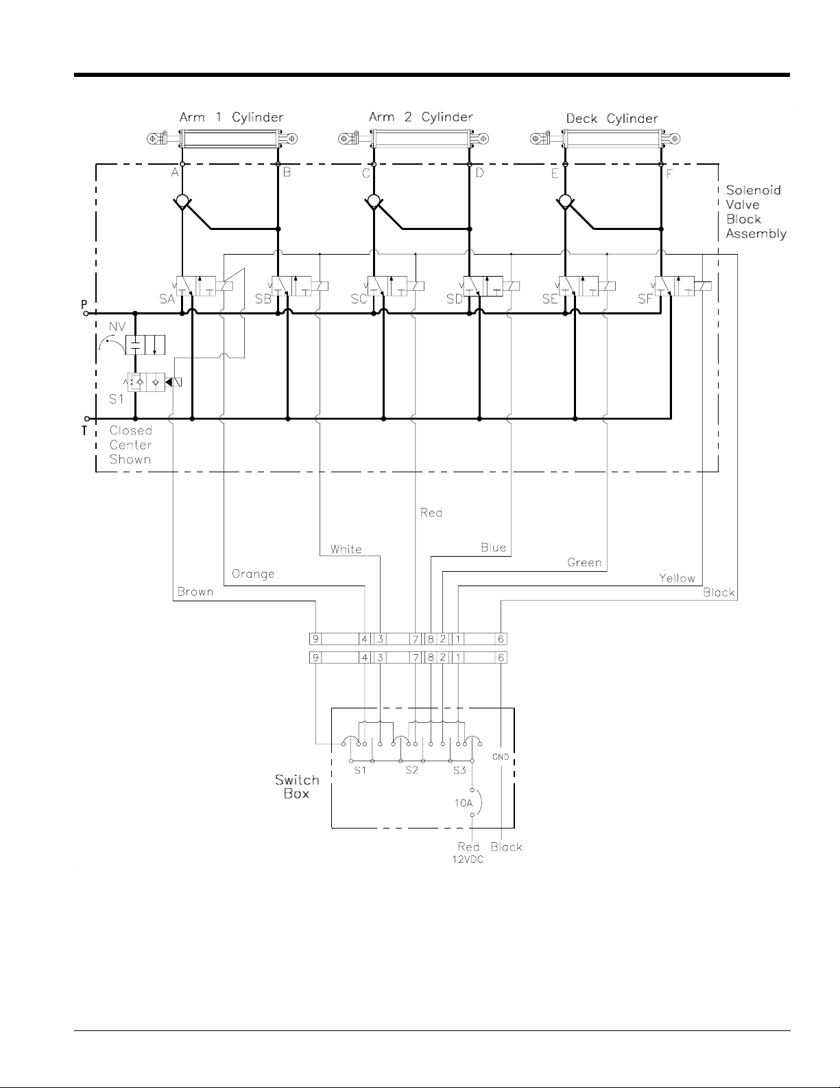
4/28/08
12263
Electric Cylinder Control Schematic (Optional)
Figure 3-6
RCP2560 & RCPM2560 Series Parallel Arm Rotary Cutter 316-057M
21
Page 24

Section 4: Adjustments
Section 4: Adjustments
Table of Contents
Land Pride
Deck Level Adjustments
The cutter deck should be adjusted for level attitude.
Adjust the cutter head deck cylinder (using the tractor
or optional electric cylinder control) so that the deck is
approximately level from left to right.
5. Raise the 3-Point hitch until the PTOshaft is
approximatelylevel.Extend the parallel ar ms tofull
length.
6. Place a level on the cutter deck to read forward/aft
attitude.
7. Adjust the 3-Point top link so that the front of the
cutter deck is slightly lower than the rear
(approximately 1/2"). See Figure 4-1
Deck level Adjustments
RCP2560 & RCPM2560 Series Parallel Arm Rotary Cutter 316-057M
22
12264
Figure 4-1
4/28/08
Page 25
Land Pride
Table of Contents
Section 5: Transporting
Section 5: Transporting
!
When traveling on public roads, whether at night or during
the day, use accessory lights and devices for adequate
warning to operator’s of other vehicles. Comply with all
federal, state and local laws.
Always disengage tractor PTO before transporting cutter to
avoid injury from thrown objects or blade contact.
8. Retract both parallel armsand position the deck to
CAUTION
!
CAUTION
vertical with thebladesfacingoutboard (awayfrom
the tractor).
9. Engagethe transpor t safetychainto the deck hook
(Figure 5-1).
10. Raise the 3-Point hitch up to provide 8-12" of
clearance for the deck.
!
The cutter is 10’-6" wide and care should be taken when
encountering oncoming traffic and roadside obstructions. If
in doubt about safe clearance, reduce speed and/or stop until
it is safe to proceed.
CAUTION
4/28/08
Transport Safety Chain
Figure 5-1
RCP2560 & RCPM2560 Series Parallel Arm Rotary Cutter 316-057M
12265
23
Page 26
Section 6: Operating Procedures
Section 6: Operating Procedures
Table of Contents
Land Pride
!
WARNING
The following operating procedures must be carefully read
and fully understood. You are the tractor operator and are
therefore responsible for the safe operation of this unit. All
other persons must be cleared of the area. Cutter operation
must be stopped when in the vicinity of other persons.
11. After attachment to the tractor, carefully raise and
lower the cutter to ensure that the drawbar, tires,
and other equipment on the tractor do not contact
the cutter frame or PTO shaft.
12. Check all hoses and wires to be sure that they will
not contact the PTO shaft. PTO guards must be in
good condition and in place.
13. When the deck is in the transport position, and the
PTO disengaged, check to be sure the blades are
not locked (overlapped) together. The deck safety
chain must be engaged in the deck hook provided.
14. Check blades for sharpness and ensure that both
blade bolts as well as the center blade carrier hub
nut are tight. Check tractor safety equipment particularly the ROPS (Roll Over Protective
Structure) and the operator safety screen to be
sureboth are in goodworking condition. Wear your
safety glasses.
15. Removeand stow the deck safetychainjustpriorto
cutting. Adjust lower 3-point links such that the
PTO shaft is approximately level. Extend the
cutters parallel arms out and position the deck flat
on the ground.
16. Increase tractor throttle to approximately 500 RPM
and slowly engage the PTO. Initial start-up
vibration is normal, but should stop after a few
revolutions of the blade carrier. If vibration
continues, stop PTO rotation. Wait for the blade
carrier to come to a complete stop before
dismountingfromthetractor,thencheckthe blades
to be sure they are not locked together.
17. Once the cutter is running smooth increase tractor
throttle to provide for 540 PTO RPM.
IMPORTANT: If a 1000 RPM tractor PTO is being
used, engine RPM MUST be reduced to limit PTO
RPM to 540. Excessive engine speed will cause
damage to the speed increaser and other power
train components.
18. Position the cutter deck for best operator visibility.
This is normally with the arms extended to
approximately 3/4 of full extension. Adjust deck
attitude and height. Optimum ground speed will
depend on the density of the material being cut,
operatorawareness,and (in some cases) terrain.If
in doubt, reduce tractor ground speed to a
comfortable level.
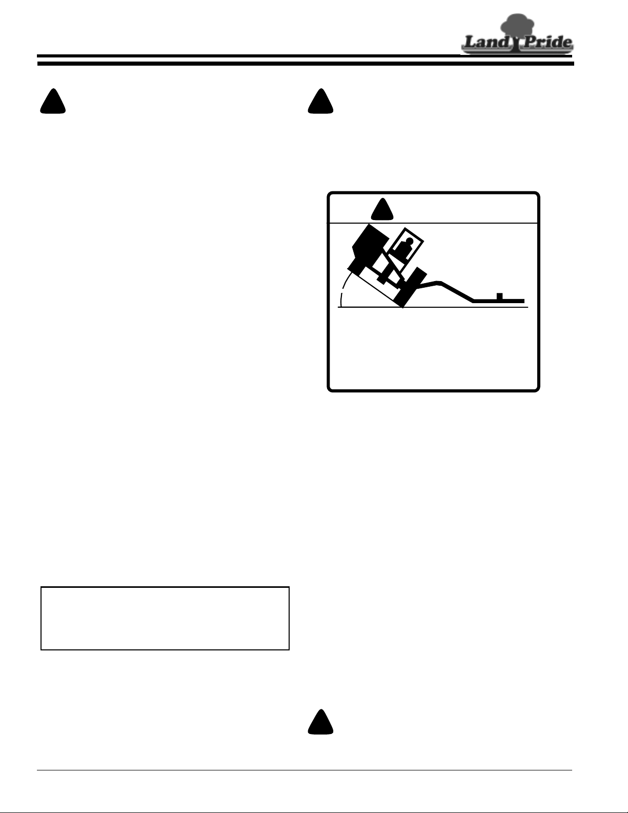
!
Do not operate this cutter under any terrain conditions that
would place the tractor at an angle exceeding 30 degrees
either front-to-rear or left-to-right. Ensure that adequate
ballast weights are provided on both the front of the tractor
and left of the tractor and left hand side of cutter to assure
tractor stability. See Figure 6-1.
WARNING
WARNING
!
30° MAX
TO AVOID SERIOUS INJURY OR DEATH
•THIS CUTTER MUST NOT BE ATTACHED TO TRACTORS THAT
REQUIRED. CONSULT YOUR OWNERS MANUAL FOR DETAILS.
ROLL OVER HAZARD
WEIGH LESS THAN 7000 LBS OR HAVE A WHEELBASE
LESS THAN 74" WIDE. AUXILIARY WEIGHTS MAY BE
•EQUIP TRACTOR WITH APPROVED ROPS (ROLL OVER
PROTECTION STRUCTURE). CONSULT YOUR OWNERS
MANUAL FOR SPECIFICS.
Maximum Tractor Angle
Figure 6-1
818-391C
Breakaway Operations
This cutter is designed for breakaway of the cutter
head and parallel arms in the event the cutter head
contacts an immovable object or irregular terrain
duringforward tractor movement. The“breakaway” will
prevent structural damage to the cutter head, parallel
arms, and mainframe in the event of such contact. See
Figure 6-2.
Upon breakaway, the cutter head must be reset to the
original "home" position before normal cutting
operations can be resumed. Reset to the home
position is accomplished somewhat differently
depending on whether the cutter is equipped with the
standard tension bolt or the optional breakaway
(hydraulic) cylinder.
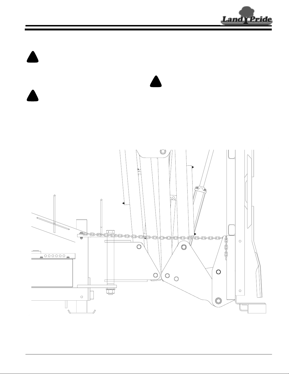
Tension Bolt
1. Raise the arms and deck upward to clear any
obstacles located behind the cutter deck.
2. Slowly back the tractor and cutter awayfrom those
obstacles that would interfere with rotating the
deck and arms back to the “home” position.
!
Shut off PTO power, put the tractor in park and wait for the
blades to stop rotating before dismounting from the tractor.
WARNING
RCP2560 & RCPM2560 Series Parallel Arm Rotary Cutter 316-057M
24
4/28/08
Page 27
Land Pride
Section 6: Operating Procedures
Table of Contents
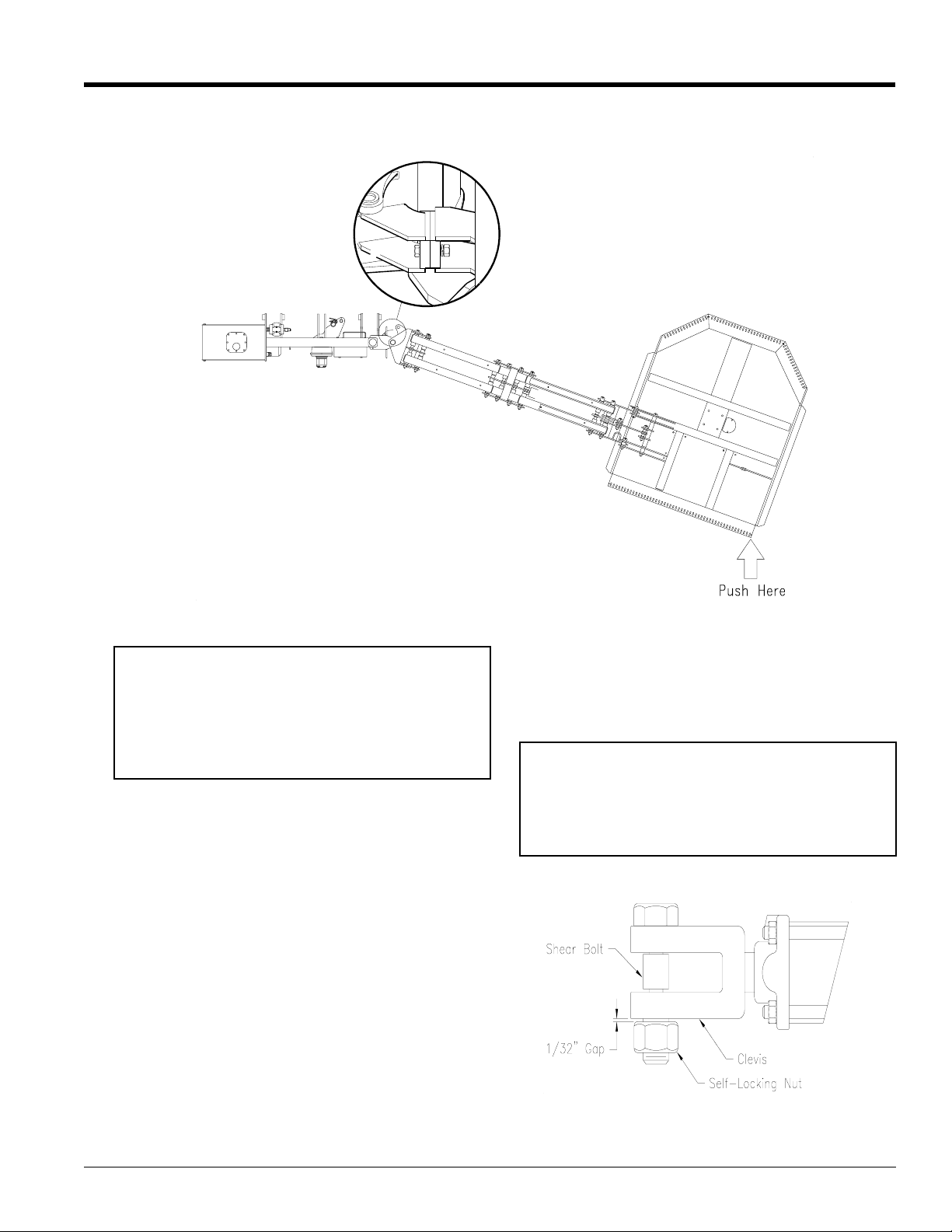
3. Push the deck forward until the breakaway plate
reaches the stop plate. See Figure 6-2. Replace
the tension bolt.
Breakaway Cylinder
1. Raise the arms and deck upward to clear any
obstacles located behind the cutter deck.
2. Slowly back the tractor and cutter awayfrom those
obstacles that would interfere with rotating the
deck and arms to the “home” position.
3. Use the tractor’sremote (cylinder) control to rotate
the deck/arms back to the “home” position.
IMPORTANT: Do not attempt to operate the
cutter in reverse. The breakaway mechanism will
function ONLY when the tractor is moving in a
forwarddirection. Cutter operation with the tractor in
reverse gear may cause structural damage to the
parallel arms if the cutter head strikes a solid or
immovable object.
A shear bolt is located at the rod end of the (optional)
breakaway cylinder. This bolt may shear under the
following conditions:
1. After breakaway, the operator backs the tractor
awayfrom the obstruction, but encounters an
additional obstruction or immovable object while
operating the tractor in reverse. Specifically, the
operator failed to raise the deck high enough to
clear the object before operating the tractor in
reverse.
2. The operator tried to reset the deck/arms by
backing the tractor into an obstruction rather than
using the tractor’s remote cylinder control.
3. The shear bolt has become fatigued after repeated
breakaway cycles and resets.
4. The self-locking nut used to hold the shear bolt in
place has been torqued to the point of contacting
the rod end of the cylinder and, because of
preloading causes the shear bolt to shear with
reduced effort.
IMPORTANT: Do not back the tractor to reset the deck
to “home” position. Doing so may cause severe
structural damage to the mainframe.
Breakaway Manual Reset
Figure 6-2
12267
In the event of shear bolt failure, the shear bolt MUST
be replaced with the correct replacement part (316118D). The use of a substitute part may result in
damage to the parallel arms or main frame. A single
replacement part is included with each cutter and is
located on a bracket adjacent to the upper 3-point
hitch.
IMPORTANT: Torque the self-locking nut onto the
shear bolt, but do not turn it so far as to make
contact with the clevis of the hydraulic cylinder. In
other words, the nut should be threaded onto the
shear bolt to within approximately 1/32" of contact
with the clevis. See Figure 6-3.
13403
Shear Bolt Space
Figure 6-3
4/28/08
RCP2560 & RCPM2560 Series Parallel Arm Rotary Cutter 316-057M
25
Page 28

Section 6: Operating Procedures
Table of Contents
Land Pride
General Operating Instructions
The RCP2560 Series Parallel Arm Hydraulic Rotary
Cutter is uniquely versatile and a powerfully productive
cutting implement in the hands of a skilled,
knowledgeable, and responsible operator. This unit is
frequently operated on inclines in populated areas and
near high traffic. Therefore, it is absolutely essential that
no one operates this cutter without first becoming totally
familiar with the Operator’s Manual. Make sure you pay
particular attention to Section 1 on Safety Rules, Section
2 on Assembly Instructions and Set-up, Section 5 on
Transporting, Section 6 on Operating Procedures, and
Section 7 on Maintenance and Lubrication.
You may put the Rotary Cutter to work once you have
carefully read and fully understood this Operator’s
manual. Transport to the work site at a safe speed and in
a manner that allows faster moving vehicles to pass
safely. A slow moving vehicle sign should always be
properly displayed when using public roads or right-of
ways. Upon arriving at the work site, shut-off the tractor,
set the brakes, remove ignition key, and dismount to
preform the following checks:
• Remove and safely store away deck safety chain.
• Verify thatthe PTO shaft is approximately level. Adjust
3-point link if PTO shaft is not level.
• Visually inspect cutter blades. Make certain they are
not overlapped and locked together.
Return to the tractor, after preforming the above checks,
to start the engine. Extend the cutter’s parallel arm out
and position the deck flat on the ground. Adjust height of
the parallel arm and cutting deck for good visibility and
unobstructed performance. Set engine RPM at idle or
slightly above and engage PTO. Initial start-up vibration
is normal and should smooth out after a few revolutions
of the cutter blades unless the blades are locked
together. Increase tractor throttle PTO speed to 540
RPM. Proceed forward at a mowing speed that is
comfortable and will produce a quality cut for ground
conditions and material density.
The RCP2560 Rotary Cutter is designed with an
automatic breakaway cutter head and parallel arm that
releases when the unit contacts immovable objects or
irregular terrain. The cutter head must be reset to “home
position”after each breakawaybefore cutting operations
can resume. See Section 6, page 24, “Breakaway
Operations” for additional information on resetting the
cutter head to “home position”.
See“Section8: Specifications & Capacities” onpage 31.
for additional information on performance enhancing
options.
It requires patience, practice, and attention to detail to
becomeanexpertoperator on your Land Pride RCP2560
Series Cutter, but the end result is well worth the effort.
RCP2560 & RCPM2560 Series Parallel Arm Rotary Cutter 316-057M
26
4/28/08
Page 29

Land Pride
Section 7: Maintenance & Lubrication
Section 7: Maintenance & Lubrication
Lubrication Points
Table of Contents
Lubrication
Legend
Multi-purpose
spray lube
12266
Multi-purpose
grease lube
Multi-purpose
oil lube
Parallel Arm Cutter Zerks
14Zerks
Type of Lubrication: Grease
50
50
Hours
8
Hours
Intervals in hours
at which lubrication
is required
12269
14294
PTO Zerks
2 Zerks
Type of Lubrication: Grease
20
Hours
Driveline Profiles
Type of Lubrication: Multi-purpose Grease
Quantity = Disconnect driveline from the tractor and slide
apart. Clean and coat the inner tube of the driveline with a
light film of grease, then reassemble.
4/28/08
RCP2560 & RCPM2560 Series Parallel Arm Rotary Cutter 316-057M
27
Page 30

Table of Contents
Section 7: Maintenance & Lubrication
Land Pride
The motor spindle hub housing (1), Figure 7-1 has two
cavityplugslocatedononesideof the housing just below
themotormounting flange. Position the cutter deckinthe
transport position and remove either plug to check fluid
level. Fluid level should be within 1/2" of the top of the
port. Add 80-90 weight gearlube as required. The
capacity of the cavity is approximately 1/3 pint.
13994
Motor/Spindle Hub
Figure 7-1
The hydraulic reservoir has an effective capacity of 35
gallons. A dipstick located on the filler cap indicates the
correct reservoir fluid level.
A filter mounted on the hydraulic reservoir is used to
clean the pump and motor system fluid. It should be
replaced after 2 years of service. A conventional 10
micron filter element should be used See Figure 7-2.
The speed increaser gearbox is mounted between the
PTO shaft and the hydraulic pump. It increases the
standard 540 RPM PTO speed to 2000 RPM at the
pump. The oil should be changed after the first 100
working hours. Successive changes should be made
after every 1500 hours or once a year. Use 80-90 weight
gearlube. Check the oil level by removing the level plug
located on the side of the case. Oil may be added by
removing the breather located at the top of the case. A
drain plug is located at the bottom of the case. See
Figure 7-3.
12270
Speed Increaser
Figure 7-3
Blade Servicing (Replacement)
The cutter blades should be inspected on a daily basis.
They must be kept sharp and should be replaced if they
are worn excessively.
Both blades should be sharpened at the same angle as
the original cutting edge and must be replaced or
reground at the same time to maintain proper balance
during rotation. Do not remove any more material than
necessary when sharpening blades.
12469
Filter Removal
Figure 7-2
RCP2560 & RCPM2560 Series Parallel Arm Rotary Cutter 316-057M
28
IMPORTANT: Replace blades with genuine Land
Pride blades only.If one blade is to be replaced, the
mating blade must also be replaced. Failureto do so
will result in an out-of-balance condition that will
contribute to premature bearing failure on the
spindle hub. Factory blades are 4" wide and 25"
When replacing or sharpening the cutter blades,
examine the blade bolts, shims and blade bolt nut.
Replace if necessary. Be sure that the blades are
installed properly. The airfoil (lift) must be oriented
towards the top of the deck. The blade bolt nuts must be
torqued to 450 ft-lbs.
4/28/08
Page 31

Land Pride
Section 7: Maintenance & Lubrication
Table of Contents
Blade Rotation
Figure 7-4
12271
Blade Rotation is clockwise. See Figure 7-4.
The Skid Shoes should be inspected at the beginning of
each cutting season. Original material thickness is 1/4".
They should be replaced when the material thickness is
less than 1/8" at any point. The skid shoes are
interchangeable from left to right.
Tractor Maintenance
IMPORTANT: One of the most important things you
can do to prevent hydraulic system problems is to
ensure that your tractor's reservoir remain free of
dirt and contamination. Use a clean cloth to wipethe
hose ends before attachment to your tractor.
Replace the filter element for your tractors hydraulic
systemattheprescribedintervals.Doingsowill go a long
way to prevent the occurrence of cartridge valve and
hydraulic cylinder problems on the Parallel Arm Cutter.
NOTE: Removal of the solenoid valves from the
valve block requires the removal of a 1/2" hex nut on
the end of the solenoid armature. Use care when
removing/replacing this nut. Use Locktite or other
thread locking compound when replacing and DO
NOTexert more than 3 ft lbs oftorque on this hexnut.
Remember that 3 ft lbs is slightly higher than finger
tight! See Figure 7-5. Overtightening this nut will
distort the hollow armature shaft and may result in
valve failure. See Solenoid Valve Block
12272
Solenoid Valve Block
Figure 7-5
Storage
At the end of the working season or when the cutter will
not be used for a long period, it is good practice to clean
off any dirt or grease that may have accumulated on the
cutter and any of the moving parts. It may be necessary
to scrape off compacted dirt from the bottom of the deck,
then use a garden hose to thoroughly clean the surface.
A coating of oil may also be applied to the lower deck
area to minimize oxidation.
Check the blades and blade bolts for wear and replace if
necessary. See “Section 7: Maintenance & Lubrication”
on page 27.
Inspect the cutter for loose, damaged or worn parts and
adjust or replace if needed.
Lubricate as noted in “Section 7: Maintenance &
Lubrication” on page 27.
Repaintpartswherepaint is worn or scratched to prevent
rust. Aerosol Buckskin touch-up paint is available from
your Land Pride Dealer. Order Land Pride part #821011C.
Store the cutter ina clean, dryplace. The deckshould be
positioned on a flat surface with the arms retracted and
the jack stands lowered to suitable 3-Point height.
Ensure that the main frame is stable. Use auxiliary
supportsorpostsifnecessary to prevent the possibility of
the unit tipping over.
4/28/08
RCP2560 & RCPM2560 Series Parallel Arm Rotary Cutter 316-057M
29
Page 32

Table of Contents
Section 7: Maintenance & Lubrication
Maintenance & Lubrication Record
Item to be Serviced When to Perform Reference Date
Land Pride
RCP2560 & RCPM2560 Series Parallel Arm Rotary Cutter 316-057M
30
4/28/08
Page 33

Land Pride
Table of Contents
Section 8: Specifications & Capacities
Section 8: Specifications & Capacities
RCP 2560 Parallel Arm Series
RCP2560
Cutting Width 58"
Overall Width (Fully Extended) 19’-8"
Transport Width 10’
Minimum Cutting Height (deck level) 2"
Maximum Horizontal Reach from Center of Tractor 186"
Maximum Vertical Reach (above horizontal) 137"
Maximum Vertical Reach (below horizontal) 109"
Deck Rotating Arc 180 degrees
PTO Input Speed 540 RPM
Rotor (motor) RPM (@ 540 PTO) 1000 RPM
Blade Tip Speed 15,000 FPM
Blade Size 1/2" x 4"
Blade Rotation Clockwise
Blade Bolt 1 1/2" with keyway; nut
Dishpan 3/16” X 21" Round, Dish Shaped
Cutting Capacity 2"
Deck Thickness 10 GA
Hydraulic Fluid Mobil 424
Hydraulic Reservoir Capacity 35 Gallons
Hydraulic Fluid Flow Rate 15 GPM (approx.)
Overload Protection Hydraulic Relief Valve
Driveline ASAE Category 2
Hitch 3-Point Cat. 2 & 3 with clevis style lower hitch, Quick hitch,
Minimum Tractor Weight 7000 Lbs.
Minimum Tractor Horsepower 75 HP
Skid Shoes 1/4" Reversible
Shipping Weight 1,930 Lbs (no fluid)
Options: Elect Cylinder Control
Breakaway Cylinder
Operator Safety Shield
1000 rpm Increaser / PTO
4/28/08
RCP2560 & RCPM2560 Series Parallel Arm Rotary Cutter 316-057M
31
Page 34

Table of Contents
Section 8: Specifications & Capacities
Land Pride
10703
Overall Dimensions
RCP2560 & RCPM2560 Series Parallel Arm Rotary Cutter 316-057M
32
Figure 9-1
4/28/08
Page 35

Land Pride
Table of Contents
Section 9: Troubleshooting
Section 9: Troubleshooting
Problem Cause Solution
Motor Oil Seal Leaking Returnline from motor has been pinched or
Spindle Hub Seal Leaking Return line from motor has been pinched or
PTO Shaft is bent. (NOTE: PTO
tractor hitch shaft should be
repaired or replaced if bent)
Blades wearing excessively Cutting on sandy ground Raise cutting height.
Blades coming loose Insufficient shimming Add shimming. See text.
Blades breaking Hitting solid objects Thoroughly check the cutting area
Loose Blade Carrier Worn Spindle Hub bearings. Replace Spindle Hub bearings and/or
Blade Carrier bent Hitting solid objects Avoid solid objects/Be alert.
Excessive skid shoe wear Cutting height not level or blade missing Adjust deck height or replace
Excessive vibration Locked blades Inspect and unlock blades.
Deck Cylinder will
not extend and/or retract
Deck Cylinder will not retract Cylinder rod is bent Replace cylinder.
Arm/Deck Cylinder(s) will not
extend and/or retract
Optional Electrical control
switch does not work
is collapsed
is collapsed
Contacting drawbar or Bottoming out Reposition drawbar/Replace PTO tubes
Contacting ground frequently Raise cutting height.
Blade bolts not tightened properly Torque blade bolt nuts to 450 ft lbs.
Shaft nut loose Tighten Spindle Hub shaft nut to
Soil abrasive Raisecuttingheight.
Cutting too low Raise cutting height.
Blades have unequal weight Replace blades as a PAIR.
PTO shaft bent Straighten or replace PTO shaft.
Blade carrier bent Replace/straightenbladecarrier.
PTO cross not centered with yoke Disassemble and inspect for incorrectly
Orifice elbow on rod end is plugged Clean orifice fitting.
Broken/disconnected wire on solenoid Check wiring on cartridge valve solenoids.
Electric solenoid valve is sticking/dirty. Remove solenoid valve and clean or
Circuit Breaker tripped Reset Breaker
Circular Plastic connector is not connected
to receptacle.
No power to switchbox connections. Check battery or power
Tractor spool valve not engaged (open). Lock tractor control valve open.
Flow Control Valve not adjusted properly
for open/closed center tractor
Hoses not connected to proper duplex
outlet on tractor
Defective solenoid on cartridge valve assy. Replace solenoid.
Solenoid Valves sticking. Remove/clean/replace solenoid valve.
Tractor hydraulic fluid level is too low. Add fluid to tractor reservoir.
Replace lower seal of motor. Check motor
return hose for kinks.
Replace lower seal of motor and Spindle
Hub output shaft seal. Check motor return
hose for kinks.
and cut to correct length.
BEFORE beginning to cut. Be alert during
cutting.
shaft.
450 ft lbs. minimum.
located needles or damaged bearing cap.
replace.
Connect remote cable to Solenoid Control
valve.
Adjust flow control valve
Connect hoses to proper tractor outlet.
4/28/08
RCP2560 & RCPM2560 Series Parallel Arm Rotary Cutter 316-057M
33
Page 36

Section 10: Appendix
Section 10: Appendix
Bolt Head Identification
Table of Contents
Torque Values Chart
Land Pride
Bolt Head Identification
Bolt Size
(Inches)
1
in-tpi
1/4" - 20 7.4 5.6 11 8 16 12 M 5 X 0.8 4 3 6 5 9 7
1/4" - 28 8.5 6 13 10 18 14 M 6 X 1 7 5 11 8 15 11
5/16" - 18 15 11 24 17 33 25 M 8 X 1.25 17 12 26 19 36 27
5/16" - 24 17 13 26 19 37 27 M 8 X 1 18 13 28 21 39 29
3/8" - 16 27 20 42 31 59 44 M10 X 1.5 33 24 52 39 72 53
3/8" - 24 31 22 47 35 67 49 M10 X 0.75 39 29 61 45 85 62
7/16" - 14 43 32 67 49 95 70 M12 X 1.75 58 42 91 67 125 93
7/16" - 20 49 36 75 55 105 78 M12 X 1.5 60 44 95 70 130 97
1/2" - 13 66 49 105 76 145 105 M12 X 1 90 66 105 77 145 105
1/2" - 20 75 55 115 85 165 120 M14 X 2 92 68 145 105 200 150
9/16" - 12 95 70 150 110 210 155 M14 X 1.5 99 73 155 115 l215 160
9/16" - 18 105 79 165 120 235 170 M16 X 2 145 105 225 165 315 230
5/8" - 11 130 97 205 150 285 210 M16 X 1.5 155 115 240 180 335 245
5/8" - 18 150 110 230 170 325 240 M18 X 2.5 195 145 310 230 405 300
3/4" - 10 235 170 360 265 510 375 M18 X 1.5 220 165 350 260 485 355
3/4" - 16 260 190 405 295 570 420 M20 X 2.5 280 205 440 325 610 450
7/8" - 9 225 165 585 430 820 605 M20 X 1.5 310 230 650 480 900 665
7/8" - 14 250 185 640 475 905 670 M24 X 3 480 355 760 560 1050 780
1" - 8 340 250 875 645 1230 910 M24 X 2 525 390 830 610 1150 845
1" - 12 370 275 955 705 1350 995 M30 X 3.5 960 705 1510 1120 2100 1550
1-1/8" - 7 480 355 1080 795 1750 1290 M30 X 2 1060 785 1680 1240 2320 1710
1 1/8" - 12 540 395 1210 890 1960 1440 M36 X 3.5 1730 1270 2650 1950 3660 2700
1 1/4" - 7 680 500 1520 1120 2460 1820 M36 X 2 1880 1380 2960 2190 4100 3220
1 1/4" - 12 750 555 1680 1240 2730 2010
1 3/8" - 6 890 655 1990 1470 3230 2380
1 3/8" - 12 1010 745 2270 1670 3680 2710
1 1/2" - 6 1180 870 2640 1950 4290 3160
1 1/2" - 12 1330 980 2970 2190 4820 3560
Torque tolerance + 0%, -15% of torquing values. Unless otherwise specified use torque values listed above.
Grade 2 Grade 5
Grade 8
N·m ft-lb3N · m ft-lb N · m ft-lb mm x pitch N · m ft-lb N · m ft-lb N · m ft-lb
Bolt Size
(Metric)
1
in-tpi = nominal thread diameter in inches-threads per in
2
N· m = newton-meters
3
ft-lb= foot pounds
4
mm x pitch = nominal thread diameter in millimeters x
thread pitch
5.8 8.8 10.9
Class 5.8 Class 8.8 Class 10.9
Additional Torque Values
Blade Bolt Lock Nut 450 ft-lbs.
Blade Carrier Hub Nut 450 ft-lbs. minimum
RCP2560 & RCPM2560 Series Parallel Arm Rotary Cutter 316-057M
34
4/28/08
Page 37

Land Pride
Section 10: Appendix
be free from defects in material and workmanship beginning on the date of
purchase by the end user according to the following schedule when used as
intended and under normal service and conditions for personal use.
and the installation by thedealer of any such replacementpart, and does not cover
common wear items such as blades, belts, tines, etc. Land Pride reservesthe right
to inspect any equipment or parts which are claimed to have been defective in
material or workmanship.
judgment shall have been misused or damaged by accident or lack of normal
maintenance or care, or which has been repaired or altered in a way which
adversely affects its performance or reliability, or which has been used for a
purpose for which the product is not designed. Misuse also specifically includes
failure to properly maintain oil levels, grease points, and driveline shafts.
the product and all warranty adjustments must be made through such dealer. Land
Pride reserves the right to make changes in materials or design of the product at
any time without notice.
of any kind, direct, consequential, or contingent to property. Furthermore, Land
Pride shall not be liable for damages resulting from any cause beyond its
reasonable control. This Warranty does not extend to loss of crops, any expense
or loss for labor, supplies, rental machinery or for any other reason.
with respect to this sale; and all implied warranties of merchantability and
fitness for a particular purpose which exceed the obligations set forth in this
written warranty are hereby disclaimed and excluded from this sale.
the date of purchase by the end user.
Table of Contents
Warranty
Land Pride warrants to the original purchaser that this Land Pride product will
Overall Unit and Driveline: One year Parts and Labor
Hydraulic Cylinder: One year Parts and Labor.
Hoses and seals are considered wear items.
Hydraulic Motor: Two years Parts and Labor.
Solenoid Control Valves: One year Parts and Labor.
This Warranty is limited to the replacement of any defective part by Land Pride
This Warranty does not apply to any part or product which in Land Pride’s
Claims under this Warranty must be made to the dealer which originally sold
This Warranty shall not be interpreted to render Land Pride liable for damages
No other warranty of any kind whatsoever, express or implied, is made
This Warranty is not valid unless registered with Land Pride within 30 days from
4/28/08
RCP2560 & RCPM2560 Series Parallel Arm Rotary Cutter 316-057M
35
Page 38

Corporate Office: P.O. Box 5060
Salina, Kansas 67402-5060 USA
www.landpride.com
 Loading...