

Page 1
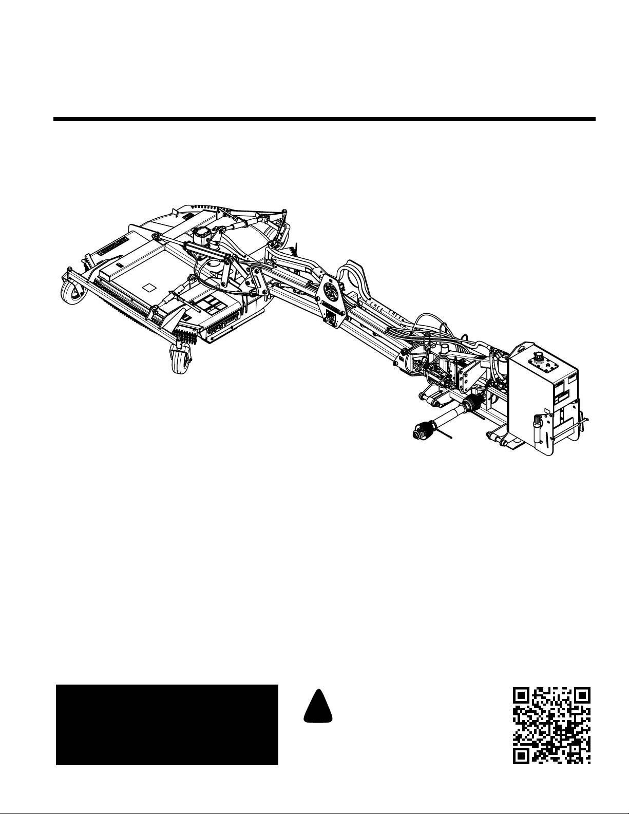
Table of Contents
Parallel Arm Rotary Cutter
RCP2660, RCPM2660, RCP3060 and RCPM3060
30028
Operator’s Manual
Read the Operator’sManual entirely.When you
see this symbol, the subsequent instructions and
warnings are serious - follow without exception.
!
Your life and the lives of others depend on it!
Coverphoto may show optional equipment
not supplied with standard unit.
© Copyright 2013 Printed
316-111M
1/11/13
Page 2

Table of Contents
Table of Contents
Important Safety Information . . . . . . . . . . . . . 1
Safety at All Times . . . . . . . . . . . . . . . . . . . . . . . . . 1
Safety Labels . . . . . . . . . . . . . . . . . . . . . . . . . . . . .4
Introduction . . . . . . . . . . . . . . . . . . . . . . . . . . 10
Application . . . . . . . . . . . . . . . . . . . . . . . . . . . . . . . 10
Using This Manual . . . . . . . . . . . . . . . . . . . . . . . . . 10
Owner Assistance . . . . . . . . . . . . . . . . . . . . . . . . . 10
Serial Number . . . . . . . . . . . . . . . . . . . . . . . . . . 10
Section 1: Assembly & Set-up . . . . . . . . . . . 12
Tractor Requirements . . . . . . . . . . . . . . . . . . . . . . 12
Protective Equipment Requirements . . . . . . . . . . . 13
Dealer Preparations . . . . . . . . . . . . . . . . . . . . . . . 13
Hooking-up the Rotary Cutter . . . . . . . . . . . . . . . . 14
Driveline Installation . . . . . . . . . . . . . . . . . . . . . . . 15
Check Driveline Collapsible Length . . . . . . . . . . 15
Shorten Driveline . . . . . . . . . . . . . . . . . . . . . . . . 16
Check Driveline Maximum Length . . . . . . . . . . . 16
Check Driveline Interference . . . . . . . . . . . . . . . 16
Hydraulic Reservoir Oil Fill . . . . . . . . . . . . . . . . . . 17
Transport Safety Chain . . . . . . . . . . . . . . . . . . . . . 17
Breakaway Cylinder . . . . . . . . . . . . . . . . . . . . . . . 17
Weight Hanger Assembly . . . . . . . . . . . . . . . . . . . 18
Gauge Wheels (Optional) . . . . . . . . . . . . . . . . . . . 18
Section 2: Hydraulic Set-up Options . . . . . . 19
Options . . . . . . . . . . . . . . . . . . . . . . . . . . . . . . . . . 19
Tractor Control . . . . . . . . . . . . . . . . . . . . . . . . . . . 19
Hydraulic Hose Hook-up . . . . . . . . . . . . . . . . . . 19
Console Control Lever Functional Checks . . . . . 20
Solenoid Control . . . . . . . . . . . . . . . . . . . . . . . . . . 21
Independent Control . . . . . . . . . . . . . . . . . . . . . . . 22
Solenoid Valve Block Functions . . . . . . . . . . . . . . 22
Independent Control . . . . . . . . . . . . . . . . . . . . . . 22
Solenoid Control . . . . . . . . . . . . . . . . . . . . . . . . . 22
Control Sticks . . . . . . . . . . . . . . . . . . . . . . . . . . . . 23
Control Stick Hook-up . . . . . . . . . . . . . . . . . . . . 24
Control Stick Operation . . . . . . . . . . . . . . . . . . . 25
Control Stick Functional Checks . . . . . . . . . . . . . 25
Section 3: Adjustments . . . . . . . . . . . . . . . . . 28
Hydraulic Flow Control . . . . . . . . . . . . . . . . . . . . . 28
Flow Control Valve on the Rotary Cutter . . . . . . 28
Turtle/Rabbit Flow Control at the Tractor . . . . . . 28
Deck Level Adjustments . . . . . . . . . . . . . . . . . . . . 29
Without Gauge Wheels . . . . . . . . . . . . . . . . . . . 29
With Gauge Wheels . . . . . . . . . . . . . . . . . . . . . . 29
Section 4: Operating Procedures . . . . . . . . . 30
Operating Checklist . . . . . . . . . . . . . . . . . . . . . . . . 30
Transporting . . . . . . . . . . . . . . . . . . . . . . . . . . . . . 30
Basic Operating Instructions . . . . . . . . . . . . . . . . . 31
Breakaway Instructions . . . . . . . . . . . . . . . . . . . . . 32
Shear Bolt Replacement . . . . . . . . . . . . . . . . . . 32
Un-hooking the Rotary Cutter . . . . . . . . . . . . . . . .32
General Operating Instructions . . . . . . . . . . . . . . .33
Section 5: Optional Equipment . . . . . . . . . . . 34
Parallel Arm Rotary Cutter Options . . . . . . . . . . . .34
Bolt-on Weight Hangers . . . . . . . . . . . . . . . . . . . . .35
Operator Protective Shield . . . . . . . . . . . . . . . . . . .36
Section 6: Hydraulic Plumbing . . . . . . . . . . . 37
Breakaway Cylinder . . . . . . . . . . . . . . . . . . . . . . . . 37
Pressure Shut Down Valve Operation . . . . . . . . 37
Tractor Control . . . . . . . . . . . . . . . . . . . . . . . . . . . .37
Solenoid Control . . . . . . . . . . . . . . . . . . . . . . . . . . 38
Solenoid Plumbing . . . . . . . . . . . . . . . . . . . . . . .38
Hydraulic Cylinder Plumbing . . . . . . . . . . . . . . . .38
Deck Motor Plumbing . . . . . . . . . . . . . . . . . . . . . 39
Independent Control . . . . . . . . . . . . . . . . . . . . . . .40
Cylinder Pump Plumbing . . . . . . . . . . . . . . . . . .40
Hydraulic Cylinder Plumbing . . . . . . . . . . . . . . . .40
Deck Motor Plumbing . . . . . . . . . . . . . . . . . . . . . 41
Section 7: Electrical Wiring Schematics . . . . 42
Solenoid Control Option . . . . . . . . . . . . . . . . . . . . .42
Wiring Schematic Without Gauge Wheels . . . . .42
Wiring Schematic With Gauge Wheels . . . . . . . .43
Independent Control Option . . . . . . . . . . . . . . . . . . 44
Wiring Schematic Without Gauge Wheels . . . . .44
Wiring Schematic With Gauge Wheels . . . . . . . .45
Section 8: Maintenance & Lubrication . . . . . 46
Maintenance . . . . . . . . . . . . . . . . . . . . . . . . . . . . . 46
Rotary Cutter Blades . . . . . . . . . . . . . . . . . . . . . . . 46
Skid Shoes . . . . . . . . . . . . . . . . . . . . . . . . . . . . . . 47
Solenoid Valve Block . . . . . . . . . . . . . . . . . . . . . . . 48
Hydraulic Hose Replacement . . . . . . . . . . . . . . . .48
Tractor Maintenance . . . . . . . . . . . . . . . . . . . . . . . 49
Storage . . . . . . . . . . . . . . . . . . . . . . . . . . . . . . . . .49
Lubrication Points . . . . . . . . . . . . . . . . . . . . . . . . . 50
Parallel Arm . . . . . . . . . . . . . . . . . . . . . . . . . . . . 50
Deck Pivot . . . . . . . . . . . . . . . . . . . . . . . . . . . . .50
Parallel Arm Pivot . . . . . . . . . . . . . . . . . . . . . . . .50
Driveline Yokes . . . . . . . . . . . . . . . . . . . . . . . . . 51
Driveline Profile . . . . . . . . . . . . . . . . . . . . . . . . . 51
Gauge Wheel Yoke and Wheel Bearing . . . . . . .51
Ratchet Jack . . . . . . . . . . . . . . . . . . . . . . . . . . . .51
Motor Spindle Hub . . . . . . . . . . . . . . . . . . . . . . . . .52
Hydraulic Reservoir . . . . . . . . . . . . . . . . . . . . . . . . 52
Speed Increaser . . . . . . . . . . . . . . . . . . . . . . . . . . 52
Section 9: Specifications & Capacities . . . . . 53
Section 10: Features & Benefits . . . . . . . . . . 55
Section 11: Troubleshooting . . . . . . . . . . . . . 56
Section 12: Torque Values Chart . . . . . . . . . . 58
Section 13: Warranty . . . . . . . . . . . . . . . . . . . 59
© Copyright 2013 All rights Reserved
Land Pride provides this publication “as is” without warranty of any kind, either expressed or implied. While every precaution has been taken in the
preparationof this manual,Land Pride assumesno responsibility forerrors oromissions. Neither isany liabilityassumedfor damagesresulting from theuse
oftheinformation contained herein. LandPridereservesthe right to reviseandimprove its productsasit sees fit. This publicationdescribes the state of this
product at the time of its publication, and may not reflect the product in the future.
Land Pride is a registered trademark.
All other brands and product names are trademarks or registered trademarks of their respective holders.
Printed in the United States of America.
RCP2660, RCPM2660, RCP3060 and RCPM3060 Parallel Arm Rotary Cutter 316-111M
1/11/13
Page 3
▲
Table of Contents
Important Safety Information
Important Safety Information
These are common practices that may or may not be applicable to the products described in
this manual.
Safety at All Times
Thoroughly read and understand
the instructions given in this
manual before operation. Refer to
the “Safety Label” section, read all
instructions noted on them.
Do not allowanyoneto operate this
equipment who has not fully read
and comprehended this manual
and who has not been properly
trained in the safe operation of the
equipment.
▲ Operator should be familiar with all
functions of the unit.
▲ Operate implement from the
driver’s seat only.
▲ The operator must not use drugs
or alcohol as they can change the
alertness or coordination of that
person while operating equipment.
The operator should, if taking overthe-counter drugs, seek medical
advice on whether he or she can
safely operate the equipment.
▲ Make sure all guards and shields
are in place and secured before
operating implement.
▲ Do not leave tractor or implement
unattended with engine running.
▲ Dismounting from a moving tractor
could cause serious injury or
death.
▲ Do not allow anyone to stand
between tractor and implement
while backing up to implement.
▲ Keep hands, feet, and clothing
away from power-driven parts.
▲ Wear snug fitting clothing to avoid
entanglement with moving parts.
▲ Watch out for wires, trees, etc.,
when raising implement. Make
sure all persons are clear of
working area.
▲ Turningtractor too tight may cause
implement to ride up on wheels.
This could result in injury or
equipment damage.
▲ Do not carry passengers on
implement at any time.
Look For The Safety Alert Symbol
The SAFETY ALERT SYMBOL indicates there is a
potential hazard to personal safety involved and extra
safety precaution must be taken. When you see this
symbol, be alert and carefully read the message that
follows it. In addition to design and configuration of
!
Be Aware of
Signal Words
A Signal word designates a degree or
level of hazard seriousness. The
signal words are:
!
DANGER
Indicates an imminently hazardous
situation which, if not avoided, will
result in death or serious injury. This
signal word is limited to the most
extreme situations, typically for
machine components that, for
functional purposes, cannot be
guarded.
For Your Protection
▲ Thoroughly read and understand
the “Safety Label” section, read all
instructions noted on them.
equipment, hazard control, and accident prevention
are dependent upon the awareness, concern,
prudence, and proper training of personnel involved
in the operation, transport, maintenance, and storage
of equipment.
!
WARNING
Indicates a potentially hazardous
situation which, if not avoided, could
result in death or serious injury, and
includes hazards that are exposed
when guards are removed. It may also
be used to alert against unsafe
practices.
!
CAUTION
Indicates a potentially hazardous
situation which, if not avoided, may
result in minor or moderate injury. It
may also be used to alert against
unsafe practices.
Shutdown and Storage
▲ Lower machine to ground, put
tractor in park, turn off engine, and
remove the key.
▲ Detach and store implements in an
area where children normally do
not play. Secure implement by
using blocks and supports.
OFF
REMO
VE
1/11/13
Parts Manual QR Locator
The QR (Quick Reference) code on the front
cover and to the left will take you to the
Parts Manual for this equipment. Download
the appropriate App on your smart phone,
open the App, point your phone on the QR
code and take a picture.
RCP2660, RCPM2660, RCP3060 and RCPM3060 Parallel Arm Rotary Cutter 316-111M
Dealer QR Locator
The QR code on the left will
link you to available dealers
for Land Pride products.
Refer to Parts Manual
QR Locator on this page for
detailed instructions.
1
Page 4
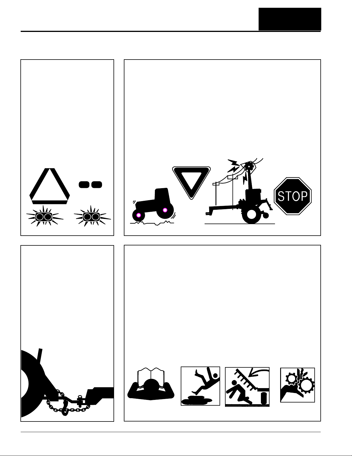
Table of Contents
Important Safety Information
These are common practices that may or may not be applicable to the products described in
this manual.
Use Safety
Lights and Devices
▲ Slow moving tractors, self-
propelled equipment, and towed
implements can create a hazard
whendriven on publicroads.They
are difficult to see, especially at
night.
▲ Flashing warning lights and turn
signals are recommended
whenever driving on public roads.
Transport
Machinery Safely
▲ Comply with state and local laws.
▲ Maximum transport speed for
implement is 20 mph. DO NOT
EXCEED.Never travel at a speed
which does not allow adequate
control of steering and stopping.
Some rough terrain require a
slower speed.
▲ Sudden braking can cause a
towed load to swerve and upset.
Reduce speed if towed load is not
equipped with brakes.
▲ Use the following maximum
speed - tow load weight ratios as
a guideline:
20 mph when weight is less
than or equal to the weight of
tractor.
10 mph when weight is more
than weight of tractor but less
than double the weight of
tractor.
▲ IMPORTANT: Do not tow a load
that is more than double the
weight of tractor.
Use A Safety Chain
▲ A safety chain will help control
drawn machinery should it
separate from the tractor
drawbar.
▲ Use a chain with the strength
rating equal to or greater than
the gross weight of the towed
machinery.
▲ Attach the chain to the tractor
drawbar support or other
specified anchor location. Allow
only enough slack in the chain
to permit turning.
▲ Do not use safety chain for
towing.
Practice Safe
Maintenance
▲ Understand procedure before
doing work. Use proper tools and
equipment, refer to Operator’s
Manual for additional information.
▲ Work in a clean dry area.
▲ Lower the implement to the
ground, put tractor in park, turn off
engine, and remove key before
performing maintenance.
▲ Allow implement to cool
completely.
▲ Do not grease or oil implement
while it is in operation.
▲ Inspect all parts. Make sure parts
are in good condition & installed
properly.
▲ Remove buildup of grease, oil, or
debris.
▲ Remove all tools and unused
parts from implement before
operation.
RCP2660, RCPM2660, RCP3060 and RCPM3060 Parallel Arm Rotary Cutter 316-111M
2
1/11/13
Page 5
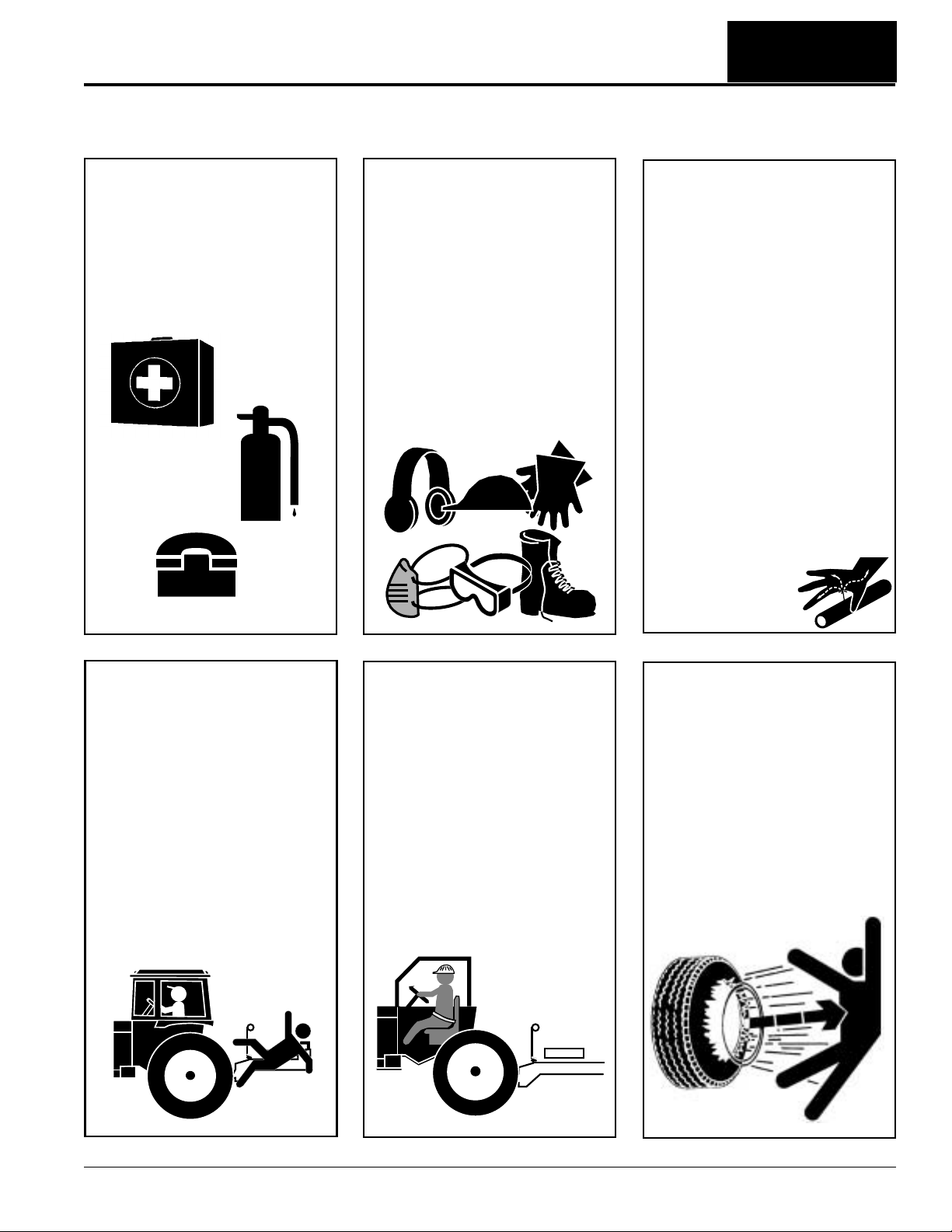
Table of Contents
Important Safety Information
These are common practices that may or may not be applicable to the products described in
this manual.
Prepare for Emergencies
▲ Be prepared if a fire starts.
▲ Keep a first aid kit and fire
extinguisher handy.
▲ Keep emergency numbers for
doctor, ambulance, hospital, and
fire department near phone.
911
Wear
Protective Equipment
▲ Wear protective clothing and
equipment appropriate for the job.
Avoid loose fitting clothing.
▲ Prolonged exposure to loud noise
can cause hearing impairment or
hearing loss. Wear suitable
hearing protection such as
earmuffs or earplugs.
▲ Operating equipment safely
requires the full attention of the
operator. Avoid wearing radio
headphones while operating
machinery.
Avoid High
Pressure Fluids Hazard
▲ Escaping fluidunder pressure can
penetrate the skin causing
serious injury.
▲ Avoid the hazard by relieving
pressure before disconnecting
hydrauliclines or performing work
on the system.
▲ Make sure all hydraulic fluid
connections are tight and all
hydraulic hoses and lines are in
good condition before applying
pressure to the system.
▲ Use a piece of paper or
cardboard, NOT BODY PARTS, to
check for suspected leaks.
▲ Wear protective gloves and safety
glasses or goggles when working
with hydraulic systems.
▲ If an accident occurs, see a
doctor immediately. Any fluid
injected into the skin must be
treated within a few hours or
gangrene may result.
Keep Riders
Off Machinery
▲ Riders obstruct the operator’s
view, they could be struck by
foreign objects or thrown from the
machine.
▲ Never allow children to operate
equipment.
Use Seat Belt and ROPS
▲ Operate only tractors equipped
with Roll-Over Protective
Structure (ROPS) and seat belt.
▲ Fasten seat belt snugly and
securely to help protect operator
from being thrown, crushed, or
severely injured if a rollover
occurs; and from falling off the
tractor and being ran over by the
tractorand/or cutter. Not using the
seat belt can result in serious
injury or death.
▲ Wearing protective equipment
such as safety shoes, safety
glasses, hard hat, and ear plugs
is highly recommended.
Tire Safety
▲ Tire changing can be dangerous
and should be preformed by
trained personnel using the
correct tools and equipment.
▲ When inflating tires, use a clip-on
chuck and extension hose long
enough to allow you to stand to
one side and NOT in front of or
over the tire assembly. Use a
safety cage if available.
▲ When removing and installing
wheels, use wheel handling
equipment adequate for the
weight involved.
1/11/13
RCP2660, RCPM2660, RCP3060 and RCPM3060 Parallel Arm Rotary Cutter 316-111M
3
Page 6
Important Safety Information
Table of Contents
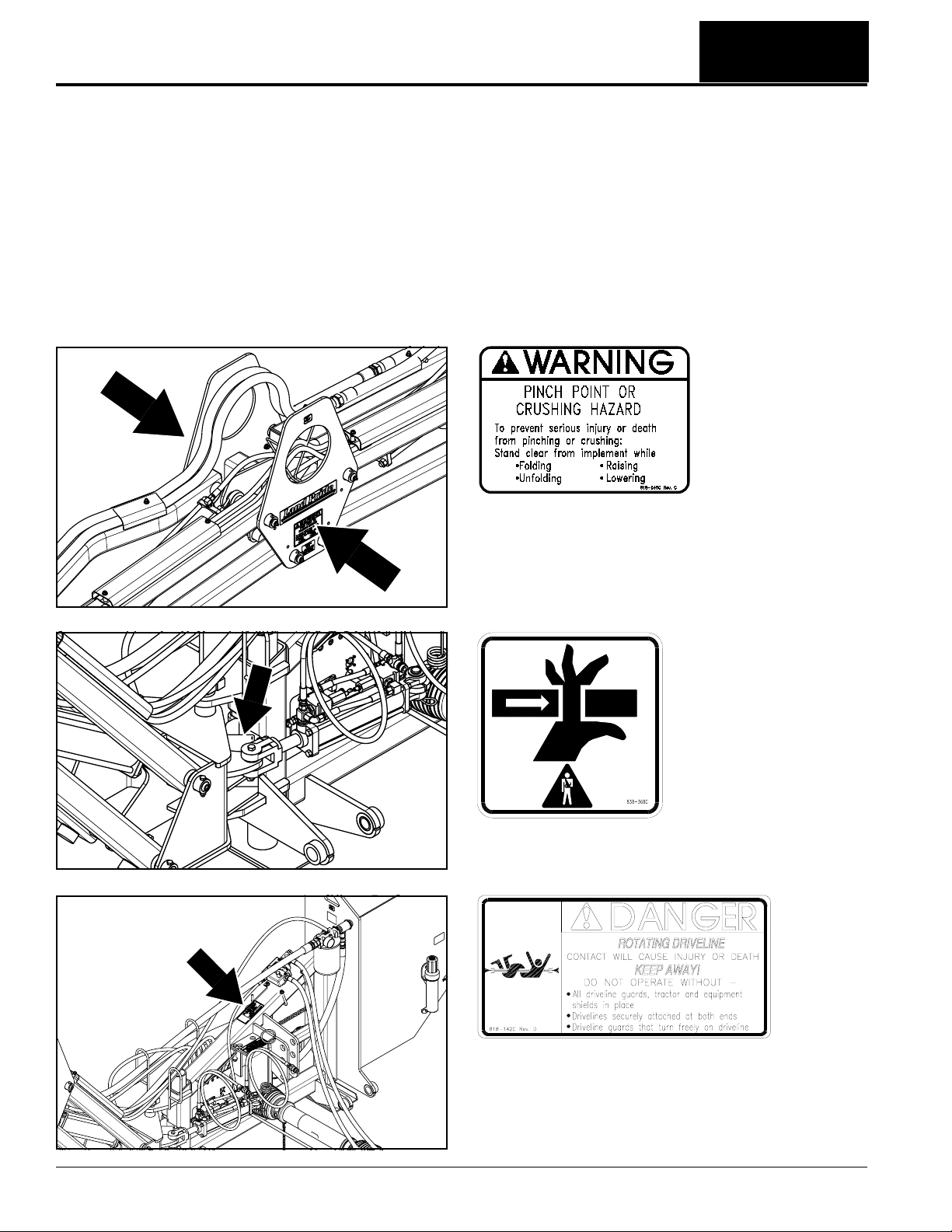
Safety Labels
YourParallelArm Rotary Cutter comes equippedwithall safety
labels in place. They were designed to help you safely operate
your implement. Read and follow their directions.
1. Keep all safety labels clean and legible.
2. Refer to this section for proper label placement. Replace
all damaged or missing labels. Order new labels from your
nearest Land Pride dealer. To find your nearest dealer,
visit our dealer locator at www.landpride.com.
3. Some new equipment installed during repair requires
safety labels to be affixed to the replaced component as
specified by Land Pride. When ordering new components
make sure the correct safety labels are included in the
request.
4. Refer to this section for proper label placement.
To install new labels:
a. Clean the area the label is to be placed.
b. Spray soapy water on the surface where the label is to
be placed.
c. Peel backing from label. Press firmly onto the surface.
d. Squeeze out air bubbles with the edge of a credit card
or with a similar type straight edge.
818-045C
Warning - Pinch Point Hazard
2-Places
22058
22057
838-368C
Warning - Pinch Point Hazard
818-142C
Danger - Rotating Driveline Hazard
26694
RCP2660, RCPM2660, RCP3060 and RCPM3060 Parallel Arm Rotary Cutter 316-111M
4
1/11/13
Page 7
Important Safety Information
30031
Table of Contents
818-229C
Amber Reflector
30032
22007
818-230C
Red Reflector
818-230C
Red Reflector (2 places)
1/11/13
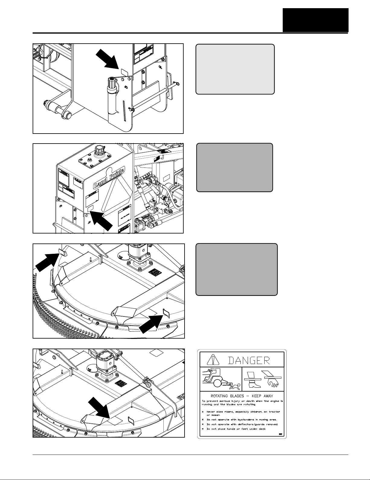
818-564C
Danger - Keep Away
22007
RCP2660, RCPM2660, RCP3060 and RCPM3060 Parallel Arm Rotary Cutter 316-111M
Rotating Blade Hazard
5
Page 8
Important Safety Information
Table of Contents
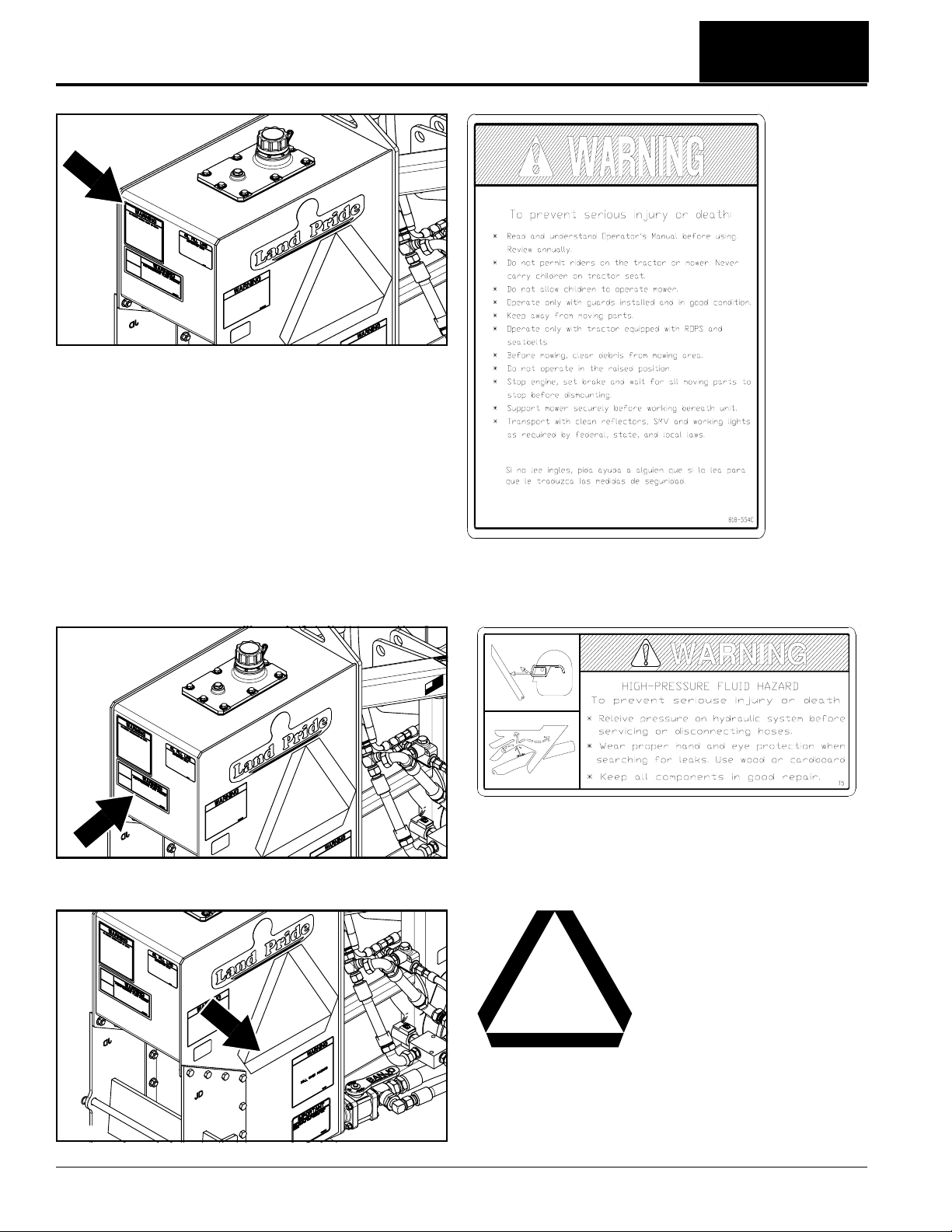
22006
22006
818-830C
Warning/Danger/Notice - Combination Safety Decal
818-556C
Danger - Thrown Object
Hazard (3-Places)
22006
RCP2660, RCPM2660, RCP3060 and RCPM3060 Parallel Arm Rotary Cutter 316-111M
6
818-555C
Danger - Rotating
Blades Keep Away
1/11/13
Page 9
Important Safety Information
22007
Table of Contents
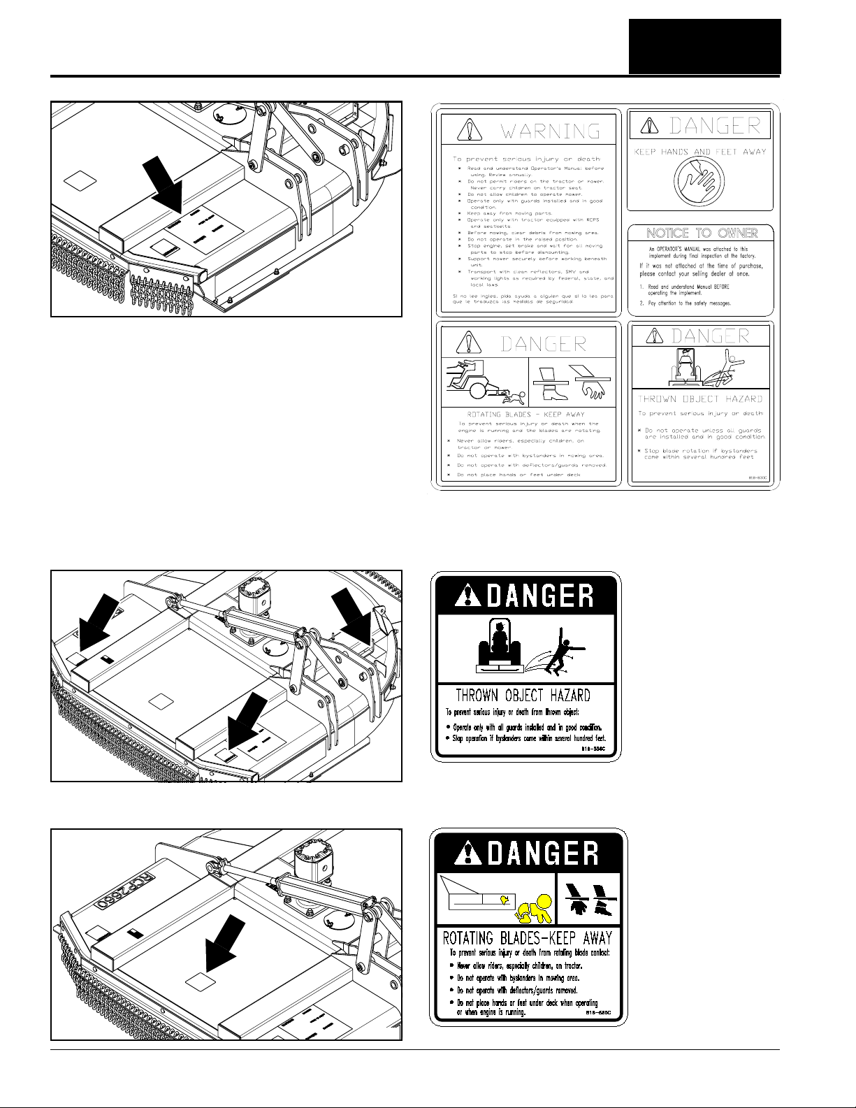
818-339C
Warning - High Pressure
Fluid Hazard
30032
30032
818-391C
Warning - Tractor Roll
Over Hazard
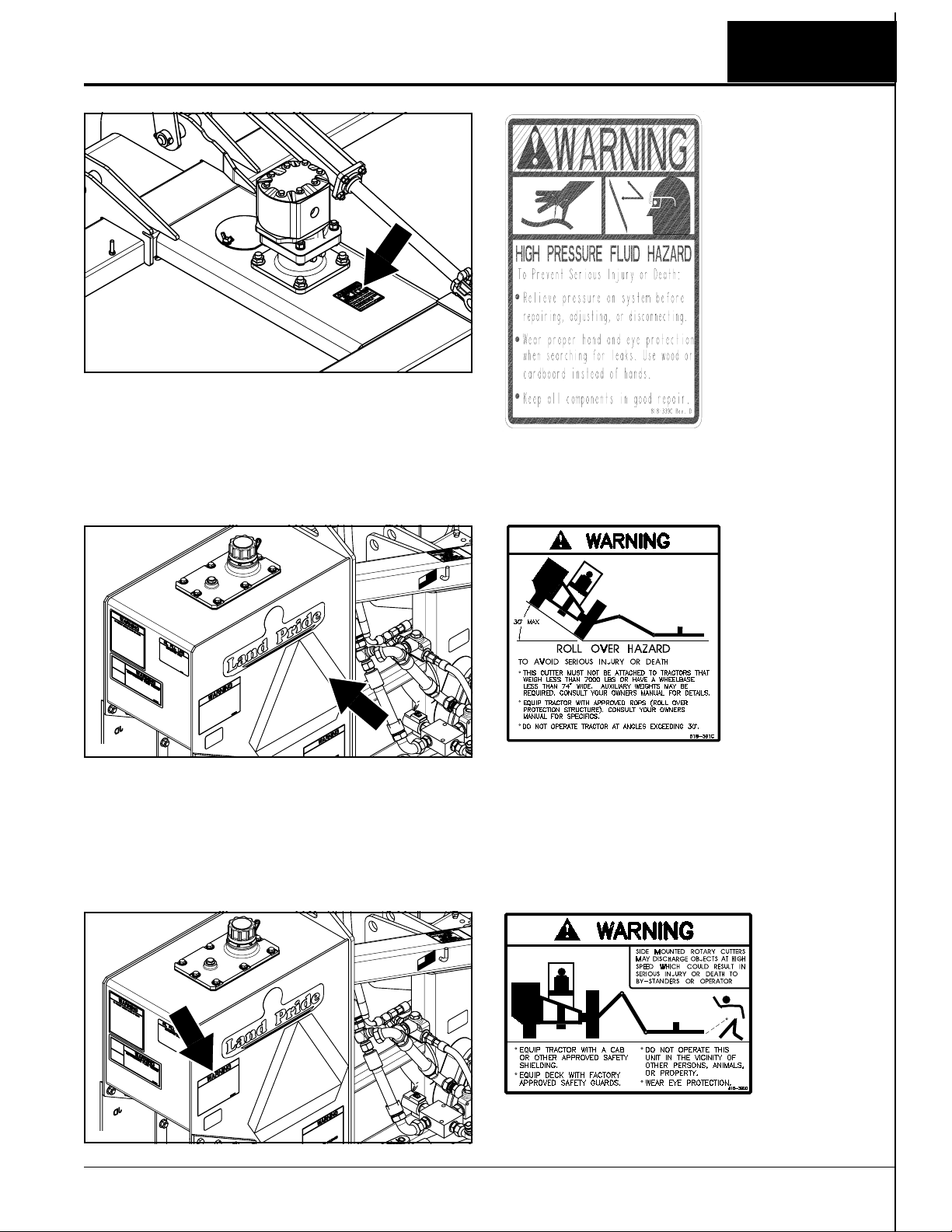
818-390C
Warning - Thrown
Object Hazard
1/11/13
RCP2660, RCPM2660, RCP3060 and RCPM3060 Parallel Arm Rotary Cutter 316-111M
7
Page 10
Important Safety Information
30032
Table of Contents
30032
818-554C
Caution - General Safety Information
818-831C
Warning - High Pressure Fluid Hazard
30032
RCP2660, RCPM2660, RCP3060 and RCPM3060 Parallel Arm Rotary Cutter 316-111M
8
818-003C
Slow Moving Vehicle Emblem
1/11/13
Page 11
Important Safety Information
Table of Contents
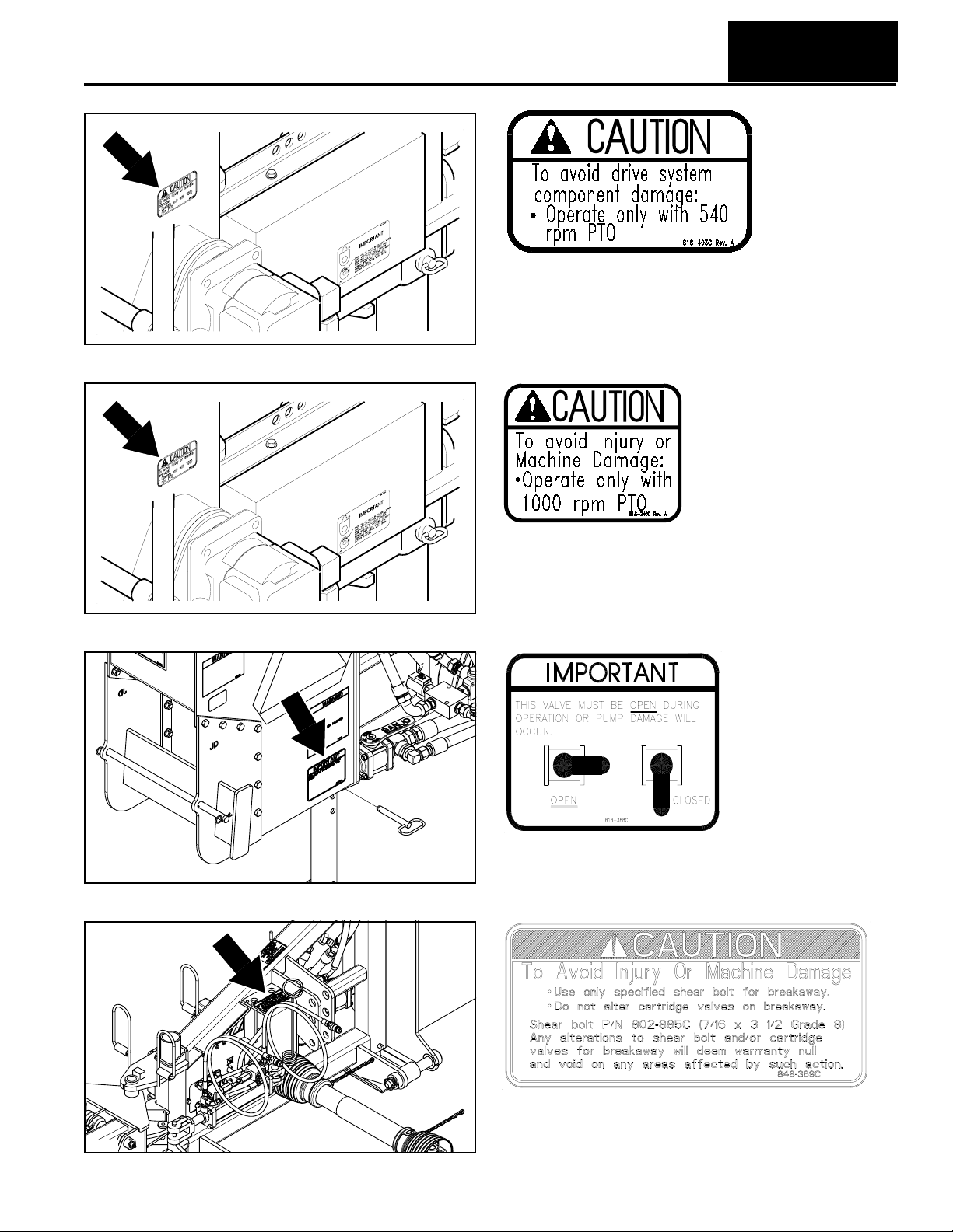
818-403C
(Used only on RCP2660 & RCP3060 Series)
Caution - Operate only with 540 rpm PTO
12324
30032
818-240C
(Used only on RCPM2660 & RCPM3060 Series)
Important - Operate only with 1000 rpm PTO
12324
818-388C
Important - Valve must be open
30033
1/11/13
848-369C
Caution: Avoid Injury or Machine Damage
RCP2660, RCPM2660, RCP3060 and RCPM3060 Parallel Arm Rotary Cutter 316-111M
9
Page 12
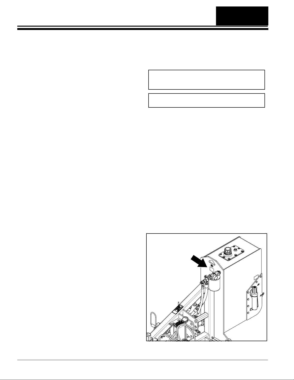
Table of Contents
Introduction
Introduction
Land Pride welcomes you to the growing family of new
product owners.
ThisRotaryCutter has been designed withcare and built
by skilled workers using quality materials. Proper
assembly,maintenance,andsafeoperatingpractices will
help youget years of satisfactory use from this machine.
Application
The Hydraulic Parallel Arm Rotary Cutters are designed
and built by Land Pride to provide excellent cutting
performance on ditch banks and other sloping areas
adjacent to right-of-ways, lakes, ponds, and streams.
They are designed to work equally as well in and around
areas of restricted access such as overor under fences,
guardrails, low overhanging branches, tree limbs, and
hedges. These units perform extremely well in tall grass
cutting applications and will easily cut through standing
brush up to two inches in diameter. An optional cutter
head equipped with two forward and one rear gauge
wheel is also available for customers who want to
maintain a constant cutting height with minimal control
lever manipulation.
The RCP2660 and RCPM2660 cutters are adapted for
Category 2 or 3 three-point hitch mounting on 75 hp. to
150 hp. tractors weighing 8,000 lbs. or more.
The RCP3060 and RCPM3060 cutters are adapted for
Category 2 or 3 three-point hitch mounting on 95 hp. to
175 hp. tractors weighing 12,000 lbs. or more.
The Hydraulic drive requires 540 rpm input PTO speed
for RCP2660 & RCP3060 models and 1000 rpm for
RCPM2660 & RCPM3060 models. Depending upon
hydraulicconfiguration,one,two,or four duplexhydraulic
outlets are required on the tractor to operate the cutter’s
parallel arms and deck angle.
See “Specifications & Capacities” on page 53
and “Features & Benefits” on page 55 for additional
information and performance enhancing options.
Terminology
“Right” or “Left” as used in this manual is determined by
facingthe direction the machine will operate while in use
unless otherwise stated.
Definitions
IMPORTANT: A special point of information related
to the following topic. Land Pride’s intention is this
information must be read & noted beforecontinuing.
NOTE: A special point of information that the
operator should be aware of before continuing.
Owner Assistance
The Online Warranty Registration or Warranty
Registration card should be completed by the dealer at
the time of purchase. This information is necessary to
provide you with quality customer service.
The parts on your ParallelAr m Rotary Cutter have been
specially designed by Land Pride and should only be
replaced with genuine Land Pride parts. Contact a Land
Pride dealer if customer service or repair parts are
required. Your Land Pr ide dealer has trained personnel,
repair parts, and equipment needed to service the
implement.
Serial Number
Model No. _____________Serial No. _______________
For quick reference and prompt service, record model
number and ser ial number in the spaces provided above
and again on warranty page 59. Always provide model
and serial number when ordering parts and in all
correspondences with your Land Pr ide dealer. Refer to
Figure 1 for location of your serial number plate.
Using This Manual
•
This Operator’s Manual is designed to help familiarize
you with safety, assembly, operation, adjustments,
troubleshooting, and maintenance. Read this manual
and follow the recommendations to help ensure safe
and efficient operation.
• The information contained within this manual was
current at the time of printing. Some parts may change
slightly to assure you of the best performance.
• To order a new Operator’s or Parts Manual contact
your authorized dealer. Manuals can also be
downloaded, free-of-charge from our website at
www.landpride.com.
RCP2660, RCPM2660, RCP3060 and RCPM3060 Parallel Arm Rotary Cutter 316-111M
10
30033
Serial Number Plate Location
Figure 1
1/11/13
Page 13

Table of Contents
Introduction
Further Assistance
Your dealer wants you to be satisfied with your new
cutter.If for anyreasonyou do notunderstand anypart of
thismanual or are not satisfied with the service received,
the following actions are suggested:
1. Discuss the matter with your dealership ser vice
manager making sure that person is aware of any
problemsyou mayhave and has had the opportunity
to assist you.
2. If you are still not satisfied, seek out the owner or
general manager of the dealership, explain the
problem, and request assistance.
3. For further assistance write to:
Land Pride Service Department
1525 East North Street
P.O. Box 5060
Salina, Ks. 67402-5060
E-mail address
lpservicedept@landpride.com
1/11/13
RCP2660, RCPM2660, RCP3060 and RCPM3060 Parallel Arm Rotary Cutter 316-111M
11
Page 14
Section 1: Assembly & Set-up
Table of Contents
Section 1: Assembly & Set-up
Tractor Requirements
Horsepower
Tractor horsepower must be capable of controlling the
Parallel Arm Rotary Cutter under all operating
conditions. Smaller tractors must not be used.
RCP2660 & RCPM2660
Horsepower Range . . . . . . . . . . . . . . . . . .75-150 HP
RCP3060 & RCPM3060
Horsepower Range . . . . . . . . . . . . . . . . . .95-175 HP
Weight
Absolute Minimum: Tractor weightmust be sufficient to
controlthe ParallelArmRotaryCutter underall operating
conditions. Tractors not meeting the absolute minimum
weight listed below must not be used.
Basic Minimum: A right-hand overturning torque load is
present on the tractor when parallel ar ms are fully
extended. Tractors will need auxiliary counterbalance
weights added if the tractor’s total weight is less than the
basic minimum weight listed below.
It is best to add auxiliary weights to the left rear tractor
wheel. In addition, up to eight 100 lb. suitcase type
weights can be added to the optional weight hanger on
the hydraulic reser voir. However, adding weights to the
reservoir can lighten the tractor’s front end.
RCP2660 & RCPM2660
Tractor absolute minimum weight. . . . . . . . 8,000 lbs.
Tractor basic minimum weight. . . . . . . . . . 8,500 lbs.
RCP3060 & RCPM3060
Tractor absolute minimum weight. . . . . . . 12,000 lbs.
Tractor basic minimum weight. . . . . . . . . 13,500 lbs.
The front gauge wheel and mount may interfere with the
right rear tractor tire when deck is folded for transporting.
This is especially true if the outside face of the tire is
more than 47" away from the tractor center. Tractors
equipped with dual wheels may need the outside right
rear wheel removed. The RCP(M)3060 cutter requires a
dual wheel on the left-hand side or wheel weights equal
to the weight of a dual wheel.
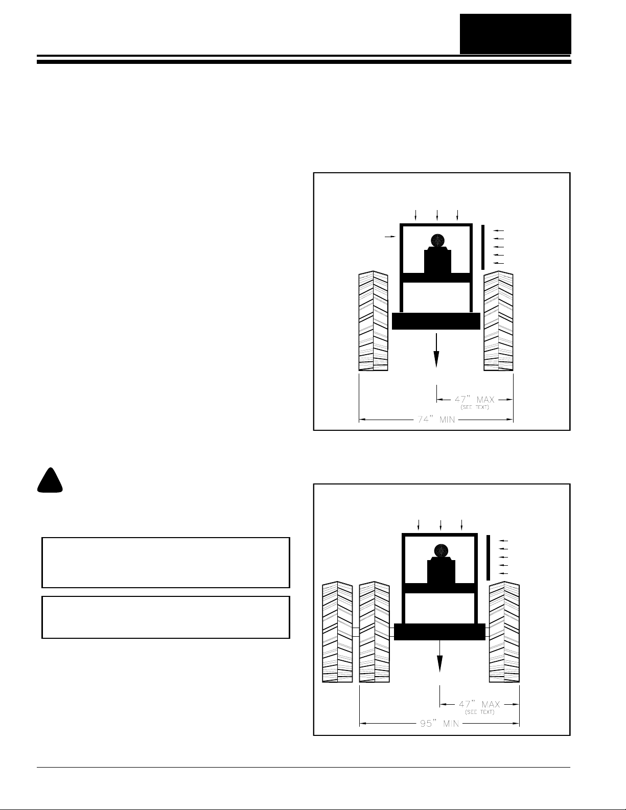
TRACTOR CAB OR
ROLL OVER
PROTECTIVE STRUCTURE
OPERATOR
PROTECTIVE
SHIELD
8,000 LBS. MIM.
12250
RCP2660 & RCPM2660 Minimum Tractor Requirements
Figure 1-1
!
Front tractor weights and/or ballast to tires may be required
to offset weight of cutter and auxiliary weights. Consult your
tractor manual to determine if additional ballast is needed.
WARNING
IMPORTANT: Extended parallel arms will pull the
tractor’s front to the right. When necessary, add
weight to the tractor front to stabilize it. Consult your
tractor’s manual for allowable added weights.
IMPORTANT: The tractor’s right rear wheel should
be pressurized to the manufactures highest
recommended air pressure.
LEFT-HAND DUAL
OR LEFT-HAND
WHEEL WEIGHTS
Wheel Base
Refer to Figure 1-1 & Figure 1-2:
Rear wheel base must meet minimum requirements
when measured from outside face to outside faceof rear
tractor tires. Smaller wheel bases must not be used.
RCP2660 & RCPM2660
Rear Wheel Base. . . . . . . . . . . . . . . . . .74" minimum
RCP3060 & RCPM3060
Rear Wheel Base . . . . . . . . . . . . . . . . . 95" minimum
RCP2660, RCPM2660, RCP3060 and RCPM3060 Parallel Arm Rotary Cutter 316-111M
12
RCP3060 & RCPM3060 Minimum Tractor Requirements
TRACTOR CAB OR
ROLL OVER
PROTECTIVE STRUCTURE
REQUIRED
OPERATOR
PROTECTIVE
SHIELD
12,000 LBS. MIM.
24583
Figure 1-2
1/11/13
Page 15

Section 1: Assembly & Set-up
Table of Contents
Hitch
A 3-Point Category II or Category III hitch is required.
The lower 3-Point arms of the 3-Point hitch must be
stabilized to prevent side-to-side movement. Most
tractors have sway blocks or adjustable chains for this
purpose.
Hydraulic Outlets
Thenumber of tractorhydraulicduplexoutlets required is
dependent upon how the Rotary Cutter is set-up.
Independent Control:
One duplex outlet is required to operate the breakaway
cylinder.APTO drivenpump onthe unit pumpshydraulic
fluid from the reservoir to the parallel arm cylinders and
deck pivot cylinder. The cylinders are solenoid activated
withmomentary push button switches at the control stick.
Solenoid Control:
Two duplex outlets are required. One duplex outlet is
required to operate the breakaway cylinder. The second
duplex outlet operates the parallel arm cylinders and
deck pivot cylinder.The cylinders aresolenoid activated
withmomentary pushbuttonswitchesat thecontrolstick.
The second duplex outlet must be capable of continuous
hydraulic fluid flow.
Tractor Control:
Four duplex outlets are required to operate the parallel
arm cylinders, deck pivot cylinder, and breakaway
cylinder. Each cylinder is connected to a duplex outlet
and activated with tractor control levers. Each duplex
outlet must be capable of infinite variable flow control
(turtle/rabbit control) with center detent “OFF” levers.If
gauge wheels are included, “ARM 2” and “Deck Pivot”
levers must be capable of being placed in float position .
PTO Speed
TheRCP cutters requires540 rpmPowerTake-Off (PTO)
speed and the RCPM cutter requires 1000 rpm PTO
speed to operate the hydraulic pump(s) & motor.
Required tractor horsepower to operate thepump(s) and
motor is approximately 30 HP.
Protective Equipment Requirements
Refer to Figure 1-1:
The tractor MUST be equipped with protective
equipment designed to shield the operator from thrown
objects and tractor rollover. An enclosed tractor cab with
a Roll Over Protective Structure (ROPS) may qualify.
See the tractor’smanual to see if it qualifies.
Tractors with only a ROPS must havea protective shield
added to the right-hand fender. A universal operator
protective shield is available from Land Pr ide. Refer to
page 36 for additional information and installation.
It is also recommended that a protective shield or screen
be added to the right-hand side of the tractor engine
cowling and radiator. This will help protect the tractor’s
finish and radiator against thrown objects.
Dealer Preparations
This cutter has been assembled at the factory. However,
some preparations will be necessary to attach the cutter
to customer’s tractor.
• Make certain the intended tractor conforms to the
“Tractor Requirements” on page 12.
• Review and check off Preparation Checklist below
before proceeding.
Preparation Checklist
Upper hitch pin is not Included with unit. Determine
customer’s tractor hitch type. (Cat II or Cat III). Buy
required upper hitch pin locally or order a Land Pride
hitch pin if customer’s tractor does not included the pin.
See Land Pride’s upper hitch pin part numbers below.
805-079C - Upper Hitch Pin Cat II (1" dia. x 3 3/8" usable)
805-196C - Upper Hitch Pin Cat III (1 1/4" dia. x 3 3/8" usable)
Before operating this unit, 80-90 EP Gear Lube must
be added to the gearbox & motor as indicated in the
“Maintenance & Lubrication” section for “Speed
Increaser” on page 52 of this manual.
35 Gallons of Hydraulic Fluid is needed for the
hydraulic reser voir. Use any high quality mineral based
hydraulic fluid such as Mobilfluid 424 with a viscosity
rating of 10W-30.
Additional hydraulic fluid (approx 2 gallons) for the
tractor reservoir.
Miscellaneous assembly tools: hammer, tape measure,
assortment of wrenches and sockets, and spirit level.
Quick disconnect adaptors that match tractor’s duplex
outlets. Quantity required depends on option selected:
(4) If equipped with solenoid control box.
(8) If not equipped with hose hook-up.
Possibleneed for forklift or hoist capable of lifting 2500
lbs.
Auxiliary tractor weights (depending on tractor size).
See “Tractor Requirements” on page 12
A minimum of two people available during assembly.
If a pin, bolt or other part has been removed, and you
are unsure where it is used, use the Parts Manual to
identify it. Be sure the part gets used in the correct
location. By double checking while you assemble, you
will lessen the chance of using a bolt incorrectly that
may be needed later.
Safety decals are legible and undamaged from
shipment.
PTO driveline and loose parts bag/box shipped with
the cutter are present.
.
1/11/13
RCP2660, RCPM2660, RCP3060 and RCPM3060 Parallel Arm Rotary Cutter 316-111M
13
Page 16
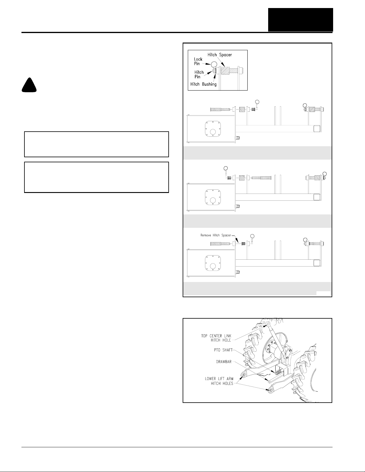
Table of Contents
Section 1: Assembly & Set-up
The following set-up instructions are standard for all
options. They should be completed before continuing
with optional set-up instructions.
Hooking-up the Rotary Cutter
!
A Crushing Hazard exists when hooking-up equipment to a
tractor. Do not allow anyone to stand between tractor and
implement while backing-up to implement. Do not operate
hydraulic 3-Point lift controls while someone is directly
behind tractor or near implement.
DANGER
IMPORTANT: Hydraulic fluid must be added to the
cutterhydraulicreservoir before operating thepump.
Otherwise, the hydraulic pump will be damaged.
NOTE: Driveline installation instructions will follow
after hooking-up cutter to a tractor. This is because
the distance between tractor PTO shaft and speed
increaser input shaft can vary from tractor to tractor.
Category III 3-Point Hitch
Prepare cutter as follows:
1. Be sure transport safety chain is hooked to the deck.
See Figure 1-9 on page 17.
2. Position cutter on a flat level concrete surface.
Refer to Figure 1-3:
3. There are three hitch categories represented in
Figure 1-3. Determine which category fits the tractor
being used and arrange cutter hitch pins as shown
for that category.
Refer to Figure 1-4:
4. Slowly back tractor up to the Rotary Cutter while
using tractor’s 3-Point hydraulic controls to align
lower hitch link holes with clevis holes on the cutter.
5. Place tractor gear selector in par k and/or set brakes,
shut engine off, and remove ignition key.
6. Aligned and positioned tractor’s lower hitch holes in
the clevises. Attach the lower arms to the clevises
with hitch pins and secure with linch pins.
7. Adjusttop centerlink in orout toalign centerlink hole
with the cutter’s center hitch pin hole. Connect top
center link to cutter hitch pin hole using customer
supplied clevis pin and linch pin.
8. Makecer tain the lower3-Point arms are stabilized to
prevent excessive side movement.
9. Returnto tractorandslowlyraise tractor 3-Pointhitch
about 1 to 2 inches. Stow jack stands in the raised
position.
10. Slowly operatetractor's 3-Pointarms upand downto
check clearance between cutter components and
tractorcomponents. Moveorremovetractor drawbar
if it interferes with cutter.
11. Adjust tractor's lower arms to level cutter frame from
left to right.
Category II Quick HItch
Category II 3-Point Hitch
24642
Hitch Pin Configuration (Based on Hitch Category)
Figure 1-3
23998
Tractor 3-Point Hitch
Figure 1-4
12. Adjust center top-link to level cutter frame from front
to rear.
13. Final deck leveling adjustments will be made later.
RCP2660, RCPM2660, RCP3060 and RCPM3060 Parallel Arm Rotary Cutter 316-111M
14
1/11/13
Page 17
Section 1: Assembly & Set-up
Table of Contents
Driveline Installation
!
Do not engage tractor PTO while hooking-up and unhooking
driveline or while someone is standing near the driveline. A
person’s body and/or clothing can become entangled in the
driveline resulting in serious injury or death.
All guards and shields must be installed and in good working
condition at all times during cutter operation.
Always disengage PTO, engage parking brake, shut tractor
engine off, remove switch key, and wait for blades to come to
a complete stop before dismounting tractor.
Do not over-speed PTO or machine breakage may result.
Some tractors are equipped with multispeed PTO ranges. Be
certain your tractor’s PTO is set for the cutter’s rated PTO
speed. See Specifications & Capacities for rated PTO speed.
DANGER
!
DANGER
!
WARNING
!
WARNING
IMPORTANT: Do not engage tractor PTO until
driveline is fully connected and hydraulic fluid has
been added to the cutter reservoir.
IMPORTANT: A quick hitch may be used, but is not
recommended because it moves the cutter deck
back about 5" and impedes operator visibility.
IMPORTANT: An additional driveline may be
required if cutter is to be used on more than one
tractor, especially if a Quick Hitch is used.
The dr iveline must belubricated before puttingit into
service. Refer to “Lubrication Points” on page 50.
The tractor’s PTO shaft and cutter gearbox shaft
must be aligned and level with each other when
hooking-up the driveline to the tractor.
6. If driveline yokewill not lock in place, skip to “Check
Driveline Collapsible Length” below.
IMPORTANT: Two small chains are supplied with
the driveline.To keepdriveline shields from rotating,
thesechains mustbe attachedto theouter andinner
driveline shields and to the cutter and tractor.
7. Attach safety chain on the inner driveline shield to
the parallel arm frame. Re-latch safety chain to the
inner driveline shield.
8. Attach safety chain on the outer driveline shield to
the tractor frame. Re-latch safety chain to the outer
driveline shield.
9. Continue with “Check Driveline Collapsible
Length” below.
Check Driveline Collapsible Length
IMPORTANT: A driveline that is too long can bottom
out causing structural damage to tractor and cutter.
Alwayscheckdrivelinecollapsedlength duringinitial
setup, when connecting to a different tractor, and
when alternating between using a quick hitch and a
standard 3-Pointhitch. More than one driveline may
be required to fit all applications.
1. Make sure dr iveline is properly installed and level
beforecheckingdrivelinecollapsiblelength.(Referto
“Driveline Installation” instructions on page 15.)
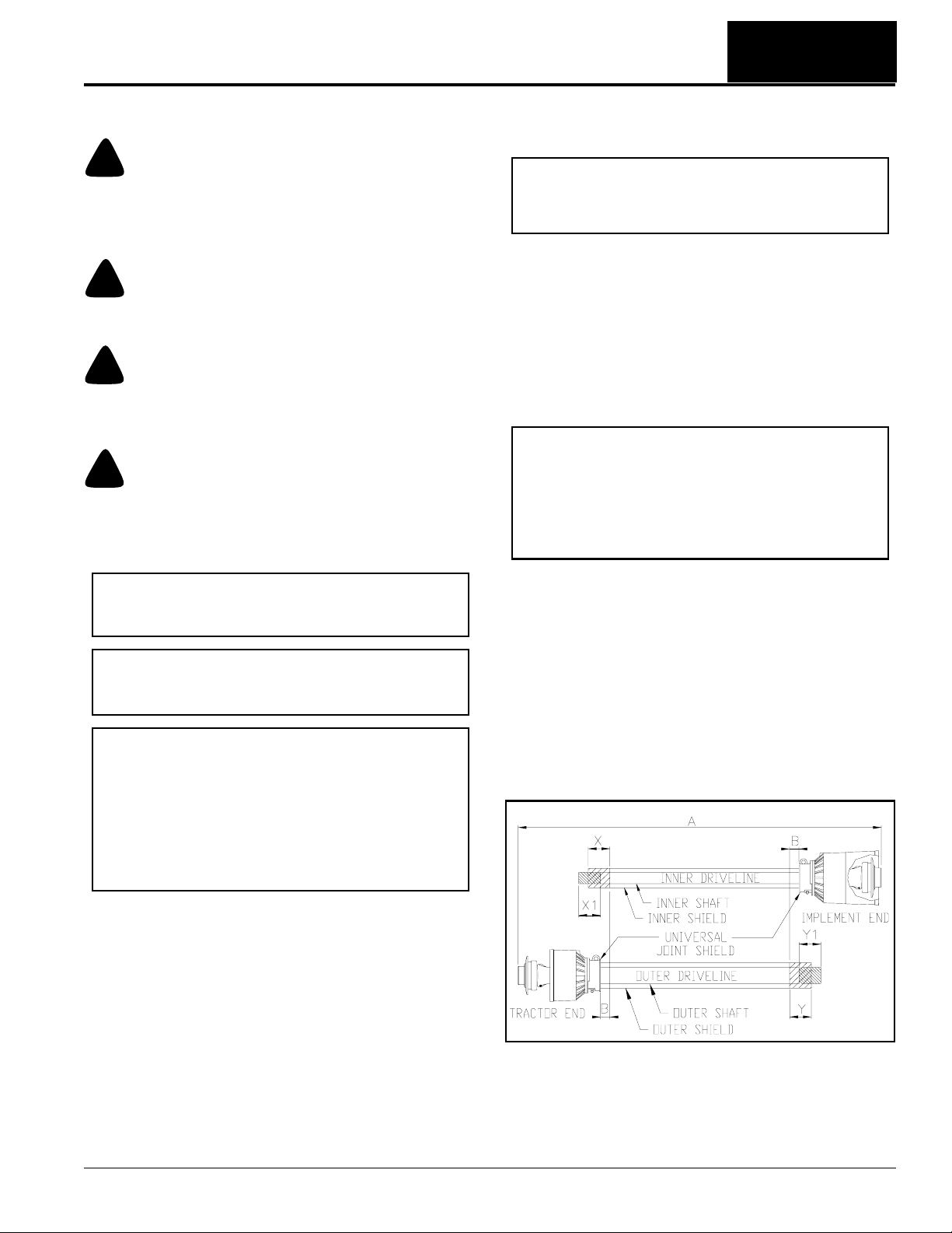
Refer to Figure 1-5:
2. With driveline level, measure (“B” dimension) back
from universal joint shield to end of outer driveline
shield as shown in Figure 1-5.
3. If measurement is 1" or more, skip to “Check
Driveline Maximum Length” on page 16. If
measurement is less than 1",shorten drivelineusing
instructions provided under “Shorten Driveline” on
page 16.
Refer to Figure 1-5:
1. Start tractor and slowly engage 3-Point controls to
move lower arms until the PTO shaft for the speed
increaser is aligned and levelwith tractor PTO shaft.
Securely block cutter in this position.
2. Place tractor gear selector in park, shut tractor
engine off, set park brake, and remove switch key.
3. Slide inner yoke of driveline over speed increaser
shaft and secure with locking collar.
4. Slide outer yoke of driveline over tractor PTO shaft
and secure with locking collar.
5. Push and pull on driveline yokes to be certain they
are securely fastened to the speed increaser and
PTO shafts.
1/11/13
RCP2660, RCPM2660, RCP3060 and RCPM3060 Parallel Arm Rotary Cutter 316-111M
22009
Shortening PTO Driveline Shields & Shafts
Figure 1-5
15
Page 18
Section 1: Assembly & Set-up
Table of Contents
Shorten Driveline
Refer to Figure 1-5:
Be sure to check driveline collapsed length first. If
required, shorten driveline as follows:
1. Un-hook driveline and safety chain from tractor PTO
shaft. Pull outer and inner drivelines apart.
2. Reattach outer dr iveline to tractor PTOshaft. Pull on
inner and outer driveline yokes to be sure universal
joints are properly secured.
3. Holdinner and outerdrivelines parallel to each other:
a. Measure 1" (“B” dimension) back from outer
drivelineuniversal jointshield and makea markat
this location on the inner driveline shield.
b. Measure 1" (“B” dimension) back from the inner
drivelineuniversaljoint shieldand makea mar k at
this location on the outer driveline shield.
4. Remove driveline from tractor PTO shaft and speed
increaser shaft.
5. Measure from end of inner shield to scribed mark
(“X” dimension). Cutoff innershield atthe mark. Cut
same amount off the inner shaft (“X1” dimension).
6. Measure from end of outer shield to scribed mark
(“Y” dimension). Cutoff outershield at themark. Cut
same amount off the outer shaft (“Y1” dimension).
7. Remove all burrs and cuttings.
8. Continuewith“Check Driveline Maximum Length”.
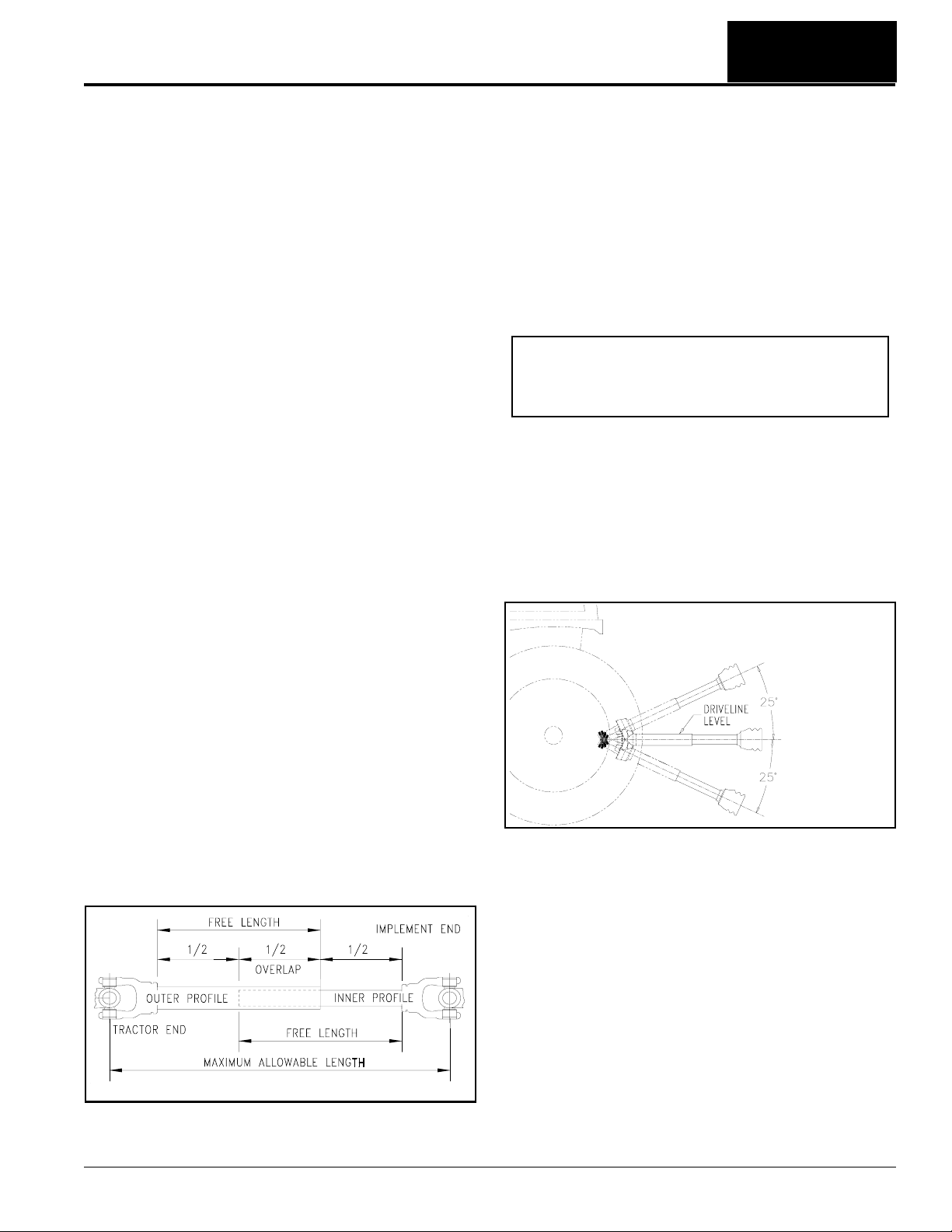
Check Driveline Maximum Length
Refer to Figure 1-6:
Thedrivelinemaximum allowablelength must,when fully
extended,haveaminimum overlap ofprofile tubesbynot
less than 1/2 the free length with both inner and outer
profile tubes being of equal length.
1. Apply multi-purpose greaseto the inside of the outer
shaft and reassemble the driveline.
2. Assemblethe twodriveline profiles together with just
1/2 overlapping of the profile tubes as shown. Once
assembled,measureandrecordmaximum allowable
length here. ________
3. Continue with “Check Driveline Interference”.
Check Driveline Interference
1. Make certain driveline yokes and safety chains are
properly attached. See steps 7 -9 on page 15.
2. Start tractorandraise ParallelArmRotar y Cutterjust
enough to remove support blocks from under the
cutter.
3. Slowly engage tractor hydraulic3-Point control lever
to lower cutter while checking for sufficient drawbar
clearance. Movedrawbar ahead, aside, or remove if
required.
Refer to Figure 1-7:
IMPORTANT: Avoid premature driveline
breakdown. A driveline that is operating must not
exceed an angle of 25 degrees up or down while
operating 3-Point lift.
4. With PTO off, raise implement fully up to make the
following checks below. If driveline exceeds any of
the limits listed, set tractor 3-Point lift limiter at a
height that will keep the driveline within its lift limits
and to avoid premature driveline breakdown.
• Driveline does not exceed 25
o
up.
• Driveline does not exceed maximum allowable
length recorded in step 2 under “Check Driveline
Maximum Length”.
24872
Maximum PTO Driveline Movement During Operation
Figure 1-7
24804
Outer Shielding has been removed for clarity.
Driveline Maximum Extended Length
Figure 1-6
1/11/13
RCP2660, RCPM2660, RCP3060 and RCPM3060 Parallel Arm Rotary Cutter 316-111M
16
Page 19

Section 1: Assembly & Set-up
Table of Contents
Hydraulic Reservoir Oil Fill
Refer to Figure 1-8:
The Rotar y Cutter is shipped without hydraulic fluid.
1. Parkcutter on a levelsurface,set park brake,turn off
ignition switch, and remove switch key.
2. Remove fill cap and dipstick from reservoir and add
35gallonsof Mobilfluic424to thehydraulicreservoir.
Use care to ensure that dust or other foreign
particles do not contaminate the fluid.
IMPORTANT: Any high quality mineral based
hydraulicfluidsuch as Mobilfluid 424 with a viscosity
rating of 10W-30 is acceptable. For alter nate fluids,
search on the web for "Mobilfluid 424" or go to
www.mobil.com.
3. Wipe dipstick clean. Fully insert it and remove.
Checkoil levelon dipstick.Fill with recommended oil
to the full mark. Replace fill cap and dipstick.
Transport Safety Chain
Refer to Figure 1-8 & Figure 1-9:
!
WARNING
Transport safety chain must remain hooked to the deck until
ready to extend parallel arms and deck cylinder. Float Switch
must be “OFF” until gauge wheels are resting on the ground.
The transpor t safety chain should always be hooked to
the deck hook when cutter is folded up. Otherwise, the
operating levers and/or push button switches could be
bumped or hoses could burst allowing deck to fall and
cause damage to cutter, tractor, and anyone nearby.
When unhooking the transport safety chain, make sure
the arm anddeck cylinders areretracted and if available,
theFloat Switch is set to “OFF”. Donot forcesafetychain
off the deck hook. If safetychain does not remove easily,
investigate the problem and correct before continuing.
Once unhooked, store safety chain on the storage hook.
Fill Cap With Dip Stick
Storage Hook
Transport Safety Chain
Drain Plug
Transport Safety Chain Shown in Storage Position
Figure 1-8
Deck Hook
Transport Safety Chain
Transport Safety Chain Shown Hooked for Transport
Figure 1-9
12443
22031
Breakaway Cylinder
Refer to Figure 1-10 on page 17:
The breakaway cylinder protects the Rotary Cutter from
damagewhen cutterdeckor parallelarm contactsa solid
objectwhile moving forward.Itdoes not protectthe cutter
while backing up. Always make certain the area behind
the cutter is clear before backing up. See Breakaway
Cylinder on page 37 for additional information.
IMPORTANT: A 1/2" bolt is installed for shipping
purposes only. This bolt must be remove before
connecting hydraulic hoses to the tractor.
1. Remove 1/2" shipping bolt from cutter before
connecting hydraulic hoses. DO NOT reinstall
shipping bolt.
2. Attach breakawayhoses to a single duplexoutlet on
the tractor as shown in Figure 1-10.
1/11/13
RCP2660, RCPM2660, RCP3060 and RCPM3060 Parallel Arm Rotary Cutter 316-111M
Important:
LocateandRemove
1/2" Shipping Bolt
Before Connecting
Hydraulic Hoses.
12256
Breakaway Cylinder Hose Connections
Figure 1-10
17
Page 20

Section 1: Assembly & Set-up
Table of Contents
Weight Hanger Assembly
Refer to Figure 1-11:
There are five different weight hangers that can be
attached to the reservoir. One of the five must be
installed for operation. See “Bolt-on Weight Hangers”
on page 35 for detailed description of availableweight
hangers.
NOTE: Case/International Harvest weight hanger
includes an L-shaped spacer. Be sure to locate this
spacer between the weight hanger side plate and
hydraulic reservoir tank in assembly.
1. Attach weight hanger (#1) to reservoir with four teen
1/2"-13 x 1 1/4" GR5 cap screws (#3) and hex flange
locknuts (#3).Tighten locknuts to the correct torque.
2. Attach manual storage container (#9) to the front
side of the reservoir with two 1/4"-20 x 1 1/4" GR5
cap screws (#4), flat washers (#7), and hex nylock
nuts (#6). Tighten nylock nuts to the correct torque.
3. Insert weight retainer pin (#2) through holes in
weight hanger and secure with hairpin cotters (#8).
Case/International Harvest Weight Hanger Only:
Locate L-shaped spacer between weight hanger
side plate and hydraulic reservoir.
NOTE: Installation of gauge wheel and ratchet jack
iseasier after the deck hasbeen lowered. Therefore,
it is best to install them just before making “Float
Positioning Control Check” on page 20 for Tractor
Controlor just before making “Float Switch ON/OFF
Push Button Check” on page 27 for Solenoid and
Independent Control.
Ratchet Jack Installation
1. Check 5/8" hex flange lock nuts securing bolts (#3).
They should be drawn up snug, not tight.
A-frame (#2) should pivot freely on the two bolts.
2. Cutties securing A-frame(#2) and rotate frame back
to position it behind the deck as shown.
3. Attach ratchet jack (#8) to the cutter deckwith 1" dia.
clevis pins (#6). Secure clevis pins with hair pin
cotters (#3).
4. Insert long handle in the rear ratchet jack and short
handle in the front ratchet jack. Secure handles with
cotter pins. Bend cotter pin legs to keep pins from
falling out.
NOTE: After deck cutting height is set, it is
recommended that the ratchet jack handles be
removed and stored with the tractor and cutter to
protect the deck finish.
30029
Weight Hanger Installation
Figure 1-11
Gauge Wheels (Optional)
Refer to Figure 1-12:
The deck with gauge wheels is shipped from the factory
completely assembled to the parallel arm with the
exception of installing the rear ratchet jack and one
gauge wheel.
Gauge Wheel Installation
1. Install 1 1/4" I.D. machine washer (#4) over yoke
spindle (#1) as shown.
2. Insert yoke spindle (#1) into the front support frame.
3. Install second 1 1/4" I.D. machine washer (#4) over
yoke spindle (#1).
4. Secure yoke spindle to frame with 5/16" dia. roll
pin (#7).
24617
Gauge Wheel Installation
Figure 1-12
RCP2660, RCPM2660, RCP3060 and RCPM3060 Parallel Arm Rotary Cutter 316-111M
18
1/11/13
Page 21

Table of Contents
Section 2: Hydraulic Set-up Options
Section 2: Hydraulic Set-up Options
Options
There are three basic Hydraulic Options for the Parallel
Arm RotaryCutter (TractorControl, SolenoidControl and
Independent Control). Each of the three basic options
can be purchased with or without gauge wheels. A brief
description of each follows:
Tractor Control
Refer to Figure 2-2:
Four duplex outlets are required to operate “ARM 1”,
“ARM 2”, “Deck Pivot”, and Breakaway cylinders. The
duplex outlets must be capable of infinite variable flow
control (turtle/rabbit control) and should have center
detent “OFF” control levers for controlling the position of
theparallelar m anddeckpivotcylinders. If gaugewheels
are included, “ARM 2” and “Deck Pivot” control levers
must be capable of being placed in float position.
The hydraulic motor on the deck is powered by a
hydraulicpump connected to the tractor’sPTO shaft and
is turned “ON” and “OFF” at the tractor’s PTO shaft.
Solenoid Control
Refer to Figure 2-14 on page 26:
With this arrangement, the breakaway cylinder is
coupled directly to a duplex outlet at the tractor and
operated with the tractor’s hydraulic control lever.
The remaining three cylinders (“ARM 1”, “ARM 2” &
“Deck Pivot”) are powered by one duplex outlet at the
tractor with the control lever set for continuos hydraulic
flow. A flow control valve mounted on the cutter frame
regulates oil flow through the solenoid valve block. The
three cylinders aresolenoid activated from the tractor
seat with momentary push buttons on the control stick.
If gauge wheels are mounted on the deck, the solenoid
valve block must also include two float valves(poppet
valves) so that “ARM 2” and “Deck Pivot” cylinders can
float with the deck as it is carried by the gauge wheels.
The hydraulic motor on the deck is powered by a
hydraulic motor pump connected to the tractor’s PTO
shaft and is turned “ON” and “OFF” at the tractor’s PTO
shaft.
If gauge wheels are mounted on the deck, the solenoid
valve block must also include two float valves(poppet
valves) so that “ARM 2” and “Deck Pivot” cylinders can
float with the deck as it is carried by the gauge wheels.
Tractor Control
NOTE: The response time with solenoid and
independent controlled cylinders is faster than
tractor controlled cylinders. Therefore, the operator
might want to consider going with solenoid
controlled cylinders or independent controlled
cylinders when frequent changes to deck
positioning are required.
Hydraulic Hose Hook-up
Refer to Figure 2-1:
Three cylinders are connect to three duplex outlets on
the tractor. Make sure these duplex outlets have infinite
variable flow control. Do Not run tractor to make
adjustments to hose hook-up. Adjustments will be made
laterduring Console Control LeverFunctional Checks on
page 20.
1. Connect “ARM 1” hoses to a single duplex outlet on
the tractor. This is best if connected to the control
closest to the operator.
2. Connect “ARM 2” hoses to the control lever next to
“ARM 1” lever.This control levermust be capable of
beingplaced infloat position whengauge wheelsare
included.
3. Connect “Deck Pivot” hoses to the control lever next
to “ARM 2” lever. This control lever must be capable
of being placed in float position when gauge wheels
are included.
Independent Control
Refer to Figure 2-14 on page 26:
With this arrangement, the breakaway cylinder is
coupled directly to a duplex outlet at the tractor and
operated with the tractor’s hydraulic control lever.
The remaining three cylinders (“ARM 1”, “ARM 2”, and
“Deck Pivot”) are powered by a cylinder pump mounted
on the back of the motor pump. The cylinders are
solenoid activated with momentary push buttons on the
control stick.
The hydraulic motor on the deck is powered by a
hydraulic motor pump connected to the tractor’s PTO
shaft. Because the PTO shaft must run continuously to
operate the cylinders, the motor is run with an “ON/OFF”
push button switch on the control stick.
1/11/13
RCP2660, RCPM2660, RCP3060 and RCPM3060 Parallel Arm Rotary Cutter 316-111M
24638
Hose Hook-up With Tractor Control Cylinders
Figure 2-1
19
Page 22

Table of Contents
Section 2: Hydraulic Set-up Options
Console Control Lever Functional Checks
!
Hydraulic fluid under high pressure can penetrate skin. Wear
protective gloves and safety glasses or goggles when working
with hydraulic systems. Use a piece of cardboard or wood
rather than hands when searching for hydraulic leaks. If
hydraulic fluid is injected into the skin or eyes, it must be
treated by a doctor familiar with this type of injury within a
few hours or gangrene may result. DO NOT DELAY.
The hoses on each outlet should be connected such that
when the control lever is pushed forward, the arm
(or deck) extends. Cycle hydraulic cylinders with tractor
console controls to ensure they operate properly as
follows:
Pre-Operational Instructions
1. Read and understand “TransportSafety Chain” on
2. Remove transport safety chain from its latched
3. Start tractor and adjust 3-Point hitch until PTO
Control Lever Center Detent Position Check
Refer to Figure 2-2:
1. Operate tractor console control lever designated for
2. Repeat this procedure for“ARM 2” and “Deck Pivot”
DANGER
page 17 before continuing.
position and place loose end on the storage hook.
driveline is approximately level.
“ARM 1” by pushing it forward briefly to see which
way the inboard arm moves. It should extend
outward.If “ARM1” retracts,reversehydraulichoses
at the duplex outlet (See Figure 2-1 on page 19).
cylinders.
3. After hose hook-up has been verified to be correct,
purge hydraulic cylinders of air in the order below:
a. Pushon deckcontrollever tolower the deckdown
into a horizontal position.
b. Push on “ARM 2” control lever until the outboard
parallel arm is fully extend.
c. Push on “ARM 1” control lever until the inboard
parallel arm is fully extend.
d. Repeat steps a to c in reverse order to retract all
three cylinders.
e. Cycle cylinders to full extension and retraction
severaltimes to make sure all air is purged.
4. Check hydraulic fluid level in your tractor's reservoir.
If low, add fluid to the tractor’s hydraulic system
before proceeding. The cylinders and hoses will
require approximately 1 3/4 gallons from tractor
reservoir.
Float Positioning Control Check
Gauge wheels must be installed before setting tractor
operatorlevers to float position. Install gauge wheels per
“Gauge Wheels (Optional)” instructions on page 18.
To make this functional check, “ARM 1” and “ARM 2”
must extended about half way. The Rotary Cutter deck
should be resting on its gauge wheels.
1. Operate all three tractor console control levers and
lower gauge wheels to ground level.
2. Set only “ARM 2” and “DECK” control levers in float
position. Consult tractor manual if operator is unsure
of where float position is for the tractor control levers.
3. Retract “ARM 1” control lever. “ARM 2” and “Deck
Pivot” cylinders should float (change position)
allowingdeck gauge wheels to remain resting on the
ground.
4. Return control levers to center detent position to
regain full control of “ARM 2” and “Deck Pivot” pivot
cylinders.
Flow Control (Turtle/Rabbit Adjustments)
Flow control adjustments are made in the Adjustment
section. Refer to “Turtle/Rabbit Flow Control at the
Tractor” on page 28 for detailed instr uctions.
24616
Parallel Arm Movement
Figure 2-2
RCP2660, RCPM2660, RCP3060 and RCPM3060 Parallel Arm Rotary Cutter 316-111M
20
1/11/13
Page 23

Table of Contents
Section 2: Hydraulic Set-up Options
Solenoid Control
Hydraulic oil is supplied to the solenoid valve block
through two hydraulic lines connected to one of the
tractor’s remote duplex outlets. “ARM 1”, “ARM 2”, and
“Deck Pivot” hydraulic cylinders are plumbed to the
solenoid valve block and controlled from the tractor seat
with an electrically operated control stick. The speed at
whichthe cylindersextendand retractis controlled with a
flow control valve mounted on the cutter frame.
Flow Control Valve Plumbing
The tractor duplex outlet connected to the solenoid valve
block must be capable of continuous flow. An auxiliary
flow control valve on the cutter frame diverts excess oil
back to the tractor. This valve regulates volume flow of
hydraulicoil to the hydraulic cylinders and helps cool the
hydraulic oil by keeping back pressure down.
IMPORTANT: Damage to o-rings in the solenoid
valve and/or in the cylinders may occur if oil
becomes overheated. Make sure pressure & return
hoses are configured to match tractor rated GPMs.
See your tractor’smanual to determine its rated flow.
Tractors Rated 15 GPM and Under
Refer to Figure 2-3:
1. Pressureline #1 isplumbed from thelowerportin the
solenoid valve block to the port labeled “CF” in the
flow control valve.
2. Pressure line #2 is plumbed to the bottom port in the
flow control valve por t labeled “IN” and the opposite
end is fitted with a Pioneer-quick disconnect coupler.
3. Return line #1 is plumbed from the upper por t in the
solenoid valve block to the tee at the flow control
valve with a check valve between the tee and hose.
4. Return line #2 is plumbed to the tee at the flow
control valve and the opposite end is fitted with a
Pioneer-quick disconnect coupler.
5. Connect return line#2 and pressure line #2 to one of
thetractor’sduplexoutlets.Pioneer-quickdisconnect
hose couplings are supplied with each hose. Some
tractors use other types of quick couplers.
Tractors Rated 16 GPM and Above
Refer to Figure 2-4:
1. Return line #1 is plumbed to the upper port in the
solenoid valve block and the opposite end is fitted
with a Pioneer-quick disconnect coupler.
2. Pressureline #1 isplumbed from thelowerportin the
solenoid valve block to the port labeled “CF” in the
flow control valve.
3. Pressure line #2 is plumbed to the por t in the bottom
ofthe flowcontrolvalvelabeled “IN”and the opposite
end is fitted with a Pioneer-quick disconnect coupler.
4. Return line #2 is plumbed to the tee at the flow
control valve and the opposite end is plumbed to
either the tractor sump or deck motor return line.
Fittings to plumb to tractor sump or motor return line
are customer supplied.
5. The unused port on the tee must be plugged.
6. Connect return line#1 and pressure line #2 to one of
thetractor’sduplexoutlets.Pioneer-quickdisconnect
hose couplings are supplied with each hose. Some
tractors use other types of quick couplers.
22010
Plumbing for Tractors Rated 15 GPM & Under
Figure 2-3
22221
Plumbing for Tractors Rated 16 GPM & Above
Figure 2-4
Flow Control Valve Adjustments
Flow control valve adjustments are made after the
electrical controls have been installed. Detailed
instructions will be provided later on page 28 under the
heading “Hydraulic Flow Control”.
Skip to Solenoid Valve Block Functions on
page 22 to continue.
1/11/13
RCP2660, RCPM2660, RCP3060 and RCPM3060 Parallel Arm Rotary Cutter 316-111M
21
Page 24

Table of Contents
Section 2: Hydraulic Set-up Options
Independent Control
Withthe IndependentControl option, only the breakaway
cylinder is operated by tractor hydraulics. All other
hydraulicson the cutter are self contained using only the
oil in the reservoir to run the cylinders and deck motor.
Both, Independent and Solenoid Control options rely
upon the solenoid valve block to control “ARM 1”,
“ARM 2”, and “Deck Pivot” cylinders.
Solenoid Valve Block Functions
Refer to Figure 1-10 & Figure 2-1:
A solenoid valve block is included on cutters with
Independent Control and Solenoid Control. If Gauge
Wheel Option is included, the solenoid valveblock must
have two poppet valves on top to allow the deck to float
on its gauge wheels. See Figure 2-6 for illustration of
poppet valves.
27970
Solenoid Valve Block Without Deck Float Capabilities
Figure 2-5
Poppet Valves
For Deck Floating
24637
Solenoid Valve Block With Deck Float Capabilities
Figure 2-6
Independent Control
Refer to Figure 2-1:
1. Set flow control valve on the solenoid valve block to
“OPEN” byturning the flow control knob “COUNTER
CLOCKWISE” until knob stops turning.
The Independent Control Option is designed to
produce the correct volume flow of hydraulic oil to
thehydraulic cylinders.The flowcontrol valve shown
in Figure 2-4 on page 21 is not needed.
Solenoid Control
1. Consult the tractor’smanual to determine the
tractor’shydraulic system (System A, B, or C below):
A. Closed Center System With PC & LS
PC = Pressure Compensating
LS = Load Sensing
IMPORTANT: Tractors with this system must
have variable flow control (turtle/rabbit control).
B. Closed Center System Without PC or LS
C. Open Center System
2. Remove plastic cover located at the rear of the
solenoid valve block.
3. Adjust flow control valve Knob at the solenoid valve
block and flow control valve on the 3-Point frame:
A. Closed Center System With PC & LS:
IMPORTANT: A tractor with this system
MUST HAVE VARIABLE FLOW CONTROL
(tur tle/rabbit control) at the duplex outlet. Using
a tractor without variableflow control will cause
the oil to over heat and damage seals in the
solenoid valve block.
Set flow control valve on the solenoid block to
“OPEN” by turning the flow control valve knob
“COUNTER CLOCKWISE” until knob stops
turning. (See Figure 2-5.)
See Figure 3-1 on page 28: Set flow control valve
knob on the 3-Point frame to the lowest possible
number to allow maximum oil flow.
Adjust hydraulic flow to the solenoid block using
“Turtle/Rabbit Flow Control at the Tractor”
instructions on page 28.
B. Closed Center System Without PC or LS:
Set flow control valve on the solenoid valve block
to “CLOSED” by turning knob “CLOCKWISE” until
it stops turning. (See Figure 2-5.)
If the tractor’s duplex outlet has turtle/rabbit
control, adjust hydraulic flow to the solenoid block
using “Turtle/Rabbit Flow Control at the
Tractor” instructions on page 28. Be sure to set
flow control valve knob on the 3-Point frame (See
Figure 3-1 on page 28) to the lowest possible
number.
If tractor does not have turtle/rabbit control, adjust
flowcontrolvalveknob using instructionsfor“Flow
Control Valve on the Rotary Cutter” on page 28.
C. Open Center System:
Set flow control valve on the solenoid valve block
to “OPEN” by turning knob “COUNTER
CLOCKWISE” until it stops. (See Figure 2-5.)
Adjust hydraulic flow to the solenoid block using
“Turtle/Rabbit Flow Control at the Tractor”
instructions on page 28. Besure to set flow control
valveknobon the3-Pointframe (See Figure3-1on
page 28) to the lowest possible number.
RCP2660, RCPM2660, RCP3060 and RCPM3060 Parallel Arm Rotary Cutter 316-111M
22
1/11/13
Page 25

Table of Contents
Section 2: Hydraulic Set-up Options
Control Sticks
There are four control stick arrangements. They are as
follows:
• Solenoid Control Without Gauge Wheels.
• Solenoid Control With Gauge Wheels.
• Independent Control Without Gauge Wheels.
• Independent Control With Gauge Wheels.
See Figure 2-14 on page 26 for illustration of “ARM 1”,
“ARM 2”, “Deck Pivot”& “Deck Motor”. The deck must be
equipped with gauge wheels before “Deck Float” is
included. “Deck Float” allows “ARM 2” and “Deck Pivot”
cylinders to float with the gauge wheels as they roll over
the ground surface. Make sure you have the correct
control stick for your particular set-up.
Solenoid Control Without Gauge Wheels
Refer to Figure 2-11:
This control stick includes the following push buttons:
• Two momentary push buttons for moving “ARM 1”.
• Two momentary push buttons for moving “ARM 2”.
• Two momentary push buttons for “Deck Pivot”.
Solenoid Control With Gauge Wheels
Refer to Figure 2-8:
This control stick includes the following push buttons:
• Two momentary push buttons for moving “ARM 1”.
• Two momentary push buttons for moving “ARM 2”.
• Two momentary push buttons for “Deck Pivot”.
• One “ON/OFF” float switch for “Deck Float”.
• One LED light Indicating float switch is “ON”.
30019
Solenoid Control Without Gauge Wheels
Figure 2-7
30019
Solenoid Control With Gauge Wheels
Figure 2-8
Independent Control Without Gauge Wheels
Refer to Figure 2-9:
This control stick includes the following push buttons:
• Two momentary push buttons for moving “ARM 1”.
• Two momentary push buttons for moving “ARM 2”.
• Two momentary push buttons for “Deck Pivot”.
• One “ON/OFF” lighted push button switch for
controlling “Deck Motor”. Light is on when running.
Independent Control With Gauge Wheels
Refer to Figure 2-10:
This control stick includes the following push buttons:
• Two momentary push buttons for moving “ARM 1”.
• Two momentary push buttons for moving “ARM 2”.
• Two momentary push buttons for “Deck Pivot”.
• One “ON/OFF” lighted push button switch for
controlling “Deck Motor”. Light is on when running.
• One “ON/OFF” lighted push button switch for “Deck
Float”. Light is on when deck is floating.
1/11/13
RCP2660, RCPM2660, RCP3060 and RCPM3060 Parallel Arm Rotary Cutter 316-111M
30019
Independent Control Without Gauge Wheels
Without Deck Float
Figure 2-9
30019
Independent Control With Gauge Wheels
Figure 2-10
23
Page 26

Table of Contents
Section 2: Hydraulic Set-up Options
Control Stick Hook-up
Refer to Figure 2-11:
IMPORTANT: TheRCP is fully operational once the
control stick is hooked-up.To protect the PTO driven
pump, make sure the reser voir is full of hydraulic oil
and that the shut-off valve on the reservoir is turned
“ON” before hooking-up the control stick.
Always disconnect power cable from the tractor
battery or unplugthe controlswitchfrom the solenoid
control box and deck motor switch before turning
“OFF” the shut off valve. Never turn “OFF” shut off
valve when equipment is in operation.
Refer to Figure 2-12:
1. Route control cable from control stick to solenoid
control box on the cutter and connect to mating pin
connector.
2. Independent Control Only:
a. Wrap deck motor cable around 2" square tubing
once to keep cable from the PTO driveline.
b. Connect orange/black terminal to terminal on the
deck motor switch closest to the solenoid nut.
c. Connect black/white ter minal to terminal on the
deck motor switch far thest from solenoid nut.
3. Route power cable to the tractor’s power source or
circuit breaker panel. A 10 Amp or larger fuse/circuit
breaker source should be used.
a. Connect red lead to a 12 VDC positive power
source.
b. Connect black lead to negative 12 VDC power
source.
Make Sure Reservoir
Is Full Of Hydraulic Oil
Before Engaging PTO
Make Sure Shut Off
Valve Is Turned ON
Before Engaging PTO
30020
Hydraulic Reservoir & Shut Off Valve
Figure 2-11
27969
IMPORTANT: Connect power cable leads only to a
12 VDC power source. Connecting to 24 VDC or
larger will damage electrical system.
Check tractor’s manual to verify how to make a 12
volt hook-up if tractor is equipped with dual 6 volt
batteries. Arm and deck functions will be slow if
hooked-up to the dual 6 volt batteries incorrectly.
NOTE: The control stick wiring includes a 10 amp
fuse on the red power cable. If overheated, the fuse
willopen stopping allpower to the controls. Thefuse
must be replaced before power will resume.
Refer to Figure 2-13:
4. Find a suitable location to place control stick when
not in use.
a. A suitable location for the control stick is usually
close to the operator’s right-hand side on the
tractor fender or fender console. Exact location
should be convenient for the operator.
b. When in use, grip the control stick such that the
push button switches are easy to access.
RCP2660, RCPM2660, RCP3060 and RCPM3060 Parallel Arm Rotary Cutter 316-111M
24
Control Stick Hook-Up
Figure 2-12
25830
Control Stick (Shown with Float Switch)
Figure 2-13
1/11/13
Page 27

Table of Contents
Section 2: Hydraulic Set-up Options
Control Stick Operation
Refer to Figure 2-14 on page 26:
ARM 1 Control
“ARM 1 OUT/IN” push button switches extends and
retracts the inboard parallel arm. Pivot angle of the deck
remains unchanged while operating these two switches.
“ARM 1” push button switchesare always functional and
will operate with Float Switch turned “ON” or “OFF”.
1. Press and hold “ARM 1 OUT” push button to extend
inboard arm. Release switch to stop movement.
2. Press and hold “ARM 1 IN” push button to retract
inboard arm. Release switch to stop arm movement.
ARM 2 Control
“ARM 2 OUT/IN” push buttons extends and retracts the
outboard parallel arm. Pivot angle of the deck remains
unchanged while operating these two switches. “Deck
Float” switch and LED light must be “OFF” before
“ARM 2” switches will function.
1. Press and hold “ARM 2 OUT” push button to extend
outboard arm. Release switch to stop movement.
2. Press and hold “ARM 2 IN” push button to retract
outboard arm. Release switch to stop movement.
Deck Pivot Control
Refer to Figure 2-14 on page 26:
Operate “Deck Pivot UP/DOWN” push buttons to keep
deck parallel to the ground. “Deck Float” switch and LED
light must be “OFF” before “Deck Pivot” switches will
function.
1. Press and hold “DECK UP” push button to pivot end
of deck up. Release switch to stop movement.
2. Press and hold “DECK DOWN” push button to pivot
endof deck down. Releaseswitchto stop movement.
Deck Float Control
The control stick is equipped with a Float Switch and an
LED light if the cutter deck is equipped with gauge
wheels.
1. Press and release “Deck Float” push button to turn
floatfunction “ON” andto bypass“ARM 2”and “Deck
Pivot” controls.
2. Press and release the push buttonagain to turn float
function “OFF” and to regain control of “ARM 2” and
“Deck Pivot”.
3. Toggling the push button backand forth will turn float
function “ON” & “OFF” repetitively. An LED light will
illuminates only when the switch is “ON”.
4. “ARM 1” push buttons are not bypassed. “ARM 1 IN”
can be pressed to move deck closer and “ARM 1
OUT” can be pressed to move deck farther away.
Float Switch “ON”:
When“ON”, the“Deck Float”switchallows thedeck to be
carried on the gauge wheels. “Deck UP/DOWN” and
“ARM 2 OUT/IN” momentary push buttons are bypassed
allowing the deck position to change with the terrain.
Turn the “Deck Float” switch “ON” only when deck is
equipped with gauge wheels and after the deck wheels
are resting on the ground for cutting.
Float Switch “OFF”:
When “OFF”, the “Deck Float” switchallows the operator
to control all six momentary push buttons individually
(“ARM 1”, “ARM 2” & “Deck Pivot”).
Turn “Deck Float” switch “OFF”:
• When transporting the cutter.
• When encountering raised areas such as banks,
stumps, rocks, or other protrusions that the gauge
wheels cannot and/or should not roll over.
• When crossing ditches that will cause the deck to
become high centered or gauge wheels to catch
stopping forward travel.
• When the operator wants full control of cutter deck and
parallel arms.
Deck Motor Control
The control stick will have a “Deck Motor ON/OFF” push
button when parallel arm and deck pivot cylinders are
independent Controlled. This button will allow the
operator to shut off the motor before raising the deck up.
An LED light will illuminate if the motor is running.
1. Press and release the “Deck Motor” push button to
turn the motor “ON”.
2. Press and release the push button again to turn the
motor “OFF”.
3. Toggling the button back and forth in this fashion will
turn the motor “ON” & “OFF” repetitively. An LED
light will illuminates only when the switch
is “ON”.
Control Stick Functional Checks
Refer to Figure 2-14 on page 26:
IMPORTANT: Before engaging the tractor’s PTO,
make sure the reservoir is full of hydraulic oil, the
shut-off valve is turned on and that the hydraulic
plumbing is configured correctly for your tractor’s
hydraulic flow rate. See “Flow Control Valve
Plumbing” on page 21 for plumbing requirements.
Solenoid Control Option: The Tractor’s hydraulic
control lever and PTO shaft will need to be engaged
to make control stick functional checks.
IndependentControl Option: Onlythe Tractor’sPTO
shaft will need to be engaged to make control stick
functional checks.
1/11/13
RCP2660, RCPM2660, RCP3060 and RCPM3060 Parallel Arm Rotary Cutter 316-111M
25
Page 28

Table of Contents
Section 2: Hydraulic Set-up Options
Momentary ON Push Button Checks
IMPORTANT: If included, make sure “Deck Float”
and/or “Deck Motor” push buttons are “OFF”.
Cycle “ARM 1”, “ARM 2”, and “Deck Pivot” cylinders to
ensure they operate properly as follows:
1. Read and understand hooking-up and unhooking
“Transport Safety Chain” on page 17. Remove
transport safety chain from the latched position and
place loose end on storage hook.
2. Start tractor and adjust 3-Point hitch until PTO
driveline is approximately level.
3. Extend and retract hydraulic cylinders as follows:
Solenoid Control
a. Do not engage PTO for this check.
b. Two hoses for operating “ARM 1”, “ARM 2”, and
“Deck Pivot” cylinders are connected to a duplex
outlet on the tractor. Lock control lever for that
duplex outlet in either “Extend Position” or
“Retract Position”.
c. Refer to Figure 2-14: Press and hold push button
labeled “ARM 1 OUT” momentary. The inboard
parallel arm should start to extend outward. If it
does not move, or moves in the wrong direction
(retracts), you should do one of the following:
• Change the position of the tractor control lever
from automatic retract to automatic extend or
vice-versa.
• Reverse hoses at the duplex outlet.
• Check hydraulic plumbing to and from the
solenoid box to make sure hydraulic hoses are
not plumbed in reversed order.
d. Check hydraulic fluid levelin your tractor's
reservoir. If low, add fluid to the system before
continuing. The cylinders and hoses will require
approximately 1 3/4 gallons from the tractor.
Independent Control
a. Check Hydraulic Reservoir. Make sure it is full of
hydraulic oil and shut-off valve is fully OPEN.
b. With tractor engine at an idle, engage PTO and
then increase engine speed to about half the
cutter rated PTO speed.
c. Refer to Figure 2-14: Press and hold push button
switch labeled “ARM 1 OUT” (See Arrow)
momentary. The inboardparallel arm should start
to extend outward. If it does not moveor movesin
the wrong direction (retracts), you should do one
of the following:
• Check hydraulic plumbing to and from the
solenoid box to make sure hydraulic hoses are
not plumbed in reversed order.
• Check electrical layout to make sure wiring is
correct.
4. After “ARM 1” has been verified to function correctly,
purge hydraulic system of air as follows:
a. Press and hold push button labeled “DECK
DOWN” until deck is in the horizontal position.
b. Press and hold pushbutton labeled“ARM 2 OUT”
until the outboard parallel arm is fully extend.
c. Pressand hold pushbutton labeled “ARM 1OUT”
until the inboard parallel arm is fully extend.
d. Repeat steps a to c in reverse order to retract all
three cylinders.
e. Cyclethe cylindersto fullextension and retraction
severaltimes to make sure all air is purged.
25849
Parallel Arm Movement
Figure 2-14
RCP2660, RCPM2660, RCP3060 and RCPM3060 Parallel Arm Rotary Cutter 316-111M
26
1/11/13
Page 29

Table of Contents
Section 2: Hydraulic Set-up Options
ON/OFF Push Button Checks
IMPORTANT: Make sure “Deck Float” and/or “Deck
Motor” push buttons are “OFF”.
1. Read and understand hooking-up and unhooking
“Transport Safety Chain” on page 17. Remove
transport safety chain from the latched position and
place loose end on storage hook.
2. Start tractor and adjust 3-Point hitch until PTO
driveline is approximately level.
IMPORTANT: See Figure 2-15: Maker sure
reservoir shut-off valve is fully OPEN and reservoir
tank is full of oil before engaging PTO. Damage will
occur to pump if shut-off valve is “CLOSED.”
Float Switch ON/OFF Push Button Check
Refer to Figure 2-14 on page 26:
Gauge wheels must be installed before checking Float
Switch operation. Install gauge wheels per instr uctions
“Gauge Wheels (Optional)” on page 18.
Make this functional check with “ARM 1” and “ARM 2”
approximately 3/4 extended and with the cutter deck
resting on its gauge wheels.
1. Operate“DECK DOWN”, “ARM 2 OUT”, and “ARM 1
OUT”push buttonswitches tolower gaugewheels to
ground level.
2. Change Float Switch from “OFF” to “ON”. LED light
should be illuminated when Float switch is “ON”.
IMPORTANT: With “DeckFloat” switch on, DO NOT
push “Deck Pivot” and “ARM 2” push buttons for
more than two seconds before releasing them.
3. Pressand hold “DECKUP” push buttonforundertwo
seconds. The deck cylinder should retract pivoting
the deck up. Release “DECK Up” switch and deck
should fall back onto its gauge wheels.
4. Press and hold “ARM 2 OUT” push button for under
twoseconds.“ARM2” shouldextendraisingthe deck
up. Release switch and the deck should fall back
onto its gauge wheels.
5. For safety, return Float Switch to “OFF”.
LED light should not be illuminated.
Deck Motor ON/OFF Push Button Check
!
Hydraulic fluid under high pressure can penetrate skin. Wear
protective gloves and safety glasses or goggles when working
with hydraulic systems. Use a piece of cardboard or wood
rather than hands when searching for hydraulic leaks. If
hydraulic fluid is injected into the skin or eyes, it must be
treated by a doctor familiar with this type of injury within a
few hours or gangrene may result. DO NOT DELAY.
DANGER
1. Move tractor and cutter to a remote location away
from all other personnel to check motor pump and
motor operation.
Refer to Figure 2-15:
2. CheckHydraulic Reservoirshut-off valve.Makesure
it is fully OPEN before engaging PTO.
Make Sure Reservoir
Is Full Of Hydraulic Oil
Before Engaging PTO
Make Sure Shut Off
Valve Is Turned ON
Before Engaging PTO
30020
Hydraulic Reservoir & Shut Off Valve
Figure 2-15
3. Position cutter deck just a few inches above ground
or concrete surface.
!
Do not over-speed PTO or machine breakage may result.
Some tractors are equipped with multispeed PTO ranges. Be
certain your tractor’s PTO is set for the cutter’s rated PTO
speed. See Specifications & Capacities for rated PTO speed.
4. Engage deck cutter blades as follows:
WARNING
Solenoid Control
a. Set tractor speed atan idleand SLOWLY engage
PTO to start blade rotation. On initial start-up,
blade position may cause deck to “vibrate”. After
2 to 3 revolutions, these vibrations should stop. If
deck continues to vibrate, shut PTO off.
b. Raise cutter deck and check for locked blades
(blades that are overlapped and locked together).
c. Gradually increase engine rpm until PTO output
has reached cutter rated PTO speed, either 540
rpm or 1000 rpm. The deck should not exhibit
excessive vibration.
Independent Control
a. Make sure LED light for the “Deck Motor” push
button is “OFF”. Set tractor speed at an idle and
engage PTO to start driveline rotation.
b. Push “Deck Motor” push button to start blade
rotation.
c. Slowly increase tractor engine speed up to full
PTO operating speed. On initial start-up, blade
position may cause deck to “vibrate”. After 2 to 3
revolutions, these vibrations should stop. If deck
continues to vibrate, push “Deck Motor” push
button to stop blade rotation.
d. Raise cutter deck and check for locked blades
(blades that are overlapped and locked together).
1/11/13
RCP2660, RCPM2660, RCP3060 and RCPM3060 Parallel Arm Rotary Cutter 316-111M
27
Page 30

Table of Contents
Section 3: Adjustments
Section 3: Adjustments
Hydraulic Flow Control
Independent Control is factory set to operate hydraulic
cylinders at the correct speed. Tractor Control and
Solenoid Control cylinders will require some flow control
adjustments.Thecylinders require about5GPM (gallons
per minute) to function proper ly. This is set by adjusting
theflow controlvalve(s)and thentiming howlong it takes
for the cylinder to fully retract. The valve is adjusted
correctly when the cylinder retraction time is 5 seconds.
Turtle/Rabbit Flow Control at the Tractor
Refer to Figure 3-2:
NOTE: If your tractor does not have flow control
(turtle/rabbit control) or if the tractor uses an open
center hydraulic system, then the flow control valve
kit #316-068K must be purchased. Check your
tractor’s operator’s manual to determine your
tractor’s set-up.
Flow Control Valve on the Rotary Cutter
Refer to Figure 3-1:
IMPORTANT: Oil overheating may occur if flow
control is not achieved. Damage to o-rings in the
solenoidvalveand/or inthe cylinders may occurif oil
becomes overheated.
An auxiliar y flow control valve is included with the
Solenoid Control option. The flow control valve diverts
excessoil back to the tractor keeping oil cooler and back
pressure down.
The tractor’s turtle/rabbit flow control valves are used
when all hydraulic connections are connected directly to
the tractor outlets.
1. Set cutter in folded transpor t position. (All parallel
arm and deck cylinders are fully retracted when in
transport position.)
2. Operate tractor “ARM 2” lever to raise outboard arm
fully up as shown.
3. Operate tractor “ARM 2” lever to fully retract
outboard arm and time how long it takes to cycle
from fully extended to fully retracted.
4. Adjust turtle/rabbit control until cycle time is 5
seconds.
5. Repeat steps 2 and 3 for “ARM 1” and “Deck Pivot”
cylinders.
Ifthe cutter ishavinghydraulicoverheatingproblemsand
the turtle/rabbit flow control valves have been set
correctly, then check tractor operator’s manual forpower
beyond hook-up.
22010
Plumbing shown is for tractors with hydraulic oil flow rate of
15 GPM and under.
Flow Control Valve for Solenoid Operated Cylinders
Figure 3-1
Refer to Figure 3-2:
1. Set Rotar y Cutter in folded transport position. (All
parallel arm and deck cylinders are fully retracted
when in transport position.)
2. Press and hold “ARM 2 OUT” push button switch to
fully raise outboard arm up. Release switch when
cylinder is fully extended.
3. Press and hold “ARM 2 IN” push button switch and
time how long it takes to cycle from fully extended to
fully retracted.
4. Adjust flow control knob (See Figure 3-1) until cycle
time is 5 seconds.
RCP2660, RCPM2660, RCP3060 and RCPM3060 Parallel Arm Rotary Cutter 316-111M
28
22030
Cycle Time (Fully Extended to Fully Retracted)
Figure 3-2
1/11/13
Page 31

Section 3: Adjustments
Table of Contents
Deck Level Adjustments
Deck level adjustments should be made on a level
surface large enough to cover the area under the tractor
and deck with parallel arms fully extended.
Without Gauge Wheels
Refer to Figure 3-3:
1. Raise tractor 3-Pointhitch until PTO driveline is
approximately level.
2. Adjust arm cylinders so that the parallel arms are
approximately 3/4 extended and deck cylinder so
that the deck is 3 to 4 inches off the ground.
3. Continue adjusting deck cylinder until deck is level
from left to right.
4. Extend “ARM 1” cylinder until skid shoes are 2 to 3
inches off the ground.
5. Place a levelon the cutter deck to read forward/aft
attitude.
6. Adjust center 3-Pointtop-link so that the front of the
cutter deck is slightly lower than the rear by
approximately 1/2".
With Gauge Wheels
Refer to Figure 1-12 on page 18 & Figure 3-3:
1. Make certain tractor control levers are set to center
detent position and if available, Float Switch on the
control stick is turned “OFF”.
2. Raise tractor 3-Pointhitch until PTO driveline is
approximately level.
3. Adjust arm cylinders so that the parallel arms are
approximately 3/4 extended and deck cylinder so
that the gauge wheels are 3 to 4 inches off the
ground.
4. Continue adjusting deck cylinder until deck is level
from left to right.
5. Extend “ARM 1” cylinder until gauge wheels are 1 to
2 inches off the ground.
6. Place a levelon the cutter deck to read forward/aft
attitude.
IMPORTANT: Gauge wheels should not touch
ground while adjusting the center 3-point link. If
needed, retract “ARM 1” sightly to raise gauge
wheels off the ground.
7. (See Figure 3-3) Adjust center 3-Point link (#3) so
that the front of the cutter deck is slightly lower than
the rear by 1/2".
8. Adjustfront gauge wheels to theapproximate cutting
height (Vertical distance from bottom of front gauge
wheels to tip of front cutting blade).
9. Adjust rear gauge wheel to be the same distance off
the ground as the front gauge wheels.
10. Switch “ARM 2” and “Deck Pivot” cylinders to float
position. This will allow the cutter deck to be
supported by the gauge wheels.
a. Solenoid Control:
Change Float Switch from “OFF” to “ON”.
b. Tractor Control:
Place “ARM 2” and “Deck Pivot” control levers in
float position.
11. Recheck deckheight at thefront and rear.Makefinal
adjustments to level the deck by changing the rear
gauge wheel height until the deck rear is 1/2" higher
than the deck front.
NOTE: Nominal cutting height is the distance from
tip of front cutting blade to ground level.
12. Change nominal cutting height by raisingor lowering
the front and rear gauge wheels equally until the
blade at the front is set at the correct height.
13. Recheck deck height at the front and rear. If needed,
adjust rear gauge wheel until deck rear is1/2" higher
than deck front.
1/11/13
Deck Level Adjustments
Figure 3-3
RCP2660, RCPM2660, RCP3060 and RCPM3060 Parallel Arm Rotary Cutter 316-111M
27849
29
Page 32

Table of Contents
Section 4: Operating Procedures
Section 4: Operating Procedures
Operating Checklist
The RCP2660, RCPM2660, RCP3060 & RCPM3060
Series Parallel Arm Rotary Cutters are uniquelyversatile
andpowerfullyproductivecutting implementin the hands
of a knowledgeable, skilled, and responsible operator.
These cutters are frequently operated on inclines in
populated and high traffic areas. Therefore, it is
absolutely essential that no one operates these cutters
without first having read, fully understood, and become
totallyfamiliar with the Operator’sManual. Makesure the
operator has paid particular attention to:
• Important Safety Information, pages 1 to 9
• Section 1: Assembly & Set-up, page 12
• Section 3: Adjustments, page 28
• Section 4: Operating Procedures, page 30
• Section 8: Maintenance & Lubrication, page 46
Make the following inspections after attaching cutter to
the tractor. See hook-up instructions beginning on
page 14. Make certain PTO is disengaged and
completely stopped.
1. Inspect tractor safetyequipment to make sure it is in
good working condition.
2. Carefully raise and lower implement with tractor
3-Point controls to ensure drawbar, tires, and other
equipment on the tractor do not contact the frame or
PTO driveline.
3. Lubricate Rotary Cutter as needed. Refer to
“Lubrication Points” on page 50.
4. Check cutter initially and periodically for loose bolts
and Pins. Refer to “Torque Values Chart for
Common Bolt Sizes” on page 58.
5. Check all guards and shields to make certain they
are in good working condition and in place.
6. Checkallhoses andwires to besure that theywill not
contact PTO driveline.
7. Inspect Hydraulic hoses for wear, damage, and
hydraulic leaks. See “Avoid High Pressure Fluids
Hazard” on page 3 Replace damaged and worn
hoses with genuine Land Pr ide parts.
8. With PTO disengaged and completely stopped,
check cutting blades for sharpness.
9. Check the following with deck placed in transport
position, PTO disengaged and completely stopped,
and transpor t safety chain is hooked to the deck
hook. Wear your safety glasses.
a. Check blades to be sure that they are not locked
(overlapped) together.
b. Check blades for sharpness.
c. Ensure that both blade bolts and center blade
carrier hub nuts are tight.
10. Check tractor safety equipment. Particularly check
the ROPS (Roll Over Protective Structure) and the
OperatorProtective shield (optional, see page 36) to
be sure both are in good working condition.
Transporting
!
Always use accessory lights and devicesfor adequate warning
to operator’sof other vehicles when traveling on public roads,
night or day. Comply with all federal, state and local laws.
When traveling on public roadswhether at night or during the
day, use accessory light and devices for adequate warning to
operators of other vehicles. Comply with all federal, state and
local laws.
Always disengage tractor PTO before transporting cutter to
avoid injury from thrown objects or blade contact.
The cutter is 10’-6" wide. Care should be taken when
encountering oncoming traffic and roadside obstructions.
Reduce speed and/or stop if in doubt about safe clearance.
Resume traveling speed only after it is safe to proceed.
1. Disengage tractor PTO.
2. If provided, set Float Switch to “OFF”. Make sure
3. Retract both parallel arms and position deck
4. Manuallyhooktranspor t safetychaintodeckhook as
5. Raise hitch up to provide 8" - 12" clearance between
6. Always transport to the work site at a safe speed.
7. Be sure to reduce tractor ground speed when
8. Whentravelingoverroughor hillyterrain, shift tractor
CAUTION
!
CAUTION
!
CAUTION
!
CAUTION
LED light is “OFF”.
vertically with blades facing outboard (away from
tractor).
shown in Figure 1-9 on page 17.
deck and ground.
Whentravelingon roadways,transport in such a way
that faster moving vehicles may pass you safely.A
slow moving vehicle sign should always be properly
displayed when using public roads or right-of-ways.
turning; and leave enough clearance so the Rotary
Cutter does not contact obstacles such as buildings,
trees, or fences.
to a lower gear.
RCP2660, RCPM2660, RCP3060 and RCPM3060 Parallel Arm Rotary Cutter 316-111M
30
1/11/13
Page 33

Section 4: Operating Procedures
Table of Contents
Basic Operating Instructions
!
WARNING
The following operating procedures must be carefully read
and fully understood. You are the tractor operator and are
therefore responsible for the safe operation of this unit. All
other persons must be cleared of the area. Rotary Cutter
operation must be stopped when in the vicinity of other
persons.
!
WARNING
Do not over-speed PTO or machine breakage may result.
Some tractors are equipped with multispeed PTO ranges. Be
certain your tractor’s PTO is set for the cutter’s rated PTO
speed. See Specifications & Capacities for rated PTO speed.
!
Tractor PTO shield, gearbox shaft shield, and driveline
shields must be secured in place when operating cutter to
avoid injury or death from entanglement in driveline.
Do not exceed rated cutting capacity of your cutter. See
Specifications & Capacities for specified cutting capacity.
Using this cutter for any other work can damage drive
components, cutter blades, and deck components.
Do not operate this cutter under any terrain conditions that
would place tractor at an angle exceeding 30 degrees either
front-to-rear or left-to-right. Make sure adequate ballast
weights are provided on both the front of tractor and left of
tractor and left hand side of cutter to assure tractor stability.
Rotary Cutters have the ability to discharge objects at high
speeds. Front & rear deck safety shields are required.
Do not use cutter as a fan. Cutting blades are not properly
designed or guarded for this use. Using cutter as a fan can
result in injury or death.
Hydraulic fluid under high pressure can penetrate skin. Wear
protective gloves and safety glasses or goggles when working
with hydraulic systems. Use a piece of cardboard or wood
rather than hands when searching for hydraulic leaks. If
hydraulic fluid is injected into the skin or eyes, it must be
treated by a doctor familiar with this type of injury within a
few hours or gangrene may result. DO NOT DELAY.
DANGER
!
CAUTION
!
WARNING
!
DANGER
!
DANGER
!
DANGER
IMPORTANT: Avoid catching hydraulic hoses on
brush, post, stumps, and other protrusions that
could damage and/or break them.
IMPORTANT: Control stick must be kept out of the
rain during operation and when in storage. Never
use high pressure wash to clean the control stick.
1. After attaching cutter to the tractor, carefully raise
and lower the unit to ensure that the drawbar, tires,
and other equipment on the tractor do not contact
cutter frame or PTO driveline.
2. Remove and stow transport safety chain before
extending the ar ms or lowering the deck.
3. Adjust tractor lower 3-Point arms such that PTO
driveline is approximately level.
4. If control stick is included, read and fully understand
“Control Stick Functional Checks” on page 25.
5. Extend parallel arms and deck cylinder as follows:
Deck without gauge wheels:
a. Starting with “ARM 1”, extend the two parallel
arms switching back-and-forth from “ARM 1” to
“ARM 2” until both arms are positioned as
needed.
b. Extend “Deck Pivot” cylinder until deck is parallel
to the ground.
c. Adjust deck and parallel ar ms to locate cutter for
best operator visibility. Normally,this is with arms
extended out approximately 3/4 of full extension.
Deck with gauge wheels:
a. Make certain tractor control levers are set to
center detent position and if available, Float
Switch on the control stick is “OFF”.
b. Starting with “ARM 1”, extend the two parallel
arms switching back-and-forth from “ARM 1” to
“ARM 2” until both arms are positioned as
needed.
c. Extend “Deck Pivot” cylinder until deck is resting
on its gauge wheels.
d. Switch “ARM 2” and “DeckPivot” cylinders to float
position.
• Independent & solenoid Control:
Change Float Switch from “OFF” to “ON”.
• Tractor Control:
Place “ARM 2” and “DeckPivot” control leversin
float position.
e. Adjust ratchet jacks to raise or lower deck to
desired cutting height. See also “Deck Level
Adjustments” on page 29
f. Adjust “ARM 1” to locate cutter for best operator
visibility. Normally, this is with arms extended out
approximately 3/4 of full extension.
1/11/13
RCP2660, RCPM2660, RCP3060 and RCPM3060 Parallel Arm Rotary Cutter 316-111M
31
Page 34

Section 4: Operating Procedures
Table of Contents
IMPORTANT: Your Rotary Cutter is equipped with
free swinging cutting blades to reduce shock loads
to the cutter when striking obstacles. The cutting
blades can lock together while transporting. Always
check for locked blades before starting to cut.
6. Set tractor throttle to idle or slightly above idle and
slowly engage PTO.Star t-up vibration is normal and
should stop after a fewrevolutions of the blade
carrier.Stop PTO rotationif vibration continues. Wait
for PTO to come to a complete stop and then
dismount from tractor to check for probable causes
such as blades locked together.
7. Once cutter is running smoothly, increase PTO
speedto cutter ratedspeed. StopPTOimmediately if
vibrationoccursduring operation.WaitforthePTOto
come to a complete stop and then dismount from the
tractor to check for probable causes.
8. Optimum ground speed will depend on density of
material being cut, terrain, and operator skill. If in
doubt, change gears to reduce tractor ground speed
to a comfortable level.
Breakaway Instructions
Refer to Figure 4-1:
The deck and parallel arms are designed to breakaway
should the cutter head make contact with an immovable
object or irregular terrain during forward travel. This
“breakaway” feature will protect the cutter against
structuraldamage byallowingthe deckandparallel arms
to pivot backwards.
Upon breakaway, the cutter head must be reset to
original“home” positionbeforenor mal cuttingoperations
can resume.
IMPORTANT: Do not attempt to operate cutter in
reverse. The breakaway mechanism will function
correctly ONLY while tractor is moving forward.
Cutting while backing up may cause structural
damage to the parallel arms and deck if cutter head
strikes a solid or immovable object.
1. Raise arms and deck up to clear any obstacles
located behind the cutter deck.
2. Slowly back cutter away from any obstacles that will
interfere with pivoting unit back to “home” position.
3. Use tractor’s remote (breakaway cylinder) control to
pivot unit back to “home” position.
Shear Bolt Replacement
Refer to Figure 4-1:
The shear bolt located at the rod end of the breakaway
cylinder may shear under the following conditions:
• After breakaway, the operator backs the tractor away
from the obstruction, but encounters an additional
obstruction or immovable object while backing up.
Specifically, the operator did not raise the deck high
enough to clear the object before backing up.
• The operator tried to reset the deck and parallel arms
by backing the tractor into an obstruction rather than
using the tractor’s remote cylinder control.
• The shear bolt has become fatigued after repeated
breakaway and reset cycles.
• The shear bolt self-locking nut has been tightened
against the clevis causing a pre-loaded stress on the
bolt and the bolt to shear at a reduced breakaway
force.
24631
Shear Bolt Space
Figure 4-1
Replace shear bolt with correct replacement part (Land
Pride Part No. 802-885C). A substitute shear bolt may
result in damage to the parallel arms and/or main frame.
A single replacement par t is included with each cutter
and is located on a bracket adjacent to the upper 3-Point
hitch.
IMPORTANT: Install self-locking nut onto shear bolt
until nut is threaded to within approximately 1/32" of
contact with clevis as shown in Figure 4-1.
Un-hooking the Rotary Cutter
Thefollowingsteps shouldbe donewhen un-hooking the
cutter.
IMPORTANT: Make sure transport safety chain is
attachedto the Rotary Cutter deck and Float Switch,
if available, is “OFF” before un-hooking the cutter.
1. Park on a level solid surface.
2. Lower cutter frame to level ground or onto blocks
supporting the frame just above ground level.
3. Engage tractor park brake, shut tractor engine off
and remove switch key before dismounting from
tractor.
4. Unhookcontrol stickfromconnector atthe cutter and
power source. Store control stick in a dr y location.
5. Disconnect driveline from tractor PTO shaft.
6. Disconnect hoses from tractor duplex outlets.
7. Un-hook 3-Point hitch from tractor. Reinstall hitch
pins,linch pins, and hair pin cotters in cutter hitch for
storage.
8. See “Storage” on page 49 when cutter is not going
to be used for a long time.
RCP2660, RCPM2660, RCP3060 and RCPM3060 Parallel Arm Rotary Cutter 316-111M
32
1/11/13
Page 35

Table of Contents
Section 4: Operating Procedures
General Operating Instructions
Uponarriving atthe work site,shut-off tractor,set brakes,
remove ignition key, and dismount to preform the
following checks:
1. Remove and safely store awaytransport safety
chain.
2. Verify that the PTO driveline is approximately level.
Adjust the height of the lower 3-Point arms if PTO
driveline is not level.
3. Visually inspect cutter blades. Make certain they are
not overlapped and locked together.
After performing the above checks, return to the tractor
and start the engine. Extend cutter’s parallel arms out
and position the deck flat on the ground. Adjust cylinder
height of the parallel arm and cutting deck for good
visibility and unobstructed performance. Set engine rpm
at idle or slightly above and engage PTO. Initial start-up
vibration is normal and should smooth out after a few
revolutions of the cutter blades unless the blades are
locked. Shut off the PTO, raise the deck and inspect the
blades if the deck continues to vibrate. Otherwise,
increase tractor throttle PTO speed to 540 rpm for
RCP2660 and RCP3060 series cutters and 1000 r pm for
RCPM2660 and RCPM3060 series cutters. Proceed
forward at a mowing speed that is comfortable and will
produce a quality controlled cut for ground conditions
and material density.
TheRotaryCutter is designed with automaticbreakaway
arms that release when unit make contact with
immovable objects or irregular terrain. Arms must be
reset to “home position” after each breakaway before
cutting operations can resume. See “Breakaway
Instructions” on page 32.
For additional information on performance enhancing
options,see “Section 10:Features & Benefits”on page
55 and “Section 9: Specifications & Capacities” on
page 53.
It requires patience, practice, and attention to detail to
become an expert operator of your Land Pride Parallel
Arm Rotary Cutter. The end result is wellwor th the effort.
1/11/13
RCP2660, RCPM2660, RCP3060 and RCPM3060 Parallel Arm Rotary Cutter 316-111M
33
Page 36

Table of Contents
Section 5: Optional Equipment
Section 5: Optional Equipment
Parallel Arm Rotary Cutter Options
There are four options available.
Tractor Control Without Gauge Wheels:
Cutting deck is supplied without gauge wheels. Four
tractor duplex outlets are required to operate the parallel
arm cylinders, deck cylinder, and breakaway cylinder.
Tractor levers operate all cylinders.
Tractor Control With Gauge Wheels:
Cuttingdeckissupplied withgaugewheels forcontrolling
deck height and deck pivot in lieu of utilizing control
leversat all times. Fourduplex outlets are required atthe
tractor to operate the parallel arm cylinders, deck
cylinder, and breakaway cylinder. Tractor levers operate
all cylinders. “ARM 2” and “Deck Pivot” control levers are
set in float position when carrying the deck on its gauge
wheels.
Solenoid Control Without Gauge Wheels:
Cutting deck is supplied without gauge wheels. Two
duplex outlets are required to operate arm cylinders,
deck cylinder, and breakaway cylinder. Arm and deck
cylinders are solenoid activated with momentary push
button switches at the control stick. Breakaway cylinder
is controlled by tractor lever.
Solenoid Control With Gauge Wheels:
Cuttingdeckissupplied withgaugewheels forcontrolling
deck height and deck pivot in lieu of utilizing momentary
push button switchesat all times. Two duplex outlets are
required to operate parallel arm cylinders, deck cylinder
and breakaway cylinder. Arm and deck cylinders are
solenoidactivated with momentary push button switches
at the control stick. An “ON/OFF” push button Float
Switch is included on the control stick to bypass“ARM 2”
and “Deck Pivot” solenoids allowing the deck to float on
its gauge wheels. Breakaway cylinder is controlled by
tractor lever.
Independent Control without Gauge
Wheels:
Cutting deck is supplied without gauge wheels. One
duplex outlet is required to operate the breakaway
cylinder. Arm cylinders and deck pivot cylinders are
powered by a cylinder pump mounted on the back of the
motor pump. The motor on the deck is powered by the
motorpump connected to the tractorPTOshaft. Arm and
deck cylinders are solenoid activated with momentary
push button switches at the control stick. An “ON/OFF”
push button switch is included on the control stick to
activate the motor on the deck.
Independent Control with Gauge Wheels:
Cutting deck is supplied with gauge wheels. One duplex
outlet is required to operate the breakawaycylinder.Ar m
cylinders and deck pivot cylinders are powered by a
cylinder pump mounted on the back of the motor pump.
The motor is powered by the motor pump connected to
the tractor PTO shaft. Arm and deck cylinders are
solenoidactivated with momentary push button switches
at the control stick. An “ON/OFF” push button switch is
included on the control stick to bypass “ARM 2” and
“Deck Pivot” solenoids allowing the deck to float on its
gauge wheels. Also, an “ON/OFF” push button switch is
included on the control stick to activate the motor on the
deck.
RCP2660, RCPM2660, RCP3060 and RCPM3060 Parallel Arm Rotary Cutter 316-111M
34
1/11/13
Page 37

Section 5: Optional Equipment
Table of Contents
Bolt-on Weight Hangers
Refer to Figure 5-1:
A right-hand overturning torque load is present on the
tractor when parallel arms are fully extended. Auxiliary
weights should be added to the left rear tractor wheel to
help offset this overturning load. In addition, 100 lb.
suitcase type weights can be added to Land Pride’s
weight hanger. The weight hanger is attached to the left
side of the hydraulic reservoir. See “Weight Hanger
Assembly” on page 18 for attachment instructions.
IMPORTANT: Adding weights to the reser voir can
lighten the tractor’s front end. Front tractor weights
and/or ballast to tires may be required to offset
cutter and auxiliary weights. Consult your tractor’s
manual to determine if additional ballast is needed.
IMPORTANT: Suitcase type weights illustrated with
weight hangers are provided by the customer. Make
sure the suitcase weights are the same brand name
and match the weight hanger. Not all suitcase
weights of the same brand name match the
weight hanger designed for that brand.
Their are five bolt-on weight hangers for attaching to the
left side of the hydraulicreservoir. Each weight hanger is
designed specifically by Land Pride to receive a specific
suitcase weight. Make sure your suitcase weight
matchesthe weight hanger.Thedifferentweighthangers
areeasily identified bythe company’s brandnameinitials
cutinto the sideplates. Theycanbe purchasedfrom your
nearest Land Pride dealer by the part number listed
under each illustration hanger below.
30027
Only For the IH Suitcase Weight illustrated
Bolt-on Weight Hanger Part No. 316-232A
International Harvest Suitcase Weight
John Deere Suitcase Weight
Only For the John Deere Suitcase Weight illustrated
Bolt-on Weight Hanger Part No. 316-230A
Case Suitcase Weight
Case/IH Suitcase Weight
Only For the Case/IH Suitcase Weight illustrated
Bolt-on Weight Hanger Part No. 316-233A
New Holland Suitcase Weight
1/11/13
Only For the Case Suitcase Weight illustrated
Bolt-on Weight Hanger Part No. 316-231A
RCP2660, RCPM2660, RCP3060 and RCPM3060 Parallel Arm Rotary Cutter 316-111M
Only For the New Holland Suitcase Weight illustrated
Bolt-on Weight Hanger Part No. 316-234A
Bolt-on Weight Hangers
Figure 5-1
35
Page 38

Table of Contents
Section 5: Optional Equipment
Operator Protective Shield
An optional operator protective shield is availableforuse
on tractors not equipped with cabs or other protective
shielding. This shield is a “universal” type and is suitable
for attachment to a conventional Roll Over Protective
Structure (ROPS) that is already attached to the tractor.
It is constructed of an extruded aluminum frame and
glazed with 1/4" clear lexan polycarbonate.
Mounting hardware will permit attachment to ROPS
having cross-section dimensions of 2" x 4", 2" x 5", and
2" x 6" or 2 1/2" x 4", 2 1/2" x 5", and 2 1/2" x 6". Other
sizes may require longer mounting bolts and/or custom
flatbars. Installation requires that 4 mounting holes be
drilled inthe frame ofthe shield. No modification is made
to the ROPS.
Operator Protective Shield Option . . . . . . . .316-063A
Protective Shield Installation
Refer to Figure 5-2:
1. Measure width and thickness of the tractor ROPS
bar to determine if the clamping hardware supplied
will be adequate.
2. Compare parts list and quantities with par ts
received. Report any missing or damaged items to
your dealer.
13239
Operator Protective Shield
Figure 5-2
NOTE: To determine the best location for the
protective shield, the cutter should be connected to
the tractor, parallel arms should be fully extended
and the deck should be approximately horizontally
level.
3. Carefully remove the shield from the shipping carton
and temporarily position it on the inside surface of
the ROPS bar. Locate shield forward/back and up/
down to provide the best overall coverage for the
tractor operator. Use a spirit level to levelthe shield
beforemarking. Mark frame location with a pencil on
each side of the ROPS bar; and mark vertical ROPS
location on the shield frame.
4. Positionprotective shield (#5) on a flat work surface.
Locate one of the flatbars (#4) next to the pencil
marks to determine which set of holes will clear the
vertical mar ks for the ROPS location. Mark hole
location and drill two 1/4" diameter holes through the
shield frame. Similar ly mark and drill two additional
holes for the lower clamp location.
5. Attach shield to the inside surface of the ROPS bar
with 1/4" x 4" cap screw (#6), 1/4" flat washer (#3),
1/4" lockwasher (#2), and 1/4" nut (#6).
RCP2660, RCPM2660, RCP3060 and RCPM3060 Parallel Arm Rotary Cutter 316-111M
36
1/11/13
Page 39

Table of Contents
Section 6: Hydraulic Plumbing
Section 6: Hydraulic Plumbing
Breakaway Cylinder
Refer to Figure 6-2:
!
CAUTION
The breakaway cylinder is designed to bypass hydraulic fluid
under high pressure when cutter head or parallel arms strike
an object during forward movement. Do not use a standard
hydraulic cylinder for the breakaway cylinder or damage
could occur to the unit.
The breakaway cylinder is used to prevent str uctural
damage to the cutter head and parallel arms. If cutter
head strikes an object during forward movement, the
breakaway cylinder extends - allowing the parallel arms
and cutter deck to freely pivot 90 degrees to the rear.
IMPORTANT: A 1/2" bolt is installed for shipping
purposes only. This bolt must be remove before
connecting the hydraulic hoses to the tractor.
The breakaway cylinder should be installed as shown in
Figure 6-2. Make sure the rod end of the cylinder is
mounted to the pivot lug as shown. Connect both hoses
from cylinder to a remote duplex outlet on the tractor.
Pressure Shut Down Valve Operation
Refer to Figure 6-2:
Standard pressure shut down valves inherently leaks a
small amount of oil allowing the deck to dr ift back during
field operation. When needed, reset cutter deck forward
using tractor control levers.
Optionalpressureshut downvalvesareavailablethat will
greatly reduces the frequency of deck drift but they will
require continuous force against the deck to move it
back. Deck does not pivot back as freely as it does
when using standard pressure shut down valves.
See Land Pride’s Parts Manual No. 316-111P for
ordering either the standard or optional pressure shut
down valves. Order only genuine Land Parts from your
local Land Pride Dealer.
Important: Locate and Remove
1/2" Shipping Bolt Before
24633
Connecting Hydraulic Hoses.
Breakaway Cylinder Installation
Figure 6-2
Tractor Control
Refer to Figure 6-1:
“ARM 1”, “ARM 2”, and “Deck Pivot” cylinders are
connected directly to the tractor's remote duplex outlets
as shown and are controlled bythe tractor operator. See
“Tractor Control” on page 19 for assembly and
set-up instructions. See Figure 6-6 on page 39 for
hydraulic plumbing of the deck motor.
1/11/13
Remote Cylinder Plumbing For Tractor Control
Figure 6-1
RCP2660, RCPM2660, RCP3060 and RCPM3060 Parallel Arm Rotary Cutter 316-111M
27974
37
Page 40

Section 6: Hydraulic Plumbing
Table of Contents
Solenoid Control
Refer to “Solenoid Control” on page 19 for assembly
and set-up instructions.
Solenoid Plumbing
The flow control valve diverts excess oil back to the
tractor. It is important to know the tractor’s rated GPM
flow (15 GPM & under or 16 GPM and above) and to
plumb the flow control valve accordingly. For a detailed
description of plumbing, see Flow Control Valve
Plumbing on page 21.
Float Control Valve (15 GPM & Under)
Refer to Figure 6-3:
This arrangement requires a check valve between the
tee and return line. Make certain the check valve is
plumbed correctly so that oil can flow towards the tee
fitting in the direction shown bythe arrow. Make sure the
lines connected between the tractor and flow control
valve are set-up to flow oil in the direction shown by the
arrows.
r
Return Line
Pressure Line
Float Control Valve (16 GPM & Above)
Refer to Figure 6-4:
This arrangement requires a retur n to tractor sump line.
Make certain all three lines connected to the tractor flow
oil in the direction shown by the arrows.
Hydraulic Cylinder Plumbing
Refer to Figure 6-5:
Makesure “ARM 1”, “ARM2”, and “Deck Pivot” cylinders
areplumbed toports (SA,SB, SC, SD, SE, andSF) atthe
solenoid control box as shown.
Return Line
Pressure Line
Flow Control Valve
Solenoid Control Box
Flow Control Valve (15 GPM & Under)
Figure 6-3
Check Valve
Connect to Tractor
Duplex Outlet
30023
Flow Control Valve
Solenoid Control Box
Flow Control Valve (16 GPM & Above)
Check Valve
Figure 6-4
Connect to Tractor
Duplex Outlet
See Figure 6-3
and Figure 6-4
Return Line
Pressure Line
Return to Tractor Sump
30023
27975
Hydraulic Cylinder Plumbing for Solenoid Control Option
Figure 6-5
RCP2660, RCPM2660, RCP3060 and RCPM3060 Parallel Arm Rotary Cutter 316-111M
38
Solenoid Control Box
1/11/13
Page 41

Section 6: Hydraulic Plumbing
Table of Contents
Deck Motor Plumbing
Refer to Figure 6-6:
The hydraulic motor on the deck is powered by a tractor
drivenPTOmotor pump receivingfluid fromthe 35gallon
reservoir.
Filte
Relief
35 Gallon
Reservoir
Shut Off
Valve
Deck Motor Plumbing for Tractor and Solenoid Control Options
Valve
Figure 6-6
If cutter blades stall, an overpressure relief valve opens
to return oil to the reservoir. All return oil is filtered of
particulates before dumping into the reser voir. Case
drain is not filtered. Make certain the hydraulic reservoir
is full of oil and that the shut-off valveis fully open before
engaging tractor PTO.
Return Line
Case Drain
Pressure
Motor Pump
Deck Motor
27968
1/11/13
RCP2660, RCPM2660, RCP3060 and RCPM3060 Parallel Arm Rotary Cutter 316-111M
39
Page 42

Section 6: Hydraulic Plumbing
Table of Contents
Independent Control
Refer to “Independent Control” on page 19 for
assembly and set-up instructions.
Cylinder Pump Plumbing
Refer to Figure 6-7:
Theoil is deliveredtothe solenoidvalveblockbyatractor
driven PTO cylinder pump receiving fluid from the 35
gallon reser voir. Excess oil is diver ted back to the
reservoir through an overpressure reliefvalve.Return oil
is filter of par ticulates before dumping back into the
reservoir. Make certain the hydraulic reser voir shut-off
valve is fully open before engaging PTO.
Filte
See Figure 6-9
See
35 Gallon
Reservoir
Shut Off
Valve
Figure 6-9
Hydraulic Cylinder Plumbing
Refer to Figure 6-8:
Make sure “ARM 1”, “ARM 2”, and “Deck Pivot” cylinder
hoses are plumbed to ports (SA, SB, SC, SD, SE, and
SF) at the solenoid valveblock on the cutter frame as
shown.
See Figure 6-9
Return Line
Pressure
Overpressure
Relief Valve
Cylinder Pump
Solenoid with Float
Control Capabilities
27975
27967
Cylinder Pump Plumbing for Independent Control Option
Figure 6-7
See Figure 6-
Solenoid Control Box
Hydraulic Cylinder Plumbing for Independent Control Option
Figure 6-8
RCP2660, RCPM2660, RCP3060 and RCPM3060 Parallel Arm Rotary Cutter 316-111M
40
1/11/13
Page 43

Section 6: Hydraulic Plumbing
Table of Contents
Deck Motor Plumbing
Refer to Figure 6-9:
The hydraulic motor on the deck is powered by a tractor
driven PTO motor pump receiving fluid from a 35 gallon
reservoir.
If cutter blades stall, an overpressure relief valve opens
to provide a return path to the reservoir. A “Deck Motor”
push button on the control stick is provided to allow the
Filte
Deck Motor
35 Gallon
Reservoir
Shut Off
Valve
Deck Motor Plumbing for Independent Control Option
Figure 6-9
operator to turn the motor on an off form the tractor seat.
Return oil is filter of particulates before dumping back
into the reser voir.Case drain isnot filtered. Makecertain
the hydraulic reser voir is full of oil and that the shut-off
valve is fully open before engaging tractor PTO.
Return Line
See Figure 6-
Motor Pump
Switch
Relief
Valve
See Figure 6-7
Case Drain
Pressure
Deck Motor
27966
1/11/13
RCP2660, RCPM2660, RCP3060 and RCPM3060 Parallel Arm Rotary Cutter 316-111M
41
Page 44

Table of Contents
Section 7: Electrical Wiring Schematics
Section 7: Electrical Wiring Schematics
Solenoid Control Option
Wiring Schematic Without Gauge Wheels
Refer to Figure 7-1:
Wiring Schematic For Solenoid Control Without Gauge Wheels
Figure 7-1
RCP2660, RCPM2660, RCP3060 and RCPM3060 Parallel Arm Rotary Cutter 316-111M
42
25852
1/11/13
Page 45

Table of Contents
Section 7: Electrical Wiring Schematics
Wiring Schematic With Gauge Wheels
Refer to Figure 7-2:
1/11/13
Wiring Schematic For Solenoid Control With Gauge Wheels
Figure 7-2
RCP2660, RCPM2660, RCP3060 and RCPM3060 Parallel Arm Rotary Cutter 316-111M
25851
43
Page 46

Table of Contents
Section 7: Electrical Wiring Schematics
Independent Control Option
Wiring Schematic Without Gauge Wheels
Refer to Figure 7-1:
Wiring Schematic For Independent Control Without Gauge Wheels
Figure 7-3
RCP2660, RCPM2660, RCP3060 and RCPM3060 Parallel Arm Rotary Cutter 316-111M
44
30024
1/11/13
Page 47

Table of Contents
Section 7: Electrical Wiring Schematics
Wiring Schematic With Gauge Wheels
Refer to Figure 7-2:
1/11/13
Wiring Schematic For Independent Control With Gauge Wheels
Figure 7-4
RCP2660, RCPM2660, RCP3060 and RCPM3060 Parallel Arm Rotary Cutter 316-111M
30025
45
Page 48

Table of Contents
Section 8: Maintenance & Lubrication
Section 8: Maintenance & Lubrication
Maintenance
Properser vicing and adjustment is the keyto the long life
of any implement. With careful and systematic
inspection, you can avoid costly maintenance, time, and
repair.
Afterusing yourRotary Cutterforseveralhours,checkall
bolts to be sure they are tight.
Replace anyworn, damaged, or illegible safetylabels by
obtaining new labels from your Land Pride Dealer.
Rotary Cutter Blades
!
Always secure cutter deck in the up position with solid
supports before servicing underside of cutter. Never work
under equipment supported by hydraulics. Hydraulics can
drop equipment if controls are actuated or if hydraulic lines
burst. Either situation can drop the cutter instantly even when
power to the hydraulics is shut off.
Always disconnect main driveline from tractor PTO before
servicing underside of cutter. PTO can be engaged if tractor is
started causing damage to cutter, bodily injury or death.
Always inspect cutting blades before each use. Make
certain theyare properlyinstalled andare ingood working
condition.Replace any bladethatis damaged,worn, bent,
orexcessivelynicked.Small nicks can begroundoutwhen
sharpening.
WARNING
!
DANGER
re-ground at the same time to maintain proper
balance. The following precautions should be taken
when shar pening blades:
a. Do not remove more material than necessary.
b. Do not heat and pound out a cutting edge.
c. Do not grind bladesto a razor edge.Leave a blunt
cutting edge approximately 1/16" thick.
d. Always grind cutting edge so end of blade
remains square to cutting edge and not rounded.
e. Do not sharpen back side of blade.
f. Both blades should weigh the same after
sharpening with not more than 1 1/2 oz.
difference.
Refer to Figure 8-1:
6. Carefully checkcutting edges of blades in relation to
blade carrier rotation to ensure correct blade
placement. Blade Rotation is clockwise with cutting
edge leading. Airfoil (lift) must be oriented towards
the top of the deck.
IMPORTANT: Replace cutting blades with genuine
Land Pride blades only. Blades must be replaced in
mating pairs. Not replacing both blades will result in
an out-of-balance condition that could contribute to
premature bearing wear/breakage and/or structural
cracks in gearbox and/or deck.
1. Align blade bolt (#1 in Figure 8-2) with blade bolt
access hole shown in Figure 8-1.
2. Place tractor gear selector in par k and/or set brakes,
shut engine off and remove ignition key.
3. Disconnect main driveline from tractor PTO and
secure cutter deck in the up position with solid
supports before servicing underside of cutter.
4. Inspect cutting blades. Make certain they are
properly installed and are in good working condition.
Replace any blade that is damaged, worn, bent, or
excessively nicked. Small nicks can be ground out
when shar pened.
5. Both bladesshould be sharpened at the same angle
as the original cutting edge and must be replaced or
Blade Bolt
Access Hole
22003
Blade Rotation
Figure 8-1
RCP2660, RCPM2660, RCP3060 and RCPM3060 Parallel Arm Rotary Cutter 316-111M
46
1/11/13
Page 49

Table of Contents
Section 8: Maintenance & Lubrication
Refer to Figure 8-2:
IMPORTANT: Examine blade bolts (#1) and
washers(#5) for excessivewear and replace if worn.
IMPORTANT: Locknuts can loose their ability to
lock properly once removed. Always use a used
blade nut or plain nut in steps 7 & 8 below and then
replace used nut with new locknut in step 9.
7. Start by assembling blades without shim (#2). Insert
bladebolt (#1)through blade(#3), dishpan (#4),and
flatwasher(#5). Temporarysecure blade witha used
1 1/8"-12 nut. Draw nut up snug. Do not tighten.
8. Check blade deflection. If deflection is greater than
3/4", remove blade bolt and reassemble as before
except include shim (#2) in the assembly. Select
shim thickness based on deflection. The greater the
deflection, the thicker the shim.
9. Once blade deflection is correct, replace used nut
with new locknut (#6) and torque to 450 ft. lbs.
10. If replacingdishpan (#4),nut ongearboxoutput shaft
should be torqued to 550 ft./lbs. and cotter pin
installed in nut with legs securely bent around nut.
3/4" maximum
blade deflection
when blade
bolts are tight
Skid Shoes
!
Excessive wear on skid shoes can damage side panels, cause
inadequate operation of cutter, and create a safety hazard.
Always replace skid shoes at the first sign of wearing thin.
Inspect skid shoes at the beginning of each cutting
season. Check all skid shoes weekly for wear and
replace if necessary. Original material thickness is 1/4".
They should be replaced when the material thickness is
less than 1/8" at any point. They are interchangeable
from left to right.
Order only genuine Land Pr ide parts from your local
Land Pride Dealer.
Refer to Figure 8-3:
Replace wing skid shoes as follows:
1. Remove3/8" hex whiznuts (#3),3/8" plowbolts (#2),
2. Plow bolts should be checkedfor wear and replaced
3. Attach new skid shoe (#1) to cutter with existing
4. Repeat on opposite side.
WARNING
Land Pride Skid Shoe Replacement Parts
Part No. Part Description
312-602D SKID SHOE
802-603C PLOW BOLT, 3/8" - 16 x 1" grade 5
and skid shoe (#1) as shown.
if necessar y.
3/8" plow bolts (#2) and secure with 3/8" hex whiz
nuts. Torque to 31 ft. lbs.
24590
Rotary Cutter Blade Assembly
Figure 8-2
Land Pride Rotary Cutter Blade Parts
Item Part No. Part Description
318-586A BLADE BOLT KIT
1 802-277C BLADE BOLT 1 1/8-12 x 3 7/16 WITH KEY
2 312-075D BLADE SPACER 16 GA. (.060")
2 312-082D BLADE SPACER 18 GA. (.048")
2 312-089D BLADE SPACER 20 GA. (.036")
2 312-808D BLADE SPACER 24 GA. (.024")
3 820-112C CUTTER BLADE 1/2 x 4 x 25 CW
4 316-124H DISHPAN WELDMENT SPCL-HUB
5 804-147C WASHER FLAT 1 HARD ASTMF436
6 803-170C NUT HEX TOP LOCK 1 1/8-12 PLATE
1/11/13
(Includes items 1, 2, 5, & 6 below)
RCP2660, RCPM2660, RCP3060 and RCPM3060 Parallel Arm Rotary Cutter 316-111M
24623
Wing Skid shoe
Figure 8-3
47
Page 50

Table of Contents
Section 8: Maintenance & Lubrication
Solenoid Valve Block
Refer to Figure 8-4:
IMPORTANT: DO NOT exert more than 3 ft. lbs. of
torque on the hex nut securing the solenoid
armature. Remember, 3 ft. lbs. is slightly more than
fingertight! Overtightening this nut will distort hollow
armature shaft and may result in valve break down.
The 1/2" hex nut on the end of the solenoid armature
shaft must be removed to remove a solenoid valve from
the valve block. Use care when removing and replacing
this nut. Do not tighten nut with more than 3 ft. lbs. of
torque.
See your nearest Land Pride Dealer to purchase new
solenoid vales and/or seal kits.
Hydraulic Hose Replacement
Refer to Figure 8-5:
Replacement hydraulic hoses should be measured and
marked before installing to the parallel arm. Install each
hose with the mark located on the parallel arm in the
positions shown.
24628
Solenoid Valve Block
Figure 8-4
*Orient 811-411C
Hyd.Fittingssothey
are 45˚ down
towards deck
**Twist return hose (811-404C)
counter-clockwise until it follows the
same contour as pressure hose
(811-403C).
22001
Hose Locations for Hydraulic Pump and Motor
Figure 8-5
RCP2660, RCPM2660, RCP3060 and RCPM3060 Parallel Arm Rotary Cutter 316-111M
48
1/11/13
Page 51

Table of Contents
Section 8: Maintenance & Lubrication
Tractor Maintenance
One of the most important things you can do to prevent
hydraulicsystemproblemsis toensure thatyour tractor's
reservoir remains free of dirt and contamination.
Use a clean cloth to wipe hose ends before attaching
them to your tractor. Replace filter element for your
tractor’s hydraulic system at the prescribed intervals.
Thesesimple maintenances will go along wayto prevent
the occurrence of solenoid valve and hydraulic cylinder
problems on the Parallel Arm Rotary Cutter.
Storage
Refer to Figure 8-6:
Cleanthe Rotary Cutter at the endof theworking season
or when the cutter will not be used for a long period.
1. Store control stick in a clean dr y location. Do not
leave it out in the rain. Clean control stick with a
damp rag. Do not submerge control stick in water or
clean with high pressure wash.
2. Clean off any dirt or grease that may have
accumulated on the deck,deck motor, and on any of
themoving parts. Scrapeoff compacteddirt from the
bottom of the deck and then wash the surface
thoroughly with a garden hose.
3. Checkblades and blade bolts for wear and replace if
necessary. See “Rotary Cutter Blades” on page 46.
4. Inspectfor loose, damaged, or worn parts andadjust
or replace as needed.
5. Lubricate as noted in “Section 8: Maintenance &
Lubrication” on page 46.
6. Acoating of oil may alsobe applied tothe lower deck
area and to any exposed hydraulic cylinder rods to
minimize oxidation.
7. Store the cutter in a clean dry place with deck
positioned on a flat surface.
8. Retracted parallel arms, raise deck up and hook
transport safety chain to the deck hook.
9. Remove hitch pins (#1), lower jack stands (#2) to a
suitable 3-Point height. Replace hitch pins (#1).
10. Ensure that the main frame is stable. Use auxiliary
supports or posts if necessary to prevent the
possibility of the unit tipping over.
11. Replace all damaged or missing decals.
12. Follow all unhooking instructions on page 32 when
disconnecting tractor from the Parallel Arm Rotar y
Cutter.
13. Repaint parts where paint is worn or scratched to
prevent rust. Aerosol Buckskin touch-up paint is
available from your Land Pride Dealer.
Land Pride Touch-up Paint
Part No. Part Description
821-011C PAINT LP BEIGE SPRAY CAN
821-002C PAINT GP BLACK SPRAY CAN
1/11/13
1
2
30032
Jack Stands Lowered for Storage
Figure 8-6
RCP2660, RCPM2660, RCP3060 and RCPM3060 Parallel Arm Rotary Cutter 316-111M
49
Page 52

Table of Contents
Section 8: Maintenance & Lubrication
Lubrication Points
Lubrication
Legend
Multi-purpose
spray lube
Multi-purpose
grease lube
Multi-purpose
oil lube
Parallel Arm
9 - Zerks on one side (Typical both sides)
Type of Lubr ication: Multi-purpose Grease
30030
50
10
Hours
10
Hours
Intervals in hours
at which lubrication
is required
30030
Deck Pivot
3 - Zerks
Type of Lubr ication: Multi-purpose Grease
10
Hours
Parallel Arm Pivot
1 - Zerk
Type of Lubr ication: Multi-purpose Grease
30030
RCP2660, RCPM2660, RCP3060 and RCPM3060 Parallel Arm Rotary Cutter 316-111M
50
1/11/13
Page 53

Table of Contents
Section 8: Maintenance & Lubrication
8
Hours
Driveline Yokes
2 - Zerks
Type of Lubr ication: Multi-purpose Grease
12269
20
Hours
Driveline Profile
14294
24622
2 - Zerks
Type of Lubr ication: Multi-purpose Grease
8
Hours
Gauge Wheel Yoke and Wheel Bearing
2 - Zerks per wheel (3- wheels)
Type of Lubr ication: Multi-purpose Grease
As
Required
24621
1/11/13
Ratchet Jack
2 - Zerks per jack (2-jacks)
Type of Lubr ication: Multi-purpose Grease
Quantity - As Required
RCP2660, RCPM2660, RCP3060 and RCPM3060 Parallel Arm Rotary Cutter 316-111M
51
Page 54

Table of Contents
Section 8: Maintenance & Lubrication
Motor Spindle Hub
Refer to Figure 8-7:
The motor spindle hub (#1), has two cavity plugs (#2)
located on one side of the housing.
NOTE: To check fluid level, ports (#2) in motor
spindle hub must point to the right side of the deck.
1. Disengage PTO driveline.
2. Positioncutter deck in transport position and secure
with deck safety chain.
3. Set tractor park brake, shut engine off and remove
switch key before continuing.
4. Remove one of the cavity plugs (#2) to check fluid
level.Fluid levelshouldbe within1/2" fromtop of port
opening.
5. Add80-90 weightgearlube as required. Full capacity
of motor housing is approximately 1/3 pint.
6. Install cavity plug and tighten.
13994
Motor/Spindle Hub
Figure 8-7
Fill Cap &
Dipstick
Hydraulic Reservoir
Refer to Figure 8-8:
The hydraulic reser voir has an effective capacity of 35
gallons.A dipstick locatedon thefill capindicates correct
reservoir fluid level. Disengage PTO driveline and shut
tractor engine off before checking fluid level. Add
hydraulic fluid as needed to fill to full mark on dipstick.
A filter mounted on the hydraulic reservoir is used to
clean the return hydraulic fluid to the reservoir tank.
Replace filter element every 2 years with a conventional
10 micron filter.
Speed Increaser
Refer to Figure 8-9:
The speed increaser is mounted between the PTO
driveline and hydraulic pump. It is used to increase PTO
speed from 540 r pm or 1000 rpm to approximately 2000
rpm at the pump.
Check oil level by removing level plug located on the
gearboxside.Oil levelshould be levelwith bottom of plug
hole. Add oil if low through the breather/fill cap opening.
Change oil after the first 100 wor king hours. Make
successive changes every 1500 hours thereafter or
every year, whichever comes first. Drain old oil through
the drain plug hole located at the bottom. Be sure to
reinstall drain plug and tighten before filling gearbox. Fill
gearbox with 80-90W EP gearlube. Reinstall level plug
and tighten. Replace breather/fill cap.
10 Micron
Filter Element
12469
Filter Removal
Figure 8-8
12270
Speed Increaser
Figure 8-9
RCP2660, RCPM2660, RCP3060 and RCPM3060 Parallel Arm Rotary Cutter 316-111M
52
1/11/13
Page 55

Table of Contents
Section 9: Specifications & Capacities
Section 9: Specifications & Capacities
RCP(M)2660 & RCP(M)3060 Series (Parallel Arm)
RCP2660 RCPM2660 RCP3060 RCPM3060
PTO Input Speed 540 RPM 1000 RPM 540 RPM 1000 RPM
Deck Motor RPM 1000 RPM @ 540 1000 RPM @ 1000 1000 RPM @ 540 1000 RPM @ 1000
Minimum Tractor Horsepower 75 HP 95 HP
Minimum Base Tractor Weight 8,000 Lbs. without added weights 12,000 Lbs. without added weights
Weight 1,690 lbs
(No fluid and without gauge wheels)
Cutting Width 58" 58"
Overall Width (Fully Extended) 19'-9" 22'-11"
Transport Width 10' (without gauge wheels) 10' (without gauge wheels)
Minimum Cutting Height
(Deck Level)
Maximum Horizontal
Reach from Center Tractor
Maximum Vertical Reach
(Above Horizontal)
Maximum Vertical Reach
(Below Horizontal)
Deck Rotating Arc 180 Degrees
Blade Tip Speed 15,000 FPM
Blade Size 1/2" x 4"
Blade Rotation Clockwise
Blade Bolt 1 1/2" With keyway; nut
Dishpan 3/16" X 21" Round, dish shaped
Cutting Capacity 2" Max.
Deck Thickness 10 GA
Speed Increaser Fluid Capacity 1 Pint
Speed Increaser Fluid 80-90W EP Gearlube
Hydraulic Fluid Mobilfluid 424
For alternate fluids, search on the web for “Mobilfluid 424” or go to www.mobil.com
Reservoir Capacity and Filter 35 Gallons / Conventional 10 Micron Filter
Hydraulic Fluid Flow Rate 15 GPM (approx.)
Overload Protection Hydraulic relief valve
Breakaway Protection Hydraulic Cylinder
Driveline ASAE Category 2
Hitch 3-Point Cat. 2 & 3 with clevis style lower hitch, Quick Hitch adaptable
Skid Shoes 1/4" Reversible
2" 2"
15'-6" (186") 18'-10" (226")
11'-5" (137") 13'-5" (161")
9'-1" (109") 11'-0" (132")
(No fluid and without gauge wheels)
Gauge Wheel Option
Gauge Wheels Three 13 x 5.00 - 6 Semi-solid smooth tires with greasable caged roller bearings.
Height Adjustment Two Ratchet jacks
Hydraulic Control Options
Options Tractor Control With or Without Deck Float
Solenoid Control With or Without Deck Float
Independent Control With or Without Deck Float
Optional Equipment
Operator Protective shield
2,225 lbs
1/11/13
RCP2660, RCPM2660, RCP3060 and RCPM3060 Parallel Arm Rotary Cutter 316-111M
53
Page 56

Table of Contents
Section 9: Specifications & Capacities
Overall Dimensions
RCP2660, RCPM2660, RCP3060 and RCPM3060 Parallel Arm Rotary Cutter 316-111M
54
22005
1/11/13
Page 57

Table of Contents
Section 10: Features & Benefits
Section 10: Features & Benefits
RCP(M)26 & RCP(M)30 Series (Parallel Arm)
Features Benefits
Tractor HP Range
RCP(M)2660
RCP(M)3060
Gearbox HP Rating 150 HP
3 Point Design Does not tie up a tractor. Three point hook up is easy to hook up and remove from tractor.
Cutter Deck Visibility Visibility of the cutter deck is captured from the operator’s seat. Easy to see operation.
Factory Assembled Arrives ready for the customer, saves time and money. (Excluding fluids and hydraulic
Grease Ports All grease ports are easily accessible for servicing.
10' Transport Width Folds up close to the tractor. No weight brackets or decks hanging away from the tractor.
Parallel Arm Design Three cylinders used in a parallel arm design allows any cylinder to be adjusted without
Long Horizontal Reach
RCP(M)2660 = 15'-6" (186")
RCP(M)3060 = 18'-10" (226")
Above Grade Vertical Reach
RCP(M)2660 = 11'-5" (137")
RCP(M)3060 = 13'-5" (161")
Below Grade Reach
RCP(M)2660 = 9'-1" (109")
RCP(M)3060 = 11'-0" (132")
180 Degree Operating Tilt Arc Cutter head can be positioned to reach different angles.
Cat. 2 & 3; 540 or 1000 RPM Fits a wide variety of tractors.
35 Gallon Oil Reservoir Large reservoir maintains optimum fluid temperatures and also serves as counterweight.
2" Cutting Capacity Ideal for trimming br ush.
High Blade Tip Speed 15,000 FPM tip speed means cleaner cutting.
Two Parking Stands Easy and level storage, makes it easy for hooking to tractor.
In-line Filter Cleans hydraulic fluid before it re-enters the reservoir.
Shut-off Valve Permits maintenance with minimum oil loss.
Built-in Auxiliary Weight Rack
on Left Side
Oil Pressure Gauge Easily monitor oil pressure for optimum performance of unit.
Hydraulic Breakaway Allows the parallel arms to pivot backwards to avoid obstacles and to protect cutter deck
Flow Control Valve Compensates for various tractor hydraulic systems so proper hydraulic fluid pressure can
Solenoid Controlled Cylinders Allows cutter to be used on tractors with only two hydraulic duplex outlets. Response time
Gauge Wheels Option Deck floats on gauge wheels eliminating frequent deck positioning and vigilant watch for
Independent Control Option
(Self-Contained Hydraulics)
Designed for 75-150 HP tractor with minimum weight of 8,000 lbs.
Designed for 95-175 HP tractor with minimum weight of 12,000 lbs.
Operator does not have to look behind.
valve)
Typically, not much wider than the tractor, which means safer transporting.
changing the position of the others. Means less positioning.
Good access for reaching vegetation far away from the tractor.
Better access for reaching vegetation far away from the tractor.
Good access for reaching up embankments and cutting low over hanging limbs.
Better access for reaching up embankments and cutting low over hanging limbs.
Good access for reaching down embankments.
Better access for reaching down embankments.
Suitcase weights can be added to left side for balance. Able to choose the weight bracket
to match various types of suitcase weights.
and parallel arms. Parallel arms are pivoted back to normal operating position with the
hydraulic breakaway cylinder.
be maintained. (Used only with solenoid control Option.)
is faster than tractor controls making it an excellent choice when frequent changes to deck
position. (Used only on Solenoid Control and Independent Control Options)
changes in ground contour under the tractor and deck.
Self contained hydraulic system eliminates the tractor/RCP hydraulic incompatibility. This
option uses the RCP hydraulic system to operate the cutter. Tractor needs one set of
hydraulics to operate the breakaway cylinder.
1/11/13
RCP2660, RCPM2660, RCP3060 and RCPM3060 Parallel Arm Rotary Cutter 316-111M
55
Page 58

Section 11: Troubleshooting
Section 11: Troubleshooting
Problem Cause Solution
Table of Contents
Troubleshooting Chart
Motor Oil Seal Leaking Return line from motor has been pinched or
is collapsed
Spindle Hub Seal Leaking
PTO driveline is bent.
(NOTE: PTO tractor hitch shaft
should be repaired or replaced if
bent)
Blades wearing excessively
Blades coming loose
Blades breaking
Loose Blade Carrier
Blade Carrier bent
Excessive skid shoe wear
Excessive vibration
Return line from motor has been pinched or
is collapsed
Contacting drawbar or Bottoming out Reposition drawbar/Replace PTOtubes and
Cutting on sandy ground Raise cutting height.
Contacting ground frequently Raise cutting height.
Insufficient shimming Add shimming. See text.
Blade bolts not tightened properly Torque blade bolt nuts to 600 ft lbs.
Hitting solid objects Thoroughly check the cutting area BEFORE
Worn Spindle Hub bearings. Replace Spindle Hub bearings and/or shaft.
Shaft nut loose Tighten Spindle Hub shaft nut to 450 ft lbs.
Hitting solid objects Replace / Be alert, avoid solid objects.
Cutting height not level or blade missing Adjust deck height or replace
Soil abrasive Raisecuttingheight.
Cutting too low Raise cutting height.
Locked blades Inspect and unlock blades.
Blades have unequal weight Replace blades as a PAIR.
PTO driveline is bent Straighten or replace PTO driveline.
Blade carrier bent Replace/straightenbladecarrier.
PTO cross not centered with yoke Disassemble and inspect for incorrectly
Replace lower seal of motor. Check motor
return hose for kinks.
Replace lower seal of motor and Spindle
Hub output shaft seal. Check motor return
hose for kinks.
cut to correct length.
beginning to cut. Be alert during cutting.
located needles or damaged bearing cap.
Deck Cylinder will
not extend and/or retract
Deck Cylinder will not retract
Arm/Deck Cylinder(s) will not
extend and/or retract
RCP2660, RCPM2660, RCP3060 and RCPM3060 Parallel Arm Rotary Cutter 316-111M
56
Orifice elbow on rod end is plugged Clean orifice fitting.
Broken/disconnected wire on solenoid Check wiring on cartridge valve solenoids.
Cylinder rod is bent Replace cylinder.
Electric solenoid valve is sticking/dirty. Remove solenoid valve and clean or
replace.
1/11/13
Page 59

Section 11: Troubleshooting
Problem Cause Solution
Table of Contents
Electrical control push button
switches do not work
10 AMP Fuse broken. Replace 10 AMP fuse
Circular Plastic connector is not connected
to receptacle.
No power to control stick connections. Check battery or power
Tractor spool valve not engaged (open). Lock tractor control valve open.
Flow Control Valve not adjusted properly for
open/closed center tractor
Hoses not connected to proper duplexoutlet
on tractor
Defective solenoid on cartridge valve assy. Replace solenoid.
Solenoid valves is sticking. Remove/clean/replace solenoid valve.
Tractor hydraulic fluid level is too low. Add fluid to tractor reservoir.
Connect remote cable to solenoid control
valve.
Adjust flow control valve
Connect hoses to proper tractor outlet.
1/11/13
RCP2660, RCPM2660, RCP3060 and RCPM3060 Parallel Arm Rotary Cutter 316-111M
57
Page 60

Section 12: Torque Values Chart
Section 12: Torque Values Chart
Torque Values Chart for Common Bolt Sizes
Bolt Head Identification
Table of Contents
Bolt Head Identification
Bolt Size
(Inches)
1
in-tpi
1/4" - 20 7.4 5.6 11 8 16 12 M 5 X 0.8 436597
1/4" - 28 8.5 6 13 10 18 14 M 6 X 1 7 5 11 8 15 11
5/16" - 18 15 11 24 17 33 25 M 8 X 1.25 17 12 26 19 36 27
5/16" - 24 17 13 26 19 37 27 M 8 X 1 18 13 28 21 39 29
3/8" - 16 27 20 42 31 59 44 M10 X 1.5 33 24 52 39 72 53
3/8" - 24 31 22 47 35 67 49 M10 X 0.75 39 29 61 45 85 62
7/16" - 14 43 32 67 49 95 70 M12 X 1.75 58 42 91 67 125 93
7/16" - 20 49 36 75 55 105 78 M12 X 1.5 60 44 95 70 130 97
1/2" - 13 66 49 105 76 145 105 M12 X 1 90 66 105 77 145 105
1/2" - 20 75 55 115 85 165 120 M14 X 2 92 68 145 105 200 150
9/16" - 12 95 70 150 110 210 155 M14 X 1.5 99 73 155 115 l215 160
9/16" - 18 105 79 165 120 235 170 M16 X 2 145 105 225 165 315 230
5/8" - 11 130 97 205 150 285 210 M16 X 1.5 155 115 240 180 335 245
5/8" - 18 150 110 230 170 325 240 M18 X 2.5 195 145 310 230 405 300
3/4" - 10 235 170 360 265 510 375 M18 X 1.5 220 165 350 260 485 355
3/4" - 16 260 190 405 295 570 420 M20 X 2.5 280 205 440 325 610 450
7/8" - 9 225 165 585 430 820 605 M20 X 1.5 310 230 650 480 900 665
7/8" - 14 250 185 640 475 905 670 M24 X 3 480 355 760 560 1050 780
1" - 8 340 250 875 645 1230 910 M24 X 2 525 390 830 610 1150 845
1" - 12 370 275 955 705 1350 995 M30 X 3.5 960 705 1510 1120 2100 1550
1-1/8" - 7 480 355 1080 795 1750 1290 M30 X 2 1060 785 1680 1240 2320 1710
1-1/8" - 12 540 395 1210 890 1960 1440 M36 X 3.5 1730 1270 2650 1950 3660 2700
1-1/4" - 7 680 500 1520 1120 2460 1820 M36 X 2 1880 1380 2960 2190 4100 3220
1-1/4" - 12 750 555 1680 1240 2730 2010
1-3/8" - 6 890 655 1990 1470 3230 2380
1-3/8" - 12 1010 745 2270 1670 3680 2710
1-1/2" - 6 1180 870 2640 1950 4290 3160
1-1/2" - 12 1330 980 2970 2190 4820 3560
Torque tolerance + 0%, -15% of torquing values. Unless otherwise specified use torque values listed above.
Additional T orque Values
Blade Bolt Lock Nut 450 ft-lbs.
Blade Carrier Hub Nut 450 ft-lbs.
Grade 2 Grade 5
Grade 8
N·m2ft-lb3N·m ft-lb N·m ft-lb mm x pitch N·m ft-lb N·m ft-lb N·m ft-lb
Bolt Size
(Metric)
1
in-tpi = nominal thread diameter in inches-threads per inch
2
N· m = newton-meters
3
ft-lb= foot pounds
4
mm x pitch = nominal thread diameter in millimeters x thread
pitch
5.8
Class 5.8 Class 8.8 Class 10.9
8.8 10.9
RCP2660, RCPM2660, RCP3060 and RCPM3060 Parallel Arm Rotary Cutter 316-111M
58
1/11/13
Page 61

Section 13: Warranty
Section 13: Warranty
Land Pride warrants to the original purchaser that this Land Pride product will
be free from defects in material and workmanship beginning on the date of
purchase by the end user according to the following schedule when used as
intended and under normal service and conditions for personal use.
Overall Unit and Driveline: One year Parts and Labor
Hydraulic Cylinder: One year Parts and Labor.
Hydraulic Motor: Two years Parts and Labor.
Solenoid Control Valves: One year Parts and Labor.
This Warranty is limited to the replacement of any defective part by Land Pride
and the installation by the dealer of anysuch replacement part, and does not cover
common wear items such as blades, belts, tines, etc.Land Pride reserves the right
to inspect any equipment or parts which are claimed to have been defective in
material or workmanship.
This Warranty does not apply to any part or product which in Land Pride’s
judgment shall have been misused or damaged by accident or lack of normal
maintenance or care, or which has been repaired or altered in a way which
adversely affects its performance or reliability, or which has been used for a
purpose for which the product is not designed. Misuse also specifically includes
failure to properly maintain oil levels, grease points, and driveline shafts.
Claims under this Warranty must be made to the dealer which originally sold
the product and all warranty adjustments must be made throughsuch dealer. Land
Pride reserves the right to make changes in materials or design of the product at
any time without notice.
This Warranty shall not be interpreted to render Land Pride liable for damages
of any kind, direct, consequential, or contingent to property. Furthermore, Land
Pride shall not be liable for damages resulting from any cause beyond its
reasonable control. This Warranty does not extend to loss of crops, any expense
or loss for labor, supplies, rental machinery or for any other reason.
No other warranty of any kind whatsoever, express or implied, is made
with respect to this sale; and all implied warranties of merchantability and
fitness for a particular purpose which exceed the obligations set forth in this
written warranty are hereby disclaimed and excluded from this sale.
This Warranty is not valid unless registered with Land Pride within 30 days from
the date of purchase by the end user.
Table of Contents
Warranty
Hoses and seals are considered wear items.
Model Number ____________________ Serial Number ____________________
1/11/13
RCP2660, RCPM2660, RCP3060 and RCPM3060 Parallel Arm Rotary Cutter 316-111M
59
Page 62

Corporate Office: P.O. Box 5060
Salina, Kansas 67402-5060 USA
www.landpride.com
 Loading...