

Landoll SL 8, SL 10, SL 12 User Manual
Turfmaker Seeder
Models SL 8, 10, 12
Operator’s Manual
LANDOLL CORPORATION
1900 North Street
Marysville, Kansas 66508
(785) 562-5381
800-428-5655 ~ WWW.LANDOLL.COM
807rev0913 1P342


1 Safety Information
Introduction . . . . . . . . . . . . . . . . . . . . . . . . . . . . . . . . . . . . . . . . . . . . . . . . . . . . . . . . . . . . . . . . . . 1-1
Description of Unit . . . . . . . . . . . . . . . . . . . . . . . . . . . . . . . . . . . . . . . . . . . . . . . . . . . . . . . . . . . . . 1-1
Using this Manual . . . . . . . . . . . . . . . . . . . . . . . . . . . . . . . . . . . . . . . . . . . . . . . . . . . . . . . . . . . . . 1-1
Owner Assistance . . . . . . . . . . . . . . . . . . . . . . . . . . . . . . . . . . . . . . . . . . . . . . . . . . . . . . . . . . . . . 1-1
Warranty Registration . . . . . . . . . . . . . . . . . . . . . . . . . . . . . . . . . . . . . . . . . . . . . . . . . . . . . . . . . . 1-1
Understanding Safety Statements . . . . . . . . . . . . . . . . . . . . . . . . . . . . . . . . . . . . . . . . . . . . . . . . 1-2
Keep Riders Off of Machinery . . . . . . . . . . . . . . . . . . . . . . . . . . . . . . . . . . . . . . . . . . . . . . . . . . . . 1-2
Transporting Safety . . . . . . . . . . . . . . . . . . . . . . . . . . . . . . . . . . . . . . . . . . . . . . . . . . . . . . . . . . . . 1-2
Attaching, Detaching and Storage . . . . . . . . . . . . . . . . . . . . . . . . . . . . . . . . . . . . . . . . . . . . . 1-3
Maintenance Safety . . . . . . . . . . . . . . . . . . . . . . . . . . . . . . . . . . . . . . . . . . . . . . . . . . . . . . . . . . . . 1-3
High Pressure Fluid Safety . . . . . . . . . . . . . . . . . . . . . . . . . . . . . . . . . . . . . . . . . . . . . . . . . . . . . . 1-3
Protective Equipment . . . . . . . . . . . . . . . . . . . . . . . . . . . . . . . . . . . . . . . . . . . . . . . . . . . . . . . . . . 1-3
Chemical Safety . . . . . . . . . . . . . . . . . . . . . . . . . . . . . . . . . . . . . . . . . . . . . . . . . . . . . . . . . . . . . . . 1-3
Prepare for Emergencies . . . . . . . . . . . . . . . . . . . . . . . . . . . . . . . . . . . . . . . . . . . . . . . . . . . . . . . . 1-3
Tire Safety . . . . . . . . . . . . . . . . . . . . . . . . . . . . . . . . . . . . . . . . . . . . . . . . . . . . . . . . . . . . . . . . . . . . 1-3
Safety Signs . . . . . . . . . . . . . . . . . . . . . . . . . . . . . . . . . . . . . . . . . . . . . . . . . . . . . . . . . . . . . . . . . . 1-5
2 Assembly Instructions
Pick Up Seeder Assembly . . . . . . . . . . . . . . . . . . . . . . . . . . . . . . . . . . . . . . . . . . . . . . . . . . . . . . . 2-1
Pull Type Seeder Assembly . . . . . . . . . . . . . . . . . . . . . . . . . . . . . . . . . . . . . . . . . . . . . . . . . . . . . 2-3
Drawbar Assembly . . . . . . . . . . . . . . . . . . . . . . . . . . . . . . . . . . . . . . . . . . . . . . . . . . . . . . . .2-3
LED Warning Lights . . . . . . . . . . . . . . . . . . . . . . . . . . . . . . . . . . . . . . . . . . . . . . . . . . . . . . . . . . . . 2-6
Agitator Kit (Optional) . . . . . . . . . . . . . . . . . . . . . . . . . . . . . . . . . . . . . . . . . . . . . . . . . . . . . . . . . 2-12
Electronic Acre Meter Kit (Optional) . . . . . . . . . . . . . . . . . . . . . . . . . . . . . . . . . . . . . . . . . . . . . 2-16
Scraper Kit (Optional) . . . . . . . . . . . . . . . . . . . . . . . . . . . . . . . . . . . . . . . . . . . . . . . . . . . . . . . . . 2-18
S-Tine Tire Track Remover (Optional) . . . . . . . . . . . . . . . . . . . . . . . . . . . . . . . . . . . . . . . . . . . . 2-19
Coil Tine Track Remover (Optional) . . . . . . . . . . . . . . . . . . . . . . . . . . . . . . . . . . . . . . . . . . . . . . 2-19
Speed Up Kit (Optional) . . . . . . . . . . . . . . . . . . . . . . . . . . . . . . . . . . . . . . . . . . . . . . . . . . . . . . . . 2-21
Additional Seedbox Dividers - Optional . . . . . . . . . . . . . . . . . . . . . . . . . . . . . . . . . . . . . . . . . . . 2-22
3 Operation
Operation of Seeder . . . . . . . . . . . . . . . . . . . . . . . . . . . . . . . . . . . . . . . . . . . . . . . . . . . . . . . . . . . . 3-1
Seed Rate Adjustment . . . . . . . . . . . . . . . . . . . . . . . . . . . . . . . . . . . . . . . . . . . . . . . . . . . . . . . . . . 3-3
Disengaging Transmission Drive Bolt . . . . . . . . . . . . . . . . . . . . . . . . . . . . . . . . . . . . . . . . . . . . . 3-3
Seed Rate Calibration . . . . . . . . . . . . . . . . . . . . . . . . . . . . . . . . . . . . . . . . . . . . . . . . . . . . . . . . . . 3-5
Electronic Acre Meter Kit (Optional) . . . . . . . . . . . . . . . . . . . . . . . . . . . . . . . . . . . . . . . . . . . . . . 3-7
Settings for Loup Acre Meters After 05/15/2012 . . . . . . . . . . . . . . . . . . . . . . . . . . . . . . . . . . 3-7
Quick-start Settings for Loup Acre Meters Prior to 05/15/2012 . . . . . . . . . . . . . . . . . . . . . . . 3-8
Electric Clutch Kit - Optional . . . . . . . . . . . . . . . . . . . . . . . . . . . . . . . . . . . . . . . . . . . . . . . . . . . 3-11
i

4 Preventive Maintenance & Adjustment
Fasteners . . . . . . . . . . . . . . . . . . . . . . . . . . . . . . . . . . . . . . . . . . . . . . . . . . . . . . . . . . . . . . . . . . . . . 4-1
Tires . . . . . . . . . . . . . . . . . . . . . . . . . . . . . . . . . . . . . . . . . . . . . . . . . . . . . . . . . . . . . . . . . . . . . . . . . 4-3
Lubrication . . . . . . . . . . . . . . . . . . . . . . . . . . . . . . . . . . . . . . . . . . . . . . . . . . . . . . . . . . . . . . . . . . . 4-3
Chain Tension . . . . . . . . . . . . . . . . . . . . . . . . . . . . . . . . . . . . . . . . . . . . . . . . . . . . . . . . . . . . . . . . . 4-3
Feed Cup Adjustment . . . . . . . . . . . . . . . . . . . . . . . . . . . . . . . . . . . . . . . . . . . . . . . . . . . . . . . . . . 4-4
Roller Wheels . . . . . . . . . . . . . . . . . . . . . . . . . . . . . . . . . . . . . . . . . . . . . . . . . . . . . . . . . . . . . . . . . 4-6
Adjustment Procedure . . . . . . . . . . . . . . . . . . . . . . . . . . . . . . . . . . . . . . . . . . . . . . . . . . . . . . 4-6
Hydraulics . . . . . . . . . . . . . . . . . . . . . . . . . . . . . . . . . . . . . . . . . . . . . . . . . . . . . . . . . . . . . . . . . . . . 4-7
5 General Reference Tables and Specifications
Optional Equipment . . . . . . . . . . . . . . . . . . . . . . . . . . . . . . . . . . . . . . . . . . . . . . . . . . . . . . . . . . . . 5-2
ii 1P342

Chapter 1
DANGER
IMPORTANT
Safety Information
Introduction
The implement described in this manual has been
designed with care and built by skilled workers using
quality materials and processes. Proper assembly,
maintenance and safe operation will allow this machine
to provide you with satisfactory use for seasons to come.
Read this entire manual before attempting to
assemble, adjust or operate this machine.
Failure to comply with this warning can result in
personal injury or death, damage
or its components and inferior operation.
Standard Turfmaker Seeders have difficulty metering
varieties of fine or hard fescues. For mixtures with
fine or hard fescues you must order the Turfmaker II
High Capacity Seeders.
to the machine
Description of Unit
The Brillion standard Landscape Seeder has been
designed for seeding grasses and lawn mixtures. It is
ideal for sod and turf producers, or anyone who wishes to
seed large areas at precise rates. Micro-meter
adjustment permits precise metering with an infinite
range of settings. All pick-up models are designed for a
Cat.II hitch. Drawbar models include hydraulic transport
with 15” x 5” rims, (2) 7.60 x 15” 6 ply tires, cylinders and
hoses to the hitch point.
• Location reference: Right and Left designations in this
manual are determined by facing the direction the
machine will travel during field operation, unless
otherwise stated.
Owner Assistance
If customer service or repairs are needed, contact your
Brillion dealer. They have trained personnel, parts and
service equipment specially designed for Brillion
products. Your machine’s parts should only be replaced
with Brillion parts. Have the Serial Number and complete
Model Number available when ordering parts from your
Brillion dealer. See Figure 1-1.
Warranty Registration
Brillion Farm Equipment, by Landoll, shall have no
warranty obligation unless each product is registered,
within 10 days of retail purchase, using the Landoll
Corporation Ag Products on-line registration process.
Please refer to the Ag Products Policy and Procedures
Manual, accessible at www.landoll.com
instructions regarding product registration.
Enter your product information below for quick reference.
MODEL NUMBER
SERIAL NUMBER
DATE OF PURCHASE
for step by step
Using this Manual
This manual will familiarize you with safety, assembly,
operation, adjustment, and maintenance. Read this
manual and follow the recommendations to help ensure
safe and efficient operation.
• The information in this manual is current at time of
printing. Some parts may change to assure top
performance.
Figure 1-1: ID Plate
1-1
SAFETY INFORMATION
NOTE
NOTICE
CAUTION
WARNING
DANGER
NOTE
DANGER
IMPORTANT
Federal law requires that you explain the safety and
operating instructions furnished with this machine to all
operators before they are allowed to operate the
machine. These instructions must be repeated to the
operators at the beginning of each season. Be sure to
observe and follow the instructions for the safety of
anyone operating or near the machine.
Investigation has shown that nearly 1/3 of all farm
accidents are caused by careless use of machinery.
Insist that all people working with you or for you abide by
all safety instructions.
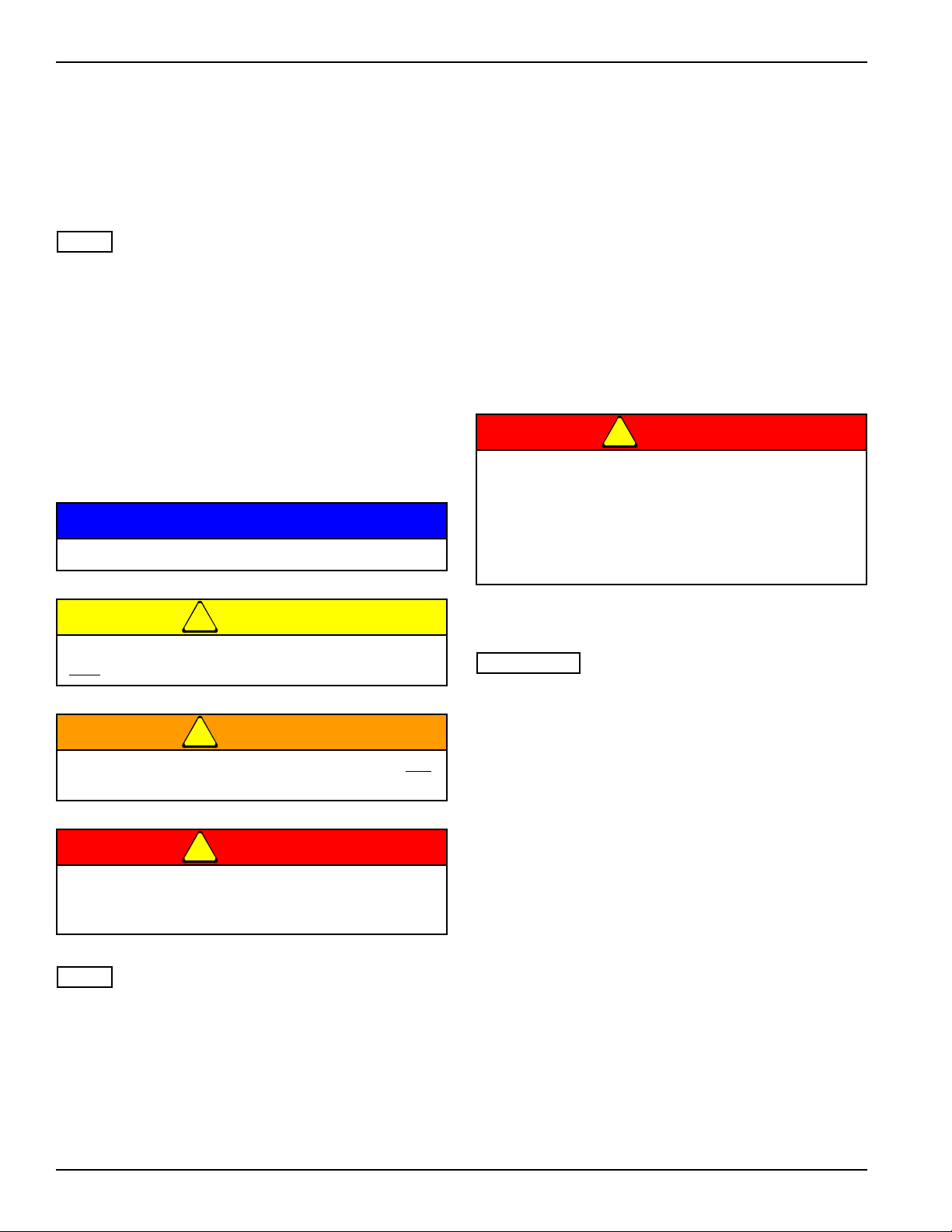
Understanding Safety Statements
You will find various types of safety information on the
following pages and on the machine decals (signs)
attached to the implement. This section explains their
meaning.
Special notice - read and thoroughly understand.
Order replacement decals through your Brillion dealer.
Keep these signs clean so they can be observed readily.
It is important to keep these decals cleaned more
frequently than the machine. Wash with soap and water
or a cleaning solution as required.
Replace decals that become damaged or lost. Also, be
sure that any new machine components installed during
repair include decals which are assigned to them by the
manufacturer.
When applying decals to the machine, be sure to clean
the surface to remove any dirt or residue. Where
possible, sign placement should protect the sign from
abrasion, damage, or obstruction from mud, dirt, oil etc.
Keep Riders Off of Machinery
• Do not allow anyone to ride on tractor or
machine. Riders could be struck by foreign
objects or thrown from the machine.
• Never allow children to operate equipment.
• Keep bystanders away from machine during
operation.
Proceed with caution. Failure to heed caution
cause injury to person or damage product.
may
Proceed with caution. Failure to heed warning will
cause injury to person or damage product.
Proceed with extreme caution. Failure to heed
notice will cause injury or death to person and/or
damage product.
You should read and understand the information
contained in this manual and on the machine decals
before you attempt to operate or maintain this equipment.
Examine safety decals and be sure you have the correct
safety decals for the machine. See Safety Sign and
Locations in Safety Section for decal locations, pages 1-5
and 1-6.
Transporting Safety
It is the responsibility of the owner/operator to
comply with all state and local laws.
When transporting the machine on a road or highway,
use adequate warning symbols, reflectors, lights and
slow moving vehicle sign as required. Slow moving
tractors and towed implements can create a hazard when
driven on public roads. They are difficult to see,
especially at night.
Do not tow an implement that, when fully loaded, weighs
more than 1.5 times the weight of the towing vehicle.
Carry reflectors or flags to mark tractor and implement in
case of breakdown on the road.
Do not transport at speeds over 20 MPH under good
conditions. Never travel at a speed which does not allow
adequate control of steering and stopping. Reduce
speed if towed load is not equipped with brakes
Avoid sudden stops or turns because the weight of the
machine may cause the operator to lose control of the
tractor. Use a tractor heavier than the machine.
Use caution when towing behind articulated steering
tractors; fast or sharp turns may cause the machine to
shift sideways.
1-2 1P342

Keep clear of overhead power lines and other
NOTE
NOTE
obstructions when transporting. Know transport height
and width of your machine. Refer to transport dimensions
page 5-1.
Attaching, Detaching and Storage
• Do not stand between the tractor and implement when
attaching or detaching implement unless both are not
moving.
• Before applying pressure to the hydraulic system, be
sure all connections are tight and that hydraulic lines
and hoses are not damaged.
• Lower machine to ground when not in use so that the
shanks are taking the load.
• Block machine so it will not roll when unhitched from
the tractor.
• Relieve pressure in hydraulic lines before uncoupling
hydraulic hoses from tractor.
SAFETY INFORMATION
On most tractors relieving hydraulic pressure can be
accomplished by operating valves after the engine is
stopped. Also, the machine should be lowered to ground
so that the shanks are taking the load.
Wear protective gloves and safety glasses or goggles
when working with hydraulic systems.
Protective Equipment
• Wear protective clothing & equipment.
• Wear clothing & equipment appropriate for the job.
Avoid loose fitting clothing.
• Because prolonged exposure to loud noise can cause
hearing impairment or hearing loss, wear suitable
hearing protection, such as earmuffs or earplugs.
Chemical Safety
On most tractors relieving hydraulic pressure can be
accomplished by operating valves after the engine is
stopped.
Maintenance Safety
Block the machine so it will not roll when working on or
under it to prevent injury in case of hydraulic failure or
inadvertent lowering by another person.
Do not make adjustments or lubricate machine while it is
in motion.
Make sure all moving parts have stopped and all system
pressure is relieved.
Understand the procedure before doing the work. Use
proper tools and equipment. Refer to “TORQUE
SPECIFIED IN FOOT POUNDS” on page 4-1 for
additional information.
High Pressure Fluid Safety
Escaping fluid under pressure can be nearly invisible and
have enough force to penetrate the skin causing serious
injury. Use a piece of cardboard, rather than hands, to
search for suspected leaks.
Any fluid injected into the skin must be surgically
removed within a few hours or gangrene may result.
Avoid the hazard by relieving pressure before
disconnecting hydraulic lines.
Agricultural chemicals can be dangerous. Improper use
can seriously injure persons, animals, plants, soil &
property.
Read chemical manufacture’s instructions and store or
dispose of unused chemicals as specified. Handle
chemicals with care & avoid inhaling smoke from any
type of chemical fire.
Store or dispose of unused chemicals as specified by the
chemical manufacturer.
Prepare for Emergencies
• Keep a First Aid Kit and Fire Extinguisher handy
• Keep emergency numbers for doctor, ambulance,
hospital and fire department near phone.
Tire Safety
Tire changing can be dangerous and should be
performed by trained personnel using correct tools and
equipment.
When inflating tires, use a clip-on chuck and extension
hose long enough to allow you to stand to one side, not in
front of or over the tire assembly. Use a safety cage if
available.
When removing and installing wheels, use
wheel-handling equipment adequate for weight involved.
Use a safety chain to help control drawn machinery
should it separate from the tractor drawbar.
1-3
SAFETY INFORMATION
Seeder Op SafetyCha
Optional
Hitch
Orientation
Locknut,3/4-10
HHCS,3/4-10 x 2 1/4”
9” Max.
Safety Chain
Flat Washer, 3/4”
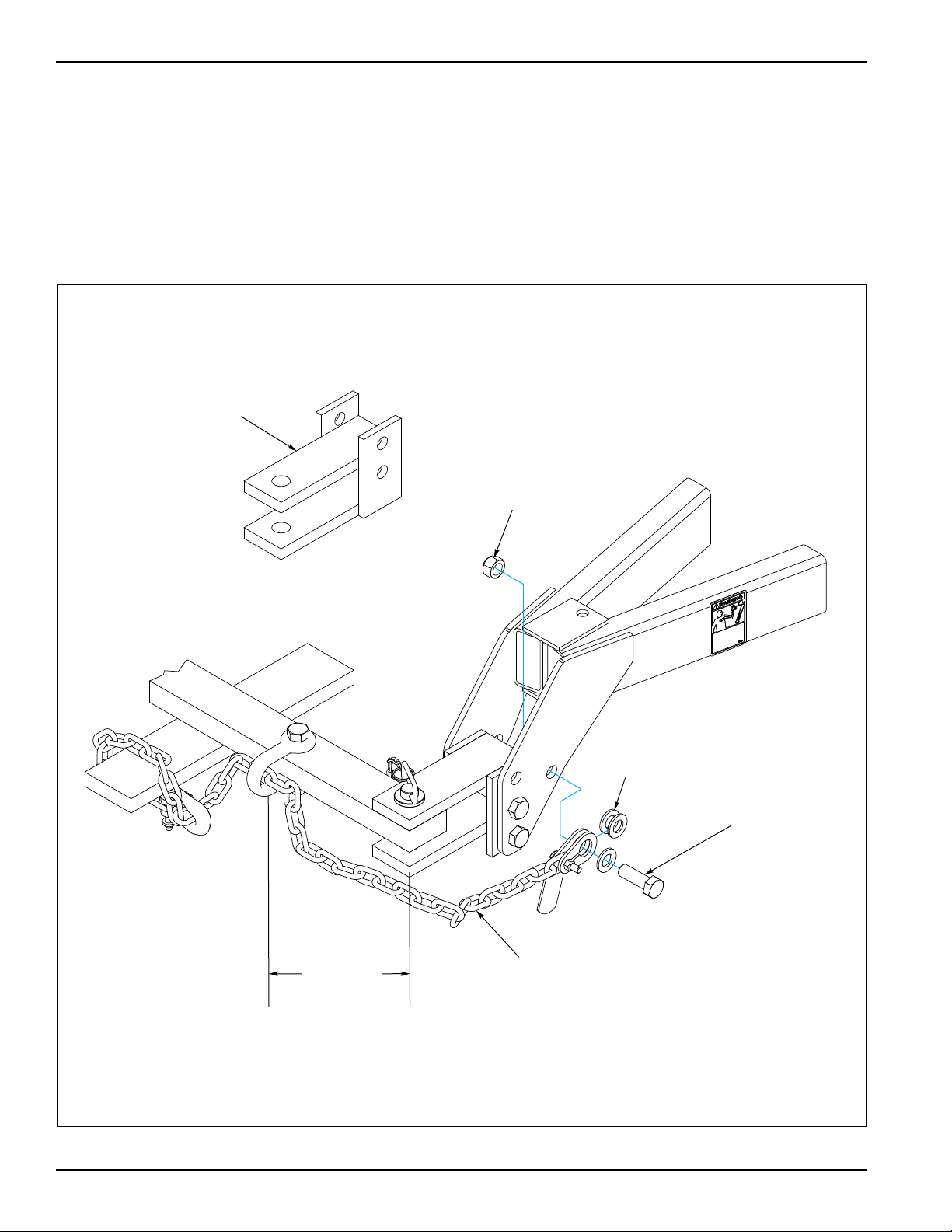
Use a chain with a strength rating equal to or greater than
the gross weight of towed machinery, which is 10,100
pounds minimum in accordance with ASAE S338.2
specifications. If two or more machines are pulled in
tandem, a larger chain may be required. Chain capacity
must be greater that the TOTAL weight of all towed
implements.
A second chain should be used between each
implement.
Attach the chain to the tractor drawbar support or
specified anchor location. Allow only enough slack in the
chain to permit turning. The distance from hitch pin to
attachment point or intermediate support point should not
exceed 9 inches. See Figure 1-2.
Replace chain if any links or end fittings are broken,
stretched or damaged.
Do not use a safety chain for towing.
Figure 1-2: Safety Chain
1-4 1P342

Safety Signs
MOVING MACHINES CAN CAUSE INJURY. KEEP AWAY!
1. KEEP AWAY FROM MOVING TRACTORS OR IMPLEMENTS.
KEEP OTHERS AWAY.
2. DO NOT RIDE OR ALLOW OTHERS TO RIDE ON TRACTOR
OR IMPLEMENT.
3. BLOCK IMPLEMENT TO PREVENT MOVEMENT WHEN
UNHITCHED FROM TRACTOR.
4. KEEP ALL GUARDS AND SHIELDS IN PLACE WHILE MACHINE
OR PARTS ARE IN MOTION.
8J309
!
CAUTION
PA R K I N G P I N
9J301
WARNING
!
DO NOT GO NEAR LEAKS
LOWER LOAD OR RELIEVE HYDRAULIC
PRESSURE BEFORE LOOSENING
FITTINGS.
HIGH PRESSURE OIL EASILY PUNCTURES
SKIN
CAUSING SERIOUS INJURY, GANGRENE
OR DEATH.
IF INJURED, SEEK EMERGENCY MEDICAL
HELP.
IMMEDIATE SURGERY IS REQUIRED TO
REMOVE OIL.
DO NOT USE FINGERS OR SKIN TO
CHECK FOR LEAKS.
10813A
BE SURE TO ENGAGE
PARKING PIN ON LEFT END OF
FRAME BEFORE UNHITCHING
TRACTOR. OTHERWISE
FRAME WILL TIP BACKWARDS
ABOUT FRONT AXLE.
9J302
CAUTION
!
Pick-up only
Pick-up
only
Pull Type only
P/N 3K706
Hydraulic Leak Hazard
P/N 528934
P/N 9J302
Engage Parking Pin
P/N 8J309
List of
Cautions
Reflective Amber
SAFETY INFORMATION
Figure 1-3: Safety Signs (1 of 2)
1-5
SAFETY INFORMATION
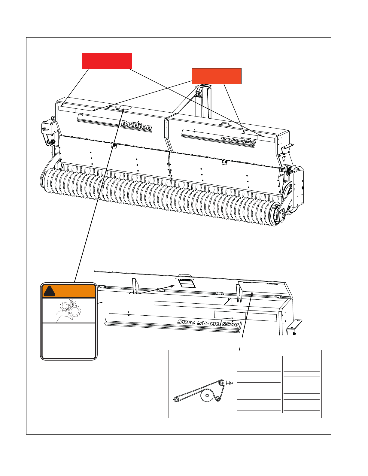
Seed Box May Be Calibrated for Unlisted Seed as Follows:
1. Remove Drive Bolt from 6 Tooth 550 Driver Sprocket.
2. Raise machine & lock in transport position.
3. Place a tarp under machine to collect seed.
4. Turn 15/16 Hex on transmission clockwise as follows:
-136 revolutions - for 8’ Seeders
-109 revolutions - for 10’ Seeders
- 91 revolutions - for 12’ Seeders
5. Weigh seed and multiply by 10 (20 for 26-Tooth Driver)
for approximate planting rate in lbs/acre.
PLANTING RATES FOR SEED BOX
INDICATOR SETTING
POUNDS PER ACRE
POUNDS PER 1000 SQ. FT.
1 2 3 4 5 6 7 8 1 2 3 4 5 6 7 8
9K348C
Tightener
13 Tooth
Idler
37 Tooth
Driven
13 Tooth driver
(26 Tooth Optional)
15/16 Hex
* Will crack some seeds at theses settings.
Not recommended: Lentils, Sorgum, Sudan Grass
WARNING
!
MOVING PART HAZARD
TO PREVENT SERIOUS INJURY
FROM MOVING PARTS:
• KEEP COVERS CLOSED DURING
OPERATION.
• DO NOT ALLOW ANYONE TO RIDE
OR CLIMB ON MACHINE DURING
OPERATION.
•KEEP OBSERVERS AWAY.
2K123
Same poisition
under Both Covers
Right Cover only
P/N 1K123
Moving Part Hazard
P/N 9K348
Seed Chart
P/N 528933
Reflective Red
P/N 528938
Orange Stripe
1-6 1P342
Figure 1-4: Safety Signs (2 of 2)
CAUTION
NOTE
IMPORTANT
NOTE
Do Not Work On Or Under This Machine Unless
U-BOLT, 5/8-11 x 6-11/16 x 5-1/2”
LOCKWASHER, 5/8
NUT, 5/8
3 POINT HITCH
ASSEMBLY
Securely Blocked And Supported By A Hoist Or
Tractor Or By Other Sufficient Means!
Chapter 2
Assembly Instructions
• Park the seeder in a work area that has a level
surface and make sure it is blocked securely so that it
cannot roll.
“Left” and “Right” refer to directions seen as if standing
behind the machine and facing in the direction of forward
travel.
Your exact seeder model may vary slightly from the
illustration. (Additional parts identification and location
can be obtained from reviewing parts catalog 1P341.)
If a pre-assembled component or fastener is temporarily
removed, ensure it is correctly re-installed per these
instructions.
• Check that all working parts move freely, bolts are
tight and cotter pins are spread.
Pick Up Seeder Assembly
When shipped, seeder comes assembled except for
lights and 3 pt. Hitch.
1. Support seeder assembly with a hoist or by similar
means capable of supporting its weight without
tipping.
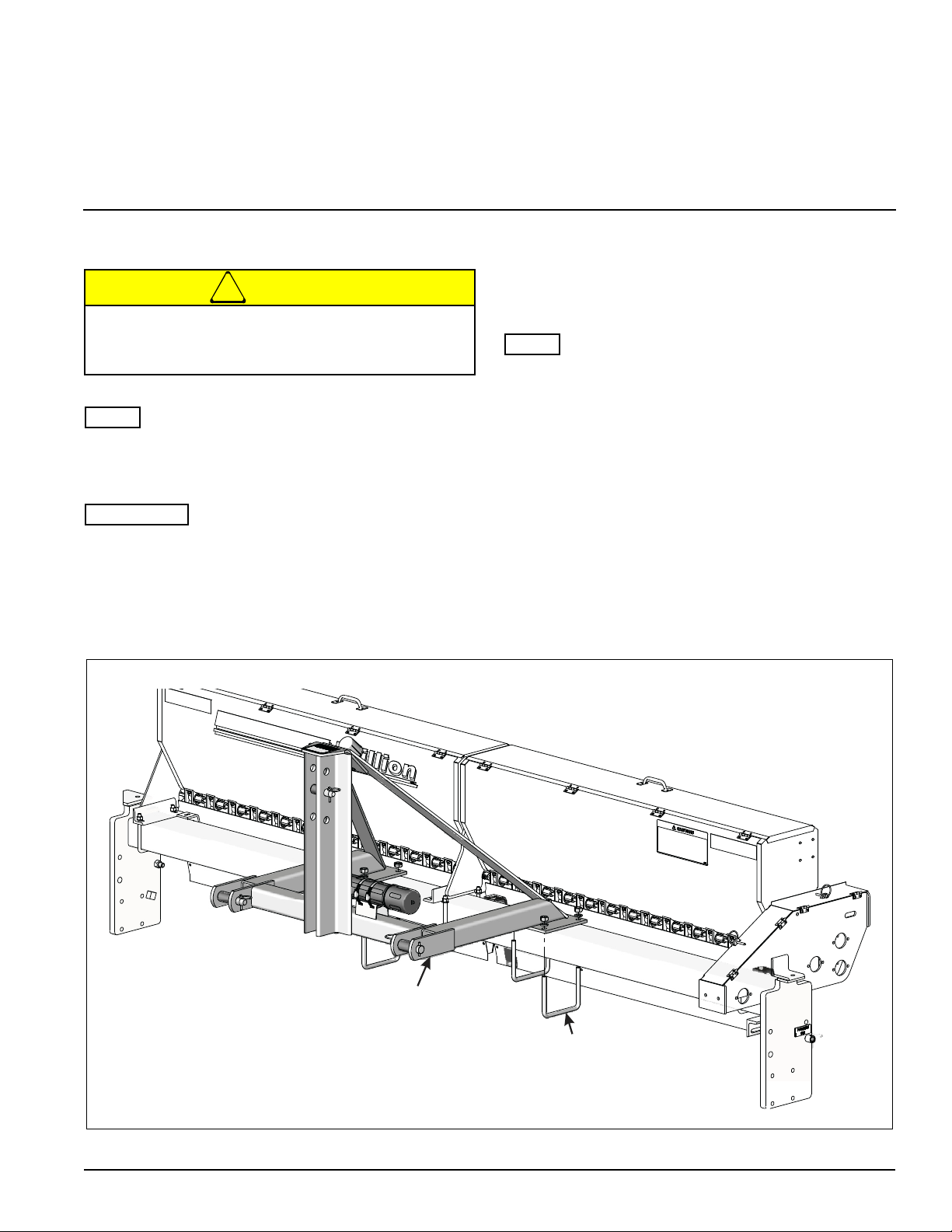
2. Position 3 point hitch assembly on center of frame
and fasten with four 5/8” U-bolts, Lockwashers and
Nuts from bag in seedbox. See Figure 2-1.
Figure 2-1: Attach 3 Pt. Hitch
2-1
ASSEMBLY INSTRUCTIONS
CAUTION
Parking Pin
Shipping Bolt
3. Remove 5/8” shipping bolt from right side of frame
which locks rear roller down. Bolt is located in a
position similar to the parking pin.
4. Install the LED Warning Lamps and Harnesses. See
Figures 2-7, 2-8 and 2-10.
Do not disengage pin unless seeder is fully
attached to a tractor. Seeder may be rear-heavy
and tip backward on frame
Figure 2-2: Shipping Bolt and Parking Pin
2-2 1P342
ASSEMBLY INSTRUCTIONS
NOTE
IMPORTANT
NOTE
U-BOLT,5/8-11
LOCKWASHER,5/8
NUT,5/8
DRAWBAR
HOSE
HHCS,5/8-11 x 1-1/2”
LOCKWASHER,5/8
NUT,5/8-11
SUPPORT
Pull Type Seeder Assembly
Drawbar Assembly
When shipped, seeder comes assembled except for
lights, wheels, and drawbar.
Your exact seeder model may vary slightly from the
illustration. (Additional parts identification and location
can be obtained from reviewing parts catalog 1P341.)
If a pre-assembled component or fastener is temporarily
removed, ensure it is correctly re-installed per these
instructions.
• Check that all working parts move freely, bolts are
tight and cotter pins are spread.
• Park the seeder in a work area that has a level
surface and make sure it is blocked securely so that it
cannot roll.
“Left” and “Right” refer to directions seen as if standing
behind the machine and facing in the direction of forward
travel.
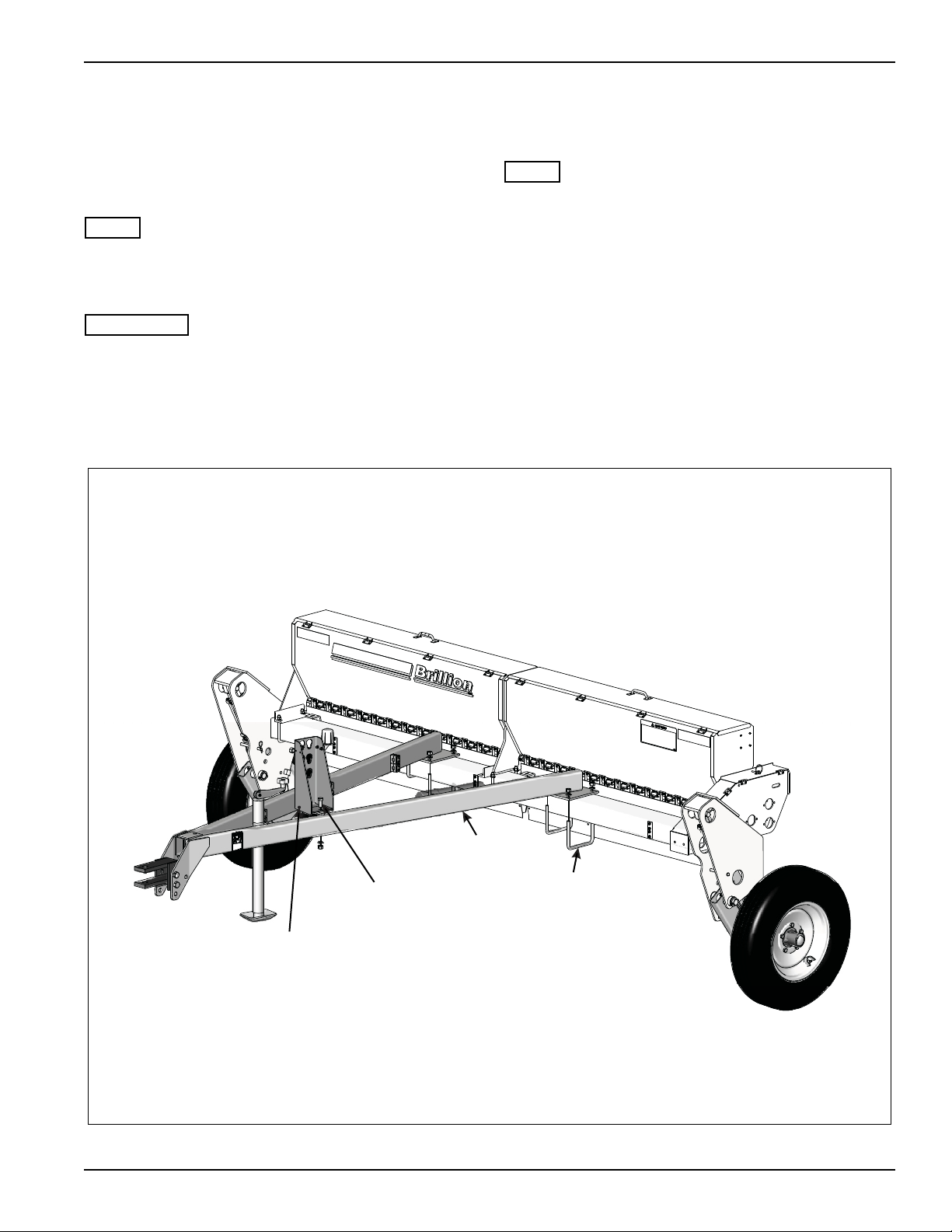
1. Loosen the two rolled up hydraulic hoses from the
front frame shipping position. Ensure the hoses are
not interfering with where the drawbar is to be
attached.
2. Position the drawbar on center of frame and secure
with four 5/8-11 x 6-11/16” x 5-1/2” U-bolts,
Lockwashers, and Nuts from bag in seedbox. See
Figure 2-3.
3. Attach the Hose Support to the Drawbar with 5/8-11
x 1-1/2 Screws, Lockwashers and Nuts.
Figure 2-3: Pull Seeder Drawbar Installation
2-3
ASSEMBLY INSTRUCTIONS
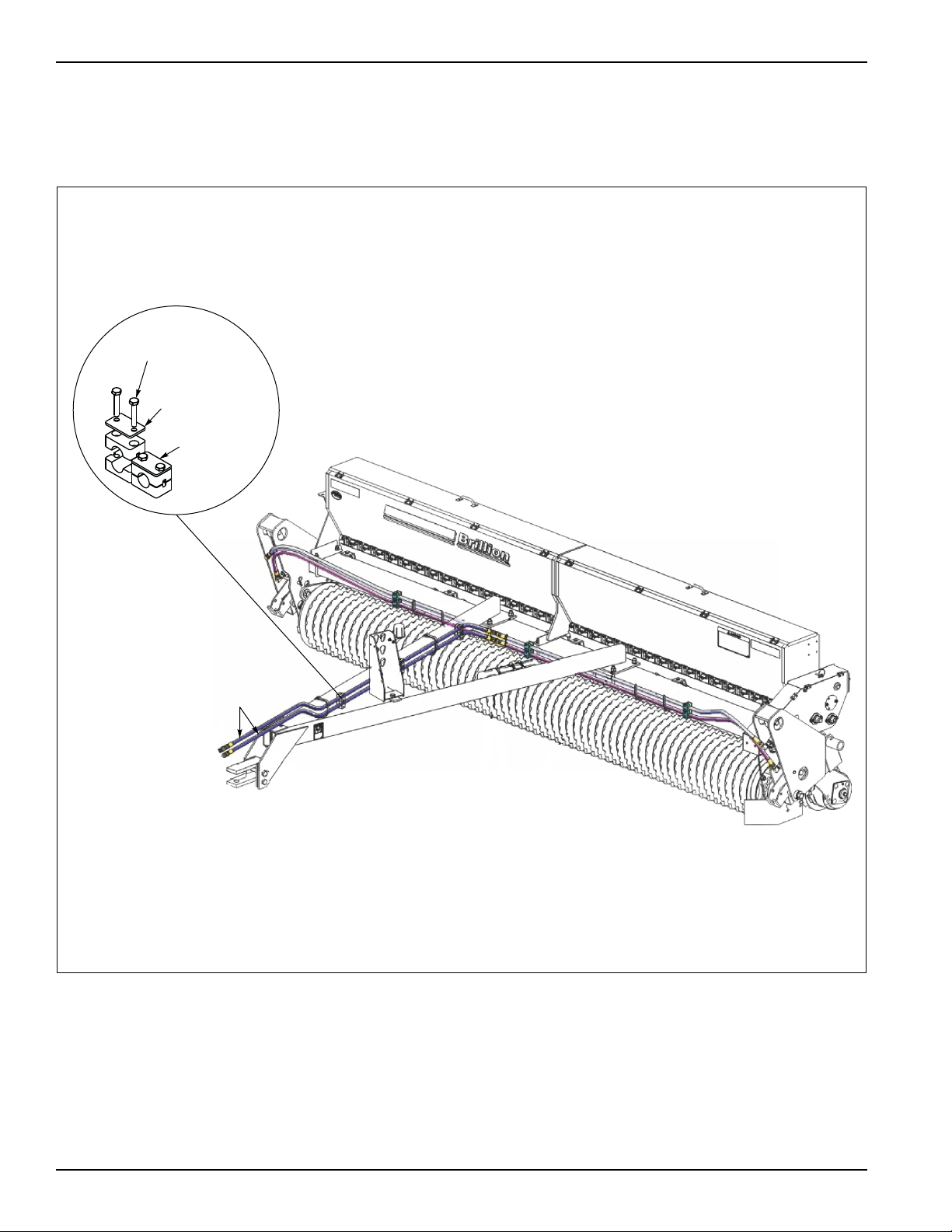
Top Plate
Clamp Pair
HHCS, 1/4-20 x 1/2
Hydraulic
Hoses
4. After the drawbar is attached route the hoses along
drawbar toward the tractor. Use the hose clamps
provided to anchor the hoses to the drawbar. See
Figure 2-4.
Figure 2-4: Drawbar Hydraulic Hoses
5. Install hub and spindles into the wheel arms and
secure in outside hole farthest from the hub. Secure
with 1/2-13 x 3” Screws and Locknuts. See
Figure 2-5.
6. Install wheels and tires to hubs using (10) 1/2-20 x 1
Wheel Bolts.
Charge the Hydraulic System.
For a more detailed view, refer to the Hydraulic
Schematic Diagram. See Figure 4-7.
2-4 1P342
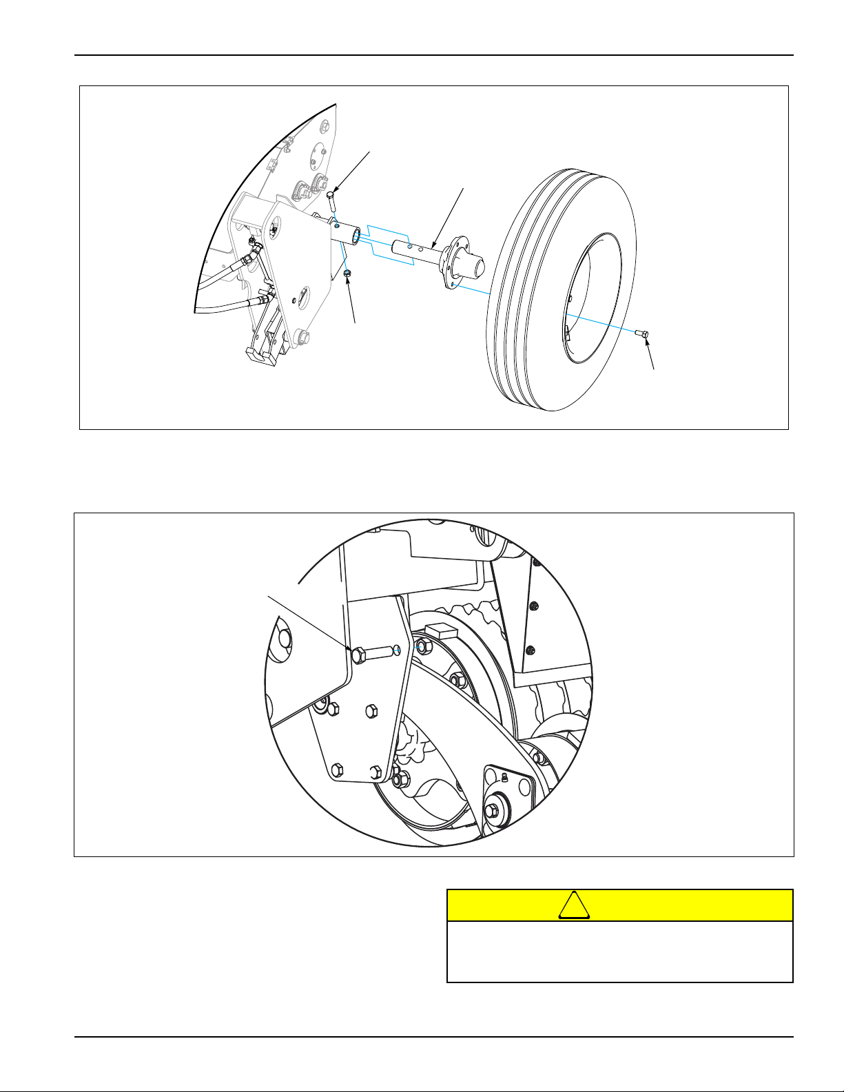
Figure 2-5: Spindle
CAUTION
Op WhlArm9J324HubTire
Wheel Bolt,
1/2-20 x 1”
Locknut,
1/2-13
Spindle
HHCS,1/2-13 x 3”
5/8” SHIPPING
BOLT
ASSEMBLY INSTRUCTIONS
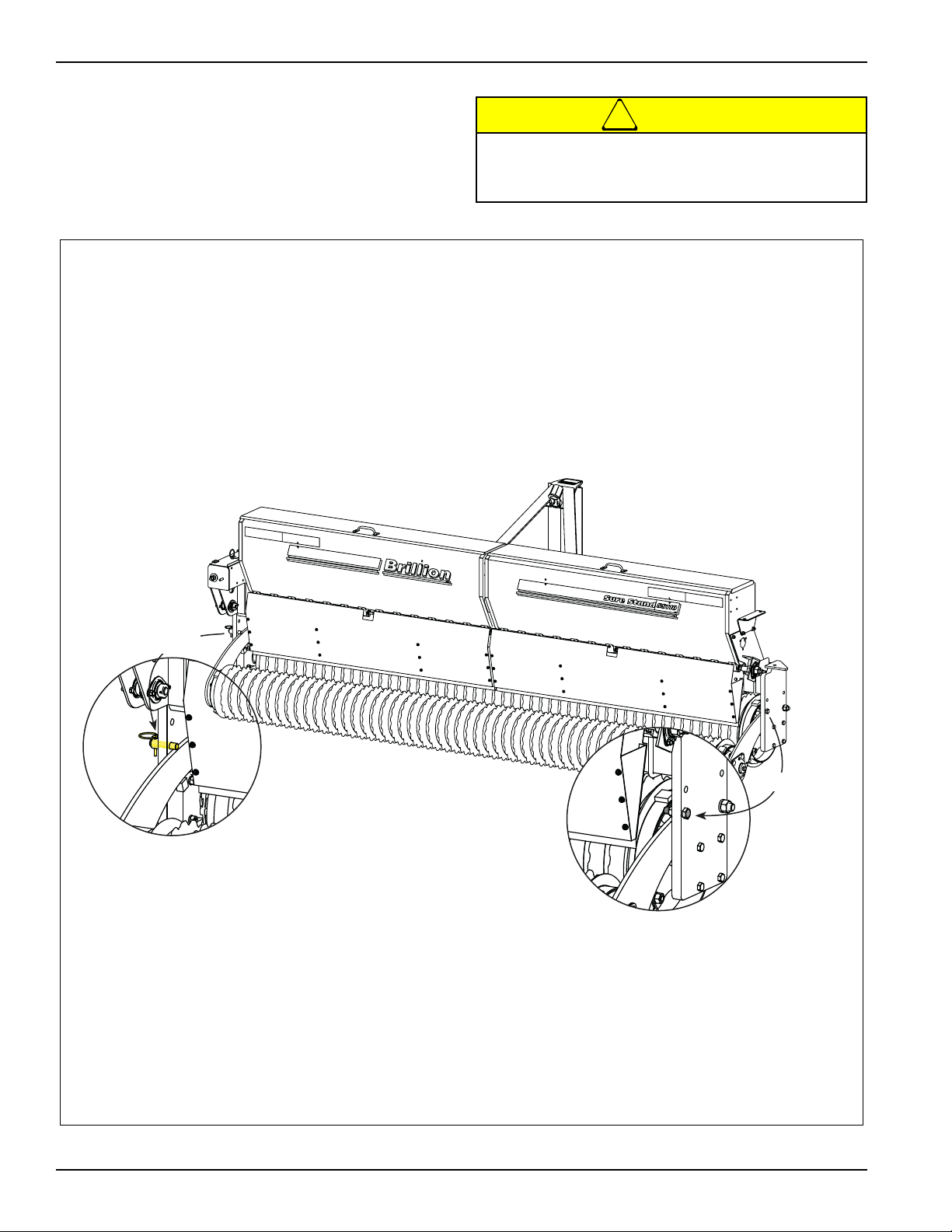
7. Remove the (2) 5/8” shipping bolts which lock the
rear roller arms down. One bolt is used on each side
of the machine. See Figure 2-6.
Figure 2-6: Shipping Bolt
8. Install the LED Warning Lamps and Harnesses. See
Figures 2-7, 2-8 and 2-10.
Do not disengage pin unless seeder is fully
attached to tractor. Seeder may be rear-heavy and
tip backward on frame.
2-5
ASSEMBLY INSTRUCTIONS
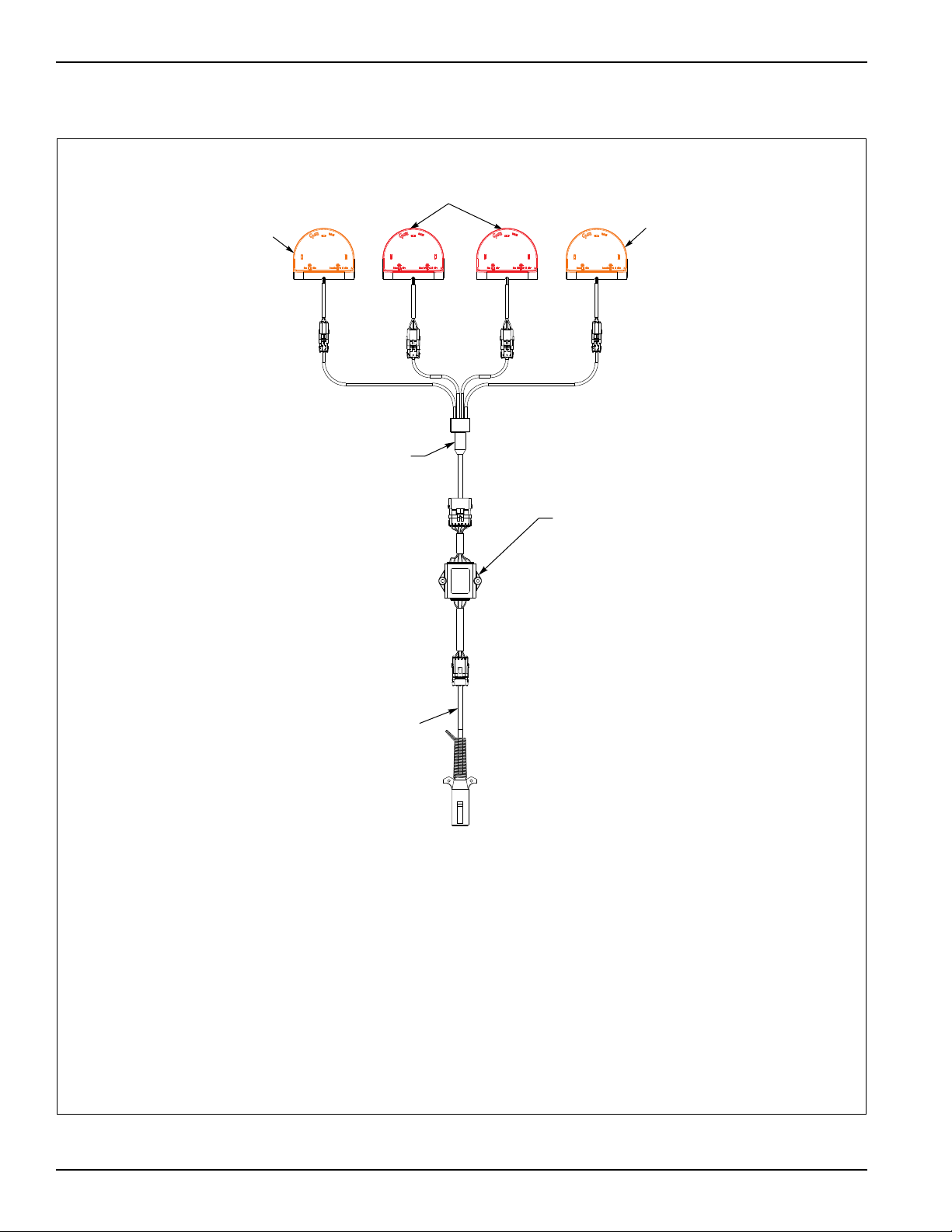
Amber LED Lamp
LED Warning
Lights Harness
Flasher Control
Module
7Pin/4Pin
WP Harness
Red LED Lamp
Amber LED Lamp
When plugging in the LED 7-pin connector:
1) Make sure the tractor has a good clean receptacle, free of dirt and corrosion.
2) Make sure the 7-pin connector is inserted ALL the way in. With tighter fitting pins, operator
may think the connector is all the way in, but really isn’t.
3) Make sure the tractor receptacle cover latches over the keyway on the 7-pin connector to hold
the connector in place.
If an operator plugs in the 7-pin connector, but the lights do not seem to work right, check the above
items to make sure there is a good connection with the 7-pin connector.
LED Warning Lights
Figure 2-7: LED Warning Lights
2-6 1P342

Table provided for general use.
NOTES:
ASSEMBLY INSTRUCTIONS
2-7
 Loading...