

Page 1
LANCOM LW-600
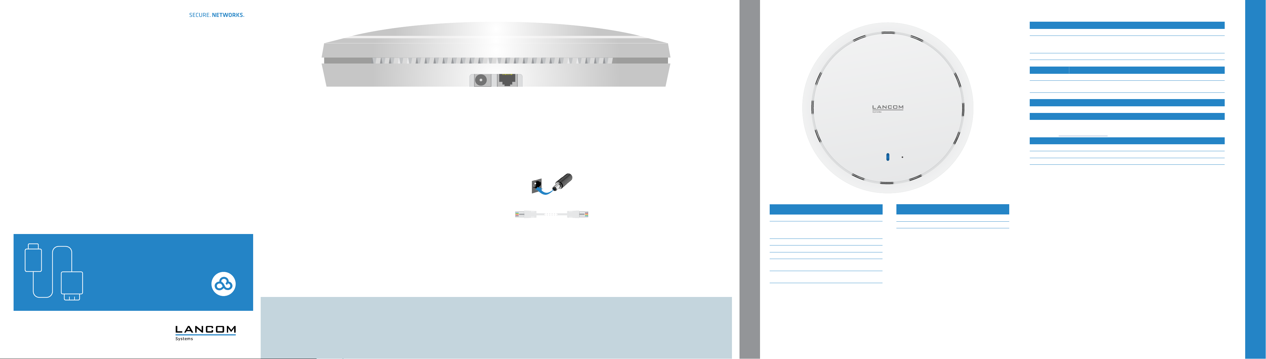
4
Power
a
Supply power to the device using the enclosed power adapter.
Use only the supplied power adapter.
a
b
a b
Hardware
Power supply 12 V DC, external power adapter (110 or 230 V) or PoE as per 802.3af
Power consumption Approx. 11.04 W via 12 V / 1 A power adapter (value solely refers to the power consumption
Environment Temperature range 0 °C to 40 °C; humidity 0-95 %; non-condensing
Housing Robust synthetic housing, ready for wall and ceiling mounting; measures 176 x 30 mm (D x H)
Wi-Fi
Frequency band 2400-2483.5 MHz (ISM) or 5150-5725 MHz (restrictions vary between countries)
Radio channels
2.4 GHz
Radio channels 5 GHz Up to 19 (automatic dynamic channel selection required)
Interfaces
LAN1 (PoE) 10 / 100 / 1000 Base-TX, autosensing, auto node hub, PoE compliant with IEEE 802.3af
Declaration of conformity
Hereby, LANCOM Systems GmbH | Adenauerstrasse 20/B2 | D-52146 Wuerselen, declares that this radio equipment is
in compliance with Directive 2014/53/EU. The full text of the EU declaration of conformity is available at the following
internet address: www.lancom-systems.com/ce/
Package content
Documentation Mounting Instructions (DE/EN)
Mounting material Mounting material for wall- and ceiling mounting
Cable 1 Ethernet cable 1 m
Power adapter External power adapter APD WB-12G12R, 12 V / 1 A DC/S, barrel connector 2.1 / 5.5 mm
of the access point),
approx. 10.9 W via PoE (value solely refers to the power consumption of the access point)
Up to 13 channels, max. 3 non-overlapping (2.4-GHz band)
Quick Reference Guide
Cloud-ready
Ethernet interface
b
Use the enclosed Ethernet cable to connect the Ethernet interface
to your PC or a LAN switch.
Please observe the following when setting up the device
A Do not rest any objects on top of the device
A Keep the ventilation slots on the top of the device clear of obstruction
Before initial startup, please make sure to take notice of the information regarding the intended use in the enclosed installation guide!
Only operate the device with a professionally installed power supply at a nearby socket that is freely accessible at all times.
A In case of wall- or ceiling mounting, use the mounting plate as supplied
a Power
Off Device switched off
Blue, permanently Device operational, resp. device paired /
Blue, blinking Channel search / DFS scan
Red, blinking Hardware failure
Blue / red, alternating DHCP error or DHCP server not accessible
1x blue inverse
blinking
2x blue inverse
blinking
3x blue inverse
blinking
claimed and LANCOM Management Cloud
(LMC) accessible
Connection to the LMC active, pairing OK,
device not claimed
Pairing error, resp. LMC activation code
not available
LMC not accessible, resp. communication
error
MOUNTING AND CONNECTING THE DEVICE
b Reset button
Use a pointed device, e.g. a paper clip for operating the reset button
Pressed up to 5 seconds Device restart
Pressed more than 5
seconds
Conguration reset and device restart
LANCOM, LANCOM Systems, LCOS, LANcommunity and Hyper Integration are registered trademarks. All other names or descriptions used may be trademarks or registered trademarks of their owners. This document
contains statements relating to future products and their attributes. LANCOM Systems reserves the right to change these without notice. No liability for technical errors and / or omissions. 04/20
TECHNICAL DETAILS
 Loading...