

Page 1

... connecting your business
LANCOM GS-2352 User Manual
Page 2

LANCOM GS-2352
Contents
1 Introduction..............................................................................................................................................................7
2 Operation of Web-based Management......................................................................................................................8
3 Configuration..........................................................................................................................................................11
1.1 Overview...................................................................................................................................................7
2.1 Connecting network devices....................................................................................................................10
2.2 Twisted-pair devices................................................................................................................................10
2.3 Cabling guidelines...................................................................................................................................10
3.1 Port.........................................................................................................................................................11
3.1.1 Configuration..........................................................................................................................11
3.1.2 Port Description.......................................................................................................................12
3.1.3 Traffic Overview ......................................................................................................................13
3.1.4 Detailed Statistics ...................................................................................................................14
3.1.5 QoS Statistics ..........................................................................................................................16
3.1.6 SFP Information ......................................................................................................................17
3.2 ACL.........................................................................................................................................................19
3.2.1 Ports........................................................................................................................................19
3.2.2 Rate Limiters...........................................................................................................................20
3.2.3 Access Control List...................................................................................................................21
3.2.4 ACL Status...............................................................................................................................24
3.3 Aggregation............................................................................................................................................26
3.3.1 Static Trunk.............................................................................................................................26
3.3.2 LACP.......................................................................................................................................28
3.4 Spanning Tree.........................................................................................................................................31
3.4.1 Bridge Settings........................................................................................................................31
3.4.2 MSTI Mapping.........................................................................................................................33
3.4.3 MSTI Priorities.........................................................................................................................34
3.4.4 CIST Ports................................................................................................................................35
3.4.5 MSTI Ports...............................................................................................................................37
3.4.6 Bridge Status...........................................................................................................................38
3.4.7 Port Status...............................................................................................................................39
3.4.8 Port Statistics...........................................................................................................................40
3.5 IGMP Snooping.......................................................................................................................................41
3.5.1 Basic Configuration.................................................................................................................41
3.5.2 VLAN Configuration.................................................................................................................43
3.5.3 Port Group Filtering.................................................................................................................44
3.5.4 Status......................................................................................................................................45
3.5.5 Group Information...................................................................................................................47
3.5.6 IPv4 SSM information..............................................................................................................48
3.6 MLD Snooping.........................................................................................................................................49
3.6.1 Basic Configuration.................................................................................................................49
2
Page 3

LANCOM GS-2352
3.6.2 VLAN Configuration.................................................................................................................51
3.6.3 Port Group Filtering.................................................................................................................52
3.6.4 Status......................................................................................................................................53
3.6.5 Group Information...................................................................................................................54
3.6.6 IPv6 SSM Information..............................................................................................................55
3.7 MVR........................................................................................................................................................56
3.7.1 Configuration..........................................................................................................................56
3.7.2 Groups Information.................................................................................................................57
3.7.3 Statistics..................................................................................................................................58
3.8 LLDP........................................................................................................................................................59
3.8.1 LLDP Configuration..................................................................................................................59
3.8.2 LLDP Neighbors.......................................................................................................................61
3.8.3 LLDP-MED Configuration.........................................................................................................63
3.8.4 LLDP-MED Neighbors..............................................................................................................69
3.8.5 EEE..........................................................................................................................................71
3.8.6 Port Statistics...........................................................................................................................73
3.9 Filtering Data Base..................................................................................................................................74
3.9.1 Configuration..........................................................................................................................74
3.9.2 Dynamic MAC Table................................................................................................................76
3.10 VLAN.....................................................................................................................................................78
3.10.1 VLAN Membership ................................................................................................................78
3.10.2 Ports .....................................................................................................................................79
3.10.3 Switch Status ........................................................................................................................80
3.10.4 Port Status.............................................................................................................................81
3.10.5 Private VLANs........................................................................................................................83
3.10.6 MAC-based VLAN..................................................................................................................83
3.10.7 Protocol-based VLAN.............................................................................................................85
3.11 Voice VLAN............................................................................................................................................88
3.11.1 Configuration........................................................................................................................89
3.11.2 OUI........................................................................................................................................90
3.12 GARP.....................................................................................................................................................91
3.12.1 Configuration........................................................................................................................92
3.12.2 Statistics ...............................................................................................................................93
3.13 GVRP.....................................................................................................................................................93
3.13.1 Configuration........................................................................................................................94
3.13.2 Statistics ...............................................................................................................................95
3.14 QoS.......................................................................................................................................................96
3.14.1 Port Classification .................................................................................................................96
3.14.2 Port Policing .........................................................................................................................98
3.14.3 Port Scheduler ......................................................................................................................99
3.14.4 Port Shaping........................................................................................................................102
3.14.5 Port Tag Remarking ............................................................................................................104
3.14.6 Port DSCP............................................................................................................................106
3.14.7 DSCP-Based QoS.................................................................................................................107
3
Page 4

LANCOM GS-2352
4 System Configuration............................................................................................................................................130
5 Security.................................................................................................................................................................152
3.14.8 DSCP Translation ................................................................................................................109
3.14.9 DSCP Classification .............................................................................................................110
3.14.10 QoS Control List Configuration...........................................................................................111
3.14.11 QCL Status ........................................................................................................................114
3.14.12 Storm Control....................................................................................................................116
3.14.13 WRED................................................................................................................................116
3.15 s-Flow Agent.......................................................................................................................................118
3.15.1 Collector .............................................................................................................................118
3.15.2 Sampler ..............................................................................................................................119
3.16 Loop Protection...................................................................................................................................121
3.16.1 Configuration .....................................................................................................................121
3.16.2 Status .................................................................................................................................122
3.17 Easy Port.............................................................................................................................................123
3.18 Mirroring ............................................................................................................................................125
3.19 Trap Event Severity .............................................................................................................................126
3.20 SMTP Configuration ............................................................................................................................127
3.21 UPnP ..................................................................................................................................................128
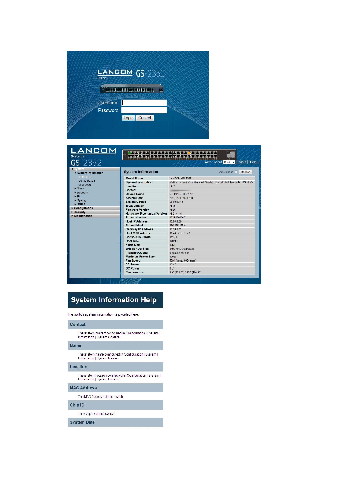
4.1 System Information...............................................................................................................................130
4.1.1 Information...........................................................................................................................130
4.1.2 Configuration........................................................................................................................131
4.1.3 CPU Load...............................................................................................................................132
4.2 Time......................................................................................................................................................133
4.2.1 Manual..................................................................................................................................133
4.2.2 NTP.......................................................................................................................................135
4.3 Account.................................................................................................................................................135
4.3.1 Users.....................................................................................................................................136
4.3.2 Privilege Level........................................................................................................................137
4.4 IP..........................................................................................................................................................138
4.4.1 IPv4 ......................................................................................................................................138
4.4.2 IPv6 ......................................................................................................................................139
4.5 Syslog....................................................................................................................................................140
4.5.1 Configuration........................................................................................................................140
4.5.2 Log........................................................................................................................................141
4.5.3 Detailed Log..........................................................................................................................142
4.6 SNMP....................................................................................................................................................143
4.6.1 System...................................................................................................................................143
4.6.2 Communities.........................................................................................................................144
4.6.3 Users.....................................................................................................................................145
4.6.4 Groups..................................................................................................................................147
4.6.5 Views.....................................................................................................................................148
4.6.6 Access...................................................................................................................................149
4.6.7 Trap.......................................................................................................................................150
4
Page 5

LANCOM GS-2352
5.1 IP Source Guard.....................................................................................................................................152
5.1.1 Configuration........................................................................................................................152
5.1.2 Static Table............................................................................................................................153
5.1.3 Dynamic Table.......................................................................................................................154
5.2 ARP Inspection......................................................................................................................................155
5.2.1 Configuration........................................................................................................................155
5.2.2 Static Table............................................................................................................................156
5.2.3 Dynamic Table.......................................................................................................................157
5.3 DHCP Snooping.....................................................................................................................................157
5.3.1 Configuration........................................................................................................................157
5.3.2 Statistics................................................................................................................................158
5.4 DHCP Relay...........................................................................................................................................160
5.4.1 Configuration........................................................................................................................160
5.4.2 Statistics................................................................................................................................161
5.5 NAS.......................................................................................................................................................162
5.5.1 Configuration........................................................................................................................163
5.5.2 Switch Status.........................................................................................................................169
5.5.3 Port Status.............................................................................................................................170
5.6 AAA.......................................................................................................................................................172
5.6.1 Configuration........................................................................................................................172
5.6.2 Radius Overview....................................................................................................................175
5.6.3 Radius Details........................................................................................................................177
5.7 Port Security..........................................................................................................................................177
5.7.1 Limit Control..........................................................................................................................178
5.7.2 Switch Status.........................................................................................................................180
5.7.3 Port Status.............................................................................................................................181
5.8 Access Management..............................................................................................................................182
5.8.1 Configuration........................................................................................................................182
5.8.2 Statistics................................................................................................................................184
5.9 SSH.......................................................................................................................................................184
5.10 HTTPs..................................................................................................................................................185
5.11 Auth Method.......................................................................................................................................186
6 Maintenance.........................................................................................................................................................187
6.1 Restart Device.......................................................................................................................................187
6.2 Firmware ..............................................................................................................................................187
6.2.1 Firmware Upgrade.................................................................................................................187
6.2.2 Firmware Selection................................................................................................................188
6.3 Save / Restore........................................................................................................................................189
6.3.1 Factory Defaults.....................................................................................................................189
6.3.2 Save Start..............................................................................................................................190
6.3.3 Save User..............................................................................................................................190
6.3.4 Restore User..........................................................................................................................191
6.4 Export / Import......................................................................................................................................191
6.4.1 Export Config.........................................................................................................................191
5
Page 6

LANCOM GS-2352
A. Glossary of Web-based Management...................................................................................................................197
6.4.2 Import Config........................................................................................................................192
6.5 Diagnostics............................................................................................................................................193
6.5.1 Ping.......................................................................................................................................193
6.5.2 Ping6.....................................................................................................................................194
6.5.3 VeriPHY.................................................................................................................................195
C ................................................................................................................................................................197
D ................................................................................................................................................................197
E .................................................................................................................................................................198
F .................................................................................................................................................................198
H ................................................................................................................................................................199
I .................................................................................................................................................................199
L .................................................................................................................................................................200
M ...............................................................................................................................................................201
N ................................................................................................................................................................202
O ................................................................................................................................................................202
P ................................................................................................................................................................203
Q ................................................................................................................................................................204
R ................................................................................................................................................................204
S .................................................................................................................................................................205
T .................................................................................................................................................................206
U ................................................................................................................................................................206
V ................................................................................................................................................................207
6
Page 7

1 Introduction
1.1 Overview
In this user’s manual, it will not only show how to install and connect your network system but how to configure and
monitor the GS-2300 series by (RS-232) serial interface or through the web and ethernet ports step-by-step, too. Many
detailed explanations of hardware and software functions are shown as well as examples of the operation for the
web-based interface.
The GS-2300 series, the next generation of web-managed switches from LANCOM, is a portfolio of affordable managed
switches that provides a reliable infrastructure for your business network. These switches deliver more intelligent features
to improve the availability of your critical business applications, protect your sensitive information, and optimize your
network bandwidth to deliver information and applications more effectively. It provides the ideal combination of
affordability and capabilities for entry level networking includes small business or enterprise application and helps you
create a more efficient, better-connected workforce.
LANCOM GS-2352
1 Introduction
The GS-2352 web managed switch provides 52 ports in a single device. Additional highlights:
L2+ features provide better manageability, security, QoS, and performance.
High port count design with all Gigabit Ethernet ports
Supports guest VLAN, voice VLAN, port-based, tag-based and protocol-based VLANs.
Supports 802.3az energy efficient ethernet standard
Supports 8K MAC table
Supports IPv6/ IPv4 dual stack
Supports s-Flow
Supports Easy-Configuration-Port for easy implementation in the IP Phone, IP Camera or Wireless environment.
7
Page 8

LANCOM GS-2352
2 Operation of Web-based Management
2 Operation of Web-based Management
Initial Configuration
This chapter instructs you how to configure and manage the GS-2300 series through the web user interface. With this
facility, you can easily access and monitor through any one port of the switch all the status of the switch, including MIBs
status, each port activity, spanning tree status, port aggregation status, multicast traffic, VLAN and priority status, illegal
access record, etc.
The default values of the GS-2300 series are listed in the table below:
172.23.56.250IP Address
255.255.255.0Subnet Mask
172.23.56.254Default Gateway
adminUsername
Password
After the switch has finished the configuration of the interface, you can browse it. For instance, type http://172.23.56.250
in the address row in a browser, it will show the following screen and ask you to input your username and password in
order to login and access authentication.
The default username is “admin” and the password is "admin". For the first time, please use the default username and
password, and then click the <Login> button. The login process now is completed. In the login menu, you have to use
the complete username and password respectively, the GS-2300 series will not give you a shortcut to a username
automatically. This looks inconvenient, but is more secure.
In the GS-2300 series, the user management allows only one administrator to configure the system at the same time. If
there are two or more users using administrator access, it will allow the one who logins first to configure the system.
The rest of the users, even with administrator access, can only monitor the system. Those who have no administrator
access can only monitor the system regardless. Only a maximum of three users are able to login simultaneously in the
GS-2300 series.
When you first login on the Switch using the web to manage you must use the Username "admin". Default
5
password is "admin".
Both IPv4 and IPv6 is supported for management functions.
To optimize the display effect, we recommend you use Microsoft IE 6.0 above, Netscape V7.1 above or Firefox
V1.00 above and have a resolution of 1024x768. The switch supports a neutral web browser interface.
admin
The GS-2300 series is set to DHCP by default. If you do not have a DHCP server to provide an ip address to the
5
switch, the default ip is 172.23.56.250
8
Page 9
LANCOM GS-2352
2 Operation of Web-based Management
9
Page 10

LANCOM GS-2352
2 Operation of Web-based Management
2.1 Connecting network devices
The switch is designed to be connected to 10, 100 or 1000Mbps network cards in PCs and servers, as well as to other
switches and hubs. It may also be connected to remote devices using optional SFP transceivers.
2.2 Twisted-pair devices
Each device requires an unshielded twisted-pair (UTP) cable with RJ45 connectors at both ends. Use Category 5, 5e or
6 cable for 1000BASE-T connections, Category 5 or better for 100BASE-TX connections.
2.3 Cabling guidelines
The RJ45 ports on the switch support automatic MDI/MDI-X pin-out configuration, so you can use standard straight-through
twisted-pair cables to connect to any other network device (PCs, servers, switches, routers, or hubs).
See Appendix B for further information on cabling.
CAUTION: Do not plug a phone jack connector into an RJ45 port. This will damage the switch. Use only twisted-pair
5
cables with RJ45 connectors that conform to FCC standards.
CONNECTING TO PCS, SERVERS, HUBS AND SWITCHES
Step 1: Attach one end of a twisted-pair cable segment to the device’s RJ45 connector.
Figure 16: Making Twisted-Pair Connections
Step 2: If the device is a network card and the switch is in the wiring closet, attach the other end of the cable segment
to a modular wall outlet that is connected to the wiring closet. (See the section “Network Wiring Connections.”) Otherwise,
attach the other end to an available port on the switch.
Make sure each twisted pair cable does not exceed 100 meters (328 ft) in length.
Avoid using flow control on a port connected to a hub unless it is actually required to solve a problem. Otherwise
5
back pressure jamming signals may degrade overall performance for the segment attached to the hub.
Step 3: As each connection is made, the Link LED (on the switch) corresponding to each port will light green (1000 Mbps)
or amber (100 Mbps) to indicate that the connection is valid.
NETWORK WIRING CONNECTIONS
Today, the patch-down block is an integral part of many of the newer equipment racks. It is actually part of the patch
panel. Instructions for making connections in the wiring closet with this type of equipment follows.
10
Step 1: Attach one end of a patch cable to an available port on the switch, and the other end to the patch panel.
Step 2: If not already in place, attach one end of a cable segment to the back of the patch panel where the punch-down
block is located, and the other end to a modular wall outlet.
Step 3: Label the cables to simplify future troubleshooting. See “Cable Labeling and Connection Records” .
Figure 17: Network Wiring Connections
Page 11
3 Configuration
This chapter describes all of the basic network configuration tasks which include the Ports, Layer 2 network protocol
(e.g. VLANs, QoS, IGMP, ACLs, and PoE, etc.) and any setting of the Switch.
3.1 Port
The section describes how to configure the Port detail parameters of the switch. You can use the Port configuration to
monitor, enable, or disable the ports of the switch.
3.1.1 Configuration
This chapter describes how to view the current port configuration and how to configure ports to non-default settings,
including
LANCOM GS-2352
3 Configuration
Linkup/Linkdown
Speed (Current and configured)
Flow Control (Current Rx, Current Tx and Configured)
Maximum Frame Size
Excessive Collision Mode
Power Control.
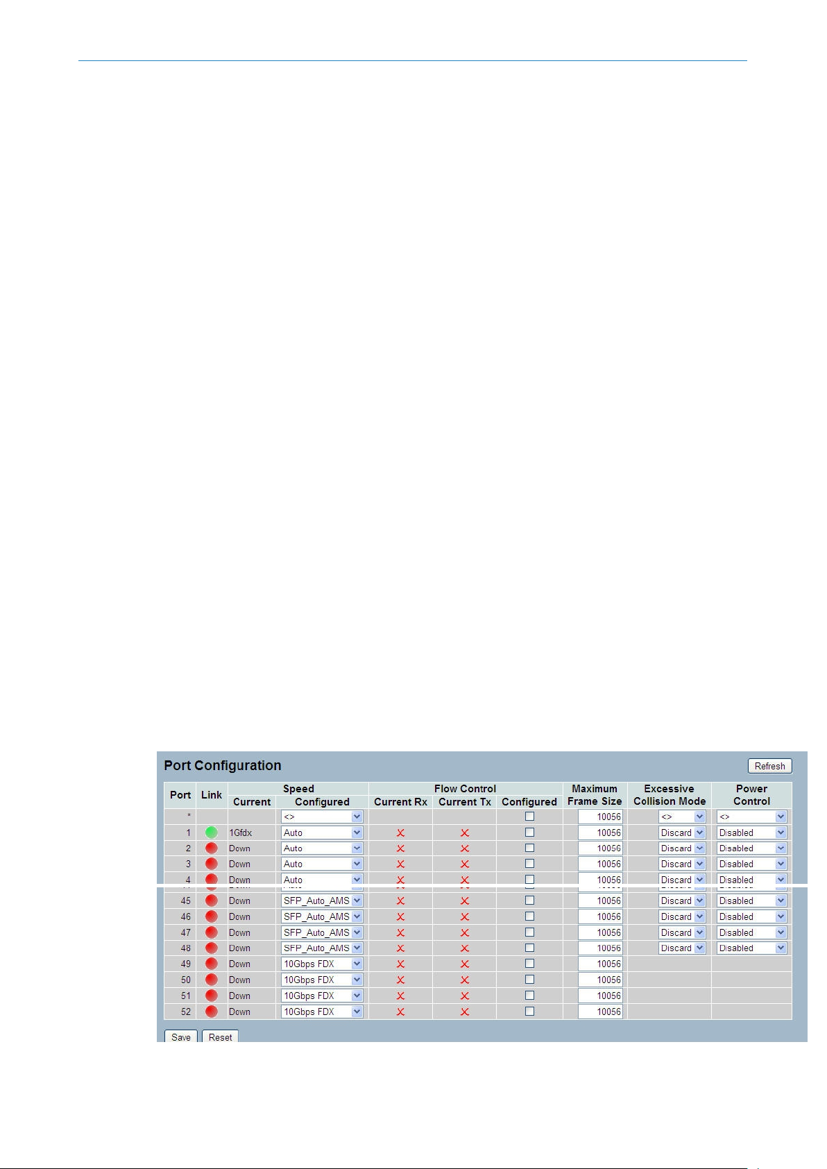
Web Interface
To configure a Port in the web interface:
1. Click Configuration, Port, then Configuration
2. Specify the Speed Configured, Flow Control, Maximum Frame size, Excessive Collision mode, and Power Control.
3. Click Save.
Figure 3-1.1: The Port Configuration
11
Page 12

LANCOM GS-2352
3 Configuration
Parameter description:
Port:
The logical port number for this row.
Link:
The current link state is displayed graphically. Green indicates the link is up and red that it is down.
Current Link Speed:
Provides the current link speed of the port.
Configured Link Speed:
Select any available link speed for the given switch port.
Auto Speed selects the highest speed that is compatible with a link partner.
Disabled disables the switch port operation.
Flow Control:
When Auto Speed is selected on a port, this section indicates the flow control capability that is advertised to the link
partner. When a fixed-speed setting is selected, that is what is used. The Current Rx column indicates whether pause
frames on the port are obeyed, and the Current Tx column indicates whether pause frames on the port are transmitted.
The Rx and Tx settings are determined by the result of the last Auto-Negotiation.
Check the configured column to use flow control. This setting is related to the setting for Configured Link Speed.
Maximum Frame Size:
Enter the maximum frame size allowed for the switch port, including FCS.
Excessive Collision Mode:
Configure port transmit collision behavior.
Discard: Discard frame after 16 collisions (default).
Restart: Restart backoff algorithm after 16 collisions.
Power Control:
The Usage column shows the current percentage of the power consumption per port. The Configured column allows for
changing the power savings mode parameters per port.
Disabled: All power savings mechanisms disabled.
ActiPHY: Link down power savings enabled.
PerfectReach: Link up power savings enabled.
Enabled: Both link up and link down power savings enabled.
Buttons:
Save – Click to save changes.
Reset – Click to undo any changes made locally and revert to previously saved values.
Refresh – Refresh the ports link status manually
3.1.2 Port Description
This section describes how to configure the port’s alias or any descriptions for the ports identity. It provides user the
option to enter an alphanumeric string describing the full name and/or additional information, eg the usage of the port.
Web Interface
12
Page 13
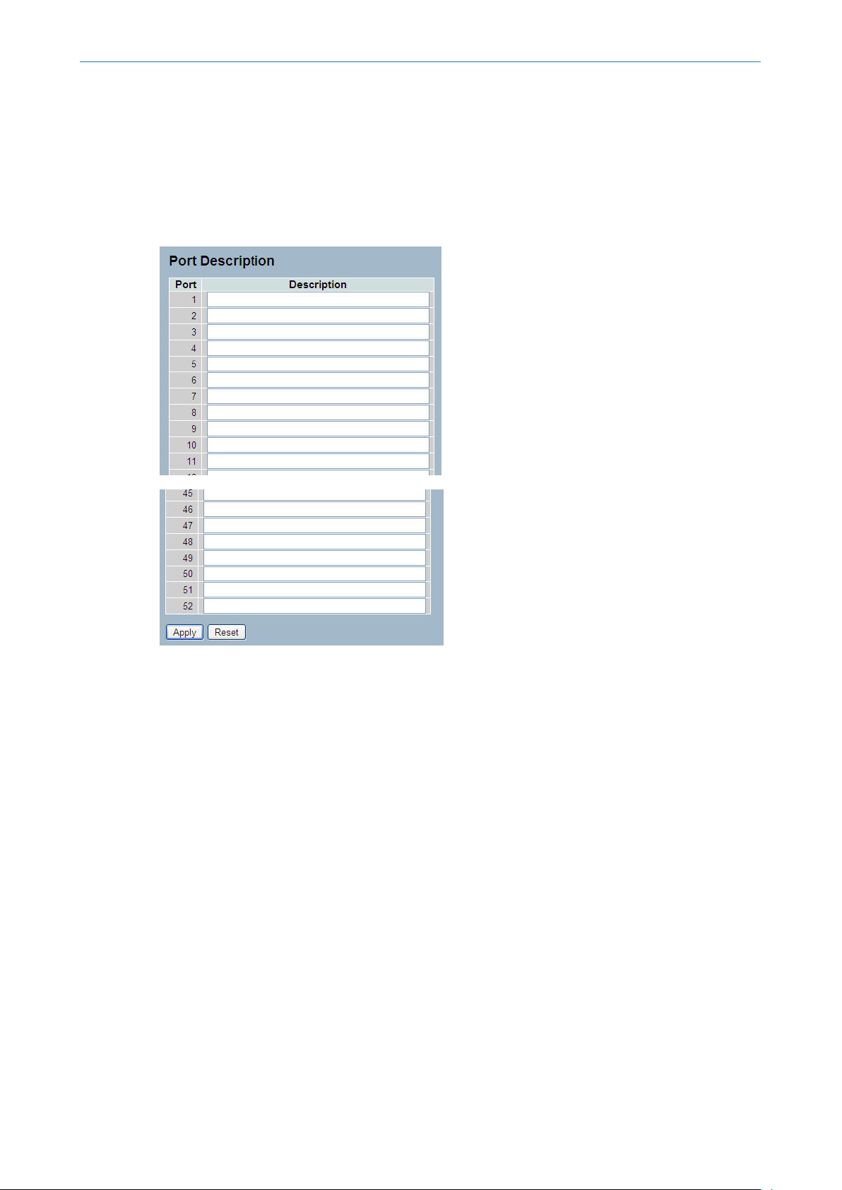
To enter a Port Description in the web interface:
1. Click Configuration, Port, then Port Description
2. Specify the detail port alias or description.
3. Click Save.
Figure 3-1.2: The Port Configuration
LANCOM GS-2352
3 Configuration
Parameter description:
Port:
The logical port number for this row.
Description:
The description of device ports must not include “ # % & ‘ + \.
Buttons
Apply – Click to save changes.
Reset – Click to undo any changes made locally and revert to previously saved values.
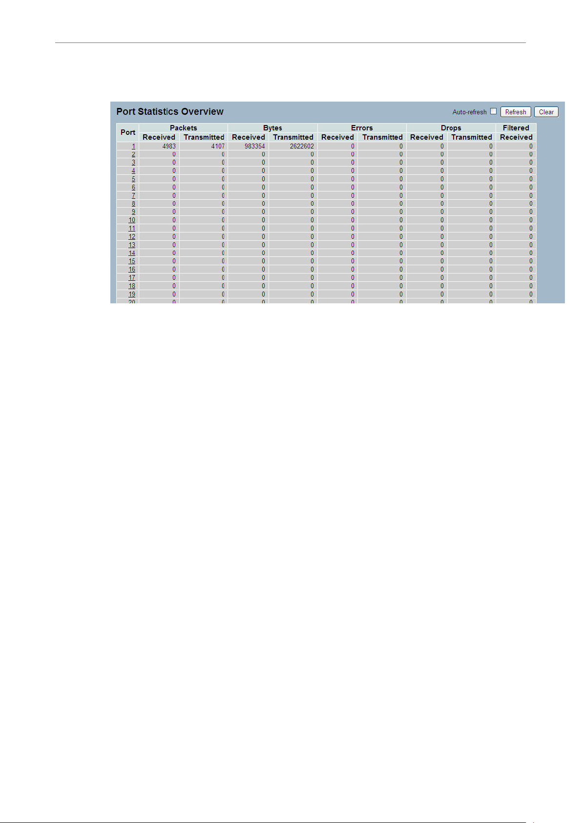
3.1.3 Traffic Overview
This section describes the port statistics information and provides an overview of general traffic statistics for all switch
ports.
Web Interface
To display the Port Statistics Overview in the web interface:
1. Click Configuration, Port, then Traffic Overview
2. If you want to auto-refresh, you need to activate “Auto-refresh”.
3. Click "Refresh" to refresh the port statistics or click "Clear" to clear all information.
13
Page 14
LANCOM GS-2352
3 Configuration
Figure 3-1.3: The Port Statistics Overview
Parameter description:
Port
The logical port for the settings contained in the same row.
Packets
The number of received and transmitted packets per port.
Bytes
The number of received and transmitted bytes per port.
Errors
The number of frames received in error and the number of incomplete transmissions per port.
Drops
The number of frames discarded due to ingress or egress congestion.
Filtered
The number of received frames filtered by the forwarding
Auto-refresh
Activate the auto-refresh to refresh the information automatically.
Refresh
Refresh the Port Statistics information.
Clear
Clean up all Port Statistics.
3.1.4 Detailed Statistics
The section describes how to provide detailed traffic statistics for a specific switch port. Use the port select box to select
which switch port details to display.
The displayed counters are the totals for receive and transmit, the size counters for receive and transmit, and the error
counters for receive and transmit.
14
Page 15
Web Interface
To display the per Port detailed Statistics Overview in the web interface:
1. Click Configuration, Port, then Detailed Port Statistics
2. Scroll the Port Index to select which port you want to show the detailed Port statistics overview.
3. If you want to auto-refresh the information then you need to activate “Auto-refresh”.
4. Click “ Refresh“ to refresh the port detailed statistics or click "Clear" to clear all information.
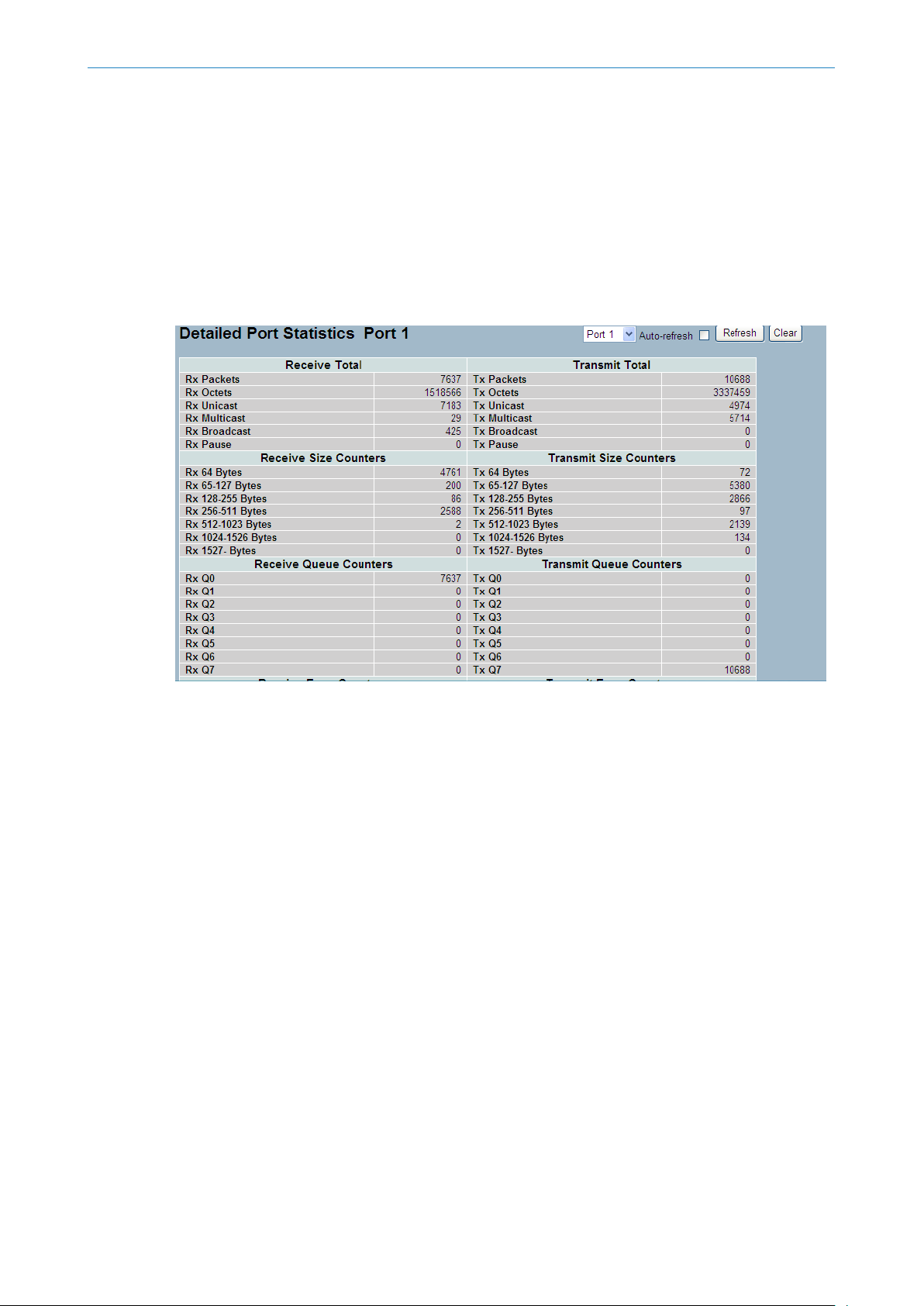
Figure 3-1.4: The Detailed Port Statistics
LANCOM GS-2352
3 Configuration
Parameter description:
Auto-refresh:
To activate the auto-refresh to refresh the Port Statistics information automatically.
Upper left scroll bar:
To scroll which port to display the Port statistics with “Port-0”, “Port-1...
Receive Total and Transmit Total
Rx and Tx Packets:
The number of received and transmitted (good and bad) packets.
Rx and Tx Octets:
The number of received and transmitted (good and bad) bytes. Includes FCS, but excluding framing bits.
Rx and Tx Unicast
The number of received and transmitted (good and bad) unicast packets.
Rx and Tx Multicast:
The number of received and transmitted (good and bad) multicast packets.
Rx and Tx Broadcast:
The number of received and transmitted (good and bad) broadcast packets.
Rx and Tx Pause:
15
Page 16

LANCOM GS-2352
3 Configuration
A count of the MAC Control frames received or transmitted on this port that have an opcode indicating a PAUSE operation.
Receive and Transmit Size Counters
The number of received and transmitted (good and bad) packets split into categories based on their respective frame
sizes.
Receive and Transmit Queue Counters
The number of received and transmitted packets per input and output queue.
Receive Error Counters
Rx Drops:
The number of frames dropped due to lack of receive buffers or egress congestion.
Rx CRC/Alignment:
The number of frames received with CRC or alignment errors.
Rx Undersize:
The number of short 1 frames received with valid CRC.
Rx Oversize:
The number of long 2 frames received with valid CRC.
Rx Fragments:
The number of short 1 frames received with invalid CRC.
Rx Jabber:
The number of long 2 frames received with invalid CRC.
Rx Filtered:
The number of received frames filtered by the forwarding process.
Short frames are frames that are smaller than 64 bytes.
Long frames are frames that are longer than the configured maximum frame length for this port.
Transmit Error Counters
Tx Drops:
The number of frames dropped due to output buffer congestion.
Tx Late/Exc. Coll.:
The number of frames dropped due to excessive or late collisions.
Auto-refresh:
To activate the auto-refresh to refresh the Queuing Counters automatically.
Refresh
Refresh the detailed port statistics manually.
Clear
Clear the detailed port statistics manually.
3.1.5 QoS Statistics
The section describes that switch could display the QoS detailed Queuing counters for a specific switch port. for the
different queues for all switch ports.
16
Page 17
Web Interface
To display the Queuing Counters in the web interface:
1. Click Configuration, Port, then QoS Statistics
2. If you want to auto-refresh the information then you need to activate “Auto-refresh”.
3. Click “ Refresh“ to refresh the Queuing Counters or click "Clear" to clear all information.
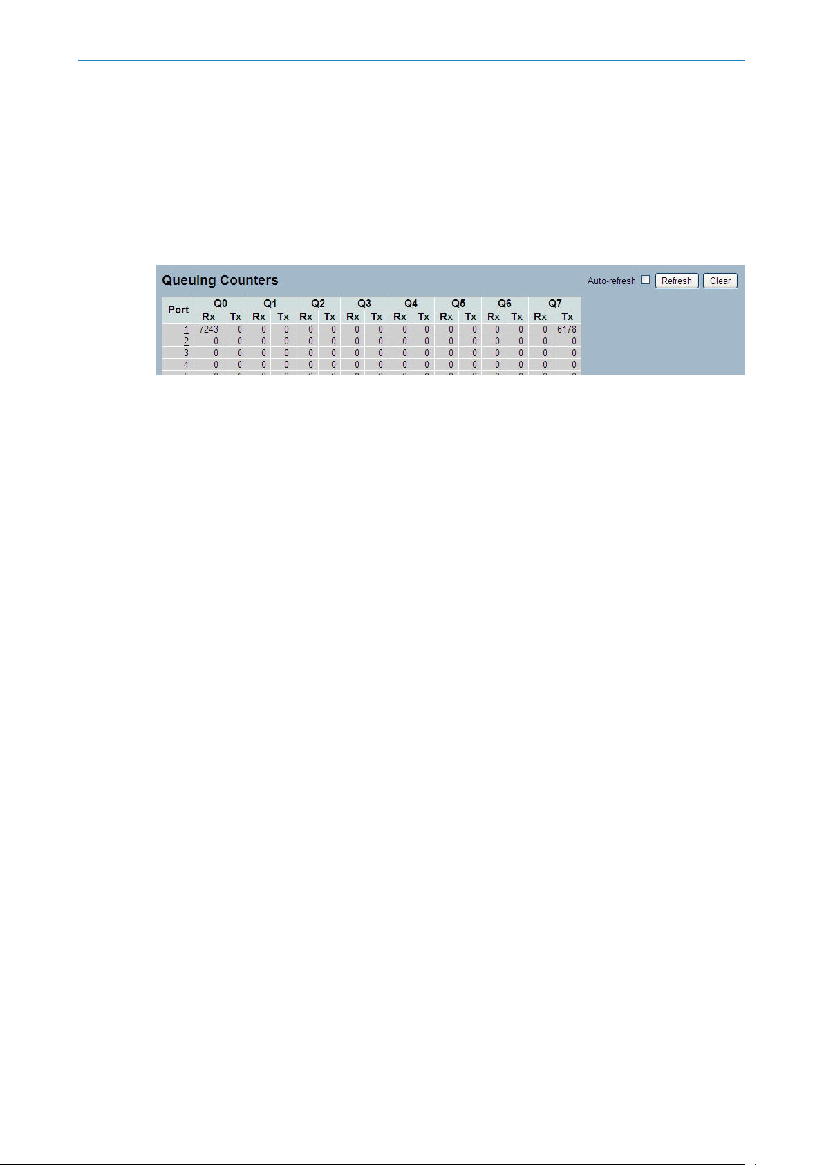
Figure 3-1.5: The Queuing Counters Overview
Parameter description:
Port:
The logical port for the settings contained in the same row.
LANCOM GS-2352
3 Configuration
Qn:
Qn is the Queue number, QoS queues per port. Q0 is the lowest priority queue.
Rx/Tx:
The number of received and transmitted packets per queue.
Auto-refresh:
To activate the auto-refresh to refresh the Queuing Counters automatically.
Refresh
Refresh the Queuing Counters manually.
Clear
Clear the Queuing Counters manually.
3.1.6 SFP Information
The section describes the SFP module information which you will see when you connect an SFP module to the switch.
The information includes: Connector type, Fiber type, wavelength, baud rate and Vendor OUI etc.
Web Interface
To display the SFP information in the web interface:
1. Click Configuration, Port, then SFP Information
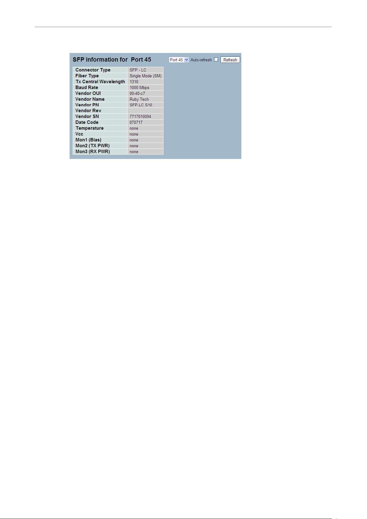
Figure 3-1.6: The SFP Information Overview
17
Page 18
LANCOM GS-2352
3 Configuration
Parameter description:
Connector Type:
Display the connector type, for instance, UTP, SC, ST, LC and so on.
Fiber Type:
Display the fiber mode, for instance, Multi-Mode, Single-Mode.
Tx Central Wavelength:
Display the fiber optical transmitting central wavelength, for instance, 850nm, 1310nm, 1550nm and so on.
Baud Rate:
Display the maximum baud rate of the fiber module supported, for instance, 10M, 100M, 1G and so on.
Vendor OUI:
Display the Manufacturer's OUI code which is assigned by IEEE.
Vendor Name:
Display the company name of the module manufacturer.
Vendor P/N:
Display the product name of the naming by module manufacturer.
Vendor Rev (Revision):
Display the module revision.
Vendor SN (Serial Number):
Show the serial number assigned by the manufacturer.
Date Code:
18
Show the date this SFP module was made.
Temperature:
Show the current temperature of SFP module.
Vcc:
Show the working DC voltage of SFP module.
Mon1(Bias) mA:
Show the Bias current of SFP module.
Mon2(TX PWR):
Page 19
3.2 ACL
3.2.1 Ports
LANCOM GS-2352
3 Configuration
Show the transmit power of SFP module.
Mon3(RX PWR):
Show the receiver power of SFP module.
The GS-2300 series access control list (ACL) is probably the most commonly used object in the IOS. It is used for packet
filtering but also for selecting types of traffic to be analyzed, forwarded, or influenced in some way. The ACLs are divided
into EtherTypes. IPv4, ARP protocol, MAC and VLAN parameters etc. Here we will just go over the standard and extended
access lists for TCP/IP. As you create ACEs for ingress classification, you can assign a policy for each port, the policy
number is 1-8. However, each policy can be applied to any port. This makes it very easy to determine what type of ACL
policy you will be working with.
The section describes how to configure the ACL parameters (ACE) of the each switch port. These parameters will affect
frames received on a port unless the frame matches a specific ACE.
Web Interface
To configure the ACL Ports in the web interface:
1. Click Configuration, ACL, then Ports
2. To scroll the specific parameter value to select the correct value for port ACL setting.
3. Click save to save the setting
4. If you want to cancel the setting then you need to click the reset button. It will revert to previously saved values.
5. After your configuration is complete you can see the counter of the port. Then you could click refresh to update the
counter or clear the information.
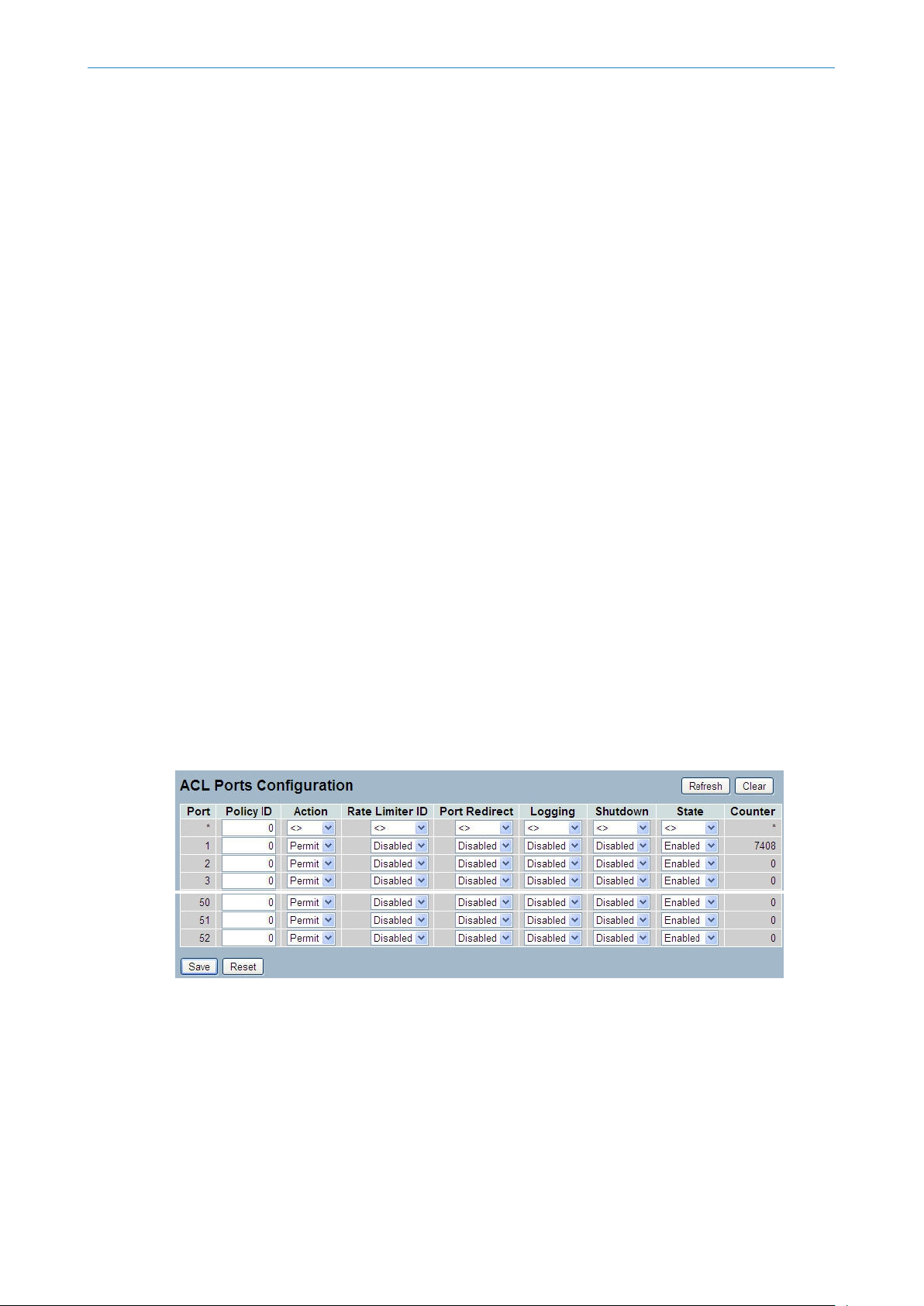
Figure 3-2.1: The ACL Ports Configuration
Parameter description:
Port:
The logical port for the settings contained in the same row.
Policy ID:
Select the policy to apply to this port. The allowed values are 1 through 8. The default value is 1.
Action:
19
Page 20

LANCOM GS-2352
3 Configuration
Select whether forwarding is permitted ("Permit") or denied ("Deny"). The default value is "Permit".
Rate Limiter ID:
Select which rate limiter to apply on this port. The allowed values are Disabled or the values 1 through 16. The default
value is "Disabled".
Port Copy:
Select which port frames are copied on. The allowed values are Disabled or a specific port number. The default value is
"Disabled".
Mirror:
Specify the mirror operation of this port. The allowed values are:
Enabled: Frames received on the port are mirrored.
Disabled: Frames received on the port are not mirrored.
The default value is "Disabled".
Logging:
Specify the logging operation of this port. The allowed values are:
Enabled: Frames received on the port are stored in the System Log.
Disabled: Frames received on the port are not logged.
The default value is "Disabled". Please note that the System Log memory size and logging rate is limited.
Shutdown:
Specify the port shut down operation of this port. The allowed values are:
Enabled: If a frame is received on the port, the port will be disabled.
Disabled: Port shut down is disabled.
The default value is "Disabled".
Counter:
Counts the number of frames that match this ACE.
Buttons
Save – Click to save changes.
Reset – Click to undo any changes made locally and revert to previously saved values.
Refresh
Refresh the ACL Port Configuration manually.
Clear
Clear the ACL Port Configuration manually.
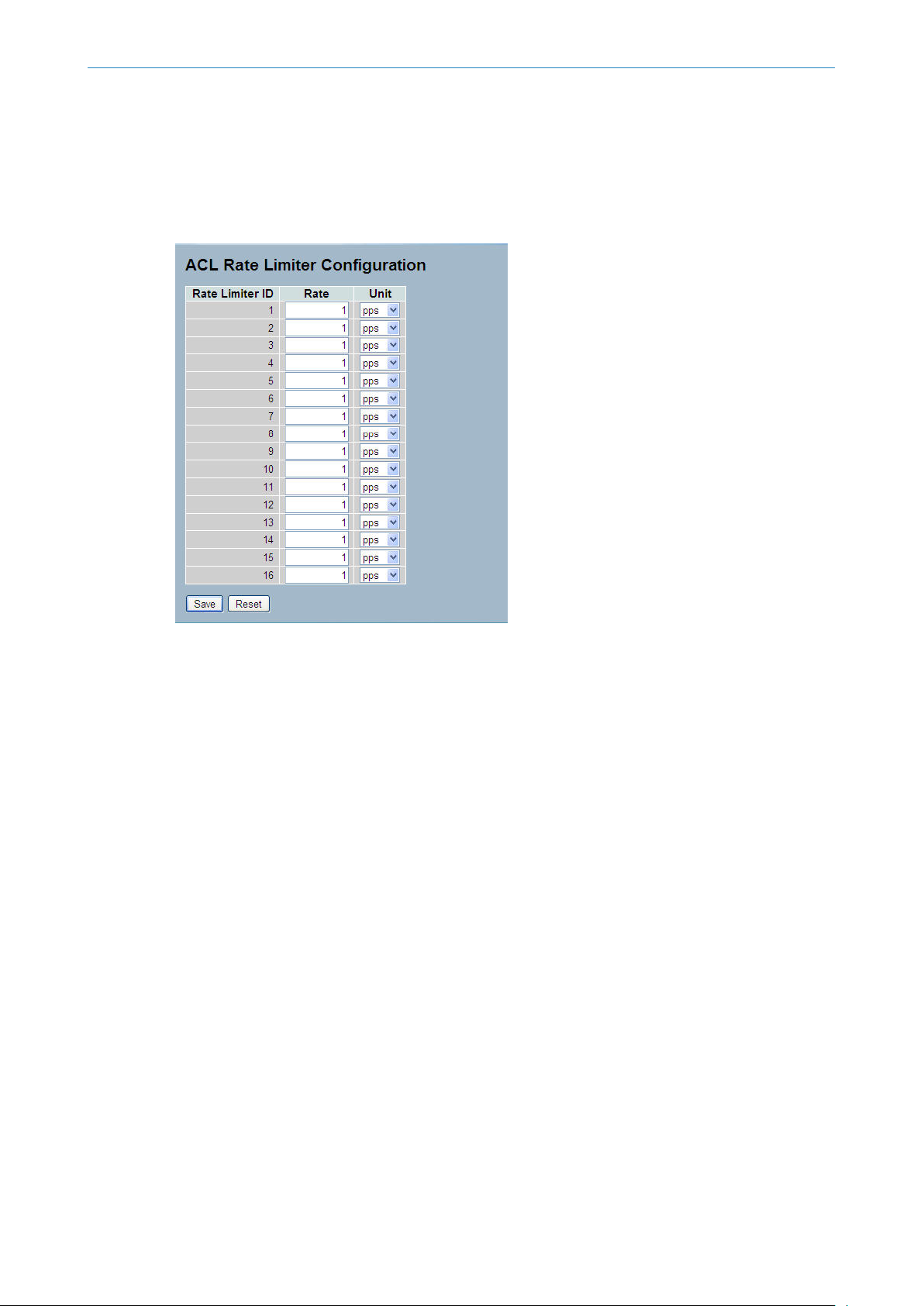
3.2.2 Rate Limiters
The section describes how to configure the switch’s ACL Rate Limiter parameters. The Rate Limiter Level from 1 to 16
allows the user to set rate limiter values and units (pps or kbps).
Web Interface
To configure ACL Rate Limiter in the web interface:
1. Click Configuration, ACL, then Rate Limiter
2. Specify the Rate field and the range from 0 to 3276700.
20
Page 21
LANCOM GS-2352
3 Configuration
3. Select the unit: pps or kbps.
4. Click save to save the settings.
5. If you want to cancel the setting then you need to click the reset button. It will revert to previously saved values.
Figure 3-2.2: The ACL Rate Limiter Configuration
Parameter description:
Rate Limiter ID:
The rate limiter ID for the settings contained in the same row.
Rate
The allowed values are: 0-3276700 in pps or 0, 100, 200, 300, ..., 1000000 in kbps.
Unit:
Specify the rate unit. The allowed values are:
pps: packets per second.
kbps: Kbits per second.
Buttons
Save – Click to save changes.
Reset – Click to undo any changes made locally and revert to previously saved values.
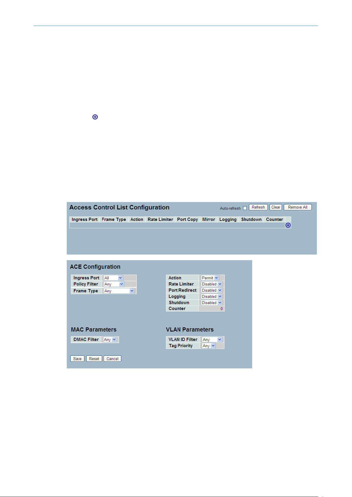
3.2.3 Access Control List
The section describes how to configure Access Control List rules. An Access Control List (ACL) is a sequential list of permit
or deny conditions that apply to IP addresses, MAC addresses, or other more specific criteria. This switch tests ingress
packets against the conditions in an ACL one by one. A packet will be accepted as soon as it matches a permit rule, or
dropped as soon as it matches a deny rule. If no rules match, the frame is accepted. Other actions can also be invoked
when a matching packet is found, including rate limiting, copying matching packets to another port or to the system
log, or shutting down a port.
21
Page 22
LANCOM GS-2352
3 Configuration
This page shows the Access Control List (ACL), which is made up of the ACEs defined on this switch. Each row describes
the ACE that is defined. The maximum number of ACEs is 256 on each switch. Click on the lowest plus sign to add a
new ACE to the list. The reserved ACEs are used for internal protocol and cannot be edited or deleted, the order sequence
cannot be changed and the priority is highest
Web Interface
To configure Access Control Lists in the web interface:
1. Click Configuration, ACL, then Configuration
2. Click the button to add a new ACL, or use the other ACL
modification buttons to specify the editing action (i.e., edit, delete, or moving the relative position of entry in the list)
3. Specify the parameters of the ACE
4. Click save to save the settings.
5. If you want to cancel the setting then you need to click the reset button. It will revert to previously saved values.
6. When editing an entry on the ACE Configuration page, note that the Items displayed depend on various selections,
such as Frame Type and IP Protocol Type. Specify the relevant criteria to be matched for this rule, and set the actions to
take when a rule is matched (such as Rate Limiter, Port Copy, Logging, and Shutdown).
Figure 3-2.3: The ACL Rate Limiter Configuration
22
Parameter description:
Ingress Port:
Indicates the ingress port of the ACE. Possible values are:
Any: The ACE will match any ingress port.
Policy: The ACE will match ingress ports with a specific policy.
Port: The ACE will match a specific ingress port.
Frame Type:
Page 23

LANCOM GS-2352
3 Configuration
Indicates the frame type of the ACE. Possible values are:
Any: The ACE will match any frame type.
Ethernet ype: The ACE will match Ethernet Type frames. Note that an Ethernet Type based ACE will not get matched by
IP and ARP frames.
ARP: The ACE will match ARP/RARP frames.
IPv4: The ACE will match all IPv4 frames.
Action:
Indicates the forwarding action of the ACE.
Permit: Frames matching the ACE may be forwarded and learned.
Deny: Frames matching the ACE are dropped.
Rate Limiter:
Indicates the rate limiter number of the ACE. The allowed range is 1 to 16. When Disabled is displayed, the rate limiter
operation is disabled.
Port Copy:
Indicates the port copy operation of the ACE. Frames matching the ACE are copied to the port number. The allowed
values are Disabled or a specific port number. When Disabled is displayed, the port copy operation is disabled.
Mirror:
Specify the mirror operation of this port. The allowed values are:
Enabled: Frames received on the port are mirrored.
Disabled: Frames received on the port are not mirrored.
The default value is "Disabled".
Logging:
Indicates the logging operation of the ACE. Possible values are:
Enabled: Frames matching the ACE are stored in the System Log.
Disabled: Frames matching the ACE are not logged.
Please note that the System Log memory size and logging rate is limited.
Shutdown:
Indicates the port shut down operation of the ACE. Possible values are:
Enabled: If a frame matches the ACE, the ingress port will be disabled.
Disabled: Port shut down is disabled for the ACE.
Counter:
The counter indicates the number of times the ACE was hit by a frame.
Modification Buttons
You can modify each ACE (Access Control Entry) in the table using the following buttons:
: Inserts a new ACE before the current row.
: Edits the ACE row.
: Moves the ACE up the list.
: Moves the ACE down the list.
: Deletes the ACE.
23
Page 24

LANCOM GS-2352
3 Configuration
MAC Parameter:
SMAC Filter
(Only displayed when the frame type is Ethernet Type or ARP.)
Specify the source MAC filter for this ACE.
Any: No SMAC filter is specified. (SMAC filter status is "don't-care".)
Specific: If you want to filter a specific source MAC address with this ACE, choose this value. A field for entering an SMAC
value appears.
SMAC Value
When "Specific" is selected for the SMAC filter, you can enter a specific source MAC address. The legal format is
"xx-xx-xx-xx-xx-xx" or "xx.xx.xx.xx.xx.xx" or "xxxxxxxxxxxx" (x is a hexadecimal digit). A frame that hits this ACE matches
this SMAC value.
DMAC Filter
Specify the destination MAC filter for this ACE.
Any: No DMAC filter is specified. (DMAC filter status is "don't-care".)
: The lowest plus sign adds a new entry at the bottom of the ACE listings.
MC: Frame must be multicast.
BC: Frame must be broadcast.
UC: Frame must be unicast.
Specific: If you want to filter a specific destination MAC address with this ACE, choose this value. A field for entering a
DMAC value appears.
DMAC Value
When "Specific" is selected for the DMAC filter, you can enter a specific destination MAC address. The legal format is
"xx-xx-xx-xx-xx-xx" or "xx.xx.xx.xx.xx.xx" or "xxxxxxxxxxxx" (x is a hexadecimal digit). A frame that hits this ACE matches
this DMAC value.
Buttons
Save – Click to save changes.
Reset – Click to undo any changes made locally and revert to previously saved values.
Auto-refresh:
Activate the auto-refresh to refresh the information automatically.
Refresh
Refresh the ACL configuration manually
Clear
Clear the ACL configuration.
Remove All
Remove all ACL configurations from the table.
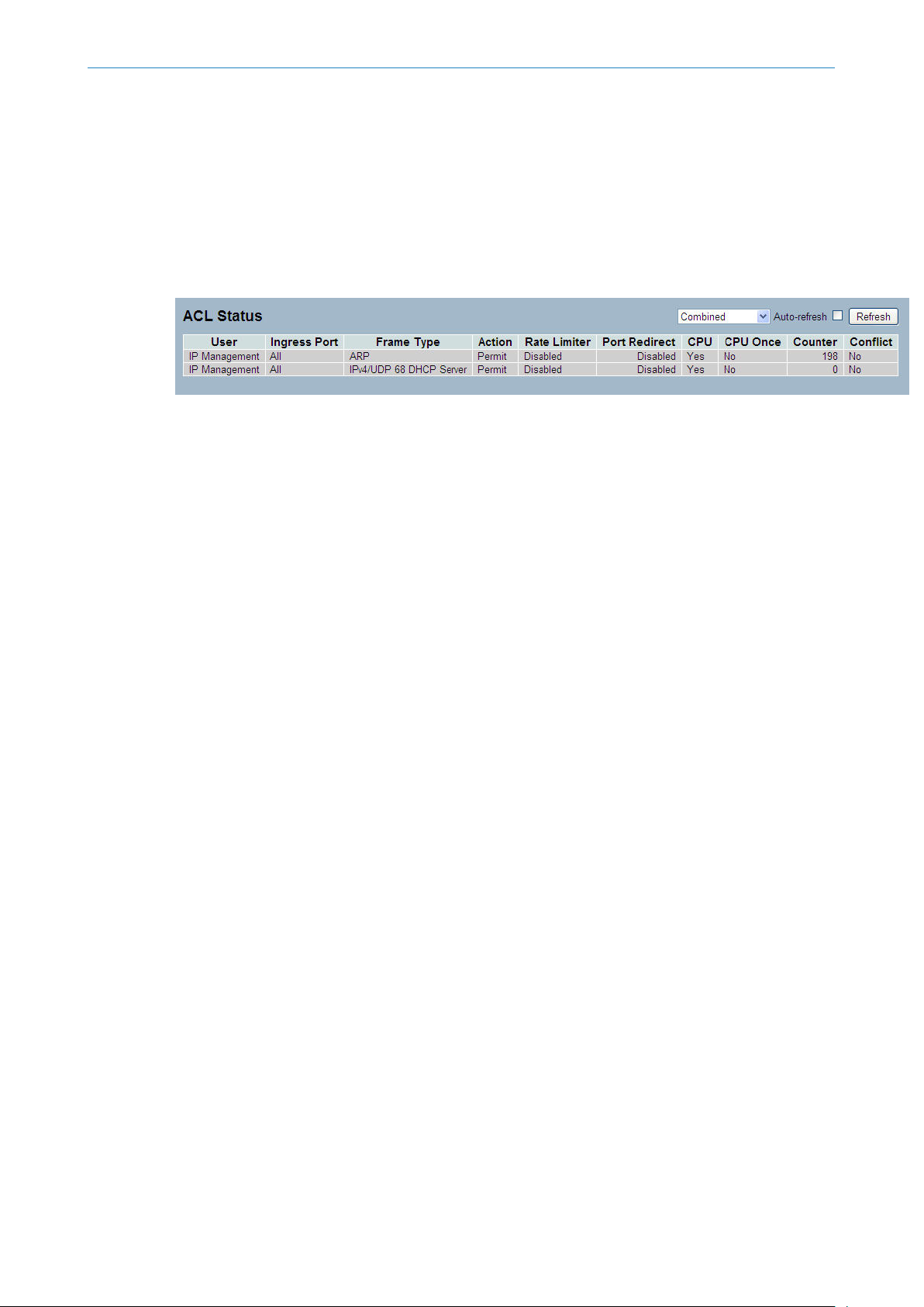
3.2.4 ACL Status
The section describes how to shows the ACL status by different ACL users. Each row describes the ACE that is defined.
It is a conflict if a specific ACE is not applied to the hardware due to hardware limitations. The maximum number of
ACEs is 256 on each switch.
24
Page 25
Web Interface
To display the ACL status in the web interface:
1. Click Configuration, ACL, then ACL status
2. If you want to auto-refresh the information then you need to activate “Auto-refresh”.
3. Click “Refresh“ to refresh the ACL Status
Figure 3-2.4: The ACL Status
Parameter description:
User:
Indicates the ACL user.
Ingress Port:
LANCOM GS-2352
3 Configuration
Indicates the ingress port of the ACE. Possible values are:
Any: The ACE will match any ingress port.
Policy: The ACE will match ingress ports with a specific policy.
Port: The ACE will match a specific ingress port.
Frame Type:
Indicates the frame type of the ACE. Possible values are:
Any: The ACE will match any frame type.
EType: The ACE will match Ethernet Type frames. Note that an Ethernet Type based ACE will not get matched by IP and
ARP frames.
ARP: The ACE will match ARP/RARP frames.
IPv4: The ACE will match all IPv4 frames.
Action:
Indicates the forwarding action of the ACE.
Permit: Frames matching the ACE may be forwarded and learned.
Deny: Frames matching the ACE are dropped.
Rate Limiter:
Indicates the rate limiter number of the ACE. The allowed range is 1 to 16. When Disabled is displayed, the rate limiter
operation is disabled.
Port Copy:
Indicates the port copy operation of the ACE. Frames matching the ACE are copied to the port number. The allowed
values are Disabled or a specific port number. When Disabled is displayed, the port copy operation is disabled.
Mirror:
Specify the mirror operation of this port. The allowed values are:
Enabled: Frames received on the port are mirrored.
Disabled: Frames received on the port are not mirrored.
25
Page 26

LANCOM GS-2352
3 Configuration
The default value is "Disabled".
CPU:
Forward packet that matched the specific ACE to CPU.
CPU Once:
Forward first packet that matched the specific ACE to CPU.
Counter:
The counter indicates the number of times the ACE was hit by a frame.
Conflict:
Indicates the hardware status of the specific ACE. The specific ACE is not applied to the hardware due to hardware
limitations.
Auto-refresh:
Activate the auto-refresh to refresh the information automatically.
Refresh
Refresh the ACL status information manually.
3.3 Aggregation
You can bundle more than one port with the same speed, full duplex and the same MAC to be a single logical port, thus
the logical port aggregates the bandwidth of these ports. This means you can apply your current Ethernet equipment’s
to build the bandwidth aggregation. For example, if there are three Fast Ethernet ports aggregated in a logical port,
then this logical port has bandwidth three times as high as a single Fast Ethernet port has.
3.3.1 Static Trunk
The Aggregation Configuration is used to configure the settings of Link Aggregation. You can bundle more than one
port with the same speed, full duplex and the same MAC to be a single logical port, thus the logical port aggregates the
bandwidth of these ports. This means you can apply your current Ethernet equipment’s to build the bandwidth aggregation.
3-3.1.1 Static Trunk
Ports using Static Trunk as their trunk method can choose their unique Static GroupID to form a logic “trunked port”.
The benefit of using Static Trunk method is that a port can immediately become a member of a trunk group without any
handshaking with its peer port. This is also a disadvantage because the peer ports of your static trunk group may not
know that they should be aggregate together to form a “logic trunked port”. Using Static Trunk on both end of a link is
strongly recommended. Please also note that low speed links will stay in “not ready” state when using static trunk to
aggregate with high speed links.
Web Interface
To configure the Trunk Aggregation Hash mode and Aggregation Group in the web interface:
1. Click Configuration, Static Trunk, and then Aggregation Mode Configuration.
26
2. Activate to enable or disable the aggregation mode function.
Activate Aggregation Group ID and Port members
3. Click Save to save the setting
4. If you want to cancel the setting then you need to click the reset button. It will revert to previously saved values.
Figure 3-3.1.1: The Aggregation Mode Configuration
Page 27

LANCOM GS-2352
3 Configuration
Parameter description:
Hash Code Contributors
Source MAC Address:
The Source MAC address can be used to calculate the destination port for the frame. Check to enable the use of the
Source MAC address, or uncheck to disable. By default, Source MAC Address is enabled.
Destination MAC Address:
The Destination MAC Address can be used to calculate the destination port for the frame. Check to enable the use of
the Destination MAC Address, or uncheck to disable. By default, Destination MAC Address is disabled.
IP Address:
The IP address can be used to calculate the destination port for the frame. Check to enable the use of the IP Address,
or uncheck to disable. By default, IP Address is enabled.
TCP/UDP Port Number:
The TCP/UDP port number can be used to calculate the destination port for the frame. Check to enable the use of the
TCP/UDP Port Number, or uncheck to disable. By default, TCP/UDP Port Number is enabled.
Aggregation Group Configuration
Locality:
Indicates the aggregation group type. This field is only valid for switches.
Global: The group members may reside on different units. The device supports two 8-port global aggregations.
Local: The group members reside on the same unit. Each local aggregation may consist of up to 16 members.
Group ID:
Indicates the group ID for the settings contained in the same row. Group ID "Normal" indicates there is no aggregation.
Only one group ID is valid per port.
Port Members:
Each switch port is listed for each group ID. Select a radio button to include a port in an aggregation, or clear the radio
button to remove the port from the aggregation. By default, no ports belong to any aggregation group. Only full duplex
ports can join an aggregation and ports must be in the same speed in each group.
Buttons
Save – Click to save changes.
Reset – Click to undo any changes made locally and revert to previously saved values.
27
Page 28
LANCOM GS-2352
3 Configuration
3.3.2 LACP
Ports using Link Aggregation Control Protocol (according to IEEE 802.3ad specification) as their trunking method can
choose their unique LACP GroupID to form a logic “trunked port”. The benefit of using LACP is that a port makes an
agreement with its peer port before it becomes a ready member of a “trunk group” (also called aggregator). LACP is
safer than the other trunking method - static trunk.
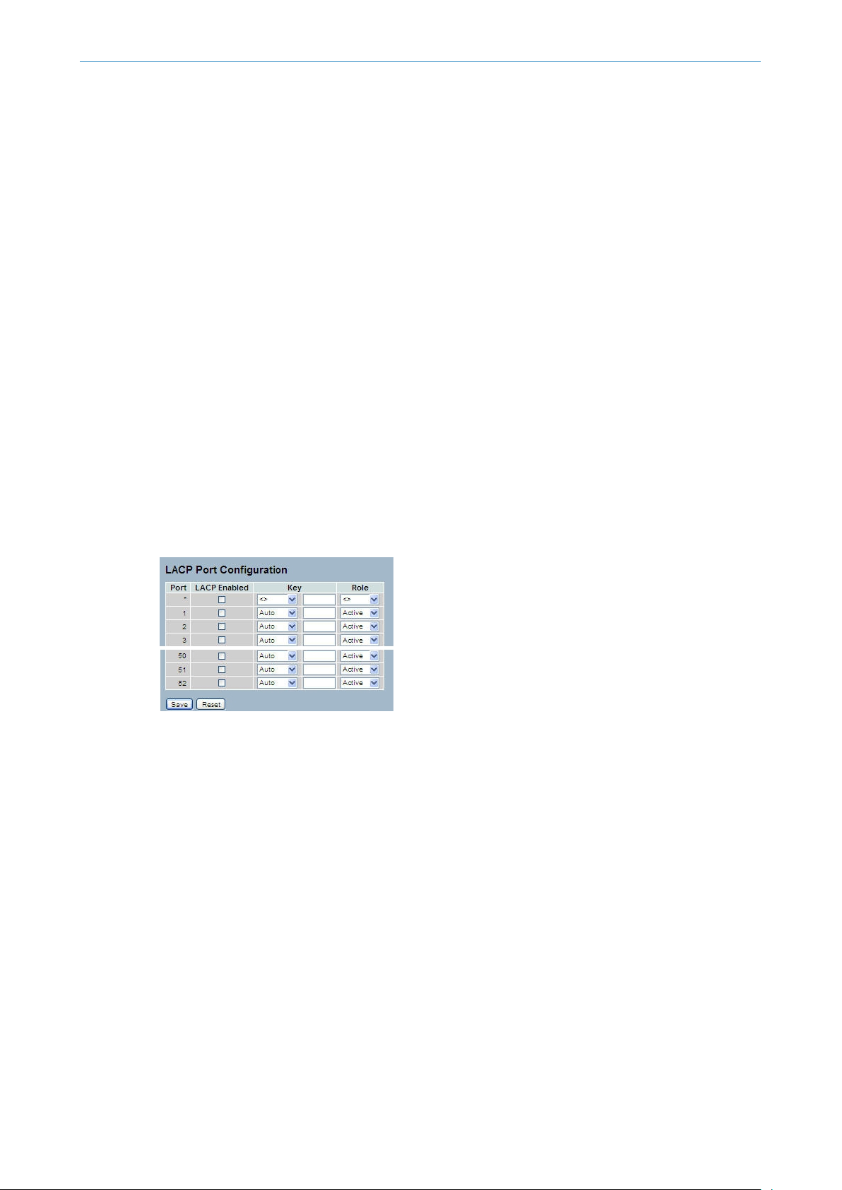
3-3.2.1 Configuration
This page allows the user to inspect the current LACP port configurations, and possibly change them as well An LACP
trunk group with more than one ready member-ports is a “real trunked” group. An LACP trunk group with only one or
less than one ready member-ports is not a “real trunked” group.
Web Interface
To configure the Trunk Aggregation LACP parameters in the web interface:
1. Click Configuration, LACP, Configuration
2. Activate to enable or disable the LACP on the port.
3. Select the Key parameter: Auto or specific value. Default is Auto.
4. Select the Role: Active or Passive. Default is Active.
5. Click Save to save the settings
6. If you want to cancel the setting then you need to click the reset button. It will revert to previously saved values.
Figure 3-3.2.1: The LACP Port Configuration
Parameter description:
Port:
The switch port number.
LACP Enabled:
Controls whether LACP is enabled on this switch port. LACP will form an aggregation when 2 or more ports are connected
to the same partner. LACP can form max 12 LLAGs per switch and 2 GLAGs.
Key:
28
The Key value incurred by the port, range 1-65535 . The Auto setting will set the key as appropriate by the physical link
speed, 10Mb = 1, 100Mb = 2, 1Gb = 3. Using the Specific setting, a user-defined value can be entered. Ports with the
same Key value can participate in the same aggregation group, while ports with different keys cannot.
Role:
The Role shows the LACP activity status. The Active will transmit LACP packets each second, while Passive will wait for
a LACP packet from a partner (speak if spoken to).
Buttons
Save – Click to save changes.
Page 29
LANCOM GS-2352
Reset – Click to undo any changes made locally and revert to previously saved values.
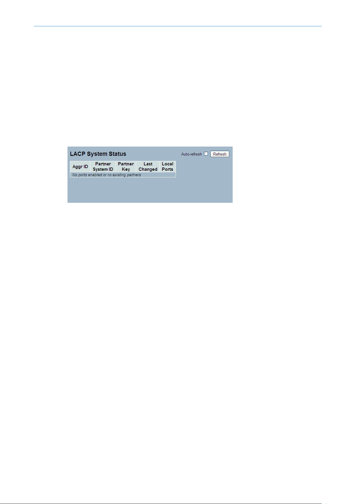
3-3.2.2 System Status
This section describes the LACP System Status which is provided when LACP is configured on the switch.
Web Interface
To display the LACP System status in the web interface:
1. Click Configuration, LACP, System Status
2. If you want to auto-refresh the information then you need to activate “Auto-refresh”.
3. Click “Refresh“ to refresh the LACP System Status.
Figure 3-3.2.2: The LACP System Status
3 Configuration
Parameter description:
Aggr ID:
The Aggregation ID associated with this aggregation instance. For LLAG the id is shown as 'isid:aggr-id' and for GLAGs
as 'aggr-id'
Partner System ID:
The system ID (MAC address) of the aggregation partner.
Partner Key:
The Key that the partner has assigned to this aggregation ID.
Last changed:
The time since this aggregation changed.
Local Ports:
Shows which ports are a part of this aggregation for this switch. The format is: "Switch ID:Port".
Auto-refresh:
To activate the auto-refresh to refresh the information automatically.
Refresh
Refresh the LACP System status information manually.
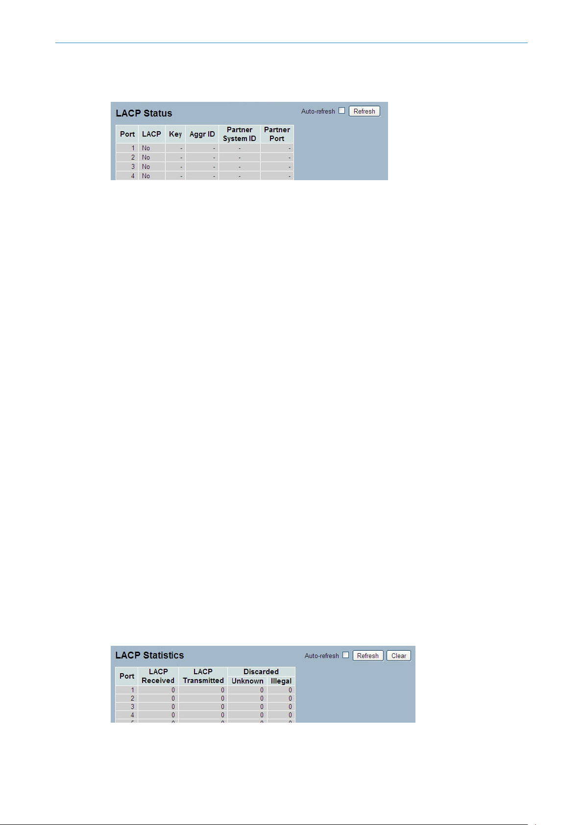
3-3.2.3 Port Status
This section describes the LACP Status which is provided when LACP is configured on the switch.
Web Interface
To display the LACP Port status in the web interface:
1. Click Configuration, LACP, Port Status
2. If you want to auto-refresh the information then you need to activate “Auto-refresh”.
3. Click “Refresh“ to refresh the LACP Port Status.
29
Page 30
LANCOM GS-2352
3 Configuration
Figure 3-3.2.3: The LACP Status
Parameter description:
Port:
The switch port number.
LACP:
'Yes' means that LACP is enabled and the port link is up. 'No' means that LACP is not enabled or that the port link is
down. 'Backup' means that the port could not join the aggregation group but will join if other port leaves. Meanwhile
its LACP status is disabled.
Key:
The key assigned to this port. Only ports with the same key can aggregate together.
Aggr ID:
The Aggregation ID assigned to this aggregation group. IDs 1 and 2 are GLAGs while IDs 3-14 are LLAGs.
Partner System ID:
The partner's System ID (MAC address).
Partner Port:
The partner's port number connected to this port.
Auto-refresh:
To activate the auto-refresh to refresh the information automatically.
Refresh:
Refresh the LACP port status information manually.
3-3.2.4 Port Statistics
This section describes the LACP Statistics which are provided when LACP is configured on the switch.
Web Interface
To display the LACP Port statistics in the web interface:
1. Click Configuration, LACP, Port Statistics
2. If you want to auto-refresh the information then you need to activate “Auto refresh”.
30
3. Click “Refresh“ to refresh the LACP Statistics.
Figure 3-3.2.4: The LACP Statistics
Page 31

Parameter description:
Port:
The switch port number.
LACP Received:
Shows how many LACP frames have been received at each port.
LACP Transmitted:
Shows how many LACP frames have been sent from each port.
Discarded:
Shows how many unknown or illegal LACP frames have been discarded at each port.
Auto-refresh:
To activate the auto-refresh to refresh the information automatically.
Refresh:
Refresh the LACP port statistics information manually.
Clear:
LANCOM GS-2352
3 Configuration
Clear the LACP port statistics information manually.
3.4 Spanning Tree
The Spanning Tree Protocol (STP) can be used to detect and disable network loops, and to provide backup links between
switches, bridges or routers. This allows the switch to interact with other bridging devices (that is, an STP-compliant
switch, bridge or router) in your network to ensure that only one route exists between any two stations on the network,
and provide backup links which automatically take over when a primary link goes down.
STP - STP uses a distributed algorithm to select a bridging device (STP- compliant switch, bridge or router) that serves
as the root of the spanning tree network. It selects a root port on each bridging device (except for the root device) which
incurs the lowest path cost when forwarding a packet from that device to the root device. Then it selects a designated
bridging device from each LAN which incurs the lowest path cost when forwarding a packet from that LAN to the root
device. All ports connected to designated bridging devices are assigned as designated ports. After determining the lowest
cost spanning tree, it enables all root ports and designated ports, and disables all other ports. Network packets are
therefore only forwarded between root ports and designated ports, eliminating any possible network loops.
Once a stable network topology has been established, all bridges listen for Hello BPDUs (Bridge Protocol Data Units)
transmitted from the Root Bridge. If a bridge does not get a Hello BPDU after a predefined interval (Maximum Age), the
bridge assumes that the link to the Root Bridge is down. This bridge will then initiate negotiations with other bridges
to reconfigure the network to reestablish a valid network topology.
3.4.1 Bridge Settings
The section describes how to configure the Spanning Tree Bridge and STP System settings. It allows you to configure
STP System settings which are used by all STP Bridge instances in the Switch.
31
Page 32

LANCOM GS-2352
3 Configuration
Web Interface
To configure the Spanning Tree Bridge Settings parameters in the web interface:
1. Click Configuration, Spanning Tree, Bridge Settings
2. Select the parameters and enter available values of parameters in the blank field in Basic Settings
3. Activate to enable or disable the parameters and enter available value of parameters in the blank field in Advanced
settings
4. Click Save to save the setting
5 .If you want to cancel the setting then you need to click the Reset button. It will revert to previously saved values
Figure 3-4.1: The STP Bridge Configuration
Parameter description:
Basic Settings
Protocol Version:
The STP protocol version setting. Valid values are STP, RSTP and MSTP.
Bridge Priority:
Controls the bridge priority. Lower numeric values have better priority. The bridge priority plus the MSTI instance number,
concatenated with the 6-byte MAC address of the switch forms a Bridge Identifier. For MSTP operation, this is the priority
of the CIST. Otherwise, this is the priority of the STP/RSTP bridge.
Forward Delay:
The delay used by STP Bridges to transit Root and Designated Ports to Forwarding (used in STP compatible mode). Valid
values are in the range 4 to 30 seconds.
Max Age:
The maximum age of the information transmitted by the Bridge when it is the Root Bridge. Valid values are in the range
6 to 40 seconds, and MaxAge must be <= (FwdDelay-1)*2.
Maximum Hop Count:
This defines the initial value of remaining Hops for MSTI information generated at the boundary of an MSTI region. It
defines how many bridges a root bridge can distribute its BPDU information to. Valid values are in the range 6 to 40
hops.
Transmit Hold Count:
32
Page 33

LANCOM GS-2352
3 Configuration
The number of BPDU's a bridge port can send per second. When exceeded, transmission of the next BPDU will be delayed.
Valid values are in the range 1 to 10 BPDU's per second.
Advanced Settings
Edge Port BPDU Filtering:
Control whether a port explicitly configured as Edge will transmit and receive BPDUs.
Edge Port BPDU Guard:
Control whether a port explicitly configured as Edge will disable itself upon reception of a BPDU. The port will enter the
error-disabled state, and will be removed from the active topology.
Port Error Recovery:
Control whether a port in the error-disabled state automatically will be enabled after a certain time. If recovery is not
enabled, ports have to be disabled and re-enabled for normal STP operation. The condition is also cleared by a system
reboot.
Port Error Recovery Timeout:
The time to pass before a port in the error-disabled state can be enabled. Valid values are between 30 and 86400 seconds
(24 hours).
Buttons
Save – Click to save changes.
Reset – Click to undo any changes made locally and revert to previously saved values.
3.4.2 MSTI Mapping
When you implement a Spanning Tree protocol on the switch that the bridge instance the CIST is not available for explicit
mapping, as it will receive the VLANs not explicitly mapped. Due to the reason that you need to set the list of VLANs
mapped to the MSTI. The VLANs must be separated with comma and/or space. A VLAN can only be mapped to one MSTI.
An unused MSTI should just be left empty. (I.e. not having any VLANs mapped to it.)
This section describes how the user can inspect the current STP MSTI bridge instance priority configurations, and possibly
change them as well.
Web Interface
To configure the Spanning Tree MSTI Mapping parameters in the web interface:
1. Click Configuration, Spanning Tree, MSTI Mapping
2. Specify the configuration identification parameters in the field
3. Specify the VLANs Mapped blank field.
4. Click Save to save the setting
5. If you want to cancel the setting then you need to click the Reset button. It will revert to previously saved values
Figure 3-4.2: The MSTI Configuration
33
Page 34

LANCOM GS-2352
3 Configuration
Parameter description:
Configuration Identification
Configuration Name:
The name identifying the VLAN to MSTI mapping. Bridges must share the name and revision (see below), as well as the
VLAN-to-MSTI mapping configuration in order to share spanning trees for MSTI's (Intra-region). The name is at most 32
characters.
Configuration Revision:
The revision of the MSTI configuration named above. This must be an integer between 0 and 65535.
MSTI Mapping
MSTI:
The bridge instance. The CIST is not available for explicit mapping, as it will receive the VLANs not explicitly mapped.
VLANs Mapped:
The list of VLANs mapped to the MSTI. The VLANs must be separated with comma and/or space. A VLAN can only be
mapped to one MSTI. An unused MSTI should just be left empty. (I.e. not having any VLANs
Buttons
Save – Click to save changes.
Reset – Click to undo any changes made locally and revert to previously saved values.
3.4.3 MSTI Priorities
When you implement a Spanning Tree protocol on the switch that the bridge instance. The CIST is the default instance
which is always active. For controls the bridge priority. Lower numeric values have better priority. The bridge priority
plus the MSTI instance number, concatenated with the 6-byte MAC address of the switch forms a Bridge Identifier
34
Page 35

LANCOM GS-2352
3 Configuration
This section show how the user can inspect the current STP MSTI bridge instance priority configurations, and possibly
change them as well.
Web Interface
To configure the Spanning Tree MSTI Priorities parameters in the web interface:
1. Click Configuration, Spanning Tree, MSTI Priorities
2. Scroll the Priority maximum is 240. Default is 128.
3. Click "Save" to save the settings.
4. If you want to cancel the setting then you need to click the Reset button. It will revert to previously saved values
Figure 3-4.3: The MSTI Configuration
Parameter description:
MSTI:
The bridge instance. The CIST is the default instance, which is always active.
Priority:
Controls the bridge priority. Lower numeric values have better priority. The bridge priority plus the MSTI instance number,
concatenated with the 6-byte MAC address of the switch forms a Bridge Identifier.
Buttons
Save – Click to save changes.
Reset – Click to undo any changes made locally and revert to previously saved values.
3.4.4 CIST Ports
When you implement a Spanning Tree protocol on the switch that the bridge instance. You need to configure the CIST
Ports. The section describes how the user to inspect to inspect the current STP CIST port configurations, and possibly
change them as well.
Web Interface
To configure the Spanning Tree CIST Ports parameters in the web interface:
1. Click Configuration, Spanning Tree, CIST Ports
2. Set the parameters of the CIST Aggregated Port Configuration.
3. Enable or disable the STP, then set the parameters of the CIST normal Port configuration.
35
Page 36

LANCOM GS-2352
3 Configuration
4. Click Save to save the settings.
5. If you want to cancel the settings then you need to click the Reset button. It will revert to previously saved values.
Figure 3-4.4: The STP CIST Port Configuration
Parameter description:
Port:
The switch port number of the logical STP port.
STP Enabled:
Controls whether STP is enabled on this switch port.
Path Cost:
Controls the path cost incurred by the port. The Auto setting will set the path cost as appropriate by the physical link
speed, using the 802.1D recommended values. Using the Specific setting, a user-defined value can be entered. The path
cost is used when establishing the active topology of the network. Lower path cost ports are chosen as forwarding ports
in favor of higher path cost ports. Valid values are in the range 1 to 200000000.
Priority:
Controls the port priority. This can be used to control priority of ports having identical port cost. (See above).
operEdge (state flag):
Operational flag describing whether the port is connecting directly to edge devices. (No Bridges attached). Transition to
the forwarding state is faster for edge ports (having operEdge true) than for other ports. The value of this flag is based
on AdminEdge and AutoEdge fields. This flag is displayed as Edge in Monitor->Spanning Tree -> STP Detailed Bridge
Status.
AdminEdge:
Controls whether the operEdge flag should start as set or cleared. (The initial operEdge state when a port is initialized).
36
AutoEdge:
Controls whether the bridge should enable automatic edge detection on the bridge port. This allows operEdge to be
derived from whether BPDU's are received on the port or not.
Restricted Role:
Page 37

LANCOM GS-2352
3 Configuration
If enabled, causes the port not to be selected as Root Port for the CIST or any MSTI, even if it has the best spanning tree
priority vector. Such a port will be selected as an Alternate Port after the Root Port has been selected. If set, it can cause
lack of spanning tree connectivity. It can be set by a network administrator to prevent bridges external to a core region
of the network influence the spanning tree active topology, possibly because those bridges are not under the full control
of the administrator. This feature is also known as Root Guard.
Restricted TCN:
If enabled, causes the port not to propagate received topology change notifications and topology changes to other ports.
If set it can cause temporary loss of connectivity after changes in a spanning tree's active topology as a result of persistently
incorrect learned station location information. It is set by a network administrator to prevent bridges external to a core
region of the network, causing address flushing in that region, possibly because those bridges are not under the full
control of the administrator or the physical link state of the attached LANs transits frequently.
BPDU Guard:
If enabled, causes the port to disable itself upon receiving valid BPDU's. Contrary to the similar bridge setting, the port
Edge status does not affect this setting. A port entering error-disabled state due to this setting is subject to the bridge
Port Error Recovery setting as well.
Point to Point
Controls whether the port connects to a point-to-point LAN rather than to a shared medium. This can be automatically
determined, or forced either true or false. Transition to the forwarding state is faster for point-to-point LANs than for
shared media.
Buttons
Save – Click to save changes.
Reset – Click to undo any changes made locally and revert to previously saved values.
3.4.5 MSTI Ports
The section describes how to view and change the current STP MSTI port configurations.
An MSTI port is a virtual port, which is instantiated separately for each active CIST (physical) port for each MSTI instance
configured on and applicable to the port. The MSTI instance must be selected before displaying actual MSTI port
configuration options. It contains MSTI port settings for physical and aggregated ports.
Web Interface
To configure the Spanning Tree MSTI Port Configuration parameters in the web interface:
1. Click Configuration, Spanning Tree, MSTI Ports
2. Select the MST1 or other MSTI Port
3. Click Get to set the detail parameters of the MSTI Ports.
4. Set all parameters of the MSTI Port configuration.
5. Click Save to save the setting
6. If you want to cancel the setting then you need to click the Reset button. It will revert to previously saved values
Figure 3-4.5: The MSTI Port Configuration
37
Page 38

LANCOM GS-2352
3 Configuration
Parameter description:
Port:
The switch port number of the corresponding STP CIST (and MSTI) port.
Path Cost:
Controls the path cost incurred by the port. The Auto setting will set the path cost as appropriate by the physical link
speed, using the 802.1D recommended values. Using the Specific setting, a user-defined value can be entered. The path
cost is used when establishing the active topology of the network. Lower path cost ports are chosen as forwarding ports
in favor of higher path cost ports. Valid values are in the range 1 to 200000000.
Priority:
Controls the port priority. This can be used to control priority of ports having identical port cost. (See above).
Buttons
Save – Click to save changes.
Reset – Click to undo any changes made locally and revert to previously saved values.
3.4.6 Bridge Status
After you complete the MSTI Port configuration the you could to ask the switch display the Bridge Status. The section
provides a status overview of all STP bridge instances. The displayed table contains a row for each STP bridge instance,
where the column displays the following information:
Web Interface
To display the STP Bridges status in the web interface:
1. Click Configuration, Spanning Tree, STP Bridges
2. If you want to auto-refresh the information then you need to activate “Auto-refresh”.
3. Click “Refresh“ to refresh the STP Bridges.
Figure 3-4.6: The STP Bridges status
38
Parameter description:
MSTI:
The Bridge Instance. This is also a link to the STP Detailed Bridge Status.
Page 39

LANCOM GS-2352
3 Configuration
Bridge ID:
The Bridge ID of this Bridge instance.
Root ID:
The Bridge ID of the currently elected root bridge.
Root Port:
The switch port currently assigned the root port role.
Root Cost:
Root Path Cost. For the Root Bridge it is zero. For all other Bridges, it is the sum of the Port Path Costs on the least cost
path to the Root Bridge.
Topology Flag:
The current state of the Topology Change Flag of this Bridge instance.
Topology Change Last:
The time since last Topology Change occurred.
Auto-refresh:
Activate the auto-refresh to refresh the information automatically.
Refresh:
Refresh the STP Bridges status information manually.
3.4.7 Port Status
After you complete the STP configuration you could ask the switch to display the STP Port Status. It displays the STP CIST
port status for physical ports of the currently selected switch.
Web Interface
To display the STP Port status in the web interface:
1. Click Configuration, Spanning Tree, STP Port Status
2. If you want to auto-refresh the information then you need to activate “Auto-refresh”.
3. Click “Refresh“ to refresh the STP Bridges.
Figure 3-4.7: The STP Port status
Parameter description:
Port:
The switch port number of the logical STP port.
CIST Role:
The current STP port role of the CIST port. The port role can be one of the following values: AlternatePort, Backup Port,
RootPort, DesignatedPort Disabled.
CIST State:
39
Page 40

LANCOM GS-2352
3 Configuration
The current STP port state of the CIST port. The port state can be one of the following values: Blocking Learning Forwarding.
Uptime
The time since the bridge port was last initialized.
Auto-refresh:
Activate the auto-refresh to refresh the information automatically.
Refresh
Refresh the STP Port status information manually.
3.4.8 Port Statistics
After you complete the STP configuration then you could to let the switch display the STP Statistics. The Section provides
you to ask switch to display the STP Statistics detail counters of bridge ports in the currently selected switch.
Web Interface
To display the STP Port status in the web interface:
1. Click Configuration, Spanning Tree, Port Statistics
2. If you want to auto-refresh the information then you need to activate “Auto-refresh”.
3. Click “Refresh“ to refresh the STP Bridges.
Figure 3-4.8: The STP Statistics
Parameter description:
Port:
The switch port number of the logical STP port.
MSTP:
The number of MSTP Configuration BPDU's received/transmitted on the port.
RSTP:
The number of RSTP Configuration BPDU's received/transmitted on the port.
40
STP:
The number of legacy STP Configuration BPDU's received/transmitted on the port.
TCN:
The number of (legacy) Topology Change Notification BPDU's received/transmitted on the port.
Discarded Unknown:
The number of unknown Spanning Tree BPDU's received (and discarded) on the port.
Discarded Illegal:
Page 41

The number of illegal Spanning Tree BPDU's received (and discarded) on the port.
Auto-refresh:
Activate the auto-refresh to refresh the information automatically.
Refresh
Refresh the STP Statistics information manually.
Clear
Clear the STP Statistics information manually.
3.5 IGMP Snooping
IGMP Snooping is used to establish the multicast groups to forward the multicast packet to the member ports, and, in
nature, avoids wasting the bandwidth while IP multicast packets are running over the network. This is because a switch
that does not support IGMP or IGMP Snooping can not tell the multicast packet from the broadcast packet, so it can
only treat them all as the broadcast packet. Without IGMP Snooping, the multicast packet forwarding function is plain
and nothing is different from broadcast packet.
LANCOM GS-2352
3 Configuration
A switch which supports IGMP Snooping with the functions of query, report and leave, a type of packet exchanged
between IP Multicast Router/Switch and IP Multicast Host, can update the information of the Multicast table when a
member (port) joins or leaves an IP Multicast Destination Address. With this function, once a switch receives an IP
multicast packet, it will forward the packet to the members who joined in a specified IP multicast group before.
The packets will be discarded by the IGMP Snooping if the user transmits multicast packets to the multicast group that
had not been built up in advance. IGMP mode enables the switch to issue IGMP function that you enable IGMP proxy
or snooping on the switch, which connects to a router closer to the root of the tree. This interface is the upstream
interface. The router on the upstream interface should be running IGMP.
3.5.1 Basic Configuration
The section describes how to set the basic IGMP snooping on the switch, which connects to a router closer to the root
of the tree. This interface is the upstream interface. The router on the upstream interface should be running IGMP.
Web Interface
To configure the IGMP Snooping parameters in the web interface:
1. Click Configuration, IGMP Snooping, Basic Configuration
2. Activate to select enable or disable which Global configuration
3. Activate which port wants to become a Router Port or enable/ disable the Fast Leave function.
4. Set the Throttling parameter.
5. Click Save to save the setting
6. If you want to cancel the setting then you need to click the Reset button. It will revert to previously saved values.
Figure 3-5.1: The IGMP Snooping Configuration.
41
Page 42

LANCOM GS-2352
3 Configuration
Parameter description:
Snooping Enabled:
Enable the Global IGMP Snooping.
Unregistered IPMCv4 Flooding enabled:
Enable unregistered IPMCv4 traffic flooding.
IGMP SSM Range:
SSM (Source-Specific Multicast) Range allows the SSM-aware hosts and routers run the SSM service model for the groups
in the address range. Format: (IP address/ sub mask)
Proxy Enabled:
Enable IGMP Proxy. This feature can be used to avoid forwarding unnecessary join and leave messages to the router
side.
Port:
It shows the physical Port index of switch.
Router Port:
Specify which ports act as router ports. A router port is a port on the Ethernet switch that leads towards the Layer 3
multicast device or IGMP querier.
If an aggregation member port is selected as a router port, the whole aggregation will act as a router port.
Fast Leave:
Enable the fast leave on the port.
42
Throttling:
Enable to limit the number of multicast groups to which a switch port can belong.
Buttons
Save – Click to save changes.
Reset – Click to undo any changes made locally and revert to previously saved values.
Page 43

3.5.2 VLAN Configuration
The section describes the VLAN configuration setting process integrated with IGMP Snooping function. For each setting
page shows up to 99 entries from the VLAN table, default being 20, selected through the "entries per page" input field.
When first visited, the web page will show the first 20 entries from the beginning of the VLAN Table. The first displayed
will be the one with the lowest VLAN ID found in the VLAN Table. The "VLAN" input fields allow the user to select the
starting point in the VLAN Table. Clicking the button will update the displayed table starting from that or the next closest
VLAN Table match.
Web Interface
To configure the IGMP Snooping VLAN in the web interface:
1. Click Configuration, IGMP Snooping, VLAN Configuration
2. Activate to select enable or disable Snooping, IGMP Querier
3. Specify the parameters in the blank field.
4. Click the refresh to update the data or click << or >> to display previous entry or next entry.
5. Click Save to save the setting
LANCOM GS-2352
3 Configuration
6. If you want to cancel the setting then you need to click the Reset button. It will revert to previously saved values
Figure 3-5.2: The IGMP Snooping VLAN Configuration.
Parameter description:
VLAN ID:
It displays the VLAN ID of the entry.
Snooping Enabled:
Enable the per-VLAN IGMP Snooping. Only up to 32 VLANs can be selected. .
IGMP Querier:
A router sends IGMP Query messages onto a particular link. This Router is called the Querier. Enable the IGMP Querier
in the VLAN.
Compatibility:
Compatibility is maintained by hosts and routers taking appropriate actions depending on the versions of IGMP operating
on hosts and routers within a network. The allowed selection is IGMP-Auto, Forced IGMPv1, Forced IGMPv2, Forced
IGMPv3, default compatibility value is IGMP-Auto.
Rv:
Robustness Variable. The Robustness Variable allows tuning for the expected packet loss on a network. The allowed
range is 1 to 255; default robustness variable value is 2.
QI:
Query Interval. The Query Interval is the interval between General Queries sent by the Querier. The allowed range is 1
to 31744 seconds; default query interval is 125 seconds.
43
Page 44

LANCOM GS-2352
3 Configuration
QRI:
Query Response Interval. The Max Response Time used to calculate the Max Resp Code inserted into the periodic General
Queries. The allowed range is 0 to 31744 in tenths of seconds; default query response interval is 100 in tenths of seconds
(10 seconds).
LLQI (LMQI for IGMP):
Last Member Query Interval. The Last Member Query Time is the time value represented by the Last Member Query
Interval, multiplied by the Last Member Query Count. The allowed range is 0 to 31744 in tenths of seconds; default last
member query interval is 10 in tenths of seconds (1 second).
URI:
Unsolicited Report Interval. The Unsolicited Report Interval is the time between repetitions of a host's initial report of
membership in a group. The allowed range is 0 to 31744 seconds, default unsolicited report interval is 1 second. .
Buttons:
Save – Click to save changes.
Reset – Click to undo any changes made locally and revert to previously saved values.
Refresh, |<<, >>:
You can click "Refresh" to refresh the displayed table starting from the "VLAN" input fields. Or click “|<<” to update the
table starting from the first entry in the VLAN table, i.e. the entry with the lowest VLAN ID or click “>>“ to update the
table, starting with the entry after the last entry currently displayed.
3.5.3 Port Group Filtering
The section describes how to set the IGMP Port Group Filtering. In some network Application environments, like
metropolitan or multiple-dwelling unit (MDU) installations, a user might want to control the multicast groups to which
a user on a switch port can belong. It allows the user to control the distribution of multicast services, such as IP-TV,
based on some type of subscription or service plan.
With this feature, you can filter multicast joins on a per-port basis by configuring IP multicast profiles and associating
them with individual switch ports. An IGMP profile can contain one or more multicast groups and specifies whether
access to the group is permitted or denied. If an IGMP profile denying access to a multicast group is applied to a switch
port, the IGMP join report requesting the stream of IP multicast traffic is dropped, and the port is not allowed to receive
IP multicast traffic from that group. If the filtering action permits access to the multicast group, the IGMP report from
the port is forwarded for normal processing.
IGMP filtering controls only IGMP membership join reports and has no relationship to the function that directs the
forwarding of IP multicast traffic.
Web Interface
To configure the IGMP Snooping Port Group in the web interface:
1. Click Configuration, IGMP Snooping, Port Group Filtering
44
2. Click Add new Filtering Group
3. Set the Port to enable the Port Group Filtering.
4. Specify the Filtering Groups in the blank field.
5. Click Save to save the setting
6. If you want to cancel the setting then you need to click the Reset button. It will revert to previously saved values
Figure 3-5.3: The IGMP Snooping Port Group Filtering Configuration.
Page 45

LANCOM GS-2352
3 Configuration
Parameter description:
Delete:
Check to delete the entry. It will be deleted during the next save.
Port:
To activate the port enable the IGMP Snooping Port Group Filtering function.
Filtering Groups:
The IP Multicast Group that will be filtered.
Buttons:
Save – Click to save changes.
Reset – Click to undo any changes made locally and revert to previously saved values.
3.5.4 Status
After you complete the IGMP Snooping configuration, you can display the IGMP Snooping Status.
Web Interface
To display the IGMP Snooping status in the web interface:
1. Click Configuration, IGMP Snooping, Status
2. If you want to auto-refresh the information then you need to activate “Auto-refresh”.
3. Click “Refresh“ to refresh the IGMP Snooping Status.
4. Click “Clear“ to clear the IGMP Snooping Status.
Figure 3-5.4: The IGMP Snooping Status.
45
Page 46

LANCOM GS-2352
3 Configuration
Parameter description:
VLAN ID:
The VLAN ID of the entry.
Querier Version:
Working Querier Version currently.
Host Version:
Working Host Version currently.
Querier Status:
Shows the Querier status is "ACTIVE" or "IDLE".
Queries Transmitted:
The number of Transmitted Queries.
Queries Received:
The number of Received Queries.
V1 Reports Received:
The number of Received V1 Reports.
V2 Reports Received:
The number of Received V2 Reports.
V3 Reports Received:
The number of Received V3 Reports.
V2 Leaves Received:
The number of Received V2 Leaves.
Auto-refresh:
Activate auto-refresh to refresh the log automatically.
46
Refresh:
Refresh the Status manually.
Clear:
Clear the Status manually.
Page 47

3.5.5 Group Information
After completing the IGMP Snooping function you can display the IGMP Snooping Group Information. Entries in the
IGMP Group Table are shown on this page. The IGMP Group Table is sorted first by VLAN ID, and then by group. It will
use the last entry of the currently displayed table as a basis for the next lookup. When the end is reached the text "No
more entries" is shown in the displayed table.
Web Interface
To display the IGMP Snooping Group Information in the web interface:
1. Click Configuration, IGMP Snooping, Group Information
2. If you want to auto-refresh the information then you need to activate “Auto-refresh”.
3. Click “Refresh“ to refresh an entry of the IGMP Snooping Groups Information.
4. Click “<< or >>“ to move to previous or next entry.
Figure 3-5.5: The IGMP Snooping Groups Information.
LANCOM GS-2352
3 Configuration
Parameter description:
Navigating the IGMP Group Table
The "Start from VLAN", and "group" input fields allow the user to select the starting point in the IGMP Group Table. The
will use the last entry of the currently displayed table as a basis for the next lookup. When the end is reached the text
"No more entries" is shown in the displayed table.
IGMP Group Table Columns
VLAN ID:
VLAN ID of the group.
Groups:
Group address of the group displayed.
Port Members:
Ports under this group.
Auto-refresh:
Activate the auto-refresh to refresh the log automatically.
Refresh:
Refresh the IGMP Group Status manually.
<<, >>
Go to the previous/next page or entry.
47
Page 48

LANCOM GS-2352
3 Configuration
3.5.6 IPv4 SSM information
Source Specific Multicast (SSM) is a datagram delivery model that best supports one-to-many applications, also known
as broadcast applications. SSM is a core network technology of IP multicast targeted for audio and video broadcast
application environments.
For the SSM delivery mode, an IP multicast receiver host must use IGMP Version 3 (IGMPv3) to subscribe to channel (S,
G). By subscribing to this channel, the receiver host is indicating that it wants to receive IP multicast traffic sent by source
host S to group G. The network will deliver IP multicast packets from source host S to group G to all hosts in the network
that have subscribed to the channel (S, G).
SSM does not require group address allocation within the network, only within each source host. Different applications
running on the same source host must use different SSM groups. Different applications running on different source hosts
can arbitrarily reuse SSM group addresses without causing any excess traffic on the network.
Addresses in the range 232.0.0.0/8 (232.0.0.0 to 232.255.255.255) are reserved for SSM by IANA. In the switch, you
can configure SSM for arbitrary IP multicast addresses also.
Web Interface
To display the IGMPv3 IPv4 SSM Information in the web interface:
1. Click Configuration, IGMP Snooping, IPv4 SSM Information
2. If you want to auto-refresh the information then you need to activate “Auto-refresh”.
3. Click “Refresh“ to refresh a entry of the IGMPv3 IPv4 SSM Information.
4. Click “<< or >>“ to move to previous or next entry.
Figure 3-6.6: The IGMPv3 IPv4 SSM Information.
Parameter description:
Navigating the IGMPv3 Information Table
Each page shows up to 99 entries from the IGMPv3 SSM (Source Specific Multicast) Information table, default being 20,
selected through the "entries per page" input field. When first visited, the web page will show the first 20 entries from
the beginning of the IGMPv3 Information Table.
The "Start from VLAN", and "group" input fields allow the user to select the starting point in the IGMPv3 Information
Table. Clicking the button will update the displayed table starting from that or the closest next IGMPv3 Information Table
match. In addition, the two input fields will - upon a button click - assume the value of the first displayed entry, allowing
for continuous refresh with the same start address.
48
The will use the last entry of the currently displayed table as a basis for the next lookup. When the end is reached the
text "No more entries" is shown in the displayed table. Use the button to start over.
IGMPv3 Information Table Columns
VLAN ID:
VLAN ID of the group.
Group:
Group address of the group displayed.
Page 49

LANCOM GS-2352
3 Configuration
Port:
Switch port number.
Mode:
Indicates the filtering mode maintained per (VLAN ID, port number, Group Address) basis. It can be either Include or
Exclude.
Source Address:
IP Address of the source. Currently, system limits the total number of IP source addresses for filtering to be 128.
Type:
Indicates the Type. It can be either Allow or Deny.
Auto-refresh:
Activate the auto-refresh to refresh the log automatically.
Refresh:
Refresh the IGMP Group Status manually.
<<, >>
Go to the previous/next page or entry.
3.6 MLD Snooping
Curiously enough, a network node that acts as a source of IPv6 multicast traffic is only an indirect participant in MLD
snooping—it just provides multicast traffic, and MLD doesn’t interact with it. (Note, however, that in an application like
desktop conferencing a network node may act as both a source and an MLD host; but MLD interacts with that node only
in its role as an MLD host.)
A source node creates multicast traffic by sending packets to a multicast address. In IPv6, addresses with the first eight
bits set (that is, “FF” as the first two characters of the address) are multicast addresses, and any node that listens to
such an address will receive the traffic sent to that address. Application software running on the source and destination
systems cooperates to determine what multicast address to use. (Note that this is a function of the application software,
not of MLD.)
When MLD snooping is enabled on a VLAN, the switch acts to minimize unnecessary multicast traffic. If the switch
receives multicast traffic destined for a given multicast address, it forwards that traffic only to ports on the VLAN that
have MLD hosts for that address. It drops that traffic for ports on the VLAN that have no MLD hosts
3.6.1 Basic Configuration
The section will let you understand how to configure the MLD Snooping basic configuration and the parameters.
49
Page 50

LANCOM GS-2352
3 Configuration
Web Interface
To configure the MLD Snooping in the web interface:
1. Click Configuration, MLD Snooping, Basic Configuration
2. Enable or disable the Global configuration parameters
3. Activate the port to join Router port and Fast Leave.
4. Select the Throttling mode: unlimited or 1 to 10
5. Click Save to save the setting
6. If you want to cancel the setting then you need to click the Reset button. It will revert to previously saved values
Figure 3-6.1: The MLD Snooping Basic Configuration.
Parameter description:
Snooping Enabled:
Enable the Global MLD Snooping.
Unregistered IPMCv6 Flooding enabled:
Enable unregistered IPMCv6 traffic flooding. Please note that disabling unregistered IPMCv6 traffic flooding may lead
to failure of Neighbor Discovery.
MLD SSM Range:
SSM (Source-Specific Multicast) Range allows the SSM-aware hosts and routers run the SSM service model for the groups
in the address (Using IPv6 Address) range.
Proxy Enabled:
Enable MLD Proxy. This feature can be used to avoid forwarding unnecessary join and leave messages to the router side.
Port:
The Port index what you enable or disable the MLD Snooping function.
Fast Leave:
Activate to enable the fast leave on the port.
Router Port:
Specify which ports act as router ports. A router port is a port on the Ethernet switch that leads towards the Layer 3
multicast device or MLD querier. If an aggregation member port is selected as a router port, the whole aggregation will
act as a router port.
50
Page 51

Throttling:
Enable to limit the number of multicast groups to which a switch port can belong.
Buttons:
Save – Click to save changes.
Reset – Click to undo any changes made locally and revert to previously saved values.
3.6.2 VLAN Configuration
When MLD snooping is enabled on a VLAN, the switch acts to minimize unnecessary multicast traffic. If the switch
receives multicast traffic destined for a given multicast address, it forwards that traffic only to ports on the VLAN that
have MLD hosts for that address. It drops that traffic for ports on the VLAN that have no MLD hosts
It will use the last entry of the currently displayed entry as a basis for the next lookup. When the end is reached the text
"No more entries" is shown in the displayed table.
Web Interface
To configure the MLD Snooping VLAN in the web interface:
1. Click Configuration, MLD Snooping, VLAN Configuration
LANCOM GS-2352
3 Configuration
2. Specify the VLAN ID with entries per page.
3. Click “Refresh“ to refresh a entry of the MLD Snooping VLAN Configuration Information.
4. Click “<< or >>“ to move to previous or next entry.
Figure 3-7.2: The MLD Snooping VLAN Configuration.
Parameter description:
VLAN ID:
The VLAN ID of the entry.
Snooping Enabled:
Enable the per-VLAN MLD Snooping. Only up to 32 VLANs can be selected.
MLD Querier:
A router sends MLD Query messages onto a particular link. This Router is called the Querier. Enable the MLD Querier in
the VLAN.
Compatibility:
Compatibility is maintained by hosts and routers taking appropriate actions depending on the versions of MLD operating
on hosts and routers within a network. The allowed selection is MLD-Auto, Forced MLDv1, Forced MLDv2, default
compatibility value is MLD-Auto.
Rv:
Robustness Variable. The Robustness Variable allows tuning for the expected packet loss on a network. The allowed
range is 1 to 255; default robustness variable value is 2.
51
Page 52

LANCOM GS-2352
3 Configuration
QI:
Query Interval. The Query Interval is the interval between General Queries sent by the Querier. The allowed range is 1
to 31744 seconds; default query interval is 125 seconds.
QRI:
Query Response Interval. The Maximum Response Delay used to calculate the Maximum Response Code inserted into
the periodic General Queries. The allowed range is 0 to 31744 in tenths of seconds; default query response interval is
100 in tenths of seconds (10 seconds). .
LLQI (LMQI for IGMP):
Last Listener Query Interval. The Last Listener Query Interval is the Maximum Response Delay used to calculate the
Maximum Response Code inserted into Multicast Address Specific Queries sent in response to Version 1 Multicast Listener
Done messages. It is also the Maximum Response Delay used to calculate the Maximum Response Code inserted into
Multicast Address and Source Specific Query messages. The allowed range is 0 to 31744 in tenths of seconds; default
last listener query interval is 10 in tenths of seconds (1 second).
URI:
Unsolicited Report Interval. The Unsolicited Report Interval is the time between repetitions of a node's initial report of
interest in a multicast address. The allowed range is 0 to 31744 seconds, default unsolicited report interval is 1 second.
Refresh
Refresh the IGMP Group Status manually.
<<, >>
Go to the previous/next page or entry.
Save – Click to save changes.
Reset – Click to undo any changes made locally and revert to previously saved values.
3.6.3 Port Group Filtering
The section describes how to set the Port Group Filtering in the MLD Snooping function.
Web Interface
To configure the MLD Snooping Port Group in the web interface:
1. Click Configuration, MLD Snooping, Port Group Filtering Configuration
2. Click Add new Filtering Group
3. Specify the Filtering Group
4. Click Save to save the setting
5. If you want to cancel the setting then you need to click the Reset button. It will revert to previously saved values
Figure 3-7.3: The MLD Snooping Port Group Filtering Configuration
52
Page 53

Parameter description:
Delete:
Check to delete the entry. It will be deleted during the next save.
Port:
The logical port for the settings. You can enable the port to join a filtering Group
Filtering Groups
The IP Multicast Group that will be filtered.
LANCOM GS-2352
3 Configuration
Buttons:
Save – Click to save changes.
Reset – Click to undo any changes made locally and revert to previously saved values.
3.6.4 Status
This section describes the MLD Snooping Status. It is helpful to find out the detailed information of the MLD Snooping
status.
Web Interface
To display the MLD Snooping Status in the web interface:
1. Click Configuration, MLD Snooping, Status
2. If you want to auto-refresh the information then you need to activate “Auto-refresh”
3. Click “Refresh“ to refresh a entry of the MLD Snooping Status Information.
4. Click “Clear“ to clear the MLD Snooping Status..
Figure 3-6.4: The MLD Snooping Status
Parameter description:
VLAN ID:
The VLAN ID of the entry.
Querier Version:
53
Page 54

LANCOM GS-2352
3 Configuration
Working Querier Version currently.
Host Version:
Working Host Version currently.
Querier Status:
Show the Querier status is "ACTIVE" or "IDLE".
Queries Transmitted:
The number of Transmitted Queries.
Queries Received:
The number of Received Queries.
V1 Reports Received:
The number of Received V1 Reports.
V2 Reports Received:
The number of Received V2 Reports.
V1 Leaves Received:
The number of Received V1 Leaves.
Auto-refresh
Activate the auto-refresh to refresh the log automatically.
Refresh
Refresh the IGMP Group Status manually.
<<,>>
Go to the next/previous page or entry.
3.6.5 Group Information
This section describes how to set the MLD Snooping Groups Information. The "Start from VLAN", and "group" input
fields allow the user to select the starting point in the MLD Group Table
Each page shows up to 99 entries from the MLD Group table, the default being 20, selected through the "entries per
page" input field. When first visited, the web page will show the first 20 entries from the beginning of the MLD Group
Table.
Web Interface
To display the MLD Snooping Group information in the web interface:
1. Click Configuration, MLD Snooping, Group Information
2. If you want to auto-refresh the information then you need to activate “Auto-refresh”
54
3. Click “Refresh“ to refresh a entry of the MLD Snooping Group Information.
4. Click “Clear“ to clear the MLD Snooping Groups information..
Figure 3-6.5: The MLD Snooping Groups Information
Page 55

LANCOM GS-2352
3 Configuration
Parameter description:
Navigating the MLD Group Table
Each page shows up to 99 entries from the MLD Group table, default being 20, selected through the "entries per page"
input field. When first visited, the web page will show the first 20 entries from the beginning of the MLD Group Table.
The "Start from VLAN", and "group" input fields allow the user to select the starting point in the MLD Group Table.
Clicking the button will update the displayed table starting from that or the next closest.
MLD Group Table match. In addition, the two input fields will - upon a button click - assume the value of the first displayed
entry, allowing for continuous refresh with the same start address. The will use the last entry of the currently displayed
as a basis for the next lookup. When the end is reached the text "No more entries" is shown in the displayed table. Use
the button to start over.
MLD Snooping Information Table Columns
VLAN ID:
VLAN ID of the group.
Groups:
Group address of the group displayed.
Port Members:
Ports under this group.
Auto-refresh:
Activate the auto-refresh to refresh the log automatically.
Refresh
Refresh the IGMP Group Status manually.
<<,>>
Go to the previous/next page or entry.
3.6.6 IPv6 SSM Information
This section describes how to configure the Entries in the MLDv2 Information Table that are shown on this page. The
MLDv2 Information Table is sorted first by VLAN ID, then by group, and then by Port No. Different source addresses
belong to the same group are treated as single entry.
Each page shows up to 64 entries from the MLDv2 SSM (Source Specific Multicast) Information table, default being 20,
selected through the "entries per page" input field. When first visited, the web page will show the first 20 entries from
the beginning of the MLDv2 Information Table. The "Start from VLAN", and "group" input fields allow the user to select
the starting point in the MLDv2 Information Table.
Web Interface
To display the MLDv2 IPv6 SSM Information in the web interface:
1. Click Configuration, MLD Snooping, IPv6 SSM Information
2. If you want to auto-refresh the information then you need to activate “Auto-refresh”.
3. Click “Refresh“ to refresh a entry of the MLDv2 IPv6 SSM Information.
55
Page 56

LANCOM GS-2352
3 Configuration
4. Click “<< or >>“ to move to previous or next entry.
Figure 3-6.6: The IPv6 SSM Information
Parameter description:
MLDv2 Information Table Columns
VLAN ID:
VLAN ID of the group.
Group:
Group address of the group displayed.
Port:
3.7 MVR
Switch port number.
Mode:
Indicates the filtering mode maintained per (VLAN ID, port number, Group Address) basis. It can be either Include or
Exclude.
Source Address:
IP Address of the source. Currently, system limits the total number of IP source addresses for filtering to be 128.
Type:
Indicates the Type. It can be either Allow or Deny.
Refresh:
Refresh the MLDv2 Information Table manually.
<<,>>
Go to the previous/next page or entry.
The MVR feature enables multicast traffic forwarding on the Multicast VLAN. In a multicast television application, a PC
or a television with a set-top box can receive the multicast stream. Multiple set-top boxes or PCs can be connected to
one subscriber port, which is a switch port configured as an MVR receiver port. When a subscriber selects a channel,
the set-top box or PC sends an IGMP join message to Switch A to join the appropriate multicast. Uplink ports that send
and receive multicast data to and from the multicast VLAN are called MVR source ports.
3.7.1 Configuration
This section describes how to set the MVR basic Configuration.
Web Interface
To configure the MVR in the web interface:
56
Page 57

LANCOM GS-2352
3 Configuration
1. Click Configuration, MVR, Configuration
2. Enable or disable MVR by selecting the mode.
3. Set the other parameters.
4. Click Save to save the setting
5. If you want to cancel the setting then you need to click the Reset button. It will revert to previously saved values
Figure 3-7.1: The MVR Configuration
Parameter description:
MVR Mode:
Enable/Disable the Global MVR.
VLAN ID:
Specify the Multicast VLAN ID.
Mode:
Enable MVR on the port.
Type:
Specify the MVR port type on the port.
Immediate Leave:
Enable the fast leave on the port.
Buttons:
Save – Click to save changes.
Reset – Click to undo any changes made locally and revert to previously saved values.
3.7.2 Groups Information
This section describes how to display the MVR Groups information. Entries in the MVR Group Table are shown on this
page. The MVR Group Table is sorted first by VLAN ID, and then by group
Web Interface
To display the MVR Groups Information in the web interface:
1. Click Configuration, MVR, Groups Information
57
Page 58

LANCOM GS-2352
3 Configuration
2. If you want to auto-refresh the information then you need to activate “Auto-refresh”.
3. To Click the “Refresh“ to refresh a entry of the MVR Groups Information.
4. Click “<< or >>“ to move to previous or next entry.
Figure 3-7.2: The MVR Groups Information
Parameter description:
MVR Group Table Columns
VLAN ID:
VLAN ID of the group.
Groups:
Group ID of the group displayed.
Port Members:
Ports under this group.
Auto-refresh:
Activate the auto-refresh tto refresh the information automatically.
Refresh
Refresh the MVR Group information manually.
<<, >>
Go ot the previous/next page or entry.
3.7.3 Statistics
This section describes how to display the MVR detail Statistics after you configured MVR on the switch. It provides the
detailed MVR Statistics Information
Web Interface
To display the MVR Statistics Information in the web interface:
1. Click Configuration, MVR, Statistics
2. If you want to auto-refresh the information then you need to activate “Auto-refresh”.
58
3 .To Click the “Refresh“ to refresh a entry of the MVR Statistics Information.
4. Click “<< or >>“ to move to previous or next entry.
Figure 3-7.3: The MVR Statistics Information
Page 59

Parameter description:
VLAN ID:
The Multicast VLAN ID.
V1 Reports Received:
The number of Received V1 Reports.
V2 Reports Received:
The number of Received V2 Reports.
LANCOM GS-2352
3 Configuration
3.8 LLDP
V3 Reports Received:
The number of Received V3 Reports.
V2 Leaves Received:
The number of Received V2 Leaves.
Auto-refresh:
Activate the auto-refresh to refresh the information automatically.
Refresh
Refresh the MVR Group information manually.
<<, >>
Go to the previous/next page or entry.
The switch supports the LLDP. The Link Layer Discovery Protocol (LLDP) provides a standards-based method for enabling
switches to advertise themselves to adjacent devices and to learn about adjacent LLDP devices. The Link Layer Discovery
Protocol (LLDP) is a vendor-neutral Link Layer protocol in the Internet Protocol Suite used by network devices for advertising
their identity, capabilities, and neighbors on a IEEE 802 local area network, principally wired Ethernet. The protocol is
formally referred to by the IEEE as Station and Media Access Control Connectivity Discovery specified in standards
document IEEE 802.1AB.
3.8.1 LLDP Configuration
You can configure LLDP and the detail parameters per port, the settings will take effect immediately. This page allows
the user to inspect and configure the current LLDP port settings.
Web Interface
To configure LLDP:
1. Click LLDP configuration
59
Page 60

LANCOM GS-2352
3 Configuration
2. Modify LLDP timing parameters
3. Set the required mode for transmitting or receiving LLDP messages
4. Specify the information to include in the TLV field of advertised messages
5. Click Save
Figure 3-8.1: The LLDP Configuration
Parameter description:
LLDP Parameters
Tx Interval:
The switch periodically transmits LLDP frames to its neighbors for having the network discovery information up-to-date.
The interval between each LLDP frame is determined by the Tx Interval value. Valid values are restricted to 5 - 32768
seconds.
Tx Hold:
Each LLDP frame contains information about how long the information in the LLDP frame shall be considered valid. The
LLDP information valid period is set to Tx Hold multiplied by Tx Interval seconds. Valid values are restricted to 2 - 10
times.
Tx Delay:
If some configuration is changed (e.g. the IP address) a new LLDP frame is transmitted, but the time between the LLDP
frames will always be at least the value of Tx Delay seconds. Tx Delay cannot be larger than 1/4 of the Tx Interval value.
Valid values are restricted to 1 - 8192 seconds.
Tx Reinit:
When a port is disabled, LLDP is disabled or the switch is rebooted, an LLDP shutdown frame is transmitted to the
neighboring units, signaling that the LLDP information isn't valid anymore. Tx Reinit controls the amount of seconds
between the shutdown frame and a new LLDP initialization. Valid values are restricted to 1 - 10 seconds.
LLDP Port Configuration
60
The LLDP port settings relate to the currently selected, as reflected by the page header.
Port:
The switch port number of the logical LLDP port.
Mode:
Select LLDP mode.
Page 61

LANCOM GS-2352
3 Configuration
Rx only The switch will not send out LLDP information, but LLDP information from neighbor units is analyzed.
Tx only The switch will drop LLDP information received from neighbors, but will send out LLDP information.
Disabled The switch will not send out LLDP information, and will drop LLDP information received from neighbors.
Enabled the switch will send out LLDP information, and will analyze LLDP information received from neighbors.
CDP Aware:
Select CDP awareness.
The CDP operation is restricted to decoding incoming CDP frames (The switch doesn't transmit CDP frames). CDP frames
are only decoded if LLDP on the port is enabled.
Only CDP TLVs that can be mapped to a corresponding field in the LLDP neighbors’ table are decoded. All other TLVs
are discarded (Unrecognized CDP TLVs and discarded CDP frames are not shown in the LLDP statistics.). CDP TLVs are
mapped onto LLDP neighbors’ table as shown below.
CDP TLV "Device ID" is mapped to the LLDP "Chassis ID" field.
CDP TLV "Address" is mapped to the LLDP "Management Address" field. The CDP address TLV can contain multiple
addresses, but only the first address is shown in the LLDP neighbors’ table.
CDP TLV "Port ID" is mapped to the LLDP "Port ID" field.
CDP TLV "Version and Platform" is mapped to the LLDP "System Description" field.
Both the CDP and LLDP support "system capabilities", but the CDP capabilities cover capabilities that are not part of the
LLDP. These capabilities are shown as "others" in the LLDP neighbors’ table.
If all ports have CDP awareness disabled the switch forwards CDP frames received from neighbor devices. If at least one
port has CDP awareness enabled all CDP frames are terminated by the switch.
When CDP awareness on a port is disabled the CDP information isn't removed immediately, but when the hold
5
time is exceeded.
Port Descr:
Optional TLV: When checked the "port description" is included in LLDP information transmitted.
Sys Name:
Optional TLV: When checked the "system name" is included in LLDP information transmitted.
Sys Descr:
Optional TLV: When checked the "system description" is included in LLDP information transmitted.
Sys Capa:
Optional TLV: When checked the "system capability" is included in LLDP information transmitted.
Mgmt Addr:
Optional TLV: When checked the "management address" is included in LLDP information transmitted.
Buttons:
Save – Click to save changes.
Reset – Click to undo any changes made locally and revert to previously saved values.
3.8.2 LLDP Neighbors
This page provides a status overview for all LLDP neighbors. The displayed table contains a row for each port on which
an LLDP neighbor is detected. The columns hold the following information:
Web Interface
61
Page 62

LANCOM GS-2352
3 Configuration
To show LLDP neighbors:
1. Click LLDP Neighbors
2. Click Refresh for manual update web screen
3. Click Auto-refresh for auto-update web screen
Figure 3-8.2: The LLDP Neighbors information
5
Parameter description:
Local Port:
The port on which the LLDP frame was received.
If your network without any device supports LLDP then the table will show “No LLDP neighbor information
found”.
Chassis ID:
The Chassis ID is the identification of the neighbor’s LLDP frames.
Remote Port ID:
The Remote Port ID is the identification of the neighbor port.
System Name:
System Name is the name advertised by the neighbor unit.
Port Description:
Port Description is the port description advertised by the neighbor unit.
System Capabilities:
System Capabilities describes the neighbor unit's capabilities. The possible capabilities are:
1. Other
2. Repeater
3. Bridge
4. WLAN Access Point
5. Router
6. Telephone
7. DOCSIS cable device
62
8. Station only
9. Reserved
When a capability is enabled, the capability is followed by (+). If the capability is disabled, the capability is followed by
(-).
System Description:
System Description is the port description advertised by the neighbor unit.
Management Address:
Page 63

Management Address is the neighbor unit's address that is used for higher layer entities to assist discovery by the network
management. This could for instance hold the neighbor’s IP address.
Auto-refresh:
Activate the auto-refresh to the information automatically.
Refresh:
Refresh the LLDP Neighbors information manually.
3.8.3 LLDP-MED Configuration
Media Endpoint Discovery is an enhancement of LLDP, known as LLDP-MED, which provides the following facilities:
Auto-discovery of LAN policies (such as VLAN, Layer 2 Priority and Differentiated services (Diffserv) settings) enabling
plug and play networking.
Device location discovery allows creation of location databases and, in the case of Voice over Internet Protocol (VoIP),
Enhanced 911 services.
Extended and automated power management of Power over Ethernet (PoE) end points.
Inventory management, allowing network administrators to track their network devices, and determine their characteristics
(manufacturer, software and hardware versions, serial or asset number).
LANCOM GS-2352
3 Configuration
This page allows you to configure the LLDP-MED. This function applies to VoIP devices which support LLDP-MED.
Web Interface
To configure LLDP-MED:
1. Click LLDP-MED Configuration
2. Modify Fast start repeat count parameter, default is 4
3. Modify Coordinates Location parameters
4. Fill Civic Address Location parameters
5. Add new policy
6. Click Save, will show following Policy Port Configuration
7. Select Policy ID for each port
8. Click Save
Figure 3-8.3: The LLDP-MED Configuration
63
Page 64

LANCOM GS-2352
3 Configuration
Parameter description:
Fast start repeat count
Rapid startup and Emergency Call Service Location Identification Discovery of endpoints is a critically important aspect
of VoIP systems in general. In addition, it is best to advertise only those pieces of information which are specifically
relevant to particular endpoint types (for example only advertise the voice network policy to permitted voice-capable
devices), both in order to conserve the limited LLDPU space and to reduce security and system integrity issues that can
come with inappropriate knowledge of the network policy.
With this in mind LLDP-MED defines an LLDP-MED Fast Start interaction between the protocol and the application layers
on top of the protocol, in order to achieve these related properties. Initially, a Network Connectivity Device will only
transmit LLDP TLVs in an LLDPDU. Only after an LLDP-MED Endpoint Device is detected, will an LLDP-MED capable
Network Connectivity Device start to advertise LLDP-MED TLVs in outgoing LLDPDUs on the associated port. The LLDP-MED
application will temporarily speed up the transmission of the LLDPDU to start within a second, when a new LLDP-MED
neighbor has been detected in order share LLDP-MED information as fast as possible to new neighbors.
Because there is a risk of an LLDP frame being lost during transmission between neighbors, it is recommended to repeat
the fast start transmission multiple times to increase the possibility of the neighbors receiving the LLDP frame. With Fast
start repeat count it is possible to specify the number of times the fast start transmission would be repeated. The
recommended value is 4 times, given that 4 LLDP frames with a 1 second interval will be transmitted, when an LLDP
frame with new information is received.
It should be noted that LLDP-MED and the LLDP-MED Fast Start mechanism is only intended to run on links between
LLDP-MED Network Connectivity Devices and Endpoint Devices, and as such does not apply to links between LAN
infrastructure elements, including Network Connectivity Devices, or other types of links.
Coordinates Location
64
Latitude:
Page 65

LANCOM GS-2352
3 Configuration
Latitude SHOULD be normalized to within 0-90 degrees with a maximum of 4 digits.
It is possible to specify the direction to either North of the equator or South of the equator.
Longitude:
Longitude SHOULD be normalized to within 0-180 degrees with a maximum of 4 digits.
It is possible to specify the direction to either East of the prime meridian or West of the prime meridian.
Altitude:
Altitude SHOULD be normalized to within -32767 to 32767 with a maximum of 4 digits.
It is possible to select between two altitude types (floors or meters).
Meters: Representing meters of Altitude defined by the vertical datum specified.
Floors: Representing altitude in a form more relevant in buildings which have different floor-to-floor dimensions. An
altitude = 0.0 is meaningful even outside a building, and represents ground level at the given latitude and longitude.
Inside a building, 0.0 represents the floor level associated with ground level at the main entrance.
Map Datum:
The Map Datum is used for the coordinates given in these options:
WGS84: (Geographical 3D) - World Geodesic System 1984, CRS Code 4327, Prime Meridian Name: Greenwich.
NAD83/NAVD88: North American Datum 1983, CRS Code 4269, Prime Meridian Name: Greenwich; the associated vertical
datum is the North American Vertical Datum of 1988 (NAVD88). This datum pair is to be used when referencing locations
on land, not near tidal water (which would use Datum = NAD83/MLLW).
NAD83/MLLW: North American Datum 1983, CRS Code 4269, Prime Meridian Name: Greenwich; the associated vertical
datum is Mean Lower Low Water (MLLW). This datum pair is to be used when referencing locations on water/sea/ocean.
Civic Address Location
IETF Geopriv Civic Address based Location Configuration Information (Civic Address LCI).
Country code:
The two-letter ISO 3166 country code in capital ASCII letters - Example: DK, DE or US.
State:
National subdivisions (state, canton, region, province, prefecture).
County:
County, parish, gun (Japan), district.
City:
City, township, shi (Japan) - Example: Copenhagen.
City district:
City division, borough, city district, ward, chou (Japan).
Block (Neighborhood):
Neighborhood, block.
Street:
Street - Example: Poppelvej.
Leading street direction:
Leading street direction - Example: N.
Trailing street suffix:
65
Page 66

LANCOM GS-2352
3 Configuration
Trailing street suffix - Example: SW.
Street suffix:
Street suffix - Example: Ave, Platz.
House no.:
House number - Example: 21.
House no. suffix:
House number suffix - Example: A, 1/2.
Landmark:
Landmark or vanity address - Example: Columbia University.
Additional location info:
Additional location info - Example: South Wing.
Name:
Name (residence and office occupant) - Example: Flemming Jahn.
Zip code:
Postal/zip code - Example: 2791.
Building:
Building (structure) - Example: Low Library.
Apartment:
Unit (Apartment, suite) - Example: Apt 42.
Floor:
Floor - Example: 4.
Room no.:
Room number - Example: 450F.
Place type:
Place type - Example: Office.
Postal community name:
Postal community name - Example: Leonia.
P.O. Box:
Post office box (P.O. BOX) - Example: 12345.
Additional code:
Additional code - Example: 1320300003.
66
Emergency Call Service:
Emergency Call Service (e.g. E911 and others), such as defined by TIA or NENA.
Emergency Call Service:
Emergency Call Service ELIN identifier data format is defined to carry the ELIN identifier as used during emergency call
setup to a traditional CAMA or ISDN trunk-based PSAP. This format consists of a numerical digit string, corresponding
to the ELIN to be used for emergency calling.
Policies
Page 67

LANCOM GS-2352
3 Configuration
Network Policy Discovery enables the efficient discovery and diagnosis of mismatch issues with the VLAN configuration,
along with the associated Layer 2 and Layer 3 attributes, which apply for a set of specific protocol applications on that
port. Improper network policy configurations are a very significant issue in VoIP environments that frequently result in
voice quality degradation or loss of service.
Policies are only intended for use with applications that have specific 'real-time' network policy requirements, such as
interactive voice and/or video services.
The network policy attributes advertised are:
1. Layer 2 VLAN ID (IEEE 802.1Q-2003)
2. Layer 2 priority value (IEEE 802.1D-2004)
3. Layer 3 Diffserv code point (DSCP) value (IETF RFC 2474)
This network policy is potentially advertised and associated with multiple sets of application types supported on a given
port. The application types specifically addressed are:
1. Voice
2. Guest Voice
3. Softphone Voice
4. Video Conferencing
5. Streaming Video
6. Control / Signaling (conditionally support a separate network policy for the media types above)
A large network may support multiple VoIP policies across the entire organization, and different policies per application
type. LLDP-MED allows multiple policies to be advertised per port, each corresponding to a different application type.
Different ports on the same Network Connectivity Device may advertise different sets of policies, based on the authenticated
user identity or port configuration.
It should be noted that LLDP-MED is not intended to run on links other than between Network Connectivity Devices and
Endpoints, and therefore does not need to advertise the multitude of network policies that frequently run on an aggregated
link interior to the LAN.
Delete:
Check to delete the policy. It will be deleted during the next save.
Policy ID:
ID for the policy. This is auto generated and shall be used when selecting the polices that shall be mapped to the specific
ports.
Application Type:
Intended use of the application types:
1. Voice - for use by dedicated IP Telephony handsets and other similar appliances supporting interactive voice services.
These devices are typically deployed on a separate VLAN for ease of deployment and enhanced security by isolation from
data applications.
2. Voice Signaling (conditional) - for use in network topologies that require a different policy for the voice signaling than
for the voice media. This application type should not be advertised if all the same network policies apply as those
advertised in the Voice application policy.
3. Guest Voice - support a separate 'limited feature-set' voice service for guest users and visitors with their own IP
Telephony handsets and other similar appliances supporting interactive voice services.
4. Guest Voice Signaling (conditional) - for use in network topologies that require a different policy for the guest voice
signaling than for the guest voice media. This application type should not be advertised if all the same network policies
apply as those advertised in the Guest Voice application policy.
67
Page 68

LANCOM GS-2352
3 Configuration
5. Softphone Voice - for use by softphone applications on typical data centric devices, such as PCs or laptops. This class
of endpoints frequently does not support multiple VLANs, if at all, and are typically configured to use an 'untagged'
VLAN or a single 'tagged' data specific VLAN. When a network policy is defined for use with an 'untagged' VLAN (see
Tagged flag below), then the L2 priority field is ignored and only the DSCP value has relevance.
6. Video Conferencing - for use by dedicated Video Conferencing equipment and other similar appliances supporting
real-time interactive video/audio services.
7. Streaming Video - for use by broadcast or multicast based video content distribution and other similar applications
supporting streaming video services that require specific network policy treatment. Video applications relying on TCP
with buffering would not be an intended use of this application type.
8. Video Signaling (conditional) - for use in network topologies that require a separate policy for the video signaling
than for the video media. This application type should not be advertised if all the same network policies apply as those
advertised in the Video Conferencing application policy.
Tag:
Tag indicating whether the specified application type is using a 'tagged' or an 'untagged' VLAN.
Untagged indicates that the device is using an untagged frame format and as such does not include a tag header as
defined by IEEE 802.1Q-2003. In this case, both the VLAN ID and the Layer 2 priority fields are ignored and only the
DSCP value has relevance.
Tagged indicates that the device is using the IEEE 802.1Q tagged frame format, and that both the VLAN ID and the Layer
2 priority values are being used, as well as the DSCP value. The tagged format includes an additional field, known as
the tag header. The tagged frame format also includes priority tagged frames as defined by IEEE 802.1Q-2003.
VLAN ID:
VLAN identifier (VID) for the port as defined in IEEE 802.1Q-2003.
L2 Priority:
L2 Priority is the Layer 2 priority to be used for the specified application type. L2 Priority may specify one of eight priority
levels (0 through 7), as defined by IEEE 802.1D-2004. A value of 0 represents use of the default priority as defined in
IEEE 802.1D-2004.
DSCP:
DSCP value to be used to provide Diffserv node behavior for the specified application type as defined in IETF RFC 2474.
DSCP may contain one of 64 code point values (0 through 63). A value of 0 represents use of the default DSCP value as
defined in RFC 2475.
Adding a new policy:
Click to add a new policy. Specify the Application type, Tag, VLAN ID, L2 Priority and DSCP for the new policy. Click
"Save".
Port Policies Configuration:
Every port may advertise a unique set of network policies or different attributes for the same network policies, based on
the authenticated user identity or port configuration.
68
Port:
The port number to which the configuration applies.
Policy Id:
The set of policies that shall apply to a given port. The set of policies is selected by check marking the checkboxes that
corresponds to the policies.
Buttons:
Save – Click to save changes.
Reset – Click to undo any changes made locally and revert to previously saved values.
Page 69

3.8.4 LLDP-MED Neighbors
This page provides a status overview of all LLDP-MED neighbors. The displayed table contains a row for each port on
which an LLDP neighbor is detected. This function applies to VoIP devices which support LLDP-MED. The columns hold
the following information:
Web Interface
To show LLDP-MED neighbor:
1. Click LLDP-MED Neighbor
2. Click Refresh for manual update web screen
3. Click Auto-refresh for auto-update web screen
Figure 3-9.4: The LLDP-MED Neighbors information
LANCOM GS-2352
3 Configuration
If your network without any device supports LLDP-MED then the table will show “No LLDP-MED neighbor
5
information found”.
Parameter description:
Port:
The port on which the LLDP frame was received.
Device Type:
LLDP-MED Devices are comprised of two primary Device Types: Network Connectivity Devices and Endpoint Devices.
LLDP-MED Network Connectivity Device Definition
LLDP-MED Network Connectivity Devices, as defined in TIA-1057, provide access to the IEEE 802 based LAN infrastructure
for LLDP-MED Endpoint Devices. An LLDP-MED Network Connectivity Device is a LAN access device based on any of the
following technologies:
1. LAN Switch/Router
2. IEEE 802.1 Bridge
3. IEEE 802.3 Repeater (included for historical reasons)
4. IEEE 802.11 Wireless Access Point
5. Any device that supports the IEEE 802.1AB and MED extensions defined by TIA-1057 and can relay IEEE 802 frames
via any method.
LLDP-MED Endpoint Device Definition:
LLDP-MED Endpoint Devices, as defined in TIA-1057, are located at the IEEE 802 LAN network edge, and participate in
IP communication service using the LLDP-MED framework.
Within the LLDP-MED Endpoint Device category, the LLDP-MED scheme is broken into further Endpoint Device Classes,
as defined in the following.
Each LLDP-MED Endpoint Device Class is defined to build upon the capabilities defined for the previous Endpoint Device
Class. For-example will any LLDP-MED Endpoint Device claiming compliance as a Media Endpoint (Class II) also support
all aspects of TIA-1057 applicable to Generic Endpoints (Class I), and any LLDP-MED Endpoint Device claiming compliance
as a Communication Device (Class III) will also support all aspects of TIA-1057 applicable to both Media Endpoints (Class
II) and Generic Endpoints (Class I).
69
Page 70

LANCOM GS-2352
3 Configuration
LLDP-MED Generic Endpoint (Class I):
The LLDP-MED Generic Endpoint (Class I) definition is applicable to all endpoint products that require the base LLDP
discovery services defined in TIA-1057, however do not support IP media or act as an end-user communication appliance.
Such devices may include (but are not limited to) IP Communication Controllers, other communication related servers,
or any device requiring basic services as defined in TIA-1057.
Discovery services defined in this class include LAN configuration, device location, network policy, power management,
and inventory management.
LLDP-MED Media Endpoint (Class II):
The LLDP-MED Media Endpoint (Class II) definition is applicable to all endpoint products that have IP media capabilities
however may or may not be associated with a particular end user. Capabilities include all of the capabilities defined for
the previous Generic Endpoint Class (Class I), and are extended to include aspects related to media streaming. Example
product categories expected to adhere to this class include (but are not limited to) Voice / Media Gateways, Conference
Bridges, Media Servers, and similar.
Discovery services defined in this class include media-type-specific network layer policy discovery.
LLDP-MED Communication Endpoint (Class III):
The LLDP-MED Communication Endpoint (Class III) definition is applicable to all endpoint products that act as end user
communication appliances supporting IP media. Capabilities include all of the capabilities defined for the previous
Generic Endpoint (Class I) and Media Endpoint (Class II) classes, and are extended to include aspects related to end user
devices. Example product categories expected to adhere to this class include (but are not limited to) end user
communication appliances, such as IP Phones, PC-based softphones, or other communication appliances that directly
support the end user.
Discovery services defined in this class include provision of location identifier (including ECS / E911 information), embedded
L2 switch support, and inventory management.
LLDP-MED Capabilities:
LLDP-MED Capabilities describes the neighborhood unit's LLDP-MED capabilities. The possible capabilities are:
1. LLDP-MED capabilities
2. Network Policy
3. Location Identification
4. Extended Power via MDI - PSE
5. Extended Power via MDI - PD
6. Inventory
7. Reserved
Application Type:
Application Type indicating the primary function of the application(s) defined for this network policy, advertised by an
Endpoint or Network Connectivity Device. The possible application types are shown below.
1. Voice - for use by dedicated IP Telephony handsets and other similar appliances supporting interactive voice services.
These devices are typically deployed on a separate VLAN for ease of deployment and enhanced security by isolation from
data applications.
2. Voice Signaling - for use in network topologies that require a different policy for the voice signaling than for the voice
media.
70
3. Guest Voice - to support a separate limited feature-set voice service for guest users and visitors with their own IP
Telephony handsets and other similar appliances supporting interactive voice services.
4. Guest Voice Signaling - for use in network topologies that require a different policy for the guest voice signaling than
for the guest voice media.
Page 71

LANCOM GS-2352
3 Configuration
5. Softphone Voice - for use by softphone applications on typical data centric devices, such as PCs or laptops.
6. Video Conferencing - for use by dedicated Video Conferencing equipment and other similar appliances supporting
real-time interactive video/audio services.
7. Streaming Video - for use by broadcast or multicast based video content distribution and other similar applications
supporting streaming video services that require specific network policy treatment. Video applications relying on TCP
with buffering would not be an intended use of this application type.
8. Video Signaling - for use in network topologies that require a separate policy for the video signaling than for the video
media.
Policy:
Policy indicates that an Endpoint Device wants to explicitly advertise that the policy is required by the device. Can be
either Defined or Unknown
Unknown: The network policy for the specified application type is currently unknown.
Defined: The network policy is defined.
TAG:
TAG is indicative of whether the specified application type is using a tagged or an untagged VLAN. Can be Tagged or
Untagged.
3.8.5 EEE
Untagged: The device is using an untagged frame format and as such does not include a tag header as defined by IEEE
802.1Q-2003.
Tagged: The device is using the IEEE 802.1Q tagged frame format.
VLAN ID:
VLAN ID is the VLAN identifier (VID) for the port as defined in IEEE 802.1Q-2003. A value of 1 through 4094 is used to
define a valid VLAN ID. A value of 0 (Priority Tagged) is used if the device is using priority tagged frames as defined by
IEEE 802.1Q-2003, meaning that only the IEEE 802.1D priority level is significant and the default PVID of the ingress
port is used instead.
Priority:
Priority is the Layer 2 priority to be used for the specified application type. One of the eight priority levels (0 through 7).
DSCP:
DSCP is the DSCP value to be used to provide Diffserv node behavior for the specified application type as defined in IETF
RFC 2474. Contain one of 64 code point values (0 through 63).
By using EEE power savings can be achieved at the expense of traffic latency. This latency occurs due to the circuits EEE
turns off to save power, need time to boot up before sending traffic over the link. This time is called "wakeup time". To
achieve minimal latency, devices can use LLDP to exchange information about their respective tx and rx "wakeup time",
as a way to agree upon the minimum wakeup time they need.
This page provides an overview of EEE information exchanged by LLDP.
Web Interface
To show LLDP EEE neighbors:
1. Click LLDP, than click EEE to show discover EEE devices
2. Click Refresh for manual update web screen
3. Click Auto-refresh for auto-update web screen
Figure 3-8.5: The LLDP Neighbors EEE information
71
Page 72

LANCOM GS-2352
3 Configuration
5
Parameter description:
Local Port:
The port on which LLDP frames are received or transmitted.
Tx Tw:
The link partner’s maximum time that transmit path can hold off sending data after reassertion of LPI.
Rx Tw:
The link partner’s time that receiver would like the transmitter to hold off to allow time for the receiver to wake from
sleep.
Fallback Receive Tw:
If your network without any devices which enables EEE function then the table will show “No LLDP EEE information
found”.
The link partner’s fallback receives Tw.
A receiving link partner may inform the transmitter of an alternate desired Tw_sys_tx. Since a receiving link partner is
likely to have discrete levels for savings, this provides the transmitter with additional information that it may use for a
more efficient allocation. Systems that do not implement this option default the value to be the same as that of the
Receive Tw_sys_tx.
Echo Tx Tw:
The link partner's Echo Tx Tw value.
The respective echo values shall be defined as the local link partners’ reflection (echo) of the remote link partners’
respective values. When a local link partner receives its echoed values from the remote link partner it can determine
whether or not the remote link partner has received, registered and processed its most recent values. For example, if the
local link partner receives echoed parameters that do not match the values in its local MIB, then the local link partner
infers that the remote link partners request was based on stale information.
Echo Rx Tw:
The link partner's Echo Rx Tw value.
Resolved Tx Tw:
The resolved Tx Tw for this link. Note: NOT the link partner
The resolved value that is the actual "tx wakeup time“used for this link (based on EEE information exchanged via LLDP).
Resolved Rx Tw:
The resolved Rx Tw for this link. Note: NOT the link partner
72
The resolved value that is the actual "tx wakeup time“ used for this link (based on EEE information exchanged via LLDP).
Auto-refresh:
Activate the auto-refresh to refresh the information automatically.
Refresh
Refresh the LLDP Neighbors information manually.
Page 73

3.8.6 Port Statistics
Two types of counters are shown. Global counters are counters that refer to the whole switch, while local counters refer
to per port counters for the currently selected switch
Web Interface
To show LLDP Statistics:
1. Click LLDP, than click Port Statistics to show LLDP counters
2. Click Refresh for manual update of the view
3. Click Auto-refresh for auto-update web screen
4. Click Clear to clear all counters
Figure 3-8.6: The LLDP Port Statistics information
LANCOM GS-2352
3 Configuration
Parameter description:
Global Counters
Neighbor entries were last changed at:
It also shows the time when the last entry was last deleted or added. It also shows the time elapsed since the last change
was detected.
Total Neighbors Entries Added:
Shows the number of new entries added since switch reboot.
Total Neighbors Entries Deleted:
Shows the number of new entries deleted since switch reboot.
Total Neighbors Entries Dropped:
Shows the number of LLDP frames dropped due to the entry table being full.
Total Neighbors Entries Aged Out:
Shows the number of entries deleted due to Time-To-Live expiring.
Local Counters
The displayed table contains a row for each port. The columns hold the following information:
Local Port:
The port on which LLDP frames are received or transmitted.
Tx Frames:
The number of LLDP frames transmitted on the port.
Rx Frames:
73
Page 74

LANCOM GS-2352
3 Configuration
The number of LLDP frames received on the port.
Rx Errors:
The number of received LLDP frames containing some kind of error.
Frames Discarded:
If an LLDP frame is received on a port, and the switch's internal table has run full, the LLDP frame is counted and
discarded. This situation is known as "Too Many Neighbors" in the LLDP standard. LLDP frames require a new entry in
the table when the Chassis ID or Remote Port ID is not already contained within the table. Entries are removed from the
table when a given port's link is down, an LLDP shutdown frame is received, or when the entry ages out.
TLVs Discarded:
Each LLDP frame can contain multiple pieces of information, known as TLVs (TLV is short for "Type Length Value"). If a
TLV is malformed, it is counted and discarded.
TLVs Unrecognized:
The number of well-formed TLVs, but with an unknown type value.
Org. Discarded:
The number of organizationally received TLVs.
Age-Outs:
Each LLDP frame contains information about how long time the LLDP information is valid (age-out time). If no new LLDP
frame is received within the age out time, the LLDP information is removed, and the Age-Out counter is incremented.
Auto-refresh:
Activate the auto-refresh to refresh the information automatically.
Refresh:
Refresh the LLDP Port Statistics information manually.
Clear:
Press clear to clean up the entries.
3.9 Filtering Data Base
The Filtering Data Base Configuration includes many functions, including MAC Table Information, Static MAC Learning,
which cannot be categorized to some function type.
MAC table
Switching of frames is based upon the DMAC address contained in the frame. The switch builds up a table that maps
MAC addresses to switch ports for knowing which ports the frames should go to (based upon the DMAC address in the
frame). This table contains both static and dynamic entries. The static entries are configured by the network administrator
if the administrator wants to do a fixed mapping between the DMAC address and switch ports.
The frames also contain a MAC address (SMAC address ), which shows the MAC address of the equipment sending the
frame. The SMAC address is used by the switch to automatically update the MAC table with these dynamic MAC addresses.
Dynamic entries are removed from the MAC table if no frame with the corresponding SMAC address has been seen after
a configurable age time
3.9.1 Configuration
The MAC Address Table is configured on this page. Set timeouts for entries in the dynamic MAC Table and configure the
static MAC table here.
74
Page 75

Web Interface
To configure MAC Address Table in the web interface:
Aging Configuration
1. Click configuration.
2. Specify the Disable Automatic Aging and Aging Time.
3. Click Save.
MAC Table Learning
1. Click configuration.
2. Specify the Port Members (Auto, Disable, Secure).
3. Click Save.
Static MAC Table Configuration
1. Click configuration and Add new Static entry.
2. Specify the VLAN IP and Mac address, Port Members.
3. Click Save.
LANCOM GS-2352
3 Configuration
Figure 3- 9.1: The MAC Address Table Configuration
Parameter description:
Aging Configuration:
By default, dynamic entries are removed from the MAC table after 300 seconds. This removal is also called aging.
Configure aging time by entering a value here in seconds; for example, Age time seconds.
The allowed range is 10 to 1000000 seconds.
Disable the automatic aging of dynamic entries by checking Disable automatic aging.
MAC Table Learning
75
Page 76

LANCOM GS-2352
3 Configuration
If the learning mode for a given port is greyed out, another module is in control of the mode, so that it cannot be changed
by the user. An example of such a module is the MAC-Based Authentication under 802.1X. Each port can do learning
based upon the following settings:
Auto:
Learning is done automatically as soon as a frame with unknown SMAC is received.
Disable:
No learning is done.
Secure:
Only static MAC entries are learned, all other frames are dropped.
5
Static MAC Table Configuration
The static entries in the MAC table are shown in this table. The static MAC table can contain 64 entries.
The MAC table is sorted first by VLAN ID and then by MAC address.
Make sure that the link used for managing the switch is added to the Static Mac Table before changing to secure
learning mode, otherwise the management link is lost and can only be restored by using another non-secure
port or by connecting to the switch via the serial interface.
Delete:
Check to delete the entry. It will be deleted during the next save.
VLAN ID:
The VLAN ID of the entry.
MAC Address:
The MAC address of the entry.
Port Members:
Checkmarks indicate which ports are members of the entry. Check or uncheck as needed to modify the entry.
Adding a New Static Entry:
Click to add a new entry to the static MAC table. Specify the VLAN ID, MAC address, and port members for the new
entry. Click "Save".
Buttons:
Save – Click to save changes.
Reset – Click to undo any changes made locally and revert to previously saved values.
3.9.2 Dynamic MAC Table
Entries in the MAC Table are shown on this page. The MAC Table contains up to 8192 entries, and is sorted first by VLAN
ID, then by MAC address.
76
Web Interface
To display MAC Address Table in the web interface:
1. Click Dynamic MAC Table.
2. Specify the VLAN and MAC Address.
3. Display MAC Address Table.
Figure 3- 9.2: The Dynamic MAC Address Table information
Page 77

Parameter description:
MAC Table Columns
Type:
Indicates whether the entry is a static or a dynamic entry.
VLAN:
LANCOM GS-2352
3 Configuration
The VLAN ID of the entry.
MAC address:
The MAC address of the entry.
Port Members:
The ports that are members of the entry.
Auto-refresh:
Activate the auto-refresh to refresh the information automatically.
Refresh, Clear, <<, >>):
Refresh the MAC address entries manually.
Clear
Press clear to clean up the MAC table.
<< , >>
Go to the previous/next entries of the table.
00-40-C7-73-01-29: your switch MAC address (for IPv4)
5
33-33-00-00-00-01: Destination MAC (for IPv6 Router Advertisement) (reference IPv6 RA.JPG)
33-33-00-00-00-02: Destination MAC (for IPv6 Router Solicitation) (reference IPv6 RS.JPG)
33-33-FF-73-01-29: Destination MAC (for IPv6 Neighbor Solicitation) (reference IPv6 DAD.JPG)
33-33-FF-A8-01-01: your switch MAC address (for IPv6 global IP)
FF-FF-FF-FF-FF-FF: for Broadcast .
77
Page 78

LANCOM GS-2352
3 Configuration
3.10 VLAN
How to assign a specific VLAN for management purposes. The management VLAN is used to establish an IP connection
to the switch from a workstation connected to a port in the VLAN. This connection supports a VSM, SNMP, and Telnet
session. By default, the active management VLAN is VLAN 1, but you can designate any VLAN as the management VLAN
using the Management VLAN window. Only one management VLAN can be active at a time.
When you specify a new management VLAN, your HTTP connection to the old management VLAN is lost. For this reason,
you should have a connection between your management station and a port in the new management VLAN or connect
to the new management VLAN through a multi-VLAN route
3.10.1 VLAN Membership
The VLAN membership configuration for the selected switch unit switch can be monitored and modified here. Up to
4096 VLANs are supported. This page allows for adding and deleting VLANs as well as adding and deleting port members
of each VLAN.
Web Interface
To configure VLAN membership configuration in the web interface:
1. Click VLAN membership Configuration.
2. Specify Management VLAN ID. 0~ 4094
3. Click Save.
Figure 3-10.1: The VLAN Membership Configuration
Parameter description:
Delete:
To delete a VLAN entry, check this box. The entry will be deleted on the selected switch. If none of the ports of this switch
are members of a VLAN then the delete checkbox will be greyed out (you cannot delete that entry. during the next Save.
VLAN ID:
Indicates the ID of this particular VLAN.
VLAN Name:
78
Indicates the name of VLAN. VLAN Name can only contain alphabets or numbers. VLAN name should contain at least
one alphabet. VLAN name can be edited for the existing VLAN entries or it can be added to the new entries.
Port Members:
A row of check boxes for each port is displayed for each VLAN ID. To include a port in a VLAN, check the box. To remove
or exclude the port from the VLAN, make sure the box is unchecked. By default, no ports are members, and all boxes
are unchecked.
Adding a New VLAN:
Click to add a new VLAN ID. An empty row is added to the table, and the VLAN can be configured as needed. Legal
values for a VLAN ID are 1 through 4095.
Page 79

LANCOM GS-2352
3 Configuration
The VLAN is enabled on the selected switch unit when you click on "Save". The VLAN is thereafter present on the other
switch units, but with no port members. The check box is greyed out when VLAN is displayed on other switches, but user
can add member ports to it.
A VLAN without any port members on any unit will be deleted when you click "Save".
The button can be used to undo the addition of new VLANs.
Buttons:
Save:
Click to save changes.
Reset:
Click to undo any changes made locally and revert to previously saved values.
Refresh:
Refresh the VLAN entries manually.
Clear:
Clean up the VLAN table.
|<<, >>:
Go to the previous/next page of the table.
3.10.2 Ports
In the VLAN Tag Rule Settings, VID number for each port can be set. The range of VID numbers is from 1 to 4094. Ingress
filtering rules for each port are available. There are two ingress filtering rules which can be applied to the switch. The
Ingress Filtering Rule 1 is “forward only packets with VID matching this port’s configured VID”. The Ingress Filtering Rule
2 is “drop untagged frame”. You can also select the Role of each port as Access, Trunk, or Hybrid.
Web Interface
To configure VLAN Port configuration in the web interface:
1. Click VLAN Port Configuration.
2. Specify the VLAN Port Configuration parameters.
3. Click Save.
Figure 3-10.2: The VLAN Port Configuration
Parameter description:
Ethertype for Custom S-ports:
79
Page 80

LANCOM GS-2352
3 Configuration
This field specifies the ether type used for Custom S-ports. This is a global setting for all the Custom S-ports. Custom
Ethertype enables the user to change the Ethertype value on a port to any value to support network devices that do not
use the standard 0x8100 Ethertype field value on 802.1Q-tagged or 802.1p-tagged frames.
Port:
This is the logical port number of this row.
Port Type:
Port can be one of the following types: Unaware, Customer port(C-port), Service port(S-port), Custom Service
port(S-custom-port)
If Port Type is Unaware, all frames are classified to the Port VLAN ID and tags are not removed.
Ingress Filtering:
Enable ingress filtering on a port by checking the box. This parameter affects VLAN ingress processing. If ingress filtering
is enabled and the ingress port is not a member of the classified VLAN of the frame, the frame is discarded. By default,
ingress filtering is disabled (no checkmark).
Frame Type:
Determines whether the port accepts all frames or only tagged/untagged frames. This parameter affects VLAN ingress
processing. If the port only accepts tagged frames, untagged frames received on the port are discarded. By default, the
field is set to All.
Port VLAN Mode:
Configures the Port VLAN Mode. The allowed values are None or Specific. This parameter affects VLAN ingress and egress
processing.
If None is selected, a VLAN tag with the classified VLAN ID is inserted in frames transmitted on the port. This mode is
normally used for ports connected to VLAN aware switches.
If Specific (the default value) is selected, a Port VLAN ID can be configured (see below). Untagged frames received on
the port are classified to the Port VLAN ID. If VLAN awareness is disabled, all frames received on the port are classified
to the Port VLAN ID. If the classified VLAN ID of a frame transmitted on the port is different from the Port VLAN ID, a
VLAN tag with the classified VLAN ID is inserted in the frame.
Port VLAN ID:
Configures the VLAN identifier for the port. The allowed values are 1 through 4095. The default value is 1.
The port must be a member of the same VLAN as the Port VLAN ID.
5
Buttons:
Save – Click to save changes.
Reset – Click to undo any changes made locally and revert to previously saved values.
3.10.3 Switch Status
80
The Switch Status gathers the information of all VLAN status and reports it by the order of Static NAS MVRP MVP Voice
VLAN MSTP GVRP Combined.
Web Interface
To display VLAN membership status in the web interface:
1. Click VLAN membership.
2. Specify the Staic NAS MVRP MVP Voice VLAN MSTP GVRP
Combined.
Page 81

LANCOM GS-2352
3 Configuration
3. Display membership information.
Figure 3-10.3: The VLAN Membership Status for Combined users
The ports belong to the currently selected stack unit, as reflected by the page header.
Parameter description:
VLAN USER (You can scroll to select one kind VLAN user as below)
VLAN User module uses services of the VLAN management functionality to configure VLAN memberships and VLAN port
configurations such as PVID and UVID. Currently we support the following VLAN user types:
Web/SNMP: These are referred to as static.
NAS: NAS provides port-based authentication, which involves communications between a Supplicant, Authenticator,
and an Authentication Server.
MVRP: Multiple VLAN Registration Protocol (MVRP) allows dynamic registration and deregistration of VLANs on ports
on a VLAN bridged network.
GVRP: GARP VLAN Registration Protocol (GVRP) allows dynamic registration and deregistration of VLANs on ports on a
VLAN bridged network.
Voice VLAN: Voice VLAN is a VLAN configured specially for voice traffic typically originating from IP phones.
MVR: MVR is used to eliminate the need to duplicate multicast traffic for subscribers in each VLAN. Multicast traffic for
all channels is sent only on a single (multicast) VLAN.
MSTP: The 802.1s Multiple Spanning Tree protocol (MSTP) uses VLANs to create multiple spanning trees in a network,
which significantly improves network resource utilization while maintaining a loop-free environment.
VLAN ID:
Indicates the ID of this particular VLAN.
VLAN Membership:
The VLAN Membership Status Page shall show the current VLAN port members for all VLANs configured by a selected
VLAN User (selection shall be allowed by a Combo Box). When ALL VLAN Users are selected, it shall show this information
for all the VLAN Users, and this is by default. VLAN membership allows the frames classified to the VLAN ID to be
forwarded on the respective VLAN member ports.
Auto-refresh:
Activate the auto-refresh to refresh the information automatically.
Refresh:
Refresh the VLAN entries manually.
3.10.4 Port Status
The Port Status gathers the information of all VLAN status and reports it by the order of Static NAS MVRP MVP Voice
VLAN MSTP GVRP Combined.
Web Interface
To display VLAN Port Status n the web interfaces:
1. Click VLAN Port Status.
81
Page 82

LANCOM GS-2352
3 Configuration
2. Specify the Static NAS MVRP MVP Voice VLAN MSTP GVRP
Combined.
3. Display Port Status information.
Figure 3-10.4: The VLAN Port Status for Static user
Parameter description:
Port:
The logical port for the settings contained in the same row.
PVID:
Shows the VLAN identifier for that port. The allowed values are 1 through 4095. The default value is 1.
Port Type:
Shows the Port Type. Port type can be any of Unaware, C-port, S-port, Custom S-port.
If Port Type is Unaware, all frames are classified to the Port VLAN ID and tags are not removed. C-port is Customer Port.
S-port is Service port. Custom S-port is S-port with Custom TPID.
Ingress Filtering:
Shows the ingress filtering on a port. This parameter affects VLAN ingress processing. If ingress filtering is enabled and
the ingress port is not a member of the classified VLAN, the frame is discarded.
Frame Type:
Shows whether the port accepts all frames or only tagged frames. This parameter affects VLAN ingress processing. If
the port only accepts tagged frames, untagged frames received on that port are discarded.
Tx Tag:
Shows egress filtering frame status whether tagged or untagged.
UVID:
Shows UVID (untagged VLAN ID). Port's UVID determines the packet's behavior at the egress side.
Conflicts:
Shows status of Conflicts whether exists or not. When a Volatile VLAN User requests to set VLAN membership or VLAN
port configuration, the following conflicts can occur:
Functional Conflicts between features.
82
Conflicts due to hardware limitation.
Direct conflict between user modules.
Auto-refresh:
Activate the auto-refresh to refresh the information automatically.
Refresh:
Refresh the VLAN Port Status information manually.
Page 83

3.10.5 Private VLANs
In a private VLAN, communication between ports in that private VLAN is not permitted. Any VLAN can be configured as
a private VLAN.
Port Isolation
Port Isolation provides for an apparatus and method to isolate ports on layer 2 switches on the same VLAN to restrict
traffic flow. The apparatus comprises a switch having said plurality of ports, each port configured as a protected port or
a non-protected port. An address table memory stores an address table having a destination address and port number
pair. A forwarding map generator generates a forwarding map which is responsive to a destination address of a data
packet. The method for isolating ports on a layer 2 switch comprises configuring each of the ports on the layer 2 switch
as a protected port or a non-protected port. A destination address on an data packet is matched with a physical address
on said layer 2 switch and a forwarding map is generated for the data packet based upon the destination address on
the data packet. The data packet is then sent to the plurality of ports pursuant to the forwarding map generated based
upon whether the ingress port was configured as a protected or non-protected port.
This page is used for enabling or disabling port isolation on ports in a Private VLAN.A port member of a VLAN can be
isolated to other isolated ports on the same VLAN and Private VLAN.
LANCOM GS-2352
3 Configuration
Web Interface
To configure Port Isolation configuration in the web interface:
1. Click VLAN, Port Isolation.
2. Activate which port want to enable Port Isolation
3. Click Save.
Figure 3-10.5.1: The Port Isolation Configuration
Parameter description:
Port Members:
A check box is provided for each port of a private VLAN. When checked, port isolation is enabled on that port. When
unchecked, port isolation is disabled on that port. By default, port isolation is disabled on all ports.
Buttons:
Save – Click to save changes.
Reset – Click to undo any changes made locally and revert to previously saved values.
3.10.6 MAC-based VLAN
MAC address-based VLAN decides the VLAN for forwarding an untagged frame based on the source MAC address of
the frame.
The most common way of grouping VLAN members is by port, hence the name port-based VLAN. Typically, the device
adds the same VLAN tag to untagged packets that are received through the same port. Later on, these packets can be
forwarded in the same VLAN. Port-based VLAN is easy to configure, and applies to networks where the locations of
terminal devices are relatively fixed. As mobile office and wireless network access gain more popularity, the ports that
terminal devices use to access the networks are very often non-fixed. A device may access a network through Port A this
83
Page 84

LANCOM GS-2352
3 Configuration
time, but through Port B the next time. If Port A and Port B belong to different VLANs, the device will be assigned to a
different VLAN the next time it accesses the network. As a result, it will not be able to use the resources in the old VLAN.
On the other hand, if Port A and Port B belong to the same VLAN, after terminal devices access the network through
Port B, they will have access to the same resources as those accessing the network through Port A do, which brings
security issues. To provide user access and ensure data security in the mean time, the MAC-based VLAN technology is
developed.
MAC-based VLANs group VLAN members by MAC address. With MAC-based VLAN configured, the device adds a VLAN
tag to an untagged frame according to its source MAC address. MAC-based VLANs are mostly used in conjunction with
security technologies such as 802.1X to provide secure, flexible network access for terminal devices.
Configuration
The MAC-based VLAN entries can be configured here. This page allows for adding and deleting MAC-based VLAN entries
and assigning the entries to different ports. This page shows only static entries.
Web Interface
To configure MAC address-based VLAN configuration in the web interface:
1. Click MAC address-based VLAN configuration and add new entry.
2. Specify the MAC address and VLAN ID.
3. Click Save.
Figure 3-10.6.1: The MAC-based VLAN Membership Configuration
Parameter description:
Delete:
To delete a MAC-based VLAN entry, check this box and press save. The entry will be deleted on the selected switch.
MAC Address:
Indicates the MAC address.
VLAN ID:
Indicates the VLAN ID.
Port Members:
A row of check boxes for each port is displayed for each MAC-based VLAN entry. To include a port in a MAC-based VLAN,
check the box. To remove or exclude the port from the MAC-based VLAN, make sure the box is unchecked. By default,
no ports are members, and all boxes are unchecked.
84
Adding a New MAC-based VLAN
Click to add a new MAC-based VLAN entry. An empty row is added to the table, and the MAC-based VLAN entry can be
configured as needed. Any unicast MAC address can be configured for the MAC-based VLAN entry. No broadcast or
multicast MAC addresses are allowed. Legal values for a VLAN ID are 1 through 4095.
The MAC-based VLAN entry is enabled on the selected switch unit when you click on "Save". A MAC-based VLAN without
any port members on any unit will be deleted when you click "Save".
The button can be used to undo the addition of new MAC-based VLANs.
Buttons:
Page 85

LANCOM GS-2352
3 Configuration
Save – Click to save changes.
Reset – Click to undo any changes made locally and revert to previously saved values.
Status
This section shows MAC-based VLAN entries configured by various MAC-based VLAN users. Currently we support following
VLAN User types:
NAS: NAS provides port-based authentication, which involves communications between a Supplicant, Authenticator,
and an Authentication Server.
Web Interface
To display MAC-based VLAN configured in the web interface:
1. Click MAC-based VLAN Status.
2. Specify the Staic NAS Combined.
3. Display MAC-based information.
Figure 3-10.6.2: The MAC-based VLAN Membership Status for User Static
Parameter description:
MAC Address:
Indicates the MAC address.
VLAN ID:
Indicates the VLAN ID.
Port Members:
Port members of the MAC-based VLAN entry.
Auto-refresh:
Activate the auto-refresh to refresh the information automatically.
Refresh:
Refresh the MAC-based VLAN Membership information manually.
3.10.7 Protocol-based VLAN
This section describe Protocol-based VLAN. The Switch supports protocols including Ethernet, LLC, and SNAP.
LLC
The Logical Link Control (LLC) data communication protocol layer is the upper sub-layer of the Data Link Layer (which is
itself layer 2, just above the Physical Layer) in the seven-layer OSI reference model. It provides multiplexing mechanisms
that make it possible for several network protocols (IP, IPX, Decnet and Appletalk) to coexist within a multipoint network
and to be transported over the same network media, and can also provide flow control and automatic repeat request (ARQ)
error management mechanisms.
SNAP
The Sub-network Access Protocol (SNAP) is a mechanism for multiplexing, on networks using IEEE 802.2 LLC, more
protocols than can be distinguished by the 8-bit 802.2 Service Access Point (SAP) fields. SNAP supports identifying
85
Page 86

LANCOM GS-2352
3 Configuration
protocols by Ethernet type field values; it also supports vendor-private protocol identifier spaces. It is used with IEEE
802.3, IEEE 802.4, IEEE 802.5, IEEE 802.11 and other IEEE 802 physical network layers, as well as with non-IEEE 802
physical network layers such as FDDI that use 802.2 LLC.
Protocol to Group
This page allows you to add new protocols to Group Name (unique for each Group) mapping entries as well as allow
you to see and delete already mapped entries for the selected switch.
Web Interface
To configure Protocol -based VLAN configuration in the web interface:
1. Click Protocol -based VLAN configuration and add new entry.
2. Specify the Ethernet LLC SNAP Protocol and Group Name.
3. Click Save.
Figure 3-10.7.1: The Protocol to Group Mapping Table
Parameter description:
Delete:
To delete a Protocol to Group Name map entry, check this box. The entry will be deleted on the switch during the next
Save.
Frame Type:
Frame Type can have one of the following values:
Ethernet
LLC
SNAP
5
On changing the Frame type field, valid value of the following text field will vary depending on the new frame
type you selected.
Value:
Valid value that can be entered in this text field depends on the option selected from the preceding Frame Type selection
menu.
Below are the criteria for three different Frame Types:
86
Page 87

LANCOM GS-2352
3 Configuration
For Ethernet: Values in the text field when Ethernet is selected as a Frame Type is called etype. Valid values for etype
ranges from 0x0600-0xffff
For LLC: Valid value in this case is comprised of two different sub-values. a. DSAP: 1-byte long string (0x00-0xff) b. SSAP:
1-byte long string (0x00-0xff)
For SNAP: Valid value in this case also is comprised of two different sub-values. a.OUI: OUI (Organizationally Unique
Identifier) is value in format of xx-xx-xx where each pair (xx) in string is a hexadecimal value ranges from 0x00-0xff. b.
PID: If the OUI is hexadecimal 000000, the protocol ID is the Ethernet type (EtherType) field value for the protocol running
on top of SNAP; if the OUI is an OUI for a particular organization, the protocol ID is a value assigned by that organization
to the protocol running on top of SNAP. In other words, if value of OUI field is 00-00-00 then value of PID will be etype
(0x0600-0xffff) and if value of OUI is other than 00-00-00 then valid value of PID will be any value from 0x0000 to 0xffff.
Group Name:
A valid Group Name is a unique 16-character long string for every entry which consists of a combination of alphabets
(a-z or A-Z) and integers (0-9).
5
Special character and underscore(_) are not allowed.
Adding a New Group to VLAN mapping entry:
Click to add a new entry in mapping table. An empty row is added to the table; Frame Type, Value and the Group Name
can be configured as needed.
The button can be used to undo the addition of new entry.
Save:
Click to save changes.
Reset:
Click to undo any changes made locally and revert to previously saved values.
Refresh:
Refresh the Protocol Group Mapping information manually.
Group to VLAN
This section allows you to map an already configured Group Name to a VLAN for the selected switch.
Web Interface
To display Group Name to VLAN mapping table configured in the web interface:
1. Click Group Name VLAN configuration and add new entry.
2. Specify the Group Name and VLAN ID.
3. Click Save.
Figure 3-12.7.2: The Group Name of VLAN Mapping Table
87
Page 88

LANCOM GS-2352
3 Configuration
Parameter description:
Delete:
To delete a Group Name to VLAN map entry, check this box. The entry will be deleted on the switch during the next Save
Group Name:
A valid Group Name is a string of at most 16 characters which consists of a combination of alphabets (a-z or A-Z) and
integers(0-9), no special character is allowed. whichever Group name you try map to a VLAN must be present in Protocol
to Group mapping table and must not be used by any other existing mapping entry on this page.
VLAN ID:
Indicates the ID to which Group Name will be mapped. A valid VLAN ID ranges from 1-4095.
Port Members:
A row of check boxes for each port is displayed for each Group Name to VLAN ID mapping. To include a port in a mapping,
check the box. To remove or exclude the port from the mapping, make sure the box is unchecked. By default, no ports
are members, and all boxes are unchecked.
Adding a New Group to VLAN mapping entry:
Click to add a new entry in mapping table. An empty row is added to the table, the Group Name, VLAN ID and port
members can be configured as needed. Legal values for a VLAN ID are 1 through 4095. The button can be used to undo
the addition of new entry.
Buttons:
Save:
Click to save changes.
Reset:
Click to undo any changes made locally and revert to previously saved values.
Auto-refresh:
Activate the auto-refresh to refresh the information automatically.
Refresh:
Refresh the Protocol Group Mapping information manually.
3.11 Voice VLAN
Voice VLAN is VLAN configured specially for voice traffic. By adding the ports with voice devices attached to voice VLAN,
you can perform QoS-related configuration for voice data, ensuring the transmission priority of voice traffic and voice
quality.
88
Page 89

3.11.1 Configuration
The Voice VLAN feature enables voice traffic forwarding on the Voice VLAN, then the switch can classify and schedule
network traffic. It is recommended that there be two VLANs on a port - one for voice, one for data. Before connecting
the IP device to the switch, the IP phone should configure the voice VLAN ID correctly. It should be configured through
its own GUI.
Web Interface
To configure Voice VLAN in the web interface:
1. Select “Enabled” in the Voice VLAN Configuration.
2. Specify VLAN ID, Aging Time, and Traffic Class.
4. Specify (Port Mode, Security, Discovery Protocol) in the Port Configuration
5. Click Save.
Figure 3-11.1: The Voice VLAN Configuration
LANCOM GS-2352
3 Configuration
Parameter description:
Mode:
Indicates the Voice VLAN mode operation. We must disable MSTP feature before we enable Voice VLAN. It can avoid
the conflict of ingress filtering. Possible modes are:
Enabled: Enable Voice VLAN mode operation.
Disabled: Disable Voice VLAN mode operation.
VLAN ID:
Indicates the Voice VLAN ID. It should be a unique VLAN ID in the system and cannot equal each port PVID. It is a conflict
in configuration if the value equals management VID, MVR VID, PVID etc. The allowed range is 1 to 4095.
Aging Time:
Indicates the Voice VLAN secure learning aging time. The allowed range is 10 to 10000000 seconds. It is used when
security mode or auto detect mode is enabled. In other cases, it will be based on hardware aging time. The actual aging
time will be situated between the [age_time; 2 * age_time] interval.
Traffic Class:
Indicates the Voice VLAN traffic class. All traffic on the Voice VLAN will apply this class.
89
Page 90

LANCOM GS-2352
3 Configuration
Port Mode:
Indicates the Voice VLAN port mode.
When the port mode isn't equal disabled, we must disable MSTP feature before we enable Voice VLAN. It can avoid the
conflict of ingress filtering.
Possible port modes are:
Disabled: Disjoin from Voice VLAN.
Auto: Enable auto detect mode. It detects whether there is VoIP phone attached to the specific port and configures the
Voice VLAN members automatically.
Forced: Force join to Voice VLAN.
Port Security:
Indicates the Voice VLAN port security mode. When the function is enabled, all non-telephonic MAC addresses in the
Voice VLAN will be blocked for 10 seconds. Possible port modes are:
Enabled: Enable Voice VLAN security mode operation.
Disabled: Disable Voice VLAN security mode operation.
Port Discovery Protocol:
3.11.2 OUI
Indicates the Voice VLAN port discovery protocol. It will only work when auto detect mode is enabled. We should enable
LLDP feature before configuring discovery protocol to "LLDP" or "Both". Changing the discovery protocol to "OUI" or
"LLDP" will restart auto detect process. Possible discovery protocols are:
OUI: Detect telephony device by OUI address.
LLDP: Detect telephony device by LLDP.
Both: Both OUI and LLDP.
Buttons:
Save – Click to save changes.
Reset – Click to undo any changes made locally and revert to previously saved values.
This section describes how to configure the Voice VLAN OUI table . The maximum entry number is 16. Modifying the
OUI table will restart auto detection of the OUI process.
Web Interface
To configure Voice VLAN OUI Table in the web interface:
1. Select “Add new entry” ,”Delete „in the Voice VLAN OUI table..
2. Specify Telephony OUI, Description..
3. Click Save.
90
Figure 3-11.2: The Voice VLAN OUI Table
Page 91

Parameter description:
Delete:
Check to delete the entry. It will be deleted during the next save.
Telephony OUI:
LANCOM GS-2352
3 Configuration
A telephony OUI address is a globally unique identifier assigned to a vendor by IEEE. It must be 6 characters long and
the input format is "xx-xx-xx" (x is a hexadecimal digit).
Description:
The description of OUI address. Normally, it describes which vendor telephony device it belongs to. The allowed string
length is 0 to 32.
Add New entry:
Click to add a new entry in Voice VLAN OUI table. An empty row is added to the table, the Telephony OUI, Description.
Buttons:
Save – Click to save changes.
Reset – Click to undo any changes made locally and revert to previously saved values.
5
3.12 GARP
The Generic Attribute Registration Protocol (GARP) provides a generic framework whereby devices in a bridged LAN,
e.g. end stations and switches, can register and de-register attribute values, such as VLAN Identifiers, with each other.
In doing so, the attributes are propagated to devices in the bridged LAN, and these devices form a "reachability"-tree
that is a subset of an active topology. GARP defines the architecture, rules of operation, state machines and variables
for the registration and de-registration of attribute values.
All non-telephonic MAC addresses in the Voice VLAN will be blocked for 10 seconds.
A GARP participation in a switch or an end station consists of a GARP application component, and a GARP Information
Declaration (GID) component associated with each port or the switch. The propagation of information between GARP
participants for the same application in a bridge is carried out by the GARP Information Propagation (GIP) component.
Protocol exchanges take place between GARP participants by means of LLC Type 1 services, using the group MAC address
and PDU format defined for the GARP application concerned.
91
Page 92

LANCOM GS-2352
3 Configuration
3.12.1 Configuration
This page allows you to configure the basic GARP Configuration settings for all switch ports. The settings relate to the
currently selected unit, as reflected by the page header.
Web Interface
To configure GARP Port in the web interface:
1. Click GARP configure.
2. Specify GARP Configuration Parameters..
3. Click Save.
Figure 3-12.1: The GARP Port Configuration
Parameter description:
Port:
The Port column shows the list of ports for which you can configure GARP settings. There are 2 types configuration
settings which can be configured on per port bases.
Timer Values
Application
Attribute Type
GARP Applicant
Timer Values:
Three different timers can be configured on this page:
Join Timer :The default value for Join timer is 200ms.
Leave Timer: The range of values for Leave Time is 600-1000ms. The default value for Leave Timer is 600ms.
Leave All Timer: The default value for Leave All Timer is 10000ms
Application:
Currently supported applications:GVRP.
Attribute Type:
Currently supported Attribute Type is VLAN.
92
GARP Applicant
This configuration is used to configure the Applicant state machine behavior for GARP on a particular port locally.
Page 93

normal-participant: In this mode the Applicant state machine will operate normally in GARP protocol exchanges.
non-participant: In this mode the Applicant state machine will not participate in the protocol operation.
The default configuration is normal participant.
Buttons:
Save – Click to save changes.
Reset – Click to undo any changes made locally and revert to previously saved values.
3.12.2 Statistics
This section describes the port statistics of GARP for all switch ports. The port statistics relate to the currently selected
unit, as reflected by the page header.
Web Interface
To display GARP Port statistics in the web interface:
1. Click GARP statistics.
2. Click Refresh to refresh the GARP statistics information.
LANCOM GS-2352
3 Configuration
Figure 3-12.2: The GARP Port Statistics
Parameter description:
Port:
The Port column shows the list of all ports for which GARP statistics are available.
Peer MAC:
The Peer MAC is the MAC address of the neighbor Switch from which the GARP frame is received.
Failed Count:
The number of times attempted GARP registrations could not be completed
Auto-refresh:
Activate the auto-refresh to refresh the information automatically.
Refresh:
Refresh the GARP Port Statistics information manually.
3.13 GVRP
GVRP is an application based on Generic Attribute Registration Protocol (GARP), mainly used to automatically and
dynamically maintain the group membership information of the VLANs. The GVRP offers the function providing the VLAN
registration service through a GARP application. It makes use of GARP Information Declaration (GID) to maintain the
ports associated with their attribute database and GARP Information Propagation (GIP) to communicate among switches
and end stations. With GID information and GIP, GVRP state machine maintain the contents of Dynamic VLAN Registration
Entries for each VLAN and propagate these information to other GVRP-aware devices to setup and update their knowledge
93
Page 94

LANCOM GS-2352
3 Configuration
database, the set of VLANs associated with currently active members, and through which ports these members can be
reached.
3.13.1 Configuration
This page allows you to configure the basic GVRP Configuration settings for all switch ports. The settings relate to the
currently selected unit, as reflected by the page header.
Web Interface
To configure GVRP Port in the web interface:
1. Click GVRP configure.
2. Specify GVRP Configuration Parameters.
3. Click Save.
Figure 3-13.1: The GVRP Global Configuration
Parameter description:
GVRP Mode:
GVRP Mode is a global setting, to enable the GVRP globally select 'Enable' from menu and to disable GVRP globally
select 'Disable'.
Port:
The Port column shows the list of ports for which you can configure per port GVRP settings. There are two configuration
settings which can be configured on per port bases.
1. GVRP Mode
This configuration is to enable/disable GVRP Mode on particular port locally.
Disable: Select to Disable GVRP mode on this port.
Enable: Select to Enable GVRP mode on this port.
The default value of configuration is disable.
2. GVRP role
This configuration is used to configure restricted role on an interface.
Disable: Select to Disable GVRP role on this port.
Enable: Select to Enable GVRP role on this port.
The default configuration is disable.
94
Page 95

Auto-refresh:
Activate the auto-refresh to refresh the information automatically.
Refresh:
Refresh the GVRP Global configuration information manually.
Save – Click to save changes.
Reset – Click to undo any changes made locally and revert to previously saved values.
3.13.2 Statistics
This section describes the basic GVRP Port statistics for all switch ports. The statistics relate to the currently selected unit,
as reflected by the page header.
Web Interface
To display GVRP Port statistics in the web interface:
1. Click GVRP statistics.
2. Click Refresh to modify the GVRP statistics information.
LANCOM GS-2352
3 Configuration
Figure 3-13.2: The GVRP Port Statistics
Parameter description:
Port:
The Port column shows the list of ports for which you can see port counters and statistics.
Join Tx Count:
The count of GVRP join PDUs transmitted from the GARP layer. (include join in & join empty)
Leave Tx Count:
The count of GVRP leave PDUs transmitted from the GARP layer.(include leave in & leave empty)
Auto-refresh:
Activate the auto-refresh to refresh the information automatically.
Refresh:
Refresh the GVRP Port Statistics information manually.
95
Page 96

LANCOM GS-2352
3 Configuration
3.14 QoS
The switch supports four QoS queues per port with strict or weighted fair queuescheduling. It supports QoS Control Lists
(QCL) for advance programmable QoS classification, based on IEEE 802.1p, Ethertype, VID, IPv4/IPv6 DSCP and UDP/TCP
ports and ranges.
High flexibility in the classification of incoming frames to a QoS class. The QoS classification looks for information up to
Layer 4, including IPv4 and IPv6 DSCP, IPv4 TCP/UDP port numbers, and user priority of tagged frames. This QoS
classification mechanism is implemented in a QoS control list (QCL). The QoS class assigned to a frame is used throughout
the device for providing queuing, scheduling, and congestion control guarantees to the frame according to what was
configured for that specific QoS class.
The switch supports advanced memory control mechanisms providing excellent performance of all QoS classes under
any traffic scenario, including jumbo frame. A super priority queue with dedicated memory and strict highest priority in
the arbitration. The ingress super priority queue allows traffic recognized as CPU traffic to be received and queued for
transmission to the CPU even when all the QoS class queues are congested.
3.14.1 Port Classification
The section allows you to configure the basic QoS Ingress Classification settings for all switch ports. and the settings
relate to the currently selected unit, as reflected by the page header.
Web Interface
To configure the QoS Port Classification parameters in the web interface:
1. Click Configuration, QoS, Port Classification
2. Select QoS class, DP Level, PCP and DEI parameters
3. Click Save to save the setting
4. If you want to cancel the setting then you need to click the Reset button. It will revert to previously saved values
Figure 3-14.1: The QoS Configuration
96
Page 97

LANCOM GS-2352
3 Configuration
Parameter description:
Port:
The port number for which the configuration below applies.
QoS class:
Controls the default QoS class, i.e., the QoS class for frames not classified in any other way. There is a one to one mapping
between QoS class, queue and priority. A QoS class of 0 (zero) has the lowest priority.
DP level:
Controls the default DP level, i.e., the DP level for frames not classified in any other way.
PCP:
Controls the default PCP for untagged frames.
DEI:
Controls the default DEI for untagged frames.
Tag Class.:
Shows the classification mode for tagged frames on this port.
Disabled: Use default QoS class and DP level for tagged frames.
Enabled: Use mapped versions of PCP and DEI for tagged frames.
Click on the mode in order to configure the mode and/or mapping.
DSCP Based:
Click to Enable DSCP Based QoS Ingress Port Classification.
Buttons:
Save – Click to save changes.
Reset – Click to undo any changes made locally and revert to previously saved values.
97
Page 98

LANCOM GS-2352
3 Configuration
5
DP level: Every incoming frame is classified to a Drop Precedence Level (DP level), which is used throughout the
device for providing congestion control guarantees to the frame according to what was configured for that
specific DP level.
PCP: PCP is an acronym for Priority Code Point. It is a 3-bit field storing the priority level for the 802.1Q frame.
DEI: DEI is an acronym for Drop Eligible Indicator. It is a 1-bit field in the VLAN tag.
Actual PCP is Pri column in VLAN tag packet, DEI is cfi column
PCP value from 0~7, it can be used for priority definition .
DEI value is 0 or 1, it is settable; map to DP value is 0 or 1. When ingress QoS class value is the same, the DP
level defines the priority, a large DP value will be dropped first.
ex: From Port 1 input 1G Pkts, Egress Port 7 Rate be set with 500M. Port 1 Pkts will include two kinds of packets:
a. PCP & DEI = 0 0, via configured map to QoS class & DP level = 1, 0
b. PCP & DEI = 0 1, via configured map to QoS class & DP level = 1, 1
Result will find: (a) all packets past, and (b) all packets dropped
3.14.2 Port Policing
This section provides an overview of QoS Ingress Port Polices for all switch ports The Port Policing is useful in constraining
traffic flows and marking frames above specific rates. Policing is primarily useful for data flows and voice or video flows
because voice and video usually maintains a steady rate of traffic
Web Interface
To display the QoS Port Schedulers in the web interface:
1. Click Configuration, QoS, Port Policing
2. Activate which port need to enable the QoS Ingress Port Polices and type the Rate limit condition.
3. Select the Rate limit Unit with kbps, Mbps, fps, or kfps.
4. Click Save to save the configuration.
Figure 3-14.2: The QoS Ingress Port Policies Configuration
98
Page 99

LANCOM GS-2352
3 Configuration
Parameter description:
Port:
The logical port for the settings contained in the same row. Click on the port number in order to configure the schedulers.
Enabled:
To activate which Port you need to enable the QoS Ingress Port Policies function.
Rate:
To set the Rate limit value for this port, the default is 500.
Unit:
To scroll to select what unit of rate includes kbps, Mbps, fps and kfps. The default is kbps.
Flow Control:
Activate to enable or disable flow control on port.
Buttons:
Save – Click to save changes.
Reset – Click to undo any changes made locally and revert to previously saved values.
3.14.3 Port Scheduler
This section provides an overview of QoS Egress Port Schedulers for all switch ports. The ports belong to the currently
selected unit, as reflected by the page header.
Web Interface
To display the QoS Port Schedulers in the web interface:
1. Click Configuration, QoS, Port Schedulers
99
Page 100

LANCOM GS-2352
3 Configuration
2. Display the QoS Egress Port Schedulers
Figure 3-14.3: The QoS Egress Port Schedules
100
 Loading...