

Page 1

Owner Handbook
Page 2

We really know your car because we invented, designed and built it:
we really know every single detail. At Lancia Service authorised workshops you can find technicians
directly trained by us, offering quality and professionalism for all service operations.
Lancia workshops are always close to you for the regular servicing operations, season checks
and practical recommendations by our experts.
With Lancia Genuine Parts you keep the reliability, comfort and performance features
of your new car unchanged in time: that's why you bought it for.
Always ask for Genuine Parts for the components used on our cars; we recommend them
because they come from our steady commitment in research and development
of highly innovative technologies.
For all these reasons: rely on Genuine Parts, because they are the only
ones designed by Lancia for your car.
SAFETY:
BRAKING SYSTEM
ENVIRONMENT: PARTICULATE FILTERS,
CLIMATE CONTROL MAINTENANCE
COMFORT: SUSPENSION
AND WINDSCREEN WIPERS
PERFORMANCE: SPARK PLUGS,
INJECTORS AND BATTERIES
LINEACCESSORI
ROOF RACK BARS, WHEEL RIMS
WHY CHOOSING
GENUINE PARTS
Page 3

THE MOST NATURAL CHOICE
CHOOSING GENUINE PARTS IS
PERFORMANCE
GENUINE PARTS
COMFORT SAFETY AMBIENT
VALUES
ACCESSORIES
GENUINE PARTS
GENUINE PARTS GENUINE PARTS GENUINE PARTS
GENUINE PARTS
Page 4
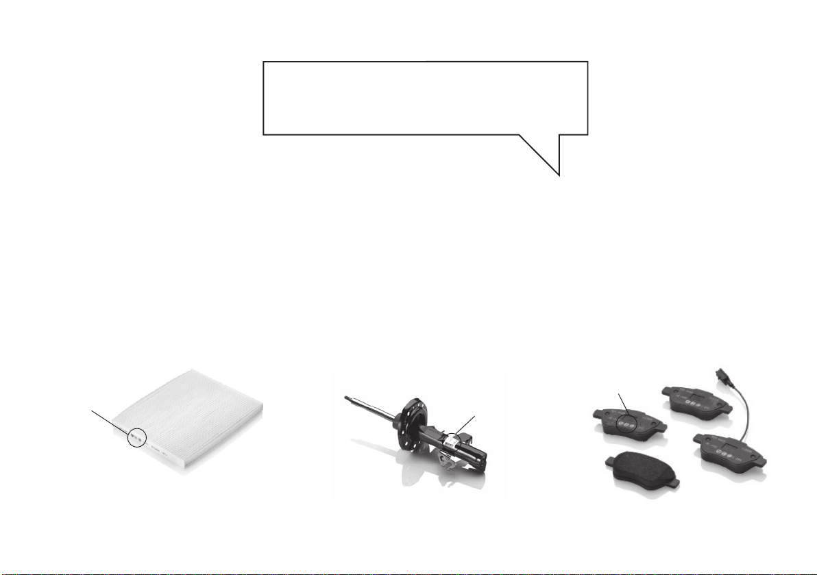
HOW TO RECOGNISE
GENUINE PARTS
Air cleaner
Genuine
Parts
Shock absorber
Genuine
Parts
Brake pads
Genuine
Parts
To recognise a Genuine Part, check that the component bears our brands, always clearly visible on Genuine Parts,
from the braking system to windscreen wipers, from shock absorbers to air cleaner.
All Genuine Parts undergo strict controls, both during design and manufacturing stages,
by specialists using vanguard materials, to test the component reliability.
This to guarantee performance and safety for you and your passengers on board, for a long time.
Always ask for and make sure a Genuine Part has been used.
Page 5

Dear Customer,
We would like to congratulate and thank you for choosing LANCIA.
We have written this handbook to help you get familiar with all the features of your car.
You should read it right through before taking to the road for the first time.
It contains important information, advice and instructions for the use of the car which will help you get the very best
out of your LANCIA.
This handbook also provides a description of special features, essential information for the correct care and maintenance
of your LANCIA as well as safe driving tips.
Read the warnings and indications, marked with the following symbols:
personal safety;
car safety;
environmental protection.
The enclosed Warranty Booklet lists the services that LANCIA offers to its Customers:
arranty Certificate with terms and conditions for maintaining its validity
–the W
– the range of additional services available to LANCIA Customers.
We are sure that these will help you get in touch with your new car and further appreciate it and the care provided by
the people at LANCIA.
Enjoy reading and happy motoring!
This Owner Handbook describes all the versions of the
LANCIA Delta. As a consequence, you should only consider the information which is related to the
trim level, engine and version that you have purchased.
Page 6

ESSENTIAL INFORMATION!
REFUELLING
Use only diesel fuel for motor vehicles compliant with
European specification EN590.
K
The use of other products or mixtures may damage the
engine beyond repair and consequently invalidate the
warranty due to the damage caused.
STARTING THE ENGINE
Turn the ignition key to MAR and wait for the warning lights Y and m to switch off; turn the ignition
key to AVV and release it as soon as the engine starts.
PARKING ON FLAMMABLE MATERIAL
The catalytic converter develops high temperatures during operation. Do not park the car on grass, dry leaves,
RESPECTING THE ENVIRONMENT
pine needles or other flammable material: fire hazard.
The car is fitted with a system that carries out a continuous diagnosis of the emission-r
in order to help protect the environment.
elated components
ELECTRICAL ACCESSORIES
If, after buying the car, you decide to add electrical accessories (that may gradually drain the battery), visit
쇵
a Lancia Dealership. They can calculate the overall
electrical requirement and check that the car’s electric
system can support the required load.
CODE CARD (for versions/markets where provided)
Keep the card in a safe place, not in the car. We recommend that you always carry the electronic code provided on the CODE card with you, in case you need to perform an emergency start.
SCHEDULED SERVICING
Correct car maintenance is essential to ensure that the
performance, safety features, environmental friendliness
and low running costs are unchanged over the years.
THE OWNER HANDBOOK CONT
...important information and warnings on the correct
use and maintenance of your car over time as well as
safe driving tips. Pay special attention to the symbols
(personal safety) #(environmental protection) â
(car safety).
Refer to the “Warning lights on panel” chapter in this handbook
if the message “See Handbook” appears on the display.
AINS…
"
Page 7
SUMMARY
Knowing your car
Safety
Starting and driving
In an emergency
Maintenance and care
Technical specifications
1
2
3
4
5
6
List of contents
7
Page 8

blank page
Page 9

KNOWING YOUR CAR
7
Dashboard .................................................. 8
Control panel and on-board instruments...... 9
Display ....................................................... 26
Menu items ................................................. 30
Trip Computer ............................................ 40
Symbols ...................................................... 42
Lancia Code system..................................... 43
The keys ..................................................... 44
Alarm ......................................................... 48
Ignition switch ............................................ 51
Seats .......................................................... 52
Head restraints ........................................... 55
Steering wheel ............................................ 56
Rear view mirrors ....................................... 56
Climatic comfort ......................................... 58
Manual climate control system .................... 59
Dual-zone automatic climate control system... 61
External lights............................................. 67
Window cleaning ......................................... 70
Cruise Control............................................. 73
Roof lights................................................... 75
Controls ...................................................... 77
Fuel cut-off system...................................... 80
Interior fittings............................................ 81
Sunroof....................................................... 86
Doors .......................................................... 89
Electric windows ........................................ 92
Luggage compartment................................. 96
Bonnet ........................................................ 102
Roof rack/ski rack....................................... 104
Headlights................................................... 105
DST system................................................. 107
SP
ORT function .......................................... 107
Reactive Suspension System ........................ 109
Driving Advisor........................................... 110
Advanced ESP system ................................. 117
EOBD system.............................................. 124
“Dualdrive” electric power
steering system............................................ 125
TPMS system .............................................. 127
Parking sensors ........................................... 131
Magic Parking............................................. 134
Wiring for radio system .............................. 148
Accessories purchased by the owner............. 149
Refuelling the car ........................................ 150
Protecting the environment.......................... 152
1
Page 10

8
KNOWING YOUR CAR
DASHBOARD
The presence and position of controls, instruments and gauges may vary depending on the versions.
fig. 1
L0E0001m
1. Diffuser for sending air to the side windows - 2. Adjustable and directable air diffuser - 3. Exterior lights control
lever - 4. Instrument panel - 5. Windscreen wiper/rear window wiper/trip computer control lever - 6. Adjustable
and directable air diffusers - 7. Hazard warning lights switch - 8. Front passenger airbag - 9. Glove compartment
10. Controls in the dashboard - 11. Climate control system controls - 12. Ignition key and starting device -
13. Driver’s airbag - 14. Driver’s knee bag (for versions/markets where provided) - 15. Steering wheel locking lever -
16. Fuse box access flap - 17. Bonnet release lever.
Page 11
KNOWING YOUR CAR
CONTROL PANEL AND ON-BOARD INSTRUMENTS
9
1
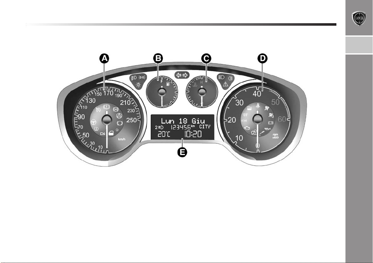
fig. 2
VERSIONS WITH MULTIFUNCTION DISPLAY
A Speedometer (speed indicator)
B Fuel level gauge with reserve warning light
C Engine coolant temperature gauge with overheating warning light
D Rev counter
E Multifunction display
IMPORTANT The type and background colour of the instruments can vary between different versions.
L0E0400m
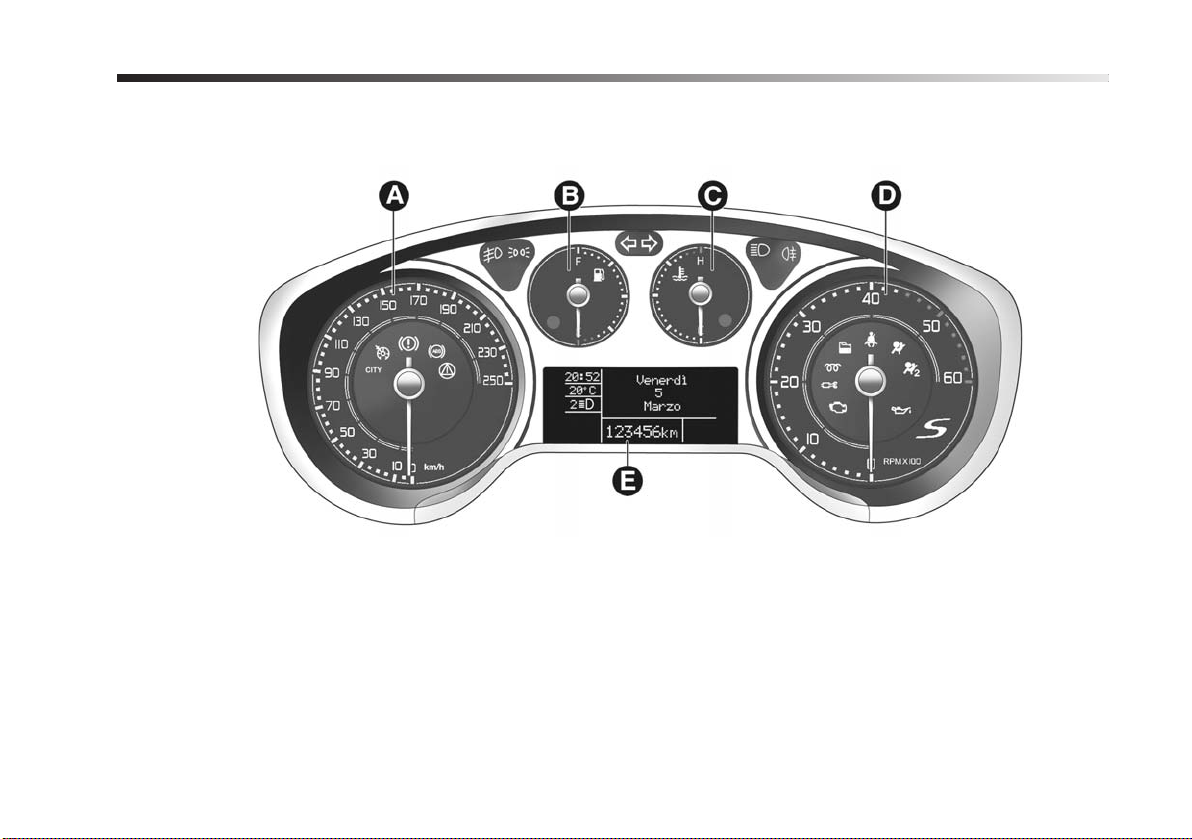
Page 12

10
KNOWING YOUR CAR
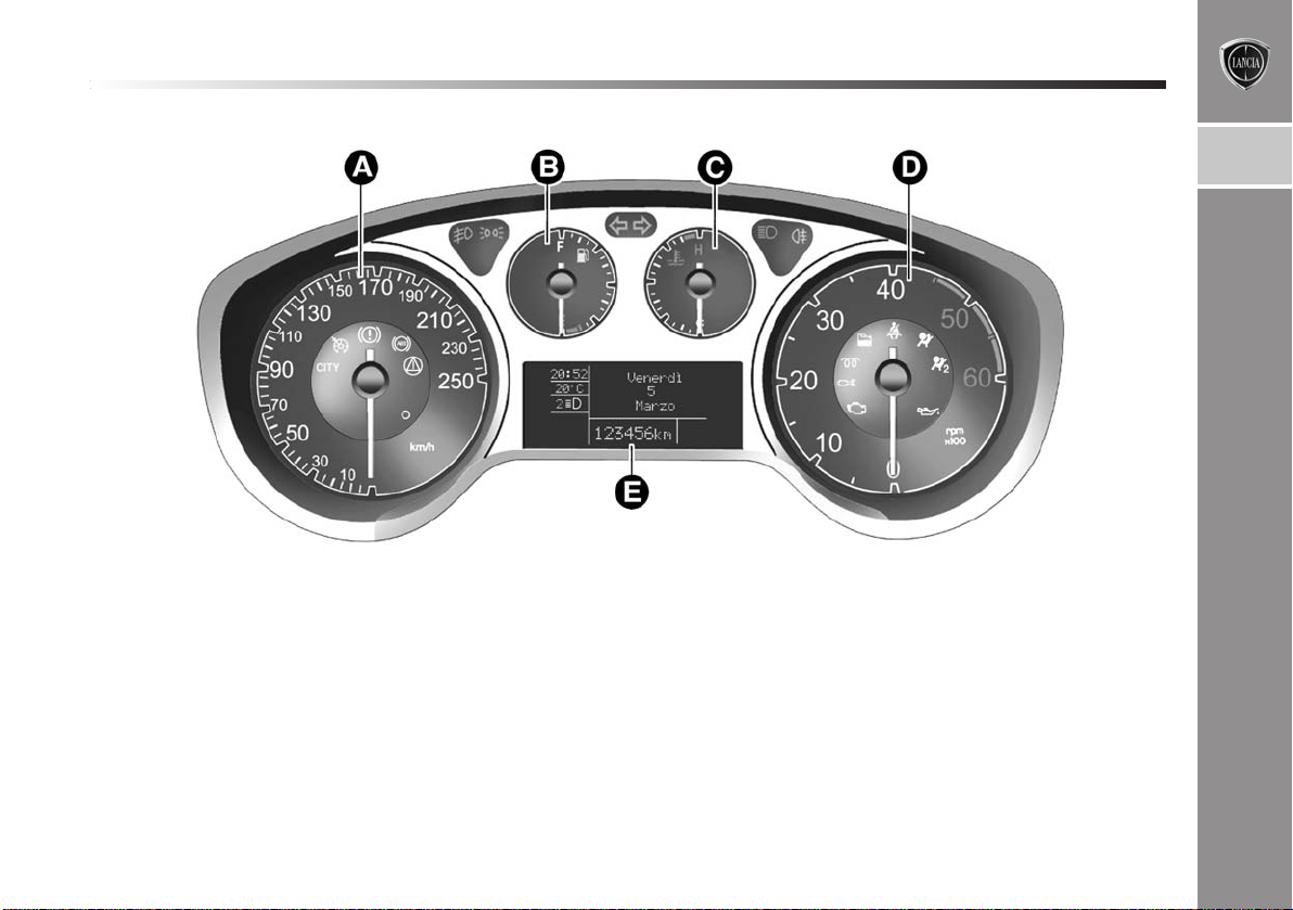
fig. 3
“S” SPECIAL SERIES
A Speedometer (speed indicator)
B Fuel level gauge with reserve warning light
C Engine coolant temperature gauge with overheating warning light
D Rev counter
E Multifunction display
IMPORTANT The type and background colour of the instruments can vary between different versions.
L0E0402m
Page 13
KNOWING YOUR CAR
11
1
fig. 4
VERSIONS WITH RECONFIGURABLE MULTIFUNCTION DISPLAY
A Speedometer (speed indicator)
B Fuel level gauge with reserve warning light
C Engine coolant temperature gauge with overheating warning light
D Rev counter
E Reconfigurable multifunction display.
IMPORTANT The type and background colour of the instruments can vary between different versions.
L0E0401m
Page 14
12
KNOWING YOUR CAR
fig. 5
“S” SPECIAL SERIES
A Speedometer (speed indicator)
B Fuel level gauge with reserve warning light
C Engine coolant temperature gauge with overheating warning light
D Rev counter
E Reconfigurable multifunction display.
IMPORTANT The type and background colour of the instruments can vary between different versions.
L0E0500m
Page 15

KNOWING YOUR CAR
13
SPEEDOMETER (SPEED INDICATOR)
Indicator A shows the speed of the car.
REV COUNTER
Indicator D shows the engine revs.
FUEL LEVEL GAUGE
Indicator B shows the amount of fuel in the tank.
K warning light will switch on (together with a mes-
The
sage on the display) to indicate there are between 5 and
7 litres of fuel remaining.
Do not travel with the fuel tank almost empty: any gaps
in fuel delivery could damage the catalytic converter.
ENGINE COOLANT TEMPERATURE GAUGE
Gauge C shows the temperature of the engine coolant and
indicates when the coolant temperature exceeds 50°C. The
first reference remains on constantly to indicate that the
system is operating correctly. The
es on (together with a message on the display) to indicate that the temperature of the engine coolant has increased significantly. In this event, stop the engine and
go to a Lancia Dealership.
u warning light switch-
INSTRUMENT PANEL WARNING LIGHTS
Important information
The warning lights switch on together with a dedicated
message and/or a buzzer where appropriate. These indications are precautionary and as such must not be considered as exhaustive and/or alternative to the information contained in the Owner Handbook, which you are advised to read carefully in all cases. Always refer to the information in this chapter in the event of a failure indication.
Low brake fluid level (red)
x
on when the brake fluid in the reservoir falls below the
minimum level, possibly due to a leak in the cir
display shows the dedicated message.
Handbrake on (red)
When the key is turned to MAR, the warning light switches on but it should switch off after a few seconds. The
warning light switches on when the handbrake is engaged.
If the car is moving the buzzer will also sound.
IMPORTANT If the warning light turns on when travelling, check that the handbrake is not engaged.
Turning the key to the MAR position illumi-
nates the warning light, but it should switch off
after a few seconds. The warning light switches
cuit. The
1
Page 16
14
KNOWING YOUR CAR
EBD failure
(red)
x
>
the system inspected immediately. The display will show
the dedicated message.
Dealership.
d
them replaced as soon as possible. The display shows the
dedicated message.
IMPORTANT Because the car is equipped with a wear detection system only for the front brake pads, when these
are replaced the rear brake pads should also be checked
for wear.
If warning lights x
on at the same time with the engine running,
this indicates an EBD system failure or that the
system is not available. Early locking of the rear
wheels may occur in the event of sharp braking, possibly causing the car to swerve.
Drive very carefully to a Lancia Dealership to have
If the x warning light turns on when travelling (with the message on the display) stop
the car immediately and contact a Lancia
Brake pad wear (amber)
The warning light (or symbol on the display)
switches on when the front brake pads show
signs of wear; under these circumstances have
and > (amber) are
Airbag failure (red)
¬
stantly if there is a fault in the airbag system.
The display will show the dedicated message.
on the display) there could be a fault in the restraint
systems; under these circumstances, the airbags or
pretensioners may not be deployed in the event of
an impact or, more rarely, they could be deployed
accidentally. Contact a Lancia Dealership to have
the system checked immediately.
that the front passenger airbag is deactivated. In
addition, the airbag system automatically deactivates the passenger side airbags (front airbag and
side bag). In this case, the ¬warning light may not
indicate failures in the retaining systems. Before
proceeding, contact a Lancia Dealership to have the
system checked immediately.
When the key is turned to MAR, the warning
light switches on but it should switch off after
a few seconds. The warning light stays on con-
If the ¬warning light does not come on when
the key is turned to MAR or if it stays on with
the car in motion (together with the message
The failure of the ¬warning light is indicated by the “warning light flashing longer
than the expected 4 seconds, which signals
Page 17

KNOWING YOUR CAR
15
Passenger side airbag/side bags
“
the front passenger airbags activated, when the ignition
key is turned to MAR, the “warning light switches on
constantly for about 4 seconds, flashes for another 4 seconds and should then switch off.
tivates the passenger side airbags (front airbag and
side bag for versions/markets, where provided). Before proceeding, contact a Lancia Dealership to have
the system checked immediately.
<
will flash and a buzzer will sound if the car is in motion
and the front seat belts are not correctly fastened.
The SBR (Seat Belt Reminder) system buzzer can only
be permanently deactivated by a Lancia Dealership.
The system can be reactivated using the Setup Menu.
deactivated (amber)
“
warning light switches on when the front
The
passenger’s airbag and side bag are disabled. With
Failure of the “warning light is indicated
by the ¬warning light coming on. In addition, the airbag system automatically deac-
Seat belts unfastened (red)
This warning light switches on constantly when
the car is not in motion and the driver side seat
belt is not correctly fastened. The warning light
Low battery charge (red)
w
running at idle speed a brief delay before going out is acceptable).
If the warning light stays on, constantly or flashing, contact a Lancia Dealership immediately.
v
comes on, but should go out as soon as the engine is start-
ed.
1. Low engine oil pressure
The warning light switches on constantly together (for ver-
sions/markets, where provided) with the message on the
display when the system detects that engine oil pressure
is low.
engine and contact a Lancia Dealership immediately.
The warning light comes on when the ignition
key is turned to MAR, but it should go out as
soon as the engine has started (with the engine
Continuously on: low engine oil pressure
(red)
Flashing: engine oil deteriorated (red)
When the key is turned to MAR the warning light
If the v warning light turns on when the
car is travelling (on certain versions together with the message on the display) stop the
1
Page 18
16
KNOWING YOUR CAR
2. Degraded engine oil (only versions with DPF)
The warning light will turn on flashing together with the
message on the display (for versions/markets where provided). Depending on the versions, the warning light flashing modes are as follows:
– for 1 minute every two hours;
– cycles of 3 minutes with intervals with the warning light
off for 5 seconds until the oil is changed.
After the first indication, at each engine start up the warning light will continue flashing as described above until
the oil is changed. The display (for versions/markets,
where provided), shows a dedicated message together with
the warning light.
The flashing of the warning light should not be consider
ed as a fault, it simply informs the customer that the
oil needs to be changed following normal car use.
Remember that the deterioration of the engine oil is accel-
erated by:
– mainly town use of the car which makes the DPF re-
generation process more frequent
– use of the vehicle for short drives, in which the engine
does not have time to reach its regular operating temperature
– repeated interruption of the regeneration process, sig-
nalled by the DPF warning light switching on.
Degraded engine oil should be replaced as
soon as possible after the warning light comes
on, and never more than 500 km after it first
comes on. Failure to observe the above indications
may result in severe damage to the engine and invalidate the warranty. Remember that when the
warning light comes on, it does not mean that the
level of engine oil is low, so if the light flashes you
definitely do not need to top up the engine oil.
“Dualdrive” electric power steering
failure (red)
g
after a few seconds.
The electric power steering system will not work when the
warning light is on and considerably more effort is needed
on the steering wheel. The car can still be steered. In this
case, go to a Lancia Dealership. The display will show the
dedicated message.
CITY
tivated by pressing the relevant control button. If the button is pressed again the word CITY goes out.
This warning light switches on when the igni-
tion key is turned to MAR, but it should switch off
“Dualdrive” electric steering engagement
The warning light switches on (or the word
“CITY” appears on the display) when the
“Dual drive” electric power steering system is ac-
Page 19

KNOWING YOUR CAR
17
Engine coolant overheating (red)
u
when the engine is overheated. If the warning light switches on when driving, proceed as follows:
❍ when driving normally: stop the car, switch off the en-
gine and check that the water level in the reservoir is
not below the MIN mark. If it is, wait for the engine
to cool down, then slowly and carefully open the cap,
top up with coolant and check that the level is between
the MIN and MAX marks on the reservoir. Also check
visually for any fluid leaks. in this case, go to a Lancia Dealership if the warning light should switch on
when the engine is started again.
❍ if the vehicle is used under demanding conditions (e.g.
towing trailers uphill or fully loaded): slow down and,
if the light stays on, stop the car
utes with the engine running and slightly accelerated
to further favour the coolant circulation. Then stop the
engine. Check the correct coolant level as described
above.
Turning the key to the MAR position illumi-
nates the warning light, but it should switch off
after a few seconds. The warning light turns on
. Wait for 2 or 3 min-
IMPORTANT Over demanding routes, it is advisable to
keep the engine on and slightly accelerated for a few minutes before switching it off. The display will show the ded-
icated message.
1
Page 20

18
KNOWING YOUR CAR
Doors not closed correctly (red)
´
car moving. The warning light in the multifunction dis-
play also switches on when the bonnet and/or tailgate are
not properly shut. The display will show the dedicated
message.
The warning light switches on when one or
more doors are not completely shut. An acoustic
signal is activated with the doors open and the
General failure indication (amber)
è
venes. The display shows the dedicated message.
Engine oil pressure sensor failure
This warning light (or symbol on the display) switches on
when a fault is detected in the engine oil pressure sensor.
The display shows the dedicated message.
Dusk sensor failure
This warning light (or symbol on the display) switches on
when a fault is detected in the dusk sensor.
Speed limit exceeded
This warning light (amber), or symbol (red) on the dis-
play, switches on when the pr
(for Arab countries the speed limit is set at 120 km/h).
The display shows the dedicated message.
Rain sensor failure
(for versions/markets where provided)
This warning light (or symbol on the display) switches on
when a fault is detected in the rain sensor. The display
shows the dedicated message.
Fuel cut-off activated
This warning light (or symbol on the display)
switches on when the fuel cut-off system inter-
eset speed limit is exceeded
Page 21
KNOWING YOUR CAR
19
Parking sensor fault
(for versions/markets, where provided)
This warning light (or symbol on the display) switches on
when a fault is detected in the parking sensors. The dis-
play shows the dedicated message.
Tyre pressure monitoring system failure
(for versions/markets, where provided)
This warning light (or symbol on the display) switches on
when a failure is detected in the TPMS (for versions/ mar-
kets, where provided).
Should one or more wheels without a sensor be fitted, the
instrument panel warning light will come on and stay on
until the initial conditions are restor
the dedicated message.
NOTE If one of the failures listed above occurs, contact
a Lancia Dealership as soon as possible.
AFS failure
This warning light (or symbol on the display) switches on
when a fault is detected in the AFS (see “Headlights” paragraph in this chapter). The display shows the dedicated
message.
Steering corrector not available
This warning light (or symbol on the display) switches on
when the steering corrector is not available. The display
will show the dedicated message.
ed. The display shows
DPF (diesel particulate filter) cleaning in
h
few seconds. The warning light turns on constantly when
the DPF system needs to eliminate the trapped pollutants
(particulate) thr
The warning light does not come on every time the DPF
is being regenerated, rather only when the driving conditions are such that the driver needs to know it. To switch
the warning light off, the car must be kept moving until
the regeneration process is completed.
On average, the process lasts 15 minutes. The best conditions to complete the regeneration process are reached
driving the car at about 60 km/h with engine speed over
2000 rpm. When this warning light switches on, it does
not indicate a car failure and thus it should not be taken
to a workshop. A dedicated message will appear on the
display when the warning light switches on (for versions/markets, wher
progress (only versions with DPF) (amber)
When the key is turned to MAR, the warning
light switches on but it should switch off after a
ough the regeneration process.
e provided).
1
Page 22

20
KNOWING YOUR CAR
The driving speed must always be suitable
for traffic and weather conditions and the
driver must always comply with the Highway Code. The engine can also be switched off if the
DPF warning light is on; nevertheless, repeated interruptions of the regeneration process could cause
an early deterioration of engine oil. For this reason,
always wait until the warning light switches off before stopping the engine as described above. It is not
advisable to complete DPF regeneration with the
car stationary.
Fuel reserve (amber)
K
when about 5 to 7 litres of fuel are left in the tank.
The display shows the dedicated message.
IMPORTANT The warning light will blink to indicate a sys-
tem failure. Go to a Lancia Dealership to have the system
checked.
U
ed.
When the key is turned to MAR, the warning
light switches on but it should switch off after
a few seconds. The warning light switches on
EOBD/injection system failure (amber)
Under normal conditions, when the ignition key
is turned to MAR, the warning light switches on,
but should switch off as soon as the engine is start-
If the warning light remains on or comes on whilst driving,
it means that the injection system is not working properly; in particular, if the warning light comes on constantly, this indicates a malfunction in the supply/ignition sys-
tem that could cause excessive exhaust emissions, a pos-
sible loss of performance, poor driveability and high fuel
consumption. On some versions the display shows the ded-
icated message. Under these conditions, you may continue travelling at a moderate speed without demanding excessive effort from the engine. Prolonged use of the car
with the warning light on constantly may cause damage.
Go to a Lancia Dealership as soon as possible.
The warning light switches off if the malfunction disappears, but it is still stored by the system.
Go to a Lancia Dealership as soon as possible if U warning light either does not light
up when the key is turned to MAR or if while
travelling the warning light comes on either constantly or flashing (on some versions along with a
message in the display). The operation of the U
warning light may be checked by the traffic control authorities using specific devices. Comply with
the laws and regulations of the country where you
are driving.
Page 23

KNOWING YOUR CAR
21
Advanced ESP system (amber)
á
off or stays on together with the LED on the ASR button
when travelling, contact a Lancia Dealership. On some
versions, the display shows the dedicated message. If the
warning light flashes when driving, this indicates that the
Advanced ESP system is activated.
If the battery is disconnected, the á warning light will
switch on (together with a message in the display) to indicate that the system must be realigned.
To switch the warning light off, carry out the following
initialisation procedure:
❍ turn the ignition key to MAR:
❍ turn the steering wheel fully both clockwise and anti-
clockwise (to move fr
straight);
❍ turn the ignition key to STOP and then to MAR.
If the áwarning light does not go out after a few seconds,
go to a Lancia Dealership.
When the key is turned to MAR, the warning
light switches on but it should switch off after
a few seconds. If the warning light does not switch
om the position with the wheels
Hill Holder failure (amber)
á
*
m
the engine as soon as the warning light switches off.
IMPORTANT In hot outside temperatures, the warning light
may stay on for only a very short time.
Glow plug preheating failure
The warning light flashes if there is a fault in the glow plug
preheating system. Go to a Lancia Dealership as soon as
possible.
The display will show the dedicated message.
The á warning light switches on to indicate
a Hill holder system failure. In this case, contact a Lancia Dealership as soon as possible.
Alternatively, on some versions the * symbol
switches on in the display.
The display will show the dedicated message.
Glow plug preheating
This warning light switches on when the key is
turned to MAR. It will switch off as soon as the
glow plugs have reached a preset temperature. Start
1
Page 24

22
KNOWING YOUR CAR
Water in diesel filter (amber)
c
there is water in the diesel filter. The display will show the
dedicated message.
lights up (on some versions with the message on the display), go to a Lancia Dealership as soon as possible
to have the system bled. Water may have entered the
tank if this appears immediately after refuelling: if this
happens, switch the engine off immediately and contact a Lancia Dealership.
When the key is turned to MAR, the warning
light switches on but it should switch off after
a few seconds. The warning light turns on when
The presence of water in the supply circuit may
cause severe damage to the injection system and
irregular engine operation. If c warning light
ABS failure (amber)
>
when the system is either not working or not available.
In this case the braking system will work as normal, but
without the extra performance offered by the ABS.
Drive carefully and go to a Lancia Dealership as soon as
possible.
The display will show the dedicated message.
When the key is turned to MAR, the warning
light switches on but it should switch off after
a few seconds. The warning light will light up
Page 25
KNOWING YOUR CAR
23
Lancia Code system failure (amber)
Y
Code system”).
If the
ing with engine running, this means that the car is not protected by the engine immobiliser device (see “Lancia
Code system”).
Contact a Lancia Dealership to have all the keys programmed.
Alarm failure
(for versions/markets, where provided)
A failure in the alarm system is signalled by this warning
light (or symbol in the display) switching on. Contact a
Lancia Dealership as soon as possible.
The display shows the dedicated message.
Break in attempt
(for versions/markets, where provided)
This warning light (or symbol on the display) switches on
when a br
Dealership as soon as possible.
The display will show the dedicated message.
This warning light (or symbol on the display),
when on constantly with the ignition key turned
to MAR, indicates a possible failure (see “Lancia
Y
warning light (or symbol in the display) is flash-
eak-in attempt is detected. Contact a Lancia
Insufficient tyre pressure
n
few seconds. The warning light (amber), or symbol in the
display (red), switch on when the inflation pressure of one
or more tyres falls below a preset level. In this way the TPMS
warns the driver and signals the possibility of the tyre be-
ing dangerously deflated and a probable puncture (see para-
graph “TPMS” in this chapter).
IMPORTANT Do not continue driving with one or more
flat tyres as handling may be compromised. Stop the car,
avoiding harsh braking or steering manoeuvres. Replace
the wheel immediately with the space-saver wheel (for
versions/markets wher
using the dedicated kit (see “Changing a wheel” in the
chapter “4”) and contact a Lancia Dealership as soon
as possible.
Check tyre pressures
When the key is turned to MAR, the warning light (for ver-
sions/markets, where provided) switches on, but it should
switch off after a few seconds.
The warning light (or symbol in the display) switches on
to show the flat tyre (see “TPMS” paragraph in this
chapter).
(for versions/markets,where provided)
When the key is turned to MAR, the warning
light switches on, but it should switch off after a
e provided) or carry out a repair
1
Page 26
24
KNOWING YOUR CAR
Should two or more tyres be flat, the display will show the
indications corresponding to each tyre in sequence. Re-
store the correct inflation pressure values as soon as possible (see paragraph “Cold inflation pressures” in chap-
ter “6”).
Tyre pressure unsuitable for speed
When the key is turned to MAR, the warning light (for
versions/markets, where provided) switches on, but it
should switch off after a few seconds.
Should it be necessary to travel at a speed higher than 160
km/h, inflate the tyres more than the pressure value specified in paragraph “Inflation pressures” in chapter “6”.
If the TPMS (for versions/markets where provided) detects that the pr
for the current speed, the warning light or symbol will
switch on (together with the message on the display) (see
“Tyre pressure low” paragraph in this chapter) and it will
stay on until the car slows down to a speed below the pre-
set threshold (see “TPMS” paragraph in this chapter).
IMPORTANT In this case, slow down immediately because
tyre overheating could damage tyre performance and
durability beyond repair, and may even make the tyre explode.
essure of one or more tyres is unsuitable
Particularly strong radio-frequency inter-
ference may cause the TPMS to function in-
correctly. The driver is notified of this condition through a message (for versions/markets,
where provided).
The message will disappear automatically as soon
as the interference ceases to disturb the system.
Exterior lights failure (amber)
W
❍ side lights;
❍ brake lights (for versions/markets where provided);
❍ rear fog lights;
❍ direction indicators;
❍ number plate lights;
❍ daytime running lights.
The failure relating to these lights could be: one or more
blown bulbs, a blown protection fuse or a break in the electrical connection.
The display shows the dedicated message.
This warning light (or symbol on the display)
switches on when a fault is detected in any of
the following lights:
Page 27
KNOWING YOUR CAR
25
4
5
F
D
Rear fog lights (amber)
The warning light comes on when the rear fog
lights are turned on.
Front fog lights (green)
The warning light comes on when the fog lights
are turned on.
Direction indicators
(green - intermittent)
The warning lights switch on when the direction indicator control stalk is moved downwards, upwards or when the hazard warning
light button is pressed.
Daytime running lights/dipped beam
3
tivated.
Follow me home
This warning light switches on when this device is activated (see “Follow Me Home” in this chapter).
The display will show the dedicated message.
1
Ü
few seconds. The warning light is lit up on the display by
rotating the Cruise Control ring nut to ON.
The display will show the dedicated message.
headlights (green)
This warning light switches on when the daytime
running lights or dipped beam headlights are ac-
Main beam headlights (blue)
The warning light switches on when the main
beam headlights are turned on.
Cruise Control (green)
(for versions/markets, where provided)
When the key is turned to MAR, the warning
light switches on but it should switch off after a
1
Page 28

26
KNOWING YOUR CAR
DISPLAY
The car may be provided with a multifunction/reconfigurable multifunction display that shows useful information, according to the previous settings, when driving.
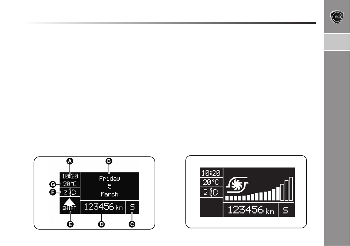
MULTIFUNCTION DISPLAY “STANDARD”
SCREEN fig. 6
The standard screen shows the following information:
A. Date
B. Possible Dualdrive electric power steering engagement
C. Sport driving mode indication
(for versions/markets where provided)
D. Time
E. Milometer (display of distance travelled in kilome-
tres/miles)
F. P o ssible ice on the road indication
G. Outside temperature
H. Scheduled servicing interval
I. Headlight alignment position (only with dipped beam
headlights on).
fig. 6
L0E1000g
Page 29
KNOWING YOUR CAR
27
RECONFIGURABLE MULTIFUNCTION
“STANDARD” DISPLAY fig. 7
The standard screen shows the following information:
A. Time
B. Date
C. Sport driving mode indication (for versions/markets
where provided)
D. Milometer (display of distance travelled in kilome-
tres/miles)
E. Car status indications (e.g. doors open, possible ice on
road, etc.)/Gear Shift Indicator (for versions/markets,
where provided)
F. Headlight alignment position (only with dipped head-
lights on)
G. Outside temperature
On some versions, when the “Engine info” menu item is
selected, the display shows the turbine pressure when the
ignition is turned to the MAR position, fig. 8.
1
fig. 7
L0E1033g
fig. 8
L0E0004m
Page 30

28
KNOWING YOUR CAR
GEAR SHIFT INDICATOR
The GSI system (Gear Shift Indicator) suggests to shift
gear by showing an indication on the control panel (see
fig. 9).
Through the GSI, the driver is notified that the gear change
will allow a reduction in fuel consumption.
When the SHIFT UP icon (N SHIFT) is shown on the dis-
play, the GSI is advising the driver to select a higher gear,
while the SHIFT DOWN (O SHIFT) icon suggests that
a lower gear should be engaged.
NB The indication on the instrument panel remains on until the driver changes gear or until the driving conditions
return to a situation where a gear change is not required,
to reduce consumption.
CONTROL BUTTONS fig. 10
Õ
: To scroll upwards through the displayed menu and the
related options or to increase the displayed value.
SET: press to access the menu and/or go to the next screen
or confirm your choice. Hold down to go back to the stan-
dard screen.
Ô
: to scroll downwards through the displayed menu and
the related options or to decrease the displayed value.
fig. 9
L0E1025g
fig. 10
L0E0005m
Page 31

KNOWING YOUR CAR
29
IMPORTANT Buttons ÕandÔactivate different functions according to the following situations:
– within the menu, they allow you to scroll up and down
through the options;
– during setting operations they increase or decrease the
values.
IMPORTANT When one of the front doors is opened, the
display will switch on and show the clock and km or miles
covered for a few seconds.
SETUP MENU
The menu comprises a series of items which can be select-
ed using the
tion and setting operations (set up) described in the follow-
ing paragraphs. Some options have a submenu. The Setup
Menu can be activated by briefly pressing the SET button.
The menu includes the following items:
– MENU
– LIGHTING
– SPEED BEEP
– LIGHT SENSOR
(for versions/markets, where provided)
– CORNERING LIGHTS
(for versions/markets, where provided)
– TRIP B ACTIVATION/DATA
– SET TIME
– SET DATE
– FIRST PAGE (for versions/markets, where provided)
– SEE RADIO
– AUTOCLOSE
– UNITS OF MEASURE
– LANGUAGE
– W
ARNING VOLUME
– BUTTONS VOLUME
– SEAT BELT BEEP/BUZZ.
– SERVICE
– AIRBAG/PASSENGER BAG
– DAYTIME RUNNING LIGHTS
– EXIT MENU
Õ
and Ôbuttons to access the different selec-
1
Page 32

30
KNOWING YOUR CAR
Selection of an option from main menu
without submenu:
– press the SET button briefly to select the main menu set-
ting you wish to change;
– press
ting;
– press the SET button briefly to store the new setting and
go back to the main menu option selected previously.
Selecting an option from the main menu with a
submenu:
– briefly press the SET button to display the first submenu
option;
– press
the submenu options;
– briefly press the SET button to select the displayed sub-
menu option and to open the relevant settings menu;
– press
option;
– press the SET button briefly to store the new setting and
go back to the previous submenu option.
Õ
or Ô(with single presses) to select the new set-
Õ
or Ô(with single presses) to scroll through all
Õ
or Ôto select the new setting for this submenu
MENU ITEMS
Lighting (Passenger compartment light adjustment)
This function is used to set the brightness of the instrument panel, sound system controls and automatic climate
control system controls (for versions/markets where provided) to 8 levels.
Proceed as follows to adjust the brightness:
– press the SET button briefly to make the display flash
the previously set level;
– press button
– briefly press the SET button to go back to the menu
screen or hold the button down to go back to the standard
screen without saving.
Speed warning (Speed limit)
This function allows the car speed limit to be set (km/h
or mph) and the driver will be notified when it is exceeded (see “Warning lights on panel” section in chapter 1).
To set the desired speed limit, proceed as follows:
– press the SET button briefly, the display will show the
dedicated message;
– press the
(On) or deactivation (Off);
– when the function is activated (On), press the
button to select the desired speed limit and press SET to
confirm the choice.
Õ
or Ôto adjust the brightness level;
Õ
or Ôbutton to select speed limit activation
Õ
or
Ô
Page 33

KNOWING YOUR CAR
31
IMPORTANT Setting is possible between 30 and 200
km/h, or 20 and 125 mph, according to the previously set
unit. See the “Measurement unit adjustment (Measurement unit)” paragraph described below. The setting will
increase/decrease by five units each time
Hold down button
rapidly. Complete the adjustment with single presses of
the button when you approach the desired value.
– briefly press the SET button to go back to the menu
screen or hold the button down to go back to the standard
screen without saving.
To cancel the setting, proceed as follows:
– press the SET button briefly to make the display flash
(On);
– press the
– press the SET button briefly to return to the menu screen
or press the button for longer to return to the standard
screen without memorising.
Ô
Õ/Ô
to increase/decrease the setting
button to make the display flash (Off);
Õ/Ô
is pressed.
Headlight sensor (automatic/dusk sensor
headlights sensitivity adjustment)
(for versions/markets, where provided)
This function is used to adjust the dusk sensor sensitivity to three levels (level 1 = minimum, level 2 = medium,
level 3 = maximum); the higher the sensitivity, the lower
the amount of external light needed to switch the headlights on.
Proceed as follows to set:
– press the SET button briefly to make the display flash
the previously set level;
– p
ress
Õ
or Ôto make your choice;
– briefly press SET to go back to the menu screen or hold
the button down to go back to the standard screen without saving.
1
Page 34

32
KNOWING YOUR CAR
Cornering lights (activation/deactivation of
cornering lights - fog lights with cornering
function) (for versions/markets where provided)
This function activates/deactivates the cornering lights.
To activate/deactivate (ON/OFF) the lights, proceed as
follows:
– press the SET button briefly, the display will show “On”
or “Off” flashing depending on the previous setting;
– press
Õ
or Ôto make your choice;
– briefly press the SET button to go back to the menu
screen or hold the button down to go back to the standard
screen without saving.
Trip B data/activation (Trip B enablement)
This function can be used to activate (On) or deactivate
(Off) the Trip B display (partial trip).
For further information see “Trip computer”.
Proceed as follows to switch the function on/off:
– press the SET button briefly to make the display flash
On or Off depending on the previous setting;
– press
– briefly press SET to go back to the menu screen or hold
the button down to go back to the standard screen without saving.
Õ
or Ôto make your choice;
Time adjustment (Clock adjustment)
This function enables the clock to be set through two submenus: “Time” and “Format”.
To carry out the adjustment, proceed as follows:
– briefly press the SET button and two submenus “Time”
and “Format” are displayed;
– press the
menus;
– once you have selected a sub-menu, press SET briefly;
– when you select “Time”, briefly pressing SET makes the
hours flash on the display;
– press
– briefly press the SET button and the minutes will flash
on the display;
– press
Õ
or Ôbutton to move between the two sub-
Õ
or Ôto adjust the value;
Õ
or Ôto adjust the value.
Page 35

KNOWING YOUR CAR
33
IMPORTANT The setting increases or decreases by one
unit each time button Õor Ôis pressed. Hold down the
button to increase/decrease the setting rapidly and automatically. Complete the adjustment with single presses
of the button when you approach the desired value.
– when you select “Format”, pressing SET briefly makes
the display mode flash on the display;
– press button
When you have made the required settings, briefly press
the SET button to go back to the submenu screen or hold
the button down to go back to the main menu screen without storing the new settings.
– press the SET button again for a long time to return to
the standard screen or to the main menu according to
where you are in the menu.
Õ
or Ôto select “24h” or “12h”.
Set date (Setting the date)
This function may be used to update the date (year –
month – day).
Proceed as follows to update:
– briefly press SET: the “year” flashes on the display;
– press
– briefly press SET: the “month” flashes on the display;
– press
– briefly press SET: the “day” flashes on the display;
– press
IMPORTANT The setting increases or decreases by one
unit each time button Õor Ôis pressed. Hold down the
button to increase/decrease the setting rapidly and automatically. Complete the adjustment with single presses
of the button when you approach the desired value.
Briefly press SET to go back to the menu screen or hold
the button down to go back to the standard screen without saving.
Õ
or Ôto adjust the value;
Õ
or Ôto adjust the value;
Õ
or Ôto adjust the value.
1
Page 36

34
KNOWING YOUR CAR
Initial page
(display of information on the main screen)
(for versions/markets, where provided)
This function allows you to choose the information you
would like to see on the main screen. You can choose to
display the date or the turbocharger supercharging pres-
sure.
To make your choice, proceed as follows:
– briefly press SET: “Initial page” will appear on the dis-
play;
– press the SET button again briefly to display the “date”
and “engine info” options;
– press
on the main page of the display;
– briefly press the SET button to go back to the menu
screen or hold the button down to go back to the standard
screen without saving.
When the key is turned to MAR and the initial check stage
is over, the display will show the information selected via
the “First page” menu function.
Õ
or Ôto select the information you wish to see
See radio (audio information display)
With this function the display shows information about
the sound system.
– Radio: selected station frequency or RDS message, automatic tuning activation or AutoSTore;
– Audio CD, MP3 CD: track number;
– CD Changer: CD number and track number;
To show the radio information on the display (On) or clear
it (Off), proceed as follows:
– briefly press the SET button: the display flashes On or
Off depending on the pr
– press
– briefly press the SET button to go back to the menu
screen or hold the button down to go back to the standard
screen without saving.
Autoclose (Automatic central locking with
car running)
When activated (On), this function locks the doors automatically when the vehicle speed exceeds 20 km/h.
Proceed as follows to activate or deactivate this function:
– press the SET button briefly to display a submenu;
– press the SET button briefly to make the display flash
Õ
or Ôto make your choice;
evious setting;
Page 37

KNOWING YOUR CAR
35
On or Off depending on the previous setting;
– press
– press the SET button briefly to return to the submenu
screen or hold the button down to return to the main menu
screen without saving;
– hold down the SET button again to return to the stan-
dard screen or to the main menu according to where you
are in the menu.
Unit of measurement
(Setting the unit of measurement)
With this function is possible to set the unit of measurement in three submenus: “Distance”, “Consumption” and
“Temperature”. To set the required unit proceed as follows:
– briefly press SET to display the three sub-menus;
– press the
menus;
– once the submenu to be modified has been selected,
briefly press the SET button;
– if the submenu “Distance” is entered: by briefly press-
ing SET the display shows “km” or “mi” depending on
the previous setting;
– press
– when you select “Consumption”, pressing SET button
makes km/l, l/100km or mpg appear on the display depending on the previous setting;
Õ
or Ôto make your choice;
Õ
or Ôbutton to move between the three sub-
Õ
or Ôto make your choice;
If the set distance unit is “km”, the fuel consumption unit
will be displayed in km/l or l/100 km.
If the set distance unit is “mi” the fuel consumption unit will
be displayed in “mpg”.
– press
– when you select “Temperature”, pressing SET makes °C
or °F appear on the display depending on the previous set-
ting;
– press
When you have made the required settings, briefly press
the SET button to go back to the submenu screen or hold
the button down to go back to the main menu screen without storing the new settings.
– press the SET button again for a long time to return to
the standard screen or to the main menu according to
where you are in the menu.
Õ
or Ôto make your choice;
Õ
or Ôto make your choice;
1
Page 38

36
KNOWING YOUR CAR
Language (Language selection)
Display messages can be shown in different languages: Ital-
ian, German, English, Spanish, French, Portuguese and
Dutch.
To set the desired language, proceed as follows:
– briefly press the button SET: the previously set language
starts flashing on the display;
– press
– briefly press the SET button to go back to the menu
screen or hold the button down to go back to the standard
screen without saving.
Warnings volume (Adjusting the failure/warning
acoustic signal volume)
With this function the volume of the acoustic signal which
accompanies the display of failure/warning can be adjusted according to 8 levels.
To set the desired volume, proceed as follows:
– press the SET button briefly, making the display flash
the previously set volume level;
– press
– briefly press SET to go back to the menu screen or hold
the button down to go back to the standard screen without saving.
Õ
or Ôto make your choice;
Õ
or Ôto adjust the value;
Button volume (Adjusting the button volume)
This function enables you to adjust the volume of the
acoustic signal (8 settings) accompanying the activation
Õ
of buttons SET,
To set the desired volume, proceed as follows:
– press the SET button briefly, making the display flash
the previously set volume level;
– press
– briefly press the SET button to go back to the menu
screen or hold the button down to go back to the standard
screen without saving.
Belt reminder
(Buzzer/reactivation for SBR indication)
This function is only displayed after a Lancia Dealership
has deactivated the SBR (see SBR paragraph, chapter
“2”).
Service (Scheduled servicing)
This function allows you to display the information about
km/mileage intervals or, for versions/markets, where
provided, time intervals for car servicing.
Õ
or Ôto adjust the value;
and Ô.
Page 39

KNOWING YOUR CAR
37
To consult this information, proceed as follows:
– briefly press the SET button: the display shows when
servicing is due in km/mi or days (where provided) or
mi or days (where provided) according to the previous set-
ting (see paragraph “Units of measurement”);
– briefly press SET to go back to the menu screen or hold
the button down to go back to the standard screen.
IMPORTANT The “Scheduled Servicing Plan” includes
car maintenance at fixed intervals, refer to the “Maintenance and care” chapter. This is displayed automatically, with ignition key at MAR-ON, 2000 km (or equivalent
value in miles) before servicing or, where provided, 30
days before servicing. It is also displayed each time the
key is turned to MAR-ON or
provided, every 200 km (or equivalent value in miles).
Below this threshold servicing indications are more frequent. The display will be in km or mi depending on the
settings of the unit of measurement. When the next scheduled service is approaching, the word “Service” will appear on the display, followed by the number of kilome-
tres/miles or days (where provided) left, when the key is
turned to MAR-ON. Contact a Lancia Dealership where
the operations of the "Scheduled Servicing Plan" will be
performed and the message will be reset.
When the service interval is reached and for about
1000 km/600 mi or 30 days, a “Service interval elapsed”
message is displayed.
, for versions/markets, where
Airbag/Passenger airbag
This function is used to activate/deactivate the front passenger’s airbag.
Proceed as follows:
– press SET and, after the message Bag pass: Off (to de-
activate) or Bag pass: On (to activate) is displayed by
pressing buttons
–the confirmation request message will be displayed;
– press
tivation) or No (to abort);
– press the SET button briefly, a message confirming the
selection will be displayed and you will return to the menu
screen or, pressing the button for longer, you will return
to the standard screen without memorising.
Õ
Õ
and Ô, press SET again;
or Ôto select Yes (to confirm activation/deac-
1
Page 40

38
KNOWING YOUR CAR
Daytime lights (D.R.L. - Daytime Running Lights)
With this function is possible to turn the daytime running lights on and off.
Proceed as follows to activate or deactivate this function:
– press the SET button briefly to display a submenu;
– press the SET button briefly to make the display flash
On or Off depending on the previous setting;
– press
– press the SET button briefly to return to the submenu
screen or hold the button down to return to the main menu
screen without saving;
– hold down the SET button again to return to the standard screen or to the main menu according to where you
are in the menu.
Menu exit
This is the last function that closes the cycle of settings
listed in the menu screen. Pressing the SET button briefly
will return the display to the standard screen without stor-
ing. Press
Beep).
ÕorÔ
to make your choice;
Ô
to return to the first menu option (Speed
DISPLAY READINGS
IMPORTANT Failure indications displayed are divided
into two categories: very serious and less serious failures.
Ve ry serious faults prompt a prolonged cycle of signals.
Less serious faults prompt a shorter cycle of signals.
The displaying cycle of both failure categories can be
stopped by pressing the button SET. The warning light (or
symbol) will stay on until the fault is eliminated.
R
ed) switches on in the display when the luggage compartment is not properly shut. The display shows the dedicat-
ed message.
S
dedicated message.
Luggage compartment not properly shut
(red)
This symbol (for versions/markets wher
Bonnet not properly shut (red)
This symbol (for versions/markets where pro-
vided) switches on in the display when the bon-
net is not properly shut. The display will show the
e provid-
Page 41

KNOWING YOUR CAR
39
Exterior lights failure (amber)
W
❄
the display to warn the driver of the possible presence of
ice on the road.
The display will show the dedicated message.
e
The symbol switches on in the display when a
fault is detected in the brake lights.
The display shows the dedicated message.
Possible presence of ice on the road
The outside temperature indicator starts flash-
ing when the outside temperature reaches or
falls below 3°C and the
Driving advisor on
The display shows a dedicated message when
the driving advisor function is switched on.
symbol lights up on
❄
Adaptive lights not available
f
è
Lancia Dealership.
õ
Speed limit exceeded
The display shows a dedicated message when the preset
speed limit is exceeded (for Arab countries the speed lim-
it is set at 120 km/h). The icon shown on the display rep-
resents the set speed limit.
The display shows the dedicated message when
the adaptive lights system is not available.
Contact a Lancia Dealership.
Steering corrector not available
(DST - Dynamic Steering Torque)
The display shows a dedicated message
when the steering corrector is faulty. Contact a
Service due
The display shows a specific message to indi-
cate the scheduled servicing deadline.
1
Page 42

40
KNOWING YOUR CAR
TRIP COMPUTER
GENERAL INFORMATION
The Trip computer is used to display information on car
operation when the key is turned to MAR. This function
is composed of separate trips, called “Trip A” and “Trip
B” which can monitor the entire mission (journey) in a
reciprocally independent manner.
Both functions can be reset (reset means start of a new
journey). “Trip A” is used to display the figures relating to:
– Range
– Trip distance
– Average consumption
– Instantaneous consumption
– Average speed
– Travel time (driving time).
– Trip A Reset
“Trip B” may be used to display the figures relating to:
– Distance travelled B
– Average consumption B
– Average speed B
– Trip time B (driving time).
– Trip B Reset
N.B. “Trip B” may be disabled (see “Activating T
“Range” and “Instant consumption” parameters cannot
be reset.
Values displayed
Range
This indicates the approximate distance which can be trav-
elled with the amount of fuel present in the tank. The dis-
play will show the reading ‘----’ when the following events
take place:
– range value lower than 50 km (or 30 mi)
– in case of car parked with engine running for an ex-
tended period.
IMPORTANT The range can be affected by several factors: driving style (see “Driving style” in the “Starting and
driving” chapter), type of route (motorway, towns and
cities, mountain roads, etc.), conditions of use (load, tyre
pressures, etc.). Trip planning must therefore take the
above into account.
Distance travelled
This indicates the approximate distance covered from the
start of the new mission.
rip B”).
Page 43

KNOWING YOUR CAR
41
Average fuel consumption
This value shows the approximate average fuel con-
sumption from the start of the new journey.
Instant fuel consumption
This indicates any change in fuel consumption. The value is constantly updated. The display will show “----” if
the car is parked with the engine running.
Average speed
This value shows the car’s average speed based on the
overall time elapsed since the start of the new journey.
Trip time
Time elapsed since the start of the new journey.
Trip Reset
This resets the Trip computer settings
TRIP control button fig. 11
The TRIP button is located on the right hand lever. With
the ignition key turned to MAR, this button allows you
to view the previously described parameters and also r
set them to begin a new mission:
– brief press to access the various parameter displays;
– long press to reset and then start a new mission.
1
e-
fig. 11
L0E0007m
Page 44

42
KNOWING YOUR CAR
New mission
This begins after a reset:
– “manual” resetting by the user, by pressing the rele-
vant button;
– “automatic” resetting, when the “Trip distance” reach-
es 9999.9 km or when the “Travel time” reaches 99.59
(99 hours and 59 minutes);
– after disconnection/reconnection of the battery.
IMPORTANT The reset operation when “Trip A” details
are being displayed resets the information associated with
this function only.
IMPORTANT The reset operation when “Trip B” details
are being displayed resets the information associated with
this function only.
Start of journey procedure
With the ignition key in the MAR position, reset by press-
ing the TRIP button and keeping it pressed for more than
2 seconds.
T
rip Exit
You can automatically exit the TRIP function once all the
values have been displayed or by holding the SET button down for more than 1 second.
SYMBOLS
Special coloured labels have been attached near to or on
some of the components of your car. These labels bear
symbols that remind you of the precautions to be taken
with regard to that particular component.
A plate summarising these symbols can be found under
the bonnet.
Page 45

KNOWING YOUR CAR
43
THE LANCIA CODE SYSTEM
This is an electronic engine locking system which increases
protection against attempted thefts of the car. It is automatically activated when the ignition key is removed.
Each key contains an electronic device which modulates
the signal emitted during ignition by an antenna built into the ignition device. The signal is the “password”, different every time the car is started, through which the con-
trol unit recognises the key and enables starting.
OPERATION
Each time the car is started by turning the ignition key
to MAR, the Lancia CODE system control unit sends an
acknowledgement code to the engine control unit to deactivate the immobiliser.
The code is sent only if the control unit of the Lancia
CODE system has acknowledged the code received from
the key.
Each time the ignition key is turned to STOP, the Lancia
CODE system deactivates the functions of the management engine contr
If the code is not recognised correctly during ignition, the
Y warning light (or symbol in the display) comes on.
ol unit.
In this case turn the key to STOP and then to MAR; if it
is still locked, try again with the spare set of keys.
Contact a Lancia Dealership if you still cannot start the
engine.
IMPORTANT Each key has its own code which must be
stored by the system control unit. To have new keys pro-
grammed (up to a maximum number of eight keys), contact a Lancia Dealership and be ready to present all the
keys you have in your possession, the CODE card, a personal identity document and the car ownership documents.
The key codes not pr
cedure will be deleted to ensure that any keys that are lost
or stolen cannot be used to start the engine.
Y warning light (or symbol in the display)
switching on whilst driving
❍ If the Y warning light (or symbol in the display)
switches on, this means that the system is running a
self-diagnosis test (caused, for example, by a voltage
drop).
❍ If the Y warning light (or symbol in the display) remains
on, contact a Lancia Dealership.
Violent shocks may damage the electronic
components inside the key.
esented during the programming pro-
1
Page 46

44
KNOWING YOUR CAR
THE KEYS
CODE CARD (for versions/markets, where provided)
A CODE card , fig. 12, is provided together with the vehicle keys. This must be presented to a Lancia Dealership
should you require any duplicate keys.
IMPORTANT In order to ensure perfect efficiency of the
electronic devices contained inside the keys, they should
never be exposed to direct sunlight.
The ignition key and the CODE card must be
handed over to the new owner when selling
the car.
KEY WITHOUT REMOTE CONTROL
(for versions/markets, where provided)
The key is provided with a metal insert A - fig. 13, which
operates:
❍ the ignition switch;
❍ the door locks;
fig. 12
L0E0102m
fig. 13
L0E0103m
Page 47

KNOWING YOUR CAR
45
KEY WITH REMOTE CONTROL fig.14
The key is provided with a metal insert A, which operates:
❍ the ignition switch
❍ the door locks
To open/close the metal insert, press button B.
Button
In this case the timed lighting of interior courtesy lights
and double flashing of direction indicators (for versions/markets where provided) takes place.
Pressing button
opening.
Button
Ë
remotely releases the doors locks.
Ë
for longer than 2 seconds: window
Á
locks all the doors remotely.
In this case the interior roof lights switch off and the direction indicators flash once.
Pressing button
ing.
If one or more door are open, the doors will not be locked.
Button
The opening of the tailgate is signalled by the direction in-
dicators flashing twice; when it is closed there is one flash
(only with the alarm on, for versions/markets where provided).
Button B activates power-assisted opening of metal insert A.
To reinsert the metal insert into the grip, hold down button B and turn the insert in the direction shown by the arrow until you hear it click into place. After locking, release
button B.
R
Á
for longer than 2 seconds: window clos-
is used to open the boot remotely.
1
fig. 14
L0E0104m
Page 48

46
KNOWING YOUR CAR
If the button for locking the doors Áis acci-
dentally pressed from the inside, only the
doors opened for getting out of the car are released;
the tailgate remains locked. To realign the system
the locking/unlocking buttons Á/Ë.
must be pressed again. Only press button B -
fig. 11 when the key is away from the body,
particularly from your eyes and other objects
that may be damaged (e.g. clothing). Do not leave
the key unattended, to prevent people, especially
children, from inadvertently pressing the button.
Request for additional remote controls
The system can recognise up to 8 keys with incorporated
remote control. Should a new remote control be necessary,
contact a Lancia Dealership and be ready to present the
CODE card, a personal identity document and the car’s
ownership documents.
Replacing the battery of a key with remote control
fig. 15
To replace the battery, proceed as follows:
❍ press button A and bring the metal insert B to the open
position;
❍ turn the screw C to : using a fine bit screwdriver;
❍ take out the battery case D and replace the battery E,
respecting its polarity;
❍ refit the battery case D inside the key and lock it by
turning the screw C to Á.
Used batteries are harmful to the environment. They should be disposed of as specified
by law in special containers or taken to a
Lancia Dealership, which will take care of their disposal.
fig. 15
L0E0105m
Page 49

KNOWING YOUR CAR
47
Changing the remote control cover fig. 16
Proceed as shown in the figure to replace the remote
control cover.
SAFE LOCK DEVICE
(for versions/markets where provided)
This safety device inhibits the operation of the interior
door handles and the door locking/unlocking button. We
recommend that you activate this device each time you
park your car.
Activating the device
The device engages on all the doors by quickly doublepressing the
Á
button on the key.
The activation of the device is indicated by three flashes
of the direction indicators and the flashing of the LED
on button A fig. 17. The device will not switch on if one
or more doors are not closed correctly.
1
fig. 16
L0E0106m
fig. 17
L0E0043m
Page 50

48
KNOWING YOUR CAR
Deactivating the device
The device deactivates automatically by:
❍ opening the driver’s door using the metal insert;
❍ pressing the
❍ turning the ignition key to the MAR position
Once the safe lock system is engaged, it is im-
possible to open the doors from inside the car.
Therefore, before getting out of the car check that
there is no one left on board. If the remote control
battery is flat, the device can only be disengaged by
using the metal insert in either of the door locks.
Ë
button on the remote control;
ALARM
(for versions/markets, where provided)
The alarm, in addition to all the remote control functions
described previously, is controlled by the receiver located
under the dashboard near the fuse box.
ALARM ACTIVATION
The alarm intervenes in the following cases:
❍ when a door, the bonnet or the tailgate is opened ille-
gally (perimeter protection);
❍ when the ignition system is operated (ignition key
turned to MAR);
❍ cutting of the battery cables;
❍ movement inside the passenger compartment (volu-
metric protection);
❍ when the vehicle is lifted or tilted.
Depending on the market, the activation of the alarm caus-
es the activation of the siren and the direction indicators
(for about 26 seconds). Alarm tripping and the number
of cycles depend on the sales market.
There is a maximum number of acoustic/visual cycles.
When this is r
ation.
The volume sensing and anti-lift protection can be excluded by adjusting the dedicated control on the front roof
light (see “Volumetric/anti-lift protection”).
eached the system returns to normal oper-
Page 51

KNOWING YOUR CAR
49
IMPORTANT The engine immobiliser function is guaranteed by the Lancia CODE, which is automatically activated when the ignition key is extracted from the starter
device.
TURNING THE ALARM ON
With the doors and bonnet closed and the ignition key
either turned to STOP or removed, point the key with the
remote control towards the vehicle and press and release
Á
button
Excluding some markets, the system produces an acoustic
signal (beep) and enables door locking.
The switching on of the alarm is preceded by a self-diagnosis stage: if a fault is detected, the system emits a new
acoustic signal together with the display of a message (see
“Panel warning lights” chapter).
In this case switch off the alarm by pressing Ë, check that
all the doors, bonnet and tailgate are closed correctly; then
switch the alarm back on by pressing Á.
If a door or the bonnet is not properly shut, it will be excluded from the testing by the alarm system.
If the alarm emits an acoustic signal even when the doors,
bonnet and tailgate are correctly closed, a failure has occurred in system operation. Contact a Lancia Dealership.
.
IMPORTANT Centrally locking the doors using the metal insert on the key does not activate the alarm.
IMPORTANT The alarm is adapted to meet requirements
in various countries.
TURNING THE ALARM OFF
Press button Ëon the key with the remote control.
The following operations are performed (excluding some
markets):
❍ the direction indicators flash briefly twice;
❍ two brief acoustic signals are emitted (“BEEP”);
❍ the doors are unlocked.
IMPORTANT Activating the central opening using the
key’s metal insert does not turn the alarm off.
1
Page 52

50
KNOWING YOUR CAR
VOLUMETRIC/ANTI-LIFT PROTECTION
To guarantee the correct operation of the protection sys-
tem it is advisable to shut all the side windows and the sun
roof (for versions/markets where provided).
If necessary, the function can be turned off (if, for exam-
ple, you are leaving an animal in the car) by pressing but-
ton A-fig. 18, located in the front courtesy light, before
activating the alarm itself.
When the function is disabled, this is indicated by the LED
on the button flashing for several seconds. Any disabling
of the volume sensing/anti-lift protection must be repeated each time the instrument panel is switched off.
BREAK IN ATTEMPT INDICATION
Y
Any break in attempt is indicated by the
warning light
(or symbol in the display) lighting up, together with a mes-
sage shown in the display (see “Instrument panel warning lights” paragraph).
DISABLING THE ALARM
To turn the alarm off completely (for example, if the vehicle is not being used for a long time) the vehicle must be
closed by turning the metal insert in the key in the lock
without using the remote control.
IMPORTANT If the battery of the key with the remote
control runs out or the system fails, the alarm can be
switched off by placing the key in the ignition switch and
turning it to MAR.
fig. 18
L0E0153m
Page 53

KNOWING YOUR CAR
51
IGNITION SWITCH
The key can be turned to 3 different positions fig. 19:
❍ STOP: engine off, key can be removed, steering locked.
Some electrical devices (e.g. sound system, central door
locking system, etc.) can operate.
❍ MAR: driving position. All electrical devices can op-
erate.
❍ AVV: engine starting.
The ignition switch is fitted with a safety system that re-
quires the ignition key to be turned back to STOP if the
engine does not start, before the starting operation can be
repeated.
STEERING LOCK
Activation
When the key is at STOP, remove the key and turn the
steering wheel until it locks.
Disengagement
Move the steering wheel slightly as you turn the ignition
key to MAR.
IMPORTANT In some parking conditions (e.g.: wheels
turned) the effort r
disengage the steering lock may be increased.
Never remove the key while the car is moving. The steering wheel will lock as soon as
it is turned. This holds true for cars being
towed as well. Under no circumstances should aftermarket operations be carried out involving steering system or steering column modifications (e.g.
installation of anti-theft device). This could negatively affect performance and safety, invalidate the
warranty, cause serious safety problems and also
result in vehicle non-compliance with type-approval requirements.
equired to move the steering wheel and
1
fig. 19
L0E0107m
Page 54

52
KNOWING YOUR CAR
SEATS
All adjustments on the front and rear seats
must be made with the car stationary.
After releasing the adjustment levers always
check that the seat is locked into place by try-
ing to move it back and forth. If the seat is not
locked into place, it may unexpectedly slide and
cause the driver to lose control of the car.
FRONT SEATS fig. 20
Longitudinal adjustment
Lift the lever A and push the seat forwards or backwards:
in the driving position your arms should rest on the rim
of the steering wheel.
Backrest angle adjustment
Turn knob B.
fig. 20
L0E0008m
Page 55

KNOWING YOUR CAR
53
Height adjustment
Operate lever C to raise or lower the rear part of the seat
cushion to improve comfort.
Lumbar adjustment (driver’s seat)
The position of the back against the seat backrest is adjusted by turning knob D.
FRONT SEATS WITH ELECTRIC ADJUSTMENT
fig. 21 (for versions/markets where provided
The adjustment is possible with the ignition key to MAR
or for up to 1 minute with the ignition key turned to OFF
or extracted.
When the front doors are opened the seat on the side of
the door that has been opened can be moved for about 3
minutes or until the door is closed.
The controls for seat adjustment are:
Multifunction control A:
❍ seat height adjustment;
❍ lengthwise seat movement.
Multifunction control B:
❍ backrest angle adjustment;
❍ backrest lumbar adjustment.
Seat heating (for versions/markets, wher
With the key turned to MAR, press buttons
the function on/off.
When the function is enabled, the LED on the button turns
on.
e provided)
C
to switch
1
fig. 21
L0E0009m
Page 56

54
KNOWING YOUR CAR
REAR SEATS
Backrest angle adjustment
Lift lever A - fig. 22 (one on each side) for backrest angle adjustment, for the left or right part of the backrest re-
spectively (to facilitate this operation, slightly move the
seat forwards using lever B).
Rear seat movement
(for versions/markets, where provided)
The rear seats can be moved backwards and forwards (by
80 mm). To move the seats backwards or forwards operate the levers B (one on each side).
“Fixed” type rear seats
(for versions/markets, where provided)
In some versions, rear seats are “fixed” type and the back-
rest angle adjustment is possible if the luggage compartment is extended. Use lever A-fig. 23 (one each side) for
backrest angle adjustment.
When repositioning the rear backrest during its movement, check that it has been attached correctly, grasping the backrest at the
top and shaking it.
Before tilting the backrests, make sure that the
seat belts are fully stretched, without any
twisting.
fig. 22
L0E0010m
fig. 23
L0E0231m
Page 57

KNOWING YOUR CAR
55
HEAD RESTRAINTS
Head restraints are height adjustable; operate as follows.
❍ Upwards adjustment: lift the head restraint until it
locks.
❍ Downward adjustment, press the button A and lower
the head restraint.
All adjustments must be carried out only with
the vehicle stationary and engine off. Head
restraints must be adjusted so that the head,
rather than the neck, rests on them. Only in this case
can they protect your head correctly. To make the
best use of the head restraint’s protective action, adjust the backrest so that your torso is upright and
keep your head as close as possible to the head restraint.
REAR HEAD RESTRAINTS fig. 24
(for versions/markets, where provided)
Depending on the versions, rear head restraints can be
“fixed” or height-adjustable type.
Height-adjustable head restraint:
❍ Upwards adjustment: press button B and lift the head
restraint until it locks.
❍ Downward adjustment, press button B and lower the
head restraint.
To extract the rear head restraints press buttons B and C
at the side of the two supports simultaneously and lift them
out upwards.
IMPORTANT When the rear seats are in use, the head
restraints must always be in the position of use.
fig. 24
L0E0011m
1
Page 58

56
KNOWING YOUR CAR
STEERING WHEEL
It can be adjusted vertically (and axially).
To adjust the steering wheel, move the lever fig. 25 upwards to position 1. Adjust the steering wheel into the most
suitable position and lock it in this position by moving the
lever to position 2.
Any adjustments must be carried out only
with the car stationary and engine off.
REAR VIEW MIRRORS
INTERNAL REAR VIEW MIRROR fig. 26
The mirror is fitted with a safety device that causes its
release in the event of a violent impact with the passenger.
Lever A can be used to move the mirror to two different
positions: normal or antiglare.
INTERNAL ELECTROCHROMIC REAR VIEW
MIRROR (for versions/markets, where provided)
Some versions have an electrochromic mirror with automatic antiglare function.
When reverse gear is engaged, the mirror is automatically set for daytime use.
fig. 25
L0E0012m
fig. 26
L0E0013m
Page 59

KNOWING YOUR CAR
57
DOOR MIRRORS
Mirror electric folding fig. 27
(for versions/markets, where provided)
Proceed as follows to adjust the position of the door mirrors:
❍ select the mirror using selector B;
❍ adjust the mirror using the controls A, in all four di-
rections.
Mirror manual folding fig. 28
When required (for example when the mirror causes difficulty in narrow spaces) it is possible to fold the mirror
by moving it from position 1 (open), to position 2
(closed).
On some versions the door mirrors can be folded back elec-
trically by operating a dedicated control.
When driving, the mirrors should always be
in position 1. As the door mirrors are curved,
they may slightly alter the perception of dis-
tance.
1
fig. 27
L0E0014m
fig. 28
L0E0015m
Page 60

58
CLIMATE COMFORT
KNOWING YOUR CAR
fig. 29
L0E0016m
DIFFUSERS fig. 29
1. Diffusers for windscreen defrosting or demisting – 2. Centre directable and adjustable diffusers – 3. Side directable
and adjustable diffusers – 4. Fixed diffusers for side windows – 5. Lower diffusers – 6. Rear directable and adjustable vent
(for versions/markets, where provided).
Page 61

KNOWING YOUR CAR
MANUAL CLIMATE CONTROL SYSTEM
59
1
fig. 30
CONTROLS fig. 30
A. Air temperature knob (red = hot/blue = cold)
B. Fan speed knob.
C. Air distribution knob
μ toward the body and the side windows
∑ toward the body, the side windows and the feet
L0E0017m
∂ toward the feet only
∏ toward the feet and the windscreen
- toward the windshield only.
Page 62

60
KNOWING YOUR CAR
IMPORTANT It is advisable to activate air recirculation
in queues or in tunnels to prevent the introduction of polluted air. However, it is better not to use the function for
long periods, particularly if there are many people on
board, to prevent the windows from misting.
D. Air recirculation on/off button
(LED lit up when function is on).
E Manual climate control compressor on/off button (LED
lit up when function is on).
F Heated rear window activation/deactivation button.
When the function is active, an LED on the button is
lit up. In order to maintain battery efficiency, the func-
tion is automatically deactivated after about 20 minutes.
FAST WINDSCREEN AND FRONT SIDE
WINDOW DEMISTING/DEFROSTING (MAX-DEF)
Proceed as follows:
❍ turn knob A to the red section;
❍ turn knob C to
❍ turn knob D to -;
❍ turn knob B to 4 - (maximum fan speed).
IMPORTANT The climate control system is very useful
for fast demisting because it dries the air. Adjust the controls as described above and press knob B to switch the
climate control system on: the LED on the knob will light
up.
SYSTEM SERVICING
In winter, the climate control system must be turned on at
least once a month for about 10 minutes. Have the system inspected at a Lancia Dealership before the summer.
Ú;
Page 63

KNOWING YOUR CAR
DUAL-ZONE AUTOMATIC CLIMATE CONTROL SYSTEM
(for versions/markets, where provided)
61
1
fig. 31
The vehicle may be equipped with a dual zone automatic
climate control system, fig. 31, which regulates the pas-
senger side air temperature separately from the driver’s
side.
L0E0018m
The system is equipped with an AQS (Air Quality
System) (for versions/markets, where provided) function,
which automatically switches on the air recirculation sys-
tem if the outside air is polluted (e.g. in traffic queues and
tunnels).
Page 64

62
KNOWING YOUR CAR
SWITCHING ON THE CLIMATE
CONTROL SYSTEM
The system can be activated by pressing any of the buttons; it is, however, advisable to set the desired temperatures on the display, then press the AUTO button.
The climate control system allows you to customise the
temperatures requested (driver side and passenger side)
with a maximum difference of 7°C.
The climate control system compressor only works with
the engine running and with an outside temperature above
4°C.
Automatic climate control operation
(AUTO function) A - fig. 31
Press the AUTO button; the system will automatically adjust:
❍ the amount of air introduced into the passenger com-
partment;
❍ the distribution of air inside the passenger compart-
ment;
cancelling any previous manual settings.
During climate control system automatic operation, the
words FULL AUTO appear on the display.
During automatic operation it is still possible to adjust the
temperatures set and carry out one of the following operations manually:
❍ adjust fan speed;
❍ select air distribution;
❍ switch internal air recirculation and AQS function
on/off (for versions/markets, where provided);
❍ switch on the climate control system compressor.
It is advisable not to use the internal air recirculation function when the outside temperature is low to prevent the windows from
rapidly misting up.
Page 65

KNOWING YOUR CAR
63
Selecting air distribution B - fig. 31
/
/
Press one or more of buttons
lect one of the 7 possible air distribution settings for the
passenger compartment:
Air flow to the windscreen and front side window diffusers to demist/defrost them.
Air flow to the front and rear footwell diffusers. This
air distribution allows the passenger compartment to
be warmed up quickly.
Air flow distribution between the
front and rear diffusers, centre/side dashboard
˙
diffusers, rear diffuser and windscreen and front side
window demisting/defrosting diffusers.
Air flow distribution between the footwell
diffusers and the windscreen and front side window
demisting/defrosting diffusers. This distribution set-
ting allows the passenger compartment to be warmed
up efficiently and prevents the windows from mist-
ing up.
˙
Air flow distribution between footwell diffusers (hot-
ter air) and centre/side dashboard diffusers and rear
diffuser (cooler air).
˙ to manually se-
˙ Air flow distribution between centre/side dashboard
diffusers, rear diffuser and windscreen and front side
window demisting/defrosting diffusers. This distri-
bution setting ventilates the passenger compartment
well and prevents the windows from misting up.
IMPORTANT For the climate control system to function, at
least one of the following buttons must be on:
The system does not allow all the buttons
switched off.
IMPORTANT Push the OFF button to turn the climate
control system back on: in this way, all operating condi-
tions saved before switching off are restored.
To restore automatic control of the air distribution after
a manual selection, press the AUTO button.
/
/
/
˙ to be
/
˙.
1
Page 66

64
KNOWING YOUR CAR
Adjusting the fan speed fig. 31
Operate buttons C
fan.
The 12 possible speeds are indicated by bars lighting up
on the display:
❍ max fan speed = all bars lit
❍ min. fan speed = one bar lit.
The fan can be disabled (no bars lit) only if the climate
control compressor has been switched off by pressing button
.
❄
To restore automatic fan speed control after a manual adjustment, press AUTO.
to increase/decrease the speed of the
p
Aligning the set temperatures
(MONO function) fig. 31
Press button D (MONO) to align the temperature between
the driver side and passenger side.
Then turn the AUTO or MONO knob to increase/decrease
the temperature between the two areas by the same
amount.
Press MONO again to deactivate the function.
Switching off the climate control system fig. 31
Press button E (OFF).
The following information is shown on the display:
❍ the word OFF;
❍ outside temperature reading;
❍ indication that air recirculation is switched on (LED
on button
T
is lit).
Page 67

KNOWING YOUR CAR
65
Heated rear window and door mirrors
demisting/defrosting fig. 31
(
Press button F
vated, the button LED lights up.
This function is timed and will turn off automatically after 20 minutes. Press the button (again to switch the
function off.
IMPORTANT Do not apply stickers on the inside of the
rear window over the heating filaments to avoid damage.
IMPORTANT Press
side (in this case the LED on the button is off).
to activate; when this function is acti-
to introduce air from the out-
T
Rapid front window demisting/defrosting
(MAX-DEF function) fig. 31
Press button G -to automatically activate the timed operation of all the functions required to rapidly demist/defrost the windscreen and front side windows.
The functions are:
❍ climate control compressor engagement (with an out-
side temperature of above 4°C);
❍ switching off, if previously on, of the interior air re-
circulation (LED on button
❍ switching on of heated rear window (LED on button
on) and door mirror heater coils;
-
❍ air temperature set to maximum;
❍ activation of air flow.
T
off);
1
Page 68

66
KNOWING YOUR CAR
Activation of air recirculation and enablement of
AQS (Air Quality System)
(for versions/markets, where provided) fig. 31
Press button
Internal air recirculation is carried out according to three
possible operating modes:
❍ automatic control, signalled by the AQS sign on the
display and the LED on button
❍ permanently off (air recirculation always off with in-
troduction of external air), indicated by the LED on
button
❍ permanently on (air recirculation always on), signalled
by the LED on button
When OFF is pressed, the climate control system automatically activates internal air recirculation (LED on button
circulation (LED on the button off) and vice versa, by
pressing button
With the OFF button pressed (LED on the button is lit
up), it is not possible to enable the AQS (Air Quality Sys-
tem) function.
T
on). It is still possible to activate outside air re-
T
T
being off;
T
.
being off;
T
being lit up.
T
.
IMPORTANT The internal air recirculation system makes
it possible to reach the required heating or cooling con-
ditions faster depending on the mode selected. It is not advisable to switch the air recirculation on when it is
rainy/cold to prevent the windows from misting up, es-
pecially if the climate control is not turned on. It is advisable to switch the internal air recirculation on whilst
queuing or in tunnels to prevent the introduction of polluted air. Do not use the function for a long time, particularly if there are several passengers on board, to prevent the windows from misting up.
Enabling the AQS (Air Quality System) function
(for versions/markets, where provided)
The AQS function (AQS appears on the display), automatically activates internal air r
side air is polluted (e.g. in traffic queues and tunnels).
IMPORTANT With the AQS function active, after 15 con-
secutive minutes of the internal air recirculation system
functioning, the climate control system enables the intake
of outside air for approximately 1 minute to freshen the
air in the passenger compartment. This takes place regardless of the pollution level of the outside air.
ecirculation when the out-
Page 69

KNOWING YOUR CAR
67
Switching the climate control compressor on/off
I - fig. 31
Press button
compressor.
Compressor engagement
❍ the LED on button
❍ symbol
Compressor off
❍ the LED on button
❍ symbol
❍ internal air recirculation is excluded;
❍ the AQS function is disabled.
With the climate control compressor switched off, air cannot be introduced into the passenger compartment at a
lower temperature than the outside temperature; in this
case the
The deactivation of the climate control compressor is
memorised even after the engine has stopped. To turn the
climate control compressor back on, press button ❄again
or press AUTO: if you press AUTO, the other manual set-
tings will be cancelled.
❄
to switch on the climate control system
❄
is lit up;
❄
is shown on the display.
❄
is off;
❄
off on the display;
❄
symbol on the display will flash.
EXTERNAL LIGHTS
1
The left stalk fig. 32 operates most of the external lights.
The ignition key has to be in the MAR position for the
exterior lights to come on. The instrument panel and the
various dashboard controls will come on with the external lights.
DAYTIME RUNNING LIGHTS (DRL)
(for versions/markets where provided)
With the ignition key turned to MAR and the twist switch
turned to position O the daytime running lights are automatically activated; the other lights and interior lighting remain off. The automatic operation of the daytime
running lights can be activated/deactivated via the dis-
play menu (see “Display” paragraph in this chapter). If
the daytime running lights are deactivated, no light comes
on when the twist switch is turned to O.
fig. 32
L0E0019m
Page 70

68
KNOWING YOUR CAR
The daytime running lights are an alternative to the dipped beam headlights for driving
during the daytime in countries where it is
compulsory to have lights on during the day, and
they are also permitted in those countries where this
is not obligatory.
Daytime running lights cannot replace dipped beam
headlights when driving at night or through tunnels.
The use of daytime running lights is governed by
the highway code of the country in which you are
driving. Comply with the prescriptions.
AUTOMATIC HEADLIGHT SENSOR (dusk sensor)
(for versions/markets, where provided)
It detects variations in brightness outside the vehicle depending on the light setting: the greater the sensitivity, the
less outside light needed to activate the exterior lights being turned on. The sensitivity of the dusk sensor may be
adjusted, using the “Setup menu” on the instrument panel.
Activation
When the ring nut is turned to the AUTO position the
external lights automatically switch on depending on the
exterior brightness.
The headlights can only be flashed with the sensor on.
Deactivation
When the lights are switched off by the sensor, the dipped
beam headlights and side lights are switched off and the
day lights are switched on (if activated).
The sensor is not capable of detecting the presence of fog
therefore, in these circumstances, the lights have to be
turned on manually.
FRONT FOG LIGHTS WITH
CORNERING LIGHTS FUNCTION
When the dipped beam headlights are on and the speed is
below 40 km/h, if the steering wheel rotation angle is large
or the direction indicators are on, a light (incorporated
in the fog light) will come on on the relevant side to im-
ove visibility at night time. The function can be acti-
pr
vated/deactivated via the display menu (see “Display”
paragraph in this chapter).
Page 71

KNOWING YOUR CAR
69
DIPPED BEAM HEADLIGHTS/SIDE LIGHTS
With the ignition key turned to MAR, turn the twist switch
to 2. If the dipped beam headlights are activated, the
daytime running lights are switched off and the side lights,
dipped beam headlights and number plate lights are
switched on. The
warning light on the instrument pan-
3
el comes on. When the ignition key is turned to STOP or
removed and the twist switch is turned from Oto 2, all
the side lights and number plate lights come on. The
3
warning light in the instrument panel comes on.
Parking function
With the side lights on and the ignition key in the OFF po-
sition or extracted, it is possible to select the lighting on
the desired side by operating the lights lever downwards
(left side) or upwards (right side). In this case the
3
warning light in the instrument panel will go out.
MAIN BEAM HEADLIGHTS
With twist switch in position 2, push the stalk forward
toward the dashboard (stable position). The 1 warning
light on the instrument panel will come on. They are
switched off by pulling the lever towards the steering
wheel.
DIRECTION INDICATORS fig. 33
Bring the stalk to the (stable) position:
– up (position
– down (position
¥
or Îwarning light starts flashing on the instrument
The
a
): activates the right direction indicator;
b
): activates the left direction indicator.
panel. The direction indicators switch off automatically
when the steering wheel is straightened.
1
Flashing
You can flash the beams pulling the stalk toward the steering wheel (unstable position). The
1 warning light on the
instrument panel will come on.
fig. 33
L0E0020m
Page 72

70
KNOWING YOUR CAR
LANE CHANGE FUNCTION
If you wish to signal a lane change, place the left stalk in
the unstable position for less than half a second. The direction indicator on the side selected will flash five times
and then switch off automatically.
“FOLLOW ME HOME” DEVICE
This allows the space surrounding the car to be lit up for
a certain period of time.
Activation
With the ignition key in the STOP position or extracted,
pull the stalk towards the steering wheel and move it within 2 minutes of the engine switching off. Each time the
stalk is moved, the lights stay on for an extra 30 seconds
up to a maximum of 210 seconds; then the lights are
switched off automatically. Each time the lever is oper-
ated, the warning light 3 on the instrument panel comes
on and the display shows how long the function will r
main active. The warning light comes on when the stalk
is pulled for the first time and stays lit until the function
switches itself off automatically. Each time the stalk is ac-
tivated it increases the time that the lights remain on.
Deactivation
Keep the stalk pulled towards the steering wheel for more
than two seconds.
e-
WINDOW CLEANING
The right-hand lever fig. 34 controls windscreen wiper/
washer and rear window wiper/washer operation.
WINDSCREEN WIPER/WASHER
This operates only with the ignition key turned to
MAR.
The right hand lever can take up five different positions:
A: windscreen wiper off.
B: intermittent operation.
With the stalk in position B, turn ring nut F to select one
of four different speeds for the intermittent operation
mode:
, = very slow intermittent operation
■ = slow intermittent operation.
■■ = normal intermittent operation
■■■ = fast intermittent operation.
C: continuous slow operation;
D: continuous fast operation;
E: temporary fast operation (unstable position).
Page 73

KNOWING YOUR CAR
71
“Smart washing” function
Pull the stalk towards the steering wheel (unstable position) to operate the windscreen washer. Keep the lever
pulled to activate both the windscreen washer jet and the
windscreen wiper with a single movement; the latter turns
on automatically if you keep the lever pulled for more than
half a second. The windscreen wiper stops operating a few
strokes after releasing the stalk; a further “cleaning
stroke”, after a few seconds, completes the wiping oper-
ation.
fig. 34
L0E0021m
REAR WINDOW WASHER/WIPER
This operates only with the ignition key turned to MAR.
Turn the ring nut to
With the windscreen wiper on, turn the ring nut to 'to
turn on the rear window wiper. In this case the wiper works
(in the different positions) timed with the windscreen
wiper, but at half speed. With the windscreen wiper on,
engaging reverse gear will automatically turn the rear window wiper on, in continuous slow operation. Operation
stops when reverse is disengaged.
Do not use the windscreen or rear window
wiper to remove layers of snow or ice from
the windscreen. In such conditions, the wiper
may be subjected to excessive stress and the motor
protection, which prevents operation for a few seconds, may intervene. If rear window wiper operation is not reset, contact a Lancia Dealership.
“Smart washing” function
Pushing the stalk towards the dashboard (unstable position) will activate the rear window washer.
Keep the stalk pressed, with just one movement, to operate
the rear window washer jet and the rear window wiper itself; the latter automatically turns on if you keep the stalk
pressed for more than half a second.
to operate the rear window wiper.
‘
1
Page 74

72
KNOWING YOUR CAR
The rear window wiper stops operating a few strokes after releasing the stalk; a further “cleaning stroke”, after
a few seconds, completes the wiping operation.
RAIN SENSOR
(for versions/markets where provided)
The rain sensor A - fig. 35 is located behind the internal
rear view mirror in contact with the windscreen and automatically adjusts the frequency of the windscreen wiper
strokes according to the rain intensity during intermittent
operation.
The sensor has an adjustment range that varies progres-
sively from wiper still (no stroke) when the windscreen
is dry, to wiper at first continuous speed (slow continu-
ous operation) with intense rain.
Activation
Move the right lever down by one click.
The activation of the sensor is signalled by a “stroke” to
show that the command has been acquired.
IMPORTANT Keep the glass in the sensor area clean.
By turning ring nut F - fig. 34 it is possible to increase the
sensitivity of the rain sensor to obtain a more rapid variation between wiper still (no stroke) when the windscreen
is dry, to wiper at first continuous speed (slow continu-
ous operation).
The increasing of the rain sensor sensitivity is signalled by
a “stroke” to show that the command has been acquired.
Activating the windscreen washers with the rain sensor
activated pr
oduces the normal washing cycle at the end of
which the rain sensor resumes its normal automatic operation.
fig. 35
L0E0023m
Page 75

KNOWING YOUR CAR
73
Deactivation
Turn the ignition key to STOP.
The next time the vehicle is started (ignition key turned
to MAR), the sensor is not reactivated even if the lever is
still in position B - fig. 34. To activate the sensor, move
the lever to position A or C and then back to position B.
Rain sensor activation will be indicated by at least one
wiper “stroke” even if the windscreen is dry.
Do not activate the rain sensor when washing the car in an automatic car wash.
Make sure the device is switched off if there
is ice on the windscreen.
Make sure the device is switched off whenever the windscreen is being cleaned.
CRUISE CONTROL
(constant speed regulator)
(for versions/markets, where provided)
This is an electronically controlled driving assistance device which allows the vehicle to be driven at a chosen speed
above 30 km/h on long stretches of dry, straight roads with
few variations (e.g. motorways), without having to depress
the accelerator pedal.
It is therefore not recommended to use this device on extra-urban roads with traffic. Do not use it in town.
ACTIVATING THE DEVICE
Turn selector wheel A - fig. 36 to ON.
The device must only be switched on in gears higher
than 4th.
1
fig. 36
L0E0022m
Page 76

74
KNOWING YOUR CAR
When travelling downhill with the device engaged, the vehicle speed may slightly exceed the preset one.
The engagement of the device is signalled by the Ü warn-
ing light coming on in the instrument panel (together with
a message shown on the display) (see “Instrument panel
warning lights” paragraph).
STORING THE CAR SPEED
Proceed as follows:
❍ turn the ring nut A - fig. 36 to ON and press the ac-
celerator pedal until the vehicle reaches the desired
speed;
❍ turn the ring nut to (+) for at least three seconds, then
release it. The vehicle speed is now memorised and you
can therefore release the accelerator pedal.
If needed (when overtaking for instance), you can accelerate simply by pressing the accelerator pedal; when you
release the pedal, the car will r
rised previously.
RESTORING THE MEMORISED SPEED
If the device has been switched off, for example by depressing the brake or clutch pedal, the memorised speed
can be restored as follows:
❍ accelerate gradually until reaching a speed approach-
ing the memorised speed;
eturn to the speed memo-
❍ engage the gear selected at the time of speed memo-
rising (fourth, fifth or sixth gear);
❍ press button C - fig. 36.
INCREASING THE MEMORISED SPEED
This can be done in two ways:
❍ by pressing the accelerator and then memorising the
new speed reached;
or
❍ by temporarily turning ring nut B - fig. 36 to (+).
Each movement of the selector wheel will correspond to
a slight incr
the selector wheel turned will correspond to a continuous speed increase.
REDUCING THE MEMORISED SPEED
This can be done in two ways:
❍ by disengaging the device and then memorising the
new speed;
or
❍ by keeping ring nut B - fig. 36 turned to (–) until the
new speed is reached; it will then be memorised auto-
matically.
Each movement of the ring nut will correspond to a re-
duction in speed of about 1 km/h, while keeping the ring
nut turned will correspond to a continuous reduction in
speed.
ease in speed (about 1 km/h), while keeping
Page 77

KNOWING YOUR CAR
75
DEACTIVATING THE DEVICE
Turn the ring nut A - fig. 36 to OFF or turn the ignition
key to STOP. The device is automatically turned off in one
of the following cases:
❍ when the brake or clutch pedal is pressed;
❍ if the ASR or Advanced ESP system cuts in (for ver-
sions/markets where provided);
While travelling with the device engaged, do
not place the gear lever in neutral.
In case of malfunction or if the device is faulty,
turn the control A - fig. 36 to OFF and contact a Lancia Dealership, after checking that
the protective fuse has not blown.
ROOF LIGHTS
1
FRONT ROOF LIGHT WITH SPOT LIGHTS fig. 37
Switch A is used to switch on/off roof lights.
With the switch A in the middle position, the lights C and
D go on/off when front doors are opened/closed.
With switch A pressed to the left, the lights C and D are
always off. With switch A pressed to the right, the lights
C and D are always on.
Lights switch on/off progressively.
Switch B controls the spot light function; when the roof
light is off, it switches on individually:
❍ the light C when pressed to the left;
❍ the light D when pressed to the right.
fig. 37
L0E0024m
Page 78

76
KNOWING YOUR CAR
For versions/markets, where provided the roof light, some
bulbs light the car interior when the main beam headlights
or dipped beam headlights are on.
IMPORTANT The roof light, for some versions, may also
be in a rear central position (electric sun roof version).
IMPORTANT Before getting out of the car, make sure both
switches are in the middle position; when the doors are
closed, the lights switch off preventing a possible discharge
of the battery. In any case, if the switch is left in on posi-
tion, the roof light switches off automatically 15 minutes
after the engine switching off.
Roof light timing
To make getting in and out the vehicle easier, especially
at night time or in poorly lit areas, two timing logic are
available.
Timing while getting into the vehicle
The roof lights switch on according to the following modes:
❍ for ar
ound 10 seconds when the front doors are un-
locked;
❍ for about 3 minutes when one of the side doors is
opened;
❍ for about 10 seconds when the doors are closed.
The timed period is interrupted when the ignition is turned
to “MAR”.
Timing while getting out of the vehicle
After removing the key from the ignition, the roof lights
switch on according to the following modes:
❍ within 2 minutes of the engine being switched off for
a period of about 10 seconds;
❍ when one of the side doors is opened for a period of
about 3 minutes;
❍ when one of the doors is closed for a period of about
10 seconds.
❍ if the fuel cut off switch operates, they remain on for
about 15 minutes, then they switch off automatically.
Door locking switches the lights off immediately (unless
the fuel cut-off switch is operating).
fig. 38
L0E0025m
Page 79

KNOWING YOUR CAR
77
REAR ROOF LIGHT fig. 38
Press the point indicated by the arrow to switch the lights
on/off (+ sign on the roof light lens cover).
The rear roof lights also come on in conjunction with
events that cause the front roof light to come on.
LUGGAGE COMPARTMENT LIGHT fig. 39
This light comes on automatically when the luggage compartment is opened and switches off when it is closed.
CONTROLS
1
DUALDRIVE ELECTRIC POWER STEERING
SYSTEM fig. 40
Press button A to turn the CITY function on (see “Electric power steering” paragraph). When this function is on,
the wording CITY on the instrument panel will turn on.
Press the button again to turn the function off.
SPORT FUNCTION CONTROL fig. 40
(for versions/markets, where provided)
Press button B to activate the sports driving setting. This
features more responsive acceleration and increased force
required at the steering wheel to produce a more sporty
feel.
fig. 39
L0E0026m
fig. 40
L0E0027m
Page 80

78
KNOWING YOUR CAR
When this function is on (see “SPORT function”), the word
SPORT is lit up in the display. Press the button again to
turn the function off and restore the normal driving setting.
On some versions, with the CITY function ac-
tivated, the SPORT function is not available.
To activate the SPORT function, deactivate the
CITY function and vice versa, because they are reciprocally incompatible.
HAZARD WARNING LIGHTS fig. 41
These lights are switched on by pressing button A, regardless of the position of the ignition key. With the de-
vice on,
ment panel. To switch off the lights, press button A again.
The use of hazard warning lights is governed by the highway code of the country you are in. Comply with legal
requirements.
Emergency braking
During emergency braking, the hazard warning lights
come on automatically and lights
come on at the same time. The function switches off automatically when the nature of the braking changes. This
function complies with the relevant legislation currently
in force.
and¥warning lights light up in the instru-
Î
and¥on the panel
Î
fig. 41
L0E0028m
Page 81

KNOWING YOUR CAR
79
FRONT FOG LIGHTS fig. 42
(for versions/markets, where provided)
Press button A to activate the front fog lights. When the
front fog lights are activated the
5
warning light is lit
up in the instrument panel. The front fog lights are activated when the dipped headlights are on.
REAR FOG LIGHTS fig. 42
To turn the lights on press the button B with the dipped
4
beam headlights on. With lights on, the
warning light
on the instrument panel will switch on. Press the button
again to switch the lights off.
AFS ADAPTIVE LIGHTS
(Adaptive Xenon Lights) fig. 43
The adaptive lights (see “Headlights” paragraph in this
chapter) are activated automatically when the car is start-
ed. In this situation the LED (amber) on button A will re-
main off.
Press button A to deactivate the adaptive lights (if activated); they will be deactivated and the LED on button
A will come on constantly. Press AFS button again to turn
the adaptive lights on (LED off on the button).
In the event of a system failure, an indication is provided
on the instrument panel by the flashing of the fwarning light or the fsymbol appearing on the display along
with a dedicated message (for versions/markets where provided).
1
fig. 42
L0E0029m
fig. 43
L0E0030m
Page 82

80
KNOWING YOUR CAR
FUEL CUT-OFF SYSTEM
This intervenes in the case of an impact causing:
❍ cut off of fuel supply with resultant engine shut down;
❍ automatic door lock release;
❍ activation of all lights inside the car.
The intervention of the system is indicated by a message
shown on the display.
Carefully check the car for fuel leaks, for instance in the
engine compartment, under the car or near the tank area.
Following a collision, turn the ignition key to STOP to
avoid draining the battery.
To restore correct car operation, follow this procedure:
❍ turn the ignition key to MAR;
❍ activate the right hand indicator;
❍ deactivate the right hand indicator;
❍ activate the left hand indicator;
❍ deactivate the left hand indicator;
❍ activate the right hand indicator;
❍ deactivate the right hand indicator;
❍ activate the left hand indicator;
❍ deactivate the left hand indicator;
❍ turn the key to STOP;
❍ turn the ignition key to MAR.
If, after a crash, you smell fuel or notice leaks
from the fuel supply system, do not reset the
system to avoid the risk of fire.
Page 83

KNOWING YOUR CAR
81
INTERIOR FITTINGS
SUN VISORS fig. 44
They are located at the sides of the interior rear view
mirror.
They can be adjusted forwards and sideways.
A mirror is provided on the back of the sun visors.
This is illuminated by roof light A. The driver and pas-
senger-side sun visors also feature a document holder.
IMPORTANT On both sides of the passenger side sun visor there is a label remembering that it is compulsory to
deactivate the airbags if a rearward facing child restraint
system is fitted. Always comply with the instructions
on the label (see the “Front Airbags” paragraph in chapter “Safety”).
FRONT ARMREST WITH STORAGE
COMPARTMENTS
This is located between the front seats. A storage compartment and cooled drinks compartment are located inside the armrest (for versions/markets, where provided)
(see following paragraphs). The armrest can be moved
backwards and forwards by operating the cover A - fig. 45.
Storage compartment
Lift up cover A - fig. 45: you can thus access the storage
compartment B.
1
fig. 44
L0E0032m
fig. 45
L0E0033m
Page 84

82
KNOWING YOUR CAR
Cooled drinks compartment
(for versions/markets, where provided)
Press button A - fig. 46 and lift up armrest B: you can then
access the cooled drinks compartment fig. 46.
IMPORTANT The function of the compartment is to maintain the temperature of the drinks that are put in which
should be heated or cooled beforehand. The drinks will
remain hot if the heater is switched on or cool if the compressor is switched on.
fig. 46
L0E0034m
Page 85

KNOWING YOUR CAR
REAR ARMREST
(for versions/markets, where provided)
To use the armrest A - fig. 47 lower it as shown in the
figure (for this operation the central head restraint must
be “all up”).
There are two compartments B in the armrest
for housing glasses and/or cans.
To use these, pull C tab in the direction shown by the ar-
row.
A storage compartment is available inside the armrest; this
can be accessed by raising the flap.
83
1
fig. 47
L0E0035m
Page 86

84
KNOWING YOUR CAR
GLOVE COMPARTMENT
To open the glove compartment, operate handle A - fig. 48.
When the compartment is opened a courtesy light comes
on inside, which remains on for about 15 minutes, with
the ignition in the STOP position.
If, during this period, a door or the tailgate is opened,
the 15 minute timing is reset.
Never travel with the glove compartment
open: it could injure the passenger in the event
of a crash.
CUP/BOTTLE HOLDERS fig. 49
The centre tunnel has two cup/bottle holders.
fig. 48
L0E0037m
fig. 49
L0E0038m
Page 87

KNOWING YOUR CAR
85
POWER SOCKET (12 V)
(for versions/markets, where provided)
Power socket A - fig. 50 is located on the centre tunnel
and is only operational when the ignition key is turned
to MAR. If a smokers kit is requested, the socket is replaced by a cigar lighter.
On some versions an additional power socket B is provided
in the luggage compartment.
Only accessories with a maximum power of
180 W (maximum absorption 15A) can be
connected to the socket.
CIGAR LIGHTER
(for versions/markets, where provided)
This is located on the central tunnel.
To turn the cigar lighter on, press button A - fig.51 with
the ignition in the MAR position.
After a few seconds the button goes back to its initial position and the cigar lighter is ready for use.
IMPORTANT Always make sure the cigar lighter is
switched off.
IMPORTANT The cigar lighter gets very hot. Handle it
efully and make sure that children don’t touch it: risk
car
of fire and/or burning.
1
fig. 50
L0E0039m
fig. 51
L0E0040m
Page 88

86
KNOWING YOUR CAR
ASHTRAY
This is a plastic container fig. 52 that can be extracted
with a spring action and placed in the cup/can holder in
the centre tunnel.
IMPORTANT Do not use the ashtray as a waste paper bas-
ket: it might catch fire in contact with cigarette stubs.
SUNROOF
(for versions/markets, where provided)
The large electric sun roof comprises two glass panels; the
front one is mobile and the rear one fixed. These are
equipped with two sun blinds (front and rear) that can be
moved manually. With the sun roof closed, the blinds can
be placed in any position. To open the blinds: grip handle C - fig. 53, and move the blind to the required posi-
tion by following the direction of movement shown by the
arrow. To close them, carry out the procedure in reverse.
The sun roof can be operated only with the ignition key
turned to MAR. The controls A-B fig. 53 on the front courtesy light trim operate the roof opening/closing functions.
Opening
Press and hold down button B - fig. 53. The front glass panel will move into the spoiler position; press button B once
again and hold down for more than half a second to automatically move the sun roof to an intermediate position
(“Comfort” position). If the opening contr
for more than half a second, the roof will automatically con-
tinue until it reaches the end of travel position; the roof glass
can be stopped in an intermediate position by operating the
button again.
ol is pressed again
fig. 52
IMPORTANT During the sun roof opening operation, the
blind will follow the movement of the sun roof.
L0E0041m
Page 89

KNOWING YOUR CAR
87
Closing
With the roof in the fully open position, press button A fig. 53 and, if the button is operated for more than half a
second, the front roof glass will automatically assume the
intermediate position (comfort position).
If the button is operated again for about half a second the
roof will assume the spoiler position. Lastly, if the closing
button is pressed again, the roof will assume the fully closed
position.
IMPORTANT The blind will remain in the fully open posi-
tion when closing the sun roof. If you would like to close it,
this must be done manually.
Use the sunroof only at “spoiler” position if
cross roof racks are fitted. Never open the roof
in presence of snow or ice to prevent damage.
When leaving the vehicle, always remove the
key from the ignition to avoid the risk of in-
jury to those still inside the car due to accidental operation of the sunroof. Improper use of the
roof can be dangerous. Before and during operation,
always check that nobody is at risk of being injured
by the moving sun roof or by objects getting caught
or hit by it.
Anti-pinch device
The sun roof has an anti-pinch safety system capable of
detecting the presence of an obstacle whilst the roof is clos-
ing: if this happens, the system intervenes and the movement of the glass is immediately reversed.
1
fig. 53
L0E0108m
Page 90

88
KNOWING YOUR CAR
INITIALISATION PROCEDURE
After the battery has been disconnected or a fuse has blown,
the operation of the sun roof must be initialised again.
Proceed as follows:
❍ press button A - fig. 53 until the sun roof is complete-
ly closed. Release the button;
❍ press and hold down button A for at least 10 seconds
and/or until the glass panel moves forwards by one
click. Release the button at this point;
❍ press button A within 5 seconds of this operation and
keep it pressed: the glass panel will complete a full
opening and closing cycle. Release the button only at
the end of this cycle.
EMERGENCY MANOEUVRE
If the switch does not work, the sun r
oof can be operated
manually as follows:
❍ remove protective cap A - fig. 54 on the rear part of
the internal cover;
❍ take the Allen key provided from the container with
the on-board documentation or from the luggage compartment (versions with Fix&Go automatic);
❍ fit the key into seat B and turn it:
– clockwise to open the sunroof;
– anticlockwise to close the roof.
fig. 54
L0E0109m
Page 91

KNOWING YOUR CAR
89
DOORS
LOCK/RELEASE FROM OUTSIDE fig. 55
Door release
To release all doors: turn the key to position 1. Pull up the
associated handle to open the door. Press button Ë on the
remote control to unlock the doors.
Before opening a door, ensure that you can do
it in conditions of safety. Open the doors only when the car is stationary.
Door lock
To lock all doors: turn the key to position 2 with doors fully closed.
Press button Á on the remote control to lock the doors. If
one of the doors is not shut properly, simultaneous lock-
ing is disabled.
IMPORTANT If one of the doors is not properly closed
or if there is a fault in the system, the central locking will
not engage. If the operation is repeated 10/11 times in
quick succession, the device is excluded for approximately 30 seconds.
1
fig. 55
L0E0042m
Page 92

90
KNOWING YOUR CAR
LOCK/RELEASE FROM INSIDE fig. 56
Press the door lock/release button A, located in the dashboard, from inside the car (with the doors shut). If the
electrical system has failed, it is still possible to lock the
doors manually.
CHILD LOCK SYSTEM B - fig. 57
This system prevents the rear doors from being opened
from the inside.
This device can only be engaged with the doors open:
❍ position 1 - device engaged (door locked);
❍ position 2 - disengaged (door can be opened from in-
side).
The device remains engaged even if the doors are unlocked
remotely.
IMPORTANT The rear doors cannot be opened from the
inside when the child lock system is engaged.
Always use this device when carrying children.
After engaging the child lock on both rear
doors, check for proper engagement by trying to open a rear door with the internal
handle.
fig. 56
L0E0043m
Page 93

KNOWING YOUR CAR
91
PASSENGER SIDE FRONT DOOR AND REAR
DOOR EMERGENCY LOCKING DEVICE
The passenger side front door and the rear doors have a
device to lock them when there is no power.
Proceed as follows:
❍ engage the metal insert of the starting key in position
A - fig. 57 (rear doors) or A - fig. 58 (front passenger
side door);
❍ turn the key counter-clockwise and then remove it from
position A - fig. 57 or A - fig. 58.
The door lock knob can be realigned (only when the battery charge has been restored) as follows:
❍ press button
❍ press door lock/release button
Ë
on the key;
≈
in the dashboard;
❍ open a front door by inserting the key into the key
pawl;
❍ operate the internal door handle.
1
fig. 57
L0E0291m
fig. 58
L0E0290m
Page 94

92
KNOWING YOUR CAR
If the child lock was engaged and the previously described locking procedure carried
out, operating the internal handle will not
open the door but will only realign the door lock
knobs. To open the door, the outside handle must
be used. The door central locking/unlocking button is not disabled by the engagement of the emergency lock
IMPORTANT If the battery is disconnected or the protection fuse blows, the luggage compartment opening/clos-
ing mechanism must be initialised as follows:
❍ shut all the doors;
❍ press button
≈
in the dashboard;
❍ press button
≈
in the dashboard.
.
≈
Á
on the key or door lock/release button
Ë
on the key or door lock/release button
ELECTRIC WINDOWS
These operate when the ignition key is turned to MAR and
for about 2 minutes after turning the key to STOP or removing it.
The control buttons are located in the door panels (the
driver side door panel can be used to operate all the windows).
An anti-pinch device is operated when the front windows
are lifted.
CONTROLS fig. 59
A. opening/closing left hand front window; “continuous
automatic” operation during window opening/clos-
ing stage;
B. opening/closing right hand front window; “continuous
automatic” operation during window opening/clos-
ing stage;
C. enabling/disabling of rear door electric window con-
trols;
D. opening/closing left hand rear window (for ver-
sions/markets, where provided); “continuous automat-
ic” operation during window opening/closing stage;
E. opening/closing right hand rear window (for ver-
sions/markets, where provided); “continuous automat-
ic” operation during window opening/closing stage;
Page 95

KNOWING YOUR CAR
93
Window opening
Push the buttons to open/close the desired window. When
one of the two buttons is pressed briefly, the window moves
in “stages”; if the button is held down, “continuous automatic” operation is activated. If the button is pressed
again the window will stop in its current position. Holding the button pressed for a few seconds will automatically raise or lower the window (only with key at MAR).
Window closing
Lift the buttons to close the desired window.
The window closing stage occurs following the same logic described for the opening stage.
Improper use of the electric windows can be
dangerous. Before and during its operation
ensure that any passengers are not at risk
from the moving roof either by personal objects getting caught in the mechanism or by being injured
by it directly.
Always remove the ignition key when you get
out of the car to prevent the sunroof from be-
ing operated accidentally and constituting a
danger to the people still on board.
Passenger side front door/rear doors
On the passenger side front door control panel, and on
some versions also on the rear doors, buttons F - fig. 59
are provided to control the associated windows.
fig. 59
L0E0045m
1
Page 96

94
KNOWING YOUR CAR
Anti-crush safety device
The vehicle is equipped with an anti-pinch safety device
for the raising of the front windows.
This safety system detects the presence of an obstacle dur-
ing the window closing travel and cuts in by stopping and
reversing the window travel, depending on its position.
This device is also useful if the windows are activated accidentally by children on board the vehicle.
The anti-pinch function is active both during manual and
automatic operation of the electric windows. Following
the intervention of the anti-pinch system, the window travel is immediately interrupted and subsequently reversed
until the lower end of travel is reached. The window cannot be operated in any way during this time.
IMPORTANT If the anti-pinch protection intervenes 5
consecutive times within a minute or is faulty, the auto-
matic closing operation of the window is inhibited, only
allowing it in steps of half a second; the button is r
for the subsequent manoeuvre.
eleased
In order to restore the correct operation of the system, one
of the following manoeuvres must be performed:
❍ switch off and restart the engine;
❍ fully lower the window concerned.
IMPORTANT With ignition key at STOP or removed, the
electric windows remain active for about 3 minutes and
are deactivated when a door is opened.
Page 97

KNOWING YOUR CAR
95
Electric window system initialisation
The system must be re-initialised after disconnecting the
battery or if the relevant protection fuse is blown.
Initialisation procedure:
❍ fully close the window to be initialised manually;
❍ once fully closed, keep holding down the closing con-
trol for at least 1 second.
IMPORTANT Where provided, after there has been no
power supply for the control units (battery replaced or dis-
connected or protective fuses for the electric window control units replaced), the automatic operation of the windows must be restored.
The restoration procedure must be performed as described
below with the doors closed:
1. completely open the driver’s door window keeping the
operating button pressed for at least three seconds after the (lower) end of travel position;
2. completely raise the driver
button pressed for at least three seconds once the end
of travel position (upper end stop) has been reached;
3. repeat stages 1 and 2 for the passenger-side window
4. make sure that the initialisation is correct by checking
that the windows work automatically.
IMPORTANT With central locking on, operating the internal handle of one of the doors will unlock all the doors.
If there is no electric power supply (fuse blown, battery
disconnected, etc.) it is still possible to operate the door
locking manually; in this case the automatic lowering function for the windows is not available and to open or close
the door with the window closed it is necessary to exert
pressure on the window towards the inside of the vehicle
to facilitate the movement of the window on the moulding.
’s side window and keep the
1
Page 98

96
KNOWING YOUR CAR
LUGGAGE COMPARTMENT
OPENING
When unlocked, the luggage compartment can be opened
from the outside using the handle fig. 60.
The tailgate can be opened at any time, if the doors are
unlocked.
The key with remote control should be used to open the
tailgate.
If the luggage compartment is not closed correctly, this is
indicated by ´warning light coming on in the instrument
panel or Ricon appearing in the display together with
a dedicated message (see “Instrument panel warning
lights” paragraph in this chapter).
Opening the tailgate will switch the boot light on: the light
will go off automatically when closing the tailgate.
The light will stay on for about 15 minutes after turning
the key to STOP: if during this time, a door or the tailgate
is opened, the light will switch on again for 15 minutes.
Opening the tailgate using the key with remote
control
To release the tailgate lock press R. Tailgate opening
is indicated by the double flashing of the direction indicators; tailgate closing is indicated by single flashing (on-
ly with the alarm switched on, where provided).
fig. 60
L0E0046m
Page 99

KNOWING YOUR CAR
97
CLOSING fig. 61
To close, lower the tailgate by pressing near the lock until you hear it click. There are handles B provided inside
the tailgate to allow it to be closed more easily.
Never exceed the maximum allowed load in
the luggage compartment; see chapter 6. Al-
so make sure that the objects you place in the
luggage compartment have been properly secured,
to avoid them from being thrown forward consequent to sudden braking and injuring your passengers. Never travel with the tailgate open: exhaust
gases may get into the passenger’s compartment.
If you travel in areas with few filling stations
and you want to transport fuel in a spare
tank, comply with the regulations in force and
use only an approved, suitably secured tank. Anyway, by doing so, you increase the risk of fire in case
of an accident with your vehicle.
Be careful not to hit objects on the storage
shelf when you open the tailgate.
1
fig. 61
L0E0047m
Page 100

98
KNOWING YOUR CAR
OPENING THE TAILGATE IN AN EMERGENCY
fig. 62
To open the tailgate from the passenger compartment if
the car battery is flat or the electric tailgate lock is faulty,
proceed as follows (see “Extending the boot” in this chapter)
❍ remove the rear head restraints;
❍ fold over the backrests;
❍ operate lever A to unlock the tailgate mechanically from
inside the luggage compartment.
EXTENDING THE LUGGAGE COMPARTMENT
IMPORTANT If the rear seat backrest is folded down, releasing the rear curtains of the parcel shelf is strictly com-
pulsory (follow the specific indications in the “Parcel shelf”
paragraph).
The luggage compartment can be partially (1/3 or 2/3)
or totally extended by splitting the rear seat fig. 63.
fig. 62
L0E0048m
 Loading...