

Page 1
Page 2

Dear Customer,
We would like to congratulate and thank you for choosing LANCIA.
We have written this handbook to help you get familiar with all the features of your car.
You should read it right through before taking to the road for the first time.
You will find information, tips and important warnings regarding the use of your car to help you derive the best performance from the technological features of your LANCIA.
This booklet also provides a description of special features, essential information for the correct care and maintenance
of your LANCIA as well as safe driving tips.
Please read carefully the warnings and indications, marked with the respective symbols at the bottom of each page:
personal safety;
car integrity;
environmental protection.
The enclosed Warranty Booklet lists the services that LANCIA offers to its Customers:
- the Warranty Certificate with terms and conditions for maintaining its validity;
- the range of additional services available to LANCIA Customers.
We are confident that these instructions will help you become familiar with, and appreciate, your new car. LANCIA
after-sales staff will be at your service.
Best regards and happy motoring!
This Owner Handbook describes all LANCIA Delta versions,
as a consequence, you should only consider the information relating to the engine and
bodywork version of the car you have purchased.
Page 3
READ THIS CAREFULLY!
REFUELLING
Petrol engines: only refuel the car with unleaded
petrol with a RON of at least 95.
K
Diesel engines: refuel the car exclusively with diesel fuel for
motor vehicles conforming to the European specification
EN590.
The use of other products or mixtures may damage the
engine beyond repair and consequently invalidate the
warranty, depending on the damage caused.
STARTING THE ENGINE
Petrol engines: make sure that the handbrake is
engaged; set the gearshift lever to neutral; fully depress
the clutch without pressing the accelerator, then turn
the ignition key to AVV and release it as soon as the
engine has started.
Diesel engines turn the ignition key to MAR and wait until
the warning lights go off. Y Then m, turn the ignition key
to AVV and release it as soon as the engine has started.
PARKING ON FLAMMABLE MATERIAL
RESPECTING THE ENVIRONMENT
The catalytic converter reaches high temperatures
during operation. Do not park on grass, dry leaves,
pine needles or other flammable material: fire risk.
The car is fitted with a system that carries out a
continuous diagnosis of the emission-related
components in order to help protect the environment.
ELECTRICAL ACCESSORIES
If, after buying the car, you decide to add electrical
쇵
accessories (that may gradually drain the battery),
visit aLancia Dealership. They can calculate the
overall electrical requirement and check that the car’s
electric system can support the required load.
CODE CARD
Keep this in a safe place, not in the car. We
recommend that you always carry the electronic code
provided on the CODE card with you, in case you
need to perform an emergency start.
SCHEDULED MAINTENANCE
Correct car maintenance is essential to ensure that
the performance, safety features, environmental
friendliness and low running costs stay in tip-top
condition over the years.
THE OWNER’S MANUAL CONTAINS…
... important information and warnings on the correct
use and maintenance of your car over time as well as
safe driving tips. Particular attention should be paid
to information marked with the following symbols:
" (personal safety) # (environmental protection)
â (car integrity).
If the multifunction display shows a message reading “See
handbook”, you should refer to the section “Warning lights
and messages” in this handbook.
Page 4

SUMMARY
3
Getting to know your car
Safety
Starting up and driving
In an emergency
Care and maintenance
Technical data
1
2
3
4
5
6
Index
7
Page 5

4
page intentionally left blank
Page 6

GETTING TO KNOW YOUR CAR
5
Instrument panel ........................................ 6
Dashboard and on-board instruments.......... 7
Display ....................................................... 20
Menu Items ................................................. 24
Trip computer ............................................ 34
Symbols ..................................................... 36
Lancia code system ..................................... 37
Keys............................................................ 38
Alarm ........................................................ 41
Ignition device ............................................ 44
Seats .......................................................... 45
Head restraints............................................ 48
Steering wheel ............................................ 49
Rearview mirrors ........................................ 49
Climatic comfort ......................................... 51
Manual climate control system .................... 52
Two-zone automatic climate control system 54
External lights ............................................ 60
Window washing ........................................ 63
Cruise Control............................................. 66
Courtesy lights ............................................ 68
Controls ...................................................... 70
Fuel cut-off system...................................... 73
Interior fittings ........................................... 74
Sunroof....................................................... 79
Doors ......................................................... 82
Electric windows ........................................ 85
Luggage compartment................................. 89
Engine bonnet ............................................ 97
Roof rack/ski rack ...................................... 99
Headlights................................................... 100
DST system ................................................ 102
SPORT function ......................................... 102
Driving Advisor........................................... 104
Advanced ESP system ................................. 108
EOBD system ............................................. 113
“Dualdrive” electric power steering system . 113
T.P.M.S. system ........................................... 115
Parking sensors ........................................... 118
Accessories purchased by the owner............. 120
Refuelling.................................................... 121
Protecting the environment ......................... 124
1
Page 7

6
GETTING TO KNOW YOUR CAR
DASHBOARD
The presence and position of controls, instruments and gauges may vary according to different versions.
fig. 1
L0E0001m
1. Air vent for side windows - 2. Adjustable air vent - 3. Exterior lighting control lever - 4. Instrument panel - 5.
Windscreen wiper/rearscreen wiper/trip computer control lever - 6. Adjustable air vents - 7. Hazard warning lights -
8. Passenger front air bag - 9. Glove compartment - 10. Dashboard controls - 11. Climate controls - 12. Ignition key
and ignition device - 13. Driver front air bag - 14. Driver front knee air bag (where provided) - 15. Steering lock lever
- 16. Fuse box access flap - 17. Bonnet opening lever.
Page 8

GETTING TO KNOW YOUR CAR
INSTRUMENT PANEL AND ONBOARD INSTRUMENTS
7
1
fig. 2
Versions with multifunctional display
A Speedometer (speed indicator)
B Fuel level gauge with reserve warning light
C Engine coolant temperature gauge and excessive temperature warning light
D Rev counter
E Multifunctional display.
m c
WARNING: instrument background colour and type may vary according to the version.
Warning lights supplied on diesel versions only
L0E0002m
Page 9

8
GETTING TO KNOW YOUR CAR
fig. 3
Versions with reconfigurable multifunctional display
A Speedometer (speed indicator)
B Fuel level gauge with reserve warning light
C Engine coolant temperature gauge and excessive temperature warning light
D Rev counter
E Reconfigurable multifunctional display.
m c
Warning lights supplied on diesel versions only
WARNING: instrument background colour and type may vary according to the version.
L0E0003m
Page 10

GETTING TO KNOW YOUR CAR
9
SPEEDOMETER (SPEED INDICATOR) fig. 2-3
Indicator A shows the speed of the car.
REV. COUNTER fig. 2-3
The indicator D shows the engine revs.
FUEL LEVEL GAUGE fig. 2-3
Indicator B shows the amount of fuel in the tank.
The
K warning light will come on (together with a mes-
sage on the display) to indicate there are between 5 and
7 litres of fuel remaining.
Do not travel with the tank nearly empty: lack of fuel supply could damage the converter.
ENGINE COOLANT TEMPERATURE GAUGE
fig. 2-3
Gauge C shows the temperature of the engine coolant and
indicates when the coolant temperature exceeds 50°C. The
first reference remains on constantly to indicate the system is operating correctly. The u warning light comes
on (together with a message on the display) to indicate
that the temperature of the engine coolant has increased
significantly. In this event, stop the engine and go to a Lancia Dealership.
INSTRUMENT PANEL WARNING LIGHTS
General warnings
The lighting up of a warning light is associated with a specific message and/or buzzer when applicable. These indications are brief and precautionary and as such must
not be considered as exhaustive and/or alternative to the
information contained in the Owner’s Handbook, which
you are recommended to read carefully in all cases. Always refer to the information in this chapter in the event
of a failure indication.
Low brake fluid level (red)
x
when the level of the brake fluid in the reservoir falls below the minimum level due to possible leaks in the circuit.
The display will show a dedicated message.
Handbrake on (red)
This warning light comes on when the ignition key is
turned to MAR, but it should go off after a few seconds.
The warning light turns on when the handbrake is on. If
the car is moving a buzzer is also triggered.
IMPORTANT If the warning light comes on with the vehicle in motion, check that the handbrake is not engaged.
This warning light comes on when the ignition
key is turned to MAR, but it should go out af-
ter a few seconds. The warning light comes on
1
Page 11
10
GETTING TO KNOW YOUR CAR
EBD failure (red)
x
>
the system inspected. The display will show a dedicated
message.
immediately and contact a Lancia Dealership.
d
placed as soon as possible. The display will show the dedicated message.
If warning lights x and are lit up at the same
time with the engine running, this indicates an
EBD system failure or that the system is not
available. Early locking of the rear wheels may
occur in the event of violent braking, causing
the car to swerve.
Drive very carefully to a Lancia Dealership to have
If the warning light x turns on when the car
is travelling (together with the message on the
display on certain versions) stop the engine
Brake pad wear (amber)
The warning light (or symbol on the display)
lights up when the front brake pads show signs
of wear; under these circumstances have them re-
WARNING Because the vehicle is equipped with a wear
detection system only for the front brake pads, when these
are replaced the rear brake pads should also be checked
for wear.
Airbag failure (red)
¬
glowing steadily, if there is a failure in the air bag system. The display will show a dedicated message.
the message on the display) there could be a failure in the safety systems; under these circumstances
the air bags or pretensioners may not be triggered
in the event of an impact or, more rarely, they could
be triggered accidentally. Contact Lancia Dealership to have the system checked immediately.
This warning light comes on when the ignition
key is turned to MAR, but it should go off af-
ter a few seconds. The warning light stays on,
If, when the key is turned to MAR, the
warning light does not come on or if it stays
on with the vehicle in motion (together with
¬
Page 12
GETTING TO KNOW YOUR CAR
11
The failure of the warning light ¬is indicated by it flashing longer than the expected
4 seconds“, thus signalling that the front
passenger airbag is deactivated. In addition, the
airbag system automatically disables the airbag on
the passenger’s side (both front and side airbags).
¬
In this case, the warning light
a fault in the system. Contact a Lancia Dealership
immediately to have the system checked.
Passenger-side air bag/side bags
“
front passenger’s airbag on, when the ignition key is turned
to MAR the “warning light comes on steadily for about
4 seconds, flashes for another 4 seconds and then should
go out.
deactivated (amber)
The “warning light comes on when the front
passenger’s airbag and side bag are disabled. With
may not indicate
The failure of the “warning light is indicated by the ¬it coming on. In addition, the
airbag system automatically disables the
airbag on the passenger’s side (both front and side
airbags, where provided). Contact a Lancia Dealership immediately to have the system checked.
Seat belts unfastened (red)
<
buzzer will sound if the vehicle is in motion and the front
seat belts are not correctly fastened.
The S.B.R. (Seat Belt Reminder) system buzzer can only
be permanently switched off by a Lancia Dealership.
The system can be reactivated using the Set-up Menu.
This warning light lights up when the car is not
moving and the driver’s seat belt is not correctly
fastened. The warning light will flash and a
1
Page 13

12
GETTING TO KNOW YOUR CAR
Low battery charge (red)
w
has started (with the engine running at idle speed a brief
delay before going out is acceptable).
If the warning light stays on, glowing steadily or flashing: contact a Lancia Dealership immediately.
v
fore going out is acceptable). If there is insufficient engine
oil pressure the display will show the dedicated message.
Engine oil degraded (Multijet versions with DPF)
This warning light flashes when the system detects that
the engine oil has degraded.
After the first indication, at each engine start-up the
warning light will continue flashing for about 60 seconds
and then every 2 hours until the oil is changed.
The display will show a dedicated message.
The warning light (or symbol in the display)
comes on when the ignition key is turned to
MAR, but it should go out as soon as the engine
Low engine oil pressure (red)
The warning light comes on when the ignition
key is turned to MAR, but it should go out as
soon as the engine has started (a brief delay be-
v
If the
v
warning light flashes, promptly
contact your nearest Lancia Dealership to
have the oil changed and the warning light on
the instrument panel turned off.
“Dualdrive” electric power steering
failure (red)
g
few seconds.
If the warning light (or symbol on the display) remains on,
you will not have steering assistance and the effort required
to operate the steering wheel will be increased; steering is,
however, possible. In this case contact a Lancia Dealership.
The display will show a dedicated message.
This warning light comes on when the ignition
key is turned to MAR, but it should go off after a
Page 14

GETTING TO KNOW YOUR CAR
13
“Dualdrive” electric steering engagement
CITY
tivated by pressing the relevant control button. Pressing
the button again causes the “CITY” indication to go off.
u
a few seconds. The warning light turns on when the engine is overheated. If the warning light comes on, proceed as follows:
H during normal travel: stop the car, stop the engine and
check that the water level in the reservoir is not under the MIN line. If it is, wait for a few minutes for
the engine to cool down, then slowly and carefully open
the cap, top-up with coolant and check that the level
is between the MIN and MAX references on the reservoir. Also check for leaks. Should the warning light
turn on again at the next start-up, contact a Lancia
Dealership.
The warning light comes on (or the word
“CITY” appears on the display) when the
“Dual drive” electric power steering system is ac-
Excessive engine coolant temperature
(red)
This warning light comes on when the ignition
key is turned to MAR, but it should go out after
H If the vehicle is used under harsh conditions (e.g. tow-
ing of trailers uphill or fully loaded vehicle): slow down
and stop the car if the warning light stays on. Stop
for 2 or 3 minutes with the engine running and slightly accelerated to favour better coolant circulation. Then
stop the engine. Check correct liquid level as described
above.
IMPORTANT Over demanding routes, it is advisable to
keep the engine on and slightly accelerated for a few minutes before switching it off.
The display will show a dedicated message.
Doors not closed correctly (red)
´
open and the car is moving. On the multifunctional display, the warning light also comes on when the bonnet
and/or tailgate are not closed correctly. The display will
show a dedicated message.
This warning light (or symbol on the display)
lights up when one or more doors are not closed
correctly. A buzzer will sound when doors are
1
Page 15

14
GETTING TO KNOW YOUR CAR
General failure indication (amber)
è
The display will show a dedicated message.
Engine oil pressure sensor failure
This warning light (or symbol on the display) comes on
when a failure is detected in the engine oil pressure sensor. The display will show a dedicated message.
Dusk sensor failure
This warning light (or symbol on the display) comes on
when a failure is detected in the dusk sensor.
Speed limit exceeded
This warning light (amber), or symbol on the display
(red), comes on when the preset speed limit is exceeded
(for Arabic countries the speed limit is set at 120 km/h).
The display will show a dedicated message.
Rain sensor failure (where provided)
This warning light (or symbol on the display) comes on
when a fault is detected in the rain sensor.
The display will show a dedicated message.
Fuel cut-off initiated
This warning light (or symbol on the display)
comes on when the fuel cut-off system cuts in.
Parking sensor failure (where provided)
This warning light (or symbol on the display) comes on
when a fault is detected in the parking sensors.
The display will show a dedicated message.
Tyre pressure monitoring
system failure (where provided)
This warning light (or symbol on the display) comes on
when a failure is detected in the T.P.M.S. system (where
provided).
Should one or more wheels be fitted without sensors, the
instrument panel warning light will come on and stay on
until initial conditions are restored.
The display will show a dedicated message.
NOTE If one of the above-mentioned faults occurs,
contact a Lancia Dealership as soon as possible.
AFS system failure
This warning light (or symbol on the display) comes on
when a failure is detected in the AFS system (see “Headlights” paragraph in this chapter). The display will show
a dedicated message.
Page 16

GETTING TO KNOW YOUR CAR
15
Steering corrector not available
This warning light (or symbol on the display) comes on
when the steering corrector is not available. The display
will show a dedicated message.
Diesel particulate filter clogged
h
a few seconds. The warning light comes on when the diesel
particulate filter is clogged and the driving conditions do
not allow the automatic activation of the regeneration cycle.
To allow the regeneration cycle to take place, keep the car
running until the warning light turns off.
The display will show a dedicated message.
K
when about 5 to 7 litres of fuel are left in the tank.
The display will show a dedicated message.
IMPORTANT The warning light will blink to indicate a
system failure. Go to a Lancia Dealership to have the system checked.
(amber) (Multijet versions)
This warning light comes on when the ignition
key is turned to MAR, but it should go off after
Fuel reserve (amber)
This warning light comes on when the ignition
key is turned to MAR, but it should go off af-
ter a few seconds. The warning light comes on
EOBD/injection system failure (amber)
U
started.
If the warning light remains on or comes on whilst driving,
this means that the injection system is not working properly; in particular, if the warning light comes on constantly,
this indicates a malfunction in the supply/ignition system that could cause excessive exhaust emissions, a possible loss of performance, poor driveability and high fuel
consumption.
On certain versions a dedicated message is displayed. Under these conditions, the vehicle can continue travelling at
moderate speed without demanding excessive effort from
the engine. Prolonged use of the car with the warning light
on may cause damage. Go to a Lancia Dealership as soon
as possible.
The warning light goes out after the fault is cleared, and
the indication is stored in the system.
Petrol engines only
If the warning light is flashing, this indicates that the catalytic converter may be damaged.
If the light flashes, release the accelerator pedal to lower
the speed of the engine until the warning light stops flashing; continue the journey at moderate speed, trying to avoid
driving conditions that may cause further flashing and contact a Lancia Dealership as soon as possible.
Under normal conditions, the warning light
comes on when the ignition key is turned to
MAR, but should go off as soon as the engine is
1
Page 17
16
GETTING TO KNOW YOUR CAR
Go to a Lancia Dealership as soon as possible if warning light Ueither does not light up
when the key is turned to MAR or if while
travelling the warning light comes on either steady
or blinking (on some versions along with a message
on the display). The operation of the warning light
U may be checked by the traffic police using specific devices. Follow the laws in force in the country where you are driving.
Advanced ESP system (amber)
á
or stays on together with the LED on the ASR button when
travelling, contact a Lancia Dealership. On certain versions
a dedicated message is displayed. If the warning light
flashes when driving, this indicates that the Advanced ESP
system has cut in.
This warning light comes on when the ignition
key is turned to MAR, but it should go off after
a few seconds. If the warning light does not go off
To switch the warning light off, carry out the following
initialization procedure:
H turn the ignition key to the ON position;
H turn the steering wheel fully both clockwise and anti-
clockwise (to move from the position with the wheels
straight);
H turn the ignition key to the OFF position and then turn
it back ON.
If the áwarning light does not go out after a few
seconds, seek assistance from a Lancia Dealership.
Hill holder system failure (amber)
á
*
m
Start the engine as soon as the warning light goes out.
The áwarning light turns on to indicate a Hill
holder system failure. In this case, contact a
Lancia Dealership as soon as possible. Alternatively, on some versions the * symbol is
lit up on the display.
The display will show a dedicated message.
Glow plug preheating
This warning light comes on when the key is
turned to MAR. It will go out as soon as the glow
plugs have reached a predetermined temperature.
IMPORTANT At high outdoor temperatures the warning
light stays on for an extremely short time.
Page 18
GETTING TO KNOW YOUR CAR
17
Glow plug heating failure
The warning light will blink in the event of a failure in the
glow plug preheating system. Go to a Lancia Dealership
as soon as possible.
The display will show a dedicated message.
Water in diesel fuel filter (Multijet
c
a few seconds. The warning light turns on when there is
water in the diesel fuel filter. The display will show a dedicated message.
versions) (amber)
This warning light comes on when the ignition
key is turned to MAR, but it should go off after
The presence of water in the fuel system circuit may cause severe damage to the injection
system and irregular engine operation. If the
c warning light comes on (together with a message
on the display on some versions), go to a Lancia
Dealership as soon as possible to have the system
bled. Water may have been introduced in the tank if
this appears immediately after refuelling: in this
case, stop the engine immediately and contact a
Lancia Dealership.
ABS system failure (amber)
>
when the system is either not working or not available.
Under these circumstances the braking system will work
as normal without the extra performance offered by the
ABS system.
Drive carefully to the nearest Lancia Dealership to have
the system checked.
The display will show a dedicated message.
Y
Code system” in chapter 1).
If the Ywarning light (or symbol in the display) is blinking, this means that the vehicle is not protected by the engine inhibitor device (see “Lancia Code system” in chapter 1).
Contact a Lancia Dealership to have all the keys stored.
Alarm failure (where provided)
A fault with the alarm system is signalled by this warning light (or symbol in the display) coming on. Contact a
Lancia Dealership as soon as possible.
The display will show a dedicated message.
This warning light comes on when the ignition
key is turned to MAR, but it should go off af-
ter a few seconds. The warning light lights up
Lancia Code system failure (amber)
This warning light (or symbol on the display),
when on constantly with the ignition key turned
to MAR, indicates a possible failure (see “Lancia
1
Page 19

18
GETTING TO KNOW YOUR CAR
Break-in attempt (where provided)
This warning light (or symbol on the display) comes on
when a break-in attempt is detected. Contact a Lancia
Dealership as soon as possible.
The display will show a dedicated message.
Insufficient tyre inflation pressure
n
but it should go off after a few seconds.
The warning light (amber), or symbol on the display (red),
lights up when the inflation pressure of one or more tyres
falls below a preset level.
In this way the T.P.M.S. system warns the driver that one
or more tyres may be dangerously flat and liable to puncture (see “ T.P.M.S. system” in this chapter).
IMPORTANT Do not continue driving with one or more
tyres flat as vehicle driveability may be compromised. Stop
the car, avoiding harsh braking or steering manoeuvres. Replace the wheel immediately with the small spare wheel
(where provided) or carry out a repair using the dedicated
kit (see the paragraph on “Replacing a wheel” in chapter
4) and contact a Lancia Dealership as soon as possible.
(where provided)
This warning light (or symbol on the display)
comes on when the ignition key is turned to MAR,
Check tyre pressure
This warning light (where provided) comes on when the
ignition key is turned to MAR, but it should go off after
a few seconds.
The warning light (or symbol in the display) lights up to
indicate that a tyre is flat (see “T.P.M.S. system ” in this
chapter).
Should two or more tyres be flat, the display will show the
indications corresponding to each tyre in sequence. Restore
the correct inflation pressure values as soon as possible (see
paragraph “Cold inflation pressures” in chapter “6”).
Tyre pressure unsuitable for speed
This warning light (where provided) comes on when the
ignition key is turned to MAR, but it should go off after
a few seconds.
Should it be necessary to travel at a speed higher than 160
km/h, inflate the tyres to the pressure value specified in
paragraph “Inflation pressures” in chapter “6”.
If the T.P.M.S. system (where provided) detects that the
inflation pressure of one or more tyres is unsuitable for the
speed being maintained, it lights up the warning light or
symbol (together with a message shown on the display)
(see paragraph “Insufficient tyre inflation pressure” in this
chapter). The warning light remains on until the vehicle
speed is reduced to below a certain threshold (see paragraph “T.P.M.S. system” in this chapter).
Page 20
GETTING TO KNOW YOUR CAR
19
IMPORTANT reduce speed immediately if this occurs.
Tyre overheating could irreparably compromise tyre performance and life, and in extreme cases may even cause
the tyre to explode.
Particularly strong radio frequency interference may cause the T.P.M.S. system to func-
tion incorrectly. This condition is indicated
to the driver by a message (where provided).
The warning message will go off automatically as
soon as the radio-frequency noise ceases to disturb
the system.
External lighting failure (amber)
W
H sidelights;
H brake lights (where provided);
H rear fog lights;
H direction indicators;
H number plate lights;
H daylight lights.
This warning light (or symbol on the display)
comes on when a failure is detected in any of
the following lights:
The fault relating to these lights may be caused by: one or
more burnt lamps, a blown protection fuse or interruption
of the electrical connection.
The display will show a dedicated message.
Rear fog lights (amber)
4
5
The warning light comes on when the rear fog
lights are turned on.
Front fog lights (green)
The warning light comes on when the front fog
lights are turned on.
Direction indicators
(green - intermittent)
F
The warning lights turn on when the direction
indicator control lever is moved downwards,
upwards or when the hazard warning light
D
button is pressed.
1
Page 21

20
GETTING TO KNOW YOUR CAR
Daylight lights/dipped beam headlights
3
Follow me home
This warning light comes on when this device is activated (see “Follow me home” in chapter “1”).
The display will show a dedicated message.
1
Ü
a few seconds. The warning light is lit up on the display
by rotating the Cruise Control selector wheel to ON.
The display will show a dedicated message.
(green)
This warning light comes on when the daytime
lights or dipped beam headlights are turned on.
Main beam headlights (blue)
This warning light comes on when the main
beam headlights are turned on.
Cruise control system
(where provided) (green)
This warning light comes on when the ignition
key is turned to MAR, but it should go off after
DISPLAY
The car can be equipped with a multifunctional/ reconfigurable multifunctional display which, according to the
settings carried out, will show useful information when
driving.
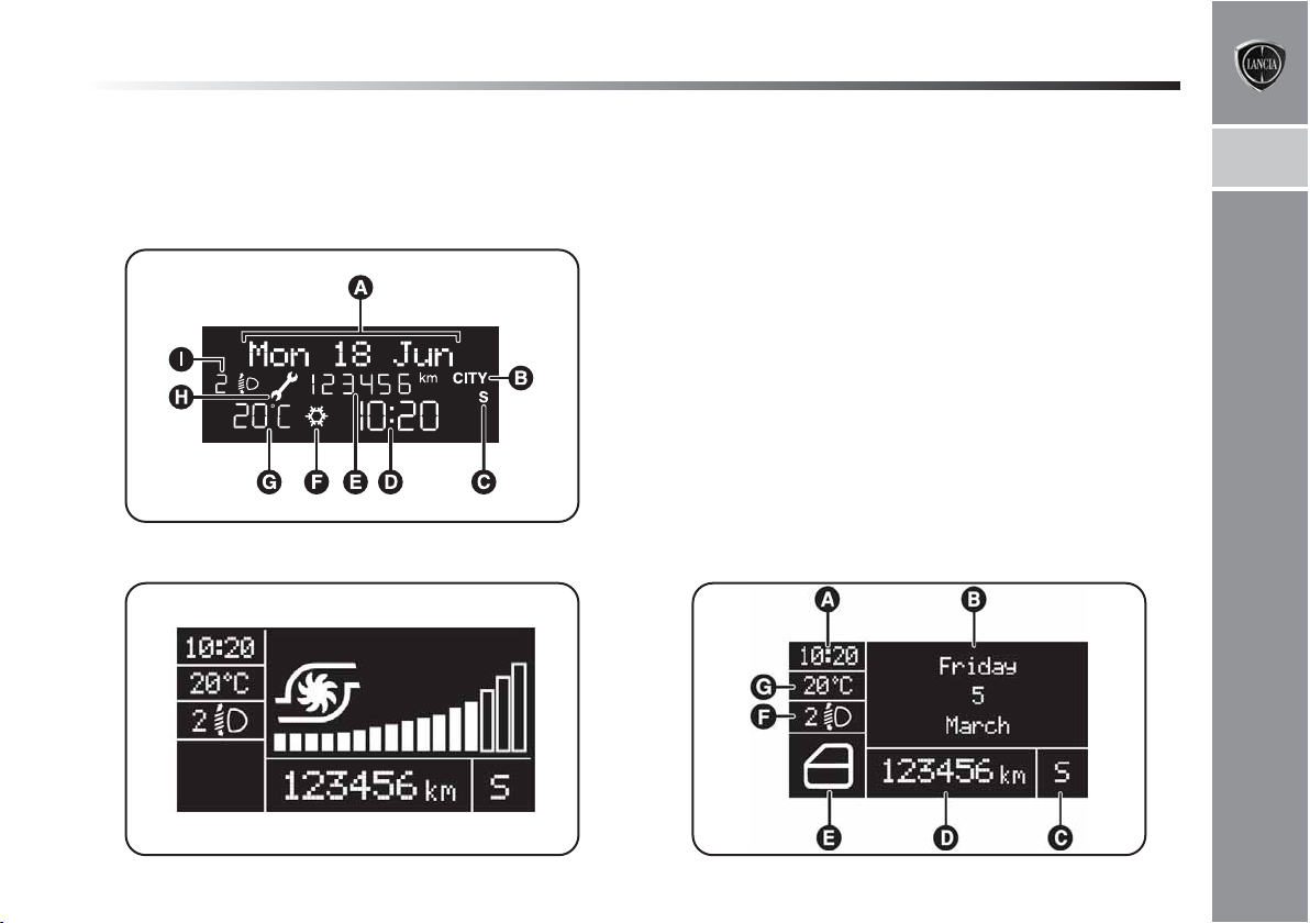
MULTIFUNCTIONAL DISPLAY “STANDARD”
SCREEN fig. 4
The standard screen shows the following information:
A. Date
B. Possible activation of Dualdrive electric power steering
C. Sport driving mode indication (where provided)
D. Time
E. Odometer (distance travelled in kilometres/miles)
F. Possible presence of ice on road
G. Outside temperature
H. Scheduled servicing deadline
I. Headlight alignment position (with dipped beam head-
lights on only).
Page 22
GETTING TO KNOW YOUR CAR
21
On some versions the display shows the turbine pressure
fig. 5 when the “engine info ” menu item is selected and
the key is turned to MAR.
fig. 4
L0E1000g
RECONFIGURABLE MULTIFUNCTIONAL
DISPLAY “STANDARD” SCREEN fig. 6
The standard screen shows the following information:
A. Time
B. Date
C. Sport driving mode indication (where provided)
D. Odometer (distance travelled in kilometres/miles)
E. Car status (e.g. doors open, ice on road, etc.)
F. Headlight alignment position (with dipped beam head-
lights on only).
G. Outside temperature
1
fig. 5
L0E0004m
fig. 6
L0E1001g
Page 23
22
GETTING TO KNOW YOUR CAR
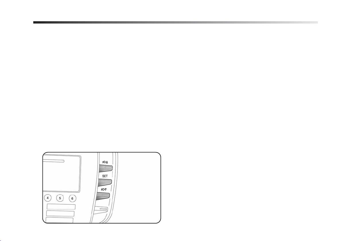
CONTROL BUTTONS Fig. 7
Õ
: to scroll up through the displayed menu and the re-
lated options or to increase the displayed value.
SET: press briefly to access the menu and/or go to next
screen or confirm the required menu option. Hold down
to go back to the standard screen.
Ô
: to scroll down through the displayed menu and the re-
lated options or to decrease the value displayed.
IMPORTANT Buttons ÕandÔactivate different functions according to the following situations:
– within the menu, they allow you to scroll up and down
through the options;
- when carrying out settings they allow you to increase
or decrease values.
IMPORTANT When one of the front doors is opened, the
display will turn on and show the clock and km or mi covered for a few seconds.
fig. 7
L0E0005m
Page 24

GETTING TO KNOW YOUR CAR
23
SETUP MENU
The menu comprises a series of items which can be selected using the
selection and setting operations (set-up) given in the following paragraphs. Some items also have a sub-menu. The
Set-up Menu is activated by briefly pressing the SET button.
The menu includes the following items:
– MENU
– LIGHTING
– SPEED BEEP
– HEADLIGHT SENSOR (where provided)
– CORNERING LIGHTS (where provided)
– TRIP B ACTIVATION/INFO
– TIME SETTING
– DATE SETTING
Õ
and Ôbuttons to access the different
– FIRST PAGE (where provided)
– SEE RADIO
– AUTOCLOSE
– UNITS OF MEASUREMENT
– LANGUAGE
– BUZZER VOLUME
– BUTTON VOLUME
– SEAT BELT BEEP/BUZZ.
– SERVICE
– AIR BAG/PASSENGER BAG
– DAYTIME LIGHTS
– EXIT MENU
1
Page 25

24
GETTING TO KNOW YOUR CAR
Selecting an option from the main menu
without submenu:
– briefly press the SET button to select the main menu option to be set.
– Press button
setting;
– briefly press the SET button to store the new setting and
to go back to the main menu option selected previously.
Selecting an option from the main menu with
submenu:
– briefly press the SET button to display the first submenu
option;
– press button Õor Ô(by single presses) to scroll through
all the submenu options;
– briefly press the SET button to select the displayed submenu option and to open the relevant set-up menu;
– press Õor Ô(by single presses) to select a new setting
for this submenu option;
– briefly press the SET button to store the new setting and
to go back to the previously selected submenu option.
Õ
or Ô(by single presses) to select a new
MENU ITEMS
Lighting (Adjusting lighting
inside the car)
This function may be used to set the brightness of the instrument panel, sound system controls and automatic climate control system controls (where provided) to 8 levels.
Proceed as follows to adjust the brightness:
– briefly press SET. The previously set level will flash on
the display;
Õ
– press
– briefly press SET to go back to the menu screen or hold
the button down to go back to the standard screen without storing the new settings.
Speed beep (Speed limit)
This function may be used to set the car speed limit (km/h
or mph); when this limit is exceeded the driver is immediately alerted (see “Instrument panel warning lights” in
chapter 1). To set the speed limit, proceed as follows:
– briefly press SET. The display will show a dedicated message;
or Ôto set the required brightness level;
Page 26

GETTING TO KNOW YOUR CAR
25
– press Õor Ôto switch the speed limit function “On” or
“Off”;
– if the function is On, press Õor Ôto select the required
speed limit and then press SET to confirm.
IMPORTANT The speed may be set in the range from 30
to 200 km/h, or from 20 to 125 mph according to the previously chosen unit of measurement (see “Setting the unit
of measurement”) described below. The setting will increase/decrease by five units each time button
pressed. Hold down button
setting rapidly. Complete the setting by briefly pressing
the button when you approach the required setting.
– briefly press SET to go back to the menu screen or hold
the button down to go back to the standard screen without storing the new settings.
To cancel the setting, proceed as follows:
– briefly press SET: ON flashes on the display;
– press Ô: Off flashes on the display;
Õ/Ô
to increase/decrease the
Õ/Ô
– briefly press SET to go back to the menu screen or hold
the button down to go back to the standard screen without storing the new settings.
Headlight sensor (Automatic headlight/dusk
sensor sensitivity adjustment) (where provided)
This function is used to adjust the dusk sensor sensitivity to three levels (level 1 = minimum, level 2 = medium,
level 3 = maximum); the higher the sensitivity, the lower
is
the amount of external light needed to switch the headlights on.
Proceed as follows to set:
– briefly press SET. The previously set level will flash on
the display;
– press Õor Ôto change the setting;
– briefly press SET to go back to the menu screen or hold
the button down to go back to the standard screen without storing the new settings.
1
Page 27

26
GETTING TO KNOW YOUR CAR
Cornering lights (activation/deactivation
“Cornering lights - Front fog lights with Cornering
function) (where provided)
This function allows you to activate/deactivate the Cornering lights. To activate/deactivate (ON/OFF) the lights,
proceed as follows:
– briefly press SET: “On” or “Off” will flash on the display (according to previous setting);
– press
– briefly press SET to go back to the menu screen or hold
the button down to go back to the standard screen without storing the new settings.
Trip B activation/info (Trip B on)
Through this option it is possible to activate (On) or deactivate (Off) the Trip B (partial trip) display.
For further information see “Trip computer”.
For activation / deactivation, proceed as follows:
– briefly press SET: (On) or (Off) will flash on the display
(according to previous setting);
– press Õor Ôto change the setting;
– briefly press SET to go back to the menu screen or hold
the button down to go back to the standard screen without storing the new settings.
Õ
or Ôto change the setting;
Time setting (Clock)
Using this function, it is possible to set the clock through
two sub-menus: “Time” and “Mode”.
Proceed as follows:
– briefly press SET: the display will show two sub-menus
“Time” and “Mode”;
– press Õor Ôto navigate the two sub-menus;
– once you have selected a sub-menu, press SET briefly;
– when accessing the “Time” submenu: briefly press SET:
“hours” will flash on the display;
– press Õor Ôto change the setting;
– briefly press SET: “minutes” will flash on the display;
– press Õor Ôto change the setting;
Page 28

GETTING TO KNOW YOUR CAR
27
IMPORTANT Each press of theÕor Ôbutton will increase/decrease the value by one unit. Hold the button
down to increase/decrease the setting rapidly. Complete
the setting by briefly pressing the button when you approach the required setting.
– when accessing the “Format” submenu: briefly press
SET: the previously set display format will flash on the
display;
– press Õor Ôto select “24h” or “12h”.
When you have made the required settings, briefly press
SET to go back to the sub-menu screen or hold the button down to go back to the main menu screen without storing the new settings.
– hold down SET to go back to the standard screen or
main menu, depending on which point in the menu you
have reached.
Date setting (Set Date)
Using this function it is possible to update the date (day
- month - year).
To update the date proceed as follows:
– briefly press SET: the year starts flashing on the display;
– press Õor Ôto change the setting;
– briefly press SET: “month” will flash on the display;
– press Õor Ôto change the setting;
– briefly press SET: “day” will flash on the display;
– press Õor Ôto change the setting.
IMPORTANT The setting increases or decreases by one
unit each time button Õor Ôis pressed. Hold the button down to increase/decrease the setting rapidly. Complete the setting by briefly pressing the button when you
approach the required setting.
– briefly press SET to go back to the menu screen or hold
the button down to go back to the standard screen without storing the new settings.
1
Page 29

28
GETTING TO KNOW YOUR CAR
First page (Display of information on the initial
screen) (where provided)
This function allows you to choose the information you
would like to see on the main screen. You can choose to
display the date or the turbo charger turbocharging pressure.
Proceed as follows:
– briefly press SET: “Initial page” will appear on the dis-
play;
– briefly press SET once again to show the display options:
“Date” and “Engine info”;
– press + or – to select the information you wish to see
on the main page of the display;
– briefly press SET to go back to the menu screen or hold
the button down to go back to the standard screen without storing the new settings.
When the key is turned to MAR and the initial check stage
is over, the display will show the information selected via
the “initial page” menu function.
See radio (Repeat audio information)
With this function the display repeats information relevant to the sound system.
– Radio: tuned radio station frequency or RDS message,
automatic tuning activation or AutoSTore;
– audio CD, MP3 CD: track number;
– CD Changer: CD number and track number.
To activate (On) or to deactivate (Off) sound system in-
fo displaying proceed as follows:
– press SET briefly: (On) or (Off) will flash on the display
(according to previous setting);
– press
– briefly press SET to go back to the menu screen or hold
the button down to go back to the standard screen without storing the new settings.
Autoclose (Automatic door lock operation with car
running)
When activated (On), this function automatically locks
the doors when the car speed exceeds 20 km/h.
Proceed as follows to switch this function on or off:
– briefly press SET to display a submenu;
– briefly press SET: (On) or (Off) will flash on the display
(according to previous setting);
– press
Õ
or Ôto change the setting;
Õ
or Ôto change the setting;
Page 30

GETTING TO KNOW YOUR CAR
29
– briefly press SET to go back to the submenu screen or
hold the button down to go back to the main menu screen
without storing the new settings;
– hold down SET to go back to the standard screen or
main menu, depending on which point in the menu you
have reached.
Unit of measurement (Set unit of measurement)
This function may be used to set the units of measurement
via three submenus: “Distances”, “Fuel consumption” and
“Temperature”. To set the required unit of measurement
proceed as follows:
– briefly press SET to display the three sub-menus;
– press
– once you have selected a sub-menu, press SET briefly;
Õ
or Ôto navigate the three sub-menus;
- when accessing the “Distance” submenu: briefly press
SET: either “km” or “mi” will appear on the display (according to the previous setting);
Õ
– press
– when accessing the “Fuel consumption” submenu:
briefly press SET: either “km/l ”, “l/100km” or “mpg”
will appear on the display (according to the previous setting);
If the set distance unit is “km”, the display enables setting of the fuel consumption unit (km/l or l/100) depending on the amount of fuel consumed.
If the distance unit of measurement is set as“mi” the fuel
consumption unit of measurement will be displayed in
“mpg”.
– press
– when accessing the “Temperature” submenu: briefly
press SET: either “°C” or “°F” will appear on the display
according to the previous setting;
– press Õor Ôto change the setting;
When you have made the required settings, briefly press
SET to go back to the sub-menu screen or hold the button down to go back to the main menu screen without storing the new settings.
– hold down SET to go back to the standard screen or
main menu, depending on which point in the menu you
have reached.
or Ôto change the setting;
Õ
or Ôto change the setting;
1
Page 31

30
GETTING TO KNOW YOUR CAR
Language (Selecting the language)
Messages can be displayed in the following languages: Italian, German, English, Spanish, French, Portuguese, Dutch.
To set the required language proceed as follows:
– briefly press button SET: the previously set language
starts flashing on the display;
– press
– briefly press SET to go back to the menu screen or hold
the button down to go back to the standard screen without storing the new settings.
Buzzer volume (Adjusting the failure/warning
buzzer volume)
With this function the volume of the buzzer accompanying
any failure/warning indication can be adjusted (8 levels).
To adjust the volume proceed as follows:
– briefly press SET: the previously set volume level starts
flashing on the display;
– press Õor Ôto change the setting;
– briefly press SET to go back to the menu screen or hold
the button down to go back to the standard screen without storing the new settings.
Õ
or Ôto change the setting;
Button volume (Button volume adjustment)
This function enables you to set the volume of the roger-beep
accompanying the activation of buttons SET, Õand Ô.
To adjust the volume proceed as follows:
– briefly press SET: the previously set volume level starts
flashing on the display;
– press Õor Ôto change the setting;
– briefly press SET to go back to the menu screen or hold
the button down to go back to the standard screen without storing the new settings.
Seat belt beep/buzz.
(Buzzer activation for S.B.R. indication)
This function can only be displayed after a Lancia Dealership has deactivated the S.B.R. system (see paragraph
“S.B.R. system” in chapter 2).
Service (Scheduled servicing)
This function allows you to view information on car servicing deadlines based on kilometres travelled.
Page 32

GETTING TO KNOW YOUR CAR
31
This information can be consulted as follows:
– briefly press SET: the display shows the next service
deadline in km or mi according to the previous setting (see
paragraph “Distance unit of measurement”);
– briefly press SET to go back to the menu screen or hold
the button down to go back to the standard screen.
IMPORTANT The “Scheduled Servicing Plan” requires
the vehicle to be serviced every 35,000 km (or equivalent distance is miles). This information is displayed automatically when the key is turned to MAR, from 2,000
km (or equivalent distance is miles) from the deadline,
and reappears every 200 km (or equivalent distance is
miles). The indications will appear more frequently when
there are less than 200 km left. The indication will appear
in kilometres or miles according to the unit of measurement settings. When the next scheduled service operation is approaching, the message “Service” will appear on
the display followed by the number of kilometres or miles
left when the key is turned to MAR. Go to a Lancia Dealership where the “Scheduled Service” operations will be
performed and the message will be reset.
Air Bag/Passenger Bag
This function is used to activate/deactivate the front passenger’s air bag.
Proceed as follows:
– briefly press SET and, after displaying the message “Bag
pass: Off) (to deactivate) or Bag pass: On) (to activate) by
pressing
– the confirmation request message will be displayed;
– press Õor Ôto select (Yes) (confirming activa-
tion/deactivation) or (No) (to abort);
– briefly press SET to confirm the setting and go back to
the menu screen or hold the button down to go back to the
standard screen without storing the new settings.
Õ
or Ô, press SET once again;
1
Page 33

32
GETTING TO KNOW YOUR CAR
Daytime lights (D.R.L. - Smart Daytime Light)
This function allows you to activate/deactivate the daylight lights.
Proceed as follows to switch this function on or off:
– briefly press SET to display a submenu;
– briefly press SET: (On) or (Off) will flash on the display
(according to previous setting);
– press + or – to change the setting;
– briefly press the SET button to go back to the submenu
screen or hold the button down to go back to the main
menu screen without storing the new settings;
– hold down SET to go back to the standard screen or
main menu, depending on which point in the menu you
have reached.
Exit Menu
This is the last function that closes the setting cycle listed in the initial menu screen. Briefly press SET to go back
to the standard screen without storing the new settings.
Press
Ô
to return to the first menu option (Speed Beep).
DISPLAY INDICATIONS
IMPORTANT Failure indications on the display fall into
one of two categories: serious faults and less serious faults.
Serious failures are indicated by a repeated and prolonged
warning cycle.
Less serious failures are indicated by a limited warning
cycle.
Press SET to stop the warning cycle in both cases. The
warning light (or symbol in the display) will remain on
until the cause of the malfunction is eliminated.
Luggage compartment not closed
R
closed correctly. The display will show a dedicated message.
S
correctly (red)
This symbol (where provided) lights up on the
display when the luggage compartment is not
Bonnet not closed correctly (red)
This symbol (where provided) lights up on the
display when the bonnet is not closed correct-
ly. The display will show a dedicated message.
Page 34

GETTING TO KNOW YOUR CAR
33
External lighting failure (amber)
W
?
up on the display to warn the driver of the possible presence of ice on the road.
The display will show a dedicated message.
e
The symbol lights up on the display when a
fault is detected in the brake lights.
The display will show a dedicated message
Possible presence of ice on the road
The outdoor temperature indication starts
flashing when the outside temperature reach-
es or falls below 3°C and the ?symbol lights
Lane assistance on
The display shows a dedicated message when
the lane assistance function is switched on.
Adaptive lighting not available
f
è
cia Dealership.
õ
Speed limit exceeded
The display shows a dedicated message when the preset
speed limit is exceeded (for Arabic countries the speed limit is set at 120 km/h). The icon shown on the display represents the set speed limit.
The display shows a dedicated message when the
adaptive lighting system is not available.
Contact a Lancia Dealership.
Steering corrector not available
(DST - Dynamic Steering Torque)
The display shows a dedicated message when
the steering corrector has failed. Contact a Lan-
Service deadline exceeded
The display shows a dedicated message to in-
dicate the scheduled servicing deadline.
1
Page 35

34
GETTING TO KNOW YOUR CAR
TRIP COMPUTER
GENERAL FEATURES
The Trip computer is used to display information on car
operation when the key is turned to MAR. This function
allows you to define two separate trips called “Trip A” and
“Trip B” for monitoring the car’s complete mission (trip)
in a mutually independent manner.
Both functions can be reset (reset - start of new mission).
Trip A can be used to display figures relating to:
– Range
– Distance travelled
– Average fuel consumption
– Instantaneous fuel consumption
– Average speed
– Travel time (driving time).
– Trip A Reset
The Trip B function is used to display information relating to:
– Distance travelled B
– Average fuel consumption B
– Average speed B
– Travel time B (driving time).
– Trip B Reset
Note “Trip B” functions may be excluded (see “Enabling
Trip B”). “Range” and “Instantaneous fuel consumption”
parameters cannot be reset.
Values displayed
Range
Approximately indicates the distance the vehicle can travel with the present amount of fuel in the tank. The message
“- - - -” will appear on the display in the following cases:
– range value lower than 50 km (or 30 mi)
– car left parked with the engine running for a long time.
IMPORTANT Changes in the range value can be affected by many factors: driving style (see “Driving style” in
“Starting up and driving”), type of route (motorway, urban cycle, mountain roads, etc…), conditions of use of the
car (load, tyre pressure, etc.). The above notes should
therefore be taken into consideration when planning a trip.
Distance travelled
This indicates the approximate distance covered from the
start of the new mission.
Page 36

GETTING TO KNOW YOUR CAR
35
Average fuel consumption
This value shows the approximate average fuel consumption from the start of the new mission.
Instantaneous fuel consumption
This indicates any change in fuel consumption. The value is
constantly updated. The message “- - - -” will appear on the
display if the car is parked with the engine running.
Average speed
This value shows the average speed of the car based on
the overall time elapsed since the start of the new mission.
Travel time
This value shows the time elapsed since the start of the
new mission.
Trip Reset
This resets the Trip computer settings
TRIP button fig. 8
The TRIP button is located on the right-hand lever. With
the ignition key turned to MAR, this button allows you
to view the previously described parameters and also zero them to begin a new mission:
– short press to display the different values;
– long press to reset and then start a new mission.
1
fig. 8
L0E0007m
Page 37

36
GETTING TO KNOW YOUR CAR
New mission
The new mission begins after:
– “manual” resetting by the user, by pressing the rele-
vant button;
– automatic resetting, when the Trip distance reaches
9999.9 km or when the Travel time reaches 99.59 (99
hours and 59 minutes);
– disconnection/reconnection of the battery.
IMPORTANT If the reset operation is carried out when
“Trip A” is being displayed, only the information associated with this function is reset.
IMPORTANT If the reset operation is carried out when
“Trip B” is being displayed, only the information associated with this function is reset.
Start trip procedure
With ignition key turned to MAR, carry out the reset operation by pressing and holding down the TRIP button for
longer than 2 seconds.
Exit Trip
You can automatically exit from the TRIP function once
all the values have been displayed or by holding the SET
button down for more than 1 second.
SYMBOLS
Special coloured labels have been attached near to or on
some of the components of your car. These labels bear
symbols that remind you of the precautions to be taken
with regards to that particular component.
A plate summarising these symbols can be found under
the bonnet.
Page 38

GETTING TO KNOW YOUR CAR
37
THE LANCIA CODE SYSTEM
This is an electrical engine locking system which increases
protection against an attempted theft of the car. It is automatically activated when the ignition key is extracted.
Each key contains an electronic device which modulates
the signal emitted during ignition by an antenna built into the ignition device. This signal is the ‘password’ which
changes at each ignition and which the control unit uses
to recognise the key and allow ignition.
OPERATION
Each time the car is started by turning the ignition key
to MAR, the Lancia CODE system control unit sends an
acknowledgement code to the engine control unit to deactivate the inhibitor.
The code is sent only if the control unit of the Lancia
CODE system has acknowledged the code received from
the key.
Each time the ignition key is turned to STOP, the Lancia
CODE system deactivates the functions of the electronic
engine control unit.
If the code is not recognised correctly during ignition, the
Y warning light (or symbol in the display) comes on.
In this case turn the key to STOP and then to MAR; if
the lock persists try again with the spare set of keys. Contact a Lancia Dealership if you still cannot start the engine.
IMPORTANT Each key has its own code which must be
stored by the system control unit. To have new keys memorised (up to a maximum number of eight keys), contact
a Lancia Dealership and be ready to present all the keys
you have at present, the CODE card, a personal identity
document and the car ownership documents. The codes
of any keys not presented during the memorising procedure will be deleted. This is to prevent lost or stolen keys
from starting the engine.
Y warning light (or symbol in the display) lit up
during driving
H If the Y warning light (or symbol in the display)
comes on, this means that the system is running a selfdiagnosis test (caused, for example, by a voltage drop).
H If the Y warning light (or symbol in the display) remains
on, contact a Lancia dealership.
The electronic components inside the key may
be damaged if the key is submitted to sharp
knocks.
1
Page 39

38
GETTING TO KNOW YOUR CAR
THE KEYS
CODE CARD (available on request for
versions/markets where provided)
A CODE card fig. 9 is provided together with the vehicle
keys. This should be presented to a Lancia Dealership
should you require any duplicate keys.
IMPORTANT In order to ensure complete efficiency of the
electronic devices inside the keys, they should never be exposed to direct sunlight.
The ignition key and the CODE card must be
handed over to the new owner when selling
the car.
MECHANICAL KEY (where provided)
The key is provided with a metal insert A-fig. 10, which
operates:
H the ignition switch;
H the door locks;
fig. 9
L0E0102m
fig. 10
L0E0103m
Page 40

GETTING TO KNOW YOUR CAR
39
KEY WITH REMOTE CONTROL fig. 11
The key is provided with a metal insert A, which operates:
H the ignition switch
H the door locks
To open/close the metal insert, press button B.
Button
In this case the timed lighting of interior courtesy lights
and double flashing of direction indicators (for versions/markets where provided) takes place.
Press button Ëfor longer than 2 seconds: to open the windows.
Button Áremotely locks the doors.
Ë
remotely releases the doors locks.
In this case the interior courtesy lights go out and the direction indicators flash once.
Á
Press button
dows.
If one or more door are open, the doors will not be locked.
Button
Tailgate opening is indicated by the double flashing of the
direction indicators; tailgate closing by single flashing (only with the alarm switched on, where provided).
Button B opens power-assisted opening of metal insert
A.
To reinsert the metal insert into the grip, hold down button B and turn the insert in the direction shown by the arrow until you hear it click into place. Then release button B.
R
opened for getting out of the car are released; the
tailgate remains locked. To realign the system the
locking/unlocking buttons Á/Ëmust be pressed once
again.
for longer than 2 seconds: to close the win-
can be used to open the tailgate remotely.
If the button for locking doors Áis accidentally pressed from the inside, only the doors
1
fig. 11
L0E0104m
Page 41

40
GETTING TO KNOW YOUR CAR
Press button B-fig. 11 only when the key is
far away from you, particularly from your
eyes and other objects that may be damaged
(e.g. clothing). Do not leave the key unattended, because someone, a child especially, may accidentally press the button while handling the key.
Requesting additional remote controls
The system acknowledges up to 8 remote controls. Should
a new remote control be necessary, contact a Lancia Dealership and be ready to present the CODE card, a personal identity document and the car’s ownership documents.
Replacing the battery of the key with remote
control fig. 12
Battery replacement:
H press button A and bring the metal insert B to the
“open” position;
H turn screw C to : using a small point screwdriver;
H take out the battery case D and replace the battery E,
respecting its polarity;
H refit the battery case D inside the key and lock it by
turning the screw C to Á.
Used batteries are harmful to the environment. They should be disposed of as specified
by law in special containers or taken to a
Lancia Dealership, which will take care of their disposal.
fig. 12
L0E0105m
Page 42

GETTING TO KNOW YOUR CAR
41
Replacing the remote control cover fig. 13
To replace the remote control cover, follow the procedure
shown in the diagram.
ALARM (where provided)
1
The alarm, which is provided in addition to the remote
control functions described previously, is controlled by a
receiver located under the dashboard, near the fuse box.
ALARM TRIPPING
The alarm trips in the following cases:
H when a door, the bonnet or the tailgate is opened ille-
gally (perimeter protection);
H when the ignition system is operated (ignition key ro-
tated to MAR);
H when the battery cables are cut;
H when someone is moving inside the passenger com-
partment (volume-sensing protection);
H when the vehicle is lifted or tilted.
According to the market, when the alarm is tripped this
operates the alarm siren and direction indicators (for approximately 26 seconds). Alarm tripping and the number
of cycles depend on the sales market.
There are a maximum number of acoustic/visual cycles.
When this is reached the system returns to normal operation.
The volume sensing and anti-tilt protection can be excluded by adjusting the dedicated control on the front
courtesy light (see “volume sensing/anti-tilt protection”).
fig. 13
L0E0106m
Page 43

42
GETTING TO KNOW YOUR CAR
IMPORTANT The engine inhibitor function is guaranteed
by the Lancia CODE, which is automatically activated
when the ignition key is extracted from the starter device.
SWITCHING ON THE ALARM
With the doors and bonnet closed and the ignition key
either turned to STOP or removed, point the key with the
remote control towards the vehicle and press and release
button
Excluding some versions for specific markets, the system
produces an acoustic warning (beep) and enables door
locking.
Before the alarm is enabled, a self-diagnosis test is run:
if a fault is detected, the system emits another sound warning and a message is shown on the display, (see “Instrument panel warning lights”).
In this case switch off the alarm by pressing Ë, check that
all the doors, bonnet and tailgate are closed correctly; then
switch the alarm back on by pressing Á.
If a door or the bonnet is not correctly closed, it will be excluded from the testing by the alarm system.
If the alarm produces an acoustic signal even when the
doors, bonnet and tailgate are correctly closed, a failure
has occurred in system operation. Contact a Lancia Dealership.
Á
.
IMPORTANT Centrally locking the doors using the metal insert on the key does not activate the alarm.
IMPORTANT Originally, the alarm is configured in compliance with the regulations existing in the different countries.
SWITCHING OFF THE ALARM
Press button Ëon the key with the remote control.
The following operations are performed (excluding some
versions for specific markets):
H the direction indicators flash twice;
H two brief acoustic signals are emitted (“BEEP”);
H the doors are unlocked.
IMPORTANT If the central door locking system is released using the metal insert of the key, the alarm is not
disabled.
Page 44

GETTING TO KNOW YOUR CAR
43
VOLUME SENSING/ANTI-TILT PROTECTION
To guarantee the correct operation of the protection, close
the side windows and sunroof completely (where provided).
If necessary this function can be excluded (e.g. when leaving pets on board) by pressing button A-fig. 14, located
on the front courtesy light, before activating the alarm.
When the function is disabled, this is indicated by the LED
on the button flashing for several seconds. Any disabling
of the volume sensing/anti-tilt protection must be repeated each time the instrument panel is switched off.
BREAK IN ATTEMPT INDICATION
Any break in attempt is indicated by the
(or symbol in the display) lighting up, together with a message shown on the display (see “Instrument panel warning lights”).
Y
warning light
DISABLING THE ALARM
To permanently disable the alarm (e.g. during a lengthy
period of idleness), simply lock the vehicle by turning the
metal insert of the key with remote control in the lock.
IMPORTANT If the battery of the key with the remote
control goes flat or the system fails, the alarm can be
switched off by placing the key in the ignition switch and
turning it to MAR.
1
fig. 14
L0E0153m
Page 45

44
GETTING TO KNOW YOUR CAR
IGNITION SWITCH
The key can be turned to 3 different positions fig. 15:
H STOP: the engine is off, the key can be extracted, the
steering is locked. Some electrical devices (e.g. car radio, central door locking system, etc.) are enabled
H MAR: driving position. All electrical devices are en-
abled
H AVV: engine start-up.
The ignition switch is fitted with an electronic safety sys-
tem that requires the ignition key to be turned back to
STOP if the engine will not start, before the starting operation can be repeated.
STEERING COLUMN LOCK
Engagement
When the key is at STOP, remove the key and turn the
steering wheel until it locks.
Disengagement
Move the steering wheel slightly as you turn the ignition
key to MAR.
IMPORTANT In some parking conditions (e.g.: wheels
turned) the effort required to move the steering wheel and
disengage the steering lock may be increased.
Never extract the key while the vehicle is
moving. The steering wheel would lock as
soon as the steering wheel is turned. This also applies to when the car is towed. Under no circumstances should after-market operations be carried out involving steering system or steering column modifications (e.g.: installation of anti-theft
device). This could negatively affect performance
and safety, invalidate the warranty and also result in vehicle non-compliance with type-approval
requirements.
fig. 15
L0E0107m
Page 46

GETTING TO KNOW YOUR CAR
SEATS
All adjustments made to front and rear seats
must only be carried out when the vehicle is
at a standstill.
After releasing the adjustment levers, always
check that the seat is locked on the runners
by trying to move it back and forth. If it is not
locked, the seat may move unexpectedly and make
you lose control of the car.
FRONT SEATS
Reach adjustment fig. 16
Lift lever A and push the seat forwards or backwards: your
arms should rest on the steering wheel rim while you are
driving.
45
1
Back rest angle adjustment fig. 16
Turn knob B.
fig. 16
L0E0008m
Page 47

46
GETTING TO KNOW YOUR CAR
Height adjustment fig. 16
Operate lever C to raise or lower the rear part of the seat
cushion to improve comfort.
Lumbar adjustment (driver’s seat) fig. 16
for lumbar adjustment, turn knob D.
ELECTRICALLY ADJUSTABLE FRONT SEATS
(where provided) fig. 17
Adjustment is possible when the ignition key is at MAR or
within 1 minute with ignition key at STOP or removed.
When opening one of the front doors, it is possible to adjust the seat on the side of the door opened for about 3
minutes or until closing the door.
Seat adjustment controls are the following:
Multifunction control A:
H to adjust height;
H to move seat backwards or forwards.
Multifunction control B:
H back rest angle adjustment;
H lumbar adjustment.
Seat warming (where provided) fig. 17
With ignition key at MAR, press buttons
C
to switch the
seat warming on/off.
The led on the button will light up when the function is
on.
fig. 17
L0E0009m
Page 48

GETTING TO KNOW YOUR CAR
47
REAR SEATS fig. 18
Adjusting backrest tilt
Lift lever A (one on each side) to adjust the tilting of the
left or right part of the backrest respectively (in order to
make the process easier, move the seat slightly forward using lever B).
Rear seats movement
The rear seats can be moved backwards and forwards (by
80 mm). To move the seats backwards or forwards operate levers B (one on each side).
When repositioning the rear backrest whilst
moving it, it is necessary to check that it is
correctly attached, grasping the backrest at
the top and shaking it.
1
fig. 18
L0E0010m
Page 49

48
GETTING TO KNOW YOUR CAR
HEAD RESTRAINTS
FRONT fig. 19
The height of the head restraints can be adjusted as follows.
H Upward adjustment: raise the head restraint until you
hear it click.
H Downward adjustment: press button A and lower the
head restraint.
Perform these operations only when the car
is stationary and the engine is not running.
The head restraints must be adjusted so that
they support your head and not your neck. Only then
do they fulfil their protective action. To optimise
head restraint protective action, adjust the backrest
upright and keep your head as close as possible to
the head restraint.
REAR (where provided) fig. 19
Headrests can be adjusted in height:
H To adjust upwards: Press button C and lift the head
restraint until the lock clicks.
H To adjust downwards: press button C and lower the
head restraint.
IMPORTANT Rear seat passengers should always set the
head restraints in “fully drawn out” position.
fig. 19
L0E0011m
Page 50

GETTING TO KNOW YOUR CAR
49
STEERING WHEEL
It can be adjusted vertically (and axially).
To adjust the steering wheel, move lever fig. 20 upwards
to position 1. Adjust the steering wheel into the most suitable position and lock it in this position by moving the
lever to position 2.
Perform these operations only when the car
is stationary and the engine is not running.
REARVIEW MIRRORS
1
INTERNAL REARVIEW MIRROR fig. 21
The mirror is fitted with a safety device that causes its
release in the event of a violent crash.
It can be moved using lever A to two different positions:
normal or antiglare.
ELECTROCHROMIC INTERNAL REARVIEW
MIRROR (where provided)
Some versions provide an electrochromic mirror with automatic antiglare function. An ON/OFF button in the lower area of the mirror enables/disables the electrochromic
function. When the function is activated this is indicated
by the LED on the mirror lighting up.
fig. 20
L0E0012m
fig. 21
L0E0013m
Page 51

50
GETTING TO KNOW YOUR CAR
Engaging reverse gear automatically sets the mirror for
daylight use.
DOOR MIRRORS fig. 22
Proceed as follows to adjust the position of the door mirrors:
H select the mirror using selector B;
H adjust the mirror using controls A, in all four direc-
tions.
Folding back door mirrors fig. 23
When required (for example when the mirror causes difficulty in narrow spaces) it is possible to fold the mirror
by moving it from position 1 (open), to position 2 (closed).
On some versions the door mirrors can be folded back electrically by operating a dedicated control.
When driving, the mirrors should always be
in position 1. As the door mirrors are curved,
they may slightly alter the perception of dis-
tance.
fig. 22
L0E0014m
fig. 23
L0E0015m
Page 52

CLIMATE COMFORT
GETTING TO KNOW YOUR CAR
51
1
fig. 24
VENTS fig. 24
1. Windscreen defrosting/demisting vents. – 2. Adjustable central vents – 3. Adjustable side vents – 4. Fixed vents for
side windows – 5. Lower vents – 6. Rear adjustable vent.
L0E0016m
Page 53

52
GETTING TO KNOW YOUR CAR
MANUAL CLIMATE CONTROL SYSTEM
fig. 25
CONTROLS fig. 25
A. Air temperature knob (red-hot / blue-cold)
B. Fan speed knob
C. Air distribution knob
μ toward the body and the side windows
∑ toward the body, the side windows and the feet
L0E0017m
∂ toward the feet only
∏ toward the feet and the windshield
- toward the windshield only.
Page 54

GETTING TO KNOW YOUR CAR
53
IMPORTANT It is advisable to activate air recirculation
in queues or in tunnels to prevent the introduction of polluted air. Do not use the function for a long time, particularly if there are many passengers on board, to prevent
the windows from misting up.
D Air recirculation on/off button
(LED lights when function is on).
E Manual climate control compressor on/off button (LED
lights when function is on).
F Heated rear windscreen on/off button.
When the function is active, an LED on the button is
lit. In order to maintain battery efficiency, the function
is automatically deactivated after about 20 minutes.
FAST FRONT WINDOW AND FRONT SIDE
WINDOWS DEMISTING/DEFROSTING
(MAX-DEF)
Proceed as follows:
H turn knob A to the red section;
H turn knob C to
H turn knob D to -;
H turn knob B to 4 - (maximum fan speed).
IMPORTANT The climate control system is very useful for
fast demisting because it dries the air. Adjust the controls
as described above and press knob B to switch the climate
control system on: the LED on the knob will light up.
LOOKING AFTER THE SYSTEM
Run the climate control system for at least 10 minutes
every month during the winter. Have the system inspected at a Lancia Dealership before the summer.
Ú;
1
Page 55

54
GETTING TO KNOW YOUR CAR
TWO-ZONE AUTOMATIC CLIMATE CONTROL SYSTEM (where provided)
fig. 26
The vehicle can be equipped with a two-zone automatic
climate control system, which regulates the passenger-side
air temperature separately from the driver side.
L0E0018m
The system is equipped with an AQS (Air Quality
System) function, which automatically switches on the air
recirculation system if the outside air is polluted (e.g. in
traffic queues and tunnels).
Page 56

GETTING TO KNOW YOUR CAR
55
SWITCHING ON THE CLIMATE CONTROL
SYSTEM
The system can be switched on by pressing any button;
it is, however, advisable to set the required temperature
on the display and then press the AUTO button.
The climate control system allows you to customise the
temperature (driver-side and passenger-side) with a maximum difference of 7°C.
The climate control system compressor only works with
the engine running and with an outdoor temperature of
above 4°C.
Automatic climate control operation (AUTO
function) A-fig. 26
Press AUTO; the system will automatically adjust:
H the amount of air introduced into the passenger com-
partment;
H the distribution of air inside the passenger compart-
ment;
cancelling any previous manual settings.
During climate control system automatic operation the
words FULL AUTO appear on the display.
During automatic operation it is still possible to adjust the
set temperature and carry out the following operations
manually:
H adjust fan speed;
H select air distribution;
H switch air recirculation and AQS function on/off;
H switch on the climate control system compressor.
It is advisable not to use the air recirculation function when the outside temperature
is low to prevent the windows from rapidly
misting up.
1
Page 57

56
GETTING TO KNOW YOUR CAR
Selecting air distribution B-fig. 26
Press one or more buttons
one of the 7 possible air distribution settings:
˙
Air flow to the windscreen and front side window
vents to demist/defrost them.
Air flow to the front and rear foot well vents. This
distribution setting rapidly heats the passenger
compartment.
Air flow distribution between front/rear vents,
˙
dashboard central/side vents, rear vent, wind-
screen and front side windows demisting vents.
Air flow distribution between foot well vents and
windscreen and front side window demisting/defrosting vents. This distribution setting allows adequate warming of the passenger compartment and prevents the windows from misting up.
Air flow distribution between foot well vents (hotter air) and central/side dashboard vents and rear
vent (cooler air).
/
/
˙ to manually select
˙ Air flow distribution between central/side dash-
board vents, rear vent and windscreen and front
side window demisting/defrosting vents. This distribution setting allows adequate ventilation of the
passenger compartment and prevents the windows
from misting up.
IMPORTANT For the climate control system to function,
one of the following buttons must be operated:
˙. The system does not allow all buttons
be switched off.
IMPORTANT Press OFF to restart the climate control system: in this way all previously stored operating conditions
are reset before switching off.
To restore automatic air distribution control after a manual selection, press AUTO.
/
/
/
˙ to
/
Page 58

GETTING TO KNOW YOUR CAR
57
Adjusting the fan speed fig. 26
Operate buttons C
fan.
The 12 possible speeds are indicated by bars lighting up
on the display:
H max fan speed = all bars lit
H min fan speed = one bar lit.
The fan can only be disabled (no bars lit) if the climate
control compressor has been switched off by pressing button ?.
To restore automatic fan speed control after a manual adjustment, press AUTO.
to increase/decrease the speed of the
p
Aligning the set temperatures
(MONO function) fig. 26
Press button D (MONO) to align the temperature between
the driver side and passenger side.
Then turn the AUTO or MONO knob to increase/decrease
the temperature between the two areas by the same
amount.
Press MONO again to deactivate the function.
Switching off the climate control system fig. 26
Press button E (OFF).
The following information is shown on the display:
H the word OFF;
H outdoor temperature indication;
H indication if air recirculation is switched on (LED on
button
T
lit).
1
Page 59

58
GETTING TO KNOW YOUR CAR
heated rear windscreen and door mirrors
demisting/defrosting fig. 26
Press button F (
function is active, an LED on the button lights up.
This function is timed and will turn off automatically after 20 minutes. Press (again to disable the function in
advance.
IMPORTANT Do not apply stickers on the inside of the
rear window over the heating filaments to avoid damage
that might cause it to stop working properly.
IMPORTANT Press
(in this case the LED on the button should be off).
(
) to activate the function: When the
to draw air in from the outside
T
Rapid window demisting/defrosting
(MAX-DEF function) fig. 26
Press button G -to automatically activate the timed operation of all the functions required to rapidly
demist/defrost the windscreen and front windows.
The functions are:
H climate control compressor engagement (with an out-
door temperature of above 4°C);
H disengagement (if previously engaged) of air recircu-
lation (the LED on button
H engagement of heated rear windscreen (the LED on
button -should be on) and door mirror heater coils;
H air temperature set to maximum;
H activation of air flow.
Activation of air recirculation and enablement of
AQS (Air Quality System) fig. 26
Press button
Air recirculation is carried out according to three possible operation modes:
H automatic control, indicated by the AQS appearing on
the display and the LED on button
T
.
should be off);
T
T
should be off;
Page 60

GETTING TO KNOW YOUR CAR
59
H forced disablement (air recirculation always off, air
drawn in from the outside), - the LED on button
should be off;
H forced engagement (air recirculation always on), the
LED on button
When OFF is pressed, the climate control system automatically activates air recirculation (the LED on button
should be on). It is still possible to activate outside
T
air recirculation (LED on the button is off) and vice versa, by pressing button
With the OFF button pressed (LED on the button is lit
up), it is not possible to enable the AQS (Air Quality System) function.
IMPORTANT The air recirculation system makes it possible to reach the required heating or cooling conditions
faster. Do not use the air recirculation function on
rainy/cold days as it would considerably increase the possibility of the windows misting up inside, especially if the
climate control system is not switched on. It is advisable
to switch internal air recirculation on while in queues or
in tunnels to prevent the introduction of polluted air. Do
not use the function for a long time, particularly if there
are many passengers on board, to prevent the windows
from misting up.
should be lit up.
T
T
.
T
Enabling the AQS (Air Quality System) function
The AQS function (AQS appears on the display), automatically activates internal air recirculation when the outside air is polluted (e.g. in traffic queues and tunnels).
IMPORTANT With the AQS function active, after 15 consecutive minutes of the internal air recirculation system
functioning, the climate control system enables the intake
of outdoor air for approximately 1 minute to freshen the
air in the passenger compartment. This takes place regardless of the pollution level of the outside air.
1
Page 61

60
GETTING TO KNOW YOUR CAR
Switching the climate control compressor
on/off I-fig. 26
Press button
compressor.
Compressor engagement
H the LED on button ?is lit up;
H Symbol ?is shown on the display.
Compressor disengagement
H the LED on button ?is off;
H symbol ?disappears from the display;
H internal air recirculation is excluded;
H the AQS function is disabled.
With the climate control system compressor disengaged,
it is not possible to introduce air of a lower temperature
than the outside temperature into the passenger compartment; in this case the symbol on the display will flash.
The disengagement of the climate control compressor remains in the system memory even after the engine has
been stopped. To engage the climate control compressor
press the button ?once again or press AUTO: in this last
case any manual settings will be cancelled.
to switch on the climate control system
?
EXTERNAL LIGHTS
The left-hand lever operates most of the external lights.
The external lights can only be switched on when the ignition key is on MAR. The instrument panel and the various controls on the dashboard will be illuminated when
the external lights are switched on.
DAYLIGHT lights (D.R.L. - Adaptive Daylight Led)
(where provided)
With the ignition key turned to MAR and the selector wheel
turned to position O the daylight lights are automatically activated; the other lights and internal illumination remain off. The automatic lighting up of the daytime lights
can be switched on/off using the display menus (see “Display” section in this chapter). If the daytime lights are
switched off, when the selector wheel is turned to O no
lights will come on.
fig. 27
L0E0019m
Page 62

GETTING TO KNOW YOUR CAR
61
The daytime lights are an alternative to the
dipped beam headlights for driving during
the daytime. They are compliant in countries
where is it obligatory to have lights on during the
day and permitted in those where it is not obligatory Daytime lights cannot replace dipped beam
headlights when driving at night or through tunnels.
The use of daytime lights is governed by the Highway Code of the country you are in. Keep to the
rules.
AUTOMATIC HEADLIGHT SENSOR
(dusk sensor) fig. 27 (where provided)
This sensor detects changes in external light levels according to the sensitivity of the setting: the higher the sensitivity, the lower the amount of external light needed to
switch the lights on. The sensitivity of the dusk sensor may
be adjusted, using the “Set-up menu” on the instrument
panel.
Activation
Turn the selector wheel to AUTO: in this way the external
lighting will switch on automatically according to the outside light level.
The headlights can only be flashed with the sensor on.
Deactivation
When the lights are switched off by the sensor, the dipped
beam headlights and side lights are switched off and the
daylight lights are switched on (if activated).
The sensor cannot detect the presence of fog: switch the
lights on manually in this case.
FRONT FOG LIGHTS WITH CORNERING LIGHTS
FUNCTION
When travelling at a speed of less than 40 km/h with the
dipped beam headlights on, when the steering wheel is
turned at a wide angle or the direction indicators are lit
up, a light (built into the front fog lights) will be activated on the side of the turn to increase night time visibility.
This function can be switched on/off using the display
menus (see “Display” section in this chapter).
1
Page 63

62
GETTING TO KNOW YOUR CAR
DIPPED BEAM HEADLIGHTS/SIDE LIGHTS
With the ignition key turned to MAR, turn the selector
wheel to 2. If dipped beam headlights are activated, the
daytime lights are switched off and the side lights, number plate light and dipped beam headlights are lit up. The
3
warning light will come on in the instrument panel.
When the ignition key is turned to STOP or removed, and
the selector wheel is turned from Oto 2, the number plate
light and side lights are lit. The 3warning light will
come on in the instrument panel.
Parking function
With the side lights on and the ignition key turned to STOP
or removed, it is possible to light up one side of the vehicle by moving the lighting lever down (left-hand side) or
up (right-hand side). In this case warning light 3on the
instrument panel will go out.
MAIN BEAM HEADLIGHTS
With the selector wheel in position 2, push the lever forward toward the dashboard (stable position). The 1 warning light will come on in the instrument panel. They are
switched off by pulling the lever towards the steering wheel.
Flashing the headlights
You can flash the headlights by pulling the lever towards
the wheel (unstable position). The 1 warning light on the
instrument panel will come on.
DIRECTION INDICATORS Fig. 28
Push the lever to (stable) position:
– up (position a): right-hand indicator ON;
– down (position b): left-hand indicator ON.
Warning light ¥or Îwill blink on the instrument pan-
el.. The direction indicators are switched off automatically
when the steering wheel is straightened.
fig. 28
L0E0020m
Page 64

GETTING TO KNOW YOUR CAR
63
LANE CHANGE FUNCTION
If you want to signal that you are changing lane, hold the
left-hand lever in the unstable position for less than half
a second. The direction indicator on the selected side flashes 5 times and then switches off automatically.
“FOLLOW ME HOME” DEVICE
This function allows the space in front of the car to be lit
up for a preset period of time.
Activation
With the ignition key on STOP or removed, pull the lever
towards the steering wheel within 2 minutes of switching
the engine off. The amount of time the lights remain on
is extended by 30 seconds at each movement of the lever,
up to a maximum of 210 seconds; after this the lights are
switched off automatically. Each time the lever is operated, the warning light on the instrument panel comes
on and the display shows how long the function will remain active. The warning light comes on the first time the
lever is operated, and stays on until the function is automatically deactivated. Each time you operate the lever, the
amount of time the lights will remain lit up increases.
Deactivation
Keep the lever pulled towards the steering wheel for more
than 2 seconds.
WINDOW WASHING
1
The right-hand lever fig. 29 controls windscreen
wiper/washer and heated rear window wiper/washer operation.
WINDSCREEN WIPER/WASHER fig. 29
This only operates with the ignition turned to MAR.
The right-hand lever can take five different positions:
A: windscreen wiper off.
B: intermittent operation;
With the lever in position B, turn selector wheel F to se-
lect one of four different speeds for the intermittent operation mode:
, = very slow intermittent operation
I = slow intermittent operation.
II = normal intermittent operation
III = fast intermittent operation.
C: continuous slow operation;
D: continuous fast operation;
E: temporary fast operation (unstable position).
Page 65

64
GETTING TO KNOW YOUR CAR
“Smart washing” function
Pull the lever towards the steering wheel (unstable position) to operate the windscreen washer jet. Keep the lever
pulled to activate both the windscreen washer jet and the
windscreen wiper with a single movement; the latter turns
on automatically if you keep the lever pulled for over half
a second. The windscreen wiper stops operating a few
strokes after the lever is released; after a few seconds, a
further cleaning stroke completes the wiping operation.
fig. 29
L0E0021m
REAR WINDOW WIPER/REAR WINDOW
WASHER
This only operates with the ignition turned to MAR.
Turn the selector wheel to
to operate the rear window
'
wiper.
With the windscreen wiper active, turn the selector wheel
to 'activate the rear window wiper which, in this case,
operates (in the different positions) in sync with the windscreen wipe but at half its rate. When reverse gear is engaged with windscreen wiper active, the rear window wiper
automatically turns on in slow continuous mode.
It stops when the reverse gear is disengaged.
Do not use the windscreen or rearscreen
wiper to remove layers of snow or ice from
the windscreen. In such conditions, the windscreen wiper may be subjected to excessive stress
and the motor protection which prevents operation
for a few seconds may trip. If the issue persists, contact a Lancia Dealership.
“Smart washing” function
Pushing the lever towards the dashboard (unstable position) will activate the rear window washer.
Keep the lever pushed to activate the rear window washer jet and the rear window wiper with a single movement;
the latter turns on automatically if you keep the lever
pushed for over half a second.
Page 66

GETTING TO KNOW YOUR CAR
65
The rear window wiper stops operating a few strokes after the lever is released; after a few seconds, a further
cleaning stroke completes the wiping operation.
RAIN SENSOR (where provided)
The rain sensor A-fig. 30 is located behind the interior
rear-view mirror in contact with the windscreen and automatically adjusts the frequency of the windscreen wiper
strokes according to the rain intensity during intermittent
operation.
The sensor has an adjustment range that varies progressively from wiper still (no stroke) when the windscreen
is dry, to wiper at first continuous speed (slow continuous operation) with intense rain.
Activation
Move the right lever down by one click.
The activation of the rain sensor is signalled by a command acquisition stroke.
IMPORTANT Keep the glass in the sensor area clean.
By turning selector wheel F-fig. 29 is it possible to increase
the sensitivity of the rain sensor to obtain a more rapid
variation between wiper still (no stroke) when the windscreen is dry, to wiper at first continuous speed (slow continuous operation).
The increase in the sensitivity of the rain sensor is signalled
by a control and acquisition “stroke”.
When the windscreen washer is operated with the rain sensor activated, the normal washing cycle is performed, at
the end of which the rain sensor resumes its normal automatic function.
1
fig. 30
L0E0023m
Page 67

66
GETTING TO KNOW YOUR CAR
Deactivation
Turn the ignition key to STOP.
The next time the vehicle is started (ignition key to MAR),
the sensor is not reactivated even if the lever is still in position B-fig. 29. To activate the sensor, move the lever to
position A or C and then back to position B.
Rain sensor activation is indicated by at least one wiper
stroke even if the windscreen is dry.
Do not activate the rain sensor when washing the car in an automatic car wash.
Make sure the device is switched off if there
is ice on the windscreen.
Make sure the device is switched off whenever the windscreen is being cleaned.
CRUISE CONTROL (constant speed
regulator) (where provided)
This is an electronically controlled driving aid, which allows you to drive at speeds of over 30 km/h on long and
straight dry roads (e.g.: motorways), at a constant speed,
without pressing the accelerator pedal.
It is not recommended for use on extra-urban roads with
traffic. Do not use it in town.
ENGAGING THE DEVICE
Turn selector wheel A-fig. 31 to ON.
The device may only be engaged in 4th or higher speeds.
fig. 31
L0E0022m
Page 68

GETTING TO KNOW YOUR CAR
67
When travelling downhill with the device engaged, the car
speed may exceed the memorised one.
The engagement of the device is signalled by the Ü warn-
ing light lighting up in the instrument panel (together with
a message shown on the display) (see “Instrument panel
warning lights” in chapter 1).
MEMORISING VEHICLE SPEED
Proceed as follows:
H turn selector wheel A-fig. 31 to ON and press the ac-
celerator until the vehicle reaches the desired speed;
H turn selector wheel B to (+) for at least three seconds
and then release it: the car speed will be memorised
and the accelerator pedal may be released.
If required (e.g. for overtaking), press the accelerator pedal to accelerate: the car will return to the previously set
speed when the pedal is released.
RESTORING MEMORISED SPEED
If the device has been disengaged, for example by pressing the brake or clutch pedal, the memorised speed can
be reset as follows:
H accelerate gradually until you reach a speed ap-
proaching the one memorised;
H engage the gear selected at the time of speed memo-
rising (4th, 5th or 6th gear);
H press button C-fig. 31.
INCREASING THE MEMORISED SPEED
This can be carried out in two ways:
H by pressing the accelerator and then memorising the
new speed reached;
or
H by temporarily turning selector wheel B-fig. 31 to (+).
Each movement of the selector wheel will correspond to
a slight increase in speed (about 1 km/h), while keeping
the selector wheel turned will correspond to a continuous
speed increase.
REDUCING THE MEMORISED SPEED
This can be carried out in two ways:
H by disengaging the device and then memorising the
new speed;
or
H by keeping selector wheel B-fig. 31 turned to (–) un-
til the new speed is reached; it will then be memorised
automatically.
Each movement of the selector wheel will correspond to
a slight reduction in speed (about 1 km/h), while keeping the selector wheel turned will correspond to a continuous reduction in speed.
1
Page 69

68
GETTING TO KNOW YOUR CAR
DISENGAGING THE DEVICE
Turn selector wheel A-fig. 31 to OFF or turn the ignition
key to STOP. In addition, the device is automatically disengaged in any of the following cases:
H when the brake or clutch pedal is pressed;
H if the ASR or Advanced ESP system cuts in (where pro-
vided);
When travelling with the device engaged, do
not set the gearshift lever to neutral.
In the event of a malfunction or fault, turn selector wheel A-fig. 31 to OFF and contact a
Lancia Dealership after having checked the
condition of the protective fuse.
COURTESY LIGHTS
FRONT COURTESY LIGHT WITH SPOT LIGHTS
fig. 32
Switch A- turns these lights on/off.
With switch A in the central position, lights C and D will
turn on/off when the front doors are opened/closed.
With switch A switched to the left, lights C and D will remain off. With switch A switched to the right, lights C and
D will remain on.
The lights turn on/off gradually.
Switch B performs the spot light function; with the light
off, it will turn on:
H light C if switched to the left;
H light D if switched to the right.
fig. 32
L0E0024m
Page 70

GETTING TO KNOW YOUR CAR
69
Environmental lights are provided as part of the courtesy light; these illuminate the vehicle when the dipped
beam headlights or side lights are switched on.
IMPORTANT Before getting out of the car, make sure that
both switches are in the central position: lights off with
doors closed in order to avoid draining the battery. In any
case, if the switch is left inadvertently in the On position,
the lights will turn off automatically 15 minutes after turning the engine off.
Courtesy light timing
To facilitate getting in/out of the car at night or with poor
lighting, 2 different timed switching on modes have been
provided.
Light timing when getting into the car
The courtesy lights will turn on as follows:
H for about 10 seconds when the front doors are un-
locked;
H for about 3 minutes when one of the side doors is
opened;
H for about 10 seconds when the doors are closed.
Timing is interrupted when the ignition key is turned to
MAR.
Light timing when getting out of the car
After removing the key from the ignition switch, the courtesy lights will turn on as follows:
H within 2 minutes of turning the engine off, for about
10 seconds;
H for about 3 minutes when one of the side doors is
opened;
H for about 10 seconds when one of the doors is closed.
H in the event of the fuel cut-off system cutting in, the
lights remain on for approximately 15 minutes, after
which they go out automatically.
The lights go out immediately when the doors are locked
(unless the fuel cut-off system has cut in.).
1
fig. 33
L0E0025m
Page 71

70
GETTING TO KNOW YOUR CAR
REAR COURTESY LIGHT fig. 33
Press the point indicated by the arrow to switch the lights
on/off (+ sign on the courtesy light lens cover).
The events that determine the lighting up of the front courtesy light also apply to the lighting up of the rear courtesy
light.
LUGGAGE COMPARTMENT LIGHT fig. 34
This light comes on automatically when the luggage compartment is opened and switches off when it is closed.
CONTROLS FOR
DUALDRIVE ELECTRIC POWER STEERING
SYSTEM fig. 35
Press button A to activate the “CITY” function (see “electric power steering system”). When the function is active, the message CITY is displayed on the instrument panel. Press the button once again to deactivate the function.
SPORT FUNCTION CONTROL (where provided)
fig. 35
Press button B: to activate the sports driving setting. This
is characterised by increased acceleration response and increased force required at the steering wheel to obtain a
more sporty drive.
fig. 34
L0E0026m
fig. 35
L0E0027m
Page 72

GETTING TO KNOW YOUR CAR
71
When this function is on (see“SPORT function”), the word
SPORT appears on the display. Press the button once again
to deactivate the function and return to the standard driving mode.
HAZARD WARNING LIGHTS fig. 36
These lights are switched on by pressing switch A, regardless of the position of the ignition key.
Warning lights
el when this device is activated.. To switch off the lights,
press button A once again.
Use of the hazard warning lights is governed by the Highway Code of the country you are in. Keep to the rules.
and¥are lit up on the instrument pan-
Î
Emergency braking
In the event of emergency braking the hazard warning
lights come on automatically, as do the
ing lights in the instrument panel.
The function switches off automatically when the nature
of the braking changes.
This function complies with current legislation.
and¥warn-
Î
1
fig. 36
L0E0028m
Page 73

72
GETTING TO KNOW YOUR CAR
FRONT FOG LIGHTS fig. 37
Press button A to activate the front fog lights. When the
front fog lights are activated the
5
warning light is lit
up on the instrument panel.
The front fog lights can be activated when the dipped
beam headlights are on.
REAR FOG LIGHTS fig. 37
When the dipped beam headlights are on, these can be activated by pressing button D.
With the lights on, the
4
warning light in the instrument
panel will come on at the same time. Press the button again
to turn the lights off.
AFS ADAPTIVE LIGHTS
(Adaptive Xenon Lights) fig. 38
The adaptive lights (see “Headlights” in this chapter) are
activated automatically when the vehicle is started. In this
situation the LED (amber) on button A will remain off.
Press button A to deactivate the adaptive lights (if activated); the LED on button A will light up. To reactivate
the adaptive lights: press button A once again (LED on
button is off).
In the event of a system failure, this is indicated on the instrument panel by the flashing of warning light for the
symbol appearing on the display along with a dedicat-
f
ed message (where provided).
fig. 37
L0E0029m
fig. 38
L0E0030m
Page 74

GETTING TO KNOW YOUR CAR
73
FUEL CUT-OFF SYSTEM
This system intervenes in the event of a collision, activating:
H cut off of fuel supply with resultant engine shut down;
H automatic door lock release;
H activation of all lights inside the car.
When the system has been triggered, the message “Fuel
cut off, see handbook” is displayed.
Carefully check the car for fuel leaks, for instance in the
engine compartment, under the car or near the tank area.
Following a collision, turn the ignition key to STOP to
avoid draining the battery.
To reset car operation, follow this procedure:
H turn the ignition key to MAR;
H activate the right-hand indicator;
H deactivate the right-hand indicator;
H activate the left-hand indicator;
H deactivate the left-hand indicator;
H activate the right-hand indicator;
H deactivate the right-hand indicator;
H activate the left-hand indicator;
H deactivate the left-hand indicator;
H turn the ignition key to STOP.
If, after a crash, you smell fuel or notice leaks
from the fuel system, do not reset the system
to avoid fire risk.
1
Page 75

74
GETTING TO KNOW YOUR CAR
INTERIOR FITTINGS
SUN VISORS fig. 39
These are arranged at the sides of the internal rearview
mirror.
They may be positioned frontally and to the side.
A mirror is provided on the back of the sun visors. This
is illuminated by courtesy light A. The driver and passenger-side sun visors also feature a document holder.
FRONT ARMREST WITH ODDMENT
COMPARTMENT
This is located between the front seats. An oddment compartment and cooled drinks compartment is located inside the armrest (see following sections). The armrest can
be moved backwards and forwards by operating cover
A-fig. 40.
Oddment compartment
Lift up cover A-fig. 40: you can then access oddment compartment B-fig. 40.
fig. 39
L0E0032m
fig. 40
L0E0033m
Page 76

GETTING TO KNOW YOUR CAR
Cooled drinks compartment
Press button A-fig. 41 and lift up armrest B: you can then
access cooled drinks compartment fig. 41.
IMPORTANT The compartment is designed to maintain
the temperature of the drinks placed inside it, which
should be chilled or heated before being placed in the compartment. The drinks will remain hot if the heater is
switched on or cool if the air conditioning compressor is
switched on.
75
1
fig. 41
L0E0034m
Page 77

76
GETTING TO KNOW YOUR CAR
REAR ARMREST (where provided)
To use armrest A-fig. 42, lower it as shown in the diagram
(for this procedure the central head restraint needs to be
lifted to the highest position).
Two compartments B are provided in the armrest
These can be used to hold cups and/or cans.
To use these, pull tab C in the direction shown by the arrow.
These is also an oddment compartment provided in the
armrest; this can be accessed by raising the flap.
fig. 42
L0E0035m
Page 78

GETTING TO KNOW YOUR CAR
77
GLOVE COMPARTMENT
To open the glove compartment, operate handle A-fig. 43.
When the glove compartment is opened, an internal courtesy light comes on. With the ignition key turned to STOP
this light remains on for 15 minutes.
If, during this period, a door or the tailgate is opened,
the 15 minute timing is reset.
Do not travel with the glove compartment
open: it could hurt the passenger in the event
of a crash.
CUP/BOTTLE HOLDERS fig. 46
The central tunnel has two cup/bottle holders.
1
fig. 43
L0E0037m
fig. 45
L0E0038m
Page 79

78
GETTING TO KNOW YOUR CAR
POWER SOCKET (12V) (where provided)
Power socket A-fig. 46 is located on the central tunnel and
is only operational when the ignition key is turned to MAR.
If the smoker’s kit is requested, the power socket is replaced with a cigar lighter.
On some versions an additional power socket B-fig. 46 is
provided in the luggage compartment.
Accessories with a maximum power of 180W
(maximum current uptake 15A) can be connected to the outlet.
CIGAR LIGHTER (where provided)
This is located on the central tunnel.
To activate the cigar lighter, press button A-fig. 47 with
the ignition key turned to MAR.
After a few seconds the button goes back to its initial position, and the cigar lighter is ready for use.
IMPORTANT Always check that the cigar lighter has
turned off.
IMPORTANT The cigar lighter becomes very hot. Handle
with care. The device must not be used by children: risk
of fire and/or burns.
fig. 46
L0E0039m
fig. 47
L0E0040m
Page 80

GETTING TO KNOW YOUR CAR
79
ASHTRAY
The ashtray is a removable plastic box fig. 48 with spring
loaded opening that can be fitted into the glass/can holder on the central tunnel.
IMPORTANT Do not use the ashtray as a paper bin: paper may catch fire upon contact with cigarette butts.
SUNROOF (where provided)
1
The large electric sunroof comprises two panes of glass;
the front one is mobile and the rear one fixed. These are
equipped with two sun blinds (front and rear) that can be
moved manually. With the sunroof closed, the blinds can
be placed in any position. To open the blinds: grip handle C-fig. 49, and move the blind to the required position by following the direction of movement shown by the
arrow. To close it, repeat the same operation in the opposite direction. The sunroof can only be operated when
the ignition key is on MAR. Controls A-B fig. 49 on the
front courtesy light panel control sunroof opening/closing.
To open
Press and hold down button B-fig. 49. The front glass panel will move into the spoiler position; press button B once
again and hold down for more than half a second to automatically move the sunroof to an intermediate position
(“Comfort” position). Pressing the opening control once
again and holding it down for more than half a second will
move the sunroof automatically to the end of travel; the sunroof glass can be stopped at any time in an intermediate
position by pressing the button once again.
IMPORTANT During the sunroof opening operation, the
blind will follow the movement of the sunroof.
fig. 48
L0E0041m
Page 81

80
GETTING TO KNOW YOUR CAR
To close
When the sunroof is in the fully opened position, press
button A-fig. 49; if the button is held down for more than
half a second, the front sunroof glass will automatically
move to the intermediate position (“Comfort” position).
If the button is pressed once again and held down for more
than half a second the sunroof will move to the spoiler position. Pressing the close button once again will completely close the sunroof.
fig. 49
L0E0108m
IMPORTANT During the sunroof closing manoeuvre the sun
blind will remain in the “fully open” position. If you would
like to close it, this must be done manually.
If transverse roof racks are fitted use the sunroof only in the “spoiler” position. Do not open
the sunroof in the presence of snow or ice: it
may be damaged.
When leaving the car, always remove the key
from the ignition device to avoid the risk of
injury due to accidental operation of the sunroof; it presents a risk to those left on board: incorrect use of the sunroof can be dangerous. Before
operation, always check that no-one is at risk of being injured by the moving sunroof or by objects getting caught and dragged by it.
Anti-pinch device
The sunroof is fitted with an anti-pinch safety system that
detects the presence of an obstacle during sunroof closing travel and cuts in by stopping and reversing the sunroof travel.
Page 82

GETTING TO KNOW YOUR CAR
81
INITIALISATION PROCEDURE
The sunroof must be re-initialised after disconnecting the
battery or if the relevant protection fuse is blown.
Proceed as follows:
H press button A-fig. 49 until the sunroof is completely
closed. Release the button;
H press and hold down button A for at least 10 seconds
and/or until the glass panel moves forwards by one
click. Release the button at this point;
H within 5 seconds of the previous operation, press and
hold down button A: The glass panel will carry out a
complete opening and closing cycle. Only release the
button when this cycle is complete.
EMERGENCY OPERATION
If the switch does not work, the sunroof can be operated
manually as follows:
H remove protective cap A-fig. 50 on the rear part of
the internal cover;
H take the Allen key provided from the container with
the on-board documentation or from the luggage compartment (versions with Fix&Go automatic);
H fit the key into seat B and turn it:
– clockwise to open the sunroof;
– counter-clockwise to close the sunroof.
1
fig. 50
L0E0109m
Page 83

82
GETTING TO KNOW YOUR CAR
DOORS
LOCK/RELEASE FROM OUTSIDE fig. 51
Unlocking the doors
To unlock all the doors: turn the key to position 1. Pull up
the associated handle to open the door. Press button Ë
on the remote control to unlock the doors.
Before opening a door, ensure that it is safe
to do so. Open the doors only when the car
is stationary.
Locking the doors
To lock all the doors: Turn the key to position 2 with all
the doors closed correctly.
Press button Á on the remote control to lock the doors. If
one of the doors is not fully closed, simultaneous locking
is disabled.
IMPORTANT If one of the doors is not closed correctly
or there is a fault in the system, the central locking system will not engage. If the manoeuvre is repeated 10/11
times in quick succession, the device is excluded for approximately 30 seconds.
fig. 51
L0E0042m
Page 84

GETTING TO KNOW YOUR CAR
83
LOCK/RELEASE FROM INSIDE fig. 52
From inside the vehicle (with the doors closed) press the
door locking/unlocking button A on the dashboard. If the
electrical system has failed, it is still possible to lock the
doors manually.
CHILD LOCK SYSTEM B-fig. 53
This system prevents the rear doors from being opened
from the inside.
This device can only be engaged with rear doors open:
H position 1 - device engaged (door locked);
H position 2 - device not engaged (door may be opened
from the inside).
The device stays on even if the doors are unlocked by the
central locking system.
IMPORTANT The rear doors cannot be opened from the
inside when the child-lock system is engaged.
Always use this device when carrying children.
After engaging the child lock on both rear
doors, check it is properly engaged by trying to open a rear door using the internal
handle.
1
fig. 52
L0E0043m
Page 85

84
GETTING TO KNOW YOUR CAR
EMERGENCY REAR DOOR LOCKING
DEVICE A-fig. 53
The rear doors are fitted with an emergency device that
allows the doors to be locked when there is no current.
Proceed as follows:
H insert the metal insert on the ignition key into housing
A;
H turn the key clockwise and then remove it from hous-
ing A.
The door lock knob can be realigned (only when the battery charge has been restored) as follows:
H press button
H press door locking/unlocking button
board;
H open a front door by inserting the key into the key
pawl;
H operate the internal door handle.
Ë
on the key;
≈
on the dash-
fig. 53
L0E0044m
Page 86

GETTING TO KNOW YOUR CAR
85
If the child lock was engaged and the previously described locking procedure carried
out, operating the internal handle will not
open the door but will only realign the door lock
knob. To open the door, the outside handle must be
used. The door central locking/unlocking button
≈
is not disabled by the engagement of the emer-
gency lock.
IMPORTANT If the battery is disconnected or the protection fuse blows, the door opening/closing mechanism
must be reinitialised as follows:
H close all the doors;
H press button Áon the key or door locking/unlocking
button
H press button Ëon the key or door locking/unlocking
button
≈
on the dashboard;
≈
on the dashboard.
ELECTRIC WINDOWS
1
These operate when the ignition key is turned to MAR and
for about 2 minutes after turning the key to STOP or removing it.
The control buttons are located in the door panels (the
driver-side door panel can be used to operate all the windows).
There is may be anti-crush safety device which starts
working when the front windows are closing.
CONTROLS fig. 54
A. opening/closing left-hand front window; “continuous
automatic” operation during window opening/closing
stage;
B. opening/closing right-hand front window; continu-
ous automatic operation during window opening/closing stage;
C. enabling/disabling of rear door electric window con-
trols;
D. opening/closing left-hand rear window (where pro-
vided); continuous automatic operation during window opening/closing stage;
E. opening/closing right-hand rear window (where pro-
vided); “continuous automatic” operation during window opening/closing stage.
Page 87

86
GETTING TO KNOW YOUR CAR
Press the buttons to open/close the required window.
When one of the two buttons is pressed briefly the window travel takes place in stages; if the button is held
down, continuous automatic operation is activated both
for closing and opening. . If the button is pressed once
again the window will stop in its current position.
Holding the button pressed for a few seconds will automatically raise or lower the window (only with key on
MAR).
Incorrect use of the electric windows may be
dangerous. Before and during operation en-
sure that passengers are not at risk from the
moving glass, either directly or through personal
objects getting caught in the mechanism.
Always remove the ignition key when leav-
ing the car to prevent the electric windows be-
ing operated accidentally and constituting a
danger to the passengers in the car.
Passenger-side front door/rear doors
On the passenger-side front door control panel, and on
some versions also on the rear doors, buttons F-fig. 54 are
provided to control the associated windows
fig. 54
L0E0045m
Page 88

GETTING TO KNOW YOUR CAR
87
Anti-pinch safety device
The vehicle is equipped with an anti-pinch safety device
for the upwards motion of the windows.
This safety system is capable of recognizing the presence
of an obstacle whilst the window is closing; when this happens, the system stops the travel of the glass and, depending on the position of the window, reverses its movement.
This device is also useful when the windows are activated accidentally by children on board the vehicle.
The anti-pinch function is active both during manual and
automatic operation of the electric windows. Following
the intervention of the anti-pinch system, the window travel is immediately interrupted and subsequently reversed
until the lower end of travel is reached. During this time
the window cannot be operated in any way.
IMPORTANT If the anti-pinch protection intervenes 5
times consecutively within 1 minute or a system failure
is detected, the automatic window closing function is inhibited. The window can then only be operated in steps of
half a second and the button must be released following
each step.
One of the following manoeuvres must be carried out in
order to restore correct operation:
H switch off and restart the engine;
H fully lower the window concerned.
IMPORTANT With ignition key at STOP or removed, the
electric windows remain active for about 3 minutes and
are deactivated the moment a door is opened.
1
Page 89

88
GETTING TO KNOW YOUR CAR
Electric window system initialisation
The safety system must be re-initialised after disconnecting the battery or if the relevant protection fuse is blown.
Initialisation procedure:
H fully close the window to be initialised manually;
H after the window has reached the upper end of travel,
hold the up button pressed for at least one second.
IMPORTANT Where provided, following the disconnection of the power supply (replacing or disconnecting the
battery or replacing the protection fuse for the electric windows control units), the automatic setting for the electric
windows must be reset.
The reset operation should be carried out with the doors
closed according to the following procedure:
1. completely lower the driver-side window and keep the
button pressed for at least 3 seconds once the end of
travel position has been reached;
2. completely raise the driver-side window and keep the
button pressed for at least 3 seconds once the end of
travel position has been reached;
3. repeat stages 1 and 2 for the passenger-side window
4. check that the initialisation has taken place correctly
by checking the automatic operation of the windows.
IMPORTANT With central locking on, operating the internal handle of one of the doors will unlock all the doors.
If there is no power (blown fuse, battery disconnected,
etc.) the doors can still be locked manually. As in this case
the automatic window opening function is not available,
to open or close the door with the window closed, apply
pressure to the window towards the vehicle interior, to aid
the passage of the window against the trim.
Page 90

GETTING TO KNOW YOUR CAR
89
LUGGAGE COMPARTMENT
OPENING THE TAILGATE
When unlocked, the tailgate can be opened from the outside by operating the handle fig. 55.
The tailgate can be opened at any time if car doors are unlocked.
The key with remote control should be used to open the
tailgate.
If the luggage compartment is not closed correctly, this is
indicated by the ´warning light coming on in the instrument panel or the Ricon appearing on the display
together with a dedicated message (see “Instrument panel warning lights” in this chapter).
Opening the tailgate turns the luggage compartment light
on: the light automatically turns off after you close the
tailgate.
The light remains on for about 15 minutes after the key
is turned to STOP: if, during this period, a door or the tailgate is opened, the 15 minute timing is reset.
Open the tailgate using the key with remote control
To release the tailgate lock press R. Luggage compartment opening is indicated by the double flashing of the
direction indicators; tailgate closing is indicated by single flashing (only with the alarm switched on, where provided).
1
fig. 55
L0E0046m
Page 91

90
GETTING TO KNOW YOUR CAR
CLOSING THE TAILGATE fig. 56
To close, lower the tailgate and press down near the lock
until you hear it click. There are handles (B) provided
inside the tailgate to allow it to be closed more easily.
Never exceed the maximum allowed load in
the luggage compartment; see chapter 6.
Make sure that the objects are arranged carefully in the luggage compartment so that they will
not be projected forwards following sudden braking. Do not travel with the tailgate open: exhaust
fumes could be introduced into the passenger compartment.
If you travel in areas with few filling stations
and you want to transport fuel in a spare
tank, respect the applicable laws, using only an approved, suitably secured tank. In the event
of a collision the fire risk is increased all the same.
Take care not to knock objects on the roof rack when
opening the tailgate.
fig. 56
L0E0047m
Page 92

GETTING TO KNOW YOUR CAR
91
OPENING THE TAILGATE IN AN EMERGENCY
fig. 57
To open the tailgate from the passenger compartment if the
car battery is flat or the electric tailgate lock is faulty, proceed as follows (see “Extending the boot” in this chapter)
H remove the rear head restraints;
H tilt the backrests;
H operate lever A to unlock the tailgate mechanically from
inside the luggage compartment.
EXTENDING THE LUGGAGE COMPARTMENT
The luggage compartment can be partially (1/3 or 2/3)
or totally extended by splitting the rear seat fig. 59.
Proceed as follows to extend the luggage compartment:
H completely lower the rear seat head restraints;
H move the seat belt to the side, making sure that it is
correctly extended and not twisted;
H release the parcel shelf blind (where provided) from
the backrests;
H operate one of the levers A-fig. 58 to fold back the re-
quired backrest (to make this procedure easier, move
the seat slightly forward using lever B);
1
fig. 57
L0E0048m
fig. 58
L0E0049m
Page 93

92
GETTING TO KNOW YOUR CAR
To further extend the luggage compartment, the rear seats
can be pushed forwards by operating handle B-fig. 58.
IMPORTANT In order to achieve a uniformly flat load
platform, the head restraints should be placed in the fully extended position before the seats are folded back.
REPOSITIONING THE REAR SEAT
To facilitate the backrest repositioning manoeuvre, it is
helpful to bring the seat cushion completely forward before folding back the seats.
Move the seat belts to the side, making sure that they are
correctly extended and not twisted. Press levers A (fig. 58),
lift up the backrests and push them backwards until you
hear a click from both attachment mechanisms.
Use handle B (fig. 58) to move the seats back until you
hear a click.
Make sure the backrest is properly secured
at both sides to prevent it moving forward in
the event of sharp braking, causing injury to
passengers.
fig. 59
L0E0110m
Page 94

GETTING TO KNOW YOUR CAR
93
REAR PARCEL SHELF
To remove the rear parcel shelf:
H release the attachments from the rear seat backrests
fig. 60;
H roll the rear parcel shelf blind back into the reel;
H release attachments A-fig. 61 (one on each side);
H release attachments B-fig. 61, rotate the rear parcel
shelf through 90° and slide it out.
To refit the rear parcel shelf, reverse the removal instructions.
1
fig. 60
L0E0050m
fig. 61
L0E0051m
Page 95

94
GETTING TO KNOW YOUR CAR
DOUBLE LOAD COMPARTMENT
(MAGIC BACK BOX) (where applicable)
In addition to reclining seats the car can also be equipped
with an adjustable load platform with two different heights
in order to even the load and adjust the luggage compartment capacity.
Keeping the load platform in the upper position makes it
possible for the space created underneath to be used as
another compartment that can be used to store more fragile or smaller objects.
To access the compartment under the load compartment,
lift up shelf A holding it with your hands and put the desired objects inside.
IMPORTANT Movements of the load platform may take
place if it is in a central position in relation to the luggage compartment.
fig. 62
L0E0220m
To place shelf A at the level of the floor
(fully lowered) fig. 63:
H always turn the elements C - Fig. 62 so that they are
always turn the elements C - Fig. 62 so that they are
in a vertical position against the seat backrest;
H grip the handle B and lift up shelf A by around 45°
(point 1);
H pull the shelf in a horizontal direction towards itself
until the end of travel position (point 2);
H push the shelf downwards gently until point 3 is rea-
ched (fully lowered);
H accompany the shelf to the “fully lowered” position
(point 4).
To move shelf A from the fully lowered position to
the highest position Fig. 64:
H pull handle B from point 1 and raise shelf A by around
45°;
H pull the shelf upwards to point 2 and leave it resting
on the side supports D;
H pull the shelf towards itself as far as point 3 (fully
forwards);
H let the shelf fall at point 4 in the "fully raised" position.
To extract the spare wheel:
H pull the load shelf upwards using handle B;
H lift up the load compartment carpet;
H extract the tape and hook for the carpet and attach it
to the boot upper seal.
Page 96

GETTING TO KNOW YOUR CAR
95
1
fig. 63
L0E0221m
Page 97

96
GETTING TO KNOW YOUR CAR
fig. 64
L0E0222m
Page 98

GETTING TO KNOW YOUR CAR
BONNET
OPENING fig. 65
Proceed as follows:
H pull lever A in the direction indicated by the arrow;
H operate lever B as shown in the diagram;
H lift the bonnet and at the same time release support
rod C from its catch, then insert the end of the rod into seat D in the bonnet (larger hole) and push to safety position (smaller hole), as shown in the diagram.
Incorrect positioning of the support rod may
cause the bonnet to drop suddenly. Perform these
operations when the car is stationary only.
Before lifting the bonnet, ensure that the
wiper arm is not lifted from the windscreen.
97
1
fig. 65
L0E0053m
Page 99

98
GETTING TO KNOW YOUR CAR
With the engine hot, work with caution inside
the engine compartment to avoid burns. Do
not place your hands near the fan: it may
switch on even if the ignition key has been removed.
Wait for engine cooling.
Pay attention to scarves, ties and other loose
fitting garments. If they accidentally touch
moving parts, they may get dragged in, posing serious risk to the wearer.
To close fig. 65
Proceed as follows:
H hold the bonnet up with one hand and with the other
remove rod C from seat D and fit it back into its catch;
H Lower the bonnet to approximately 20 centimetres
above the engine compartment and let it drop. Make
sure that the bonnet is completely closed and not only fastened by the safety catch by trying to open it. If
it is not fully closed, open the bonnet and repeat the
procedure. Do not simply press it.
For safety reasons, the bonnet must always
be fully closed while travelling. Make sure
that the bonnet is perfectly closed and that
the lock is engaged. If you discover that the bonnet
is not perfectly closed while travelling, stop immediately and close the bonnet in the correct manner.
Page 100

GETTING TO KNOW YOUR CAR
99
ROOF RACK/SKI RACK
FASTENERS
The attachments are located in the areas illustrated in
fig. 66 and can only be reached with the doors open.
Lineaccessori provides a specific roof rack/ski rack for the
tailgate.
IMPORTANT Carefully follow the instructions contained
in the assembly kit. Assembly must be performed by qualified personnel.
Comply with applicable laws concerning
maximum overall dimensions.
Evenly distribute the load and when driving
take into account the increased sensitivity of
the car to side winds.
Never exceed the maximum permitted loads;
see chapter 6.
1
fig. 66
L0E0111m
 Loading...