

Page 1
INSTALLATION AND SERVICE MANUAL
FOR THE
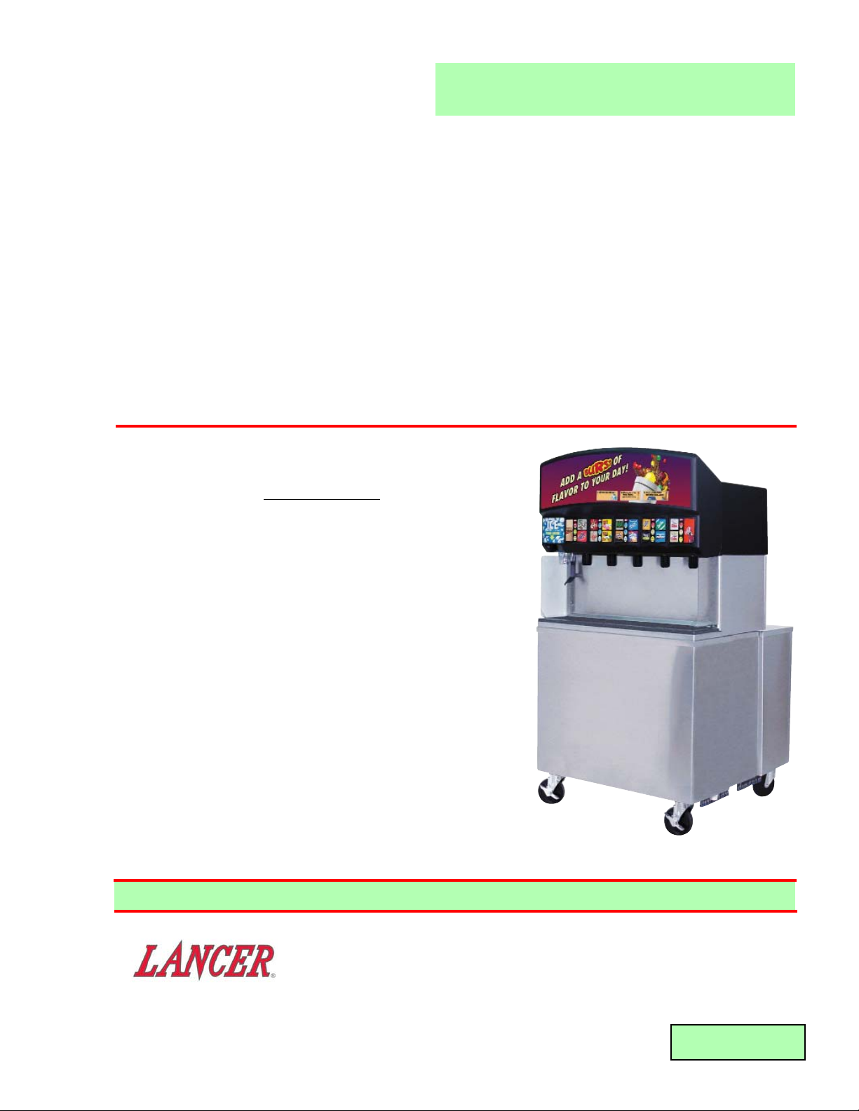
FS-18, HIGH VOLUME FREE STANDING
FLAVORSELECT
FOUNTAIN DRINK DISPENSER
Part Number 85-10018-125, 115 Volts, 60 Hz
SPECIFICATIONS
DIMENSIONS
Width 36 inches (91.4 cm)
Depth 36 inches (91.4 cm)
Height To Countertop 36 inches (91.4 cm)
To Top of Shroud (Front) 67 inches (170.2 cm)
To Top of Shroud (Rear) 61.625 inches (156.5 cm)
WEIGHT
Shipping 570 pounds (259 kg)
Empty 545 pounds (248 kg)
Operating 895 pounds (407 kg)
ELECTRICAL
Operating Voltage 115
Hertz 60
Amps 20
This manual supersedes 28-0541, dated 01/13/03.
DATE: 06/02/04
P.N. 28–0541/01
6655 LANCER BLVD. • SAN ANTONIO, TEXAS 78219 USA • (210) 310-7000
FAX SALES
• NORTH AMERICA – 210-310-7245 • INTERNATIONAL SALES – 210-310-7242 • CUSTOMER SERVICE – 210-310-7242 •
• LATIN AMERICA – 210-310-7245 • EUROPE – 32-2-755-2399 • PACIFIC – 61-8-8268-1978 •
FAX ENGINEERING: • 210-310-7096
"Lancer" is the registered trademark of Lancer • Copyright — 2004 by Lancer, all rights reserved
Please refer to the Lancer web site (www.lancercorp.com) for
information relating to Lancer Installation and Service Manuals,
Instruction Sheets, Technical Bulletins, Service Bulletins, etc.
Page 2

TABLE OF CONTENTS
SPECIFICATIONS ...................................................................................................................................COVER
TABLE OF CONTENTS ......................................................................................................................................i
MANUFACTURER’S INTRODUCTION ..............................................................................................................i
1. INSTALLATION ...........................................................................................................................................1
1.1 RECEIVING........................................................................................................................................1
1.2 UNPACKING ......................................................................................................................................1
1.3 SELECTING LOCATION....................................................................................................................1
1.4 PLUMBING.........................................................................................................................................1
1.5 ELECTRIC POWER SUPPLY ............................................................................................................2
1.6 SYSTEM CHECK ...............................................................................................................................2
2. START UP, PERIODIC MAINTENANCE, CHECKLIST, AND CLEANING GUIDE ....................................2
2.1 CLEANING AND SANITIZING INSTRUCTIONS ...............................................................................2
2.2 PERIODIC MAINTENANCE, CHECKLIST, AND CLEANING GUIDE ...............................................3
2.3 CLEANING AND SANITIZING BEVERAGE COMPONENTS - FIGAL SYSTEMS............................4
2.4 CLEANING AND SANITIZING BEVERAGE COMPONENTS - BAG-IN-BOX SYSTEMS.................5
3. HOW TO OPERATE THE LANCER FS-18 .................................................................................................6
3.1 NORMAL OPERATION ......................................................................................................................6
3.2 PROGRAMMING AND SETUP SOFTWARE.....................................................................................6
4. FS-18 TROUBLESHOOTING GUIDE .........................................................................................................7
4.1 PUSH ICE LEVER/CHUTE/ICE BUTTON AND NOTHING HAPPENS.............................................7
4.2 PUSH CHUTE MOTOR RUNS BUT NO ICE DISPENSES...............................................................7
4.3 VALVES DO NOT OPERATE .............................................................................................................7
4.4 WATER IN ICE BIN ............................................................................................................................7
5. ILLUSTRATIONS, PARTS LISTINGS, AND WIRING DIAGRAMS............................................................8
5.1 VALVE AND NOZZLE ASSEMBLY, FS-18 .........................................................................................8
5.2 BIN ASSEMBLY, FS-18 (FOR UNITS MANUFACTURED BEFORE JANUARY 2004) .....................9
5.3 BIN ASSEMBLY, FS-18 (FOR UNITS MANUFACTURED IN JANUARY 2004 OR LATER) ...........10
5.4 NOZZLE ASSEMBLY, FS-18............................................................................................................11
5.5 TOWER ASSEMBLY, FS-18.............................................................................................................12
5.6 SOLENOID ASSEMBLY, ICE DOOR, FS-18 ...................................................................................13
5.7 SHROUD ASSEMBLY, EXTERIOR VIEW, PN 82-3359, FS-18 ......................................................14
5.8 SHROUD ASSEMBLY, INTERIOR VIEW, PN 82-3351, FS-18........................................................14
5.9 ACCESS PANELS, FS-18 (FOR UNITS MANUFACTURED BEFORE JANUARY 2004)...............15
5.10 ACCESS PANELS, FS-18 (FOR UNITS MANUFACTURED IN JANUARY 2004 OR LATER) .......16
5.11 MOTOR ASSEMBLIES, FS-18.........................................................................................................17
5.12 PCB ASSEMBLY, PN 2729/01, FS-18 .............................................................................................18
5.13 INJECTION MANIFOLDS, FS-18( MANUFACTURED IN MAY 2004 OR LATER)..........................19
5.14 PLUMBING DIAGRAM - INLET AND VALVE LOCATIONS.............................................................20
5.15 FS-18 PLUMBING - FRONT PANEL TO INLET MAP .....................................................................21
5.16 WIRING DIAGRAM, FS-18 ..............................................................................................................22
i
MANUFACTURER’S INTRODUCTION
High Volume Free Standing Flavor Select Fountain Drink Dispenser
The unit is designed with the highest quality components to be user and service friendly. Most set up
parameters are easily set via a serial interface and an infrared wireless data port. All control is handled by the on board
microprocessor controller. The FS-18 is designed to seamlessly interface with the Lancer Ice Link system to provide for
a minimum of labor and maintenance by store personnel.
The FS-18 features multiple speed ice dispense from an under counter ice storage bin which is also used to chill the
product utilizing a flexible, high performance cold plate system. Up to 18 independent brands may be dispensed through
five (5) Lancer Multi-Flavor dispense nozzles. In addition, 12 ambient (non-chilled) "bonus" flavors may be added to the
drink via the flavor injection system on four (4) nozzles. Up to three (3) flavors may be added to each of four (4) nozzle
positions. In addition, chilled plain water and plain soda are available from Nozzle 3. The bonus flavors are plumbed
independently to each of the nozzles allowing for a multitude of customer pleasing drink combinations.
Supplier Name: Lancer
Address: 6655 Lancer Blvd
San Antonio, TX 78219
Phone: (800) 729-1500
Local Service Name:
Local Service Phone #:
Page 3

1. INSTALLATION
1.1 RECEIVING
Each unit is completely tested under operating conditions and thoroughly inspected before shipment.
At time of shipment the carrier accepts the unit, and any claim for damage must be made with the
carrier. Upon receiving units from the delivering carrier, carefully inspect carton for visible indication
of damage. If damage exists, have carrier note same on bill of lading and file claim with carrier.
1.2 UNPACKING
A. Set shipping carton upright on the floor.
B. Cut band and remove.
C. Open top of carton and remove interior packing.
D. Lift carton up and off of the dispenser.
E. Remove wood shipping base from the bottom of the dispenser. (Support dispenser while
removing shipping base to prevent damage to the dispenser.)
1.3 SELECTING LOCATION
A. Select a location close to a properly grounded 20 Amp electrical outlet, convenient to an open
type drain, and access for soda, water, and syrup lines. If at all possible, location should be
away from direct sunlight or other heat sources.
B. Location must insure sufficient clearance above unit to provide for servicing.
1.4 PLUMBING
NOTE
Water pipe connections and fixtures directly connected to a potable water supply and drain
plumbing connections must all be sized, installed, and maintained according to Federal, State,
and Local laws.
The water supply must be protected by means of an air gap, a backflow prevention device
(located upstream of the CO
2 injection system) or another approved method to comply with
NSF standards. A backflow prevention device must comply with ASSE and local standards.
It is the responsibility of the installer to ensure compliance.
A. General Product Configuration
1. The FS-18 is equipped with nine (9) independent soda/water inlets (see Plumbing Diagrams
in Section 5 for detail). An individual module that can be plumbed for either soda or still
water supports each nozzle location. In addition, nozzles 2, 3, 4 and 5 are provided with a
second module that will also support soda or still water. This is to provide for maximum
flexibility and performance from all circuits and products.
2. Depending on the specific use volume at the installation, the use of either one or two Lancer
Turbo Carbonators is recommended. Locations serving larger drink sizes and/or higher
drink volume will require a second Turbo Carbonator. In addition, the use of a high
capacity plain water boost system is recommended if incoming water pressure is below
50 psi under demand conditions.
B. Drain Connections
The FS-18 Features two (2) 3/4" MPT connections on the left side (from the front) of the
machine for the cold plate drain system and a third (3rd) 3/4" FPT fitting for the drip tray drain
located on the right hand side of the machine. The cold plate drains should be plumbed
independent from the drip tray drain and adequate slope and air gap should be provided to
prevent back up and potential contamination. Drain lines should be insulated with a closed cell
insulation to prevent condensation. Use caution to prevent gaps in insulation that can cause
condensation traps.
C. Water/Soda and Syrup Connections
Connect plain and carbonated water lines as desired. Refer to Figure 1 for details. All water
and chilled syrup (brands) are 3/8" barb. All ambient syrups (flavors) are 1/4" barb. Pressurize
and test the system for leaks.
1
Page 4

2
1.5 ELECTRIC POWER SUPPLY
W
ARNING:
THIS APPLIANCE MUST BE EARTHED. THIS DISPENSER MUST BE ELECTRICALLY
GROUNDED TO AVOID DANGER TO THE OPERATOR. THE POWER CORD PROVIDED HAS
A THREE PRONG GROUNDED PLUG. IF A THREE HOLED GROUNDED ELECTRICAL
OUTLET IS NOT AVAILABLE, USE AN APPROVED METHOD OF INSURING A PROPER
GROUND TO THE DISPENSER.
NOTE
Electrical connections must be installed and maintained in accordance with Federal, State, and
Local requirements.
A. The electric power supply must be a 20 amp three prong, ground convenience outlet having the
same configuration as the power cord.
B. Outlet must have proper voltage, cycles and ampere ratings. See Dispenser Name Plate for
ratings.
NOTE
Do not plug into electrical outlet unless ratings on name plate agree with local current available.
1.6 SYSTEM CHECK
W
ARNING:
ICE AUGER AND BIN AGITATION SYSTEM WILL OPERATE AUTOMATICALLY. DO NOT
PLACE HANDS OR ANY BODY PARTS WITHIN THE BIN OR IN THE ICE CHUTE.
A. With power connected, remove drip tray assembly and sanitary cover from ice bin. Raise the
tower shroud by lifting at the front. Use the provided prop rod to secure the shroud in the raised
position.
B. Push on ice cup lever to activate ice auger and bin agitation system. Verify auger rotation by
viewing through the ice chute door. Verify bin agitator rotation inside ice bin.
2. START UP, PERIODIC MAINTENANCE, CHECKLIST, AND CLEANING GUIDE
2.1 CLEANING AND SANITIZING INSTRUCTIONS
A. GENERAL INFORMATION
1. Lancer equipment (new or reconditioned) is shipped from the factory cleaned and sanitized
in accordance with NSF guidelines. This equipment must be cleaned and sanitized after
installation is complete, and the operator of the equipment must provide continuous
maintenance as required by this manual and/or state and local health department
guidelines to ensure proper operation and sanitation requirements are maintained.
NOTE
The cleaning and sanitizing procedures provided herein pertain to the Lancer equipment
identified by this manual. If other equipment is being cleaned, follow the guidelines
established for that equipment.
2. Cleaning and sanitizing should be accomplished only by trained personnel. Sanitary gloves
are to be used during cleaning and sanitizing operations. Applicable safety precautions
must be observed. Instruction warnings on the product being used must be followed.
3. Water lines are not to be disconnected during the cleaning and sanitizing of syrup lines to
avoid contamination.
4. Do NOT use strong bleaches or detergents. They tend to discolor and/or corrode various
materials.
5. Do NOT use metal scrapers, sharp objects, steel wool, scouring pads, abrasives, solvents,
etc., on the dispenser.
6. Do NOT use hot water above 140°F (60°C). This may damage certain materials.
B. REQUIRED CLEANING EQUIPMENT
1. Cleansers (for example, Ivory Liquid, Calgon, etc.) mixed with clean, potable water at a
temperature of 90 to 110 degrees Fahrenheit should be used to clean equipment. The
Page 5

3
mixture ratio, using Ivory Liquid, is one (1) ounce of cleanser to two (2) gallons of water. A
minimum of five (5) gallons of cleaning mixture should be prepared. Any equivalent
cleanser may be used as long as it provides a caustic based, non-perfumed, easily rinsed
mixture containing at least two (2) percent sodium hydroxide (NaOH). Rinsing must be
thorough and use clean, potable water which is also at a temperature of 90° to 110°F.
NOTE
Extended lengths of product lines may require that an additional volume of cleaning
solution be prepared.
2. Sanitizing solutions should be prepared in accordance with the manufacturer’s written
recommendations and safety guidelines. The solution must provide 200 parts per million
(PPM) available chlorine. A minimum of five (5) gallons of sanitizing solution should be
prepared. Any sanitizing solution may be used as long as it is prepared in accordance with
the manufacturer’s written recommendations and safety guidelines, and provides 200 parts
per million (PPM) available chlorine. Sanitizing solution is to be purged from line(s) and
equipment by flushing with product only until there is no after taste. Do not rinse with water.
NOTE
Please note that a fresh water rinse cannot follow sanitization of equipment. Purge only
with the end use product until there is no after taste in the product. This is an
NSF requirement.
Extended lengths of product lines may require that an additional volume of sanitizing
solution be prepared.
3. Other:
a. Clean cloth towels.
b. Bucket.
c. Small brush.
d. Extra nozzle.
e. Sanitary gloves.
2.2 PERIODIC MAINTENANCE, CHECKLIST AND CLEANING GUIDE
A. CLEANING AND SANITIZING THE LANCER FS-18
1. CLEANING PROCEDURE
NOTE:
This procedure should be accomplished on a daily basis, or more often (if required).
a. Carefully remove the nozzle housings by turning counter-clockwise and pulling down
from the nozzle body.
b. Wash the nozzle housings in warm soapy water.
c. Wet a clean cloth in warm soapy water.
d. While the nozzle housing is removed, wipe down the perimeter and end of the nozzle
body.
e. Rinse nozzle body with clean warm water and towel dry.
f. Make certain that the nozzle o-ring is not torn or otherwise damaged. If necessary,
replace damaged o-ring with Lancer PN 02-0231.
g. Reinstall the nozzle housing by sliding it over the nozzle body and turning clockwise to
lock in position. Use an FDA approved silicon based lubricant (if necessary).
h. With warm soapy water, wipe down all exposed unit surfaces to include splash plate,
cup rest, drip tray and bin front.
i. Pour remaining soapy water down drip tray drain.
2. ICE BIN CLEANING - START UP AND MONTHLY
a. Disconnect Dispenser from the power source
b. Melt out any remaining ice from the bin.
c. Remove Splash Plate, Drip Tray and front and rear bin covers.
d. Remove Agitator Motor Assembly by disconnecting the electrical connector from the
harness and lifting the motor assembly straight up off of the alignment pins.
Page 6
4
e. Remove the Upper Agitator Shaft, Agitator Assembly and Lower Agitator Shaft.
f. In a similar fashion, remove the auger assembly in the following manner.
(1) Disconnect the electrical connector from the control board and lift the motor
assembly straight up and off of the alignment pins.
(2) Remove the four (4) screws holding the ice chute assembly to the faucet plate and
lift the upper ice chute adapter off of the auger tube.
(3) Remove the auger by lifting it straight up and out of the bin. Take care to carefully
lift the tower shroud out of the way of the auger tube.
(4) Remove the auger tube in a similar fashion by lifting it straight up and out of the bin.
g. Remove the Agitator Wheel Assembly and the Front and Rear Ice Wheel Shrouds from
the dispenser.
h. Using cleaning solution, described in Section 2.1, and a clean cloth or soft brush, clean
all removable parts, sides of Ice Bin, Ice Chute, and surface of aluminum casting.
i. Using hot water, thoroughly rinse away the cleaning solution.
j. Wearing sanitary gloves, soak a clean cloth towel in sanitizing solution, described in
Section 2.1, and wash all surfaces of removable parts, sides of Ice Bin, Ice Chute, and
surface of aluminum casting.
NOTE
Inspect all components for wear and/or damage prior to reassembly.
k. Wearing sanitary gloves, reassemble all removable parts.
l. Fill Unit with ice and replace Top Cover.
NOTE
Lancer does not recommend the use of shaved, flake, nugget, or pellet ice in the
dispenser. Dispenser will only operate properly with cube ice.
m. Reconnect Dispenser to power source and check for proper functioning.
2.3 CLEANING AND SANITIZING BEVERAGE COMPONENTS - FIGAL SYSTEMS
NOTE
Extended lengths of product lines may require more time for flushing and rinsing lines than
stated below.
A. Disconnect syrup lines from syrup containers (for example, quick disconnects, figal containers,
etc.).
B. Connect hose half of syrup line to a syrup tank filled with clean, potable, room temperature
water. Connect CO
2 supply hose to tank and pressurize.
C. Activate valve until water is dispensed. Flush and rinse line and fittings for a minimum of
60 seconds to remove all traces of residual product.
W
ARNING
TO AVOID POSSIBLE PERSONAL INJURY OR PROPERTY DAMAGE, DO NOT ATTEMPT TO
REMOVE SYRUP TANK COVER UNTIL CO
2 PRESSURE HAS BEEN RELEASED FROM TANK.
D. Disconnect CO
2 supply hose from the water filled syrup tank.
E. Following the instructions as described in Section 2.1 above, mix appropriate amount of
cleaning solution. Fill a tank with this solution. Connect hose half of syrup line to the tank.
Connect CO
2 supply hose to tank and pressurize.
F. Activate valve and draw cleaning solution through lines for a minimum of 60 seconds. This will
ensure line is flushed and filled with cleaning solution. Allow line to stand for at least
30 minutes.
G. Disconnect CO
2 supply hose from the tank.
H. Connect hose half of syrup line to a tank filled with clean, potable, water at a temperature of 90°
to 110°F. Connect CO2 supply hose to tank and pressurize.
I. Activate valve to flush and rinse line and fittings for a minimum of 60 seconds to remove all
traces of cleaning solution. Continue rinsing until testing with phenolpthalein shows that the
rinse water is free of residual detergent.
Page 7

W
ARNING
TO AVOID POSSIBLE PERSONAL INJURY OR PROPERTY DAMAGE, DO NOT ATTEMPT TO
REMOVE SYRUP TANK COVER UNTIL CO2 PRESSURE HAS BEEN RELEASED FROM TANK.
J. Disconnect CO
2 supply hose from the tank.
K. Following the instructions as described in 2.1 above, mix appropriate amount of sanitizing
solution. Fill a tank with this solution. Connect hose half of syrup line to the tank. Connect CO
2
supply hose to tank and pressurize.
L. Activate valve and draw sanitizing solution through line for a minimum of 60 seconds. This will
ensure line is flushed and filled with sanitizing solution. Allow line to stand for at least
30 minutes.
M. Disconnect CO
2 supply hose from the tank.
N. Reconnect syrup lines to syrup containers (for example, quick disconnects, figal containers, etc.)
and ready unit for operation.
O. Draw drinks to refill lines and flush the sanitizing solution from the dispenser.
NOTE
Please note that a fresh water rinse cannot follow sanitization of equipment. Purge only with the
end use product until there is no after taste in the product.
P. Test dispenser in normal manner for proper operation. Taste dispensed product to ensure there
is no off-taste. If off-taste is found, additional flushing of syrup system may be required.
Q. Repeat cleaning, rinsing, and sanitizing procedures for each valve and each circuit.
2.4 CLEANING AND SANITIZING BEVERAGE COMPONENTS - BAG-IN-BOX SYSTEMS
NOTE
Extended lengths of product lines may require more time for flushing and rinsing lines than
stated below.
A. Disconnect syrup quick disconnect coupling from syrup packages and connect coupling to a bag
valve removed from an empty Bag-in-Box (BIB) package.
B. Place syrup inlet line in a clean container filled with clean, potable, room temperature water.
C. Activate valve until water is dispensed. Flush and rinse line and fittings for a minimum of
60 seconds to remove all traces of residual product.
D. Following the instructions as described in 2.1 above, mix appropriate amount of cleaning
solution in a clean container. Place syrup inlet line in container filled with cleaning solution.
E. Activate valve and draw cleaning solution through lines for a minimum of 60 seconds. This will
ensure line is flushed and filled with cleaning solution. Allow line to stand for at least 30 minutes.
F. Place syrup inlet line in a clean container filled with clean, potable, water at a temperature of 90
°
to 110°F.
G. Activate valve to flush and rinse line and fittings for a minimum of 60 seconds to remove all traces
of cleaning solution. Continue rinsing until testing with phenolpthalein shows that the rinse water
is free of residual detergent.
H. Following the instructions as described in Section 2.1 above, mix appropriate amount of
sanitizing solution in a clean container. Place syrup inlet line in container filled with sanitizing
solution.
I. Activate valve and draw sanitizing solution through line for a minimum of 60 seconds. This will
ensure line is flushed and filled with sanitizing solution. Allow line to stand for at least
30 minutes.
J. Remove bag valve from quick disconnect coupling and reconnect syrup inlet line to syrup
package. Ready unit for operation.
K. Draw drinks to refill lines and to flush the chlorine sanitizing solution from the dispenser.
NOTE
Please note that a fresh water rinse cannot follow sanitization of equipment. Purge only with the
end use product until there is no after taste in the product. This is an NSF requirement.
L. Test dispenser in normal manner for proper operation. Taste dispensed product to ensure there
is no off-taste. If off-taste is found, additional flushing of syrup system may be required.
M. Repeat cleaning, rinsing, and sanitizing procedures for each valve and each circuit.
5
Page 8

3. HOW TO OPERATE THE LANCER FS-18
3.1 NORMAL OPERATION
A. Select the desired cup size from the cup holder.
B. Select ice dispense speed by pushing the desired rate on the ice speed select keypad on the
left-hand side of machine (ice speed defaults to middle selection if not otherwise selected).
Selection light will indicate choice.
C. Fill cup with desired amount of ice.
D. Place cup under nozzle below desired brand.
E. Select any two (2) desired bonus flavors from those available on the keypad by pushing the
flavor label once. Selection indicator light will illuminate, acknowledging selection(s).
F. Push and hold brand label to fill cup.
G. Top off cup as desired
3.2 PROGRAMMING AND SETUP SOFTWARE
A. INTRODUCTION
NOTE:
The following descriptions reflect the latest Firmware revision as of the date that this manual is
being published. Lancer reserves the right to make changes and updates as required. If you
have any questions regarding the latest versions of programs, please contact your Lancer
representative, or consult the FS-18 Training Manual.
1. The Lancer FS-18 is equipped with a serial communication port to facilitate set up and
maintenance.
2. Access to the internal functions is available through the use of a Palm Pilot Hand Held
computer along with software available from Lancer.
B. INSTRUCTIONS FOR USE OF PALM PILOT INTERFACE
1. General
The FS-18 Service Tool currently has four (4) basic sections. Each section addresses
specific related features:
a. ICE
Deals with both ice storage bin and ice delivery auger settings including agitation and
ice delivery speed
b. VALV E
Address carbonated/non-carbonated selection, end of pour soda delay settings,
includes parameters for selecting syrup brand and bonus flavors as well as bonus
flavor availability.
c. DISPENSER
Controls settings for maximum number of valves and maximum number of bonus
flavors that can be simultaneously available. Includes settings for drink top off, flavor
timeout and syrup start delay, and the beginning of the pour.
d. TEST
Includes three (3) modes: Normal, PC (portion control) Test, and Draw Test.
2. General Function
a. In all menus and sub-menus, either drop down selections are available by selecting the
down arrow or square box icon next to the desired parameter.
b. All values on the Palm Pilot will be displayed as * until the data is retrieved from the
machine.
c. Select the UPDATE button after changing the parameter to load the setting into the
FS-18. You will be prompted to verify your change prior to the change becoming active.
Select OK to accept the changes or CANCEL to return to the previous menu.
6
Page 9

C. ADJUSTMENTS AND RECOMMENDED SETTINGS
1. ICE MENU
a. AUGER SPEED MENU
The FS-18 features variable speed ice delivery. The speed is pre-set by selecting a
setting from 1 (slowest) to 10 (fastest) on the drop down menu. The other speed
adjustment (STIR) is for the auger stir speed and it also requires a setting of 1
through 10.
b. MAX ON TIME MENU
The max on time menu sets the maximum length of time that the auger can run. This
is to prevent accidental locking or rigging of the switch. The switch must be
momentarily released to reset.
The Ice Speed Switch Selection menu sets the time between the end of an ice dispense
and the default (middle) ice speed setting being automatically selected.
c. STIR TIME MENU
Sets the on time (in seconds) and the off time (in minutes) for both the bin agitation and
the auger.
2. VALVE MENU
a. Each nozzle position has individual controls to activate available bonus flavors and an
"overall" end of pour soda delay. In addition, there are the beginnings of some
rudimentary data collection functions. At this time it is not necessary to set bonus
flavors to the actual installed flavor. They do need to be set to some flavor in order to
be "on".
b. Nozzle positions 2, 3, 4 and 5 have check boxes to select either/both plain or
carbonated water for each position independently. Nozzle position 1 only
must,
therefore, be carbonated water or plain water.
c. Each brand position also has the option of an independent soda stop delay. This
compensates for the varied dynamics (speeds) with which the syrup flows through the
valve/nozzle system as compared to the soda/water. At this time, we would recommend
delays from 0.025 seconds for diet (thin) syrups to as much as 0.150 seconds for very
thick syrups (for example, orange, grape, etc.). The adjustment criteria are by visual
inspection of the flow stream during a pour.
4. FS-18 TROUBLE SHOOTING GUIDE
7
TROUBLE
CAUSE REMEDY
4.1 Push Ice Lever/Chute/ A. Dispenser not connected to A. Connect Dispenser to power
Ice Button and power source. source.*
nothing happens B. Microswitch defective. B. Replace Microswitch.*
C. Wiring Harness not plugged C. Plug in Wiring Harness.*
in at Interface Board.
D. Interface Board not properly D. Verify connection.
connected to CPU board.
D. CPU Board defective. D. Replace Board.*
4.2 Push Chute Motor runs, A. Dispenser is out of ice. A. Fill unit with ice.
but no ice dispenses. B. Auger motor is not properly B Align and re-engage.
engaged to auger.
4.3 Valves do not operate. A. Transformer tripped. A. Reset Transformer.
B. Unit not plugged in. B. Plug in Dispenser.*
4.4 Water in Ice Bin. A. Coldplate Drain is obstructed. A. Remove Drain Hose and 90 degree
fitting to obtain access to Drain.
B. Drain Hose is kinked. B. Replace Drain Hose.
* Light Emitting Diodes (LEDs) are provided on the PC Board to aid in troubleshooting electrical
difficulties. Referring to the wiring diagram included in this manual (also affixed to the electrical box
cover), the following information in Section 4 can be obtained from the LEDs.
Page 10

5. ILLUSTRATIONS, PARTS LISTINGS, AND WIRING DIAGRAMS
5.1 VALVE AND NOZZLE ASSEMBLY, FS-18
8
Item Part No. Description
1 19-0262 Valve Assy, LFCV, 0.2, Syrup
Injection, White
2 05-1385 Fitting, Fitting, Soda/Water, Out
3 19-0260 Valve Assy, LFCV, 4.5, Syrup,
Black
4 19-0261 Valve Assy, LFCV, 4.5, Soda,
Grey
5 05-1866 Elbow, 0.5 Dole x 0.25 Barb, PLS
Item Part No. Description
6 08-0105 Tubing, B44-4X, 1/4 (ID) x 0.063
(Wall)
7 54-0289 Nozzle Assy, Multiflavor
8 08-0391 Tubing, B44-4X, 0.187 (ID) x
0.312 (OD)
9 07-0443 Clamp, Hose, Oetiker, 25/64
10 82-2317/01 Back Block
R 11 02-0126 O-Ring, Back Block
12 02-0005 O-Ring, Tubing
R in margin indicates change or revision
NOTE: PLUMBING SHOWN MAY NOT BE
REPRESENTATIVE OF PLUMBING
ACTUALLY INSTALLED
1
2
3
4
5
6
12
11
10
9
8
7
Page 11

5.2 BIN ASSEMBLY, FS-18 (FOR UNITS MANUFACTURED BEFORE JANUARY 2004)
Item Part No. Description
1 10-0442 Shaft, Agitator, Upper
2 02-0406 Seal, Shaft, Motor, MB18
R 3 10-0532 Pin, 5/16”
4 03-0368 Clip
5 82-1568 Wheel
6 05-1833 Shroud, Wheel, Rear
7 05-1962 Cap, Bearing
8 05-1960 Bearing
9 10-0445 Pin, Bearing, Shaft
10 05-1961 Housing, Bearing
11 81-0475 Wheel Caster, with Brake
-- 81-0476 Wheel Caster
12 05-1822 Shroud, Wheel, Front
13 82-2961 Agitator Assy
14 10-0443 Shaft, Agitator, Lower
R 15 10-0362/02 Pin, 1/4”
R in margin indicates change or revision
9
1
2
3
4
5
14
13
12
11
6
7
8
9
10
Page 12

Item Part No. Description
R 1 82-3463 Agitator Assy
R 2 02-0556 Seal, Shaft, Motor
R 3 10-0718 Pin, 3/8”
4 03-0368 Clip
R 5 05-2277 Bushing, Locator Wheel
R 6 05-2253 Shroud, Distributor, Ice
R 7 05-2270 Wheel, Ice, Dispenser
R 8 81-0475 Wheel Caster, with Brake
R 9 10-0445 Pin, Bearing, Shaft
R 10 05-1960 Bearing
R 11 82-3464 Agitator, Assy, Lower
R 12 05-2264 Shroud, Corner, RR
R in margin indicates change or revision
(NOTE: View added in Revision 01)
10
5.3 BIN ASSEMBLY, FS-18 (FOR UNITS MANUFACTURED IN JANUARY 2004 OR LATER)
1
2
5
7
6
3
4
12
11
8
10
9
Page 13

11
5.4 NOZZLE ASSEMBLY, FS-18
Item Part
No. Description
1 54-0289 Nozzle Assy, Multi-Flavor
2 02-0231 O-Ring, Nozzle Outer
3 02-0214 O-Ring
4 05-1612 Fitting, Multi-Flavor Nozzle
5 02-0005 O-Ring
6 01-0012 Adapter, 1/4 Barb x Dole
6
5
4
3
2
1
Page 14

12 48-1784 Tube Assy, #2 Injection
13 48-1785 Tube Assy, #3 Injection
14 48-1786 Tube Assy, #4 Injection
15 48-1787 Tube Assy, #5 Injection
16 48-1788 Tube Assy, #6 Injection
17 48-1789 Tube Assy, #7 Injection
18 48-1790 Tube Assy, #8 Injection
19 48-1791 Tube Assy, #9 Injection
20 48-1792 Tube Assy, #10 Injection
21 48-1793 Tube Assy, #11 Injection
22 48-1794 Tube Assy, #12 Injection
5.5 TOWER ASSEMBLY, FS-18
12
Item
Part No. Description
1 82-2878 Foam Assy, Tube Pack
2 54-0289 Nozzle Assy, Multiflavor
3 05-0948/01 Door, Chute, IBD
4 05-0928 Trap Door, IBD
5 05-0925 Chute, IBD
6 54-0370 Chute, Ice, IBD
7 05-1866 Fitting, Outlet, Soda
8 05-1385 Fitting, Soda/Water OUT
9 02-0089 O-Ring
10 02-0005 O-Ring
11 48-1783 Tube Assy, #1 Injection
Item Part No. Description
3
4
5
2
6
TYPICAL - 5 PLACES
1
7 (TYPICAL, 9 PLACES)
8 (TYPICAL, 30 PLACES)
9 (TYPICAL, 78 PLACES)
10 (TYPICAL, 48 PLACES)
11
12
13
14
15
16
17
18
22
21
20
19
Page 15

5.6 SOLENOID ASSEMBLY, ICE DOOR, FS-18
13
Item Part No. Description
1 04-1089 Screw, 10 - 32 x 1.000
2 04-0320 Screw, 8 - 32 x 0.187
3 30-9263 Bracket, Mount, Solenoid
4 12-0195 Solenoid, D-90, 32VDC
- 23-1029 Plunger Assy
- 03-0110 Spring, Solenoid
- 04-0328 Washer, Flat, Neoprene
- 04-0327 Washer, Flat, 0.060T x
0.195 ID x 0.439 OD
- 03-0086 Ring, Retaining, #5304
- 10-0496 Pin, Solenoid
5 30-9264 Arm, Lever, Solenoid
6 05-0546 Lever, Door, IBD
- 03-0113 Ring, Retaining, 5114-12
- 03-0205 Ring, #5304-25-H
(NOTE: View added in Revision 01)
1
2
3
4
5
6
Page 16

5.7 SHROUD ASSEMBLY, EXTERIOR VIEW, PN 82-3359, FS-18
14
Item
Part No. Description
1 12-0476 Switch, Membrane, 3R, ADA
2 12-0501 Switch, 3 Products, ADA
3 12-0477 Switch, Membrane, 3L, ADA
5.8 SHROUD ASSEMBLY, INTERIOR VIEW, PN 82-3351, FS-18
Item Part No. Description
1 82-3351 Shroud Assy, FS-18
2 81-0542 Hinge, Euro, Hidden
3 04-1369 Screw, 10 - 32 x 0.625
4 30-8058 Plate, Mounting, Interconnect
Board
5 05-1835 Support, PCB
6 04-0238 Screw, 8 - 16 x 0.375, PHD
7 52-2721 PCB Assy, Interconnect, FS-18
Item Part No. Description
NOTE: CONTACT LANCER CUSTOMER SERVICE
FOR MOST CURRENT GRAPHICS, BRAND,
AND FLAVOR LABELS
3
2
1
7
6
5
4
1
3
2
Page 17

5.9 ACCESS PANELS, FS-18 (FOR UNITS MANUFACTURED BEFORE JANUARY 2004)
15
Item Part No. Description
1 30-8036 Panel, Tower, Right
2 05-1918 Shield, Ice, Right
3 05-1857 Shield, Ice, Left
4 05-2013 Stop, Ice Level
5 51-5765 Panel, Splash Assy
6 30-8037 Panel, Tower, Left
R 7 30-8038 Panel, Tower, Back
R -- 05-1843 Back, Shroud
R in margin indicates change or revision
7
6
5
4
1
3
2
NOTE: VALVES AND NOZZLES
NOT SHOWN FOR CLARITY
Page 18

1
8
3
2
4
5
6
7
5.10 ACCESS PANELS, FS-18 (FOR UNITS MANUFACTURED IN JANUARY 2004 OR LATER)
16
NOTE: VALVES AND NOZZLES NOT
SHOWN FOR CLARITY
Item Part No. Description
1 30-9050 Panel, Tower, Right
2 05-1918 Shield, Ice, Right
3 05-1857 Shield, Ice, Left
4 05-2013 Stop, Ice Level
5 51-5765 Panel, Splash Assy
6 30-9051 Panel, Tower, Left
7 05-2292 Panel, Tower, Back, Plastic
8 30-9212/01 Cover, Inlets, Inject
(NOTE: View added in Revision 01)
Page 19

5.11 MOTOR ASSEMBLIES, FS-18
17
Item Part No. Description
R 1 82-3486 Motor Assy, Agitator
R 2 82-3367 Power Supply Assy, 115V
3 82-3044 Drip Tray Assy, Foamed
4 23-1191 Cup Rest
5 27-0073 Tube, Auger
6 05-1834 Adapter, Ice Chute
R 7 51-5698/01 Frame, Tower
8 82-2990 Auger Assy
9 82-2975/01 Motor Assy, Auger
R 10 04-1428 Nut, 1/4 - 20, Knurled, Thumb
R in margin indicates change or revision
NOTE: VALVES AND NOZZLES NOT
SHOWN FOR CLARITY
9
8
7
6
5
10
4
3
1
2
Page 20

5.12 PCB ASSEMBLY, PN 52-2729/01, FS-18
18
7ItemPart No. Description
1 52-2729/02 PCB Assy, FS-18
2 52-2386 Wire Assy, Power Relay
3 52-2383 Ribbon Wire Assy, to J324 Left,
Interconnect Board Inside
Shroud
4 52-2519 Jumper, Interlock (2X)
5 52-2518 Jumper, Key Switch
6 52-2384 Wire Assy, Power Supply
7 52-1499 Wye, Ice Sensor Harness
8 52-2657 35VAC Auger Power, Circuit
Breaker Connection (Includes
12-0449 Breaker)
9 12-0466 28VDC, Power Supply Fuse,
2AG 7A “Fast Blow”
10 52-2381 J1 Wire Assy
11 52-2380 J2 Wire Assy
12 52-2382 J3 Wire Assy
ICE LEVEL SENSORS
(NOTE: THESE ITEMS NOT AVAILABLE
ON SOME MODELS)
H
L
M
7
6
5
4
8
10
9
11
12
3
2
MDB
MULTI-DROP
BUSS - SLAVE
PORT (1)
1
P201 PALM PILOT INTERFACE CONNECTION
Page 21

19
5.13 INJECTION MANIFOLDS, FS-18 (MANUFACTURED IN MAY 2004 OR LATER)
(NOTE: View added in Revision 01)
INJECTION MANIFOLDS
(MANUFACTURED IN MAY 2004 OR LATER)
Page 22

5.14 PLUMBING DIAGRAM - INLETS AND VALVE LOCATIONS
20
(FOR UNITS MANUFACTURED
IN DECEMBER 2003 OR EARLIER)
IS4- 3
IS4 - 1
IS4 - 2
IS5 - 3
IS5 - 1
IS1 - 1
IS1 - 2
IS1 - 3
IS2 - 1
IS2 - 2
IS2 - 3
IS5 - 2
INJECTION FLAVORS
RIGHT SIDE OF UNIT
S5 - 1
WATER 2
SODA 5
WATER 5
WATER 3
SODA 4
SODA 3
SODA 2
WATER 4
SODA 1
S5 - 3
S5 - 2
S3 - 3
S2 - 4
S4 - 4
S4 - 3
S4 - 1
S4 - 2
S3 - 4
S3 - 2
S2 - 3
S3 - 1
S2 - 2
COLD PLATE INLETS
LEGEND
S1 - 1 = SYRUP, NOZZLE 1, PLACE 1
IS1 - 1 = INJECTION SYRUP, NOZZLE 1, PLACE 1
S1 - 3
S2 - 1
S1 - 1
S1 - 2
(FOR UNITS MANUFACTURED
IN JANUARY 2004 OR LATER)
RIGHT SIDE OF UNIT
IS4- 3
IS4 - 1
IS4 - 2
IS5 - 3
IS5 - 1
IS1 - 3
IS1 - 1
IS1 - 2
IS2 - 1
IS2 - 2
IS2 - 3
IS5 - 2
INJECTION FLAVORS
BACK SIDE OF UNIT
WATER 5
WATER 3
WATER 2
SODA 5
SODA 4
WATER 4
SODA 3
SODA 2
SODA 1
S5-3
S5-1
S4-4
S4-3
S4-1
S4-2
S3-4
S3-2
S3-1
S2-3
S5-2
S2-2
S2-1
COLD PLATE INLETS
(MANUFACTURED IN MAY 2004 OR LATER)
LEGEND
S1 - 1 = SYRUP, NOZZLE 1, PLACE 1
IS1 - 1 = INJECTION SYRUP, NOZZLE 1, PLACE 1
S3-3
S2-4
S1-3
S1-2
S1-1
S5 - 3
S5 - 1
WATER 5
S5 - 2
SODA 5
S4 - 4
WATER 3
BLANK
IS5 - 3
IS5 - 2
IS5 - 1
IS4 - 3
IS4 - 2
WATER 2
S3 - 3
FRONT OF UNIT
S4 - 3
S4 - 1
SODA 4
S4 - 2
S3 - 4
WATER 4
S3 - 2
S3 - 1
S2- 3
SODA 3
S2 - 4
S2 - 2
IS2 - 3
IS4 - 1
S2 - 1
IS2 - 1
IS2 - 2
S1 - 3
SODA 2
IS1 - 3
S1 - 2
IS1 - 2
SODA 1
S1 - 1
IS1 - 1
Page 23

5.15 FS-18 PLUMBING - FRONT PANEL TO INLET MAP
21
S1-1
IS1-1
IS1-2
SODA 1
S1-2
IS1-3
S1-3
IS2-1
IS2-2
SODA 2
S2-1
IS2-3
S2-2
IS4-1
S2-4
S2-3
SODA 3
WATER 2
S1-3
IS1-1
S1-1
S2-3
IS2-1
S2-1
1C
1A
2C
2A
IS1-2
IS2-2
S1-2
S2-4
S2-2
IS1-3
1B
2D
IS2-3
2B
NOZZLE 3
CARBONATED
NOZZLE 3
CARBONATED
OR PLAIN WATER
OR PLAIN WATER
S3-1
S2-3
IS2-2
S2-1
SODA 3
WATER 5
S2-4
S5-3
S5-1
WATER 3
S4-4
WATER 2
S4-3
S1-1
S2-4
S1-2
S3-3
S1-3
S5-2
S2-1
S5-3
S2-2
SODA 1
S2-3
S3-3
WATER
S3-1
S4-3
IS4-1
S4-1
S5-2
IS5-1
S5-1
3C
3A
4C
4A
5B
5A
IS4-2
IS5-2
S3-4
S3-2
S4-4
S4-2
S5-3
3D
SODA
3B
4D
IS4-3
4B
5C
IS5-3
NOZZLE 3
CARBONATED
NOZZLE 4
CARBONATED
NOZZLE 5
CARBONATED
WATER 3
S3-3
OR PLAIN WATER
OR PLAIN WATER
OR PLAIN WATER
IS4-2
IS4-3
IS5-1
IS5-2
IS5-3
BLANK
WATER 5
S5-2
S5-3
S3-1
S3-2
WATER 4
S3-4
S4-2
SODA 4
S4-1
S4-3
S4-4
SODA 5
S5-1
S4-1
SODA 1
S4-2
S1-3
SODA 2
S1-2
S3-4
S1-1
S3-2
SODA 5
SODA 4
WATER 4
S5-2
S3-3
S3-1
SODA 3 SODA 2
S3-2
WATER 4
S3-4
SODA 4
S4-2
SODA 5
S4-1
WATER 2
S4-3
WATER 3
S4-4
WATER 5
S5-1
ICE
BTM ROW
TOP ROW
PLATE
FAUCET
SOFT
PLUMB
TOP ROW
BTM ROW
BIN
ASSY
Page 24

5.16 WIRING DIAGRAM, FS-18
22
(NOTE: View added in Revision 01)
B
W
TO ICE MAKER
(CURTAIN SWITCH)
ICE
LEVEL
PROBE
RANCO
ELECTRONIC
TEMPERATURE
CONTROL
BB
B
W
B
W
B
ICE LEVER
DOOR
SOLENOID
W
B
AGITATOR MOTOR
PLUGS INTO
AGITATOR MOTOR RELAY
R
W
W
B
INTERCONNECT BOARD
AUGER
MOTOR
B
INTERCONNECT BOARD
B
W
B
W
B
B
W
B
W
B
AGITATOR
RELAY
W
TO VALVE MODULES
POWER SUPPLY ASSEMBLY
TRANSFORMER
BL
W
W
B
B
B
BR
W
B
115V
BREAKER
W
W
B
B
W
B
W
115VAC IN
BL
G
BR
GRND
W
W
R
B
B
W
W
R
24V
LIGHT
B
W
 Loading...