

Page 1
INSTALLATION AND SERVICE MANUAL
FOR
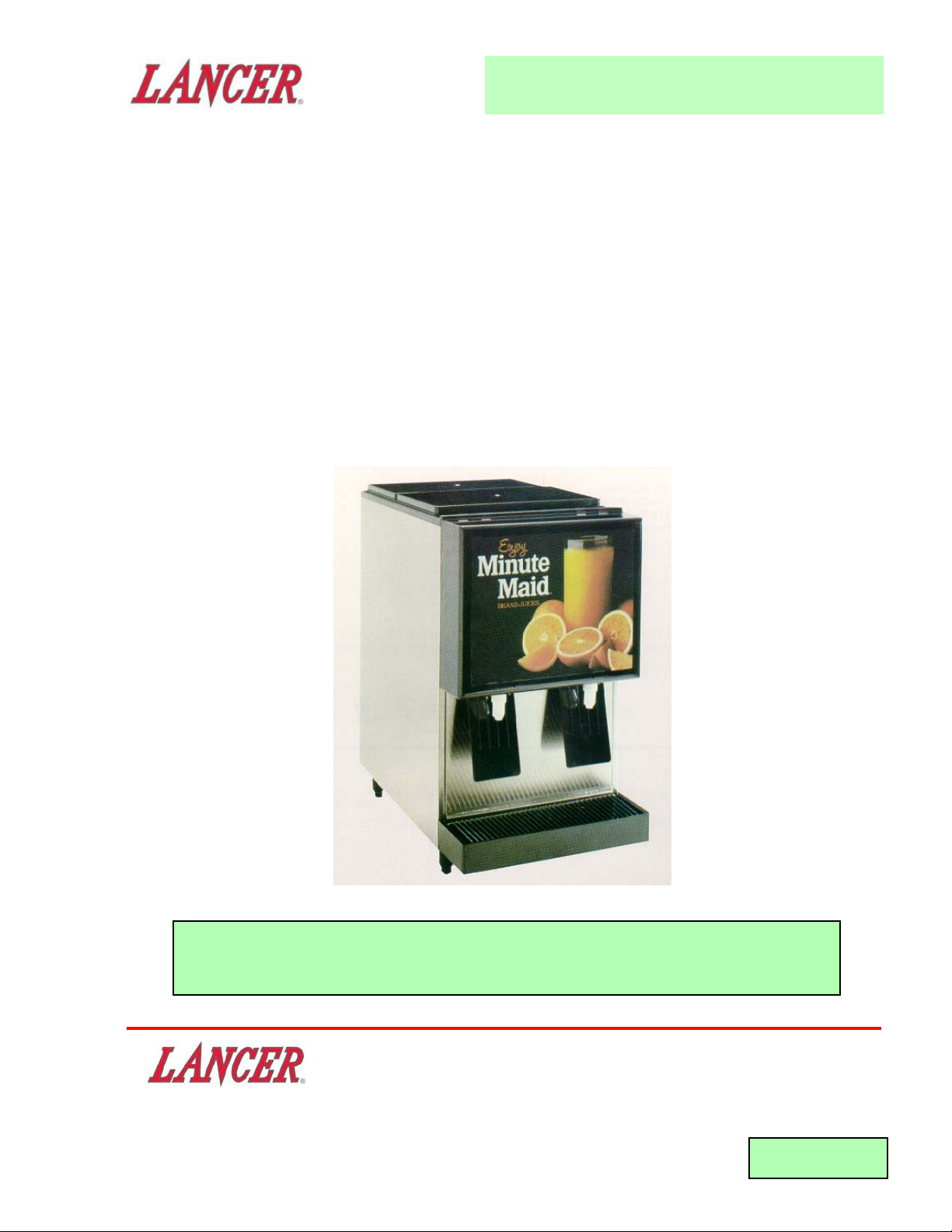
CENTURION II JUICE DISPENSER
Part Number 85-0055, 115 Volts, 60 Hz
Part Number 85-0056, 230 Volts, 50 Hz
This manual was reissued by Lancer in June 1997
"Lancer" is the registered trademark of Lancer • Copyright — 1997 by Lancer, all rights reserved.
"Lancer" is the registered trademark of Lancer • Copyright — 1992 by Lancer, all rights reserved.
FAX ENGINEERING: • 210-310-7096
DATE: 07/31/92
P.N. 28–0019
Please refer to the Lancer web site (www.lancercorp.com) for
information relating to Lancer Installation and Service Manuals,
Instruction Sheets, Technical Bulletins, Service Bulletins, etc.
6655 LANCER BLVD. • SAN ANTONIO, TEXAS 78219 USA • (210) 310-7000
FAX SALES
• NORTH AMERICA – 210-310-7245 • INTERNATIONAL SALES – 210-310-7242 • CUSTOMER SERVICE – 210-310-7242 •
• LATIN AMERICA – 210-310-7245 • EUROPE – 32-2-755-2399 • PACIFIC – 61-8-8268-1978 •
Page 2

TABLE OF CONTENTS
TABLE OF CONTENTS ......................................................................................................................................i
SPECIFICATIONS............................................................................................................................................ iii
1. INSTALLATION (CENTURION II) ...............................................................................................................1
1.1 RECEIVING........................................................................................................................................1
1.2 UNPACKING ......................................................................................................................................1
1.3 SELECTING COUNTER LOCATION .................................................................................................1
1.4 CONNECTING TO WATER SUPPLY.................................................................................................2
1.5 FILLING UNIT WITH WATER ............................................................................................................2
1.6 CONNECTING TO ELECTRICAL POWER .......................................................................................2
1.7 PURGING UNIT OF AIR ....................................................................................................................2
1.8 FILLING CONCENTRATE CONTAINER............................................................................................2
1.9 PRIMING CONCENTRATE PUMPS ..................................................................................................2
1.10 ADJUST WATER TO CONCENTRATE RATIO (oBRIX) ....................................................................3
1.11 CONCENTRATE LOW LEVEL INDICATOR ......................................................................................4
1.12 PRODUCT PLATES...........................................................................................................................4
2. OPERATING UNIT.......................................................................................................................................4
2.1 REFILLING CONCENTRATE CONTAINERS ....................................................................................4
2.2 CHANGING PRODUCT .....................................................................................................................4
2.3 CLEANING AND SANITIZING INSTRUCTIONS ...............................................................................4
3. PRINCIPLES OF OPERATION ...................................................................................................................5
3.1 WATER SYSTEM ...............................................................................................................................5
3.2 CONCENTRATE SYSTEM ................................................................................................................5
3.3 CONCENTRATE LOW LEVEL INDICATOR SYSTEM ......................................................................5
3.4 ELECTRONIC CONTROL SYSTEM..................................................................................................6
3.5 DISPENSING PADDLE SYSTEM ......................................................................................................6
3.6 FLUSH SYSTEM................................................................................................................................6
3.7 REFRIGERATION SYSTEM ..............................................................................................................6
4. RELOCATING OR SHIPPING UNIT ...........................................................................................................6
4.1 REMOVING AN OPERATING UNIT ..................................................................................................6
4.2 TRANSPORTING UNIT .....................................................................................................................7
4.3 SHIPPING UNIT.................................................................................................................................7
5. PERIODIC MAINTENANCE ........................................................................................................................7
5.1 LUBRICATION....................................................................................................................................7
5.2 CLEANING WATER STRAINER .......................................................................................................7
5.3 CLEANING INLET AIR FILTER..........................................................................................................7
5.4 CLEANING CONDENSER .................................................................................................................7
5.5 CLEANING CONCENTRATE CONTAINER COMPARTMENT ..........................................................7
6. REPAIR AND REPLACEMENT...................................................................................................................8
6.1 COMPLETE FRONT PANEL REPLACEMENT..................................................................................8
6.2 MAIN CONTROL PCB REPLACEMENT ...........................................................................................8
6.3 CONTROL PANEL INSTALLATION ...................................................................................................8
6.4 TRANSFORMER REPLACEMENT....................................................................................................8
6.5 MODE SWITCH REPLACEMENT .....................................................................................................8
6.6 CIRCUIT BREAKER REPLACEMENT...............................................................................................9
6.7 PADDLE SENSOR .............................................................................................................................9
6.8 CONCENTRATE PUMP .....................................................................................................................9
6.9 PUMP SUPPORT.............................................................................................................................10
6.10 CONTROL PANEL HOUSING ..........................................................................................................11
6.11 FLUSH SOLENOID VALVE ..............................................................................................................11
6.12 WATER SOLENOID VALVE .............................................................................................................11
6.13 REGULATOR ASSEMBLY ...............................................................................................................12
6.14 VACUUM BREAKER ........................................................................................................................12
6.15 ICE BANK CONTROL......................................................................................................................12
6.16 AGITATOR MOTOR .........................................................................................................................13
6.17 AGITATOR DECK.............................................................................................................................13
6.18 WATER COIL CAGE ASSEMBLY ....................................................................................................13
6.19 FRONT COVER ...............................................................................................................................14
6.20 TOP COVER ....................................................................................................................................14
6.21 WRAPPER .......................................................................................................................................14
6.22 CONDENSER FAN MOTOR ............................................................................................................14
6.23 SEALED REFRIGERATION SYSTEM .............................................................................................15
i
Page 3

TABLE OF CONTENTS (CONTINUED)
7. TROUBLESHOOTING...............................................................................................................................15
7.1 NO WATER OR CONCENTRATE ON EITHER SIDE .....................................................................15
7.2 NO WATER OR CONCENTRATE ON ONE SIDE ONLY ................................................................15
7.3 WATER ONLY - NO CONCENTRATE .............................................................................................15
7.4 CONCENTRATE ONLY - NO WATER EITHER SIDE......................................................................16
7.5 CONCENTRATE ONLY - NO WATER ON ONE SIDE ONLY ..........................................................16
7.6 NO FLUSH WATER EITHER SIDE, SYSTEM DISPENSES NORMALLY ......................................16
7.7 NO FLUSH WATER - ONE SIDE ONLY, NORMAL DISPENSE BOTH SIDES ...............................16
7.8 WATER DRIPS FROM SPOUT WHEN DRINK IS NOT BEING DISPENSED...............................16
7.9 WATER LEAKING INTO CONCENTRATE CONTAINER AND/OR CONCENTRATE TUBE...........16
7.10 WATER LEAKING INTO CONCENTRATE CONTAINER DURING FLUSH CYCLE .......................16
7.11 AIR LEAKING INTO CONCENTRATE TUBE AND/OR CONCENTRATE PUMP............................16
7.12 RATIO CANNOT BE ADJUSTED LOW ENOUGH (OR oBRIX HIGH ENOUGH)............................17
7.13 RATIO CANNOT BE ADJUSTED HIGH ENOUGH (OR oBRIX LOW ENOUGH)............................17
7.14 RATIO (oBRIX) VARIES FROM DRINK TO DRINK .........................................................................17
7.15 CONCENTRATE LOW LEVEL INDICATOR ON BUT CONCENTRATE CONTAINER IS FULL .....17
7.16 WATER CONTINUALLY OVERFLOWS FROM ICE BANK COMPARTMENT INTO
CONCENTRATE COMPARTMENT AND INTO DRIP TRAY ...........................................................17
7.17 COMPRESSOR STARTS AND CONTINUES TO RUN UNTIL FREEZE UP AND
WILL NOT CUT OFF........................................................................................................................18
7.18 WARM DRINKS................................................................................................................................18
7.19 COMPRESSOR DOES NOT START (NO HUM), CONDENSER FAN MOTOR
DOES NOT RUN AND NO ICE BANK .............................................................................................18
7.20 COMPRESSOR DOES NOT START (NO HUM), NO ICE BANK, BUT
CONDENSER FAN MOTOR RUNS.................................................................................................18
7.21 COMPRESSOR DOES NOT START, BUT HUMS ..........................................................................18
7.22 COMPRESSOR STARTS AND DOES SWITCH OFF OF START WINDING (WILL ONLY RUN
FOR A FEW SECONDS) BEFORE INTERNAL OVERLOAD SWITCHES COMPRESSOR...........18
7.23 COMPRESSOR STARTS AND RUNS A SHORT TIME, BUT SHUTS OFF ON OVERLOAD........19
8. TROUBLESHOOTING USING PCB 12 VOLT (GREEN), MOTOR OVER CURRENT (YELLOW)
AND MOTOR (RED) DIAGNOSTIC LIGHTS............................................................................................20
9. INSTALLATION OF PUSHBUTTON KITS FOR CENTURION II..............................................................21
10. CENTURION PUSHBUTTON SERVE/FLUSH SWITCH INSTALLATION ...............................................22
10.1 INSTALLATION ................................................................................................................................22
10.2 FLUSHING CENTURION.................................................................................................................23
11. ILLUSTRATIONS, PARTS LISTINGS, AND WIRING DIAGRAMS ......................................................... 24
11.1 CENTURION II - FINAL ASSEMBLY ..........................................................................................24-25
11.2 CENTURION II - PUMP REGULATOR ASSEMBLY ...................................................................26-27
11.3 CENTURION II - WATER/CONCENTRATE COMPONENT ASSEMBLY ...................................28-29
11.4 CENTURION II - REFRIGERATION ASSEMBLY .......................................................................30-31
11.5 CENTURION II - AGITATOR DECK ASSEMBLY .............................................................................32
11.6 CENTURION II - WIRING CONNECTIONS.....................................................................................33
11.7 CENTURION II - WIRING DIAGRAM ..............................................................................................34
ii
Page 4

SPECIFICATIONS
DIMENSIONS:
Width 14 1/16 inches (35.72 cm)
Depth 23 1/8 inches (58.74 cm)
Height (with legs) 25 1/2 inches (64.77 cm)
WEIGHT:
Shipping 145 pounds (65.77 kg)
Empty 130 pounds (58.97 kg)
Operating (without concentrate) 158 pounds (71.67 kg)
ELECTRICAL REQUIREMENTS (Running):
PN 85-0055 115V/60Hz 7 Amps
PN 85-0056 230V/50Hz 4 Amps
WATER REQUIREMENTS:
Minimum flowing pressure of 28 PSI (1.76 kg/cm
2
) at a flow rate of three (3) ounces (88.7 ml) per
second.
Connection 5/8 inch - 18 male flare (3/8 inch flare).
COMPRESSOR: 1/4 HP
CONCENTRATE CONTAINER CAPACITY:
Small container 128 ounces (3.78 L)
Large container 256 ounces (7.57 L)
Concentrate container
constant temperature 35
o
F (1.7oC)
Ice bath water capacity 320 ounces; 2.5 gallon (9.07 kg; 9.46 L.)
Ice bank 8 pounds (3.63 kg)
DRINK CAPACITY:
Four (4) five (5) ounce (148 cc) drinks per minute under 45
o
F (7.2oC) at 75oF (23.9oC) ambient inlet
water.
iii
Page 5

1. INSTALLATION (CENTURION II)
1.1 RECEIVING
Each unit is completely tested under operating conditions and thoroughly inspected before
shipment. At the time of shipment, the carrier accepts the unit and any claim for damage must be
made with the carrier. Upon receiving units from the delivering carrier, carefully inspect carton for
visible indication(s) of damage. If damage exists, have carrier note same on bill of lading and file a
claim with the carrier.
1.2 UNPACKING
A. Cut shipping band and remove.
B. Open top of carton and remove top inner carton pad from inside of packing box.
C. Open top inner carton pad and remove drip tray containing four (4) legs (PN 81-0112) and
accessory kit of loose parts (contents listed below).
QUANTITY
PART DESCRIPTION
PART NO.
1 Brush 22-0017
2 Flare Seal Washer 05-0017
2 Dispensing Nozzle 54-0038
1 Product Plate - Orange 05-0190
1 Product Plate - Grapefruit 05-0192
1 Product Plate - Apple 05-0194
1 Product Plate - Lemonade 05-0193
1 Product Plate - Limeade 05-0196
1 Product Plate - Pineapple 05-0197
1 Product Plate - Five Alive 05-0384
1 Product Plate - Fruit Punch 05-0385
2 Product Plate - Grape 05-0191
2 Product Plate - Cranberry 05-0195
2 Keys (for Key Switch) 81-0126
1 Inlet Water Shut Off 49-0226
2 Pushbutton Assembly 82-0482
1 Pushbutton Template 06-0341
1 Switch 12-0087
D Remove outer carton and bag by lifting up.
E. Lift unit by plywood shipping base and remove lower portion of carton.
F. Remove plywood shipping base from unit by removing screws from bottom. This is best done
by moving unit so that one side extends past edge of counter top or table allowing access to
screws on bottom of plywood shipping base.
G. Assemble legs (PN 81-0112) to unit by tilting unit. DO NOT LAY UNIT ON ITS SIDE OR BACK.
H. Inspect unit for concealed damage and if evident notify delivering carrier and file a claim against
same.
NOTE
If unit is to be transported, it is advisable to leave unit secured to plywood shipping base.
1.3 SELECTING COUNTER LOCATION
A. Select a location close to a properly grounded electrical outlet and water supply that meet the
requirement as listed in the Specifications (page iii).
1
Page 6

B. Condenser air is drawn in on the bottom of the unit and discharged out the rear of the unit. A
minimum of two (2) inches (5.08 cm) must be maintained between the back of the unit and the
wall. Failure to maintain the proper clearance space will cause the compressor to overheat and
result in premature compressor failure.
1.4 CONNECTING TO WATER SUPPLY
A. Flush water supply line thoroughly.
B. Remove drip tray by pulling up slightly and away from unit. Remove dispensing paddles by
squeezing together at top and pull down.
C. Remove splash plate by pulling bottom up slightly and then out from unit.
D. Connect the inlet water shut off to water inlet fitting on bottom of unit using a flare seal washer.
Use a backup wrench to prevent damage to strainer.
E. Connect other end of the water tube assembly to water supply line using a flare seal washer.
Open valve on water supply and check for leaks.
F. Replace splash plate, drip tray and dispensing paddles.
1.5 FILLING UNIT WITH WATER
A. Remove both lids on top of unit.
B. Disconnect check valves (feed line) from top of concentrate containers and remove concentrate
container from unit.
C. Remove yellow plug from agitator deck.
D. Using a funnel or tube, fill with water until water flows out of overflow hole into concentrate
container compartment. Facing the front of the unit, the overflow hole is in the rear wall of the
concentrate container compartment. The overflow water will drain into the drip tray.
E. Replace yellow plug.
1.6 CONNECTING TO ELECTRICAL POWER
W
ARNING
THIS UNIT MUST BE PROPERLY ELECTRICALLY GROUNDED TO AVOID POSSIBLE FATAL
ELECTRICAL SHOCK OR SERIOUS INJURY TO THE OPERATOR. THE POWER CORD IS
PROVIDED WITH A THREE PRONG GROUNDED PLUG. IF A THREE-HOLE GROUNDED
ELECTRICAL OUTLET IS NOT AVAILABLE, USE AN APPROVED METHOD TO GROUND THE
UNIT.
Plug unit power cord into electrical outlet. Compressor and condenser fan motor will run until unit
builds a complete ice bank. Agitator motor will run continuously.
1.7 PURGING UNIT OF AIR
A. Raise front cover and turn key switch ON.
B. Using a cup, actuate each dispensing paddle until a steady flow of water is obtained.
C. Turn key switch OFF.
1.8 FILLING CONCENTRATE CONTAINER
A. Thoroughly clean concentrate containers in warm soapy water. Rinse well.
B. Fill each concentrate container with concentrate. Refer to Specifications (page iii) for capacity of
concentrate containers.
C. Replace concentrate containers in unit. Be sure they are properly located and seated all the
way down. Facing unit, each concentrate container MUST have filler tube and product sensors
to the front.
D. Replace check valves (yellow elbow) in concentrate containers using a rotating movement while
pushing down.
E. Replace both lids on top of unit.
1.9 PRIMING CONCENTRATE PUMPS
A. Turn key switch ON.
B. Press and hold the mode switch to the FLUSH position.
C. Hold cup under spout and depress the dispensing paddle until a solid flow of water is obtained
through the concentrate pump.
2
Page 7
D. Release the mode switch.
E. Hold cup under spout and depress the dispensing paddle. An initial eight (8) to ten (10) ounces
(236.6 ml to 295.7 ml) of water will be dispensed before the concentrate/water mixture reaches
the nozzle.
1.10 ADJUST WATER TO CONCENTRATE RATIO (
o
BRIX)
A. Install dispensing nozzles.
B. Inlet water is distributed through a common water system with the regulator pressure preset at
25 PSIG (1.76 kg/cm
2
). With a proper water source each spout will dispense approximately
1.2 ounces (35.5 ml) of water per second. When mixed with concentrate (4 to 1 ratio), the
finished drink will be dispensed at 1.5 ounce (43 ml) per second.
C. The unit is factory preset (electronically) for the following products and ratios.
LEFT RIGHT
PRODUCT RATIO PRODUCT RATIO
Grapefruit 4:1 Orange 4:1
NOTES: Because the ratios are factory preset electronically, they are not exact and may
require a slight adjustment at the time of installation. This can be accomplished by
using a refractometer as follows:
1. Dispense a 5 or 6 ounce (147.9 or 177.4 ml) cup of product and discard.
2. Dispense a 5 or 6 ounce (147.9 or 177.4 ml) cup of product and stir thoroughly.
3. Using a refractometer, read the ratio (
o
Brix). Adjust as necessary (as explained
in Section 1.10.D below) and re-Brix.
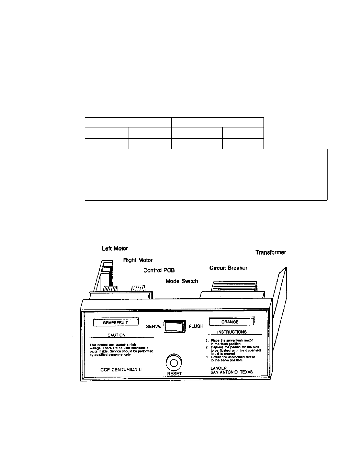
D. To adjust the
o
Brix, loosen two (2) screws on face of control panel until control panel can be
pulled partially out of control housing. Screws are captive and can be used to pull control panel
from control housing. On the main control printed circuit board (PCB) are two adjusting knobs
which control the
o
Brix of the left and right sides. The control on the left side (facing the control
panel) controls the left motor and the right control is for the right motor (refer to Figure 1).
Figure 1 - Motor Speed Controls and Flush Switch.
To adjust the
o
Brix turn the adjusting control as follows:
Decrease oBrix (less concentrate)............................................ Counter Clockwise
Increase
o
Brix (more concentrate)....................................................... Clockwise
3
Page 8
E. To set unit that has not been factory preset for a product, adjust oBrix and change product plate
on control panel.
F. In some locations, the water supply pressure may be so low or may fluctuate so much that a
25 PSIG (1.76 kg/cm
2
) flowing water pressure cannot be maintained. As a result, the unit will
not dispense a product at the proper
o
Brix. In this event, the regulated water pressure should
be reduced below the local inlet water supply pressure so that a proper oBrix can be maintained.
Reducing the regulated water pressure will reduce the finished product flow rate. Normally, the
minimum recommended setting is 15 PSIG (1.06 kg/cm
2
) flowing. To reset regulator, refer to
Section 6.13.K-Q.
G. Readjust
o
Brix as necessary.
H. Slide control panel into control housing and tighten screws finger tight. Be sure control panel is
properly seated in control housing.
1.11 CONCENTRATE LOW LEVEL INDICATOR
A. The unit is equipped with a concentrate low level indicator system.
B. Beeper (dispensing only). At low level, the beeper will emit sound only while a drink is being
dispensed.
1.12 PRODUCT PLATES
Install the proper product plates in the holes on the front panel to indicate the product being served.
2. OPERATING UNIT
2.1 REFILLING CONCENTRATE CONTAINERS
A. Remove top cover.
B. Place opened can of COMPLETELY THAWED concentrate into concentrate container.
C. When the concentrate low level indicator is sounding, the concentrate container can be refilled
with the following quantity.
Concentrate Container Number of 42 Ounce Cans Number of 96 Ounce Cans
Small 2 1
Large 4 2
2.2 CHANGING PRODUCT
A. Flush unit until only water is dispensed from spout (refer to Section 1.9.B-C).
B. Remove lid on top of unit.
C. Remove the concentrate container and nozzle from the unit and clean with warm soapy water,
rinsing thoroughly. Fill with completely thawed concentrate and replace in unit.
D. Replace lid and nozzle.
E. Depress dispensing paddle with cup until a steady flow of pre-mixed product is obtained. Unit
is now ready to dispense. Install nozzles and check
o
Brix.
F. Change product plate on front cover to indicate new product.
NOTE
If the new product requires a different mixing ratio, refer to Section 1.10, Brixing.
2.3 CLEANING AND SANITIZING INSTRUCTIONS
A. Daily
1. Press and hold the FLUSH switch and simultaneously activate each dispensing paddle until
clear water dispenses from each nozzle.
2. Remove and wash drip tray and cup rest.
3. Wipe dispenser with clean damp cloth.
B. Weekly
1. Turn off water supply to the dispenser.
2. Press the flush position on each dispensing station to drain water from dispenser.
3. Remove lid and wash thoroughly.
4. Remove check valve (yellow elbow) from concentrate container by lifting up.
4
Page 9

5. Remove concentrate containers from dispenser.
6. Pour concentrate into clean container and place in refrigerator.
7. Clean concentrate containers in warm soapy water, rinse thoroughly.
8. Remove dispensing nozzles and dispensing paddles and wash thoroughly in warm soapy
water. Rinse well.
9. Replace nozzles and dispensing paddles.
10. Fill each concentrate container with approximately one half gallon (1.9 liters) of COOL
chlorinated sanitizing solution (minimum 50 PPM, but not to exceed 100 PPM, residual
chlorine solution) and replace containers in the dispenser. Allow sanitizing solution to stand
in containers for 10 minutes.
11. Replace check valves in concentrate containers.
12. Depress each dispensing paddle until the sanitizing solution is emptied from the concentrate
containers.
13. Remove check valves from concentrate containers and then remove containers from the
dispenser and pour out excess sanitizing solution.
14. Wipe the dispenser with clean damp cloth taking care to clean all those areas on which
product has been splashed while filling glasses.
15. Turn on the water supply to the unit.
16. Fill concentrate containers with concentrate and replace in unit.
17. Follow priming instructions (see Section 1.9) to begin to dispense product.
18. Draw drinks with end product to flush sanitizing solution from the dispenser.
NOTE
Please note that a fresh water rinse cannot follow sanitization of equipment. Purge only with
the end use product. This is an NSF requirement.
W
ARNING
REMOVE SANITIZING SOLUTION FROM DISPENSER AS INSTRUCTED. RESIDUAL
SANITIZING SOLUTION LEFT IN SYSTEM COULD CREATE HEALTH HAZARD.
19. Test dispenser in normal manner for proper operation. Taste dispensed product to ensure
there is no off-taste. If off-taste is found, additional flushing of dispensing system may be
required.
3. PRINCIPLES OF OPERATION
3.1 WATER SYSTEM
Inlet water is distributed through the strainer to the regulator which reduces the inlet water pressure
to 25 PSIG (1.76 kg/cm
2
). Water is fed from the regulator through a stainless steel tube (embedded
in the insulation of the tank assembly) and into the copper water coil where it is chilled to below 40
o
F.
Water is then fed past a vacuum breaker through a stainless steel tube (embedded in the insulation
of the tank assembly) to the front of the tank assembly and into the water solenoids. When a
dispensing paddle is depressed, the corresponding water solenoid opens allowing water to pass into
the spout and mix with concentrate.
3.2 CONCENTRATE SYSTEM
When the dispensing paddle is depressed, concentrate is drawn from the bottom of the concentrate
container up the integral dip tube and through the check valve and concentrate tube to the inlet of
the concentrate pump. It is metered by volume and pumped into the spout where it mixes with the
water. The temperature of the concentrate does not effect the
o
Brix as long as it is above 32oF. The
volume output of the concentrate pump is controlled electronically and can be adjusted to change
the
o
Brix.
3.3 CONCENTRATE LOW LEVEL INDICATOR SYSTEM
The concentrate containers have two integral stainless steel spring loaded ball sensors (on bottom
and side) of containers. When the concentrate container is in the unit, the sensors contact the
corresponding contacts in the side and bottom of the concentrate compartment. When the
concentrate level in the concentrate container is above the sensor on the side of the concentrate
container, a very small AC current is conducted by the concentrate between the sensors. When the
5
Page 10

concentrate level falls below the sensor on the side of the concentrate container the current flow is
interrupted. The electronic control PCB senses the current flow decrease and turns the low level
beeper on when the Dispense paddle is operated in the SERVE mode. The low level beeper will
not sound in the FLUSH mode.
3.4 ELECTRONIC CONTROL SYSTEM
The electric cord supplies 115 VAC to the compressor, condenser fan motor and agitator motor.
Each component has circuit protection with an automatic reset feature. The only manual reset is a
0.5 amp circuit breaker on the primary side of the control transformer accessible on the front of the
control panel. The control transformer primary is switched by the key switch and supplies power to
the pump motors, solenoids and paddle sensors via the control PCB.
All the logic functions and voltages required to operate the entire dispensing/flushing system are
provided by the control PCB. There is only one (1) motor speed control circuit, but this circuit has
two (2) available speed settings. This allows one dispensing station to operate at a time, and
enables each station to dispense at a different
o
Brix. The FLUSH cycle (flush and paddle depressed
simultaneously) forces the motor to run at the maximum speed to facilitate thorough flushing. There
are three (3) light emitting diodes (LEDs) visible on the control PCB (for access, see Section
1.10.D). These LEDs assist with Troubleshooting and Servicing (see Section 8).
3.5 DISPENSING PADDLE SYSTEM
The dispensing paddle has an integrally sealed permanent magnet which activates the sensor
behind the splash plate when the paddle is depressed. This causes the electronic system to
activate the water solenoid and concentrate pump allowing the unit to dispense product. The
dispensing paddles are removable (without tools) for cleaning. Paddles can be removed by
squeezing together the top edges of each paddle.
3.6 FLUSH SYSTEM
When the mode switch is held in FLUSH position and a paddle is depressed, the electronic system
opens the flush solenoid and allows water to flow to the check valve on the concentrate container
and simultaneously to operate the concentrate pump. Water flows through the check valve, the
concentrate pump, and the spout. The check valve positioned at the concentrate container prevents
flush water from entering the concentrate container.
3.7 REFRIGERATION SYSTEM
An ice bank is formed and maintained on the copper tube evaporator located in the water bath
compartment of the tank assembly. Water is continually circulated by the agitator motor across the
ice bank and around the copper water coil. Water temperature is maintained at 32
o
F (0oC).
Because the water compartment and concentrate compartment are an integral aluminum die casting, the
concentrate compartment is maintained at a constant 35
o
F (1.7oC) temperature. When product is
dispensed, water is drawn through the copper water coils and chilled. As the ice bank is depleted,
the ice bank control senses that the ice is melting and causes the compressor and condenser fan
motor to start. When the ice bank is rebuilt the control shuts off the compressor and condenser fan
motor. The compressor and condenser fan motor will operate periodically even though no drinks
are being dispensed in order to maintain the ice bank. If the unit is unplugged or power disrupted
while operating, the compressor will not restart for a period of time during which the refrigerant
pressures equalize (approximately 5 minutes). This feature protects the compressor from
premature failure.
4. RELOCATING OR SHIPPING UNIT
4.1 REMOVING AN OPERATING UNIT
A. Perform FLUSH operation on each side of unit until a clean stream of water is being dispensed.
B. Remove concentrate containers, clean thoroughly and replace.
C. Shut off inlet water supply. Disconnect inlet water tube from bottom of unit. About 6 ounces
(177.4 ml) of water will drain out of unit as the vacuum breaker opens allowing air into system.
D. Depress each dispensing paddle. This allows additional air into system and will cause a few
more ounces (ml) of water to drain from unit.
6
Page 11

WARNING
IF UNIT IS TO BE TRANSPORTED OR STORED WHEN AMBIENT TEMPERATURE IS 32oF
(0
o
C) OR LOWER, STEPS C AND D MUST BE PERFORMED TO PREVENT THE WATER
SYSTEM FROM FREEZING AND DAMAGING UNIT. DO NOT USE CO
2 GAS TO PURGE WATER
FROM UNIT AS IT WILL CAUSE A HEALTH HAZARD.
E. Turn key switch OFF.
F. Unplug unit power cord from electrical outlet.
G. Remove agitator deck and using plastic tubing, siphon water out of ice bath compartment. It will
be necessary to pour about 6 ounces (177.4 ml) of warm water (do NOT use extremely hot
water) into the retainer that holds the ice bank control sensing bulb. This defrosts the ice around
the retainer allowing the agitator deck to be removed. Replace agitator deck and secure with
nuts.
H. Remove drip tray and cup rest. Clean and replace. Wipe unit exterior surfaces with a clean
damp cloth.
4.2 TRANSPORTING UNIT
The best method of handling and transporting a unit is to remove legs and secure unit to a plywood
shipping base. If it is to be handled and transported with the legs assembled to the unit, special care
should be taken not to damage unit. DO NOT LAY UNIT ON SIDE OR BACK.
4.3 SHIPPING UNIT
If a unit is to be shipped by a common carrier, it must be secured to the plywood shipping base and
repacked in the original carton with the inner packaging material. For this reason, it is wise to retain
the original packing material.
5. PERIODIC MAINTENANCE
5.1 LUBRICATION
All motors are lubricated for life and require no maintenance lubrication.
5.2 CLEANING WATER STRAINER
A. Remove splash plate.
B. Close inlet water shut off valve.
C. Remove plug from strainer on regulator assembly and remove strainer screen.
D. Clean strainer screen with water. Inspect for holes or other deterioration.
E. Replace cleaned or new strainer screen. Do NOT over tighten strainer plug.
F. Open inlet water shut off valve.
G. Replace splash plate.
5.3 CLEANING INLET AIR FILTER
A. Remove splash plate.
B. Remove inlet air filter by removing spring retainers.
C. Clean air filter with water.
D. Replace air filter and spring retainer.
E. Replace splash plate.
5.4 CLEANING CONDENSER
A. Unplug unit power cord from electrical outlet.
B. Remove splash plate.
C. Remove fan guards (lower and upper).
D. Remove condenser fan motor.
E. Clean condenser with a small brush.
F. Replace condenser fan motor, fan guards and splash plate.
G. Plug unit power cord into electrical outlet.
5.5 CLEANING CONCENTRATE CONTAINER COMPARTMENT
Use only warm water and damp cloth. DO NOT USE ANY POWDER OR ABRASIVE CLEANING
COMPOUNDS THAT WILL DAMAGE FINISH.
7
Page 12

6. REPAIR AND REPLACEMENT
6.1 COMPLETE FRONT PANEL REPLACEMENT
A. Turn key switch OFF.
B. Loosen the two (2) captive screws on control panel and partially pull control panel out of the
control housing.
C. Disconnect the transformer power cord connector inside the control housing.
D. Disconnect wiring harness by grasping the ends of the 16 pin connector on the PCB. Do NOT
remove by pulling on the wires.
E. Remove control panel from control housing.
F. Replace with new control panel (refer to Section 6.3).
6.2 MAIN CONTROL PCB REPLACEMENT
A. Remove the control panel (refer to Section 6.1).
B. Disconnect the 4-pin mode switch connector and 2-pin transformer connector by grasping the
housing. Do NOT try to remove by pulling the wires.
C. Use a straight slot screwdriver to turn the 4 plastic latches 1/4 turn counter clockwise.
CAUTION
PLACE THE BAD PCB IN THE ANTISTATIC SHIPPING BAG. THE CONTROL PCB IS NOT FIELD
REPAIRABLE AND MUST BE RETURNED TO LANCER FOR REPAIR. ANY ATTEMPT TO FIELD
REPAIR WILL VOID ANY WARRANTY.
PCBs MUST BE PACKAGED IN PROTECTIVE PLASTIC SHIPPING BAG WHEN HANDLED,
STORED, TRANSPORTED OR SHIPPED. FAILURE TO DO SO MAY CAUSE DAMAGE TO THE
PCB.
D. Lift the control PCB off the stand-offs.
E. Remove the new control PCB from the antistatic plastic bag and install on the four (4) plastic
stand-offs with the alarm positioned between the mode switch and circuit breaker.
F. Turn the plastic latches 1/4 turn clockwise to secure the control board to the control panel.
G. Connect the transformer and mode switch connectors to the control board.
H. Install the control panel (refer to Section 6.3).
6.3 CONTROL PANEL INSTALLATION
A. Partially slide control panel in control housing.
B. Reconnect 16 pin connector to control PCB.
C. Reconnect the transformer power cord connector.
D. Turn key switch ON.
E. Adjust
o
Brix as required (refer to Section 1.10).
F. Slide control panel into control housing and tighten both captive screws finger tight.
6.4 TRANSFORMER REPLACEMENT
A. Remove control panel (refer to Section 6.1). Ensure that the unit is unplugged.
B. Disconnect the two (2) 0.250 inch FAST-ONS from the transformer primary (black and white
wires).
C. Disconnect the 2-pin transformer secondary connector (yellow wires) from the control PCB.
D. Remove the two (2) nuts holding the transformer to the bottom plate.
E. Remove the transformer by lifting it off the mounting studs.
F. Install the new transformer in the reverse order.
G. Install the control panel (refer to Section 6.3).
6.5 MODE SWITCH REPLACEMENT
A. Remove the control panel (refer to Section 6.1).
B. Remove the control PCB (refer to Section 6.2).
C. Remove the eight (8) screws securing the transformer and control PCB mounting plate to the
front panel.
D. Record the wire color and terminal position of the mode switch harness to ensure installation will
be correct.
8
Page 13

E. Remove the two (2) 0.110 inch FAST-ON connectors from the back of the mode switch.
F. Remove the securing nut from the back of the switch and push the switch through the front of
the control panel.
NOTE
This switch must be positioned so the spring return (momentary) position corresponds to the
FLUSH position.
G. Install the new switch in the reverse order.
H. Install the control panel (refer to Section 6.3).
6.6 CIRCUIT BREAKER REPLACEMENT
A. Remove the control panel (refer to Section 6.1).
B. Remove the control panel (refer to Section 6.2).
C. Remove the eight (8) screws securing the transformer and control PCB plate to the control
panel.
D. Disconnect the two (2) 0.250 inch FAST-ON connectors from the back of the circuit breaker.
E. Remove the retaining clip from the back of the circuit breaker.
F. Push the circuit breaker out of the front of the control panel.
H. Install in the reverse order.
I. Install the control panel (refer to Section 6.3).
J. Turn key switch ON.
6.7 PADDLE SENSOR
A. Turn key switch OFF.
B. Remove dispensing paddles and drip tray.
C. Remove splash plate.
D. Unplug sensor from harness.
E. Loosen nut on back of sensor.
F. Remove sensor from bracket.
G. Replace with new sensor and adjust so that sensor face is about 1/8 inch (about 3.175 mm) from
the splash plate.
H. Replace splash plate.
I. Replace dispensing paddles and drip tray.
J. Turn key switch ON.
NOTE
Sensors are sealed units and cannot be repaired. If the sensor is shorted (burned out), the PCB
will shut off automatically. When the sensor is replaced, the PCB will automatically reset.
6.8 CONCENTRATE PUMP
CAUTION
THE MOTOR IS A FACTORY SEALED UNIT AND IS NOT FIELD REPAIRABLE. ANY ATTEMPT
TO FIELD REPAIR WILL VOID WARRANTY.
A. Replacement
1. If concentrate pump will operate, depress FLUSH mode until a clear stream of water is
dispensed.
2. If concentrate pump will not operate, proceed to Step 3.
3. Turn key switch OFF.
4. Remove check valve from concentrate container by pulling up.
5. Remove spout by loosening nut (turn counter clockwise) and pulling spout down. Do NOT
lose o-ring between spout and threaded adaptor.
6. Remove inlet elbow by pulling up.
7. Remove concentrate pump by pulling out of pump support.
8. Replace new concentrate pump by reversing above procedure.
9. Turn key switch ON.
10. Readjust
o
Brix (refer to Section 1.10.)
9
Page 14

CAUTION
THE MOTOR IS A FACTORY SEALED UNIT AND IS NOT FIELD REPAIRABLE. ANY ATTEMPT
TO FIELD REPAIR WILL VOID WARRANTY.
B. Repair.
1. Remove the four (4) knurled screws on top of pump face plate.
2. Remove face plate and clean with water. If any inner surface exposed to the impeller is
grooved or severely worn, replace the damaged parts.
3. Remove the impeller and clean with plain water. DO NOT use pliers or sharp instrument to
remove the impeller. Be careful not to scratch or deface inner concentrate pump body. If
the impeller is cut, nicked or severely worn, replace.
4. Remove four (4) Phillips screws and separate concentrate pump body and the motor to
expose the shaft seal (black). The shaft seal must be replaced if the inner cylindrical
(seal/shaft) surface and/or the outer cylindrical (seal/pump body) surface are grooved,
scratched or excessively worn. If the seal has failed prematurely, it is advisable to replace
both the seal and pump body. Clean only with plain water.
CAUTION
USE ONLY LANCER LUBE. USE OF OTHER GREASE, LUBRICANT OR COMPOUNDS
MAY CAUSE OFF TASTE, ODOR AND/OR DAMAGE TO UNIT AND WILL VOID
WARRANTY.
a. To replace seal, carefully press seal out of body.
b. Lubricate inside and outside of seal with Lancer Lube (PN 15-0046). Press seal into
body until completely seated.
5. Coat motor shaft and boss at base of shaft with Lancer Lube. Carefully assemble pump
body to motor using a rotating motion so as not to damage shaft seal. There is only one (1)
four-hole, motor pump body combination. There is a small nipple on the pump body that
corresponds with a small dimple in the motor casing; these must match up for correct
installation. Replace screws and tighten evenly 1/4 turn after finger tight. DO NOT
TIGHTEN EXCESSIVELY.
6. Install impeller being careful to flex all impeller arms in a clockwise fashion (motor shaft will
rotate counter clockwise). Align the flats on the shaft and impeller and gently push impeller
onto the shaft until seated against back pump body surface.
CAUTION
IF CONCENTRATE PUMP IS NOT PROPERLY ASSEMBLED, IT CAN CAUSE A PUMP
MOTOR OVERLOAD CONDITION AND WILL CAUSE THE CONTROL PCB TO GO INTO
OVER CURRENT LIMITING (YELLOW LED ON, WHILE TRYING TO DISPENSE).
7. Replace o-ring, face plate and four (4) knurled screws. The sequence in which the screws
are tightened should be rotational (in order of 3, 6, 9 and 12 o'clock positions). DO NOT
TIGHTEN EXCESSIVELY.
6.9 PUMP SUPPORT
A. Depress FLUSH mode and the dispensing paddles until a clear stream of water is dispensed.
B. Remove check valve from concentrate container.
W
ARNING
DISCONNECT THE POWER CORD FROM THE ELECTRICAL OUTLET.
C. Remove control panel (refer to Section 6.1).
D. Remove drip tray, dispensing paddles and splash plate.
E. Remove spout and concentrate pumps.
F. Remove four (4) screws attaching pump support to frame.
G. Release key switch connector from inside control housing.
H. Remove pump support by pulling forward. Disconnect electrical connectors from pump support.
I. To reassemble, reverse above procedure.
10
Page 15

6.10 CONTROL PANEL HOUSING
WARNING
DISCONNECT THE POWER CORD FROM THE ELECTRICAL OUTLET.
A. Remove control panel (refer to Section 6.1).
B. Release key switch connector from inside control housing.
C. Remove four (4) screws attaching control housing to frame (second and third on each flange of
control housing).
D. Pull control housing forward and feed 16-pin connector and harness through housing.
E. To reassemble, reverse above procedure.
6.11 FLUSH SOLENOID VALVE
A. Turn key switch OFF.
B. Close inlet water shut off valve.
C. If coil is defective, remove wiring harness by pulling off quick connect terminals. Replace coil
and reassemble.
D. If solenoid valve is defective, remove plastic tubes (inlet and outlet) by loosening tube fitting
nuts.
E. Remove two (2) screws attaching solenoid valve bracket to tank assembly.
F. Remove two (2) screws attaching solenoid valve to bracket.
G. Replace solenoid valve and reverse above procedure.
NOTE
If the coil is shorted (burned out or a short exists for any other reason in the +12 VDC solenoid
wiring, the control PCB will shut off automatically (Green LED OFF). When the short is removed
(repaired) the control PCB will automatically reset.
6.12 WATER SOLENOID VALVE
W
ARNING
DISCONNECT THE POWER CORD FROM THE ELECTRICAL OUTLET.
A. Turn key switch OFF.
B. Close inlet water shut off valve.
C. Remove pump support (refer to Section 6.9).
D. If solenoid is leaking, remove nut on end of coil and remove coil. Unscrew armature housing
and remove spring and armature. Check for foreign matter or wear. If foreign material is
present, open water supply and flush. Reassemble.
E. If coil is defective, remove wiring harness by pulling off quick connect terminals. Replace coil
and reassemble.
CAUTION
SOLENOID ASSEMBLY IS NOT NORMALLY FIELD REPAIRABLE. INLET AND OUTLET
ADAPTORS MUST BE FACTORY ASSEMBLED TO SOLENOID TO OBTAIN PROPER
POSITIONING AND OVERALL LENGTH.
F. If solenoid valve is defective, replace as follows.
1. Remove adaptor from solenoid by pulling out.
2. Loosen swivel nut on inlet side of solenoid assembly. Use a backup wrench. Remove
solenoid assembly and old flare seal washer from inside of swivel nut.
3. Reassemble new solenoid assembly using flare seal washer (PN 05-0011). Tighten swivel
nut 1/4 turn after finger tight. USE A BACKUP WRENCH.
4. Connect wiring harness to solenoid assembly.
G. Assemble adaptor assembly to pump support. Make sure hex portion of adaptor assembly is
properly seated in back of pump support. Lubricate o-rings on adaptor.
H. Assemble in reverse order.
I. Replace pump support on unit with four (4) screws.
J. Replace concentrate pump, spout and inlet elbow fitting.
K. Turn key switch ON.
11
Page 16

L. Check oBrix as required (refer to Section 1.10).
M. Slide control panel into control housing and tighten both captive screws finger tight.
6.13 REGULATOR ASSEMBLY
A. Unplug unit power cord from electrical outlet.
B. Remove drip tray, dispensing paddles and splash plate.
C. Close inlet water shut off valve.
D. Remove tube assembly from inlet of regulator assembly. USE A BACKUP WRENCH TO
PREVENT DAMAGE TO STRAINER.
E. Loosen nuts on outlet fitting.
F. Remove nut on mounting bracket.
G. Remove regulator assembly.
H. Repair or replace defective parts. Use approved thread sealant.
I. Replace regulator assembly and connect inlet water shut off being careful to include flare seal
washer.
J. Tighten nuts on copper outlet tube 1/4 turn after finger tight. Open inlet water shut off valve and
check for leaks.
K. Remove cap on test connection on bottom of repaired or new regulator and connect test gauge.
L. Replace dispensing paddle.
M. Turn key switch ON.
N. Dispense one (1) six (6) ounce (177.4 ml) drink and discard. Set regulator at 25 PSIG
(1.76 kg/cm
2
) flowing while activating the dispensing paddle.
O. Remove test gauge and replace test connection cap.
P. Reassemble unit.
Q. Check
o
Brix and adjust as necessary (refer to Section 1.10).
6.14 VACUUM BREAKER
A. Close inlet water shut off valve.
B. Remove lid over agitator deck.
C. Remove vacuum breaker by loosening adaptor nut on top side of tank assembly.
D. Remove cap from end of vacuum breaker.
CAUTION
USE ONLY LANCER LUBE. USE OF OTHER GREASE, LUBRICANT OR COMPOUNDS MAY
CAUSE OFF TASTE, ODOR AND/OR DAMAGE TO UNIT AND WILL VOID WARRANTY.
E. Inspect umbrella check valve and o-rings. Replace as necessary and reassemble. Lubricate
o-rings only with Lancer Lube.
F. Open inlet water shut off valve and check for leaks.
G. Dispense several drinks while observing vacuum breaker. NO WATER SHOULD COME OUT
OF HOLE ON END OF VACUUM BREAKER CAP.
6.15 ICE BANK CONTROL
W
ARNING
DISCONNECT THE POWER CORD FROM THE ELECTRICAL OUTLET.
A. Remove lid over agitator deck.
B. Unplug wiring harness from agitator deck.
C. Remove black rubber seal from retainer (around the ice bank control capillary tube).
D. Pour about 12 ounces (354.8 ml) warm (NOT HOT) water into retainer to melt ice around
control bulb.
E. Pull control bulb out of retainer.
F. Disconnect control from wiring harness.
G. Remove one (1) screw and loosen one (1) screw holding control bracket to agitator deck.
Remove defective control. Control is NOT repairable.
H. Install new control. MAKE SURE CONTROL BULB IS ALL THE WAY DOWN INTO RETAINER.
I. Replace black rubber seal.
J. Remove four (4) screws holding agitator motor bracket to agitator deck.
K. Pull agitator motor up so that propeller can be inspected. If any blades are broken due to ice
bank freeze up, replace propeller.
12
Page 17

L. Remount agitator motor to agitator deck.
M. Connect wiring harness to agitator deck. If control failed and caused unit to freeze up and the
unit is still frozen at time of repair, the compressor may start and operate for a short period of
time, while ice is built around control bulb, causing control to shut off compressor. At time of
repair, if unit is frozen up to the extent that the water coils are frozen and product cannot be
dispensed, it will be necessary to partially defrost ice bank. If defrost is necessary, pour warm
water into water bath.
NOTE
Instead of defrosting ice bank, the unit power cord can be left unplugged from electrical outlet
for about six (6) to eight (8) hours and then plugged back into electrical outlet by operator.
N. Replace lid.
6.16 AGITATOR MOTOR
W
ARNING
DISCONNECT THE POWER CORD FROM THE ELECTRICAL OUTLET.
A. Remove lid over agitator deck.
B. Unplug wiring harness from agitator deck.
C. Remove four (4) screws holding agitator motor bracket to agitator deck.
D. Disconnect agitator motor from wiring harness and remove.
E. Remove propeller from shaft if damaged. Inspect propeller to be sure no blades are broken.
F. Replace agitator motor and propeller by reversing above procedure.
6.17 AGITATOR DECK
W
ARNING
DISCONNECT THE POWER CORD FROM THE ELECTRICAL OUTLET.
A. Remove lid over agitator deck.
B. Unplug wiring harness from agitator deck.
C. Remove two (2) nuts holding agitator deck to tank assembly.
D. If unit has an ice bank, remove seal and pour about 12 ounces (354.8 ml) of warm water into
retainer to defrost and detach from ice bank.
E. Lift agitator deck out of unit.
F. To reassemble, reverse above procedure.
NOTE
The retainer is attached to the agitator deck with a sleeve which is pressed onto the retainer.
The sleeve must be tight against bottom of agitator deck so that the retainer is held firmly to the
agitator deck. If the retainer is loose, the ice bank size will vary and may cause a freeze-up of
the unit.
6.18 WATER COIL CAGE ASSEMBLY
W
ARNING
DISCONNECT THE POWER CORD FROM THE ELECTRICAL OUTLET.
A. Close inlet water shut off valve.
B. Remove agitator deck (refer to Section 6.17).
C. Remove water from ice bank compartment.
D. Loosen tubing nuts on water coil.
E. Remove four (4) nuts holding cage assembly to bottom of tank.
F. Remove cage assembly from tank.
G. Remove defective water coil from cage assembly.
H. Reassemble cage assembly in tank by reversing procedure. Tighten water coil tubing nuts 1/4
turn after finger tight.
I. Open inlet water shut off valve and check for leaks.
J. Refill ice bank compartment to overflow port.
K. Replace agitator deck and lid.
13
Page 18

6.19 FRONT COVER
CAUTION
CARE SHOULD BE USED WHEN HANDLING FRONT COVER NOT TO SCRATCH OR MAR
SURFACE. WHEN CLEANING USE ONLY DAMP CLEAN CLOTH.
A. Lift front cover up so that it rests on top cover.
B. Loosen two (2) wing nuts (DO NOT REMOVE) holding retainer to front edge of top cover.
C. Slide retainer down.
D. Pull front cover forward and remove.
E. To reassemble, reverse above procedure.
6.20 TOP COVER
A. Flush both sides of unit.
B. Turn key switch OFF.
C. Remove both lids.
D. Remove front cover.
E. Remove check valves from concentrate tubes.
F. Remove concentrate containers.
G. Loosen three (3) screws (DO NOT REMOVE) holding top cover to frame at front of unit.
H. Loosen three (3) screws (DO NOT REMOVE) holding top cover to frame at rear of unit.
I. Lift top cover up and off unit.
J. To reassemble, reverse above procedure.
6.21 WRAPPER
W
ARNING
DISCONNECT THE POWER CORD FROM THE ELECTRICAL OUTLET.
A. Remove front cover (refer to Section 6.19) and top cover (refer to Section 6.20).
B. Remove drip tray, dispensing paddles and splash plate.
C. Remove eight (8) screws on front of unit [four (4) on each side]. Locations are as follows.
1. Top and bottom in flange of control housing.
2. Two (2) in wrapper below pump support.
NOTE
It is not necessary to remove control housing and pump support when removing wrapper.
D. Spread wrapper at front of unit slightly on each side in order to clear frame. Push wrapper
toward back of unit until wrapper is free of frame.
CAUTION
CLEAN WRAPPER ONLY WITH DAMP CLEAN CLOTH, OR APPROVED NON-ABRASIVE SPRAY
OR LIQUID STAINLESS STEEL CLEANER.
E. To reassemble, reverse above procedure being sure that cutout for power cord in rear of
wrapper seats properly.
6.22 CONDENSER FAN MOTOR
W
ARNING
DISCONNECT THE POWER CORD FROM THE ELECTRICAL OUTLET.
A. Disconnect fan motor electrical cord from junction box.
B. Remove four (4) screws holding fan guards.
C. Remove four (4) nuts holding fan motor bracket to base of unit and remove from unit.
D. Clean condenser with a brush.
E. Remove fan motor from bracket.
F. Remove fan blade from fan motor. Do NOT bend fan blade.
G. To reassemble, reverse above procedure.
14
Page 19

6.23 SEALED REFRIGERATION SYSTEM
A. Compressor replacement.
W
ARNING
DISCONNECT THE POWER CORD FROM THE ELECTRICAL OUTLET.
1. Remove wrapper (refer to Section 6.21).
2. Disconnect all wiring from compressor.
3. Tap into high side pigtail tube on dryer capillary assembly and slowly vent refrigerant.
4. Unsolder suction tube at compressor.
5. Unsolder high side tube at compressor.
6. Remove compressor from unit.
7. Remove low side pigtail tube from defective compressor.
8. Solder low side pigtail tube to new compressor. USE ONLY 95-5 SILFOS SOLDER AND
SILFOS FLUX.
9. Smooth end of suction tube and high side tube with refrigeration sandpaper.
10. Install new compressor in unit. Replace four (4) hold down clips.
11. Coat outside end of high side tube with Silfos Flux. Insert in compressor. SOLDER WITH
95-5 SILFOS SOLDER.
12. Coat outside end of tube on compressor with Silfos Flux. Attach suction tube and
SOLDER WITH 95-5 SILFOS SOLDER.
13. Connect vacuum pump to high side pigtail on compressor and low side pigtail tube on dryer
capillary assembly. If connecting to only one side use high side.
14. Vacuum unit for as long as necessary to ensure a 200 micron vacuum. Normally overnight
is more than adequate.
15. Charge with 6 ounces (177.4 ml) of R-12 refrigerant using a properly calibrated charging
cylinder. Care must be taken to ensure a charge with ± 1/8 ounce (3.5 g).
16. Carefully leak check all solder joints.
17. To reassemble, reverse above procedure.
7. TROUBLESHOOTING (Causes are listed in order of probability)
TROUBLE
CAUSE REMEDY
7.1 No water or concentrate A. Key switch OFF. A. Turn key switch ON.
on either side. B. Unit not connected to B. Connect unit power cord to
electrical outlet. electrical outlet.
C. Electrical circuit breaker on C. Reset circuit breaker by
control box assembly tripped. depressing button on control box.
D. Power supply electrical D. Reset breaker or replace fuse. If
breaker tripped or fuse blown. problem persists:
1. Check unit for electrical short-wiring, compressor, fan motor,
etc.
2. Electrical circuit overload.
Switch to another circuit.
7.2 No water or concentrate A. Control PCB defective. A. Replace PCB.
on one side only. B. Sensor not adjusted properly B. Adjust sensor to move it closer to
in relation to paddle. paddle.
C. Sensor not connected to C. Connect sensor to wiring harness.
wiring harness.
D. Defective sensor. D. Replace sensor.
E. Water solenoid valve defective E. Repair or replace water solenoid
and concentrate pump not valve and properly install
properly installed in pump concentrate pump in pump support
support or defective. or replace same.
F. Defective paddle. F. Replace paddle.
7.3 Water only - no A. Out of concentrate. A. Refill concentrate container.
concentrate.
(7.3 continued next page)
15
Page 20

(7.3 continued)
B. Check valve not properly B. Push check valve all the way into
installed in concentrate concentrate tank.
container.
C. Concentrate pump not C. Properly install (push in)
properly installed in pump concentrate pump in pump support.
support.
D. Concentrate pump defective. D. Repair or replace concentrate
pump.
E. Check valve clogged. E. Remove and clean check valve.
F. Large lumps in concentrate. F. Defrost concentrate.
G. Air leak in concentrate inlet G. 1. Replace both o-rings on check
tube. valve.
2. Replace concentrate tube.
H. Control PCB defective. H. Replace control PCB.
I. Concentrate tube kinked. I. Remove kink in tube.
7.4 Concentrate only - A. Inlet water shut off valve A. Turn inlet water shut off valve ON.
no water either side. turned OFF.
B. Inlet water strainer dirty/ B. Remove strainer and clean.
clogged.
C. Water coils frozen. C. Replace ice bank control. Check
umbrella check valve in vacuum
breaker and replace if necessary.
D. Water regulator not properly D. Connect test gauge to each water
set and not passing water. regulator and reset to proper
pressure.
E. Water solenoid valve not E. Connect wiring harness to water
connected to wiring. solenoid valves.
F. Control PCB defective. F. Replace control PCB.
7.5 Concentrate only - A. Defective control PCB. A. Replace control PCB.
no water on one side B. Water solenoid valve not B. Connect wiring harness to water
only. connected to wiring harness. solenoid valve.
C. Defective coil on water C. Replace coil.
solenoid.
D. Defective water solenoid D. Repair or replace water solenoid
valve. valve.
7.6 No flush water either A. Flush solenoid valve not A. Connect wiring harness to water
side, system dispenses. connected to wiring harness. flush solenoid valve.
normally. B. Control PCB defective. B. Replace PCB.
C. Flush water line from water C. Unpinch.
regulator pinched.
7.7 No flush water - one A. Pinched flush water tube of A. Replace flush water tube.
side only, normal effected side.
dispense both sides. B. Defective flush solenoid. B. Replace flush solenoid.
C. Control PCB defective. C. Replace control PCB.
7.8 Water drips from spout A. Defective water solenoid A. Repair or replace water solenoid
when drink is NOT valve. valve.
being dispensed.
7.9 Water leaking into A. Flush solenoid valve leaking. A. Repair or replace flush solenoid
concentrate container valve.
and/or concentrate tube. B. Check valve defective. B. Repair or replace check valve.
7.10 Water leaking into A. Check valve leaking. A. Repair or replace check valve.
concentrate container
during flush cycle.
7.11 Air leaking into A. Air leaking into check valve A. Push tube onto check valve.
concentrate tube and/or from flush and/or concentrate Replace tube if necessary.
concentrate pump. tube.
(7.11 continued next page)
TROUBLE CAUSE REMEDY
16
Page 21

(7.11 continued)
. B. Air leaking into pickup tube B. Replace two o-rings on exterior
of concentrate container. of check valve.
C. Air leaking into elbow. C. Push concentrate tube onto elbow.
Replace tube if necessary.
D. Air leaking into concentrate D. Replace two o-rings on elbow.
pump at elbow.
E. Air leaking into concentrate E. 1. Replace face plate o-ring.
pump. 2. Replace seal in concentrate
pump body.
7.12 Ratio cannot be A. Regulated water pressure A. Use test gauge and adjust water
adjusted low enough too high. pressure to 25 PSIG (1.76 kg/cm2).
(or oBrix high enough). B. Concentrate pump defective. B. Repair or replace concentrate
pump.
C. Control PCB defective. C. Replace control PCB.
D. Air leaking into concentrate D. Refer to Section 7.11.
tube.
E. Water leaking into concentrate E. Refer to Sections 7.9 and 7.10.
container.
F. Defective regulator. F. Repair or replace regulator.
7.13 Ratio cannot be A. Regulated water pressure A. Use test gauge and adjust water
adjusted high enough too low. pressure to 25 PSI (1.76 kg/cm2).
(or oBrix low enough). B. Water strainer clogged. B. Clean strainer.
C. Defective regulator. C. Repair or replace regulator.
D. Defective or clogged water D. Repair or replace water solenoid
solenoid valve. valve.
7.14oBrix varies from drink A. Inlet water supply pressure A. Correct water supply must be
to drink. and/or flow too low. made available.
B. Use of other equipment on B. Remove other equipment from
same water supply causes water supply or provide alternate
water supply pressure and water supply.
flow to vary.
C. Defective control PCB. C. Replace control PCB.
D. Defective concentrate pump. D. Repair or replace concentrate
pump.
E. Frozen lumps of concentrate E. Defrost concentrate.
in concentrate container.
F. Check valve clogged. F. Clean check valve.
G. Air leaking into concentrate G. Refer to Section 7.11.
tube.
H. Water leaking into concentrate H. Refer to Sections 7.9 and 7.10.
container.
I. Defective water regulator. I. Repair or replace regulator.
7.15 Concentrate low level A. Concentrate container not A. Properly seat concentrate
indicator ON but properly seated in container all the way down into
concentrate container compartment. compartment.
is full. B. Defective control PCB. B. Replace control PCB.
C. Sensor in compartment of C. Clean sensors.
tank or on concentrate
container dirty and not
making contact.
D. Sensor wiring harness not D. Connect.
connected.
7.16 Water continually A. Loose water coil. A. Tighten connections.
overflows from ice bank B. Split or defective water coil. B. Replace water coil.
compartment into the
concentrate compartment
and into drip tray.
TROUBLE CAUSE REMEDY
17
Page 22

7.17 Compressor starts and A. Faulty ice bank control. A. Replace ice bank control.
continues to run until
freeze up and will NOT
cut off.
7.18 Warm drinks. A. Hot incoming water supply A. Switch to cold water supply.
(from HOT water supply or
heater).
B. No ice bank, defective ice B. Replace ice bank control.
bank control.
C. Low refrigerant supply. C. Repair leak and recharge.
D. No ice bank; defective D. Replace condenser fan motor.
condenser fan motor.
E. No ice bank; compressor E. Refer to Sections 7.19, 7.20, 7.21,
does not run or runs for a 7.22 and 7.23.
few minutes and stops.
7.19 Compressor does NOT A. Power supply electrical A. Reset breaker or replace fuse. If
start (no hum), breaker tripped or fuse blown. problem persists:
condenser fan motor 1. Determine reason and correct.
does not run and no 2. Electrical circuit overloaded;
ice bank. switch to another circuit.
B. Defective ice bank control. B. Replace ice bank control.
C. Improper or loose wiring. C. Correct wiring. Refer to wiring
diagram.
D. Low voltage. D. Measure voltage across common
and run terminal on compressor.
Voltage must not drop below 90%
of rated voltage.
7.20 Compressor does NOT A. Defective compressor relay A. Replace compressor relay or
start (no hum), no Ice or overload. overload.
bank, but condenser fan B. Defective compressor. B. Replace compressor.
motor runs. C. Improper or loose wiring. C. Correct wiring. Refer to wiring
diagram.
D. Low voltage. D. Measure voltage across common
and run terminal on compressor.
Voltage must not drop below 90%
of rated voltage.
7.21 Compressor does NOT A. Improper or loose wiring. A. Correct wiring. Refer to wiring
start, but hums. diagram.
B. Low voltage. B. Measure voltage across common
and run terminal on compressor.
Voltage must not drop below 90%
of rated voltage.
C. Starting relay defective. C. Replace starting relay. Be sure
to use correct relay. Failure to
use correct relay will cause
compressor failure.
D. Defective compressor. D. Replace compressor.
7.22 Compressor starts and A. Low voltage. A. Measure voltage across common
does switch off of start and run terminal on compressor.
winding (will only run for Voltage must not drop below 90%
a few seconds) before of rated voltage.
internal overload B. Excessively high refrigerant, B. This is normal if unit is unplugged
switches compressor high side pressure. from electrical outlet then
immediately plugged back into
electrical outlet before refrigerant
pressure has time to equalize.
After about 5 minutes, compressor
will start automatically and run.
(7.22 continued next page)
TROUBLE
CAUSE REMEDY
18
Page 23

(7.22 continued)
C. Improper or loose wiring. C. Correct wiring. Refer to wiring
diagram.
D. Starting relay defective. D. Replace starting relay. Be sure
to use correct relay. Failure to
use correct relay will cause
compressor failure.
E. Defective compressor. E. Replace compressor.
7.23 Compressor starts and A. Improper or loose wiring. A. Correct wiring. Refer to wiring
runs a short time, but diagram.
shuts off on overload. B. Low voltage. B. Measure voltage across common
and run terminal on compressor.
Voltage must not drop below 90%
of rated voltage.
C. Excessively high refrigerant C. 1. Defective condenser fan
high side pressure and motor. Replace.
suction return gas hot. 2. Dirty condenser. Clean.
3. Dirty intake air filter. Clean.
4. Back of unit too close to wall.
Move unit away from wall at
least two (2) inches (5.08 cm).
D. Compressor running too hot. D. Refrigerant leak. Repair and
recharge.
E. Defective compressor. E. Replace compressor.
19
TROUBLE CAUSE REMEDY
Page 24

8. TROUBLESHOOTING USING PCB 12 VOLT (GREEN), MOTOR OVER CURRENT (YELLOW),
AND MOTOR (RED) DIAGNOSTIC LIGHTS
The red LED indicates that the transformer, circuit breaker and the basic DC power supply system is
operative. This unregulated DC voltage of 18V-22V is used for the pump motor voltage and the input to
the +12VDC regulator on the main control PCB.
The green LED indicates the output of the 12 VDC regulator is normal. This voltage is used for all
solenoids and the PCB circuits. The 12V regulator can SHUT DOWN from excess current or excess
temperature but will automatically start operating again when the problem is removed. An example
would be a shorted left dispense solenoid coil. The green LED would be on until the left paddle was
depressed, which would cause the green LED to go OUT until the paddle was released. Left flush, right
flush, and right dispense would be normal and the green LED would be ON before and during dispense.
The yellow LED indicates a motor over current condition when lighted. This could be caused by a faulty
motor, pump or a grounded motor lead. Normally, the yellow LED will flash ON the instant a paddle is
pushed, then go OUT immediately. This is caused by a high in-rush current to get the motor initially
started.
The following are some typical diagnostic light conditions and the possible problems associated with
these conditions. All conditions are with the key switch in the ON position and the power cord plugged
in.
LIGHTS
STATUS PROBLEM
GREEN YELLOW RED
ON OFF ON Key switch ON. Normal operations.
OFF OFF ON Key switch ON. Not 1. Wiring short of +12 Volts to ground.
trying to dispense 2. Defective control PCB.
product.
ON OFF OFF Key switch ON. Not Defective control PCB.
trying to dispense
product.
OFF OFF OFF Key switch ON. Not 1. Defective transformer or control box.
trying to dispense 2. Breaker tripped on front panel.
product. 3. Transformer wiring harness not
connected to control PCB.
OFF OFF ON Key switch ON, trying Shorted (defective) solenoid.
to dispense product or
flush. Green ON when
not trying to dispense.
ON OFF OFF Key switch ON, trying Defective PCB.
to dispense product.
ON OFF ON Key switch ON, trying 1. Wiring harness not connected to
to dispense product but pump support.
concentrate pump does 2. Defective PCB.
not operate. Water
` does dispense.
ON ON ON Key switch ON, trying 1. Defective or overloaded pump
to dispense product or motor.
but concentrate pump 2. Shorted motor connector.
does not operate. 3. Short in wiring harness.
Water does dispense.
20
Page 25

Figure 2
E. Remove both paddles and splash plate from
unit.
F. Remove sensors from mounting bracket and
install in pump support. Allow approximately
3/8 inch (9.525 mm) for sensor to extend from
pump support (see Figure 3).
G. Replace splash plate.
H. Assemble the pushbutton assembly (see
Figure 4) to front cover. Be sure to place
dispense label (Item No. 4) on unit before
installing pushbutton components. You must
tighten jam nut (Item No. 7) on rear of front
cover to prevent damage to dispense label.
I. Reinstall front cover.
J. Push each button to test for dispense. If unit
does not dispense, sensor may need to be
extended more from unit (see Figure 3).
Figure 3
21
9. INSTALLATION OF PUSHBUTTON KITS FOR CENTURION II
(Pushbutton Kit Part No. 82-0676)
To assure proper installation in converting a Centurion II from paddle dispense to pushbutton dispense,
complete the following instructions carefully. A Centurion unit has a Serve/Flush switch, so note additional
instructions in Section 10. It will be necessary to drill four (4) holes to convert unit. Needed will be an
1/8" and a 9/16" bit. Included in this kit is a four (4) part template. The template assures proper location
of holes.
A. Place each part of template in proper location as shown in Figure 2, each template section is
marked for correct location. This must be done precisely to ensure proper alignment.
B. Holes to be drilled as shown by the four (4) dotted circles. It will be necessary to remove front
cover to drill holes.
C. On the front cover, first drill a pilot hole using an 1/8" bit (on the front side); then from the back,
using a 9/16" bit complete the hole.
D. After drilling all holes, remove template and remove all plastic burrs.
Page 26

22
Figure 4 - Pushbutton Assembly - Part Number 82-0482
ITEM PART NO. DESCRIPTION
1 10-0195 Knob
2 03-0135 Spring
3 10-0196 Adaptor
4 06-0345 Label
5 REF Front Cover
ITEM
PART NO. DESCRIPTION
6 04-0420 Washer
7 10-0198 Nut
8 03-0086 Retainer
9 82-1014 Shaft Assembly
10. CENTURION II PUSHBUTTON SERVE/FLUSH SWITCH INSTALLATION
10.1 INSTALLATION
A. Turn key switch OFF.
B. Loosen the two (2) captive screws on control panel and partially pull control panel out of the
control housing.
C. Disconnect the transformer power cord connector inside the control housing.
D. Disconnect wiring harness by grasping the ends of the 16-pin connector on the PCB. Do NOT
remove by pulling on the wires.
E. Remove control panel from control housing.
F. Disconnect the 4 pin mode switch connector and 2-pin transformer connector by grasping the
housing. Do NOT try to remove by pulling the wires.
G. Use a straight slot screwdriver to turn the four (4) plastic latches 1/4 turn counter clockwise and
lift the control PCB off the stand-offs.
H. Remove the eight (8) screws securing the transformer and control PCB mounting plate to the
front panel.
I. Record the wire color and terminal position of the mode switch harness to ensure installation will
be correct.
J. Remove the two (2) 0.110 inch FAST-ON connectors from the back of the mode switch.
K. Remove the securing nut from the back of the switch and push the switch through the front of
the control panel.
L. Install new switch (PN 12-0087) provided with the kit.
M. To reassemble, reverse above procedure.
Page 27

10.2 FLUSHING CENTURION
NOTE
New switch does not have a spring return action.
A. Lift front cover and push switch to FLUSH position.
B. Close front cover and press DISPENSE pushbutton for desired station to be flushed.
C. After completing flush, lift front cover and return switch to SERVE position.
IMPORT
ANT
AFTER FLUSHING, RETURN SWITCH TO SERVE POSITION
NOTES
23
Page 28

11. ILLUSTRATIONS, PARTS LISTINGS, AND WIRING DIAGRAMS
11.1 CENTURION II - FINAL ASSEMBLY
24
Page 29

ITEM PART NO. DESCRIPTION
- 82-0393 Lid, Large
(includes Items 1, 30, 31)
1 05-0146 Lid, Large
2 07-0283 Handle, Large
3 07-0284 Handle, Small
4 82-0148 Concentrate Container Sub-Assy,
Small
5 82-0146 Concentrate Container Sub-Assy,
Large
6 82-0152 Front Cover Assy
7 23-0151 Cup Rest
8 05-0148 Drip Tray
9 51-0295 Bracket, Right
10 04-0480 Screw
11 51-0294 Bracket, Left
12 50-0095 Filter
13 03-0074 Retainer
14 81-0112 Leg, 4 inch
- 82-0156 Leg Accessory Kit
15 07-0287 Handle Bracket, L.H.
- 07-0286 Handle Bracket, R.H.
16 05-0209 Hole Plug
17 51-0293 Splash Plate
18 05-0188 Hole Plug
19 04-0240 Thumb Screw
20 05-0186 Retainer
21 04-0179 Washer
22 04-0477 Screw
23 82-0150 Top Cover Assy
(includes 2 Item 32)
24 04-0222 Screw
26 82-0153 Agitator Deck Assy, 120 VAC
- 82-0171 Agitator Deck Assy, 220 VAC
27 05-0145 Lid - Small
28 04-0187 Spacer
29 04-0429 Rivet
30 04-0190 Screw
31 82-0258 Knob Assy
32 82-0151 Retainer Assy
(includes Item 19-21)
33 05-0457 Retainer, Elbow
34 49-0226 Inlet Water Shut Off
35 05-0017 Flare Seal Washer
36 82-0482 Pushbutton Assy
11.1 CENTURION II - FINAL ASSEMBLY (CONTINUED)
25
Page 30

26
11.2 CENTURION II - PUMP REGULATOR ASSEMBLY
Page 31

ITEM PART NO. DESCRIPTION
1 07-0192 Wrapper
2 23-0143 Frame Weld Assy
3 82-0331 Housing Assy
4 04-0481 Screw
5 52-0488 Harness Assy
6 25-0019 Transformer Assy, 120 VAC
- 25-0020 Transformer Assy, 220 VAC
7 52-0479 PCB Assy
8 11-0066 Circuit Breaker
9 23-0300 Transformer Mounting Plate
10 05-0190 Product Plate, Orange
11 05-0192 Product Plate, Grapefruit
- 05-0193 Product Plate, Lemonade
- 05-0194 Product Plate, Apple
- 05-0191 Product Plate, Grape
- 05-0195 Product Plate, Cranberry
12 12-0054 Mode Switch
13 04-0158 Screw
14 13-0047 PCB Stand Off
15 04-0182 Screw Assy
16 82-0332 Control Panel Sub-Assy
(includes Item 15)
18 04-0477 Screw
19 82-0328 Pump Support Assy
(includes Items 20, 21)
20 52-0565 Harness
21 12-0097 Key Lock Switch
- 86-0004 Pump Assy
(includes Items 22-29)
- 82-0139 Pump Body Assy
(includes Items 22-28)
22 82-0179 Pump Body Sub-Assy
23 04-0169 Screw
24 05-0132 Impeller
25 02-0090 O-Ring
26 05-0134 End Cap
27 04-0207 Thumb Screw
28 04-0166 Seal
29 91-0013 Motor Assy
30 03-0061 Spring
31 54-0019 Paddle Assy
(includes Item 30)
32 02-0089 O-Ring
33 54-0020 Spout Assy
34 02-0109 O-Ring
35 54-0038 Nozzle Assy
- 17-0352 Check Valve Assy
(includes Items 36-38)
36 02-0099 O-Ring
37 05-0150 Check Valve Body
38 02-0005 O-Ring
- 18-0206 Regulator Assy
(includes Items 39-45)
39 07-0294 Bracket
40 01-1105 Elbow
41 01-1146 Elbow
42 18-0201 Regulator, L. H.
43a 17-0351 Strainer, Plastic
(includes 81-0047)
43b 17-0486 Strainer, Brass
- 81-00047 Screen
44 17-0405 Valve
45 01-0111 Adaptor
46 04-0297 Keps Nut (2)
- 82-0333 Control Panel Assy
(includes Items 6-16)
- 18-0207 Regulator Repair Kit
- 22-0028 Water Pressure Test Gauge Assy
27
11.2 CENTURION II - PUMP REGULATOR ASSEMBLY (CONTINUED)
Page 32

11.3 CENTURION II - WATER/CONCENTRATE COMPONENT ASSEMBLY
28
Page 33

ITEM PART NO. DESCRIPTION
1 04-0480 Screw
2 50-0079 Insulation
3 23-0147 Bracket Assy
4 50-0087 Insulation Front
5 05-0158 Cap
6 08-0048 Tube, Flush Right
7 08-0050 Tube, Concentrate
8 02-0089 O-Ring
9 05-0168 Body Fitting
10 02-0115 O-Ring
11 14-0004 Ball
12 02-0103 O-Ring
13 01-1010 Adaptor
(includes 1 Item 20)
14 17-0077 Solenoid
15 01-0821 Elbow
(includes 1 Item 20)
16 04-0477 Screw
17 08-0046 Tube
18 01-0818 Tee
(includes 2 Items 20)
19 08-0045 Tube
20 01-0798 Nut
21 04-0237 Screw
22 51-0290 Bracket
- 82-0883 Drain Assy
23 08-0006 Tube
24 01-0450 Tube Support
25 01-0492 Fitting
26 52-0145 Sensor Sub-Assy
27 07-0212 Bracket
28 17-0076 Solenoid Assy, Dispense
29 47-0279 Tube
30 01-0797 Nut
31 08-0047 Tube Flush Left
32 04-0220 Nut
33 82-0326 Tank Assy
34 50-0086 Insulation Left
35 50-0084 Insulation Back
36 50-0085 Insulation Right
37 01-0789 Cap
38 02-0005 O-Ring
39 02-0110 Umbrella Check Valve
40 17-0408 Vacuum Breaker Assy
(includes Items 37-39)
- 23-0307 Cage Assy
(includes Items 41, 43)
41 47-0125 Water Coil Right
42 04-0082 Nut
43 23-0303 Cage Sub-Assy
44 01-0802 Elbow Adaptor
45 01-1012 Nut
46 17-0411 Check Valve Assy
(includes Items 5, 8-12)
47 05-0011 Flare Seal
- 82-0189 Solenoid Kit 100 M.O.P.D.
- 12-0055 Solenoid Coil
- 05-0379 Plastic Ferrule
- 17-0413 Solenoid Assy, Flush LH
- 17-0412 Solenoid Assy, Flush RH
11.3 CENTURION II - WATER/CONCENTRATE COMPONENT ASSEMBLY (CONTINUED)
29
Page 34

30
11.4 CENTURION II - REFRIGERATION ASSEMBLY
Page 35

ITEM PART NO. DESCRIPTION
1 23-0143 Frame Weld Assy
2 82-0140 Condenser Assy
3 05-0204 Shroud, Fan
4 23-0145 Evaporator Assy
5 83-0009 Compressor (complete), 120 VAC
- 83-0012 Compressor (complete), 220 VAC
6 50-0028 Boot
7 51-0061 Accumulator
8 47-0130 Tube
9 47-0119 Tube
10 50-0082 Insulation
11 23-0026 Dryer, Capillary Assy
12 02-0114 Grommet
13 47-0129 Tube
14 47-0030 Tube
15 12-0027 Overload, 120 VAC
- 12-0059 Overload, 220 VAC
16 12-0026 Relay, 120 VAC
- 12-0060 Relay, 220 VAC
17 13-0006 Terminal Cover
18 03-0040 Bale Strap
19 04-0537 Washer
20 03-0150 Clip
21 04-0231 Nut
22 04-0059 Screw
23 51-0161 Bracket
24 04-0060 Nut
25 07-0231 Fan Blade
26 02-0034 Silencer
27 91-0032 Fan Motor, 120 VAC
- 91-0035 Fan Motor, 220 VAC
28 02-0094 Grommet
29 06-0085 Name Plate
30 50-0083 Insulation
31 23-0308 Bracket, Overflow
32 04-0061 Screw
33 04-0072 Pop Rivet
34 04-0147 Washer
35 04-0297 Keps Nut
36 30-0237 Fan Guard, Upper
37 30-0238 Fan Guard, Lower
31
11.4 CENTURION II - REFRIGERATION ASSEMBLY (CONTINUED)
Page 36

32
11.5 CENTURION II - AGITATOR DECK ASSEMBLY
ITEM PART NO. DESCRIPTION
1 91-0014 Motor 120 VAC
- 91-0015 Motor 220 VAC
2 24-0001 Control, Ice Bank
3 04-0061 Screw
4 04-0059 Screw
5 07-0098 Bracket
6 02-0041 Seal
7 05-0142 Sleeve
8 07-0111 Bracket
9 04-0066 Screw
10 52-0155 Harness Assy
11 11-0051 Nut, Wire
12 02-0032 Washer
13 05-0031 Propeller
14 04-0062 Protector Closure
15 05-0032 Sleeve
16 51-0288 Deck Plate
17 50-0080 Insulation
18 05-0202 Cover, Insulation
19 05-0140 Retainer
20 05-0141 Retainer
ITEM PART NO. DESCRIPTION
Page 37

11.6 CENTURION II - WIRING CONNECTIONS
33
ITEM
PART NO. DESCRIPTION
1 52-0488 Main Wiring Harness
2 54-0062 Electrical Box Sub-Assy
3 04-0070 Screw
4 52-0486 Harness Assy
5 88-0025 Sleeve
6 52-0152 Harness Assy
7 13-0025 Strain Relief
8 52-0005 Power Cord Assy
9 52-0149 Lead Assy
10 12-0097 Key Switch
11 52-0565 Key Switch Harness
12 52-0487 Mode Switch Harness
13 52-0481 Transformer Cord Assy
14 25-0019 Transformer Assy, 120 VAC
- 25-0020 Transformer Assy, 220 VAC
Page 38

11.7 CENTURION II - WIRING DIAGRAM
34
Page 39

(Continued from previous page)
EcuaLancer S.A. - Ecuador
Lancer Sales Company
Contact: Luciano Lopez
Sector Las Acacias
Luis De Beethoven #958
Y Capitan Rafael Ramos
Quito, Ecuador
Phone: 593-22-401-598, 400-937, 406-418
FAX: 593-22-400-535
e-mail: Llopez@ecnet.ec
Lancer Authorized Distributors
Eximport & Barter Co. - Caribbean
2101 S.W. 56th Terrace
Hollywood, FL 33023 USA
Phone: (954) 967-9999
FAX: (954) 967-9900
e-mail: edbrandao@aol.com
PromoVen, S.A. - Argentina
Contact: Rafael Mendoza
Juncal 858 - Piso 3 Depto. “L”
(1062) Buenos Aires
Argentina
Phone: (54.11)4394.7654
FAX: (54.11)4394.1193
e-mail: promoven@customw.com.ar
Bras Sulamericana LTDA. - Brasil
Contact: Fabio Queiroz
Rua. Dr. Ladislau Retti, 1400
Parque Alexandre
Cotia Sao Paulo - Brasil
CEP: 06714-150
Phone: 55-11-4612-1122
FAX: 55-11-4612-2219
e-mail: fabio.queiroz@bras.com.br
Lancer Chile Ltda. - Chile
Contact: Heriberto Concha
Vicuna Mackenna 3019, San Joaquin
Santiago, Chile
Phone: 56-2-552-1657
FAX: 56-2-552-1961
e-mail: hconcha@lancer-intl.com
Lancer Pacific
International Sales
6655 Lancer Blvd.
San Antonio, TX 78219
Phone: (210) 310-7000
FAX: (210) 310-7242
1-800-729-1500
e-mail: asia@lancercorp.com
Australia
Lancer Pacific Pty Ltd
5 Toogood Avenue
Beverley 5009
South Australia
Phone: 61-8-8268-1388
FAX: 61-8-8268-1978
e-mail: ian-lunniss@lancer-pacific.com.au
steve-sotiriou@lancer-pacific.com.au
(for Fountain)
fiore-alvaro@lancer-pacific.com.au
(for Beer)
rob-burdock@lancer-pacific.com.au
(Senior Director - Asia)
Lancer Pacific Pty Ltd
7 Slough Avenue
Silverwater 2128
New South Wales
Australia
Phone: 61-2-9648-6840
FAX: 61-2-9648-6850
e-mail: richard-abraham@lancer-
pacific.com.au
R.B.P. Industrial Sales Inc - Philippines
Unit 20, Facilities Centre Bldg.
548 Shaw Blvd
Mandaluyong City, Philippines
Phone: 632-531-1215/1221/1289
FAX: 632-531-1271
e-mail: rbpsales@info.com.ph
Freser (S) Pte Ltd - Singapore
Blk 998 Toa Payoh North
#04-12/14
Singapore 318993
Phone: 65-6352-0943
FAX: 65-6352-8594
e-mail: fresersin@pacific.net.sg
Freser International Corporation - Taiwan
No. 76, Gui-Sui Street
Taipei 103, Taiwan R.O.C.
Phone: 886-2-2553-1555
FAX: 886-2-2553-2742
e-mail: allen@intl.freser.com.tw
Freser (Thailand) Co Ltd - Thailand
3/15 Moo 3, Soi Ruammitr
Tivanont Road, Banmai
Pakkred, Nonthaburi, 11120
Thailand
Phone: 662-961-9543
FAX: 662-961-9550
e-mail: prachat@asianet.co.th
Lancer - Indian Sub-Continent
India
Shabbir Shafiqui - Area Manager
India and Sub-Continent
B-7, Pannalal Silk Mill Compounds
78, LBS Marg, Bhandup (W)
Mumbai 400-078, India
Phone: 91-22-2561-6665
Cel No.: 91-98-2029-5252
FAX: 91-22-5637-4018
e-mail: shafiquis@vsnl.com
Lancer Authorized Distributors
Western Refrigeration Ltd - India
B-7, Pannalal Silk Mill Compounds
78 L.B.S. Marg, Bhandup (W)
Mumbai 400-078, India
Phone: 91-22-2561-6665
FAX: 91-22-2562-2257
e-mail: western@bom5.vsnl.net.in
Bengal Marketing Company - Bangladesh
Skylark Point (6th Floor)
Room #G-2
24/A Bijoy Nagar,
Dhaka-1000, Bangladesh
Phone: 880-2-934-2987
FAX: 880-2-935-0127
e-mail: bmc@dhaka.agni.com
Dynamic Equipment - Pakistan
Dynamic Equipment and Controls (Pvt.) Ltd.
F-1/23, Canal Cottages, Block-D.
New Muslim Town.
Lahore. Pakistan.
Phone: 0092-42-583-6737
0092-42-583-6787
FAX: 0092-42-586-7924
e-mail: info@dynamic-eqpt.com.pk
Lancer Pacific Pty Ltd
55 Keele Street
Collingwood 3066
Victoria
Australia
Phone: 03 8415 1920
FAX: 03 8415 1929
e-mail: glenn-blakiston@lancer-pacific.com.au
Lancer Pacific Pty Ltd
Unit 31, 284 Musgrave Drive
Coopers Plains 4108
Queensland
Australia
Phone: 61-7-3274-5700
FAX: 61-7-3875-1805
e-mail: brett-thomson@lancer-pacific.com.au
New Zealand
Lancer Pacific Ltd
9 O’Rorke Street
Onehunga, Auckland
New Zealand
Phone: 64-9-634-3612
FAX: 64-9-634-1472
e-mail: phil-mason@lancer-pacific.com.au
Hong Kong
Patrick Co - Area Manager - Asia
Phone: 852-29670900
FAX: 852-30105882
e-mail: patrickco@lancer-asia.com
Lancer Authorized Distributors
Shanghai Freser International Co Ltd. China
1856, Hu Tai Road
Shanghai, 200436, China
Phone: 86-21-5650-3555
FAX: 86-21-5650-2666
e-mail: daniel@freser.com.cn
Freser (HK) Company Ltd - Hong Kong
Flat A, 24/F., Houston Industrial Bldg.
32-40 Wang Lung Street
Tsuen Wan, N. T., Hong Kong
Phone: 852-2408-2595
FAX: 852-2408-2605
e-mail: freserhk@netvigator.com
P.T. Ciptapratama Sentosamakmur Indonesia
JI. Anggrek Nelly Murni, Blok A - 39, Slipi
Jakarta 11480, Indonesia
Phone: 62-21-532-3737
FAX: 62-21-532-3666
e-mail: ciptasm@indosat.net.id
Hayakawa Sanki - Japan
Hayakawa Sanki, Inc.
1-13-13, Kayaba-cho
Nihonbashi, Chuo-ku
Tokyo, 103-0025
Japan
Phone: 03-5651-1481
FAX: 03-5651-1445
e-mail: SANKI10217@aol.com
Tahoe Corporation - Korea
Tahoe Corporation
2FL, 835-66 Yocksam-dong
Kangnam-Ku
Seoul, Korea
Phone: 82-2-557-5612, -5614
FAX: 82-2-557-5615
e-mail: tahoepark@netsgo.com
Freser (MALAYSIA) SDN. BHD. - Malaysia
No. 31, Jalan TPP 5/13, Taman
Perindustrian Puchong, Seksyen 5,
47100 Puchong, Selangor, Malaysia
Phone: 60-3-8061-6666
FAX: 60-3-8062-1007
e-mail: freser@tm.net.my
Directory of USA - Canada Offices,
International Offices, and Authorized Distributors
(Continued)
35
Page 40

36
Lancer USA
Manufacturing Locations
Foster Road Facilities
6655 Lancer Blvd
San Antonio, TX 78219
Phone: (210) 310-7000
MFG FAX: (210) 310-7088
ENG FAX: (210) 310-7096
ACCT FAX: (210) 310-7091
PURCH FAX: (210) 310-7094
Lancer FBD
5620 Business Park
San Antonio, TX 78218
Phone: (210) 666-0544
FAX: (210) 666-2044
Lancer Ice Link
6655 Lancer Blvd
San Antonio, TX 78219
Phone: (210) 310-7174
FAX: (210) 310-7245
Remanufacturing
6655 Lancer Blvd
San Antonio, TX 78219
Phone: (210) 310-7356
FAX: (210) 310-7261
1-800-729-1550
Lancer North America
USA - Canada Sales
6655 Lancer Blvd.
San Antonio, TX 78219
Phone: (210) 310-7000
SALES FAX: (210) 310-7245
CUSTOMER SERVICE FAX: (210) 310-7250
1-800-729-1500
Georgia Office
1125 Northmeadow Parkway, Suite 116
Roswell, GA 30076
Phone: (770) 343-8828
FAX: (770) 475-8646
1-800-729-1750
Lancer Authorized Distributors
Advanced Beverage Solutions (ABS)
100 N. Gary Avenue, Suite C
Roselle, IL 60172
Phone: (847) 524-1707
(877) 814-2271
FAX: (847) 524-1710
www.absone.com
Bevco
6900 Camille Avenue
Oklahoma City, OK 73149
Phone: (405) 672-7770
FAX: (405) 672-7443
e-mail: info@bevcoinc.com
Joe Kirwan Company
119 White Oak Lane
Old Bridge, NJ 08857
Phone: (732) 679-1900
FAX: (732) 679-9236
e-mail: sales@jkirwan.com
L & M Beverage Equipment Co. Inc.
12510 Santa Fe Trail Drive
Lenexa, KS 66215
Phone: (913) 888-8988
FAX: (913) 888-9137
e-mail: L7mco@aol.com
(Update #44 - as of May 01, 2003)
Lancer Russia
Lancer Sales Company
Vyatskaya Street 27
Building 15, 4th Floor
125015 Moscow, Russia
Phone: 7-095-745-7108
FAX: 7-095-745-7109
Mobile Phone: 7-095-991-7778
7-095-139-0335
e-mail: lancer@online.ru
vdemkin@ktv.ru
Lancer Middle East / Africa
Elsayed Moniem - Technical Manager
Lancer Middle East/Africa
7 Mubarak Street
East Ain Shams 11311
Cairo, Egypt
Phone/FAX: 2-02-49-35-395
Mobile Phone (GSM): 2-010-500-4007
e-mail: elsayed_lancer@msn.com
Lancer Authorized Distributor
DispenseTech - South Africa
P.O. Box 17495
Sunward Park, 1470
South Africa
Phone: 27-11-397-7455
FAX: 27-11-397-7648
e-mail: david@dispensetech.co.za
Lancer Latin America
Latin America Sales
6655 Lancer Blvd.
San Antonio, TX 78219
Phone: (210) 310-7000
FAX: (210) 310-7245
1-800-729-1500
e-mail: latinamerica@lancercorp.com
Lancer de México, S.A. de C.V.
Contact: Gerardo Canales
Calle Lerdo De Tejada #544 PTE.
Col. Las Villas
San Nicolas De Los Garza, N.L.
Monterrey, N. L., México C.P. 66422
Phone: (52)-81-83-52-85-32
Phone: (52)-81-83-52-85-34
Phone: (52)-81-83-52-53-60
FAX: (52)-81-83-32-54-10
e-mail: direccion@lancer.com.mx
Lancer de México, S.A. de C.V.
Branch Office, Mexico City
Contact: Carlos Lopez
Lancer de Mexico S.A. de C.V.
Sucursal Mexico D.F.
Calle: Centeotl No. 112
Colonia: La Preciosa
Delegacion: Azcapotzalco
Mexico D.F. C.P. 02460
Phone: (52)-55-53-53-89-28
Phone: (52)-55-53-53-89-26
Phone: (52)-55-53-53-88-60
Phone: (52)-55-53-53-88-21
FAX: (52)-55-53-52-46-30
e-mail: lancer@prodigy.net.mx
Lancer de México, Branch Office, Cd.
Juarez
Contact: Yolanda Puga
Lancer de Mexico
Camino de la Lomas # 4380
Col. Partido Iglesias
Cd. Juarez, CHIH, C.P. 32617
México
Phone and FAX: 521-605-00-86
Phone: 521-605-00-87
e-mail: cdjuarez@lancer.com.mx
(Continued on reverse)
Ernest F. Mariani Company
614 West 600 South
Salt Lake City, UT 84104
Phone: (801) 359-3744
FAX: (801) 531-9615
e-mail: febell@efmco.com, or
clay@efmco.com
Mark Powers & Company, Inc.
P.O. Box 72
1821 Henry Street
Guntersville, AL 35976
Phone: (256) 582-6620
FAX: (256) 582-8533
e-mail: sales@markpowers-and-company.com
Maurer Supply, Inc.
843 Rainier Avenue South
Seattle, WA 98144
Phone: (206) 323-8640
FAX: (206) 323-9286
e-mail: maurersupply@qwest.net
Simgo Ltd.
5122 Timberlea Blvd.
Mississauga, Ontario L4W 2S5
Canada
Phone: 905-602-5800
FAX: 905-602-5804
e-mail: simgo@simgo.com
Simgo (B.C.) Ltd.
16-8125 - 130th Street
Surrey, B.C. V3W 7X4
Canada
Phone: 604-590-4022
FAX: 604-590-1601
Lancer Europe
Belgium - European Central Office
Lancer Europe, S.A.
Mechelsesteenweg 592
B-1930 Zaventem
Belgium
Phone: 32-2-755-2390
FAX: 32-2-755-2399
e-mail: lancer.europe@glo.be
England
17 Bembridge Gardens
Ruislip, Middlesex
HA4 7ER, England
Phone: 44-1895672667
FAX: 44-1895637537
e-mail: court4lancer@msn.com
Hungary
H-2100 Gödöllõ
Isaszegi út 67
Hungary
Phone: 36-28-417-179
FAX: 36-28416-881
e-mail: bodolai@compuserve.com
Lancer Authorized Distributors
Complete Beverage Services, Ltd.
Republic of Ireland and Northern Ireland
Gortrush Industrial Estate
Omagh County Tyrone
Northern Ireland
Office: 44-1662 250 008
FAX: 44-1662-252-991
Intercom - Spain
Intercom
Avda. Concha Espina 8
28036 Madrid Spain
Phone: 34-91-564 6900
FAX: 34-91-564 3065
e-mail: jmorales@bevserv.com
Directory of USA - Canada Offices,
International Offices, and Authorized Distributors
Corporate Office
6655 Lancer Blvd. • San Antonio, Texas 78219 • 210-310-7000 • 1-800-729-1500 • FAX 210-310-7250
 Loading...