

Page 1
INSTALLATION AND SERVICE
MANUAL
FOR
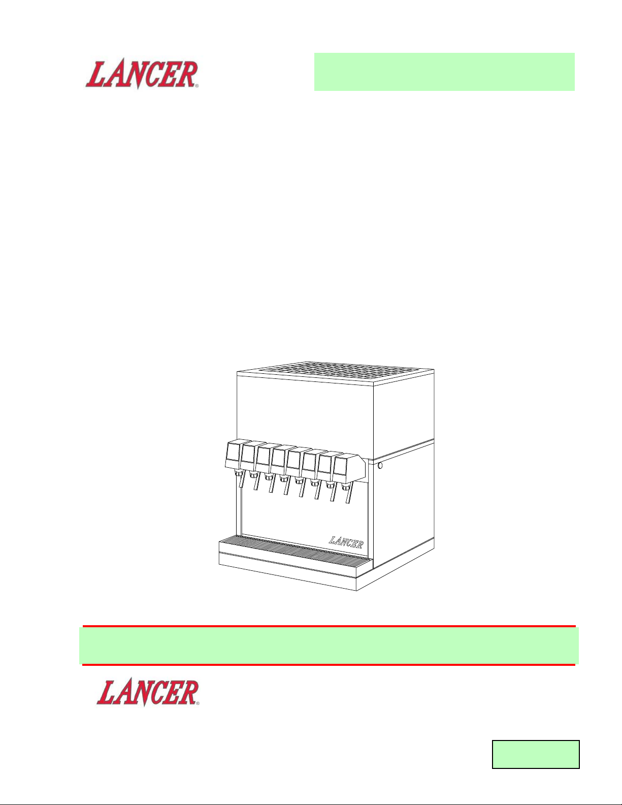
LANCER SERIES 2500
DISPENSERS
REV: 10/06/04
P.N. 28–0089/04
This Manual supersedes Installation and Service Manual, 28-0089/03, dated 01/15/99,
and is being published ONLY on the Lancer Web Site
FAX ENGINEERING: • 210-310-7096
"Lancer" is the registered trademark of Lancer • Copyright — 2004 by Lancer, all rights reserved.
Please refer to the Lancer web site (www.lancercorp.com) for
information relating to Lancer Installation and Service Manuals,
Instruction Sheets, Technical Bulletins, Service Bulletins, etc.
6655 LANCER BLVD. • SAN ANTONIO, TEXAS 78219 USA • (210) 310-7000
FAX SALES
• NORTH AMERICA – 210-310-7245 • INTERNATIONAL SALES – 210-310-7242 • CUSTOMER SERVICE – 210-310-7242 •
• LATIN AMERICA – 210-310-7245 • EUROPE – 32-2-755-2399 • PACIFIC – 61-8-8268-1978 •
®
Page 2

TABLE OF CONTENTS
TABLE OF CONTENTS......................................................................................................................................i
SPECIFICATIONS..............................................................................................................................................ii
1 INSTALLATION ...........................................................................................................................................1
1.1 RECEIVING........................................................................................................................................1
1.2 UNPACKING ......................................................................................................................................1
1.3 SELECTING A COUNTER LOCATION..............................................................................................1
1.4 CONNECTING THE DRAIN...............................................................................................................1
1.5 FILLING UNIT WITH WATER ............................................................................................................1
1.6 CONNECTING TO ELECTRICAL POWER .......................................................................................2
1.7 CONNECTING TO PLAIN WATER SUPPLY.....................................................................................2
1.8 CONNECTING TO CARBONATED WATER SUPPLY.......................................................................3
1.9 CONNECTING TO SYRUP SUPPLY.................................................................................................3
1.10 ADJUSTING WATER FLOW..............................................................................................................3
1.11 ADJUSTING WATER TO SYRUP (RATIO) BRIX ..............................................................................3
2. SCHEDULED MAINTENANCE
2.1 DAILY .................................................................................................................................................4
2.2 WEEKLY.............................................................................................................................................4
2.3 MONTHLY..........................................................................................................................................4
2.4 EVERY SIX MONTHS........................................................................................................................4
2.5 YEARLY..............................................................................................................................................4
3. DISPENSER CLEANING AND SANITIZING..............................................................................................4
3.1 AMBIENT PROCESS.........................................................................................................................4
3.2 VALVES..............................................................................................................................................4
4. TROUBLESHOOTING.................................................................................................................................5
4.1 WATER LEAKAGE AROUND NOZZLE .............................................................................................5
4.2 LEAKAGE BETWEEN UPPER AND LOWER VALVE BODIES.........................................................5
4.3 MISCELLANEOUS LEAKAGE...........................................................................................................5
4.4 INSUFFICIENT WATER FLOW..........................................................................................................5
4.5 INSUFFICIENT SYRUP FLOW..........................................................................................................5
4.6 ERRATIC RATIO ................................................................................................................................5
4.7 NO PRODUCT DISPENSED.............................................................................................................5
4.8 WATER ONLY DISPENSED; NO SYRUP; OR SYRUP ONLY DISPENSED, NO WATER...............6
4.9 VALVE WILL NOT SHUT OFF...........................................................................................................6
4.10 EXCESSIVE FOAMING.....................................................................................................................6
4.11 COMPRESSOR DOES NOT START (NO HUM), BUT CONDENSER FAN MOTOR RUNS............6
4.12 COMPRESSOR STARTS AND CONTINUES TO RUN UNTIL FREEZE UP AND
WILL NOT CUT OFF..........................................................................................................................6
4.13 COMPRESSOR DOES NOT START BUT HUMS .............................................................................6
4.14 COMPRESSOR STARTS BUT DOES NOT SWITCH OFF START WINDING (WILL
RUN FOR ONLY A FEW SECONDS BEFORE INTERNAL OVERLOAD SWITCHES
COMPRESSOR OFF)........................................................................................................................6
4.15 COMPRESSOR STARTS AND RUNS A SHORT TIME BUT SHUTS OFF ON OVERLOAD...........6
4.16 COMPRESSOR AND CONDENSER FAN MOTOR WILL NOT START AFTER
FIVE (5) MINUTE POWER OFF DELAY (LANCER EIBC, EXPORT ONLY).....................................7
4.17 COMPRESSOR AND CONDENSER FAN MOTOR WILL NOT START AFTER
FIVE (5) MINUTE POWER OFF DELAY (LANCER EIBC, USAONLY) ............................................7
4.18 WARM DRINKS ................................................................................................................................7
5. ILLUSTRATIONS, PARTS LISTS, AND WIRING DIAGRAMS ..................................................................8
5.1 2500 REFRIGERATION DECK ASSEMBLY, R-134A, LANCER ELECTRONIC ICE
BANK CONTROL (EIBC), USA ONLY, PN 82-2660 (MANUFACTURED FROM 01/99)................8-9
5.2 2500 REFRIGERATION DECK ASSEMBLY, WITH ELECTRONIC ICE BANK
CONTROL (EIBC), R-134A; PN 82-2049E, 230V/50HZ; PN 82-2103E, 115V/60HZ;
PN 82-2098E, 240V/60HZ...........................................................................................................10-11
5.3 2500 CONTROL HOUSING ASSEMBLY, ELECTRONIC ICE BANK CONTROL(EIBC),
INTERNATIONAL ONLY.............................................................................................................12-13
5.4 2500 CABINET ASSEMBLY........................................................................................................14-15
5.5 2500 WIRING DIAGRAM AND HOUSING CONNECTIONS, LANCER ELECTRONIC
ICE BANK CONTROL USA ONLY...................................................................................................16
5.6 2500 WIRING DIAGRAM, ELECTRONIC ICE BANK CONTROL (EIBC)
INTERNATIONAL ONLY ..................................................................................................................17
5.7 2500 INSTALLATION KITS AND OPTIONALACCESSORIES........................................................18
i
Page 3
ii
SPECIFICATIONS
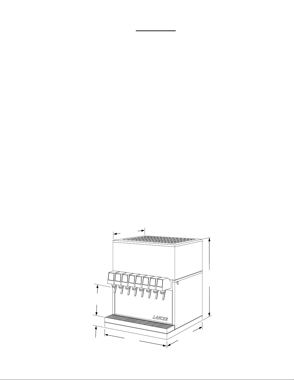
DIMENSIONS
Width 26 inches (660 mm)
Depth 27 1/8 inches (690 mm)
Height (without legs) 31 1/4 inches (790 mm)
WEIGHT
Shipping 257 pounds (117 kg)
Empty 209 pounds (95 kg)
Operating 376 pounds (171 kg)
ICE BANK WEIGHT 50 pounds (23 kg) Nominal
WATER BATH CAPACITY 21 gallons (79 Liters)
COMPRESSOR 3/4 HP Tecumseh, 115V/60Hz
AGITATOR MOTOR 25 WATT, 115V
CONDENSER MOTOR 35 WATT, 115V
ICE BANK CONTROL Lancer Electronic Ice Bank Control (EIBC)
TRANSFORMER Basler, 115V (Primary)/24V (Secondary)
OPTIONAL 230V/50Hz and 240V/60 Hz systems available
DRINK CAPACITY
538 - 12 ounce drinks under 40
o
F (4.4oC) at four (4) drinks per minute with 75oF (23.9oC) ambient inlet
water and syrup.
21 7/8 "
560 mm
31 1/4 "
790 mm
11 1/8 "
280 mm
3 1/2 "
90 mm
26 "
660 mm
®
27 1/8 "
690 mm
Page 4

iii
NOTES
NOTES
Page 5

1. INSTALLATION
1.1 RECEIVING
Each unit is completely tested under operating conditions and thoroughly inspected before
shipment. At time of shipment, the carrier accept s the unit and any claim for damages must be made
with the carrier. Upon receiving units from the delivering carrier, carefully inspect carton for visible
indication of damage. If damage exists, have carrier note same on bill of lading and file a claim with
the carrier.
1.2 UNPACKING
A. Cut band and remove.
B. Remove top portion of carton by lifting up.
C. Remove top inner carton pad and corners.
D. Lift Unit up by plywood shipping base and remove lower portion of carton.
E. Inspect unit for concealed damage and if evident, notify delivering carrier and file a claim against
same.
F. Remove plywood shipping base from unit by moving unit so that one side is off the counter top
or table, allowing access to screws on the bottom of the plywood shipping base.
NOTE
If unit is to be transported, it is advisable to leave unit secured to plywood shipping base.
G. If Unit is to be installed with optional legs, assemble legs to unit by tilting unit. DO NOT LAY
UNIT ON ITS SIDE OR BACK.
H. Remove accessory kit of loose parts from drip tray.
1.3 SELECTING A COUNTER LOCATION
The dispenser is designed to sit on a flat, supported surface capable of supporting a minimum
weight of 400 pounds (182 kg). It may be either counter or leg mounted. Atemplate is furnished to
cut and/or drill the necessary holes for mounting. When the dispenser is to be permanently bolted
to the counter top, seal dispenser base to counter top with a silicone sealant which provides a
smooth and easily cleanable bond to the counter.
NOTE
NSF listed units must be sealed to the counter or have four (4) inch legs installed.
WARNING
FAILURE T O MAINTAIN THE PROPER AIR CLEARANCE WILL CAUSE THE COMPRESSOR TO
OVERHEAT AND WILL RESULT IN PREMATURE COMPRESSOR FAILURE.
Locate dispenser to allow approximately 15 inches (380 mm) of unobstructed space above and
six (6) inches (160 mm) behind the unit for proper air circulation. Air is drawn in through the back
grill and exhausted out of the top grill.
1.4 CONNECTING THE DRAIN
A. Remove cup rest. Lift splash plate up and pull out and down on the bottom to remove.
B. Remove the drip tray from the unit and connect the drain tube to the drain fitting located on the
bottom. Secure drain tube with clamp provided in accessory kit.
C. Route the drain tube to a suitable drain and replace the unit's drip tray.
1.5 FILLING UNIT WITH WATER
A. Remove the bonnet from the unit.
B. Remove the yellow plastic plug from the fill hole.
C. Using a funnel or tube, fill the water bath compartment with water until it flows out of the
overflow tube into the drip tray. Use bottled water where a water problem exists.
D. Replace the yellow plug.
1
Page 6
1.6 CONNECTING TO ELECTRICAL POWER
WARNING
THIS UNIT MUST BE PROPERLY ELECTRICALLY GROUNDED TO AVOID POSSIBLE FATAL
ELECTRICAL SHOCK OR SERIOUS INJURY TO THE OPERATOR. THE POWER CORD IS
PROVIDED WITH A THREE PRONG GROUNDED PLUG. IF A THREE-HOLE GROUNDED
ELECTRICAL OUTLET IS NOT AVAILABLE, USE AN APPROVED METHOD TO GROUND THE
UNIT.
DO NOT USE EXTENSION CORDS WITH THIS UNIT. DO NOT “GANG” TOGETHER WITH
OTHER ELECTRICAL DEVICES ON THE SAME OUTLET.
A. Check the dispenser serial number plate for unit's correct electrical requirements. Do not plug
into electrical outlet unless unit electrical configuration, located on serial plate, agrees with local
available power supply.
B. Route the power supply cord to a grounded electrical outlet of the proper voltage and
amperage rating, and plug in the unit. This will turn on the refrigeration system and allow it to
start cooling while completing the rest of the installation. Approximately three (3) hours are
required to form a full ice bank.
NOTE
Units equipped with an electronic ice bank control contain a five (5) minute delay. Compressor
and fan motor will not begin running until five (5) minutes after the unit is energized.
1.7 CONNECTING TO PLAIN WATER SUPPLY
See Figure 1.
If unit has no plain water circuits, proceed to Section 1.8.
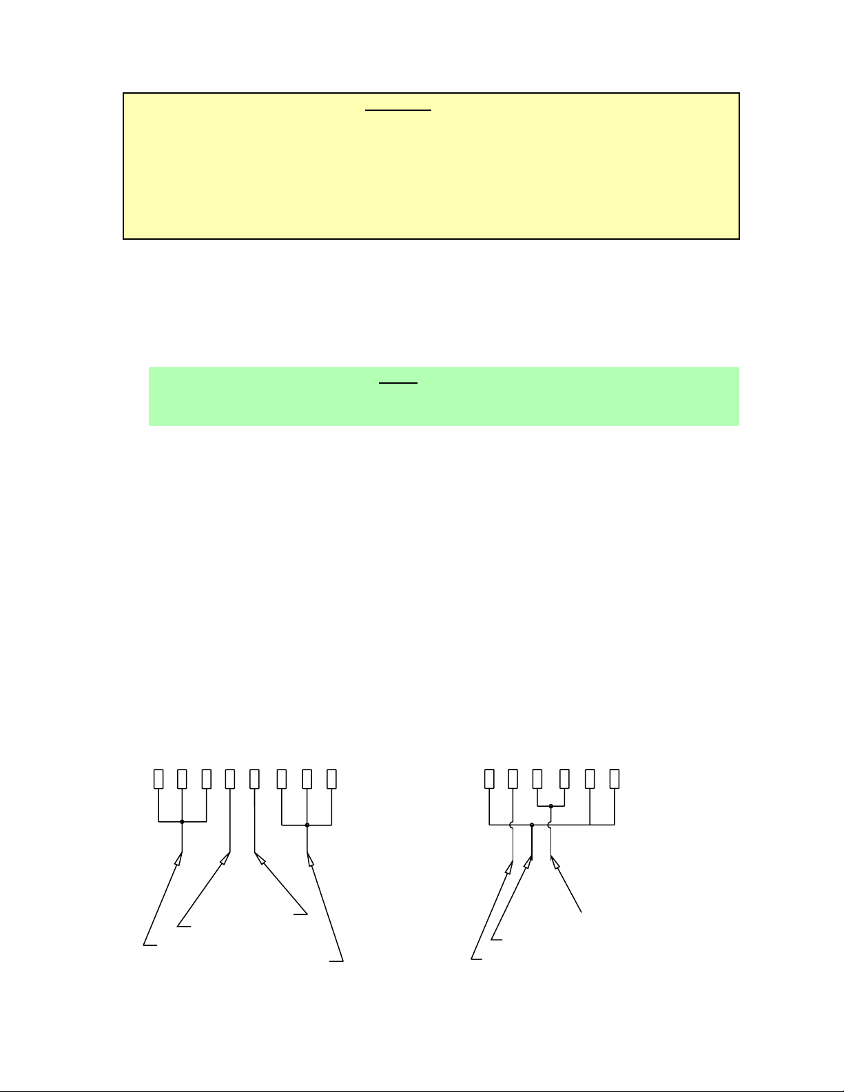
A. Valves 4, 5, and 6 through 8 (on 8 valve units) and valves 3, 4, and 5 (on 6 valve units) have
optional plain water or carbonated water capabilities. Using Figure 1, determine which valves
are to be plumbed with plain water.
B. Using proper beverage tubing and fittings, connect to water source [must be 35 PSI (2.4 bar) or
more].
C. Flush water supply line thoroughly.
D. Route tubing through cutout in counter or through access hole in back of unit.
E. Leave 12 inches (300 mm) of extra tubing length below the counter for servicing and moving
the dispenser.
F. Connect to desired plain water inlet behind splash plate and secure with Oetiker Clamp.
G. Turn on water supply and check for leaks.
H. Actuate each valve until all air is expelled.
2
Plumbing Diagram, Carbonated/Plain Water
Figure 1
8 VALVE
87654321
INLET VALVE 4
INLET VALVE 5
INLET VALVE 6, 7, & 8
INLET VALVE 1, 2, & 3
6 VALVE
6 45 123
INLET VALVE 3 & 4
INLET VALVE 1, 2, & 6
INLET VALVE 5
Page 7
3
1.8 CONNECTING TO CARBONATED WATER SUPPLY
See Figure 1.
A. Install carbonator per manufacturer’s instructions.
B. Using proper beverage tubing and fittings, connect to carbonator tank outlets.
C. Route tubing through cutout in counter or through access hole in back of unit.
D. Leave 12 inches (300 mm) of extra tubing length below the counter for servicing and moving
the dispenser.
E. Connect to soda inlets behind splash plate and secure with Oetiker Clamps.
F. Fill with water and pressurize carbonation system per manufacturer’s instructions.
G. Actuate each valve until a smooth flow of carbonated water is obtained.
H. Check for leaks.
1.9 CONNECTING TO SYRUP SUPPLY
A. Using proper beverage tubing and fittings, connect to syrup inlets and secure with Oetiker
Clamps.
B. Mark syrup tube assemblies with product ID tape.
C. Route tubing through cutout in counter or through access hole in back of unit.
D. Leave 12 inches (300 mm) of extra tubing length below the counter for servicing and moving
the dispenser.
E. Connect to appropriate five (5) gallon syrup containers or bag-in-box system.
F. Pressurize system.
G. Actuate each valve until product is observed.
H. Check for leaks.
)
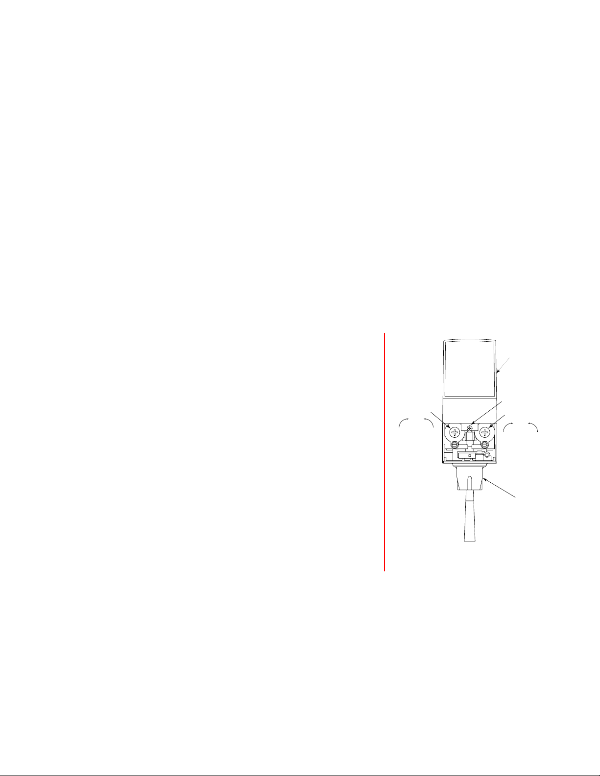
Typical Valve Adjustment
Figure 2
1.10 ADJUSTING WATER FLOW
A. The water flow can be adjusted to either1.25 oz/sec
(37 ml/sec) or 2.50 oz/sec (74 ml/sec) on all dispensing
valves using the following procedure.
B. The refrigeration unit should have been running for at
least one hour before you attempt to brix the valves.
The drink temperature should be no higher than 40
o
F
(4.4oC) when the brix is set. This is best done after the
unit has made an ice bank.
C. Slide up ID panel until flow controls are exposed.
D. Remove nozzle by twisting counter clockwise and
pulling down.
E. Remove diffuser by pulling down.
F. Install Lancer (yellow) syrup separator (PN 54-0031) in
place of nozzle.
G. Activate dispensing valve to fill separator syrup tube.
H. Hold a Lancer brix cup under the syrup separator and
dispense water and syrup into cup for four (4) seconds.
Divide number of ounces (ml) of water in cup by four (4)
to determine water flow rate per second.
I. To obtain the proper flow, use a screwdriver to adjust water flow control (see Figure 2).
J. Repeat process for each valve.
1.11 ADJUSTING WATER TO SYRUP (RATIO) BRIX
A. Hold the Lancer brix cup under the syrup separator and activate valve. Check brix.
B. To obtain the proper brix, use screwdriver to adjust syrup flow control (see Figure 2).
C. Remove the syrup separator.
D. Install diffuser and nozzle.
E. Slide down ID panel.
F. Repeat process for each valve.
FLOW CONTROL
WATER
DecreaseIncrease
I.D. PANEL
(Shown in
open position)
COVER SCREW
FLOW CONTROL
SYRUP
DecreaseIncrease
NOZZLE (WITH
DIFFUSER INSIDE
Page 8

4
2. SCHEDULED MAINTENANCE
2.1 DAILY
A. Remove the nozzle and diffuser from each valve and rinse well in warm water. Do NOT use
soap or detergent. This will cause foaming and off taste in finished product.
B. Remove the cup rest and wash in warm soapy water.
C. Pour warm soapy water into the drip tray and wipe with a clean cloth.
D. With a clean cloth and warm water, wipe off all of the unit's exterior surfaces. DO NOT USE
ABRASIVE SOAPS OR STRONG DETERGENTS.
E. Replace the cup rest, valve diffusers, and valve nozzles.
2.2 WEEKLY
A. Taste each product for off tastes and/or brix changes.
B. Remove the bonnet and check the level of water in the water bath. Replenish as required, and
replace the bonnet.
2.3 MONTHLY
A. Unplug the dispenser from power source.
B. Remove the bonnet and clean the dirt from the condenser using a soft brush.
C. Replace the bonnet and plug in the unit.
2.4 EVERY SIX MONTHS
A. Clean and sanitize the unit using the appropriate procedures outlined in Section 3 of this
manual.
2.5 YEARLY
A Clean water bath interior, including evaporator coils and refrigeration components.
B. Clean the entire exterior of the unit.
C. Sanitize syrup lines.
3. DISPENSER CLEANING AND SANITIZING
3.1 AMBIENT PROCESS
A. The ambient process is the most common method for cleaning and sanitizing dispenser
equipment. The detergent should be caustic-based and the sanitizer should be low pH (7.0)
chloride solution.
B. Disconnect syrup containers and remove product from tubing by purging with carbon dioxide.
C. Rinse the lines and fittings with clean, room temperature water to remove all traces of residual
product.
D. Fill lines with a caustic-based (low-sudsing, non-perfumed, and easily rinsed) detergent solu-
tion. The solution should be prepared in accordance with the manufacturer’s recommendations,
but should be at least two (2) percent sodium hydroxide. Make sure the lines are completely
filled and allow to stand for at least ten (10) minutes.
E. Flush the detergent solution from the lines with clean water. Continue rinsing until testing with
phenolpthalein shows that the rinse water is free of residual detergent.
F. Fill the lines with a low pH (7.0) chlorine solution containing at least 50 parts per million (PPM)
(50 mg/L) available chlorine. Make sure that lines are completely filled and allow to stand for
ten (10) minutes.
G. Reconnect syrup containers and ready Unit for operation.
H. Draw drinks to refill lines and flush the chlorine solution from the dispenser.
I. Taste the beverage to verify that there is no off taste.
3.2 VALVES
A. Valves may be cleaned and sanitized in the same manner
1. Remove cover and disconnect power so not to activate the valve while cleaning. Remove
nozzle and diffuser. Wash these parts in cleaning solution, then immerse them in a bath of
sanitizing solution for 15 minutes.
Page 9

2. Visually inspect around nozzle area for syrup residue. This area may be cleaned with warm
water and cloth or with the nozzle brush supplied. Wipe off dispensing lever.
3. Wearing sanitary gloves, remove, drain and air dry the nozzle and diffuser.
4. Wearing sanitary gloves, replace diffuser and twist nozzle into place.
5. Connect power and replace cover. Valve is ready for operation.
4. TROUBLESHOOTING
TROUBLE
CAUSE REMEDY
4.1 Water leakage around A. Damaged or improperly A. If damaged, replace. If improperly
nozzle. installed o-ring above diffuser. installed, adjust.
4.2 Leakage between upper A. Gap between upper and lower A. Tighten all six (6) retaining screws.
and lower valve bodies. valve bodies.
B. Worn or damaged paddle arm B. Replace paddle arm assemblies.
assemblies.
4.3 Miscellaneous leakage. A. Gap between parts. A. Tighten appropriate retaining screws.
B. Damaged or improperly installed B. Replace or adjust appropriate o-rings.
o-rings.
4.4 Insufficient water flow. A. Insufficient incoming supply water A. Verify incoming supply water pressure
pressure. is a minimum of 35 PSI (2.4 bar).
B. Shutoff on mounting block not B. Open shutoff fully.
fully open.
C. Foreign debris in water flow C. Remove water flow control from upper
control. body and clean out any foreign material
to ensure smooth free spool
movement.
4.5 Insufficient syrup flow. A. Insufficient CO
2 pressure to A. Adjust CO2 pressure to 80 PSI
BIB Pumps. (5.5 bar) [minimum 70 PSI (4.8 bar)]
for BIB pumps.
B. Shutoff on mounting block not B. Open shutoff fully.
fully open.
C. Foreign debris in syrup flow C. Remove syrup flow control from upper
control. body and clean out any foreign material
to ensure smooth free spool
movement.
4.6 Erratic ratio. A. Incoming water and/or syrup A. Check pressure and adjust.
supply not at minimum flowing
pressure.
B. Foreign debris in water and/or B. Remove flow controls from upper body
syrup flow controls. and clean out any foreign material to
ensure smooth free spool movement.
4.7 No product dispensed. A. Water and syrup shutoffs on A. Open shutoffs fully.
mounting block not fully open.
B. The key switch on an electric B. Turn key switch to ON position.
valve is in the OFF position.
C. Cup lever arm or ID panel C. Repair.
actuator on electric valve is not
actuating the switch.
D. Electric current not reaching D. Check electric current supplied to
Valve. valve. If current is adequate, check
solenoid coil and switch, and replace if
necessary.
E. Improper or inadequate water E. Remove valve from mounting block and
or syrup supply. open shutoffs slightly and check water
and syrup flow. If no flow, check
dispenser for freeze-up or other
problems.
F. Tripped Circuit Breaker on F. Find cause of short and correct. Then
24 volt transformer. reset transformer.
5
Page 10

4.8 Water only dispensed; A. Water or syrup shutoff on A. Open shutoff fully.
no syrup; or syrup only mounting block not fully open.
dispensed, no water. B. Improper or inadequate water B. Remove valve from mounting block,
or syrup flow. open shutoffs slightly and check water
and syrup flow. If no flow, check
dispenser for freeze-up or other
problems. Ensure BIB connection is
engaged.
C. Kinked line. C. Remove kink or replace line.
4.9 Valve will not shut off. A. Cup lever may be sticking or A. Correct or replace lever.
binding.
B. Switch not actuating freely. B. Check switch for free actuation.
C. Solenoid armature not returning C. Replace defective armature or spring.
to bottom position.
4.10 Excessive foaming. A. Incoming water or syrup A. Correct prior to dispenser.
temperature too high. Consider larger dispenser or precooler.
B. Water flow rate too high. B. Readjust and reset ratio. Refer to
Sections 1.10 and 1.11.
C. Nozzle and diffuser not properly C. Remove and reinstall properly.
installed.
D. Nozzle and diffuser not clean. D. Remove and clean.
E. Air in BIB lines. E. Bleed air from BIB lines.
F. Poor quality ice. F. Check quality of ice used in drink.
G. High beverage temperature. G. Check refrigeration system.
4.11 Compressor does not start A. Compressor relay or overload A. Replace compressor relay or overload.
(no hum), but condenser malfunctioning.
fan motor runs. B. Inadequate voltage. B. Measure voltage across common and
run terminal on compressor. Voltage
must not drop below 90% of rated
voltage.
C. Incorrect wiring. C. Refer to wiring diagram and correct.
D. Compressor malfunctioning. D. Replace compressor.
4.12 Compressor starts and A. Ice bank control failure. A. Replace ice bank control.
continues to run until freeze B. Incorrect wiring. B. Refer to wiring diagram and correct.
up and will not cut off. C. Probe shorted. C. Check spring for foreign material or
damage.
4.13 Compressor does not start A. Inadequate voltage. A. Measure voltage across common and
but hums. run terminal on compressor. Voltage
must not drop below 90% of rated
voltage.
B. Incorrect wiring. B. Refer to wiring diagram and correct.
C. Starting relay malfunctioning. C. Replace starting relay. Be sure to use
correct relay. Failure to use correct
relay will cause compressor failure.
D. Compressor malfunctioning. D. Replace compressor.
4.14 Compressor starts but does A. Inadequate voltage. A. Measure voltage across common and
not switch off start winding run terminal on compressor.
(will run for only a few B. Incorrect wiring. B. Refer to wiring diagram and correct.
seconds before internal C. Starting relay malfunctioning. C. Replace starting relay. Be sure to use
overload switches correct relay. Failure to use correct
compressor off). relay will cause compressor failure.
4.15 Compressor starts and runs A. Dirty condenser. A. Clean the condenser.
a short time but shuts off B. Insufficient or blocked air flow. B. Remove all obstructions and allow for
on overload. minimum clearances of 8 inches
(203 mm) over top.
C. Inadequate voltage. C. Measure voltage across common and
run terminal on compressor. Voltage
must not drop below 90% of rated
voltage.
Section 4.15 continued on next page
6
TROUBLE
CAUSE REMEDY
Page 11

Section 4.15 continued from previous page
D. Incorrect wiring. D. Refer to wiring diagram and correct.
E. Defective condenser fan motor. E. Replace condenser fan motor.
F. Refrigerant leak. F. Repair and recharge.
G. Compressor malfunctioning. G. Replace compressor.
4.16 Compressor and A. Fuse blown on EIBC PCB. A. Replace fuse on EIBC PCB.
Condenser Fan Motor will B. Relay will not turn on compressor. B. Failed relay. Replace Control Board.
not start after five (5) C. Transformer tripped. C. Reset transformer.
minute Power Off delay D. Probe unplugged. D. Check probe connections at PCB.
(Lancer EIBC Export
only).
4.17 Compressor and A. Improper Wiring. A. Check Power Indicator Lamp;
Condenser Fan Motor will check wiring per Wiring Diagram.
not start after five (5) B. Probe unplugged. B. Check Probe connection at PCB.
minute Power Off delay C. Damaged electronics. C. Replace Control.
(Lancer EIBC, USA Only).
4.18 Warm drinks. A. Restricted airflow. A Check clearances around sides, top,
and inlet of unit. Remove objects
blocking airflow through grill.
B. Dispenser connected to hot water B. Switch to cold water supply.
supply.
C. Refrigeration system not running. C. Refer to Sections 4.11 - 4.16.
D. Refrigerant leak. D. Repair and recharge.
E. Condenser fan motor not working. E. Replace condenser fan motor.
F. Dirty condenser. F. Clean condenser.
G. Dispenser capacity exceeded. G. Add pre-cooler.
NOTES
TROUBLE CAUSE REMEDY
7
Page 12

8
5. ILLUSTRATIONS, PARTS LISTS, AND WIRING DIAGRAMS
5.1 2500 REFRIGERATION DECK ASSEMBLY, R-134A, LANCER ELECTRONIC ICE BANK
CONTROL (EIBC), USA ONLY, PN 82-2669
(MANUFACTURED FROM 01/99)
TO
BOX
BL
JUNCTION
45
9
10
6
33
31
46
4
38
TO RELAY
14
17
TO OVERLOAD
23
13
12
BL/W
BL
BL/W
17
20
27
4B
4C
27G
27F
27D
41
30
4A
27A
40
27C
17
35
34
27E
27B
11
36
24
44
5
43
- IMPORTANT -
WATER BATH FILL HOLE
FILL WATER BATH UNTIL
WATER FLOWS FROM
TANK OVERFLOW TUBE.
8
42
7
8
17
21
28C
37
17
3
29
28D
22
17
28G
28A
28F
28
28B
28E
15
31
16
19
17
26
2
18
1
39
25
32
Page 13

9
5.1 2500 REFRIGERATION DECK ASSEMBLY, R-134A, LANCER ELECTRONIC ICE BANK
CONTROL (EIBC), USA ONLY, PN 82-2669 (CONTINUED)
(MANUFACTURED FROM 01/99)
ITEM PART NO. DESCRIPTION
1 23-0986 Condenser
2 51-0349 Shroud Assy
3 25-0047 Transformer, 115V/60Hz
4 83-0101 Compressor, 115V/60Hz
4A 12-0233 Start Capacitor, 115V/60Hz
4B 12-0227 Overload, 115V/60 Hz
4C 12-0232 Relay, 115V/60Hz
- - - - - - - - Refrigerant, R134A Only,
15.5 Ounces
5 23-1205 Evaporator Coil Assy
6 82-0675 Compressor Deck Assy
7 04-0032 Nut, 1/4 - 20
8 04-0063 Washer, 0.260 ID x 0.687 OD, SS
9 07-0268 Deck Handle
10 04-0260 Screw, 10 - 16 x 0.625
11 04-0538 Fill Hole Plug
12 02-0114 Grommet, Compressor
13 04-0537 Washer, Compressor
14 03-0150 Retainer Clip, Compressor
15 23-0999 Dryer/Capillary Tube Assy
16 51-5400 Accumulator
17 04-0504 Screw, 8 -18 x 0.375
18 47-2064 Tube, High Side
19 50-0105 Accumulator Insulator Boot
20 50-0106 Insulation, Low Side
21 50-0107 Insulation, Evaporator Outlet
22 50-0108 Insulation, Evaporator Inlet
23 52-1882 Electronic Ice Bank Control
(EIBC)
24 03-0049 Cord Clip
25 52-0100 Power, Junction Assy
26 06-0031/01 Wiring Diagram, 2500
27 52-1259 Agitator Motor Assy, 115V/60Hz
27A 91-0083 Motor, Agit ator, 115V/60Hz
27B 05-0502 Propeller, Agit ator
27C 02-0032 Washer, Rubber, 1.000 OD
27D 30-5113/01 Agitator Motor Bracket
27E 04-0059 Screw, 8 - 36 x 0.375
27F 05-0424/01 Agitator Fan
27G 06-0633 Label, 115V/60Hz, 25W
28 52-0740 Fan Motor Assy, 115V/60Hz
28A 91-0017 Fan Motor, 115V/60Hz
28B 07-0257 Fan Blade
28C 30-0043 Bracket, Fan Motor
28D 04-0059 Screw, 8 - 36 x 0.375
28E 04-0060 Nut, Fan Blade
28F 02-0413 Silencer, Fan Blade
28G 06-0667 Label, 115V/60Hz, 35W
29 11-0118 Connector, Ground
30 47-2033/01 Tube, Suction
31 47-0344 Tube, Process
32 04-0070 Screw, 10 - 24 x 1.312
33 01-1713 Reducer, Fitting, Elbow
34 52-0878 Wire, Transformer Lead, Primary
35 52-0879 Wire, Transformer Lead, Primary
36 06-0856/01 Fill Hole Label
37 02-0040 Seal, Extrusion
38 06-0663 Label, 115V/60Hz, 3/4 HP
39 21-0085 Power Cord, USA
40 52-1504 Wire Assy, Secondary, White
41 52-1505 Wire Assy, Secondary, Black
42 02-0041 Seal
43 52-1897 Probe Assy
44 04-0394 Screw, 6 - 32 x 0.500, PHP, SS
45 52-1827 Harness Assy, EIBC
46 13-0059 Bushing, Heyco
ITEM PART NO. DESCRIPTION
Page 14

10
5.2 2500 REFRIGERATION DECK ASSEMBLY WITH ELECTRONIC ICE BANK CONTROL (EIBC),
R-134A; PN 82-2049E, 230V/50Hz; PN 82-2103E, 115V/60Hz; PN 82-2098E, 240V/60Hz
(INTERNATIONAL ONLY)
33
17
34
23
17
31
38
14
4
37
4B
32
12
10
6
9
11
24
27
17
27F
27D
27A
20
4C
27G
17
30
4A
27C
3
27E
27B
16
13
7
17
WATER BATH FILL HOLE
FILL WATER BATH UNTIL
-IMPORTANT-
WATER FLOWS FROM
TANK OVERFLOW TUBE.
35
25
26
21
36
8
17
28C
5
29
28A
22
28D
28G
28F
17
28B
19
28
28E
15
17
2
18
31
1
Page 15

11
ITEM PART NO. DESCRIPTION
1 23-0986 Condenser
2 51-0349 Shroud Assy
3 25-0047 Transformer, 115V/60Hz
- 25-0048 Transformer, 230V/50-60Hz
4 83-0101 Compressor, 115V/60Hz
- 83-0102 Compressor, 230V/50Hz
- 83-0103 Compressor, 240V/60Hz
4A 12-0233 Start Capacitor, 115V/60Hz
- 12-0235 Start Capacitor, 230V/50Hz
- 12-0246 Start Capacitor, 240V/60Hz
4B 12-0227 Overload, 115V/60Hz
- 12-0045 Overload, 230V/50Hz
- 12-0043 Overload, 240V/60Hz
4C 12-0232 Relay, 115V/60Hz
- 12-0236 Relay, 230V/50Hz
- 12-0247 Relay, 240V/60Hz
- - - - - - - Refrigerant, R134A Only; 115V/60Hz
and 240V/60Hz, 15.50 Ounces;
230V/50Hz, 15.75 Ounces
5 23-1205 Evaporator Coil Assy
6 82-0675 Compressor Deck Assy
7 04-0032 Nut, 1/4 - 20
8 04-0063 Washer, 0.260 ID x 0.687 OD, SS
9 07-0268 Deck Handle
10 04-0260 Screw, 10 - 16 x 0.625
11 04-0538 Fill Hole Plug
12 02-0114 Grommet, Compressor
13 04-0537 Washer, Compressor
14 03-0150 Retainer Clip, Compressor
15 23-0999 Dryer/Capillary Tube Assy
16 51-5400 Accumulator
17 04-0504 Screw, 8 -18 x 0.375
18 47-2064 Tube, High Side
19 50-0105 Accumulator Insulator Boot
20 50-0106 Insulation, Low Side
21 50-0107 Insulation, Evaporator Outlet
22 50-0108 Insulation, Evaporator Inlet
23 52-2026 Control Housing Assy, EIBC
24 03-0049 Cord Clip
25 52-1773 Probe Assy, EIBC
26 04-0394 Screw, 6 -32 x 0.500
27 52-1259 Agitator Motor Assy, 115V/60Hz
- 52-1118 Agitator Motor Assy,
220-240V/50-60Hz
27A 91-0083 Motor, Agitator , 115V/60Hz
- 91-0086 Motor, Agitator, 230V/50Hz and
240V/60Hz
27B 05-0502 Propeller, Agitator
27C 02-0032 Washer, Rubber, 1.000 OD
27D 30-5113/01 Agitator Motor Bracket
27E 04-0059 Screw, 8 - 36 x 0.375
27F 05-0424/01 Agitator Fan
27G 06-0633 Label, 115V/60Hz, 25W
- 06-0634 Label, 230V/50-60Hz, 25W
28 52-0740 Fan Motor Assy, 115V/60Hz
- 52-0741 Fan Motor Assy, 240V/60Hz
- 52-0742 Fan Motor Assy, 230V/50Hz
28A 91-0017 Fan Motor, 115V/60Hz
- 91-0018 Fan Motor, 230V/50Hz
- 91-0019 Fan Motor, 240V/60Hz
28B 07-0257 Fan Blade
28C 30-0043 Bracket, Fan Motor
28D 04-0059 Screw, 8 - 36 x 0.375
28E 04-0060 Nut, Fan Blade
28F 02-0413 Silencer, Fan Blade
28G 06-0667 Label, 115V/60Hz, 35W
- 06-0668 Label, 230V/50Hz, 35W
- 06-0669 Label, 240V/60Hz, 35W
29 11-0118 Connector, Ground
30 47-2033/01 Tube, Suction
31 47-0344 Tube, Process
32 01-1713 Reducer, Fitting, Elbow
33 52-2027 Harness Assy, EIBC Ground
34 06-1542 Wiring Diagram, Label, EIBC
35 06-0856/01 Fill Hole Label
36 02-0040 Seal, Extrusion
37 06-0663 Label, 115V/60Hz, 3/4HP
- 06-0664 Label, 230V/50Hz, 3/4HP
- 06-0665 Label, 240V/60Hz, 3/4HP
38 02-0041 Seal
5.2 2500 REFRIGERATION DECK ASSEMBLY WITH ELECTRONIC ICE BANK CONTROL (EIBC),
R-134A; PN 82-2049E, 230V/50Hz; PN 82-2103E, 115V/60Hz; PN 82-2098E, 240V/60Hz
(CONTINUED)
(INTERNATIONAL ONLY)
ITEM PART NO. DESCRIPTION
Page 16

20
12
5.3 2500 CONTROL HOUSING ASSEMBLY, ELECTRONIC ICE BANK CONTROL (EIBC),
INTERNATIONAL ONLY
7
RIGHT SIDE VIEW
19
3
3
2
4
5
17
TERM1
1
J4
J3J2
J1
TERM2
TERM3
TERM4
9
23
11 10
4
12
5678
16 15 14 13
8
7
GROUND WIRES FROM POWER CORD
AND OPTIONAL MERCHANDISER TO
BE FASTENED TO GROUND STUD ON
COMPRESSOR DECK INSIDE OF
CONTROL HOUSING.
FRONT VIEW
9
1
8
10
BROWN WIRE FROM
POWER CORD ASSY
BLACK WIRE TO
TERMINAL BLOCK #12
11
12
13
14
16
6
TERMINAL PIN #3
WHITE WIRE TO 13
TERMINAL PIN #1
TERMINAL PIN #2
GREEN W/YELLOW
STRIPE WIRE TO
GROUND STUD
BLACK WIRE TO 11
16
LEFT SIDE VIEW
Page 17

13
5.3 2500 CONTROL HOUSING ASSEMBLY, ELECTRONIC ICE BANK CONTROL (EIBC)
INTERNATIONAL ONLY (CONTINUED)
ITEM PART NO. DESCRIPTION
1 30-7012 Housing, Control
2 52-1423 PCB Assy
3 13-0047 Stand Off
4 12-0190 Block, Terminal
5 04-0477 Screw, 8 - 32, ROLOK
6 13-0059 Bushing
7 13-0028 Strain Relief
8 52-2057 Power Cord Assy
9 - - - - - - - Not Applicable
10 - - - - - - - Not Applicable
1 1 52-2021 Lead Assy , Transformer,
Primary, #1
12 52-2022 Lead Assy , Transformer,
Primary, #2
13 52-2023 Lead Assy, Compressor, #1
14 52-2024 Lead Assy, Compressor, #2
15 52-2061 Lead Assy , EIBC
16 52-1210 Harness Assy , Optional
Merchandiser
17 11-0186 Jumper
18 52-1058 Harness, Transformer, Secondary
19 30-7015 Cover, EIBC, Box Without Kill
Switch
20 04-0504 Screw, 8 -18 x 0.375
5.3.A CONTROL HOUSING ASSEMBLY, EIBC,
PN 52-2026, WITHOUT KILL SWITCH
WIRING CONNECTION CHART
PART NO. DESCRIPTION TERMINAL
52-1219 Power Cord (BLU) 15
with Kill Power Cord (GRN/YEL) Ground Stud
Switch Power Cord (BRN) Kill Switch (A-A)
52-1218 Power Cord (BLU) 15
without Power Cord (GRN/YEL) Ground Stud
Kill Switch Power Cord (BRN) 12
52-2038 Lead, Kill Switch, 12
14 GA (BLK)
52-2021 Lead,Trans, Pri #1 (BLK) 3
52-2022 Lead,Trans, Pri #2 (BLK/WHT) 3
52-2058 Harness,Trans, Sec (BLK) J1
Harness,Trans, Sec (WHT)
52-2023 Lead,Comp, #1 (BLK) Terminal 1
52-2024 Lead,Comp, #2 (BLK/WHT) 6
52-1773 IBC Probe Assy J2
52-1259 Lead, Agitator Motor (BLK) 10
52-0742 Lead, Agitator Motor 14
(BLK-RIDGED)
Harness, Optional 11
Merchandiser (BLK)
52-1210 Harness, Optional Ground Stud
Merchandiser (GRN/YEL)
Harness, Optional 13
Merchandiser (WHT)
52-2061 Lead Assy, EIBC, 2500 Terminal 2 to 1
Page 18

5.4 2500 CABINET ASSEMBLY
14
29
18
21
15
14
30
13
28
33
8
7
6
4
34
16
35
37
36
5
12
38
6
11
3
2
1
19
20
22
16
23
24
15
17
16
32
31
25
26
10
9
27
Page 19

ITEM PART NO. DESCRIPTION
1 30-0643/01 Wrapper, External
2 51-0547 Trim, Gray
3 04-0067 Rivet
4 50-0175 Insulation, 1/2 inch
5 50-0180 Insulation, 1/2 inch
6 50-0102 Insulation, 1/8 inch
7 50-0184 Insulation, 1/8 inch
8 04-0082 Nut, Hex, 10 - 24, SS
9 30-0612 Back Plate
10 04-0477 Screw, 8 - 32 x 0.375 inch
11 42-0013 Tank, Foamed
12 04-0074 Nut, Clip, 10 - 24
13 30-0649/02 Front Support Plate
14 03-0036 Clip, Drain Tube
15 04-0077 Screw, #4 x 1/4 inch
16 04-0061 Screw, #8 x 1/2 inch
17 03-0115 Clip, Overflow Tube
18 04-0443 Screw, 10 - 24 x 0.375
19 13-0005 Bushing, Strain Relief
20 11-0015 Connector Housing
21 23-0391 Faucet Plate, 8-Valve
-- 23-0605 Faucet Plate, 6-Valve
-- 30-6702 Faucet Plate, 6-Valve, Premix
-- 30-6703 Faucet Plate Stiffener, 6-Valve,
Premix
22 30-6640 Splash Plate
23 30-0535 Cup Rest
24 23-0306 Drip Tray
25 12-0097 Key Lock Switch
26 52-0893/01 Harness Assy, 8-Valve
-- 52-1214 Harness Assy, 6-Valve
27 51-0582 Base Assy
28 82-1120 Insulator Plate Assy
29 23-0443/02 Bonnet Assy (Specify Graphics)
30 30-5314 Shim Plate
31 04-1012 Rivet, Splash Plate Spacer
32 01-1705 Spacer, Splash Plate
33 30-5599/02 Retainer, Cage, 2500
34 30-5143 Clip, Drain
35 01-0450 Tube Support
36 08-0190 Drain Tube
37 01-1483 Elbow Drain Assy
38 04-0072 Rivet
5.4 2500 CABINET ASSEMBLY (CONTINUED)
15
NOTE: Cage Assembly Part Numbers are:
23-1232/01 6-Valve, 3-2-1 Manifold,
3/8 inch Syrup Inlets
23-1236/01 8-Valve, 3-1-1-3 Manifold,
3/8 inch Syrup Inlets
23-0919 4-Circuit Chiller
23-0798/01 9-Circuit Chiller
23-1103 6-Valve Premix
ITEM PART NO. DESCRIPTION
Page 20

5.5 2500 WIRING DIAGRAM AND HOUSING CONNECTIONS, LANCER ELECTRONIC ICE BANK
CONTROL, USA ONLY
16
LABEL, WIRING DIAGRAM, CED, PN 06-0031/01
CONTROL HOUSING CONNECTIONS
IMPORTANT
WHEN STARTING UNIT OR IF CURRENT IS INTERRUPTED, THERE IS
A FIVE (5) MINUTE DELAY BEFORE THE COMPRESSOR/FAN STARTS.
OVERLOAD
GREEN
BLACK
WHITE
120 AC
AGITATOR
MOTOR
24V LEADS
TRANSFORMER
JCT.
LANCER
ICE
BANK
CONTROL
FAN
MOTOR
COMPRESSOR
RELAY
PROBE
C
M
L
LABEL, WIRING
500 / 2500, CED
06-0031/01
S
M
S
EIBC PROBE CONNECTION
POWER INDICATOR LAMP
HOT OUT
HOT IN
POWER
CONNECTIONS
Page 21

5.6 2500 WIRING DIAGRAM, ELECTRONIC ICE BANK CONTROL (EIBC), INTERNATIONAL ONLY
17
IMPORTANT
WHEN STARTING UNIT OR IF CURRENT IS INTERRUPTED, THERE IS
A FIVE (5) MINUTE DELAY BEFORE THE COMPRESSOR/FAN STARTS.
V
A
L
V
E
S
KEY
SWITCH
S1
S2
S3
S4
S5
S6
S7
S8
B
B
B
B
B
B
B
POWER
CORD
B
B
W
W
W
W
W
W
W
W
BLGBR
B
W
J1
LINE
24 V
B/WB
8765 43 21
BL WB
BBR
RIBBED
KILL
USA
ONLY
BLK
B
AGITATOR
MOTOR
COMPRESSOR
SWITCH
TB1
IN OUT OUTIN
B
J2
PCB,IBC
TERM3TERM4
B
BBB/W
B
J3
TERM1
TERM2
BB
BB/W
910111213141516
B/W
B
J4
W
W OR R
B
G
1
G
3
RIBBED BLK
PLAIN BLK
ICE
PROBE
G
OPTIONAL
B
G
W
MERCHANDISER
FAN
MOTOR
SYM.
DESCRIPTION
CHASSIS GROUND
CONTROL BOX
CHAMFER PIN 1
fi
LABEL,
WIRING DIAGRAM
06-1542
Page 22

5.7 INSTALLATION KITS AND OPTIONAL ACCESSORIES
PART NUMBER DESCRIPTION
• 82-1796 BIB Installation Kit - For 3/8 Inch Syrup Inlets
• 82-0221-06 FIGAL Installation Kit - 6 Valve - For 1/4 Inch Syrup Inlets
• 82-0221-08 FIGAL Installation Kit - 8 Valve - For 1/4 Inch Syrup Inlets
• 82-2613-06 FIGAL Installation Kit - 6 Valve - For 3/8 Inch Syrup Inlets
• 82-2613-08 FIGAL Installation Kit - 8 Valve - For 3/8 Inch Syrup Inlets
• 82-0344 Leg Kit
• 82-2139 EIBC Retrofit Kit - International Only
• 82-2572 ELS Marquee Kit - Graphics Included
•
82-1802 24VAC Lighted Marquee (Graphics Ordered Separately)
•
Marquee Graphics for PN 82-1802 Only
• 06-1790 Coca-Cola Dynamic Ribbon, Screened
• 06-1789 Coca-Cola Three Cup, “Taste Real Refreshment”, Duratrans
18
Page 23

(Continued from previous page)
PromoVen, S.A. - Argentina
Contact: Rafael Mendoza
Juncal 858 - Piso 3 Depto. “L”
(1062) Buenos Aires
Argentina
Phone: (54.11)4394.7654
FAX: (54.11)4394.1193
e-mail: promoven@customw.com.ar
Bras Sulamericana LTDA. - Brasil
Contact: Fabio Queiroz
Rua. Dr. Ladislau Retti, 1400
Parque Alexandre
Cotia Sao Paulo - Brasil
CEP: 06714-150
Phone: 55-11-4612-1122
FAX: 55-11-4612-2219
e-mail: fabio.queiroz@bras.com.br
Lancer Chile Ltda. - Chile
Contact: Heriberto Concha
Vicuna Mackenna 3019, San Joaquin
Santiago, Chile
Phone: 56-2-552-1657
FAX: 56-2-552-1961
e-mail: chocha@lancer.tie.cl
Lancer Pacific
International Sales
6655 Lancer Blvd.
San Antonio, TX 78219
Phone: (210) 310-7000
FAX: (210) 310-7242
1-800-729-1500
e-mail: asia@lancercorp.com
Australia
Lancer Pacific Pty Ltd
5 Toogood Avenue
Beverley 5009
South Australia
Phone: 61-8-8268-1388
FAX: 61-8-8268-1978
e-mail: ian-lunniss@lancer-pacific.com.au
(General Manager, Lancer Pacific)
steve-sotiriou@lancer-pacific.com.au
(for Fountain)
fiore-alvaro@lancer-pacific.com.au
(for Beer)
Lancer Pacific Pty Ltd
7 Slough Avenue
Silverwater 2128
New South Wales
Australia
Phone: 61-2-9648-6840
FAX: 61-2-9648-6850
e-mail: neild-mcintosh@lancer-
pacific.com.au
(Managing Director)
john-frize@lancer-pacific.com.au
(NSW State Manager)
Lancer Pacific Pty Ltd
55 Keele Street
Collingwood 3066
Victoria
Australia
Phone: 61-3-8415-1920
FAX: 61-3-8415-1929
e-mail: bill-cadd@lancer-pacific.com.au
Lancer Pacific Pty Ltd
Unit 31, 284 Musgrave Drive
Coopers Plains 4108
Queensland
Australia
Phone: 61-7-3274-5700
FAX: 61-7-3875-1805
e-mail: brett-thomson@lancer-pacific.com.au
New Zealand
Lancer Pacific Ltd
9 O’Rorke Street
Onehunga, Auckland
New Zealand
Phone: 64-9-634-3612
Mobile Phone: 64-21-745-389
FAX: 64-9-634-1472
e-mail: mike-peffers@lancer-pacific.com.au
andrew-nixon@lancer-pacific.com.au
Lancer Asia
Hong Kong
1001 Technology Plaza
651 King’s Road
North Point
Hong Kong
Patrick Co - Area Manager - Asia
Phone: 852-2214-9195
Rob Burdock - Senior Director - Asia
Phone: 852-2214-9196
FAX: 852-2214-9448
e-mail: rob-burdock@lancer-asia.com
patrickco@lancer-asia.com
Lancer Authorized Distributors
Shanghai Freser International Co Ltd. China
1856, Hu Tai Road
Shanghai, 200436, China
Phone: 86-21-5650-3555
FAX: 86-21-5650-2666
e-mail: daniel@freser.com.cn
Freser (HK) Company Ltd - Hong Kong
Flat A, 24/F., Houston Industrial Bldg.
32-40 Wang Lung Street
Tsuen Wan, N. T., Hong Kong
Phone: 852-2408-2595
FAX: 852-2408-2605
e-mail: freserhk@netvigator.com
P.T. Dikarunia Sejahtera - Indonesia
JI. Gelong Baru Tengah #1A, Tomang
Jakarta, Barat 11440, Indonesia
Phone: 62-21-5694-3242
62-21-5437-2534
FAX: 62-21-5694-3242
e-mail: dikarunia@cbn.net.id
Hayakawa Sanki - Japan
Hayakawa Sanki, Inc.
1-13-13, Kayaba-cho
Nihonbashi, Chuo-ku
Tokyo, 103-0025
Japan
Phone: 03-5651-1481
FAX: 03-5651-1445
e-mail: SANKI10217@aol.com
Tahoe Corporation - Korea
Tahoe Corporation
2FL, 835-66 Yocksam-dong
Kangnam-Ku
Seoul, Korea
Phone: 82-2-557-5612, -5614
FAX: 82-2-557-5615
e-mail: tahoepark@empal.com
Freser (MALAYSIA) SDN. BHD. - Malaysia
No. 31, Jalan TPP 5/13, Taman
Perindustrian Puchong, Seksyen 5,
47100 Puchong, Selangor, Malaysia
Phone: 60-3-8061-6666
FAX: 60-3-8062-1007
e-mail: freser@tm.net.my
R.B.P. Industrial Sales Inc - Philippines
Unit 20, Facilities Centre Bldg.
548 Shaw Blvd
Mandaluyong City, Philippines
Phone: 632-531-1215/1221/1289
FAX: 632-531-1271
e-mail: rbpsales@pldtdsl.net
rbp@pldtdsl.net
Freser (S) Pte Ltd - Singapore
Blk 998 Toa Payoh North
#04-12/14
Singapore 318993
Phone: 65-6352-0943
FAX: 65-6352-8594
e-mail: fresersin@pacific.net.sg
Freser International Corporation - Taiwan
No. 76, Gui-Sui Street
Taipei 103, Taiwan R.O.C.
Phone: 886-2-2553-1555
FAX: 886-2-2553-2742
e-mail: herman@intl.freser.com.tw
Freser Makasan International Co., Ltd Thailand
Freser Makasan International Co., LTD.
Navanakorn Industrial Estate Zone 4
95/3 Moo 13, Klongnung, Klongluang
Patumthani 12120, Thailand
Phone: 662 520-3457 (Automatic, 7 lines)
FAX: 662 529-3840
e-mail: komsan@makasan.co.th
Lancer - Indian Sub-Continent
India
Shabbir Shafiqui - Area Manager
India and Sub-Continent
B-7, Pannalal Silk Mill Compounds
78, LBS Marg, Bhandup (W)
Mumbai 400-078, India
Phone: 91-22-2561-6665
Cel No.: 91-98-2029-5252
FAX: 91-22-5637-4018
e-mail: shafiquis@vsnl.com
Lancer Authorized Distributors
Western Refrigeration Ltd - India
B-7, Pannalal Silk Mill Compounds
78 L.B.S. Marg, Bhandup (W)
Mumbai 400-078, India
Phone: 91-22-2561-6665
FAX: 91-22-2562-2257
e-mail: western@bom5.vsnl.net.in
Bengal Marketing Company - Bangladesh
Skylark Point (6th Floor)
Room #G-2
24/A Bijoy Nagar,
Dhaka-1000, Bangladesh
Phone: 880-2-934-2987
FAX: 880-2-935-0127
e-mail: bmc@dhaka.agni.com
Dynamic Equipment - Pakistan
Dynamic Equipment and Controls (Pvt.) Ltd.
F-1/23, Canal Cottages, Block-D.
New Muslim Town.
Lahore. Pakistan.
Phone: 0092-42-583-6737
0092-42-583-6787
FAX: 0092-42-586-7924
e-mail: info@dynamic-eqpt.com.pk
m.ateeq@dynamic-eqpt.com.pk
19
Directory of USA - Canada Offices,
International Offices, and Authorized Distributors
(Continued)
Page 24

Lancer USA
Manufacturing Locations
Foster Road Facilities
6655 Lancer Blvd
San Antonio, TX 78219
Phone: (210) 310-7000
MFG FAX: (210) 310-7088
ENG FAX: (210) 310-7096
ACCT FAX: (210) 310-7091
PURCH FAX: (210) 310-7094
Lancer FBD
5620 Business Park
San Antonio, TX 78218
Phone: (210) 666-0544
FAX: (210) 666-2044
Lancer Ice Link
6655 Lancer Blvd
San Antonio, TX 78219
Phone: (210) 310-7174
FAX: (210) 310-7245
Remanufacturing
6655 Lancer Blvd
San Antonio, TX 78219
Phone: (210) 310-7256
FAX: (210) 310-7261
1-800-729-1550
Lancer North America
USA - Canada Sales
6655 Lancer Blvd.
San Antonio, TX 78219
Phone: (210) 310-7000
SALES FAX: (210) 310-7245
CUSTOMER SERVICE FAX: (210) 310-7250
1-800-729-1500
Georgia Office
1125 Northmeadow Parkway, Suite 116
Roswell, GA 30076
Phone: (770) 343-8828
FAX: (770) 475-8646
1-800-729-1750
Lancer Authorized Distributors
Advanced Beverage Solutions (ABS)
100 N. Gary Avenue, Suite C
Roselle, IL 60172
Phone:(847) 524-1707
(877) 814-2271
FAX: (847) 524-1710
www.absone.com
Bevco
6900 Camille Avenue
Oklahoma City, OK 73149
Phone: (405) 672-7770
FAX: (405) 672-7443
e-mail: info@bevcoinc.com
Joe Kirwan Company
119 White Oak Lane
Old Bridge, NJ 08857
Phone: (732) 679-1900
FAX: (732) 679-9236
e-mail: sales@jkirwan.com
L & M Beverage Equipment Co. Inc.
12510 Santa Fe Trail Drive
Lenexa, KS 66215
Phone: (913) 888-8988
FAX: (913) 888-9137
e-mail: L7mco@aol.com
(Update #51 - as of July 22, 2004)
Ernest F. Mariani Company
614 West 600 South
Salt Lake City, UT 84104
Phone: (801) 359-3744
FAX: (801) 531-9615
e-mail: febell@efmco.com, or
clay@efmco.com
Mark Powers & Company, Inc.
P.O. Box 72
1821 Henry Street
Guntersville, AL 35976
Phone: (256) 582-6620
FAX: (256) 582-8533
e-mail: sales@markpowers-andcompany.com
Maurer Supply, Inc.
843 Rainier Avenue South
Seattle, WA 98144
Phone: (206) 323-8640
FAX: (206) 323-9286
e-mail: maurersupply@qwest.net
Simgo Ltd.
5122 Timberlea Blvd.
Mississauga, Ontario L4W 2S5
Canada
Phone: 905-602-5800
FAX: 905-602-5804
e-mail: simgo@simgo.com
Simgo (B.C.) Ltd.
16-8125 - 130th Street
Surrey, B.C. V3W 7X4
Canada
Phone: 604-590-4022
FAX: 604-590-1601
Lancer Europe
Belgium - European Central Office
Lancer Europe, S.A.
Mechelsesteenweg 592
B-1930 Zaventem
Belgium
Phone: 32-2-755-2390
FAX: 32-2-755-2399
e-mail: lancer.europe@glo.be
England
Managing Director
Contact: Paul Haskayne
Lancer G.B. Llp.
Unit 9 Prosperity Court, Midpoint 18
Middlewich CW10 OGD
Cheshire, United Kingdom.
Phone: 441606837711
FAX: +441606832705
e-mail: phaskayne@lancergb.co.uk
17 Bembridge Gardens
Ruislip, Middlesex
HA4 7ER, England
Phone: 44-1895672667
FAX: 44-1895637537
e-mail: court4lancer@msn.com
Hungary
H-2100 Gödöllõ
Isaszegi út 67
Hungary
Phone: 36-28-417-179
FAX: 36-28416-881
e-mail: bodolai@compuserve.com
Lancer Authorized Distributors
Complete Beverage Services, Ltd.
Republic of Ireland and Northern Ireland
Gortrush Industrial Estate
Omagh County Tyrone
Northern Ireland
Office: 44-1662 250 008
FAX: 44-1662-252-991
Provisiona, S.L. - Spain
Avda. Concha Espina 8
28036 Madrid Spain
Phone: 34-91-564 6900
FAX: 34-91-564 3065
e-mail: jmorales@bevserv.com
Lancer Russia
Lancer International Sales, Inc.
Representation Office
Kashirskoe shosse, 65 (1), Office 505
Moscow 115583 Russia
Mail: Moscow, 115551, Mail Box #2, Russia
Mobile Phone: 7-095-991-7778
Office Phone: 7-095-727-4063
Office FAX: 7-095-727-4064
e-mail: vdemkin@ktv.ru
lancer@online.ru
Lancer Middle East / Africa
Elsayed Moniem - Regional Manager
Lancer Middle East/Africa
7 Mubarak Street
East Ain Shams 11311
Cairo, Egypt
Phone: 2-02-49-35-395
FAX: 2-02-49-33-914
Mobile Phone (GSM): 2-010-500-4007
e-mail: elsayed_lancer@msn.com
Lancer Authorized Distributor
DispenseTech - South Africa
P.O. Box 17495
Sunward Park, 1470
South Africa
Phone: 27-11-397-7455
FAX: 27-11-397-7648
e-mail: david@dispensetech.co.za
Lancer Latin America
Latin America Sales
6655 Lancer Blvd.
San Antonio, TX 78219
Phone: (210) 310-7000
FAX: (210) 310-7245
1-800-729-1500
e-mail: latinamerica@lancercorp.com
Lancer de México, S.A. de C.V.
Contact: Gerardo Canales
Calle Lerdo De Tejada #544 PTE.
Col. Las Villas
San Nicolas De Los Garza, N.L.
Monterrey, N. L., México C.P. 66422
Phone: (52)-81-83-52-85-32
Phone: (52)-81-83-52-85-34
Phone: (52)-81-83-52-53-60
FAX: (52)-81-83-32-54-10
e-mail: direccion@lancer.com.mx
PEL SudAmerica - Ecuador
Lancer Sales Company
Contact: Luciano Lopez
Sector Las Acacias
Luis De Beethoven #958
Y Capitan Rafael Ramos
Quito, Ecuador
Phone: 593-22-401-598, 400-937, 406-418
FAX: 593-22-400-535
e-mail: Llopez@ecnet.ec
Lancer Authorized Distributors
Eximport & Barter Co. - Caribbean
2101 S.W. 56th Terrace
Hollywood, FL 33023 USA
Phone: (954) 967-9999
FAX: (954) 967-9900
e-mail: edbrandao@aol.com
(Continued on reverse)
20
Directory of USA - Canada Offices,
International Offices, and Authorized Distributors
Corporate Office
6655 Lancer Blvd. • San Antonio, Texas 78219 • 210-310-7000 • 1-800-729-1500 • FAX 210-310-7250
 Loading...