

Page 1
INSTALLATION AND SERVICE MANUAL
FOR
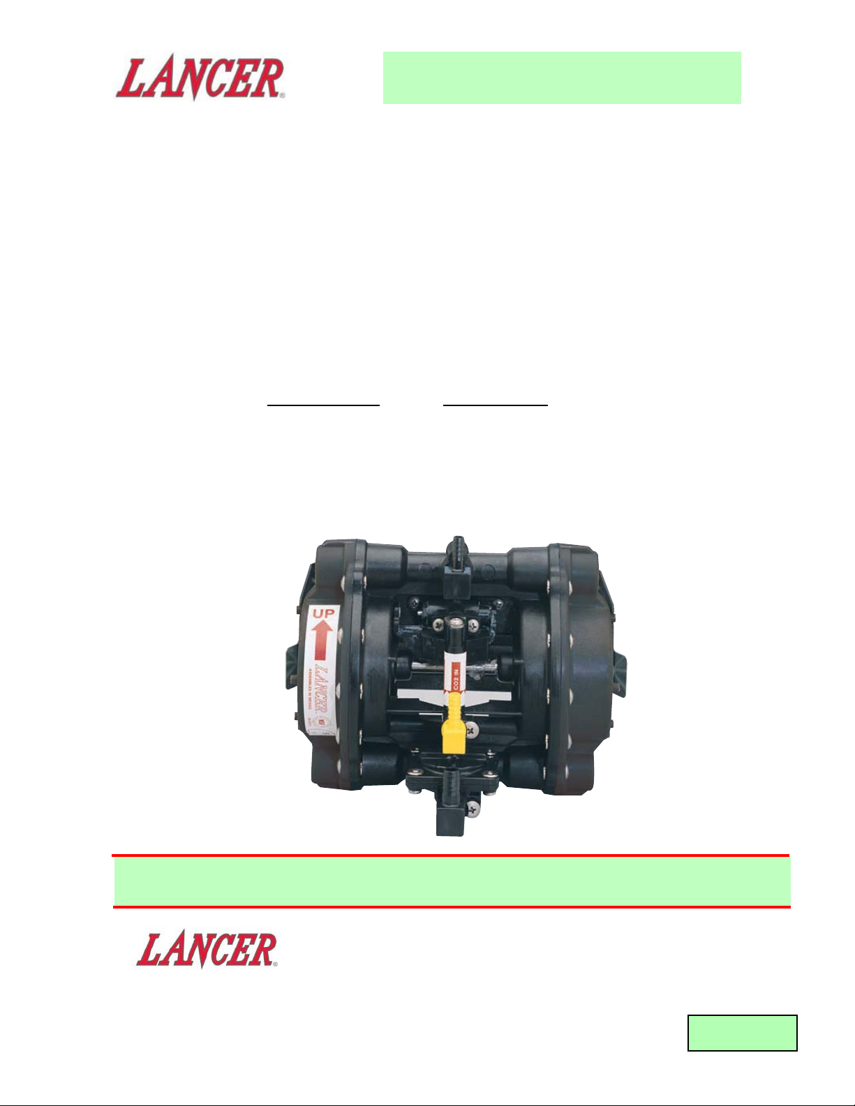
LANCER MAXI SYRUP PUMP
P
ART NUMBER DESCRIPTION
82-0109/01 (FAMILY) LANCER MAXI SYRUP PUMP
For use with Disposable Bag-in-Box (BIB) Package
This manual, reactivated and revised by Lancer in June 1997,
supersedes Installation Manual 28-0030, dated 08/07/90.
REV. 06/20/97
P.N. 28-0030/01
6655 LANCER BLVD. • SAN ANTONIO, TEXAS 78219 USA • (210) 310-7000
FAX SALES
• NORTH AMERICA – 210-310-7245 • INTERNATIONAL SALES – 210-310-7242 • CUSTOMER SERVICE – 210-310-7242 •
• LATIN AMERICA – 210-524-9567 / 210-310-7245 • EUROPE – 32-2-755-2399 • PACIFIC – 61-8-8268-1978 •
FAX ENGINEERING: • 210-310-7096
"Lancer" is the registered trademark of Lancer • Copyright — 1997 by Lancer, all rights reserved.
Please refer to the Lancer web site (www.lancercorp.com) for
information relating to Lancer Installation and Service Manuals,
Instruction Sheets, Technical Bulletins, Service Bulletins, etc.
Page 2

T
ABLE OF CONTENTS
1. GENERAL DESCRIPTION ..........................................................................................................................1
1.1 GENERAL INFORMATION ................................................................................................................1
1.2 SYRUP INLET FITTINGS ..................................................................................................................1
1.3 GAS INLET FITTING..........................................................................................................................1
2 PRINCIPLES OF OPERATION ...................................................................................................................1
2. INSTALLATION ...........................................................................................................................................2
2.1 RECEIVING AND INSPECTION ........................................................................................................2
2.2 LOCATION OF PUMP ........................................................................................................................2
2.3 CONNECTING LINES TO UNIT ........................................................................................................2
2.4 PREPARING UNIT FOR OPERATION ..............................................................................................3
2.5 SOLD-OUT DEVICE (MAY BE OPTIONAL ON SOME MODELS)....................................................3
3. SERVICE AND MAINTENANCE .................................................................................................................3
3.1 LUBRICATION....................................................................................................................................3
3.2 ADJUSTMENTS.................................................................................................................................4
3.3 PRIMING THE PUMP AT THE CORRECT PRESSURE ...................................................................4
3.4 CLEANING AND SANITIZING ...........................................................................................................4
3.5 REPLENISHING SYRUP SUPPLY ....................................................................................................5
3.6 WINTERIZING PUMP ........................................................................................................................6
4. TROUBLESHOOTING.................................................................................................................................6
4.1 PUMP WILL NOT CYCLE ..................................................................................................................6
4.2 PUMP WILL NOT STOP (WHEN DISPENSING VALVE IS CLOSED)..............................................6
4.3 PUMP WILL NOT PRIME...................................................................................................................7
4.1 PUMP WILL NOT DEVELOP PRESSURE ........................................................................................7
5. ILLUSTRATIONS AND PARTS LISTINGS .................................................................................................8
5.1 SYRUP PUMP ASSEMBLY (PN 82-0109/01) ....................................................................................8
5.2 REVERSING VALVE ASSEMBLY (PN 17-0406/01) ..........................................................................9
5.3 SOLD OUT VALVE (PN 17-0428) ....................................................................................................10
5.4 BRACKETS ......................................................................................................................................11
5.5 SYRUP INLET AND OUTLET FITTINGS.........................................................................................11
5.6 INLET GAS FITTINGS .....................................................................................................................11
i
Page 3
1. GENERAL DESCRIPTION
1.1 GENERAL INFORMATION
A. The Lancer Syrup Pump is a pneumatically operated, double acting, diaphragm pump. It is
designed to pump up to 1.5 ounces (45 ml) of syrup per second at up to 75 PSI (5.28 kg/cm2)
line pressure. Either CO2 gas or compressed air can be used to drive the pump. One pump is
required for each product dispensed.
NOTE
If compressed air is used, the compressed air must be dry and oil free.
B. Dimensions of the pump are 7.3 inches (18.6 cm) width x 4.5 inches (11.5 cm) depth x
6.0 inches (15.24 cm) height.
1.2 SYRUP INLET FITTINGS
A. Syrup inlet fittings are 3/8 inch (0.95 cm) barbed hose connector. Syrup outlet fittings are either
1/4 inch (0.635 cm) or 3/8 inch (0.95 cm) barbed connectors, depending on the tubing used.
1.3 GAS INLET FITTING
A. Gas inlet fitting is a 1/4 inch (0.635 cm) barbed hose connector.
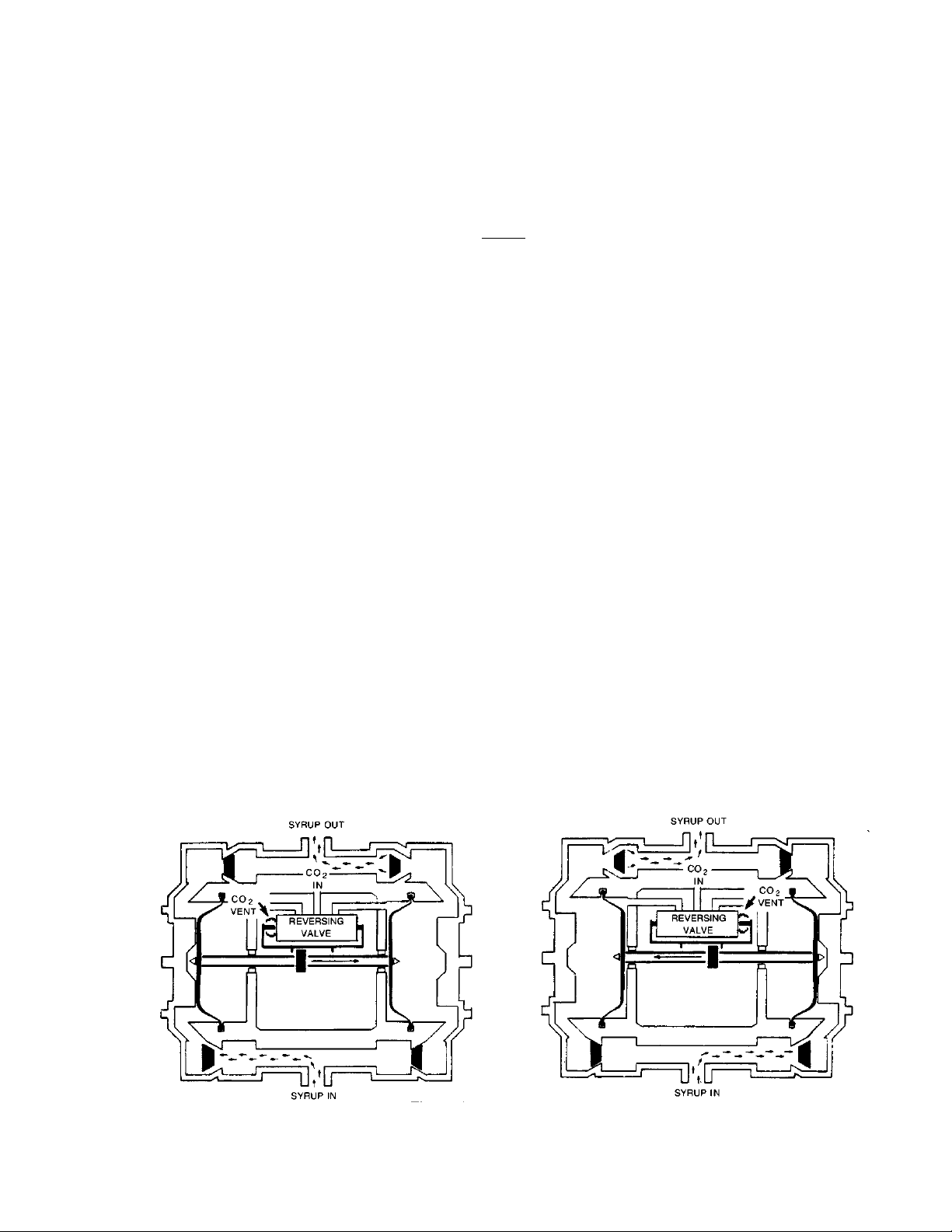
2. PRINCIPLES OF OPERATION
2.1 The following describes the Lancer syrup pump theory of operation:
A. When the system demands syrup for dispensing, gas pressure enters the reversing Valve and
is directed to the Gas Chamber on the right, while the Gas Chamber on the left is allowed to
exhaust gas. This causes the Diaphragm Assembly to move to the right (see Figure 1).
B. As the Diaphragm Assembly moves to the right, syrup is forced out of right side Chamber
through Check Valve and Syrup Outlet while syrup is sucked into the left side Chamber through
the Inlet Check Valve.
C. When the Diaphragm Assembly reaches the end of its stroke, the reversing Valve switches and
directs gas pressure to the left Gas Chamber while the right Gas chamber is allowed to exhaust
gas. This causes the Diaphragm Assembly to move to the left (see Figure 2).
D. As the Diaphragm Assembly moves to the left, syrup is forced out of the left side Chamber
through Check Valve and Pump Outlet while syrup is sucked into right side Chamber through
Inlet Check Valve. The syrup pump cycle will be repeated as many times as necessary to fulfill
syrup needs of Dispenser [approximately five (5) ounces (147.9 ml) of syrup are pumped per
cycle].
E. The Syrup Pump will pull syrup from a non-pressurized package. The Pump will normally
self-prime up to ten (10) feet (3.0 m).
1
Figure 1
Figure 2
Page 4
2. INSTALLATION
2.1 RECEIVING AND INSPECTION
A. Each Pump is tested and thoroughly inspected before shipment. At the time of shipment, the
carrier accepts the Pump and any claim for damages must be made with the carrier. Upon
receiving Dispensers from the delivering carrier, carefully inspect carton for visible
indication(s) of damage. If damage exists, have carrier note same on bill of lading and file a
claim with the carrier.
B. After Pump has been unpacked, remove shipping tape and other packing material. Check for
obvious damage and follow installation instructions. If shipping damage is evident, notify
delivering carrier and file claim against the same.
2.2 LOCATION OF PUMP
W
ARNING
CARBON DIOXIDE (CO2) IS A HEAVIER THAN AIR, COLORLESS, NONCOMBUSTIBLE GAS
WITH A FAINTLY PUNGENT ODOR. SINCE HIGH PERCENTAGES OF CO2 MAY DISPLACE
OXYGEN IN THE BLOOD, PROLONGED EXPOSURE TO CO2 MAY BE HARMFUL.
A. Syrup Pumps that are operated by CO
2 gas should be installed in well ventilated areas.
B. If a Syrup Pump is installed in a basement, it should be operated on compressed air. CO2 gas
may be used for a basement installation, provided the area has a positive ventilation system
(exhaust fans) capable of changing the room air every 20 minutes (minimum) or a vented Pump
is used.
C. It is best to locate the Syrup Pump in a place near the syrup supply to keep the line from the
package to the Pump Inlet as short as possible. A maximum recommended Syrup Inlet Line is
12 feet (3.66 m) of 0.375 inch (0.95 cm), or larger, ID tubing must be used.
D. The Syrup Pump must be installed above the syrup package, but no more than 10 feet (3.0 m)
higher than the syrup package.
E. The Syrup Pump should be mounted on a wall or other support using the Bracket provided on
the Pump Body. Mounting should be horizontal with the Syrup Outlet Line as the top as shown
in Figure 3. The Pump is identified showing IN and OUT ports and direction of mounting.
F. Used enclosed Screws provided for mounting the Syrup Pump Bracket.
2.3 CONNECTING LINES TO UNIT
A Syrup Inlet Line, a Syrup Outlet Line and a Gas line must be connected to the Syrup Pump for
operation (see Figure 3).
B. Attach 0.375 inch (0.95 cm) ID by 0.630 inch (1.6 cm) OD, approved, vinyl beverage tubing line
to the Inlet Fitting on the Pump and attach a Bag-in-Box (BIB) Quick Disconnect Coupling to the
other end of the tubing.
2
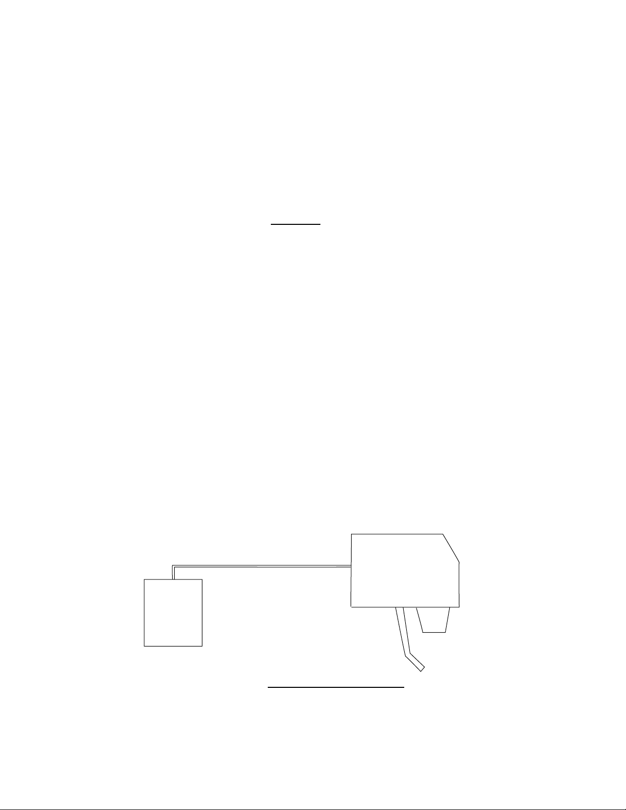
Diagram of Pressure Drop-BIB Syrup Container to Valve
Figure 3
50 FEET (15 M) 0.265 INCH I.D. BEVERAGE TUBING
BIB
SYRUP
CONTAINER
FIRST 10 FEET (3 M) OF TUBING 35 PSI (2.5 KG/CM ) PRESSURE
FIRST 40 FEET (12 M) OF TUBING 12 PSI (0.85 KG/CM ) PRESSURE
47 PSI (3.3 KG/CM MINIMUM REQUIRED CO
OR AIR PRESSURE
2
2
2
VALVE
2
Page 5

C. Attach 0.265 inch (0.635 cm) ID braided beverage tubing from the Outlet Fitting on the Pump to
the Dispenser. Where a long run to the Dispenser is encountered, use 0.375 inch (0.95 cm) ID
braided beverage tubing.
D. Attach 0.265 inch (0.635 cm) ID braided beverage tubing from the Gas Regulator to the Pump
Inlet Gas Fitting.
E. If Pump is operated by compressed air, the supply line from the air compressor should include
a five (5) micron air filter. If the compressed air contains a substantial amount of water, a drier
should be used to remove the water. Excess water in the air supply will wash the lubricant out
of the Reversing Air Valve and cause excessive wear of the O-Rings, and thereby shorten the
life of the Pump.
2.4 PREPARING UNIT FOR OPERATION
CAUTION
DO NOT OPERATE THE PUMP WITHOUT SYRUP SINCE THIS COULD DAMAGE THE
DIAPHRAGM OVER A PERIOD OF TIME. THE GAS LINE TO THE PUMP MUST BE
CONTROLLED BY A LOW PRESSURE CO2 REGULATOR CAPABLE OF BEING SET WITH UP
TO 75 PSI (5.28 KG/CM2) OUTLET PRESSURE.
A. After all lines and a full BIB Package have been connected to the Pump, turn on the Gas
Pressure and adjust the Regulator Pressure between 35 and 75 PSI (2.5 kg/cm
2
and
5.28 kg/cm
2
).
NOTE
Pumps for sugar free products can be operated at the same pressure as other products since
there is no contact between the syrup and gas.
B. Bleed off air in the system by opening Dispensing Valve until flow is steady and full. After air is
removed, no bubbles should be seen in Inlet and Outlet Lines to the Pump. If bubbles appear,
check for leak(s) in the Inlet Line.
C. The minimum pressure needed for an installation is 35 pounds (2.5 kg/cm2) for packages
within I0 feet (3 m) of the Dispenser. For packages located more than 10 feet (3 m) from the
Dispenser, add 3 pounds (0.21 kg/cm
2
) for each additional 10 feet (3 m).
CAUTION
GAS PRESSURE TO PUMP MUST NOT EXCEED 75 PSI (5.28 KG/CM2).
NOTE
Examples below are for 0.265 inch ID beverage tubing. The pressure drop for 0.375 inch ID
beverage tubing is approximately one-third (1/3) of that for 0.265 inch ID beverage tubing.
D. After removing air and setting Regulator for correct pressure, set the proper syrup/water ratio or
brix for the product.
E. Pump will now operate automatically when drinks are dispensed. If pump continues to cycle
after dispensing is stopped, bleed system to remove air and check for syrup and/or air leaks.
2.5 SOLD-OUT DEVICE (MAY BE OPTIONAL ON SOME MODELS)
A. An optional Sold-Out Device can be used to automatically shut off the Syrup Pump when the
Package(s) is empty. This stops the operation of the Pump and the exhaust of gas until a new
syrup package is connected to the Pump.
B. The Lancer Sold-Out device measures syrup vacuum in the Pump Inlet Line. When the Syrup
Package is empty, the Pump increases vacuum causing the device to shut off the gas pressure
to stop the Pump. The Lancer Sold-Out automatically resets, after new Syrup Packages are
connected.
3. SERVICE AND MAINTENANCE
3.1 LUBRICATION
PUMPS ARE FACTORY LUBRICATED. FIELD LUBRICATION IS NOT
NECESSARY.
3
Page 6

3.2 ADJUSTMENTS
A. There are no adjustments to be made on the Syrup Pump.
B. Once the gas pressure has been set for dispensing, it should be rechecked periodically to assure
continued operation.
3.3 PRIMING THE PUMP AT THE CORRECT PRESSURE
A. For the Syrup Pump to operate correctly, it is necessary to remove all air from the system. After
all lines to the Syrup Pump and Syrup Packages are connected and CO
2 (or air pressure) is set,
the system should be primed as follows:
1. Disconnect Wire to Soda Solenoid or close Shut Off Valve on soda side so that only syrup
will be dispensed when Dispensing Valve is operated.
2. Operate Valve for five (5) seconds and then release for five (5) seconds. Continue drawing
syrup until flow is steady and full.
3. After priming, look for air pockets in Syrup Inlet or Outlet Lines. Repeat priming to remove
any air pockets found.
4. After priming, replace the Wire to Soda Solenoid or open Soda Shut Off Valve on Dispensing
Valve.
5. Repeat above procedure for all Syrup Pumps.
3.4 CLEANING AND SANITIZING
A. General Information
(1) Lancer equipment (new or reconditioned) is shipped from the factory cleaned and sanitized
in accordance with NSF guidelines. The operator of the equipment must provide continuous
maintenance as required by this manual and/or state and local health department guidelines
to ensure proper operation and sanitation requirements are maintained.
NOTE
The cleaning and sanitizing procedures provided herein pertain to the Lancer equipment
identified by this manual. If other equipment is being cleaned, follow the guidelines
established for that equipment.
(2) Cleaning and sanitizing should be accomplished only by trained personnel. Sanitary gloves
are to be used during cleaning and sanitizing operations. Applicable safety precautions
must be observed. Instruction warnings on the product being used must be followed.
CAUTION
WATER LINES ARE NOT TO BE DISCONNECTED DURING THE CLEANING AND
SANITIZING OF SYRUP LINES TO AVOID CONTAMINATION.
(3) Recommended Preparation of Cleaning Solutions.
(a) Cleaning solutions (for example, Ivory Liquid, Calgon, etc.) mixed with clean, potable
water at a temperature of 90 to 110 degrees Fahrenheit (32oC to 43oC) should be used
to clean equipment. The mixture ratio, using Ivory Liquid, is one (1) ounce (30 ml) of
cleanser to two (2) gallons (7.5 L) of water. Approximately four (4) gallons (15 L) of
cleaning mixture should be prepared.
NOTE
Extended lengths of product lines may require that an additional volume of solution be
prepared.
(b) Any equivalent cleanser may be used as long as it provides a caustic based,
non-perfumed, easily rinsed mixture containing at least two (2) percent sodium
hydroxide (NaOH).
(4) Recommended Preparation of Sanitizing Solutions.
(a) Sanitizing solutions should be prepared in accordance with the manufacturer’s written
recommendations and safety guidelines. Mix sanitizing solution in clean, potable water
at a temperature of 90 to 110 degrees Fahrenheit (32
o
C to 43oC) so that the solution
4
Page 7

provides 50 to 100 parts per million (PPM) available chlorine. Approximately four (4)
gallons (15 L) of sanitizing solution should be prepared.
NOTE
Extended lengths of product lines may require that an additional volume of solution be
prepared.
(b) Any equivalent sanitizing solution may be used as long as it is prepared in accordance
with the manufacturer’s written recommendations and safety guidelines, and provides
50 to 100 parts per million (PPM) available chlorine.
B. Cleaning of the Syrup Pump is required every six (6) months under normal use conditions.
C. Five step sanitizing procedure.
1 Disconnect each Syrup Quick Disconnect Coupling from Syrup Packages and connect
Coupling to a Bag Valve removed from an empty BIB package.
2. Fill clean empty container with potable (drinking water) flush water, then place all Syrup Inlet
Lines in flush water.
3. Depress and hold each Dispensing Valve until no more syrup flows from Dispensing Spout,
then release and wait five (5) seconds. Repeat procedure until syrup is purged from system
and clear flush water flows from each Dispensing Spout.
4. Remove flush water container after all syrup systems are flushed.
5. Following manufacturer's instructions, prepare detergent solution in clean container.
6. Place all Syrup Inlet Lines in detergent solution container.
7. Repeat Step 3 above, purging flush water from each syrup system until detergent
solution flows from all Dispensing Spouts.
8 Allow detergent solution to remain in syrup system for a contact time of at least ten (10)
minutes. Replace detergent solution container with flush water container.
10. Repeat step 3 above, purging of detergent solution from each syrup system and until flush
water flows from each Dispensing Spout.
11. Following manufacturer's instructions, prepare sanitizing (chlorine) solution in clean
container to a concentration of 50 ppm chlorine.
12. Place all Pump Inlet Lines in sanitizing solution container.
13. Repeat Step 3 above, purging flush water from each syrup system until sanitizing solution
flows from all Dispensing Spouts.
14. Allow sanitizing solution to remain in syrup systems for a contact time of 30 minutes.
15. Remove Bag Valves from Quick Disconnect Couplings and reconnect Syrup Packages to
Syrup Inlet Lines.
16. Purge the sanitizing solution from each syrup system using syrup. Continue to flush system
until off-taste disappears.
NOTE:
NSF does NOT allow a water flush after sanitizing.
17. Test Dispenser in normal manner for proper operation. Test dispensed product to ensure
there is no off-taste. If off-taste is found, additional flushing of syrup system may be
required.
C. Yearly Maintenance.
1 Follow Lubrication instruction in Section 3.1.
2. If Pump has a Sold-Out Device, it should be tested for proper operation. Disconnect Syrup
Package(s) from Pump to see that Sold-Out Device Shuts off Pump. Reconnect Syrup
Package(s). The Lancer Sold-Out Device resets automatically. The Sold-Out Device
requires no lubrication.
3. If Pump is operated by compressed air, the gas supply line should include an air filter with a
five (5) micron filter element. The element should be replaced no less than yearly.
3.5 REPLENISHING SYRUP SUPPLY
A. Remove empty Syrup Package from system by turning Collar on Quick Disconnect Coupling
counterclockwise.
5
Page 8

B. On a new Package, push in on tab located above perforated opening flap.
C. After breaking seal on flap, pull the flap up.
D. Reach in the box and pull the Bag Valve out. Remove the Dust Cap (see Figure 4).
E. Connect the Quick Disconnect Coupling by turning the Collar clockwise until stopped by the Bag
Valve.
F. The Lancer Sold-Out Device will reset automatically.
G. If air has entered the Syrup System, prime the Syrup Pump following the instructions in
Section 3.3.
3.6 WINTERIZING PUMP
A. On a Pump removed from accounts, ensure that all sanitizing steps (see Section 3.4.B) have
been completed.
B. Remove water by operating Pump with CO
2 or air.
C. Turn Pump on side with fittings down. Let drain and store in original shipping carton.
Figure 4
4 TROUBLESHOOTING
TROUBLE
CAUSE REMEDY
4.1 Pump will not cycle. A. Sold-Out Device has not A. Check for full syrup package
been reset. and pull reset Lever.
NOTE: Lancer Sold-Out Device
should reset automatically.
B. Out of CO2 Gas or Gas B. Replace CO2 Cylinder or open
Valve closed. Cylinder Valve.
C. Air pressure off. C. Plug in Compressor Power Cord.
Check Circuit Breaker fuse.
D. Valve at Dispenser does D. Open Shut Off Valves, replace
not open. defective Switches, Solenoids,
Wiring, etc.
E. Defective reversing Valve. E. Replace reversing Valve.
F. Syrup Line frozen in F. Thaw Dispenser.
Dispenser.
G. Defective Sold-Out Device. G. Replace Sold-Out Device.
4.2 Pump will not stop A. Air in system. A. Bleed air from system.
(when Dispensing B. Syrup leak on Pump B. Stop leak.
Valve is closed). Discharge Line.
C. Out of syrup and no Sold-Out C. Replace empty packages with
Device on system. new full packages.
D. Defective Pump Check Valves. D. Replace defective Pump Check
Valve.
6
Page 9

4.3 Pump will not prime. A. Defective Pump Inlet Check A. Replace Inlet Check Valves.
Valve.
B. Air leak on Inlet Line (CO2). B. Find and stop leak.
C. Quick Disconnect Coupling C. Tighten Collar on Coupling until
not open. it is stopped by Bag Valve.
D. Leak in Syrup Package (see D. Replace with new Package.
note).
E. Kink in Syrup Inlet Line. E. Remove Line kink.
NOTE: It may be necessary to turn the package on its side to determine if
bag leaks. If Pump has a Sold- Out Switch, squeeze Inlet Line closed
and Pump should stop.
4.5 Pump will not A. Pressure in gas or Air Line A. Increase Gas or Air pressure.
develop pressure. set too low.
B. Defective Pump Outlet Check B. Replace Outlet Check Valves.
Valve O-Ring.
C. Too many Dispensing Faucets C. Install more Pumps.
being served by Pump (see
note).
NOTE: No more than six (6) Standard Flow (1-1/2 oz/sec) Valves or
three (3) Fast Flow (3 oz/sec) Valves should be connected to each
pump.
TROUBLE CAUSE
REMEDY
7
Page 10

8
5. ILLUSTRATIONS AND PARTS LISTS
5.1 SYRUP PUMP ASSEMBLY (PN 82-0109/01)
ITEM PART
NO. DESCRIPTION
R 1 05-0125/02 End Cap (Black)
2 82-0110 Pump Body Assy
2a 82-0277 Pump Body Assy, Vented
3 10-0063 Shaft
4 10-0045 Washer
5 03-0055 Retaining Ring
6 02-0092 O-Ring
7 05-0131 Bushing
8 05-0128 Retainer
9 04-0304 Washer
R 10 02-0128/01 Diaphragm
R 11 23-0155/01 Piston Assy
12 05-0123 Check Valve Body
13 02-0068 O-Ring
14 02-0097 Check Valve
R 15 04-0624 Screw
R 16 17-0406/01 Reversing Valve Assy
16a 17-0416 Reversing Valve Assy, Vented
17 04-0299 Screw
18 02-0085 O-Ring
R 19 06-0474/01 Label
NOTE: R in margin indicates revision.
Page 11

5.2 REVERSING VALVE ASSEMBLY (PN 17-0406/01)
9
ITEM PART NO DESCRIPTION
R 1 05-0117/01 Valve Body
- 05-0218 Valve Body, Vented
2 05-0116 Cover
3 82-0285 Actuator Assy, Plastic
4 82-0111 Spool Assy
5 02-0091 O-Ring (for Spool Assy)
6 10-0055 Sleeve
7 10-0056 Cage
8 02-0003 O-Ring
9 04-0158 Screw
R 10 05-0115/01 Threaded End Cap
- 05-0216 Threaded End Cap, Vented
R 11 05-0129/01 Spring Guide
R 12 05-0130/01 Spring Retainer
13 03-0052 Spring
NOTE: R in margin indicates revision.
Page 12

5.3 SOLD OUT VALVE (PN 17-0428)
10
ITEM PART NO. DESCRIPTION
- 17-0428 Sold Out Valve, Complete
1 05-0227 Body, Upper Assy
2 05-0225 Body, Lower
3 05-0075 Piston
4 02-0117 Diaphragm
5 01-1059 Plug Assy
- 02-0005 O-Ring for Plug Assy
6 04-0266 Screw
7 03-0086 Retainer Ring
8 03-0005 Retainer
9 82-0204 Shaft Assy
- 02-0125 O-Ring for Shaft Assy
10 02-0089 O-Ring
R 11 03-0080/01 Spring
12 04-0155 Screw
13 02-0005 O-Ring
14 06-0173 Label
NOTE: R in margin indicates revision.
Page 13

ITEM PART NO. DESCRIPTION
1 51-0372 Wall Bracket
2 04-0289 Screw
3 23-0142 Pump Bracket Assy
4 04-0251 Screw
5.4 BRACKETS
11
2
1
3
4
5.5 SYRUP INLET AND OUTLET FITTINGS
ITEM
PART NO. DESCRIPTION
1 03-0056 Retainer
2 04-0155 Screw
3 02-0089 O-Ring
4 01-0774 Adaptor, Straight, 1/4 Inch Barb, SS
- 01-0804 Adaptor, Straight, 3/8 Inch Barb, SS
- 01-1095 Elbow, 1/4 Inch Barb, SS
R - 01-0844 Elbow, 3/8 Inch Barb, SS
5 04-0275 Screw
6 01-1040 Adaptor, Straight, 1/4 Inch Barb,
Plastic
- 01-1039 Adaptor, Straight, 3/8 Inch Barb,
Plastic
- 01-1074 Elbow, 1/4 Inch Barb, Plastic
- 01-1073 Elbow, 3/8 Inch Barb, Plastic
NOTE: R in margin indicates revision.
1
2
3
4
5
3
6
5.6 INLET GAS FITTINGS
ITEM
PART NO. DESCRIPTION
1 03-0005 Retainer
2 04-0155 Screw
3 02-0005 O-Ring
4 01-0337 Adaptor, Straight, 1/4 Inch Barb, SS
R - 01-0416 Elbow, 1/4 Inch Barb, SS
5 04-0275 Screw
6 01-1072 Elbow, 1/4 Inch Barb, Plastic
- 01-1194 Elbow, 1/4 Inch Barb, Plastic, with
Check Valves
NOTE: R in margin indicates revision.
1
2
3
4
5
3
6
Page 14

12
NOTES
Page 15

13
(Continued from previous page)
EcuaLancer S.A. - Ecuador
Lancer Sales Company
Contact: Luciano Lopez
Sector Las Acacias
Luis De Beethoven #958
Y Capitan Rafael Ramos
Quito, Ecuador
Phone: 593-22-401-598, 400-937, 406-418
FAX: 593-22-400-535
e-mail: Llopez@ecnet.ec
Lancer Authorized Distributors
Eximport & Barter Co. - Caribbean
2101 S.W. 56th Terrace
Hollywood, FL 33023 USA
Phone: (954) 967-9999
FAX: (954) 967-9900
e-mail: edbrandao@aol.com
PromoVen, S.A. - Argentina
Contact: Rafael Mendoza
Juncal 858 - Piso 3 Depto. “L”
(1062) Buenos Aires
Argentina
Phone: (54.11)4394.7654
FAX: (54.11)4394.1193
e-mail: promoven@customw.com.ar
Bras Sulamericana LTDA. - Brasil
Contact: Fabio Queiroz
Rua. Dr. Ladislau Retti, 1400
Parque Alexandre
Cotia Sao Paulo - Brasil
CEP: 06714-150
Phone: 55-11-4612-1122
FAX: 55-11-4612-2219
e-mail: fabio.queiroz@bras.com.br
Lancer Chile Ltda. - Chile
Contact: Heriberto Concha
Vicuna Mackenna 3019, San Joaquin
Santiago, Chile
Phone: 56-2-552-1657
FAX: 56-2-552-1961
e-mail: hconcha@lancer-intl.com
Lancer Pacific
International Sales
6655 Lancer Blvd.
San Antonio, TX 78219
Phone: (210) 310-7000
FAX: (210) 310-7242
1-800-729-1500
e-mail: asia@lancercorp.com
Australia
Lancer Pacific Pty Ltd
5 Toogood Avenue
Beverley SA 5009
Australia
Phone: 61-8-8268-1388
FAX: 61-8-8268-1978
e-mail: ian-lunniss@lancer-pacific.com.au
steve-sotiriou@lancer-pacific.com.au
Lancer Pacific Pty Ltd
7 Slough Avenue
Silverwater, NSW, 2128
Sydney, Australia
Phone: 61-2-9648-6840
FAX: 61-2-9648-6850
e-mail: richard-abraham@lancer-
pacific.com.au
fiore-alvaro@lancer-pacific.com.au
(for Beer)
rob-burdock@lancer-pacific.com.au
(Senior Director - Asia)
R.B.P. Industrial Sales Inc - Philippines
Unit 20, Facilities Centre Bldg.
548 Shaw Blvd
Mandaluyong City, Philippines
Phone: 632-531-1215/1221/1289
FAX: 632-531-1271
e-mail: rbpsales@info.com.ph
Freser (S) Pte Ltd - Singapore
Blk 998 Toa Payoh North
#04-12/14
Singapore 318993
Phone: 65-6352-0943
FAX: 65-6352-8594
e-mail: fresersin@pacific.net.sg
Freser International Corporation - Taiwan
No. 76, Gui-Sui Street
Taipei 103, Taiwan R.O.C.
Phone: 886-2-2553-1555
FAX: 886-2-2553-2742
e-mail: allen@intl.freser.com.tw
Freser (Thailand) Co Ltd - Thailand
3/15 Moo 3, Soi Ruammitr
Tivanont Road, Banmai
Pakkred, Nonthaburi, 11120
Thailand
Phone: 662-961-9543
FAX: 662-961-9550
e-mail: prachat@asianet.co.th
Lancer - Indian Sub-Continent
India
Shabbir Shafiqui - Area Manager
India and Sub-Continent
B-7, Pannalal Silk Mill Compounds
78, LBS Marg, Bhandup (W)
Mumbai 400-078, India
Phone: 91-22-2561-6665
Cel No.: 91-98-2029-5252
FAX: 91-22-5637-4018
e-mail: shafiquis@vsnl.com
Lancer Authorized Distributors
Western Refrigeration Ltd - India
B-7, Pannalal Silk Mill Compounds
78 L.B.S. Marg, Bhandup (W)
Mumbai 400-078, India
Phone: 91-22-2561-6665
FAX: 91-22-2562-2257
e-mail: western@bom5.vsnl.net.in
Bengal Marketing Company - Bangladesh
Skylark Point (6th Floor)
Room #G-2
24/A Bijoy Nagar,
Dhaka-1000, Bangladesh
Phone: 880-2-934-2987
FAX: 880-2-935-0127
e-mail: bmc@dhaka.agni.com
Dynamic Equipment - Pakistan
Dynamic Equipment and Controls (Pvt.) Ltd.
F-1/23, Canal Cottages, Block-D.
New Muslim Town.
Lahore. Pakistan.
Phone: 0092-42-583-6737
0092-42-583-6787
FAX: 0092-42-586-7924
e-mail: info@dynamic-eqpt.com.pk
Lancer Pacific Pty Ltd
55 Keele Street
Collingwood
Melbourne Victoria 3066
Australia
Phone: 03 8415 1920
FAX: 03 8415 1929
e-mail: glenn-blakiston@lancer-pacific.com.au
Lancer Pacific Pty Ltd
Unit 31, 284 Musgrave Drive
Coopers Plains 4108
Queensland
Australia
Phone: 61-7-3274-5700
FAX: 61-7-3875-1805
e-mail: brett-thomson@lancer-pacific.com.au
New Zealand
Lancer Pacific Ltd
9 O’Rorke Street
Onehunga, Auckland
New Zealand
Phone: 64-9-634-3612
FAX: 64-9-634-1472
e-mail: phil-mason@lancer-pacific.com.au
Hong Kong
Patrick Co - Area Manager - Asia
Phone: 852-29670900
FAX: 852-30105882
e-mail: patrickco@lancer-asia.com
Lancer Authorized Distributors
Shanghai Freser International Co Ltd. China
1856, Hu Tai Road
Shanghai, 200436, China
Phone: 86-21-5650-3555
FAX: 86-21-5650-2666
e-mail: daniel@freser.com.cn
Freser (HK) Company Ltd - Hong Kong
Flat A, 24/F., Houston Industrial Bldg.
32-40 Wang Lung Street
Tsuen Wan, N. T., Hong Kong
Phone: 852-2408-2595
FAX: 852-2408-2605
e-mail: freserhk@netvigator.com
P.T. Ciptapratama Sentosamakmur Indonesia
JI. Anggrek Nelly Murni, Blok A - 39, Slipi
Jakarta 11480, Indonesia
Phone: 62-21-532-3737
FAX: 62-21-532-3666
e-mail: ciptasm@indosat.net.id
Hayakawa Sanki - Japan
Hayakawa Sanki, Inc.
1-13-13, Kayaba-cho
Nihonbashi, Chuo-ku
Tokyo, 103-0025
Japan
Phone: 03-5651-1481
FAX: 03-5651-1445
e-mail: SANKI10217@aol.com
Tahoe Corporation - Korea
Tahoe Corporation
2FL, 835-66 Yocksam-dong
Kangnam-Ku
Seoul, Korea
Phone: 82-2-557-5612, -5614
FAX: 82-2-557-5615
e-mail: tahoepark@netsgo.com
Freser (MALAYSIA) SDN. BHD. - Malaysia
No. 31, Jalan TPP 5/13, Taman
Perindustrian Puchong, Seksyen 5,
47100 Puchong, Selangor, Malaysia
Phone: 60-3-8061-6666
FAX: 60-3-8062-1007
e-mail: freser@tm.net.my
Directory of USA - Canada Offices,
International Offices, and Authorized Distributors
(Continued)
Page 16

14
Lancer USA
Manufacturing Locations
Foster Road Facilities
6655 Lancer Blvd
San Antonio, TX 78219
Phone: (210) 310-7000
MFG FAX: (210) 310-7088
ENG FAX: (210) 310-7096
ACCT FAX: (210) 310-7091
PURCH FAX: (210) 310-7094
Lancer FBD
5620 Business Park
San Antonio, TX 78218
Phone: (210) 666-0544
FAX: (210) 666-2044
Lancer Ice Link
6655 Lancer Blvd
San Antonio, TX 78219
Phone: (210) 310-7174
FAX: (210) 310-7245
Remanufacturing
6655 Lancer Blvd
San Antonio, TX 78219
Phone: (210) 310-7356
FAX: (210) 310-7261
1-800-729-1550
Lancer North America
USA - Canada Sales
6655 Lancer Blvd.
San Antonio, TX 78219
Phone: (210) 310-7000
SALES FAX: (210) 310-7245
CUSTOMER SERVICE FAX: (210) 310-7250
1-800-729-1500
Georgia Office
1125 Northmeadow Parkway, Suite 116
Roswell, GA 30076
Phone: (770) 343-8828
FAX: (770) 475-8646
1-800-729-1750
Lancer Authorized Distributors
Advanced Beverage Solutions (ABS)
1425 South Wright Blvd.
Schaumburg, IL 60193
Phone: (847) 524-1707
(877) 814-2271
FAX: (847) 524-1710
www.absone.com
Bevco
6900 Camille Avenue
Oklahoma City, OK 73149
Phone: (405) 672-7770
FAX: (405) 672-7443
e-mail: info@bevcoinc.com
Joe Kirwan Company
119 White Oak Lane
Old Bridge, NJ 08857
Phone: (732) 679-1900
FAX: (732) 679-9236
e-mail: sales@jkirwan.com
L & M Beverage Equipment Co. Inc.
12510 Santa Fe Trail Drive
Lenexa, KS 66215
Phone: (913) 888-8988
FAX: (913) 888-9137
e-mail: L7mco@aol.com
(Update #43 - as of March 05, 2003)
Lancer Russia
Lancer Sales Company
Vyatskaya Street 27
Building 15, 4th Floor
125015 Moscow, Russia
Phone: 7-095-745-7108
FAX: 7-095-745-7109
Mobile Phone: 7-095-991-7778
7-095-139-0335
e-mail: lancer@online.ru
vdemkin@ktv.ru
Lancer Middle East / Africa
Elsayed Moniem - Technical Manager
Lancer Middle East/Africa
7 Mubarak Street
East Ain Shams 11311
Cairo, Egypt
Phone/FAX: 2-02-49-35-395
Mobile Phone (GSM): 2-010-500-4007
e-mail: elsayed_lancer@msn.com
Lancer Authorized Distributor
DispenseTech - South Africa
P.O. Box 17495
Sunward Park, 1470
South Africa
Phone: 27-11-397-7455
FAX: 27-11-397-7648
e-mail: david@dispensetech.co.za
Lancer Latin America
Latin America Sales
6655 Lancer Blvd.
San Antonio, TX 78219
Phone: (210) 310-7000
FAX: (210) 310-7245
1-800-729-1500
e-mail: latinamerica@lancercorp.com
Lancer de México, S.A. de C.V.
Contact: Gerardo Canales
Calle Lerdo De Tejada #544 PTE.
Col. Las Villas
San Nicolas De Los Garza, N.L.
Monterrey, N. L., México C.P. 66422
Phone: (52)-81-83-52-85-32
Phone: (52)-81-83-52-85-34
Phone: (52)-81-83-52-53-60
FAX: (52)-81-83-32-54-10
e-mail: direccion@lancer.com.mx
Lancer de México, S.A. de C.V.
Branch Office, Mexico City
Contact: Carlos Lopez
Lancer de Mexico S.A. de C.V.
Sucursal Mexico D.F.
Calle: Centeotl No. 112
Colonia: La Preciosa
Delegacion: Azcapotzalco
Mexico D.F. C.P. 02460
Phone: (52)-55-53-53-89-28
Phone: (52)-55-53-53-89-26
Phone: (52)-55-53-53-88-60
Phone: (52)-55-53-53-88-21
FAX: (52)-55-53-52-46-30
e-mail: lancer@prodigy.net.mx
Lancer de México, Branch Office, Cd.
Juarez
Contact: Yolanda Puga
Lancer de Mexico
Camino de la Lomas # 4380
Col. Partido Iglesias
Cd. Juarez, CHIH, C.P. 32617
México
Phone and FAX: 521-605-00-86
Phone: 521-605-00-87
e-mail: cdjuarez@lancer.com.mx
(Continued on reverse)
Ernest F. Mariani Company
614 West 600 South
Salt Lake City, UT 84104
Phone: (801) 359-3744
FAX: (801) 531-9615
e-mail: febell@efmco.com, or
clay@efmco.com
Mark Powers & Company, Inc.
P.O. Box 72
1821 Henry Street
Guntersville, AL 35976
Phone: (256) 582-6620
FAX: (256) 582-8533
e-mail: sales@markpowers-and-company.com
Maurer Supply, Inc.
843 Rainier Avenue South
Seattle, WA 98144
Phone: (206) 323-8640
FAX: (206) 323-9286
e-mail: maurersupply@qwest.net
Simgo Ltd.
5122 Timberlea Blvd.
Mississauga, Ontario L4W 2S5
Canada
Phone: 905-602-5800
FAX: 905-602-5804
e-mail: simgo@simgo.com
Simgo (B.C.) Ltd.
16-8125 - 130th Street
Surrey, B.C. V3W 7X4
Canada
Phone: 604-590-4022
FAX: 604-590-1601
Lancer Europe
Belgium - European Central Office
Lancer Europe, S.A.
Mechelsesteenweg 592
B-1930 Zaventem
Belgium
Phone: 32-2-755-2390
FAX: 32-2-755-2399
e-mail: lancer.europe@glo.be
England
17 Bembridge Gardens
Ruislip, Middlesex
HA4 7ER, England
Phone: 44-1895672667
FAX: 44-1895637537
e-mail: court4lancer@msn.com
Hungary
H-2100 Gödöllõ
Isaszegi út 67
Hungary
Phone: 36-28-417-179
FAX: 36-28416-881
e-mail: bodolai@compuserve.com
Lancer Authorized Distributors
Complete Beverage Services, Ltd.
Republic of Ireland and Northern Ireland
Gortrush Industrial Estate
Omagh County Tyrone
Northern Ireland
Office: 44-1662 250 008
FAX: 44-1662-252-991
Intercom - Spain
Intercom
Avda. Concha Espina 8
28036 Madrid Spain
Phone: 34-91-564 6900
FAX: 34-91-564 3065
e-mail: jmorales@bevserv.com
Directory of USA - Canada Offices,
International Offices, and Authorized Distributors
Corporate Office
6655 Lancer Blvd. • San Antonio, Texas 78219 • 210-310-7000 • 1-800-729-1500 • FAX 210-310-7250
 Loading...