

Page 1
INSTALLATION AND SERVICE MANUAL
LANCER SERIES 800
COUNTER ELECTRIC DISPENSER
100VAC/50-60HZ SERVICE
REV: 02/26/99
P.N. 28–0421
This Manual is an initial issue.
USA Patent Number: 5,499,744
Manufactured for
FAX ENGINEERING: • 210-310-7096
"Lancer" is the registered trademark of Lancer • Copyright — 1999 by Lancer, all rights reserved.
Please refer to the Lancer web site (www.lancercorp.com) for
information relating to Lancer Installation and Service Manuals,
Instruction Sheets, Technical Bulletins, Service Bulletins, etc.
6655 LANCER BLVD. • SAN ANTONIO, TEXAS 78219 USA • (210) 310-7000
FAX SALES
• NORTH AMERICA – 210-310-7245 • INTERNATIONAL SALES – 210-310-7242 • CUSTOMER SERVICE – 210-310-7242 •
• LATIN AMERICA – 210-310-7245 • EUROPE – 32-2-755-2399 • PACIFIC – 61-8-8268-1978 •
Page 2

INTENTIONALLY LEFT BLANK
Page 3

TABLE OF CONTENTS
TABLE OF CONTENTS ......................................................................................................................................i
SPECIFICATIONS.............................................................................................................................................iii
DISPENSER INSTALLATION HIGHLIGHTS....................................................................................................iii
1. INSTALLATION ...........................................................................................................................................1
1.1 RECEIVING .......................................................................................................................................1
1.2 UNPACKING ......................................................................................................................................1
1.3 UNPACKING INSTALLATION KITS ...................................................................................................1
1.4 SELECTING A COUNTER LOCATION .............................................................................................1
1.5 MOUNTING THE DISPENSER..........................................................................................................1
1.6 CONNECTING THE DRAIN...............................................................................................................1
1.7 FILLING UNIT WITH WATER ............................................................................................................2
1.8 CONNECTING TO ELECTRICAL POWER .......................................................................................2
1.9 CONNECTING TO WATER SUPPLY.................................................................................................2
1.10 CONNECTING THE CO
2 SUPPLY ....................................................................................................2
1.11 CONNECTING TO REMOTE BIB SYRUP PUMPS...........................................................................3
1.12 CONNECTING TO REMOTE PRESSURIZED SYRUP SUPPLY......................................................3
1.13 PURGING THE CARBONATION SYSTEM .......................................................................................3
1.14 VOLUMETRIC VALVE ADJUSTMENT...............................................................................................3
1.15 PORTION CONTROL ........................................................................................................................5
2. SCHEDULED MAINTENANCE ...................................................................................................................6
2.1 DISPENSER.......................................................................................................................................6
2.2 VOLUMETRIC VALVE CLEANING AND SANITIZING PROCEDURES ............................................7
3. DISPENSER CLEANING AND SANITIZING ..............................................................................................8
3.1 AMBIENT PROCESS.........................................................................................................................8
3.2 ALTERNATE CLEANING AND SANITIZING AGENTS......................................................................9
4. TROUBLESHOOTING.................................................................................................................................9
4.1 WATER LEAKAGE AROUND NOZZLE .............................................................................................9
4.2 MISCELLANEOUS LEAKAGE ...........................................................................................................9
4.3 WATER LEAKAGE - VALVE...............................................................................................................9
4.4 SYRUP LEAKAGE - VALVE...............................................................................................................9
4.5 INSUFFICIENT WATER FLOW........................................................................................................10
4.6 INSUFFICIENT SYRUP FLOW........................................................................................................10
4.7 DRINK RATIO INCORRECT (WEAK OR STRONG) - VALVE ........................................................10
4.8 VALVE POURS ERRATICALLY .......................................................................................................10
4.9 NO PRODUCT DISPENSED WHEN VALVE ACTIVATED...............................................................11
4.10 WATER ONLY DISPENSED; NO SYRUP; OR SYRUP ONLY DISPENSED; NO WATER .............11
4.11 NO WATER JUST SYRUP...............................................................................................................12
4.12 VALVE WILL NOT SHUT OFF .........................................................................................................13
4.13 SYRUP ONLY DISPENSED. NO WATER, BUT CO
2 GAS DISPENSED WITH SYRUP
(VALVE CYCLES ON AND OFF QUICKLY).....................................................................................13
4.14 EXCESSIVE FOAMING ...................................................................................................................13
4.15 WATER CONTINUALLY OVERFLOWS FROM WATER BATH INTO DRIP TRAY .........................13
4.16 COMPRESSOR STARTS AND CONTINUES TO RUN UNTIL FREEZE UP AND
WILL NOT CUT OFF........................................................................................................................14
4.17 WARM DRINKS................................................................................................................................14
4.18 COMPRESSOR DOES NOT START (NO HUM), CONDENSER FAN MOTOR
DOES NOT RUN AND NO ICE BANK.............................................................................................14
4.19 COMPRESSOR DOES NOT START (NO HUM), BUT CONDENSER FAN MOTOR RUNS..........14
4.20 COMPRESSOR DOES NOT START BUT HUMS ...........................................................................14
4.21 COMPRESSOR STARTS BUT DOES NOT SWITCH OFF START WINDING ...............................15
4.22 COMPRESSOR STARTS AND RUNS A SHORT TIME BUT SHUTS OFF ON OVERLOAD.........15
4.23 COMPRESSOR RUNS NORMALLY, BUT WATER LINE IS FROZEN............................................15
4.24 COMPRESSOR CYCLES ON AND OFF FREQUENTLY DURING THE
INITIAL PULLDOWN AND/OR NORMAL OPERATIONS ................................................................15
4.25 CIRCUIT BREAKER POPPING .......................................................................................................15
4.26 BIB PUMP DOES NOT OPERATE WHEN DISPENSING VALVE IS OPENED ..............................16
4.27 BIB PUMP OPERATED BUT NO FLOW .........................................................................................16
4.28 BIB PUMP CONTINUES TO OPERATE WHEN BAG IS EMPTY ...................................................16
4.29 BIB PUMP FAILS TO RESTART AFTER BAG REPLACEMENT ....................................................16
i
Page 4

4.30 BIB PUMP FAILS TO STOP WHEN DISPENSING VALVE IS CLOSED.........................................16
4.31 NO PRODUCT OUT LIGHT.............................................................................................................16
4.32 LOW OR NO CARBONATION .........................................................................................................16
5. ILLUSTRATIONS, PARTS LISTINGS AND WIRING DIAGRAMS ...........................................................18
5.1 800 CED - CABINET ASSEMBLY...............................................................................................18-19
5.2 800 CED - REFRIGERATION DECK ASSEMBLY ......................................................................20-21
5.2 800 CED - CARBONATOR/WATER/SYRUP LINE ASSEMBLIES .............................................22-23
5.3 800 CED - CONTROL HOUSING ASSEMBLY...........................................................................24-25
5.5 800 CED- WIRING DIAGRAM ........................................................................................................26
ii
TABLE OF CONTENTS (CONTINUED)
Page 5

iii
SPECIFICATIONS
DIMENSION
Width 355.6 mm (14 inches)
Depth 628.7 mm (24 3/4 inches)
Height (without feet) 689.0 mm (27 1/8 inches)
WEIGHT
Shipping 70.3 kg (155 pounds)
Empty 66.2 kg (146 pounds)
Operating 100.0 kg (220 pounds)
CARBON DIOXIDE (CO
2) REQUIREMENTS
Minimum pressure of 70 PSIG (4.92 kg/cm
2
, 4.83 BAR)
Maximum pressure of 80 PSIG (5.62 kg/cm2, 5.52 BAR)
ICE BANK WEIGHT
6.8 to 7.7 kg (15 to 17 pounds)
DRINK CAPACITY
164 - 355 ml (12 ounce) drinks under 4.4
o
C (40oF) at two (2) drinks per minute with 23.9oC (75oF)
ambient inlet water, and syrup.
DISPENSER INSTALLATION HIGHLIGHTS
Listed below are nine (9) critical elements which will aid in a successful installation.
1. Fill water bath until water over flows from tank overflow tube.
2. The carbonator pump motor must be disconnected from the power supply (refer to Section 1.8A) prior
to connection to water supply for initial build up of ice bank. Failure to do so will result in automatic shut
off of carbonator (see item 6 below) or damage to the pump.
3. If this dispenser is installed in an area that is susceptible to ±10% variation of the nominal line voltage,
consider installing a surge protector or similar protection device.
4. There is a five (5) minute delay which prevents the compressor and condenser fan from starting until
the delay has lapsed. If electrical current is interrupted, there is always a five (5) minute delay before
the compressor starts.
5. The unit is equipped with a protective timer for the carbonator pump motor, set for three (3) minutes. If
the carbonator motor has timed out, it must be manually reset by either momentarily unplugging the unit
or switching off the on/off switch (if present). Once power is restored, the five (5) minute compressor
delay would be in effect.
6. Supply Water Pressure: Minimum - 10 PSIG (0.70 kg/cm2); Maximum - 70 PSIG (4.92 kg/cm2).
7. CO2 Pressure: Recommend nominal pressure 70 PSIG (4.92 kg/cm2, 4.83 BAR). Important: Internal
syrup pumps may not work at pressures less than 60 PSIG and the carbonator tank might overfill during plain water drink dispensing. CO2 pressure over 80 PSIG may result in damage or leakage from the
syrup pump system or may cause excessive foam in the drink.
8. Programmer connection to the Volumetric Valves should only be done with the valve power wire set
connected to the non boost-pump position on the connector circuit board behind the water pump motor.
9. Valve Adjustment: Make sure drink temperature is below 4.4°C (40°F) before adjusting brix.
Page 6

iv
NOTES
Please refer to the Lancer web site (www.lancercorp.com) for
information relating to Lancer Installation and Service Manuals,
Instruction Sheets, Technical Bulletins, Service Bulletins, etc.
Page 7

1
1. INSTALLATION
1.1 RECEIVING
Each unit is completely tested under operating conditions and thoroughly inspected before
shipment. At the time of shipment, the carrier accepts the unit and any claim for damage must be
made with the carrier. Upon receiving units from the delivering carrier, carefully inspect carton for
visible indication of damage. If damage exists, have carrier note same on bill of lading and file claim
with carrier.
1.2 UNPACKING
A. Cut plastic banding and remove.
B. Remove top portion of carton by lifting up.
C. Remove accessory kit and loose parts from top packaging.
D. Remove top inner carton pad and corners.
E. Lift unit up by plywood shipping base and remove lower portion of carton.
F. Inspect unit for concealed damage and if evident notify delivering carrier and file a claim against
same.
G. Remove plywood shipping base from unit by moving unit so that one side is off the counter top
or table allowing access to screws on the bottom of the plywood shipping base.
NOTE
If unit is to be transported it is advisable to leave the unit secured to the plywood base.
H. If unit is to be installed with optional legs, assemble legs to unit by tilting unit. DO NOT LAY
UNIT ON ITS SIDE OR BACK.
1.3 UNPACKING INSTALLATION KITS
A. Inspect kits for concealed damage and if evident, notify delivering carrier and file a claim against
same.
B. Each kit contains a list of the parts and a drawing showing the proper assembly of the parts.
1.4 SELECTING A COUNTER LOCATION
A. Select a location close to a properly grounded electrical outlet and water supply that meet the
requirements as scheduled on the SPECIFICATION page.
B. Counter location must be able to support a minimum of 113.6 kg (250 pounds).
CAUTION
FAILURE TO MAINTAIN SPECIFIED CLEARANCE WILL CAUSE THE COMPRESSOR TO
OVERHEAT AND WILL RESULT IN COMPRESSOR FAILURE.
C. Condenser air is drawn in the back of the unit and discharged out the top of the unit.
A
minimum of 203 mm [eight (8) inches] clearance must be maintained over the top of the unit and
a minimum of 152 mm [six (6) inches] clearance must be maintained behind the unit to ensure
proper air circulation. Failure to do so will result in compressor failure.
1.5 MOUNTING THE DISPENSER
A. The dispenser is designed to be permanently mounted and sealed to the counter, or installed on
18 mm feet.
B. When the dispenser is to be permanently bolted to the counter top, seal dispenser base to
counter top with a silicone sealant which provides a smooth and easily cleanable bond to the
counter.
C. For feet mounting, use the threaded mount feet that are packaged with this manual.
1.6 CONNECTING THE DRAIN
A. Remove cup rest. Lift splash plate up and pull out and down on the bottom to remove.
B. Remove the drip tray from the unit and connect the drain tube to the drain fitting located on the
back.
C. Route the drain tube to a suitable drain and replace the unit’s drip tray.
Page 8

2
1.7 FILLING UNIT WITH WATER
A. Remove the bonnet from the unit.
B. Remove the plastic plug (located on the front of the unit’s compressor deck) from the unit’s fill
hole.
CAUTION
THE WATER BATH COMPARTMENT MUST BE FILLED WITH WATER BEFORE PLUGGING IN
THE UNIT, OTHERWISE THE COMPRESSOR DECK AND CONDENSER FAN MAY NOT
OPERATE PROPERLY.
C. Using a funnel or tube, fill the water bath compartment with water until it flows out of the
overflow tube into the drip tray.
NOTE
Do NOT use distilled water to fill water bath.
D. Replace the plug.
1.8 CONNECTING TO ELECTRICAL POWER
WARNING
THIS UNIT MUST BE PROPERLY ELECTRICALLY GROUNDED TO AVOID POSSIBLE FATAL
ELECTRICAL SHOCK OR SERIOUS INJURY TO THE OPERATOR. THE POWER CORD IS
PROVIDED WITH A TWO PRONG PLUG WITH SEPARATE GROUND LEAD. FASTEN THE
GROUND LEAD TERMINAL TO THE OUTLET PLATE CENTER SCREW OR OTHER
VERIFIABLE GROUND.
CAUTION
FAILURE TO DISCONNECT THE MOTOR POWER SUPPLY WILL DAMAGE THE CARBONATOR
MOTOR AND PUMP AND VOID THE WARRANTY.
A. Disconnect the power supply to the carbonator motor by disconnecting the four pin connector
located near the top of the electrical control box on the refrigeration deck.
B. Check the dispenser serial number plate for unit’s correct electrical requirements. Do not plug
into wall electrical outlet unless serial number plate current shown agrees with local current
available.
C. Route the power supply cord to a grounded electrical outlet of the proper voltage and amperage
rating, and plug in the unit. This will turn on the refrigeration system and allow it to start cooling
while completing the rest of the installation. The agitator motor will start immediately, but the
compressor and fan motor will not start until the five (5) minute delay has elapsed.
1.9 CONNECTING TO WATER SUPPLY
A. Using tubing and fittings from installation kit, connect tubing assembly to water source. DO NOT
CONNECT TO DISPENSER AT THIS TIME.
B. Flush water supply line thoroughly.
C. Route through hole in counter and through opening behind splash plate and connect to
the inlet water regulator using a flare seal washer (PN 05-0017). Use a back-up wrench to
prevent damage to the regulator.
D. Leave 300 mm [12 inches] of extra tubing length below the counter for servicing and moving the
dispenser.
E. Turn on water supply and check for leaks.
1.10 CONNECTING THE CO
2 SUPPLY
A. Connect high pressure CO
2 regulator assembly to CO2 cylinder. Use a new CO2 tank washer if
regulator does not have built-in o-ring seal.
B. Place CO
2 cylinder in service location under counter, etc., and secure it with a safety chain.
C. Using tubing and fittings from installation kit connect tubing assembly to tank mount regulator
using flare seal washer (PN 05-0011). Use a back-up wrench to prevent damage to regulator
assembly.
D. Route gas line through hole in counter and through opening behind the dispenser splash plate.
Page 9

E. Leave 300 mm (12 inches) of extra tubing length below the counter for servicing and moving the
dispenser.
CAUTION
DO NOT TURN ON THE CO
2
SUPPLY AT THIS TIME.
G. Connect directly to the carbonator CO
2 inlet check valve.
1.11 CONNECTING TO REMOTE BIB SYRUP PUMPS
A. Install the remote BIB, syrup supply and pumps in a convenient location.
B. Attach the syrup supply tubes to the dispensers syrup inlet fittings (located behind the splash
plate) using a 1/4 inch Oetiker clamp for each syrup flavor.
C. Route the syrup supply tubes to the remote syrup pumps.
D. Complete installation of the remote syrup pump system following the manufacturer’s
instructions.
1.12 CONNECTING TO REMOTE PRESSURIZED SYRUP SUPPLY
A. Place the five (5) gallon (Figal) syrup containers and the CO
2 cylinder and regulator in a
convenient location.
B. Attach the syrup supply tube assembly to the dispensers syrup inlet fittings (located behind the
splash plate) using a 1/4 inch Oetiker clamp for each syrup flavor.
C. Route the syrup supply tubes to the Figal syrup containers and attach them to the appropriate
syrup flavor.
D. Attach a CO2 supply line from each of the Figal syrup containers to the low pressure regulator
and pressurize the containers.
1.13 PURGING THE CARBONATION SYSTEM
A. The relief valve for the built-in carbonator is located on the left hand side of the unit’s
carbonator deck. Lift the yellow lever on the top of the relief valve until water flows from the
holes in the relief valve. Then release the relief valve.
B. Reconnect the power supply to the carbonator pump.
C. Back off on the CO
2 regulator pressure adjusting screw all the way. Open the CO2 cylinder
handle slowly. Turn the CO2 pressure regulator up slowly to 75 PSIG (5.1 bar).
D. Open a dispensing valve until water and syrup are flowing steadily from the valve.
E. Repeat procedure “D” for each valve.
F. Check all of the unit’s syrup, water and CO
2 connections for leaks and repair if necessary.
NOTE
To check for CO2 leaks, close the valve on the CO2 cylinder and observe if the pressure to the
system drops with the cylinder valve closed for five (5) minutes. Open the cylinder valve after
check has been accomplished.
G. Replace the unit’s bonnet, splash plate and cup rest.
1.14 VOLUMETRIC VALVE ADJUSTMENT
CAUTION:
WHEN USING THE HAND HELD PROGRAMMER, FIRST CONNECT VALVE POWER
CONNECTION TO NON-BOOST POSITION ON THE VALVE CONNECTION CIRCUIT BOARD
LOCATED BEHIND THE WATER PUMP MOTOR. THIS PRECAUTION PROTECTS ELECTRICAL
RELAYS WITHIN THE DISPENSER’S CONTROL SYSTEM FROM POSSIBLE DAMAGE WHILE
PROGRAMMING.
A. Valve Specifications
1. Finished Drink Flow Rates
88.7 ml/sec (3.0 ounces per second)
66.6 ml/sec (2.25 ounces per second)
44.4 ml/sec (1.5 ounces per second), as shipped
3
Page 10
4
2. Flowing Pressure Requirements
MINIMUM
MAXIMUM
Water 40 psig (2.8 kg/cm2) 110 psig (7.7 kg/cm2)
Syrup (Sugar) 20 psig (1.4 kg/cm
2
) 70 psig (4.9 kg/cm2)
Syrup (Diet) 10 psig (0.7 kg/cm2) 70 psig (4.9 kg/cm2)
3. Electrical Requirement
24 VAC, 50/60Hz
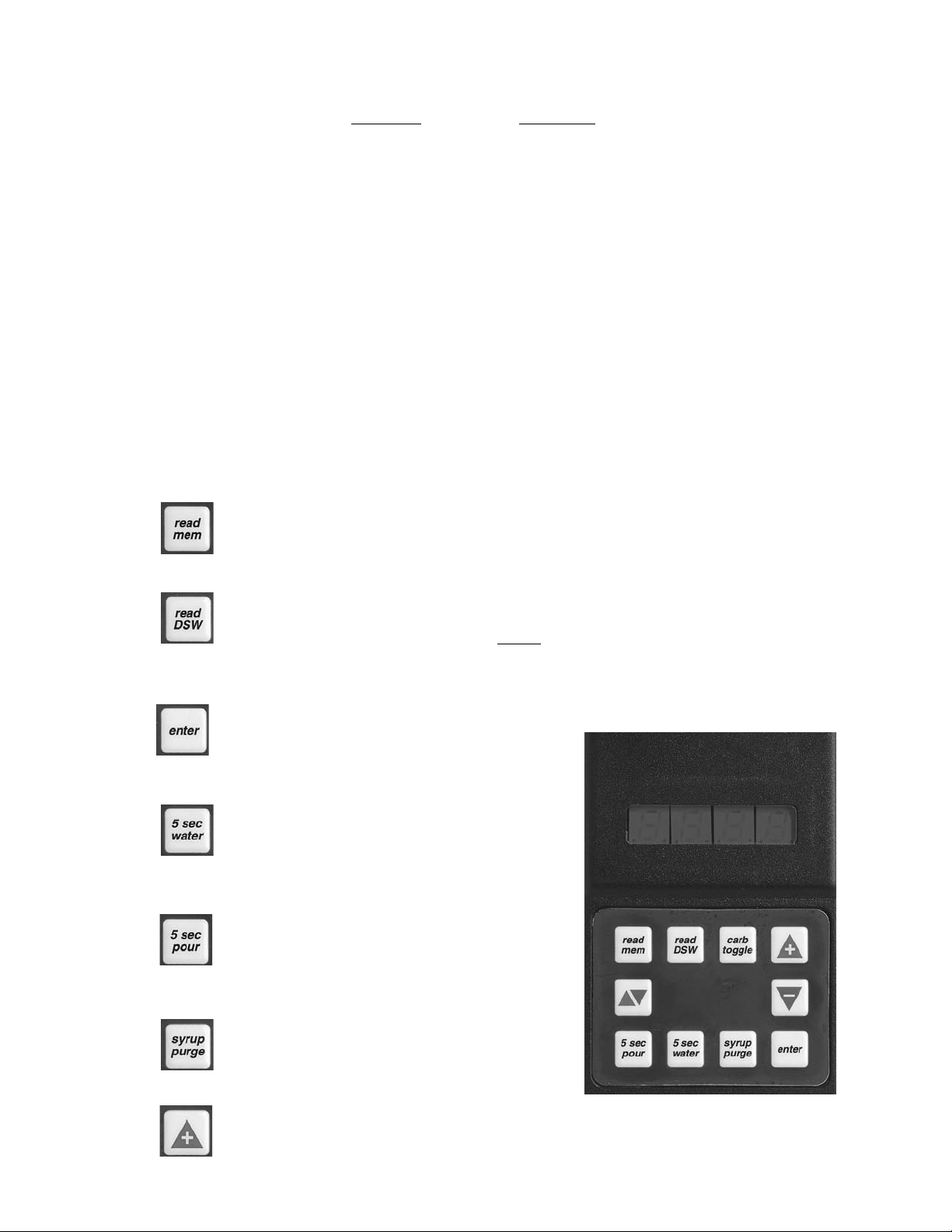
B. Programmer Operating Procedures
1. Connecting
a. Remove the ID panel from the front of the valve.
b. Insert the programmer's 10-pin connector into the ID Panel plug on the front of the
circuit board.
c. When properly connected, the programmer will run a self diagnostic test. The display
will show all "8"s with the decimal points lighted. After three (3) seconds, the display
indicates the setting of the dip switches.
d. If the programmer does not run its diagnostic test properly, disconnect it and try
plugging it in again. If the programmer still fails, replace the programmer.
2. Functions
Read Memory:
Press this button to read and display the current settings programmed into the valve
memory (i.e., S/W revision, ratio, and carb/non carb settings).
Read Dip Switches:
Press this button to read the dip switch settings (applies only to valves manufactured
before July 1997).
NOTE
Dip switches were used on some field test valves (refer to 28-0301, 12/20/95).
Write Memory:
Press this button to write the programmer’s displayed ratio and carbonation settings into
the valve’s memory.
Timed 5 Second Water:
Press this button to pour water for five (5)
seconds. The programmer will display the ratio,
the counts from the flowmeter, the flow rate in
oz/sec, and the flow rate in ml/sec.
Timed 5 Second Pour:
Press this button to dispense a five (5) second
pour of water and syrup for ratio testing. When
complete, the programmer displays the ratio,
carbonation settings, and total Flowmeter counts.
Syrup Purge:
Press and release to dispense a six (6) second
syrup purge. Continue holding to purge syrup
from system.
Ratio + (Plus):
Pressing this button will increase the ratio
number on the display.
Hand Held Programmer
Figure 1
Page 11

5
Ratio - (Minus):
Pressing this button will decrease the ratio number on the display.
Carb Toggle:
Pressing this button will toggle the carbonation setting from carbonated “C” to plain
water “n” (non-carbonated).
Pour/Stop:
Press this button to manually pour a mixed drink. This button will also stop a timed pour.
Setting the Ratio/Carbonation
1. Connect the programmer to the Valve.
2. Press the “Read Mem” button.
3. Press the “Ratio +” or the “Ratio -” key until the desired ratio is displayed.
4. Verify the drink type. Press “Carb Toggle”to select “C” for carbonated or “n” for
non-carbonated.
5. Press the “Enter” button to program the valve with the setting on the display
6. Verify Ratio by pressing “Read Mem”.
7. Disconnect the programmer.
1.15 PORTION CONTROL
A. Programming Procedures
The following procedures describe the operation and programming of portion control ID panels
for the Volumetric Valve.
B. Operation
1. Cup buttons are Small, Medium, Large,
Extra-Large.
2. Press and release the desired cup size.
Valve will fill cup as programmed (see
below).
3. Pour/Cancel Button
a. Push and release to cancel or stop
valve dispensing.
b. Push and hold for continuous pour.
4. Water Button
Push and hold for continuous water pour.
Valve will dispense carbonated or
non-carbonated water, depending on its
location on the dispenser.
C. Teach and Learn Portion Control
Programming
In this mode, the valve “learns” the steps to
fill each cup size, including the top off delay
time. When activated, the valve dispenses
the appropriate drink volume. Then, if a top
off has been entered, it will pause for the
programmed length of time. Finally, the
valve will dispense the correct top off
amount.
Portion Control, cup Buttons, Overlay
Figure 2
Portion Control, cup Buttons, Overlay
with Water
Figure 3
Small
Cup Button
Medium
Cup Button
Large
Cup Button
Pour/Stop
Button
Small
Cup Button
Water
Button
Medium
Cup Button
water
Large
Cup Button
Pour/Stop
Button
Extra-Large
Cup Button
Extra-Large
Cup Button
Page 12

6
D. Initial Install Procedure
1. Simultaneously, press and hold the small cup button and the extra-large cup button
switches on the portion control until the LED light in center of module starts blinking, then
release switches. The blinking LED indicates that the set mode is active.
2. Put desired amount of ice in cup, place cup under valve and push selected size button
(small, medium, large, or extra-large). Hold button in until cup fills to desired portion, then
release button.
3. Top off: If a top off is not needed, go to Step 4. Wait for foam to settle, then actuate
button again to top off.
NOTE
Only one (1) top off is allowed.
4. Repeat Steps 2 and 3 for other drink sizes. Go to Step 5 to exit program mode.
5. Press and release pour/stop button to return the portion control to the operational mode.
Blinking LED light will go out.
6. Repeat Steps 1 through 5 for remaining valves.
E. To Change Dispense Size
Use procedures in the Initial Install Procedure discussed above; it is not necessary to reprogram
every size.
F. Calibrated Cup Portion Control Programming
In this mode, the valve adds the volume from each programming step to the total drink size.
When activated, the valve dispenses the total drink without pauses.
1. Simultaneously, press and hold the small and large buttons (see Figures 2 and 3) on the
portion control until the LED light in the center starts blinking, then release switches.
2. Place volume cup under nozzle of valve to be calibrated.
3. Press appropriate size switch and fill volume cup to a point just short of the calibration mark
on the volume cup. The LED will stay lighted constantly while programming an individual
cup size.
4. Let foam settle, jog size switch until liquid reaches the calibration mark on the volume cup.
5. Press pour/stop button to end programming for selected cup size. LED will start blinking.
6. To program another cup size, repeat Steps 2 through 5, this section.
7. To exit the calibrated cup programming mode, press the pour/stop button when the Led is
blinking. If the LED is lighted constantly, press the pour/stop button once to end the cup size
program (LED starts blinking) and again to exit the program mode (LED off).
2. SCHEDULED MAINTENANCE
CAUTION
DO NOT USE ANY POWDERS OR ABRASIVE CLEANING COMPOUNDS WHICH CAN DAMAGE THE
FINISH OF THE DISPENSER.
2.1 DISPENSER
A. DAILY
1. Remove the nozzle and diffuser from each valve. Clean as directed in the Nozzle and
Diffuser Section.
2. Remove the cup rest and wash in warm soapy water.
3. Pour warm soapy water into the drip tray and wipe with a clean cloth.
4. With a clean cloth and warm soapy water, wipe off all exterior surfaces of the unit.
5. Reinstall the cup rest, valve diffusers and valve nozzles.
Page 13

7
B. WEEKLY
CAUTION
THE WATER BATH COMPARTMENT MUST BE FILLED WITH WATER BEFORE PLUGGING
IN THE UNIT, OTHERWISE THE COMPRESSOR DECK AND CONDENSER FAN MAY NOT
OPERATE PROPERLY.
Remove the unit’s bonnet and check the level of water in the water bath. Replenish as required,
and reinstall the bonnet.
NOTE
Do NOT use distilled water to fill water bath.
C. MONTHLY
1. Unplug the dispenser from it’s power source.
2. Remove the nozzle and diffuser from each valve. Clean as directed in the Nozzle and
Diffuser Section.
3. Remove the bonnet, and clean the dirt from the unit’s condenser using a soft brush.
4. Reinstall the bonnet and plug in the unit.
D. EVERY SIX (6) MONTHS
Clean and sanitize the unit using the appropriate procedures outlined in Section 3 of this
manual.
E. YEARLY
1. Clean water bath interior, including evaporator coils and refrigeration components.
2. Clean the entire exterior of the unit.
3. Sanitize syrup lines.
2.2 VOLUMETRIC VALVE CLEANING AND SANITIZING PROCEDURES
A. Daily Nozzle/Diffuser Cleaning (See Figure 4)
Use the following procedures to clean the nozzle, and the diffuser assembly, each day:
1. Remove nozzle by twisting it counter-clockwise and pulling it down.
2. Pull the diffuser assembly down to remove it from the valve.
3. Wash the nozzle and diffuser with warm water.
4. If needed, apply 111 lubricant to the o-ring on the diffuser assembly. Then, carefully press
it into the diffuser mounting area on the underside of the valve.
5. Make certain the nozzle o-ring, is in place around the nozzle mounting area on the valve. If
necessary, slide a new nozzle o-ring onto the nozzle mounting area.
6. Install the nozzle by inserting it into the bottom plate and twisting it clockwise to lock it in
place.
Nozzle/Diffuser
Figure 4
B. Monthly Nozzle/Diffuser Sanitizing
Use the following procedures to sanitize the nozzle, and
the diffuser assembly, once a month.
1. Cleaning Solution
Prepare a caustic-based (low sudsing, non-perfumed,
and easily rinsed) detergent solution and clean,
potable water at a temperature of 90
o
to 110oF. The
cleaning solution should be 2% sodium hydroxide.
2. Sanitizing Solution
Prepare a chlorine solution (less than pH 7.0)
containing 50 PPM available chlorine with clean,
potable water at a temperature of 90
o
to 110oF. Any
sanitizing solution may be used as long as it is
prepared in accordance with the manufacturer’s
written recommendations and safety guidelines, and
provides 50 PPM available chlorine.
Diffuser
Assembly
Nozzle
Page 14

3. Cleaning Procedure
CAUTION
BE CAREFUL NOT TO GET SANITIZING SOLUTION ON THE CIRCUIT BOARD.
1. Disconnect power, so the valve will not be inadvertently activated while cleaning.
2. Remove nozzle by twisting it counter-clockwise and pulling it down.
3. Pull the diffuser assembly down to remove it from the valve.
4. Wash the nozzle and diffuser with the cleaning solution.
5. Immerse the nozzle and diffuser in a bath of the sanitizing solution for 15 minutes.
6. While the parts are in the sanitizing solution, visually inspect around the nozzle
mounting area on the valve for syrup residue. Using a cloth or nozzle brush and warm
water, clean this area.
7. Wipe off the dispensing lever and any other areas that may have been splashed by
syrup.
8. Wearing sanitary gloves, remove, drain, and air dry the nozzle and diffuser.
9. Wearing sanitary gloves, carefully press the diffuser into the mounting area on the
underside of the valve.
10. Make certain the nozzle o-ring, is in place around the nozzle mounting area on the
valve. If necessary, slide a new nozzle o-ring onto the nozzle mounting area. (Wear
sanitary gloves while handling the o-ring.)
11. Wearing sanitary gloves, install the nozzle by inserting it into the bottom plate and
twisting it clockwise to lock it in place.
12. Connect power and replace cover. Valve is ready for operation.
13. Draw drinks to flush residual sanitizing solution. Taste the beverage to verify that there
is no off taste. If an off taste is found, additional flushing may be required.
C. Valve and System Sanitizing
The complete valve and dispenser system must be sanitized during initial installation. Follow
the manufacturer’s instructions when scheduling and conducting dispenser sanitizing. The
valve must be sanitized once every two weeks. The valve may remain on the dispensing tower
during the sanitizing process.
3. DISPENSER CLEANING AND SANITIZING
CAUTION
BECAUSE OF DIFFICULTY IN RINSING, DETERGENT SOLUTIONS SHOULD NOT BE
INTRODUCED INTO THE CARBONATOR.
3.1 AMBIENT PROCESS
A. The ambient process is the most common method for cleaning and sanitizing dispenser
equipment. The detergent should be caustic-based and the sanitizer should be a low pH (7.0)
chloride solution.
B. Disconnect syrup containers and remove product from tubing by purging with carbon dioxide.
C. Rinse the lines and fittings with clean room temperature water to remove all traces of residual
product.
D. Fill lines with a caustic-based (low-sudsing, non-perfumed, and easily rinsed) detergent solution.
The solution should be prepared in accordance with the manufacturers recommendations, but
should be at least two (2) percent sodium hydroxide. Make sure the lines are completely filled
and allow to stand for at least 10 minutes.
E. Flush the detergent solution from the lines with clean water. Continue rinsing until testing with
phenolphthalein shows that the rinse water is free of residual detergent.
F. Fill the lines with a low pH (7.0) chlorine solution containing at least 50 PPM (50 mg/L) chlorine.
Make sure that lines are completely filled and allow to stand for 10 minutes.
G. Reconnect syrup containers and ready Unit for operation.
H. Draw drinks to refill lines and flush the chlorine solution from the dispenser.
NOTE
Please note that a fresh water rinse cannot follow sanitization of equipment. Purge only with the
end use product. This is an NSF requirement.
8
Page 15

WARNING
REMOVE SANITIZING SOLUTION FROM DISPENSER AS INSTRUCTED. RESIDUAL
SANITIZING SOLUTION LEFT IN SYSTEM COULD CREATE A HEALTH HAZARD.
I. Test dispenser in normal manner for proper operation. Taste dispensed product to ensure there
is no off-taste. If off-taste is found, additional flushing of dispensing system may be required.
3.2 ALTERNATE CLEANING AND SANITIZING AGENTS
A. The above approach (Section 3.1) to cleaning and sanitizing the dispenser is strongly
recommended. However, the Division Quality Assurance Manager may approve the following
cleaning and sanitizing agents.
B. Chlorinated alkaline detergents. These compounds may be used as the cleaning agent, but
may not be used as combined cleaner/sanitizer.
C. Iodophors may be substituted for chlorine as the sanitizing agent.
CAUTION
IODOPHORS AND QUATERNARY AMMONIUM COMPOUNDS (QUATS) ARE BROAD
CLASSES OF COMPOUNDS. SOME MEMBERS OF EACH GROUP CAN CAUSE SERIOUS
PROBLEMS WITH FOAMING, DISTORTION OR DISCOLORATION OF POLYMERIC PARTS,
POOR RINSIBILITY, AND OFF TASTE. THE RINSIBILITY AND OFF TASTE PROBLEMS HAVE
BEEN ESPECIALLY PREVALENT WITH QUATS. BECAUSE OF THE POTENTIAL PROBLEMS,
APPROVAL MUST BE GRANTED BY THE DIVISION QUALITY ASSURANCE MANAGER TO
SPECIFIC COMPOUNDS. THIS APPROVAL SHOULD BE BASED UPON TESTING IN THE
LABORATORY.
D. Quaternary ammonium compounds may be used as a combined cleaner-sanitizer but are
generally not recommended. These compounds are not to be utilized at concentrations
exceeding 200 PPM (200 mg/L), or that concentration specified in local regulations, which ever
is lower.
4. TROUBLESHOOTING
TROUBLE
CAUSE REMEDY
4.1 Water leakage around A. Damaged, missing, or A. If damaged, replace. If improperly
nozzle. improperly installed o-ring installed, adjust.
above nozzle.
4.2 Miscellaneous leakage. A. Gap between parts. A. Tighten appropriate retaining
screws.
B. Damaged or improperly B. Replace or adjust appropriate
installed o-rings. o-rings.
4.3 Water leakage - Valve. A. Screw(s) loose. Water A. Tighten screw(s).
solenoid or flowmeter
screws turn easily.
B. Water leaks past o-ring, after B. Replace o-ring.
screws have been tightened.
C. Crack is visible in flowmeter C. Replace flowmeter assembly.
body.
D. Water leaks through nozzle. D. Remove debris from water
Debris in water solenoid. solenoid.
E. Water continues to leak E. Replace valve.
after above items have been
checked. Valve body broken.
4.4 Syrup leakage - Valve. A. Screw(s) loose. Syrup body A. Tighten screw(s) to 9 inch-pounds.
or syrup retainer screws
turn easily.
B. Water leaks past o-ring, after B. Replace o-ring.
screws have been tightened.
(Section 4.4 continued next page)
9
Page 16

(Section 4.4 continued from previous page)
C. Crack is visible in syrup body. C. Replace syrup body assembly.
D. Syrup leaks through nozzle. D. Remove debris from syrup
Debris in syrup solenoid. solenoid.
E. Syrup continues to leak E. Replace valve.
after above items have been
checked. Valve body broken.
4.5 Insufficient water flow. A. Shutoff on mounting block not A. Open shutoff fully.
fully open.
B. Foreign debris in water pump B. Remove water pump strainer and
strainer. clean.
C. Insufficient incoming supply C. Verify incoming supply water
water pressure. pressure is a minimum of 10 PSI.
4.6 Insufficient syrup flow. A. Insufficient CO
2 pressure to A. Adjust CO2 pressure to 80 PSI
BIB pumps. (minimum 70 PSI) for BIB pumps.
B. Shutoff on mounting block not B. Open shutoff fully.
fully open.
4.7 Drink ratio incorrect A. Syrup restrictor incorrectly set. A. Check location of restrictor. The
(Weak or Strong) - restrictor must be in and up for diet
Valve BIB applications. Restrictor must
be down and out for non-diet
drinks. Position restrictor correctly.
B. Water flow more than (see B. Flow washer bad (if installed).
table just below). If installed, Replace flow washer assembly, or
flow washer is installed install one if needed.
correctly.
WATER FLOW MORE THAN:
Valve Specification Maximum Water Flow Rate
88.7 ml/sec (3.0 ounces/second) 80.0 ml/sec (2.7 ounces/second)
66.6 ml/sec (2.25 ounces/second) 60.0 ml/sec (2.1 ounces/second)
44.4 ml/sec (1.5 ounces/second), as shipped 40.0 ml/sec (1.4 ounces/second)
C. Insufficient syrup pressure. C. Increase dispensing system syrup
Run syrup purge test on hand pressure.
held programmer. Output
syrup should be approximately
3 ounces.
D. Syrup may be obstructed. D. Disassemble syrup side and
Incorrect ratio measurement remove obstruction.
after circuit board replaced.
E. Flowmeter malfunctioning E. Replace flowmeter assembly.
after all other items above
have been checked.
4.8 Valve pours erratically. A. Incoming water and/or syrup A. Check pressure and adjust.
supply not at minimum flowing
pressure.
B. Solenoid, flowmeter, and/or B. Insert connectors until locking tabs
pushbutton connectors not engage.
completely plugged into
circuit board.
C. Pushbutton malfunctioning. C. Replace pushbutton.
(Section 4.8 continued next page)
TROUBLE
CAUSE REMEDY
10
Page 17

(Section 4.8 continued from previous page)
D. Circuit board covered with D. Unplug all connectors. Dry out and
water or syrup and connectors blow dry. Shake water out of plug.
are wet. Reinsert connectors until locking
tabs engage.
E. Valve still pours erratically E. Replace malfunctioning circuit
after pushbutton replaced and board.
connectors have been dried
and cleaned.
F. Hissing sound heard out of F. Air in lines. Continue to pour until
valve. lines are purged of air.
4.9 No product dispensed A. Water and syrup shutoffs on A. Open shutoffs fully.
when valve activated. mounting block closed or not
fully open. Programmer lights
up when plugged in.
B. The key switch is in the OFF B. Turn key switch to ON position.
position.
C. Cup lever arm or ID panel C. Repair.
actuator on valve is not
actuating the switch.
D. Electricity not reaching valve. D. Check electric current supplied to
valve. Insure 24 volt supply is
plugged in. If voltage is adequate,
check solenoid coil and switch, and
replace if necessary.
E. Improper or inadequate water E. Remove valve from mounting block,
or syrup supply. open shutoffs slightly and check
water and syrup supply. If no
supply, check dispenser for
freeze up or other problems.
F. Transformer failure. F. Reset transformer circuit breaker.
If breaker pops again refer to
Section 4.25.
G. Pushbutton or portion control G. Replace ID panel.
malfunctioning. Programmer
can activate valve.
H. Programmer does not light up H. Circuit Board malfunctioning.
and 24 volt supply connected. Replace circuit board.
I. “5 sec water” button on I. Soda and front syrup solenoid
programmer dispenses small wires plugged into wrong
amount of syrup. connector. Connect soda and
front syrup to correct connector.
J. Programmer lights up, but J. Water solenoid malfunctioning.
does not dispense water with Replace water solenoid.
“5 sec water”. Shutoffs are
open.
K. A new ratio cannot be entered K. Circuit board malfunctioning.
by the programmer. Replace circuit board.
L. Circuit board misaligned. L. Ensure circuit board is aligned and
Lever not making contact with screw circuit board down all the
circuit board sensor. way.
4.10 Water only dispensed; A. Water or syrup shutoff on A. Open shutoff fully.
no syrup; or syrup only mounting block not fully open.
dispensed; no water. B. Improper or inadequate B. Remove valve from mounting block
water or syrup supply. and open shutoffs slightly and
check water and syrup supply. If
no supply, check dispenser for
freeze-up or other problems.
Ensure BIB connection is engaged.
(Section 4.10 continued next page)
11
TROUBLE CAUSE REMEDY
Page 18

(Section 4.10 continued from previous page)
C. BIB supply too far from C. Check that BIB supply is within
dispenser. 1.83 meters [six (6) feet] of the
dispenser.
D. CO
2 pressure too low. D. Check the CO2 pressure to the
pump manifold to ensure it is
between 70-PSI.
E. Stalled or inoperative BIB E. Check CO2 pressure and/or replace
pump. pump.
F. Kinked line. F. Remove kink or replace line.
G. Water only dispensed. Coils G. Open syrup shutoff on mounting
click when activated by block.
programmer “syrup purge”.
H. Out of syrup. “Syrup purge” H. Replace BIB or figal.
draws no syrup and shutoff
is open.
I. No clicking sound when “syrup I. Plug in syrup solenoid.
purge” is activated.
J. Flow rate zero (0) after J. Flowmeter is unplugged. Plug in
programmer “5 sec water” flowmeter.
pour.
K. Flowmeter connector wet. K. Unplug. Dry connector. Shake
Flow rate zero (0) after water out of plug. Reinsert
programmer “5 sec water” connector.
pour. Circuit board wet.
L. Programmer does not light L. Replace circuit board.
up when plugged in. Circuit
board malfunctioning.
M. Flowmeter rotor is obstructed, M. Remove obstruction or replace
does not urn freely. Flow rate flowmeter.
zero (0) after programmer
“5 sec water” pour.
N. Flow rate zero (0) after N. Replace flowmeter assembly.
programmer “5 sec water”
pour. Flowmeter sensor bad.
O. No clicking sound when “syrup O. Replace syrup solenoid.
purge” is activated and coils
are properly connected. Syrup
solenoid bad.
P. Coils click when “syrup P. Disassemble syrup side and
purge” is activated, shutoff is remove obstruction.
open, and syrup supply is full.
4.11 No water just syrup. A. Low level. A. Add water until it flows from
(Ice bank grew to water overflow tube.
inlet line to carbonator B. Unit not level. B. Level unit and add water.
tank.) C. Syrup in water bath. C. Melt ice bank and remove all water.
Refill. Locate possible syrup leak
area and repair.
D. Water cage is out of position. D. Reposition water cage.
E. PCB relay sticking. E. Check continuity of compressor
relay. Compressor should time-out
in five (5) minutes.
F. Refrigerant leak. F. Find leak and recharge unit. (If
unit is not frozen.)
G. Check water supply. G. Turn on water and shut unit OFF,
then ON, to reset carbonator.
H. Carbonator timed out. H. Turn unit OFF then ON to reset
carbonator.
I. PCB malfunctioning. I. Replace PCB.
TROUBLE CAUSE REMEDY
12
Page 19

4.12 Valve will not shut off. A. Cup lever may be damaged, A. Correct or replace lever arm,
sticking, or binding. Top end and/or lever spring.
of lever arm does not return
to back of valve.
B. Switch not actuating freely. B. Check switch for free actuation.
C. Valve stops when panel is C. Replace panel.
unplugged from circuit board.
pushbutton/portion control
malfunctioning.
D. Valve pours with lever arm D. Circuit board malfunctioning.
retracted, or pushbutton or Replace circuit board.
portion control is unplugged.
E. Circuit board covered with E. Unplug. Dry out connector. Shake
water or syrup. Moisture in water out of plug. Reinstall when
plug (pushbutton, programmer) dry.
on front of circuit board.
4.13 Syrup only dispensed. A. Improper water flow to A. Check for water flow to dispenser
No water, but CO2 gas dispenser. (see Section 4.5).
dispensed with syrup. B. Carbonator pump motor has B. Reset by turning the unit OFF and
(Valve cycles on and timed out. and then ON by using the ON/OFF
off quickly.) switch on top of the unit or
unplugging unit momentarily.
C. Liquid level probe not C. Check connections of liquid level
connected properly to PCB. probe to PCB assembly.
D. Faulty PCB assembly. D. Replace PCB assembly.
E. Faulty liquid level probe. E. Replace liquid level probe.
F. Water bath frozen. F. Thaw water bath and repair faulty
component. (See refrigeration
related symptoms.)
G. Water line frozen. G. Refer to Section 4.16.
4.14 Excessive foaming. A. Incoming water or syrup A. Correct prior to dispenser.
temperature too high. Consider larger dispenser or
pre-cooler.
B. CO
2 pressure too high. B. Adjust CO
2 pressure downward, but
not less than 70 PSI.
C. Nozzle and diffuser not D. Remove and reinstall properly.
properly installed.
D. Nozzle and diffuser not clean. D. Remove and clean.
E. Air in BIB lines. E. Bleed air from BIB lines.
F. Poor quality ice. F. Check quality of ice used in drink.
G. High beverage temperature. G. Check refrigeration system.
H. Diet restrictor setting incorrect. H. Restrictor must be set “up and in”
for diet BIB drinks. For all other
drinks, restrictor must be set “out
and sideways”. Set correctly.
I. Hissing sound heard from I. Continue to pour until air is
valve. Air is in system. purged from lines.
J. Water flow rate greater than J. Replace flow washer assembly, or
2.7 oz/sec. install flow washer assembly (if not
previously installed).
4.15 Water continually A. Loose water connection(s). A. Tighten water connections.
overflows from water B. Flare seal washer leaks. B. Replace flare seal washer.
bath into drip tray. C. Faulty water coil. C. Replace water coil.
13
TROUBLE CAUSE REMEDY
Page 20

4.16 Compressor starts and A. PCB malfunctioning or faulty A. Disconnect ice band probe from
continues to run until ice bank probe. PCB.
freeze up and will not 1. If compressor continues to run,
cut off. replace PCB.
2. If compressor stops, replace
ice bank probe.
B. Ice bank probe positioned B. Check positioning of ice bank
improperly. probe, and replace if needed.
C. Ice bank probe shorted to ground. C . Replace ice bank probe.
NOTE: First check to ensure that the three (3) minute carbonator timer has not timed out. Turn unit off
and then on. If the pump shuts off in less than 30 seconds, the dispenser is not frozen.
4.17 Warm drinks. A. Restricted airflow. A. Check clearances around sides,
top, and inlet of unit. Remove
objects blocking airflow through
grill.
B. Dispenser connected to hot B. Switch to cold water supply.
water supply.
C. Refrigeration system not C. Refer to Sections 4.18 - 4.22.
running.
D. Refrigerant leak. D. Repair and recharge.
E. Condenser fan motor not E. Replace condenser fan motor.
working.
F. Dirty condenser. F. Clean condenser.
G. Dispenser capacity exceeded. G. Add pre-cooler or replace with
larger dispenser.
4.18 Compressor does not A. There is a five (5) minute A. Allow for five (5) minute delay to
start (no hum), compressor and condenser lapse.
condenser fan motor fan delay.
does not run and no B. Ice bank probe not B. Fill water reservoir until water flows
ice bank. completely submerged. from overflow tube.
C. Circuit breaker or fuse tripped. C. Reset breaker or replace fuse. If
problem persists:
1. Determine reason and correct.
2. Electrical circuit overloaded;
switch to another circuit.
D. Inadequate voltage. D. Measure voltage across common
and run terminal on compressor.
Voltage must not drop below 90%
of rated voltage.
E. PCB malfunctioning. E. Replace PCB assembly.
F. Incorrect wiring. F. Refer to wiring diagram and correct.
G. Faulty ice bank probe. G. Replace ice bank probe.
H. Transformer failure. H. Reset transformer circuit breaker. If
breaker pops again, refer to
Section 4.27.
I. Ice bank probe not connected I. Connect ice bank probe to PCB.
properly to PCB.
4.19 Compressor does not A. Compressor relay or overload A. Replace compressor relay or
start (no hum), but malfunctioning. overload.
condenser fan motor B. Inadequate voltage. B. Measure voltage across common
runs. and run terminal on compressor.
Voltage must not drop below 90%
of rated voltage.
C. Incorrect wiring. C. Refer to wiring diagram and correct.
D. Compressor malfunctioning. D. Replace compressor.
4.20 Compressor does not A. Inadequate voltage. A. Measure voltage across common
start but hums. and run terminal on compressor.
Voltage must not drop below 90%
of rated voltage.
(Section 4.20 continued next page)
14
TROUBLE CAUSE REMEDY
Page 21

(Section 4.20 continued from previous page)
B. Incorrect wiring. B. Refer to wiring diagram and correct.
C. Starting relay malfunctioning. C. Replace starting relay. Be sure to
use correct relay. Failure to use
correct relay will cause compressor
failure.
D. Compressor malfunctioning. D. Replace compressor or deck.
4.21 Compressor starts but A. Inadequate voltage. A. Measure voltage across common
does not switch off start and run terminal on compressor.
winding (will run for only B. Incorrect wiring. B. Refer to wiring diagram and correct.
a few seconds before C. Starting relay malfunctioning. C. Replace starting relay. Be sure to
internal overload use correct relay. Failure to use
switches compressor correct relay will cause compressor
off). failure.
4.22 Compressor starts and A. Dirty condenser. A. Clean the condenser.
runs a short time but B. Insufficient or blocked air flow. B. Remove all obstructions and allow
shuts off on overload. for minimum clearances of eight (8)
inches (20.3 cm) over top.
C. Inadequate voltage. C. Measure voltage across common
and run terminal on compressor.
Voltage must not drop below 90%
of rated voltage.
D. Incorrect wiring. D. Refer to wiring diagram and correct.
E. Defective condenser fan motor. E. Replace condenser fan motor.
F. Refrigerant leak. F. Repair and recharge.
G. Compressor malfunctioning. G. Replace compressor.
4.23 Compressor runs A. Low water level in water bath. A. Add water to water bath until water
normally, but water line runs out of overflow into drip tray.
is frozen. B. Syrup in water bath. B. Drain water from water bath and
refill with clean water.
C. Water cage is out of position. C. Reposition water cage.
D. Low refrigerant charge/ D. Find and repair leak. Recharge
slow refrigerant leak system.
4.24 Compressor cycles A. PCB malfunctioning A. Replace PCB assembly.
on and off frequently B. Defective probe. B. Replace probe.
during the initial
pulldown and/or
normal operations.
4.25 Circuit breaker popping. A. Valve wire harness shorted to A. Detect short by disconnecting input
itself or to faucet plate. faston to keylock and single pin
connector. Restore power if
breaker doesn’t pop. Then valve
wire harness is shorted, if OK,
Re-connect.
B. PCB is bad. B. Detect short by disconnecting J1
connector (24 VAC input) from
PCB. Restore power, if breaker
doesn’t pop. Then replace PCB. If
breaker does pop, then PCB is
OK. Reconnect J1 connector.
C. Secondary wire harness is C. If it does not pop, locate short in
bad. secondary harness between
transformer, PCB and valve wire
harness.
D. Transformer failure. D. Detect short by disconnecting both
transformer fastons and restore
power. If breaker does pop, replace
transformer.
15
TROUBLE CAUSE REMEDY
Page 22

4.26 BIB pump does not A. Out of CO2, CO2 not turned A. Replace CO2 supply, turn on CO2
operate when on, or low CO2 pressure. supply, or adjust CO2 pressure to
dispensing valve is 70-80 PSI.
opened. B. Out of syrup. B. Replace syrup supply.
C. BIB connector not tight. C. Fasten connector tightly.
D. Kinks in syrup or gas lines. D. Straighten or replace lines.
4.27 BIB pump operated but A. Leak in syrup inlet or outlet A. Replace line.
no flow. line.
B. Defective BIB pump check B. Replace BIB pump.
valve.
4.28 BIB pump continues to A. Leak in suction line. A. Replace line.
operate when bag is B. Leaking o-ring on pump inlet B. Replace o-ring.
empty. fitting.
4.29 BIB pump fails to restart A. BIB connector not on tight. A. Tighten BIB connector.
after bag replacement. B. BIB connector is stopped up. B. Clean out or replace BIB connector.
C. Kinks in syrup line. C. Straighten or replace line.
4.30 BIB pump fails to stop A. Leak in discharge line or A. Repair or replace discharge line.
when dispensing valve fittings.
is closed. B. Empty BIB. B. Replace BIB.
C. Air leak on inlet line or bag C. Repair or replace.
connector.
4.31 No product out light. A. Burned-out lamp. A. Replace lamp.
B. Faulty wiring or pressure B. Repair or replace.
switch in product line.
4.32 Low or no carbonation. A. Low or no CO2. A. Check CO2 supply. Adjust CO2
pressure to 70 PSI.
B. Excessive water pressure. B. Water regulator should be set at
50 PSI.
C. Worn or defective carbonator C. Replace carbonator pump.
pump.
16
TROUBLE CAUSE REMEDY
Page 23

17
NOTES
Please refer to the Lancer web site (www.lancercorp.com) for
information relating to Lancer Installation and Service Manuals,
Instruction Sheets, Technical Bulletins, Service Bulletins, etc.
Page 24

18
5. ILLUSTRATIONS, PARTS LISTINGS, AND WIRING DIAGRAMS
5.1 800 CED - CABINET ASSEMBLY
31
30
30B
30A
30E
30D
30C
16
24
17
25
23
22
18
21
26
29
19
33
20
8
28
27
12
30B
32
33
34
35
37
9
10
8
11
8
5
6
8
36
1
2
3
4
15
14
13
14
7
Page 25

ITEM P
ART NO. DESCRIPTION
- 82-2634 Cabinet Assy, 800 CED
1 51-5481 Wrapper Assy
2 06-0075-01 Nameplate, Serial Number
3 06-0075-84 Nameplate, 804 Model
4 04-0072 Rivet
5 04-0545 Screw, 8 - 16 x .780, Plastite
6 51-0494/01 Leg Bracket Assy
7 05-1280 Leg
8 04-0061 Screw, 8 - 18 x .375 AB
9 04-0429 Rivet
10 04-0187 Spacer, SS
11 30-0587 Bracket, Drip Tray, Right
12 30-0588 Bracket, Drip Tray, Left
13 03-0115 Clip, Retaining
14 04-1002 Screw, 4 - 40 x 0.250, Rolok
15 82-1422 Drain Assy
16 05-0889 Drip Tray
17 23-1164 Cup Rest, Short
- 23-1163 Cup Rest, Tall
18 30-6883 Splash Plate
19 06-0851 Label, Overflow
20 30-6999 Front Support, Painted
21 04-0074 Nut, Clip
22 04-0068 Screw, 10 - 24 x 0.375 FH,
Machine
23 11-0015 Socket, Housing
24 13-0005 Bushing
25 30-7503 Faucet Plate, 4 Valve, 3 Way
26 52-2155 Harness Assy
27 03-0036 Clip, Retaining
28 50-0256 Insulation, Front
29 50-0258 Insulation, Comb
30 82-2709 Bonnet Assy with Graphics and Filter
(Contact Customer Service)
30A REF Graphic, Front (Contact Customer
Service)
30B REF Graphic, Side (Contact Customer
Service)
30C 23-1145 Bonnet Assy, Extended, Red, 800
30D 30-7544 Bracket, Filter
30E 81-0495 Filter
31 05-0786 Plug, Bonnet
32 50-0260 Insulation, Back
33 50-0255 Insulation, Side
34 82-2258 Tank Assy, Foamed
35 06-0881 Label, Key Switch
36 12-0097 Key Switch
37 07-0490 Cover Plate
19
5.1 800 CED - CABINET ASSEMBLY (CONTINUED)
Page 26

5.2 800 CED - REFRIGERATION DECK ASSEMBLY
20
27
5
11
34
33
38
10
10
35
26
36E
36
14G
36C
36F
36A
36G
32
36B
14A
37
10
40
41
31
29
36D
30
6
28
26
45
44
19
22
21
20
23
24
25
18
7
15
3
14B
14
14D
14F
8
9
14E
39
14C
43
12
13
10
17
42
16
6
1
7
2
4
Page 27

ITEM PART NO. DESCRIPTION
- 82-2692 Deck Assy, Refrig.,R-134a,
100V/50-60Hz
1 51-5562/01 Sub Assy, Compressor Deck
2 50-0257/01 Insulation, Compressor Deck
3 04-0063 Washer, Flat
4 89-0014 Cover, Hole
5 23-0956/03 Evaporator Coil Assy
6 51-0068 Handle
7 04-0574 Washer
8 52-2174 Control Housing Assy
- 26-0374 Capacitor
9 06-2114 Label, Wiring Diagram
10 04-0504 Screw, 8 - 18 x 0.375
11 06-0080-01 Label, Nameplate
12 02-0041 Seal
13 25-0066 Transformer, 100V/50-60Hz
14 52-2160 Motor Assy, Agitator, 100V/50-60Hz
14A 30-5113/01 Bracket, Agitator
14B 05-0495/01 Propeller, 2.062 DIA
14C 05-0502 Propeller, 2.250 DIA
14D 91-0128 Motor, Agitator, 25W, 100V/50-60Hz
14E 02-0032 Washer
14F 06-2113 Label, 100V/50-60Hz, 25W
14G 04-0059 Screw
15 02-0040 Seal, Extrusion
16 04-0032 Nut, Nylok, 1/4 - 20
17 04-0033 Washer, Flat (0.281 ID)
18 88-0053 Compressor, R-134a, 100V/50-60Hz
19 12-0341 Relay, R-134a, 100V/50-60Hz
20 12-0342 Overload, R-134a, 100V/50-60Hz
21 13-0006 Cover, Terminal
22 03-0040 Bale Strap
23 02-0114 Grommet
24 04-0537 Washer, Flat (0.467 ID)
25 03-0150 Retainer, Clip
26 47-0344 Tube, Process
27 47-1233/01 Tube, Compressor (Hi Side)
28 47-1718 Tube, Return (Lo Side)
29 51-0061 Accumulator
30 50-0211 Boot
31 50-0205 Insulation, Tube
32 50-0159 Insulation, Tube
33 23-0985 Condenser, R-134a
34 30-5881 Shroud, Fan, Top
35 30-5882 Shroud, Fan, Bottom
36 52-2184 Motor Assy, Fan, 9W, 100V/50-60Hz
36A 91-0066 Motor, Fan, 100V/50-60Hz
36B 30-5835/01 Bracket, Fan Motor
36C 07-0354 Blade, Fan
36D 04-0059 Screw
36E 04-0060 Nut
36F 02-0034 Silencer
36G 06-2112 Label, 100V/50-60Hz, 9W
37 23-0932 Dryer Cap Assy, R-134a
5.2 800 CED - REFRIGERATION DECK ASSEMBLY (CONTINUED)
21
ITEM
PART NO. DESCRIPTION
38 47-1285 Tube, Condenser, Out
39 52-2154 Harness Assy, Transformer,
Secondary
40 04-0110 Nut, 8 - 32
41 04-0576 Washer, Int., Tooth
42 06-0856/01 Label, Fill Hole
43 06-0877 Label, Ground
44 52-1773 Probe Assy, IBC
45 04-0470 Screw
Page 28

5.3 800CED - CARBONATOR/WATER/SYRUP LINE ASSEMBLIES
22
30
31
46
37
36
35
32
32A
32B
32C
34
32D
32G
32E
33
3
5
32H
7
19
16
6
40
38
32F
17
8
20
24
16
21
23
16
22
29
25
29
26
29
27
29
39
43
43
24
43
24
16
45
24
24
41
42
18
8
6
7
19
5
2
24
24
29
44
1
15
14
13
12
11
10
42
16
7
19
5
4
16
9
8
6
29
28
Page 29

ITEM PART NO. DESCRIPTION
- 82-2258 Carbonator Assy, EIBC
1 23-1245 Tank Assy, Carbonator
2 02-0096 Washer, Plastic
3 52-0909 Probe Assy
- 17-0469 Fitting Assy, CO
2 IN
4 01-1311 Fitting Sub Assy, CO2
5 02-0003 O-Ring
6 01-0689 Sleeve
7 01-0674 Ball
8 02-0025 O-Ring
9 01-0669 Body, Check Valve, Flare
- 54-0066 Relief Valve Assy
10 02-0023 Seat
11 05-0536 Stem
12 03-0024/02 Spring
13 05-0537 Body, Relief Valve
14 05-0525 Lever
15 81-0196 Pin
16 05-0011 Flare Seal Washer, Small
- 17-0435 Double Check Valve Assy
17 01-1469 Fitting, Check Valve
18 01-0670 Body
19 03-0021 Spring
20 48-1436 Water Line Assy
21 48-1443 Manifold Assy, Soda
22 48-1484 Manifold Assy, Plain Water
23 01-0204 Cap
24 05-0017 Flare Seal Washer, Large
25 48-1432 Tube Assy, Syrup No. 1
26 48-1433 Tube Assy, Syrup No. 2
27 48-1434 Tube Assy, Syrup No. 3
28 48-1435 Tube Assy, Syrup No. 4
29 02-0005 O-Ring
30 30-5959 Bracket, Water Line
31 04-0082 Nut, 10 - 24
- REF Pump, Carbonator, Assy
32 82-2693 Pump Assy, 100V/50-60Hz (includes
items 32 -36, 43, 50, and 51)
32A 91-0126 Motor, Pump, 100V/50-60Hz
32B 06-2110 Label, 100V/50-60-Hz, 1/5 HP
32C 07-0017 Clamp
32D 86-0097 Pump Assy
32E 01-1946 Fitting, Straight
32F 01-0987 Fitting, Elbow
32G 18-0252 Regulator
32H 01-0109 Fitting, 1/4” MPT x 3/8” Flare
33 04-0032 Nut, Lock,1/4 - 20, SS
34 30-6656 Bracket, Pump
35 04-0033 Washer, 1/4 x 0.065 THK
36 04-0520 Bolt, 1/4 - 20 x 0.500
37 50-0309 Insulation, Carb Bracket
38 01-0434 Fitting, Elbow, 3/8"
39 18-0252 Regulator
40 04-0320 Screw
41 30-6179/02 Bracket, Solenoid
42 52-1794 Solenoid Assy
43 01-0109 Fitting, 1/4” MPT x 3/8” Flare
44 48-1437 Tube Assy, Regulator/Solenoid
45 48-1438 Tube Assy, Regulator/Pump
46 82-2696 PCB, Valve Connector, with Bracket
5.3 800 CED - CARBONATOR/WATER/SYRUP LINE ASSEMBLIES (CONTINUED)
23
Page 30

5.4 800CED - CONTROL HOUSING ASSEMBLY
24
21
10
23
16
6
1
15
22
11
6
13
12
14
9
20
7
4
3
2
8
5
19
8
18
17
Page 31

ITEM
PART NO. DESCRIPTION
- 52-2174 Control Housing
1 30-7203/01 Control Housing
2 11-0185/01 Terminal Block
3 52-0952/01 PCB Assy
4 05-0570 Guide, Right
5 05-0571 Guide, Left
6 13-0059 Bushing
7 13-0028 Strain Relief
8 04-0710 Screw, 6 - 32 x 0.750
9 52-2186 Power Cord Assy
10 52-1767/01 PCB Assy, Water Boost
11 52-0904 Lead Assy, Trans., Primary, #1
12 52-0905 Lead Assy, Trans., Primary, #2
13 52-0906 Lead Assy, Compressor, #1
14 52-0907 Lead Assy, Compressor, #2
15 52-0908 Harness Assy, Carbonator
16 52-1210 Harness Assy, Recirc.
17 11-0186 Jumper, 4 Position
18 11-0187 Jumper, 2 Position
19 30-5914/01 Cover, Control Housing,
without ON/OFF Switch
20 04-0504 Screw, 8 - 18 x 0.375
21 05-1535 Support, PCB
22 52-2156 Harness Assy, Solenoid
23 52-2157 Harness Assy, Sense
25
5.4 800 CED - CONTROL HOUSING ASSEMBLY (CONTINUED)
Page 32

26
5.5 800 CED - WIRING DIAGRAM
IMPORTANT
1. WHEN STARTING UNIT, OR IF CURRENT IS INTERRUPTED, THERE IS A
FIVE (5) MINUTE DELAY BEFORE THE COMPRESSOR/FAN STARTS.
2. THERE IS A THREE (3) MINUTE PROTECTION TIMER ON THE CARBONATOR
PUMP MOTOR. IF THE MOTOR HAS TIMED OUT, CHECK WATER SUPPLY
AND RESET BY MOMENTARILY DISCONNECTING POWER.
KEY
SWITCH
CONNECT
VALVE
HARNESS
TO PROPER
CONNECTOR
VALVE CONNECTOR
BOARD
V3
SENSE
BOOST
BOOST
24VAC
IN
V3
V2
V2
V4
BOOST
V1
W OR R
B
G
W
B
G
ICE
PROBE
CARBONATOR
PROBE
POWER
CORD
24V
LINE
LOAD
GBL BR
B/W
B
BL
BR
RIBBED
BLK
AGITATOR
MOTOR
8 76 45
PLAIN
BLK
SYM.
J1
J4
TB1
B/W
COMPRESSOR
J2
PCB,IBC
4
J5
J3
3
1
223
1
B
W
B/W
B
DESCRIPTION
CHASSIS GROUND
B
WHT
BLK
Y
G
CAPACITOR
W
G
RIBBED BLK
PLAIN BLK
J3
J1
J2
WATER BOOSTER
BOARD
J5
B
4
RED
WHT
RED
BLK
CARBONATOR
1
1
3
MOTOR
B
G
W
OPTIONAL RECIRC,
MOTOR, OR
MERCHANDISER
FAN
MOTOR
J4 J6 J7
GRN
SOLENOID
PXT DISPENSER
CONNECTION
800 CED
W/ WATER
BOOSTER PCB
CONTROL BOX
CHAMFER PIN 1
LABEL,
WIRING DIAGRAM
06-2114
 Loading...