

Page 1
INSTALLATION AND SERVICE MANUAL
FOR
LANCER SERIES 8000
COLD CARBONATED DISPENSER (CCD)
REV: 10/08/04
P.N. 28–0631/05
This Manual supersedes Installation and Service Manual 28-0631/04, dated 03/12/99,
and is being published ONLY on the Lancer Web Site
• FAX ENGINEERING: • 210-310-7096 •
"Lancer" is the registered trademark of Lancer • Copyright — 2004 by Lancer, all rights reserved.
Please refer to the Lancer web site (www.lancercorp.com) for
information relating to Lancer Installation and Service Manuals,
Instruction Sheets, Technical Bulletins, Service Bulletins, etc.
6655 LANCER BLVD. • SAN ANTONIO, TEXAS 78219 USA • (210) 310-7000
FAX SALES
• NORTH AMERICA – 210-310-7245 • INTERNATIONAL SALES – 210-310-7242 • CUSTOMER SERVICE – 210-310-7242 •
• LATIN AMERICA – 210-310-7245 • EUROPE – 32-2-755-2399 • PACIFIC – 61-8-8268-1978 •
Page 2
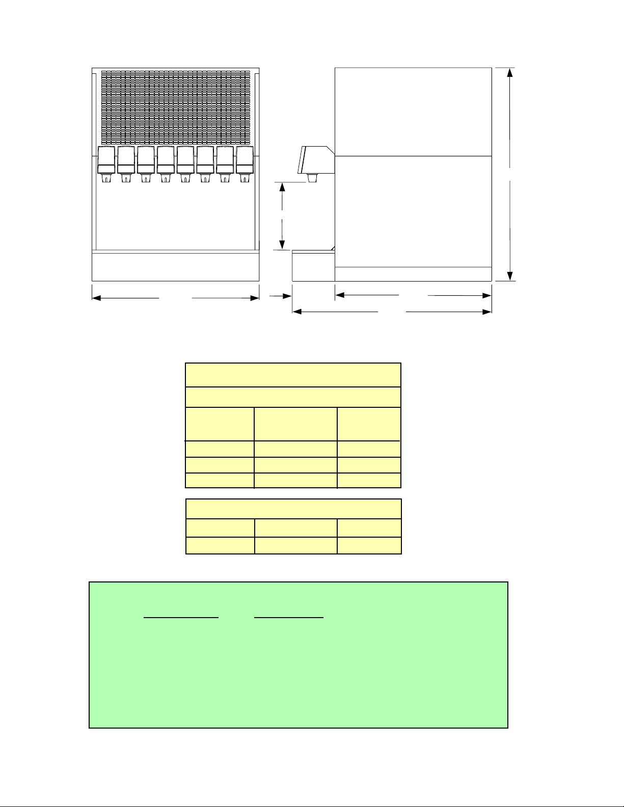
9.750
Series 8000 Performance
Draw Performance
Draws per
Minute 75
o
90
o
4-12s Indefinite 325
2-24s Indefinite 168
2-18s Indefinite 290
Initial Pull Down
75
o
90
o
105
o
2:45 3:40 5:40
i
OPTIONAL ACCESSORIES, SERIES 8000
P
ART NUMBER DESCRIPTION
82-2203 MARQUEE
06-1784 GRAPHICS, COCA-COLA, SCREENED
06-2104 GRAPHICS, COCA-COLA, THREE CUP
82-2184/01-20 MERCHANDISER KIT ASSEMBLY, USA
82-2184/01 MERCHANDISER KIT ASSEMBLY, INTERNATIONAL
30.625
24.000
6.125
22.500
28.625
Page 3

TABLE OF CONTENTS
SERIES 8000 PERFORMANCE.........................................................................................................................i
OPTIONAL ACCESSORIES, SERIES 8000 .......................................................................................................i
TABLE OF CONTENTS.....................................................................................................................................ii
SPECIFICATIONS.............................................................................................................................................iii
DISPENSER INSTALLATION HIGHLIGHTS....................................................................................................iii
1. INSTALLATION ...........................................................................................................................................1
1.1 RECEIVING .......................................................................................................................................1
1.2 UNPACKING ......................................................................................................................................1
1.3 UNPACKING INSTALLATION KITS...................................................................................................1
1.4 COUNTER SELECTION....................................................................................................................1
1.5 PROVIDING CLEARANCE................................................................................................................1
1.6 WATER REQUIREMENTS.................................................................................................................1
1.7 CARBON DIOXIDE (CO2
) REQUIREMENTS ....................................................................................2
1.8 ELECTRICAL REQUIREMENTS .......................................................................................................2
1.9 DRAIN REQUIREMENTS..................................................................................................................2
1.10 SEALING THE DISPENSER TO THE COUNTER.............................................................................2
1.11 REQUIRED TOOLS FOR INSTALLATION ........................................................................................2
1.12 MOUNTING THE DISPENSER..........................................................................................................2
1.13 CONNECTING THE DRAIN...............................................................................................................2
1.14 FILLING UNIT WITH WATER ............................................................................................................2
1.15 CONNECTING TO ELECTRICAL POWER .......................................................................................3
1.16 CONNECTING TO WATER SUPPLY.................................................................................................3
1.17 CONNECTING THE CO
2 SUPPLY ....................................................................................................3
1.18 PURGING THE CARBONATION SYSTEM .......................................................................................3
1.19 ADJUSTING WATER FLOW..............................................................................................................4
1.20 ADJUSTING WATER TO SYRUP RATIO (BRIX) ..............................................................................4
2. SCHEDULED MAINTENANCE...................................................................................................................4
2.1 DAILY .................................................................................................................................................4
2.2 WEEKLY.............................................................................................................................................4
2.3 MONTHLY..........................................................................................................................................5
2.4 EVERY SIX (6) MONTHS ..................................................................................................................5
2.5 YEARLY..............................................................................................................................................5
3. DISPENSER CLEANING AND SANITIZING..............................................................................................5
3.1 AMBIENT PROCESS.........................................................................................................................5
3.2 ALTERNATE CLEANING AND SANITIZING AGENTS ......................................................................5
4. TROUBLESHOOTING.................................................................................................................................6
4.1 WATER LEAKAGE AROUND NOZZLE.............................................................................................6
4.2 LEAKAGE BETWEEN UPPER AND LOWER VALVE BODIES.........................................................6
4.3 MISCELLANEOUS LEAKAGE...........................................................................................................6
4.4 INSUFFICIENT WATER FLOW..........................................................................................................6
4.5 INSUFFICIENT SYRUP FLOW..........................................................................................................6
4.6 ERRATIC RATIO................................................................................................................................6
4.7 NO PRODUCT DISPENSED.............................................................................................................6
4.8 WATER ONLY DISPENSED, NO SYRUP; OR SYRUP ONLY DISPENSED, NO WATER ...............7
4.9 NO WATER, JUST SYRUP. (ICE BANK GREW TO WATER INLET LINE TO
CARBONATOR TANK........................................................................................................................7
4.10 VALVE WILL NOT SHUT OFF...........................................................................................................7
4.11 SYRUP ONLY DISPENSED. NO WATER, BUT CO2 GAS DISPENSED WITH SYRUP.................7
4.12 EXCESSIVE FOAMING.....................................................................................................................7
4.13 WATER CONTINUALLY OVERFLOWS FROM WATER BATH INTO DRIP TRAY ...........................8
4.14 COMPRESSOR STARTS AND CONTINUES TO RUN UNTIL FREEZE UP AND
WILL NOT TURN OFF.......................................................................................................................8
4.15 WARM DRINKS..................................................................................................................................8
4.16 COMPRESSOR DOES NOT START (NO HUM), CONDENSER FAN MOTOR DOES NOT RUN
AND NO ICE BANK ...........................................................................................................................8
4.17 COMPRESSOR DOES NOT START (NO HUM) BUT CONDENSER FAN MOTOR
RUNS .................................................................................................................................................8
4.18 COMPRESSOR DOES NOT START BUT HUMS .............................................................................9
4.19 COMPRESSOR STARTS, BUT DOES NOT SWITCH OFF START WINDING (WILL
RUN ONLY FOR A FEW SECONDS BEFORE INTERNAL OVERLOAD SWITCHES
COMPRESSOR OFF)........................................................................................................................9
ii
Page 4

SPECIFICATIONS
DIMENSION
Width 24.000 inches (609.6 mm)
Depth 28.625 inches (727.1 mm)
Height 30.625 inches (777.9 mm)
ICE BANK WEIGHT
55.0 pounds (24.95 kg)
DISPENSER INSTALLATION HIGHLIGHTS
Listed below are six critical elements which will aid in a successful installation.
1. Fill water bath until water over flows from tank overflow tube.
NOTE
Do NOT use distilled water to fill water bath.
2. The carbonator pump motor must be disconnected from the power supply (refer to this manual Section 1.8A, Page 2) prior to connection to water supply for initial build-up of ice bank. Failure to do
so will result in automatic shut off of carbonator (see item 5 below) or damage to the pump.
3. If this dispenser is installed in an area that is susceptible to ±10% variation of the nominal line voltage,
consider installing a surge protector or similar protection device.
4. There is a five (5) minute delay which prevents the compressor and condenser fan from starting until
the delay has lapsed. If electrical current is interrupted, there is always a five (5) minute delay before
the compressor starts.
5. The unit is equipped with a protective timer [set for three (3) minutes] for the carbonator pump motor.
If the carbonator motor has timed out, it must be manually reset by either momentarily unplugging the
unit or switching the on/off switch OFF (if present). Once power is restored, the five (5) minute
compressor delay would be in effect.
6. Valve adjustment: Make sure drink temperature is below 40°F (4.4°C) before adjusting brix.
4.20 COMPRESSOR STARTS AND RUNS A SHORTTIME BUT SHUTS OFF
ON OVERLOAD.................................................................................................................................9
4.21 COMPRESSOR RUNS NORMALLY, BUT WATER LINE IS FROZEN ..............................................9
4.22 CIRCUIT BREAKER POPPING.........................................................................................................9
4.23 LOW OR NO CARBONATION...........................................................................................................9
4.24 CARBONATOR MOTOR DOES NOT RUN .....................................................................................10
4.25 REDUNDANT CONTROL LIGHT COMES ON................................................................................10
5. ILLUSTRATIONS, PARTS LISTINGS, WIRING AND PLUMBING DIAGRAMS ......................................11
5.1 WATER REGULATOR......................................................................................................................11
5.2 MERCHANDISER ASSEMBL Y.........................................................................................................11
5.3 CABINET ASSEMBLY.................................................................................................................12-13
5.4 SHROUDED ASSEMBLY, 8000 CCD.........................................................................................14-15
5.5 CARBONATOR, WATER/SYRUP LINE ASSEMBLY..................................................................16-17
5.6 CARBONATOR DECK/PUMP BRACKETASSEMBLY...............................................................18-19
5.7 REFRIGERATION DECK ASSEMBLY........................................................................................20-21
5.8 CONTROL HOUSING ASSEMBLIES .........................................................................................22-23
5.9 CONTROL HOUSING ASSEMBLIES - 115V/60HZ - REDUNDANT CONTROL ............................24
5.10 CONTROL HOUSING ASSEMBLIES - 115V/60HZ.........................................................................25
5.11 CONTROL HOUSING ASSEMBLIES - 230V/50HZ - 220V/60HZ...................................................26
5.12 WIRING DIAGRAM - 115V/60HZ, PN 06-1604 ...............................................................................27
5.13 WIRING DIAGRAM - 230V/50HZ - 220V/60HZ, PN 06-1652..........................................................28
5.14 WIRING DIAGRAM - 115V/60HZ - REDUNDANT CONTROL, PN 06-1718...................................29
5.15 PLUMBING DIAGRAM - 6 VALVE, PN 06-1716..............................................................................30
5.16 PLUMBING DIAGRAM - 8 VALVE, PN 06-1393..............................................................................31
iii
TABLE OF CONTENTS (CONTINUED)
Page 5
1. INSTALLATION
1.1 RECEIVING
Each unit is tested and thoroughly inspected before shipment. At time of shipment, the carrier
accepts the unit(s) and any claim for damages must be made with the carrier. Upon receiving unit(s)
from the delivering carrier, carefully inspect carton(s) for visible indication(s) of damage. If damage
exists, have carrier note same on bill of lading and file a claim with the carrier.
1.2 UNPACKING
A. Carefully cut steel band and remove.
B. Remove top portion of carton by lifting up.
C. Remove accessory kit and loose parts from top packaging.
D. Remove top inner carton, pad and corners.
E. Using proper lifting techniques, lift unit up by plywood shipping base, and remove lower portion
of carton.
F. Inspect unit for concealed damage. If evident, notify delivering carrier and file a claim against
same.
G. Remove plywood shipping base from unit by locating unit so that one side is off the counter top
or table, allowing access to screws on the bottom of the plywood shipping base.
NOTE
If unit is to be transported, it is advisable to leave unit secured to plywood shipping base.
H. If unit is to be installed with optional legs, assemble legs to unit by tilting unit. DO NOT LAY
UNIT ON ITS SIDE OR BACK.
1.3 UNPACKING INSTALLATION KITS
A. Inspect kits for concealed damage. If evident, notify delivering carrier and file a claim against
same.
B. Each kit contains a listing of the parts and a drawing showing the proper assembly of the parts.
1.4 COUNTER SELECTION
A. Select a location close to a properly grounded electrical outlet and water supply that meet the
requirements outlined below.
B. Counter location must be able to support a minimum of 400 pounds (181.44 kg) per unit.
1.5 PROVIDING CLEARANCE
W
ARNING
FAILURE TO MAINTAIN PROPER AIR CLEARANCE WILL CAUSE THE COMPRESSOR TO
OVERHEAT AND WILL RESULT IN PREMATURE COMPONENT FAILURE.
Condenser air is drawn in the front of the unit and discharged out the top back of the unit.
A minimum of 15 inches (381 mm) clearance must be maintained over the top of the unit.
1.6 WATER REQUIREMENTS
CAUTION
IF WATER SOURCE EXCEEDS 50 PSIG (3.52 KG/CM2), A WATER REGULATOR ASSEMBLY
MUST BE USED TO LIMIT WATER PRESSURE TO 50 PSIG (3.52 KG/CM
2
). FAILURE TO USE
REGULATOR WILL RESULT IN IMPROPER PERFORMANCE OF DISPENSER.
This dispenser incorporates a built-in cold carbonator. There are three (3) water inlets to the
dispenser. Two (2) inlets (plain water circuits) supply water to the non-carbonated drinks and one (1)
inlet (prechill circuit) supplies the carbonator pump.
A. Plain Water Circuit Requirements
Minimum flowing pressure of 40 PSIG (2.81 kg/cm
2
, 2.75 BAR).
B. Prechill Water Circuit Requirements
Minimum flowing pressure of 25 PSIG (1.76 kg/cm2, 1.72 BAR).
Maximum static pressure of 50 PSIG (3.52 kg/cm
2
, 3.44 BAR).
1
Page 6

1.7 CARBON DIOXIDE (CO2) REQUIREMENTS
Operating pressure: 75 PSIG (5.27 kg/cm2, 5.18 BAR).
1.8 ELECTRICAL REQUIREMENTS
W
ARNING
ALL ELECTRICAL CIRCUITS MUST MEET LOCAL BUILDING CODES. EACH DRINK
DISPENSER MUST BE SUPPLIED WITH A SEPARATE ELECTRICAL CIRCUIT.
The drink dispenser must have an independent (115 Volt, 60 Hz, 20 Amp; 230 Volt, 50 Hz, 10 Amp;
or, 220 Volt, 60 Hz, 10 Amp) grounded circuit, depending on dispenser configuration. The ice
dispenser should be connected per the manufacturer’s recommendations.
NOTE
The Ice Dispenser Installation Manual can be found in the ice bin, if so equipped.
1.9 DRAIN REQUIREMENTS
A drain connection should be located within three (3) feet (91.44 cm) of the dispenser.
1.10 SEALING THE DISPENSER TO THE COUNTER
When the dispenser is to be permanently mounted to the counter top, seal dispenser base to
counter top with a silicone sealant which provides a smooth, easily cleanable bond to the counter.
1.11 REQUIRED TOOLS FOR INSTALLATION
The following tools will be required for installation:
A. Screw Driver, Flat Head
B. Screw Driver, Phillips Head
C. Screw Driver, Nut Driver
D. Beverage Tubing Cutter
E. Oetiker Clamp Crimper
1.12 MOUNTING THE DISPENSER
A. The dispenser is designed to be permanently mounted and sealed to the counter, or installed on
four (4) inch legs.
NOTE
NSF listed units must be sealed to the counter or have four (4) inch legs installed.
B. When the dispenser is to be permanently mounted to the counter top, seal dispenser base to
counter top with a silicone sealant which provides a smooth, easily cleanable bond to the counter.
1.13 CONNECTING THE DRAIN
A. Remove Cup Rest. Lift Splash Plate up and pull out and down on the bottom to remove.
B. Remove the Drip Tray from the unit, and connect the drain tube to the drain fitting located on the
back. Secure Drain Tube.
C. Route the Drain Tube to a suitable drain, and replace the unit's Drip Tray.
1.14 FILLING UNIT WITH WATER
A. Remove the Bonnet from the unit.
B. Remove the Plastic Plug (located on the front of the unit's Compressor Deck) from the unit's fill
hole.
CAUTION
THE WATER BATH COMPARTMENT MUST BE FILLED WITH WATER BEFORE PLUGGING IN
THE UNIT. OTHERWISE, THE COMPRESSOR DECK AND CONDENSER FAN MAY NOT
OPERATE PROPERLY.
C. Using a funnel or tube, fill the Water Bath compartment with water until it flows out of the Overflow
Tube into the Drip Tray.
NOTE
Do NOT use distilled water to fill water bath.
D. Replace the Plastic Plug.
2
Page 7
1.15 CONNECTING TO ELECTRICAL POWER
W
ARNING
THIS APPLIANCE MUST BE EARTHED.
THIS UNIT MUST BE PROPERLY ELECTRICALLY GROUNDED TO AVOID POSSIBLE FATAL
ELECTRICAL SHOCK OR SERIOUS INJURY TO THE OPERATOR. THE POWER CORD IS
PROVIDED WITH A THREE PRONG GROUNDED PLUG. IF A THREE-HOLE GROUNDED
ELECTRICAL OUTLET IS NOT AVAILABLE, USE AN APPROVED METHOD TO GROUND THE
UNIT.
A. Disconnect the power supply to the Carbonator Motor by separating the four pin connector
located on the Electrical Control Box on the Refrigeration Deck.
CAUTION
FAILURE TO DISCONNECT THE MOTOR POWER SUPPLY WILL DAMAGE THE CARBONATOR
MOTOR AND PUMP AND VOID THE WARRANTY.
B. Check the Dispenser serial number plate for unit's correct electrical requirements. Do not plug
into wall electrical outlet unless serial number plate current shown agrees with local current
available.
C. Route the power supply cord to a grounded electrical outlet of the proper voltage and amperage
rating, and plug in the unit. This will turn on the refrigeration system and allow it to start cooling
while completing the rest of the installation. The Agitator Motor will start immediately, but the
Compressor and Fan Motor will not start until the five (5) minute delay has elapsed.
1.16 CONNECTING TO WATER SUPPLY
CAUTION
IF WATER SOURCE EXCEEDS 50 PSIG (3.52 KG/CM2), AWATER REGULATOR MUST BE USED
TO LIMIT WATER PRESSURE TO 50 PSIG (3.52 KG/CM
2
). FAILURE TO USE REGULATOR WILL
RESULT IN IMPROPER PERFORMANCE OF DISPENSER.
A. Using tubing and fittings from installation kit, connect Tubing Assembly to water source. DO
NOT CONNECT TO DISPENSER AT THIS TIME.
B. Flush water supply line thoroughly.
C. IF THE WATER SOURCE IS ABOVE 50 PSIG (3.52 KG/CM
2
), CUT TUBING ASSEMBLY AND
INSTALL WATER REGULATOR KIT.
D. Route through hole in counter and through opening behind Splash Plate and connect to
Carbonator Pump.
E. Turn on water supply and check for leaks.
F. Using Test Gauge Assembly (PN 22-0138), set Regulator at 50 PSIG (3.52 kg/cm
2
).
1.17 CONNECTING THE CO2 SUPPLY
A. Connect High Pressure CO
2 Regulator Assembly to CO2 Cylinder. Use a new CO2 Tank Washer
if Regulator does not have built-in O-Ring Seal.
B. Place CO2 Cylinder in service location under counter, etc., and secure it with a safety chain.
C. Route gas line through hole in counter and through opening behind the Dispenser Splash Plate.
CAUTION
DO NOT TURN ON THE CO2 SUPPLYAT THIS TIME
D. Connect the CO
2 supply line directly to the Carbonator CO2 Inlet Check Valve.
1.18 PURGING THE CARBONATION SYSTEM
A. The Relief Valve for the built-in Carbonator is located in front of the unit's Compressor Deck on
the right hand side. Lift the yellow lever on the top of the Relief Valve until water flows from the
holes in the Relief Valve. Then release the Relief Valve.
B. Reconnect the power supply to the Carbonator Pump.
C. Back off on the CO
2 Regulator Pressure Adjusting Screw all the way. Open the CO2 Cylinder
handle slowly. Turn the CO
2 Pressure Regulator up slowly to 75 PSIG (5.1 bar).
D. Open a Dispensing Valve until water and syrup are flowing steadily from the Valve.
3
Page 8
E. Repeat procedure “D” for each valve.
F. Check all of the unit's syrup, water, and CO
2 connections for leaks. Repair if necessary.
NOTE
To check for CO2 leaks, close the Valve on the CO2 Cylinder and observe if the pressure to the
system drops with the Cylinder Valve closed for five (5) minutes. Open the Cylinder Valve after
check.
4
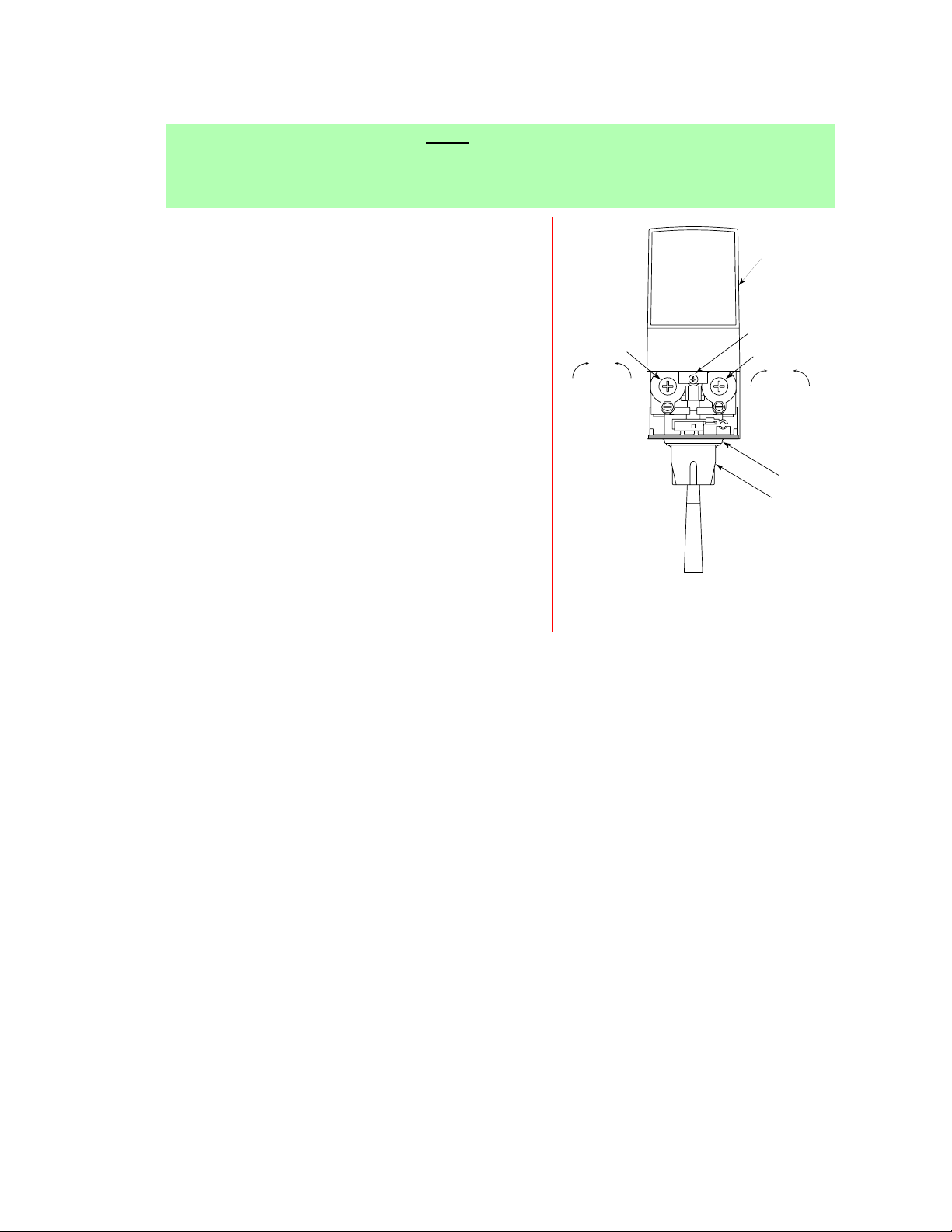
Adjusting Valve
Figure 1
I. To obtain the proper flow, use a screwdriver to adjust water flow control (see Figure 1).
J. Repeat process for each valve.
1.20 ADJUSTING WATER TO SYRUP (RATIO) BRIX
A. Hold the Lancer Brix Cup under the Syrup Separator and activate Valve. Check brix.
B. To obtain the proper brix, use screwdriver to adjust Syrup Flow Control (see Figure 1).
C. Once proper ratio is obtained, repeat to verify.
D. Remove Syrup Separator.
E. Install Diffuser and Nozzle.
F. Slide down I.D. Panel.
G. Repeat process for each Valve.
2. SCHEDULED MAINTENANCE
2.1 DAILY
A. Remove the Nozzle and Diffuser from each Valve and wash them in warm water.
B. Remove the Cup Rest and wash in warm soapy water. Rinse in warm water.
C. Pour warm soapy water into the Drip Tray and wipe with a clean cloth. Rinse in warm water.
D. With a clean cloth and warm soapy water, wipe off all of the unit’s exterior surfaces. Rinse with
warm water.
E. Replace the Cup Rest, Valve Diffusers and Valve Nozzles.
2.2 WEEKLY
A. Check the brix of each Valve, following the brixing instructions given in Section 1.20.
B. Remove the unit's Bonnet and check the level of water in the Water Bath. Replenish as
required, and replace the Bonnet.
G. Replace the unit's Bonnet, Splash Plate, and Cup Rest.
1.19 ADJUSTING WATER FLOW
A. The water flow can be adjusted between 1.25
ounces/second (37 ml/sec) and 2.50 ounces/second
(74 ml/sec) on all Dispensing Valves using the
following procedure.
B. The Refrigeration Unit should have been running for a
least one hour before you attempt to brix the Valves.
The drink temperature should be no higher than 40
o
F
(4.4oC) when the brix is set. This is best done after the
unit has made an ice bank.
C. Slide up I.D. Panel until Flow Controls are exposed.
D. Remove Nozzle by twisting counter clockwise and
pulling down.
E. Remove Diffuser by pulling down.
F. Install Lancer (yellow) Syrup Separator (PN 54-0031)
in place of Nozzle.
G. Activate Dispensing Valve to fill Separator Syrup Tube.
H. Hold a Lancer Brix Cup under the Syrup Separator and
dispense water and syrup into cup for four (4) seconds.
Divide number of ounces (ml) of water in cup by four
(4) to determine water flow rate per second.
FLOW CONTROL
WATER
DecreaseIncrease
I.D. PANEL
(Shown in
open position)
COVER SCREW
FLOW CONTROL
SYRUP
DecreaseIncrease
DIFFUSER
NOZZLE
Page 9
2.3 MONTHLY
A. Unplug the Dispenser from its power source.
B. Remove the Bonnet, and clean the dirt from the unit's Condenser using a soft brush.
C. Replace the Bonnet and plug in the unit.
2.4 EVERY SIX (6) MONTHS
A. Clean and sanitize the unit using the appropriate procedures outlined in Section 3.
2.5 YEARLY
A. Clean water bathe interior, including evaporator coils and refrigeration components.
B. Clean the entire exterior of the unit.
C. Sanitize syrup lines.
3. DISPENSER CLEANING AND SANITIZING
3.1 AMBIENT PROCESS
CAUTION
BECAUSE OF DIFFICULTY IN RINSING, DETERGENT SOLUTION SHOULD NOT BE
INTRODUCED INTO THE CARBONATOR.
A. The ambient process is the most common method for cleaning and sanitizing dispenser
equipment. The detergent should be caustic-based and the sanitizer should be a low pH (7.0)
chloride solution.
B. Disconnect syrup containers and remove product from tubing by purging with carbon dioxide.
C. Rinse the lines and fittings with clean room temperature water to remove all traces of residual
product.
D. Fill lines with a caustic-based (low-sudsing, non-perfumed, and easily rinsed) detergent solution.
The solution should be prepared in accordance with the manufacturer’s recommendations, but
should be at least 2 percent sodium hydroxide. Make sure the lines are completely filled and
allow to stand for at least 10 minutes.
E. Flush the detergent solution from the lines with clean water. Continue rinsing until testing with
phenolphthalein shows that the rinse water is free of residual detergent.
F. Fill the lines with a low pH (7.0) chlorine solution containing at least 50 PPM (50 mg/L) chlorine.
Make sure that lines are completely filled and allow to stand for 10 minutes.
G. Reconnect syrup containers and ready unit for operation.
H. Draw drinks to refill lines and flush the chlorine solution from the dispenser.
I. Taste the beverage to verify that there is no off taste.
3.2 ALTERNATE CLEANING AND SANITIZING AGENTS
A. The above approach to cleaning and sanitizing is strongly recommended. However, the Division
Quality Assurance Manager may approve other cleaning and sanitizing agents such as
chlorinated alkaline detergents.
B. However, while chlorinated alkaline detergents or compounds may be used as the cleaning
agent, they may not be used as combined cleaner/sanitizer.
W
ARNING
IODOPHORS AND QUATERNARY AMMONIUM COMPOUNDS (QUATS) ARE BROAD
CLASSES OF COMPOUNDS. SOME MEMBERS OF EACH GROUP CAN CAUSE SERIOUS
PROBLEMS WITH FOAMING, DISTORTION OR DISCOLORATION OF POLYMERIC PARTS,
POOR RINSIBILITY, AND OFF TASTE. THE RINSIBILITY AND OFF TASTE PROBLEMS HAVE
BEEN ESPECIALLY PREVALENT WITH QUATS. BECAUSE OF THE POTENTIAL PROBLEMS,
APPROVAL MUST BE GRANTED BY THE DIVISION QUALITY ASSURANCE MANAGER TO
SPECIFIC COMPOUNDS. THIS APPROVAL SHOULD BE BASED UPON TESTING IN THE
LABORATORY.
C. Iodophors may be substituted for chlorine as the sanitizing agent.
D. Quaternary ammonium compounds may be used as a combined cleaner/sanitizer, but are
generally not recommended. These compounds are not to be utilized at concentrations
exceeding 200 PPM (200 mg/L), or that concentration specified in local regulations, which ever
is lower.
5
Page 10

4. TROUBLESHOOTING
TROUBLE CAUSE REMEDY
4.1 Water leakage around A. Damaged or improperly A. If damaged, replace. If
Nozzle. installed O-Ring above improperly installed, adjust.
Diffuser.
4.2 Leakage between A. Gap between upper and A. Tighten all six (6) retaining
upper and lower valve lower valve bodies. screws.
bodies. B. Worn or damaged Paddle B. Replace Paddle Arm
Arm Assemblies. Assemblies.
4.3 Miscellaneous leakage. A. Gap between parts. A. Tighten appropriate retaining
screws.
B. Damaged or improperly B. Replace or adjust appropriate
installed O-Rings. O-Rings.
4.4 Insufficient water flow. A. Insufficient incoming supply A. Verify incoming supply water
water pressure. pressure is a minimum of 25 PSI.
B. Shutoff on Mounting Block B. Open Shutoff fully.
not fully open.
C. Foreign debris in Water Flow C. Remove Water Flow Control from
Control. upper body and clean out any
foreign material to ensure smooth
free spool movement.
D. Foreign debris in Water Pump D. Remove Water Pump Strainer and
Strainer. clean.
4.5 Insufficient syrup flow. A. Insufficient CO
2 pressure to A. Adjust CO2 pressure to 80 PSI
BIB pumps. (minimum 70 PSI) for BIB pumps.
B. Shutoff on Mounting Block B. Open Shutoff fully.
not fully open.
C. Foreign debris in Syrup Flow C. Remove Syrup Flow Control from
Control. upper body and clean out any
foreign material to ensure smooth
free spool movement.
4.6 Erratic ratio. A. Incoming water and/or syrup A. Check pressure and adjust.
supply not at minimum
flowing pressure.
B. Foreign debris in water B. Remove flow controls from upper
and/or syrup flow controls. body and clean out any foreign
material to ensure smooth free
spool movement.
4.7 No product dispensed. A. Water and syrup Shutoffs on A. Open Shutoffs fully.
Mounting Block not fully open.
B. The Key Switch on an Electric B. Turn Key Switch to ON position.
Valve is in the OFF position.
C. Cup Lever Arm or I.D. Panel C. Repair.
Actuator on Electric Valve is
not actuating the Switch.
D. Electric current not reaching D. Check electric current supplied to
Electric Valve. Valve. If current is adequate, check
Solenoid Coil and Switch, and
replace if necessary.
E. Improper or inadequate E. Remove Valve from Mounting Block
water or syrup supply. and open Shutoffs slightly and
check water and syrup supply. If no
supply, check Dispenser for
freeze-up or other problems.
F. Circuit Breaker tripped on F. Find cause of short and correct.
24 volt transformer. Then, reset transformer.
6
Page 11

4.8 Water only dispensed, A. Water or syrup Shutoff on A. Open Shutoff fully.
no syrup; or syrup only Mounting Block not fully open.
dispensed, no water. B. Improper or inadequate water B. Remove Valve from Mounting Block
or syrup supply. and open Shutoffs slightly and
check water and syrup supply. If no
supply, check Dispenser for
freeze-up or other problems.
Ensure BIB connection is engaged.
C. BIB supply too far from C. Ensure that BIB supply is within
Dispenser. six (6) feet of the dispenser.
D. CO
2 pressure too low. D. Check the CO2 pressure to the
Pump Manifold to ensure it is
between 70 and 80 PSI.
E. Stalled or inoperative BIB E. Check CO2 pressure and/or replace
Pump. Pump.
F. Kinked line. F. Remove kink or replace line.
4.9 No water, just syrup. A. Syrup in water bath. A. Melt ice bank and remove all water.
(Ice bank grew to Water Refill. Locate possible syrup leak
Inlet Line to Carbonator area and repair.
Tank.)
B. Water Cage is out of position. B. Reposition water cage.
C. Coolant leak. C. Find leak and recharge unit (if unit
is not frozen).
D. Check water supply. D. Turn on water and shut unit OFF,
then ON to reset Carbonator.
E. Carbonator timed out. E. Turn unit OFF, then ON to reset
Carbonator.
F. Ice Bank Control F. Replace Ice Bank Control.
malfunctioning.
4.10 Valve will not shut off. A. Cup Lever may be sticking or A. Correct or replace Lever.
binding.
B. Switch not actuating freely. B. Check Switch for free actuation.
C. Solenoid Armature not C. Replace defective Armature or
returning to bottom position. Spring.
4.11 Syrup only dispensed. A. Improper water flow to A. Check for water flow to
No water, but CO
2 gas Dispenser. Dispenser (see Item 4.4).
dispensed with syrup. B. Carbonator Pump Motor has B. Reset by turning the unit OFF, and
timed out. and then ON by using the ON/OFF
Switch on top of the unit, or,
unplugging unit momentarily.
C. Liquid Level Probe not C. Check connections of Liquid Level
connected properly to PCB. Probe to PCB assembly.
D. Faulty PCB Assembly. D. Replace PCB Assembly.
E. Faulty Liquid Level Probe. E. Replace Liquid Level Probe.
F. Water bath frozen. F. Thaw water bath and repair faulty
component. (See Refrigeration
Related Symptoms.)
G. Water line frozen. G. Refer to Item 4.14 listed below.
4.12 Excessive foaming. A. Incoming water or syrup A. Correct prior to dispenser.
temperature too high. Consider larger Dispenser or
Pre-cooler.
B. CO2 pressure too high. B. Adjust CO2 pressure downward,
but not less than 70 PSI.
C. Water flow rate too high. C. Readjust and reset ratio. Refer to
Section 1.19, this Manual.
D. Nozzle and Diffuser not D. Remove and reinstall properly.
properly installed.
E. Nozzle and Diffuser not clean. E. Remove and clean.
F. Air in BIB lines. F. Bleed air from BIB lines.
G. Poor quality ice. G. Check quality of ice used in drink.
H. High beverage temperature. H. Check refrigeration system.
7
TROUBLE CAUSE REMEDY
Page 12

4.13 Water continually over- A. Loose water connection(s). A. Tighten water connections.
flows from water bath
into Drip Tray. B. Flare Seal Washer leaks. B. Replace Flare Seal Washer.
C. Faulty Water Coil. C. Replace Water Coil.
4.14 Compressor starts and A. Ice Bank Control A. Replace Ice Bank Control.
continues to run until malfunctioning.
freeze up and will not B. Ice Bank Probe positioned B. Check positioning of Ice Bank
turn off. improperly. Probe, and reset (if needed).
NOTE:
First check to ensure that the three (3) minute Carbonator Timer has not timed out. Turn unit OFF,
and then ON. If the pump shuts off in less than 30 seconds, the Dispenser is not frozen.
4.15 Warm drinks. A. Restricted airflow. A. Check clearances around sides,
top, and inlet of unit. Remove
objects blocking airflow through
grill.
B. Dispenser connected to hot B. Switch to cold water supply.
water supply.
C. Refrigeration system not C. Refer to Items 5.15 through 5.19.
running.
D. Refrigerant leak. D. Repair and recharge.
E. Condenser Fan Motor not E. Replace Condenser Fan Motor.
working.
F. Dirty Condenser. F. Clean Condenser.
G. Dispenser capacity exceeded. G. Add Pre-Cooler, or replace with
larger dispenser.
4.16 Compressor does not A. There is a five (5) minute A. Allow for five (5) minute delay to
start (no hum), Con- Compressor and Condenser lapse.
denser Fan Motor does Fan delay.
not run and no ice bank. B. Ice Bank Probe not B. Fill Water Reservoir until water
completely submerged. flows from Overflow Tube.
C. Circuit Breaker or Fuse C. Reset Breaker or replace Fuse. If
tripped. problem persists:
1. Determine reason and correct.
2. Electrical circuit overloaded;
switch to another circuit.
D. Inadequate voltage. D. Measure voltage across common
and run terminal on Compressor.
Voltage must not drop below 90%
of rated voltage.
E. Ice Bank Control E. Replace Ice Bank Control.
malfunctioning.
F. Incorrect wiring. F. Refer to Wiring Diagram and
correct.
G. Circuit Breaker tripped on G. Find cause of short and correct.
24 volt transformer. Then reset transformer.
4.17 Compressor does not A. Compressor Relay or A. Replace Compressor Relay or
start (no hum), but Overload malfunctioning. Overload.
Condenser Fan Motor B. Inadequate voltage. B. Measure voltage across common
runs. and run Terminal on Compressor.
Voltage must not drop below 90%
of rated voltage.
C. Incorrect wiring. C. Refer to Wiring Diagram and
correct.
D. Compressor malfunctioning. D. Replace Compressor.
8
TROUBLE CAUSE REMEDY
Page 13

4.18 Compressor does not A. Inadequate voltage. A. Measure voltage across common
start, but hums. and run Terminal on Compressor.
Voltage must not drop below 90%
of rated voltage.
B. Incorrect wiring. B. Refer to Wiring Diagram and
correct.
C. Starting Relay malfunctioning. C. Replace Starting Relay. Be sure to
use correct relay. Failure to use
correct relay will cause Compressor
failure.
D. Compressor malfunctioning. D. Replace Compressor or Deck.
4.19 Compressor starts, but A. Inadequate voltage. A. Measure voltage across common
does not switch off start and run Terminal on Compressor.
winding (will run for only B. Incorrect wiring. B. Refer to Wiring Diagram and
a few seconds before correct.
internal overload C. Starting Relay malfunctioning. C. Replace Starting Relay. Be sure to
switches Compressor use correct relay. Failure to use
off). correct relay will cause Compressor
failure.
4.20 Compressor starts A. Dirty Condenser. A. Clean the Condenser.
and runs a short time B. Insufficient or blocked air flow. B. Remove all obstructions and allow
but shuts off on for minimum clearances of eight (8)
overload. inches (203 mm) over top of unit.
C. Inadequate voltage. C. Measure voltage across common
and run Terminal on Compressor.
Voltage must not drop below 90%
of rated voltage.
D. Incorrect wiring. D. Refer to Wiring Diagram and
correct.
E. Defective Condenser Fan E. Replace Condenser Fan Motor.
Motor.
F. Refrigerant coolant leak. F. Repair and recharge.
G. Compressor malfunctioning. G. Replace Compressor.
4.21 Compressor runs A. Low water level in Water Bath. A. Add water to Water Bath until water
normally, but water line B. Syrup in Water Bath. runs out of overflow into Drip Tray.
is frozen. B. Drain water from Water Bath and
refill with clean water.
C. Water Cage is out of position. C. Reposition Water Cage.
D. Low coolant charge/slow D. Find and repair leak. Recharge
coolant leak. system.
4.22 Circuit Breaker popping. A. Valve Wire Harness shorted A. Detect short by disconnecting
to itself or to Faucet Plate. input faston to keylock and single
pin connector. Restore power. If
Breaker doesn't pop, then Valve
Wire Harness is shorted; if OK,
reconnect.
B. Secondary Wire Harness is B. If Breaker does not pop, locate
bad. short in Secondary Wire Harness
between transformer, PCB and
Valve Wire Harness.
C. Transformer failure. C. Detect short by disconnecting both
Transformer fastons and restore
power. If Breaker does pop,
replace Transformer.
4.23 Low or no carbonation. A. Low or no CO2. A. Check CO2 supply. Adjust CO2
pressure to 70 PSI.
B. Excessive water pressure. B. Water Regulator should be set at
50 PSI.
C. Worn or defective Carbonator C. Replace Carbonator Pump.
Pump.
9
TROUBLE CAUSE REMEDY
Page 14

4.24 Carbonator Motor does A. Incorrect Wiring. A. Refer to Wiring Diagram and
not run. correct.
B. Bad Carbonator Capacitor. B. Replace Carbonator Capacitor.
C. Blown Fuse on PCB. C. Repair cause of blown Fuse and
replace defective or blown Fuse.
D. Relay failure D. Replace Relay/PCB.
E. Transformer failure. E. Replace Transformer.
4.25 Redundant Control A. Probe failure. A. Replace Probe.
Light comes on. B. PCB/Relay failure. B. Replace PCB/Relay.
C. Probe Springs contacting C. Replace Probe.
each other.
D. Incorrect Probe Wiring. D. Refer to Wiring Diagram and
correct or replace as required.
NOTES
10
TROUBLE CAUSE REMEDY
NOTES
Page 15

1
ITEM PART NO. DESCRIPTION
- 18-0302 Regulator Water Assy
1 07-0438 Clamp, Oetiker
2 08-0311 Hose
3 18-0252 Regulator
4 01-0446 Stem, Hose, 9/16 inch, Brass
5 15-0087 Sealant, Perma-Lok, Pure
6 07-0481/01 Bracket, Regulator
7 04-0504 Screw, 8 - 18 x 0.375 AB
8 01-1429 Nut, 7/8 - 18 UNS
5. ILLUSTRATIONS, PARTS LISTINGS, WIRING AND PLUMBING DIAGRAMS
5.1 WATER REGULATOR
5.2 MERCHANDISER ASSEMBLY
ITEM PART NO. DESCRIPTION
- 82-2184/01-20 Merchandiser Kit Assy, USA
- 82-2184/01 Merchandiser Kit Assy,
International
1 51-5544 Plate Assy, Front Merchandiser
2 10-0229 Stand Off
3 04-0069 Screw, 10 - 24 x 0.500, PH,
Machine
4 06-1966 Decal, Merchandiser, USA, 8000
- 06-1965 Decal, Merchandiser,
International, 8000
R
T
RADEMARKS
1
2
3
4
11
6
3
2
1
5
4
5
8
4
7
Page 16

9
5.3 CABINET ASSEMBLY
12
33
27
19
36
22
37
8
16
10
11
35
9
29
21
4
38
15
12 40
31
28
30
6
24
32
7
6
20
25
32
5
1
26
2
3
18
34
23
6
14
13
17
3
Page 17

5.3 CABINET ASSEMBLY (CONTINUED)
ITEM PART NO. DESCRIPTION
- 82-2089-01 Cabinet Assy, Self-Serve, 8000
- 82-2089-06 Cabinet Assy, MDS, 8000
- 82-2089 Cabinet Assy, 8000
1 30-7039 Wrapper, Tank, 8000
2 12-0097 Key Switch
3 30-7087 Cover, Two (2) Inch Base
4 04-0068 Screw, 10 - 24 X 0.375 FH, Machine
5 42-0101 Tank Assy, Foamed, 8000
6 04-0504 Screw, 8 - 18 X 0.375 AB
7 30-7042 Front Plate, 8000
8 REF Faucet Plate Assy
- 51-5515 Faucet Plate Assy, 6 Valve, 8000
- 51-5579 Faucet Plate Assy, 8 Valve, 8000
9 REF Harness Assy
- 52-2032 Harness Assy, 6 Valve, 8000
- 52-0893 Harness Assy, 8 Valve, 8000
10 13-0005 Bushing
11 11-0015 Socket, Housing
12 05-1508 Drip Tray Top, 8000
13 51-5510 Weld Assy, Drip Tray, 8000
14 04-0407 Screw, 6 - 19 X 0.500, PHD
15 REF Splash Plate
- 30-7080 Splash Plate, for Drip Tray, 8000
- 30-7028 Splash Plate, No Drip Tray, 8000
16 REF Cup Rest
- 23-1209 Cup Rest, 8000
- 23-1219 Cup Rest, Sure-Fill, 8000
17 51-5529 Frame Assy, Base
18 06-0075-01 Nameplate, Serial Number
19 23-1208 Bonnet Assy, 8000 (Graphics Ordered
by Country)
- 23-1092 Bonnet Assy, Self-Serve, 8000
- 23-1235 Bonnet Assy, Front Access, 8000
- 23-1223 Bonnet Assy, MDS
20 03-0062 Clip, Retaining
21 04-0074 Nut, Clip
22 50-0307 Insulation, Back, 8000
23 04-0072 Rivet
24 04-0077 Screw, 4 - 20 X 0.250 AB
25 04-0545 Screw, 8 - 16 X 0.780 Plastite
26 06-0881 Label, Key Switch
27 06-0632 Label CAUTION, Bonnet
28 06-0851 Label, Overflow
29 50-0308 Insulation, Front, 8000
30 08-0004 Drain Tube, 8000
31 03-0302 Clip, Retaining, Drain Tube, 8000
32 50-0306 Insulation, Sides, 8000
33 05-0786 Plug, Bonnet
34 REF Name Plate
- 06-0075-86 Name Plate, 8006 Model
- 06-0075-88 Name Plate, 8008 Model
35 82-2121 Merchandiser Plate Assy, 8000
13
ITEM P
ART NO. DESCRIPTION
36 10-0229 Stand Off
37 04-0069 Screw
38 30-5314 Shim Plate
39 07-0405 Plug, Key Lock
40 05-1054 Fitting, Insert X IPS, 3/4 inch
NOTE: For the No Drip Tray Configuration, Items
37 - 40 in Figure 5.4 replace Items 12 - 16
and Item 40 in Figure 5.3.
Page 18

14
5.4 SHROUDED ASSEMBLY, 8000 CCD
5
6
7
8
12
13
14
15
1
4
2
3
9
THIS AREA SLIGHTLY
ENLARGED TO SHOW
MORE DETAIL
39
38
16
32
40
31
37
30
27
33
25
22
36
29
10
11
28
10
34
21
26
17
18
20
23
24
19
35
Page 19

ITEM PART NO. DESCRIPTION
1 23-1070 Bonnet, Insert
- 52-1858 Reflector Assy (Includes Items 2
through 9)
2 52-1754/01 PCB Board
3 12-0225 Lampholder, Bi-Pin
4 30-5637 BRKT, Marquee, Reflector, Support
5 30-7313 BRKT, Reflector
6 04-1046 Receiver, Stud
7 04-0336 Rivet, SS, 42BS
8 12-0254 Lamp, Fluorescent
9 04-0613 Screw, 6 - 32 x 0.250
- 82-1964 Marquee Assy (Includes Items 10
through 16)
10 27-0051 Lens, Marquee
11 06-1379 Graphics, Marquee, Thirst On Ice
12 04-1044 Stud, Ball
13 04-1045 Spacer, Nylon, 0.500 x 0.250
14 05-1562 Marquee
15 04-0780 Screw, 6 - 32 x 0.750
16 05-1566 Retainer, Lens, Marquee
- 82-1977 Shroud Assy, 8 Valve (Includes Items
17 through 33)
- 82-1965 Shroud Assy, 6 Valve (Includes Items
17 through 33)
17 04-0406 Screw, 8 - 32 x 0.375
18 30-7145 BRKT, Shroud Slide
19 12-0199 Switch, Water, Push Button
20 10-0501 Bearing, Slide
21 05-1337 Slide, Shroud, 8 Valve
- 05-1561 Slide, Shroud, 6 Valve
22 52-2071 Wire Harness, Switch
23 10-0502 Knob, Slide
24 52-2074 Wire Harness, Soda Only
25 04-0269 Screw, 8 - 16 x 0.375
26 05-1336 Shroud, 8 Valve, Self Serve
- 05-1560 Shroud, 6 Valve, Self Serve
27 04-1032 Screw, 8 - 32 x 0.375
28 06-1681 Decal, Soda Water Only
29 12-0216 Boot, Splash Proof
30 02-0502 Gasket, Bottle Cap Button
31 05-1214/01 Holder, Switch, Ribbed
32 12-0259 Switch, Bottle Cap
33 05-1213 Housing, Bottle Cap, MDS
34 51-5397 BRKT Assy, Left Valve Cover Holder
35 51-5398 BRKT Assy, Right Valve Cover Holder
36 30-6745 BRKT, Valve Cover, 8 Valve
- 30-7301 BRKT, Valve Cover, 6 Valve
37 23-1156 Splash Plate, without Drip Tray
38 REF Frame Assy, Cup Rest
- 51-5491 Frame Assy, Cup Rest, Self-Serve, 8
Valve
- 51-5492 Frame Assy, Cup Rest, Self-Serve, 6
Valve
39 REF Cup Rest, Target
- 23-1075 Cup Rest, Target, 8 Valve
- 51-5492 Cup Rest, Target, 6 Valve
40 04-0148 Screw
NOTE: For the No Drip Tray Configuration, Items
37 - 40 in Figure 5.4 replace Items 12 - 16
and Item 40 in Figure 5.3.
5.4 SHROUDED ASSEMBLY, 8000 CCD (CONTINUED)
15
ITEM PART NO. DESCRIPTION
Page 20

5.5 CARBONATOR, WATER/SYRUP LINE ASSEMBLY
16
27
27
27
25
27
25
22
16
15
14
24
13
10
12
24
20
9
11
3
17
4
5
7
6
8
23
26
20
5
10
7
6
28
8
26
31
30
2
1
37
32 (REF)
36
29
17
30
31
36
17
8
7
5
8
7
5
6
20
18
19
6
20
21
26
36
FIGAL/REMOTE
CONFIGURATION
36
32 (REF)
BAG-IN-BOX
CONFIGURATION
32 (REF)
32
(REF)
33
35
34
32 (REF)
36
35
32 (REF)
36
Page 21

ITEM PART NO. DESCRIPTION
- 82-2092 Carbonator Assy, 230V/50Hz,
With Pumps
- 82-2102 Carbonator Assy, 115V/60Hz,
Without Pumps
- 82-2110 Carbonator Assy, 230V/50Hz,
Without Pumps
- 82-2116 Carbonator Assy, 115V/60Hz,
With Pumps
1 REF Tank Assy, Carbonator
- 23-1212 Tank Assy, Carbonator, 60 Cycle
- 23-1215 Tank Assy, Carbonator, 50 Cycle
2 02-0096 Washer
3 52-2043 Probe Assy
- 17-0468 Fitting Assy, CO
2 IN (For Use
With Pumps)
- 17-0469 Fitting Assy, CO2 IN (For Use
Without Pumps)
4 01-1311 Fitting Sub-Assy, CO
2
5 02-0003 O-Ring
6 01-0689 Sleeve
7 01-0674 Ball
8 02-0025 O-Ring
9 01-1334 Body, Check Valve, Gas
10 01-0669 Body, Check Valve, Gas
- 54-0066 Relief Valve Assy
11 02-0023 Seat
12 05-0536 Stem
13 03-0024/01 Spring
14 05-0537 Body, Relief Valve
15 05-0525 Lever
16 81-0196 Pin
17 05-0011 Flare Seal Washer, Small
- 17-0485 Valve Assy, Double Check
- 17-1001 Valve Assy, Check, Carmun
18 01-1466 Fitting, Check Valve
19 01-0673 Body
20 03-0021 Spring
21 01-0670 Body
22 48-1596 Tube Assy, Plain Water Coils, 8000
23 48-1617 Tube Assy, Soda Coils, 8000
24 30-7202 Water Coils Separators, 8000
25 30-7073 Brace, Water Coils, 8000
26 01-1697 Spacer, 10 - 24, TRD
27 04-0222/01 Screw, 10 - 24 X 1.50 RHD, SL,
MS, SS
28 REF Manifold Assy
- 48-1598 Rechill Manifold Assy, 6 Valve
29 48-0492/01 Adapter, CO2 Water Out
30 01-0204 Cap
31 05-0017 Flare Seal Washer, Large
32 REF Syrup Tube Assemblies
- Syrup Tubes - 6 Valve Unit, No Pumps,
1/4 Barb Inlet
- 48-1508 Tube Assy, Syrup #1
- 48-1509 Tube Assy, Syrup #2
- 48-1510 Tube Assy, Syrup #3
- 48-1511 Tube Assy, Syrup #4
- 48-1512 Tube Assy, Syrup #5
- 48-1513 Tube Assy, Syrup #6
- Syrup Tubes - 6 Valve Unit, No Pumps,
3/8 Barb Inlet
- 48-1411 Tube Assy, Syrup #1
- 48-1412 Tube Assy, Syrup #2
- 48-1413 Tube Assy, Syrup #3
- 48-1414 Tube Assy, Syrup #4
- 48-1415 Tube Assy, Syrup #5
- 48-1416 Tube Assy, Syrup #6
- Syrup Tubes - 6 Valve Unit, With Pumps
- 48-1520 Tube Assy, Syrup #1
- 48-1521 Tube Assy, Syrup #2
- 48-1522 Tube Assy, Syrup #3
- 48-1523 Tube Assy, Syrup #4
- 48-1524 Tube Assy, Syrup #5
- 48-1525 Tube Assy, Syrup #6
- Syrup Tubes - 8 Valve Unit, No Pumps,
1/4 Barb Inlet
- 48-1640 Tube Assy, Syrup #1
- 48-1641 Tube Assy, Syrup #2
- 48-1642 Tube Assy, Syrup #3
- 48-1643 Tube Assy, Syrup #4
- 48-1644 Tube Assy, Syrup #5
- 48-1645 Tube Assy, Syrup #6
- 48-1646 Tube Assy, Syrup #7
- 48-1647 Tube Assy, Syrup #8
- Syrup Tubes - 8 Valve Unit, No Pumps,
3/8 Barb Inlet
- 48-1192 Tube Assy, Syrup #1
- 48-1193 Tube Assy, Syrup #2
- 48-1194 Tube Assy, Syrup #3
- 48-1195 Tube Assy, Syrup #4
- 48-1196 Tube Assy, Syrup #5
- 48-1197 Tube Assy, Syrup #6
- 48-1198 Tube Assy, Syrup #7
- 48-1199 Tube Assy, Syrup #8
- Syrup Tubes - 8 Valve Unit, With Pumps
- 48-1175 Tube Assy, Syrup #1
- 48-1176 Tube Assy, Syrup #2
- 48-1177 Tube Assy, Syrup #3
- 48-1178 Tube Assy, Syrup #4
- 48-1179 Tube Assy, Syrup #5
- 48-1180 Tube Assy, Syrup #6
- 48-1181 Tube Assy, Syrup #7
- 48-1182 Tube Assy, Syrup #8
33 08-0029 Tube, Flexible
34 REF Adapter Assy
- 01-1483 Adapter Assy, Elbow
35 07-0409 Clamp, Oetiker
36 02-0005 O-Ring
37 17-1004 Valve Assy , Check
5.5 CARBONATOR, WATER/SYRUP LINE ASSEMBLY (CONTINUED)
ITEM PART NO. DESCRIPTION
17
Page 22

5.6 CARBONATOR DECK/PUMP BRACKET ASSEMBLY
R
18
TO
36
37
31
29
FROM
2
CO SOURCE
27
35
32
26
34
28
CARBONATO
28
33
32
34
41
30
34
25
38
TO
LINE
SYRUP
9
9
19
19
39
31
40
7
TO SYRUP
11
14
9
LINE
5
FILL
HOLE
22
16
ICE BANK
12
4
1
17
3
2
-IMPORTANT-
REMOVE ICE BANK PROBE BEFORE
PROBE
REMOVING COMPRESSOR DECK
1
13
18
10
6
15
8
23
20
21
17
24
9
12
16
PRIMARY
ICE BANK
PROBE
REDUNDANT
ICE BANK
PROBE
-IMPORTANT-
REMOVE ICE BANK PROBE BEFORE
REMOVING COMPRESSOR DECK
2
42
23
Page 23

ITEM PART NO. DESCRIPTION
- 82-2094 Deck Assy, Carbonator, 115V/60Hz,
8000
- 82-2104 Deck Assy, Carbonator, 230V/50Hz,
8000
- 82-2147 Deck Assy, Carbonator, 115V/60Hz,
Redundant Control
- 82-2381 Deck Assy, Carbonator, 230V/50Hz,
Redundant Control
1 REF Plate, Carbonator Deck
- 51-5524 Carbonator Deck Assy, PEM, 8000
- 51-5552 Carbonator Deck Assy, PEM,
Redundant Control
2 REF Insulation, Carbonator Deck
- 50-0305 Insulation, Carbonator Deck, 8000
- 50-0317 Insulation, Carbonator Deck,
Redundant Control
3 05-0436 Sleeve, Probe
4 05-0502 Sleeve, CO
2 IN
5 04-1004 Cap Plug, Two (2) Inch Fill Hole
6 REF Pump, BR, 100GPH
- 86-0001 Pump, 100GPH
- 86-0085 Pump, 100GPH, Fluid-O-Tech
7 REF Carbonator Motor
- 91-0063 Carbonator Motor, 115V/60Hz
- 91-0065 Carbonator Motor, 220V/50-60Hz
8 50-0309 Insulation, Carbonator Bracket
9 04-0061 Screw, 8 - 18 X 0.500, PHD
10 07-0017 Clamp with Screw
11 01-0987 Elbow, 90, 3/8 MF X 3/8 MP
12 04-0576 Washer, Lock, Internal Tooth
13 REF Label, Carbonator Motor
- 06-0431 Label, 115V/60Hz, 1/4HP
- 06-0461 Label, 220V/50-60Hz
14 06-1648 Label, Cap Plug
15 23-1211 Assy, Pump Outlet, 8000
16 04-0110 Nut, 8 - 32, ST, BT
17 06-0877 Label, Ground
18 30-7069 Bracket, Carbonator Motor
19 04-1013 Bolt, Carriage, 1/4 - 20 X 0.750
20 04-0032 Nut, Lock, 1/4 - 20, ST, BT
21 04-0033 Washer, Flat, 1/4 X 0.065, TX
22 06-1649 Label, Probe
23 06-1605 Label, Remove Probe
24 06-1683 Label, Redundant Probe
- 82-2093 Pump Bracket Assy, 6 Pump
- 82-2201 Pump Bracket Assy, 8 Pump
25 51-5512 Bracket Assy, Mini-Pump
26 02-0005 O-Ring
27 04-0359 Screw
28 04-0275 Screw, Half Moon
29 07-0441 Clamp, Oetiker
30 54-0093 Manifold Assy
31 54-0092 Manifold Assy
32 54-0091 Manifold Assy
33 05-0604 Plug, CO
2 Manifold
34 13-0005 Strain Relief, Bushing
35 08-0271 Tube, CO2
36 08-0268 Tube, CO2
37 08-0269 Tube, CO
2
38 49-0221 Tube Assy, 12 Inch
39 49-0271 Tube Assy, 18 Inch
40 48-1556 Tube Assy, Carbonator Pump
41 82-0251 Mini Pump
42 06-1682 Label, Primary Probe
5.6 CARBONATOR DECK/PUMP BRACKET ASSEMBLY (CONTINUED)
ITEM PART NO. DESCRIPTION
19
Page 24

5.7 REFRIGERATION DECK ASSEMBLY
LOAD
LINE
20
37
33 36
62
22
26
1
23
9
8
64
31
25
29
30
28
27
20
34
9
24
60
53
35
5
2
9
8
54
55
15
14
59
6
3
57
4
11
59
6
32
41
13
47
13
48
18
49
51
13
50
19
61
17
7
58
7
12
21
63
42
10
56
16
13
52
31
43
39
45
38
46
40
46
44
45
Page 25

ITEM PART NO. DESCRIPTION
- 82-2091 Deck Assy, Refrigeration, 115V/60Hz,
134A
- 82-2146 Deck Assy, Refrigeration, 115V/60Hz,
134A, Redundant Control
- 82-2146-06 Deck Assy, Refrigeration, 115V/60Hz,
134A, Redundant, MDS
- 82-2130 Deck Assy, Refrigeration, 115V/60Hz,
134A, Export
- 82-2195 Deck Assy, Refrigeration, 220V/60Hz,
134A
- 82-2101 Deck Assy, Refrigeration, 230V/50Hz,
134A
- 82-2382 Deck Assy, Refrigeration, 230V/50Hz,
134A, Redundant Control
- 82-2382-06 Deck Assy, Refrigeration, 230V/50Hz,
134A, Redundant Control, MDS
- 82-2384 Deck Assy, Refrigeration, 220V/60Hz,
134A, Redundant Control
- 82-2384-06 Deck Assy, Refrigeration, 220V/60Hz,
134A, Redundant Control, MDS
1 51-5523 Deck/Pem Assy, Compressor
- 51-5551 Deck/Pem Assy, Compressor, Redundant
Control
2 50-0304 Insulation, Compressor Deck
3 04-0063 Washer, Flat
4 89-0014 Cover, Hole
5 REF Evaporator Coil Assy
- 82-2090 Evaporator Coil Assy, 8000
- 82-2148 Evaporator Coil Assy, Redundant Control
6 52-2053 Probe Assy, EIBC
- 52-2088 Probe Assy, Redundant EIBC
7 04-0470 Screw, 6 - 19 X 0.438
8 07-0268 Handle, 2000X Compressor Deck
9 04-0260 Screw, 10 - 16 X 0.625, OHD, PH, AB,
SS, ZP
10 REF Control Housing Assy
- 52-2055 Control Housing Assy, with ON/OFF
Switch, 115V/60Hz
- 52-2090 Control Housing Assy, 115V/60Hz,
Redundant Control
- 52-2090-06 Control Housing Assy, 115V/60Hz,
Redundant, MDS
- 52-2068 Control Housing Assy, 115V/60Hz, Without
Kill Switch
- 52-2059 Control Housing Assy, 230V/50Hz
- 52-2104 Control Housing Assy, 220V/60Hz
11 30-7079 Cover, Control Housing
- 30-7166 Cover, Control Housing, Redundant
Control
12 02-0032 Washer
13 04-0504 Screw, 8 - 18 X 0.375
14 51-5519 Holder Assy, Probe
15 51-5548 Bracket, Holder Assy
16 52-2048 Lead Assy, Ground
17 REF Transformer
- 25-0047 Transformer, 75VA, 24V, 115V/50-60Hz,
Reset Breaker
- 25-0048 Transformer, 75VA, 24V, 220V/50-60Hz,
Reset Breaker
18 REF Motor Assy
- 52-2034 Motor Assy, Agitator, 25W, 115V/60Hz, 8
Inch Vented
- 52-2060 Motor Assy, Agitator , 230V/50Hz, 18.3
Watts, 8 Inch
19 30-5113/01 Bracket, Agitator
20 05-0424/01 Propeller, 2.625 Diameter, 35
o
Pitch
21 05-0502 Propeller, 2.250 Diameter, 37
o
Pitch
22 02-0040 Seal, Extrusion
23 04-0032 Nut, NYLOK, 1/4 - 20
24 04-0033 Washer, Flat (0.281 ID)
25 REF Compressor
- 83-0104 Compressor, 3/4 HP, 134A, 115V/60Hz
- 83-0105 Compressor, 3/4 HP, 134A,. 230V/50Hz
- 83-0106 Compressor, 3/4 HP, 134A, 220V/60Hz
26 02-0114 Grommet, Compressor
27 04-0537 Washer, Flat (0.467 ID)
28 03-0150 Retainer, Clip
29 13-0006 Cover, Terminal
30 03-0301 Bale Strap
31 47-0344 Tube, Process
32 47-2047 Tube, Compressor (HI Side)
33 47-2065 Tube, Suction Line
34 51-5400 Accumulator, Vertical
35 50-0105 Boot
36 50-0310 Insulation, Tube, 35 Inch
37 50-0311 Insulation, Tube, 15 Inch
38 23-1210 Condenser
39 50-0312 Insulation, Baffle, Right
40 50-0313 Insulation, Baffle, Left
41 50-0314 Insulation, Baffle, Top
42 50-0315 Insulation, Baffle, Control Box
43 30-7184 Bracket, Baffle, Right
44 30-7185 Bracket, Baffle, Left
45 30-7186 Plate, Retainer
46 04-0518 Rivet, 0.1250 X 0.328
47 51-5577 Bracket/Shroud Assy, Fan
48 REF Motor, Fan
- 91-0017 Motor, Fan, 35W, 115V/60Hz
- 91-0019 Motor, Fan, 35W, 230V/60Hz
49 07-0553 Fan Blade, 11 Inch, 4 Petal, 28 Degree
50 04-0060 Nut, Flat
51 02-0413 Silencer
52 23-0999 Dryer Cap Assy
53 04-0110 Nut, 8 - 32
54 04-0576 Washer, Internal Tooth
55 06-0877 Label, Ground
56 06-1719 Label, Connector Locations, Redundant
Control
- 06-1609 Label, Connector Locations, Electric Box
57 51-5520 Bracket Assy, Slider
58 51-5547 Bracket Assy, Slider,
Redundant Control
59 13-0089 Relief, Strain 90 Degree
60 30-7173 Bracket, Transformer
61 26-0377 Capacitor, Carbonator Motor (230V/50Hz
ONLY)
62 06-0080-01 Label, Name Plate
63 04-0059 Screw, 8 - 36 X 0.375, PHD
64 01-1713 Fitting, Reducer, EL, 1/2 X 5/16
65 REF Overload
- 12-0227 Overload, Thermal, 3/4 HP, Compressor,
115V/60Hz
- 12-0045 Overload, Thermal, 3/4 HP Compressor,
230V/60Hz
66 95-0177 Refrigerant, R134A
67 30-7071 Bracket, Filter, Left
68 30-7172 Bracket, Filter, Right
69 23-1218 Air Filter Assy, 8000
- 23-1222 Air Filter Assy, MDS
70 52-1213 Harness Assy, Transformer, Second
5.7 REFRIGERATION DECK ASSEMBLY (CONTINUED)
ITEM PART NO. DESCRIPTION
21
Page 26

5.8 CONTROL HOUSING ASSEMBLIES
IBC
IBC
J3
RLY2
F1
C1
J
BR1
J2
16
J5
RLY1
TIMED
TIME
NO
1
C5
C3
C4
J4
3
5
4
21
6
NOTE: See Sections 5.9, 5.10, and 5.11 for a continuation of this illustration.
22
43
28
28
19
DETAIL A
51
51
53
52
15
12
19
41
28
1
14
42
40
15
15
26
22
29
16
23
38
SEE
DETAIL A
29
25
34
32
33
27
36
13
11
39
22
29
21
48
20
17
42
48
50
14
12
48
29
30
28
31
37
21
24
18
30
Page 27

ITEM
PART NO. DESCRIPTION
- 52-2059 Control Housing, Without ON/OFF,
230V/50Hz
- 52-2055 Control Housing, With ON/OFF,
115/V60Hz
- 52-2068 Control Housing, Without ON/OFF,
115V/60Hz
- 52-2090 Control Housing, Redundant Control,
115V/60Hz
- 52-2090-06 Control Housing, MDS, 115V/60Hz
- 52-2104 Control Housing, 220V/60Hz
1 52-2037 Harness Assy, Recirc A/C Outlet
2 52-2038 Lead Assy, Hot, Power Supply
3 52-2039 Lead Assy, Common Inlet
4 52-2040 Lead Assy, Ground Inlet
5 52-2041 Lead Assy, Hot, PCB, Transformer
6 52-2042 Lead Assy, Common, PCB
7 52-2044 Lead Assy, Carbonator, Terminal PCB
8 52-2045 Lead Assy, Compressor, Terminal
PCB
9 52-2046 Lead Assy, Compressor, PCB Relay
10 52-2047 Lead Assy, Common Relay
11 04-1024 Retainer, Nylon
12 52-2050 Harness Assy, Carbonator Probe
13 52-2051 Cable Assy, Compressor Relay
14 52-2052 Harness Assy, EIBC Probe
15 04-0504 Screw, 8 - 18 X 0.375
16 30-7166 Cover, Control Box, RC
- 30-7079 Cover, Control Box
17 11-0369 Plug, Male, Schurter
18 12-0190 Block, Terminal
19 52-0908 Harness Assy, Carbonator
20 04-0072 Rivet, 0.125 Diameter X 0.312
21 13-0059 Bushing, 2850, Convert
22 51-5555 Control Box Hinge Assy, RC
- 51-5528 Control Box Hinge Assy
23 13-0088 Relief, Strain, 14/3 SJT
24 52-1423 PC Board Assy, Series II
25 04-1015 Stud, Wing Head
26 04-1016 Receptacle, Clip-On
27 04-1017 Spring, SS, Ejector
28 04-0477 Screw, 8-32 X .375, PHD
29 13-0047 Stand-Off, 0.250
30 11-0186 Jumper, Terminal, 40 Circuit
31 12-0233 Capacitor, Start, 115V/60Hz
- 12-0246 Capacitor, Start, 220V/60Hz
- 12-0235 Capacitor, Start, 230V/50Hz
32 12-0231 Capacitor, Run, 115V/60Hz
- 03-0303 Clip, Capacitor, Retaining (For 220V
and 230V 50/60Hz Only)
33 12-0232 Relay, Compressor, 115V/60v
- 12-0247 Relay, Compressor, 220V/60Hz
- 30-7034 Bracket, 220V Compressor, Relay
(For 220V Use Only)
- 12-0236 Relay, Compressor, 230V/50Hz
34 30-7100 Bracket, Run, Cap, 115V/60Hz
35 30-7101 Bracket, Start, Cap, 115V/60Hz
36 52-2054 Lead Wire Assy, 14 AWG
37 04-1018 Screw, 10 - 32 X 0.500, FH
38 04-1019 Nut, Locknut with Star Washer
39 04-1023 Washer, Black Nylon Wear
40 12-0242 Indicator Light, Neon Red
41 12-0243 Switch, SPST, ON/OFF
- 12-0089 Switch, KILL, SPDT
42 52-2084 Harness Assy, Probe Connector
43 51-5560 Bracket Assy, Transformer
44 25-0101 Transformer, 115V, 12 VA.
45 52-2080 Lead Assy, Power to Kill
- 52-2049 Lead Assy, Power, IN/KILL
46 52-2086 Lead Assy, RPCB to Light
47 52-2087 Lead Assy, Hot RPCB to Light
48 52-2081 Harness Assy, Transformer to PCB
49 52-2085 Lead Assy, Compressor,
PCB - RPCB
50 52-1737 PCB Assy, EIBC
51 04-0110 Nut, 8 - 32
52 04-0576 Washer, Lock, Internal Tooth
53 51-5546 Extension Assy, Switch
5.8 CONTROL HOUSING ASSEMBLIES (CONTINUED)
ITEM PART NO. DESCRIPTION
NOTE: The parts listing above (for Section 5.8) also applies to the illustrations in
Sections 5.9, 5.10, and 5.11 which follow.
23
Page 28

5.9 CONTROL HOUSING ASSEMBLIES - 115V/60HZ - REDUNDANT CONTROL
NOTE: The parts listing for Section 5.8 also applies to this illustration.
24
5
44
6
45
3
4
GREEN W/ YELLOW
TO TRANSFORMER
B
B
B
W
B/W
W
W
B
KILL
SWITCH
USA
ONLY
17
14
1 3
W
48
6
5
10
W
8W7 56
16
15 14
B
W
2
41
B
W
TB1
B
W
12
1
R
GB
J1
IN
OUT
TERM4 TERM3
B
B
4 3
13
W
J2
PCB,IBC
B
B
W
B3G R
J3
IN
TERM2
48
TERM1
BB
2
1012 11 9
W
TERM2
OUT
1
IN
J4
7
J13J2
REDUNDANT
PCB,IBC
G
B
49
8
COMPRESSOR
B
50
3
1
B
G
OUT
TERM1
B
B
4
1 2
W
COMPRESSOR
B
B
RELAY
START
CAPACITOR
(BLACK)
B
42
R
1
W
B
REDUNDANT
CONTROL
LIGHT
COMPRESSOR
RUN
CAPACITOR
(SILVER)
R
B
5
Y
R
WBB
W
46
47
40
32
36
9
NOTE:
B
USE POSITION NUMBER
TO LOCATE ATTACHMENT
POINT. PHYSICAL
LOCATION ON RELAY
MAY VARY.
31
GREEN W/ YELLOW
3 1
Y
1 4
R
B
1
TO COMPRESSOR
13
8000 CCD
115V/60HZ - REDUNDANT CONTROL
SYMBOL
SCHEMATIC SHOWN FOR WIRING CLARITY
DESCRIPTION
CONTROL BOX
CHAMFER PIN 1
19
Page 29

5.10 CONTROL HOUSING ASSEMBLIES - 115V/60HZ
NOTE: The parts listing for Section 5.8 also applies to this illustration.
25
3
W
4
GREEN W/ YELLOW
TO TRANSFORMER
B
5
W
W
6
B
2
11
B
B
KILL
SWITCH
USA
ONLY
13
J1
IN
TB1
TERM4
7
W
W
87
65 43B21
1516
1314 1112 910
W
W
B
G
BR
J2
PCB,IBC
IN
OUT
TERM3
TERM2
B
10
B
W
31
14
1
W
B
G
J4
J3
B
OUT
TERM1
8
BB
B
W
Y
12
3
BB
9
33
W
BB
COMPRESSOR
CAPACITOR
(BLACK)
B
R
COMPRESSOR
CAPACITOR
B
B
54
1
2
COMPRESSOR
RELAY
BBWW
1 4
RUN
(SILVER)
R
32
36
36
NOTE:
USE POSITION
R
B
Y
NUMBER TO LOCATE
ATTACHMENT POINT.
PHYSICAL LOCATION
ON RELAY MAY VARY.
31
GREEN W/ YELLOW
1
TO COMPRESSOR
13
8000 CCD
115V/60HZ
SYMBOL
SCHEMATIC SHOWN FOR WIRING CLARITY
DESCRIPTION
CONTROL BOX
CHAMFER PIN 1
19
Page 30

5.11 CONTROL HOUSING ASSEMBLIES - 230V/50HZ - 220V/60HZ
26
NOTE: The parts listing for Section 5.8 also applies to this illustration.
11
3
13
BRG
13
1
W
B
G
9
B
J1
IN
TERM4
J2
PCB,IBC
OUT
TERM3
TO TRANSFORMER
TB1
7
B
W
B
10
5
3
W
6
B
87
W
W
65 43B21
2
W
B
1516
W
4
G
1314 1112 910
W
IN
TERM2
J4
J3
OUT
TERM1
BB
B
W
8
B
B
Y
21
M
L
S
COMPRESSOR
RELAY
B
Y
COMPRESSOR
START
CAPACITOR
R
B
B
R
B
W
G
W
31
R
BBWW
1 4
1
TO COMPRESSOR
8000 CCD
230V/50HZ - 220V/60HZ
SYMBOL
SCHEMATIC SHOWN FOR WIRING CLARITY
DESCRIPTION
CONTROL BOX
CHAMFER PIN 1
18
12
Page 31

5.12 WIRING DIAGRAM - 115V/60HZ, PN 06-1604
B
27
IMPORTANT
1. WHEN STARTING UNIT OR IF CURRENT IS INTERRUPTED, THERE IS A
5 MINUTE DELAY BEFORE THE COMPRESSOR/FAN STARTS.
ELECTRIC
ICE BANK
KILL
LINE
24 V
B
B
RIBBED
AGITATOR
BLK
MOTOR
PROBE
W
B
87
Y
W
PLAIN
BLK
KEY
SWITCH
B
B
S1
B
S2
V
A
L
V
E
S
B
S3
B
S4
B
S5
B
S6
POWER
CORD
W
W
W
W
W
W
W
G
WGB
B
W
SWITCH
USA
ONLY
RGB
13
BRG
B
W
J1
IN
TB1
TERM4
B
W
W
65 43B21
1516
1314 1112 910
W
B
J2
J3
PCB,IBC
OUT
IN OUT
TERM3
TERM1TERM2
W
B
W
G
31
GBW
CARBONATOR
PROBE
BB
1
COMPRESSOR
W
BB
COMPRESSOR
START
CAPACITOR
(BLACK)
G
COMPRESSOR
RUN
CAPACITOR
(SILVER)
B
B
54
2
RELAY
R
CARBONATOR
MOTOR
CAPACITOR
BBWW
1 4
R
B
Y
3
1
W
B
G
RIBBED
J4
BLK
B
BB
B
B
Y
RIBBED
BLK
B
B
8000 CED
COMPRESSOR
SYMBOL
3
OVERLOAD
1
B
C
SR
DESCRIPTION
CHASSIS GROUND
CONTROL BOX
CHAMFER PIN 1
COMPRESSOR
BGW
OPTIONAL
MERCHANDISER
FAN
MOTOR
R
115V/60HZ
WIRING DIAGRAM
PN 06-1604
BBWW
CARBONATOR
MOTOR
®
LABEL,
G
Page 32

5.13 WIRING DIAGRAM - 230V//50HZ - 220V/60HZ, PN 06-1652
28
IMPORTANT
1. WHEN STARTING UNIT OR IF CURRENT IS INTERRUPTED, THERE IS A
5 MINUTE DELAY BEFORE THE COMPRESSOR/FAN STARTS.
ELECTRIC
ICE BANK
LINE
24 V
B
RIBBED
BLK
PROBE
W
B
87
PLAIN
BLK
KEY
SWITCH
B
B
S1
B
S2
V
A
L
V
E
S
B
S3
B
S4
B
S5
B
S6
W
W
W
W
W
W
W
W
B
G
RGB
13
BRG
B
W
J1
J2
PCB,IBC
OUT
IN
TB1
TERM3
TERM4
B
W
W
65 43B21
1516
1314 1112 910
W
W
J3
IN
GBW
1
W
B
G
J4
B
OUT
TERM1TERM2
BB
B
Y
W
3
RIBBED
BLK
B
B
B
B
W
CARBONATOR
M
COMPRESSOR
B
Y
PROBE
21
LS
RELAY
COMPRESSOR
START
CAPACITOR
R
CARBONATOR
MOTOR
CAPACITOR
R
B
B
POWER
CORD
8000 CED
WGB
AGITATOR
MOTOR
COMPRESSOR
SYMBOL
Y
3
OVERLOAD
1
SR
B
B
C
DESCRIPTION
CHASSIS GROUND
CONTROL BOX
CHAMFER PIN 1
COMPRESSOR
B
W
G
31
BGW
OPTIONAL
MERCHANDISER
R
BBWW
1 4
BBWW
CARBONATOR
RIBBED
BLK
B
FAN
MOTOR
R
WIRING DIAGRAM
230V/50HZ, 220V/60HZ
PN 06-1652
MOTOR
®
LABEL,
G
Page 33

5.14 WIRING DIAGRAM - 115V/60HZ - REDUNDANT CONTROL, PN 06-1718
29
IMPORTANT
1. WHEN STARTING UNIT OR IF CURRENT IS INTERRUPTED, THERE IS A
5 MINUTE DELAY BEFORE THE COMPRESSOR/FAN STARTS.
CARBONATOR
GBW
PROBE
3
1
G
BR
BRG
J1
J2
PCB,IBC
OUT
IN
IN OUT
TERM3
TERM4
B
B
1314 1112 910
W
B
G
W
R
N
/
Y
31
G
R
B
REDUNDANT
ELECTRIC
ICE BANK
PROBE
J1 J2
REDUNDANT
PCB,IBC
IN
TERM2
G
J4
J3
B
RIBBED
TERM1TERM2
BB
B
B
Y
W
RIBBED
BLK
B
3
BLK
B
W
COMPRESSOR
START
CAPACITOR
(BLACK)
B
R
3
1
G
OUT
TERM1
COMPRESSOR
BB
1
BB
1
R
B
REDUNDANT
CONTROL
RUN
CAPACITOR
(SILVER)
B
B
54
2
COMPRESSOR
RELAY
R
CARBONATOR
MOTOR
CAPACITOR
BBWW
1 4
LIGHT
W
B
R
B
Y
V
A
L
V
E
S
SWITCH
S1
S2
S3
S4
S5
S6
KEY
B
B
B
B
B
B
POWER
CORD
B
W
W
W
W
W
W
W
WGB
PRIMARY
ELECTRIC
ICE BANK
PROBE
RGB
13
W
B
W
LINE
24 V
TB1
B
B
KILL
W
B
W
RIBBED
BLK
AGITATOR
MOTOR
Y
B
W
B/W
W
B
G
R
N
/
Y
SWITCH
USA
ONLY
B
W
87
65 43B21
1516
W
PLAIN
BLK
B
8000 CED
3
OVERLOAD
1
SR
COMPRESSOR
SYMBOL
B
C
DESCRIPTION
CHASSIS GROUND
CONTROL BOX
CHAMFER PIN 1
COMPRESSOR
BGW
OPTIONAL
MERCHANDISER
FAN
MOTOR
R
115V/60HZ - REDUNDANT
CONTROL
WIRING DIAGRAM
PN 06-1718
BBWW
CARBONATOR
MOTOR
®
LABEL,
G
Page 34

5.15 PLUMBING DIAGRAM - 6 VALVE, PN06-1716
30
COILS
PLAIN WATER
COILS
PRE-CHILL
CARB.
WATER PUMP
HIGH PRESSURE
V6 V5 V4 V3 V2 V1
®
8000 CCD
PN 06-1716
PLUMBING DIAGRAM
50 PSIG (MAX.)WATER
2
CO 75 PSIG
PRESSURE SETTINGS
TO CARBONATOR
PLAIN WATER INLET
S1 PW1 PW2 S2 S3 S4 S5 S6
Page 35

5.16 PLUMBING DIAGRAM - 8 VALVE, PN 06-1393
®
31
S7
S6
COILS
PLAIN WATER
COILS
PRE-CHILL
CARB.
S5 S8
V7 V6 V5 V4 V3 V2
8000 CCD
PN 06-1393
PLUMBING DIAGRAM
V8 V1
S4
S3
HIGH PRESSURE
50 PSIG (MAX.)WATER
2
CO 75 PSIG
PRESSURE SETTINGS
WATER PUMP
PW2 S2
TO CARBONATOR
PLAIN WATER INLET
PW1
S1
Page 36

32
NOTES
Please refer to the Lancer web site (www.lancercorp.com) for
information relating to Lancer Installation and Service Manuals,
Instruction Sheets, Technical Bulletins, Service Bulletins, etc.
 Loading...