

Page 1
DATE: 08/20/04
P.N. 28–0573
This manual is an initial issue.
INSTALLATION AND SERVICE MANUAL
FOR
REMOTE
VRTX
™
WATER TREATMENT SYSTEM
Part Number 65-1400-250 (250 GPM)
VRTX™ Technologies
5807 Business Park
San Antonio, TX 78218
(210) 661-8800
SPECIFICATIONS
WATER CONNECTION (SEE NOTES BELOW):
INLET: 3” 150 POUND FLANGE
OUTLET: 6” 150 POUND FLANGE
DIMENSIONS OVERALL:
WIDTH: 41.67 INCHES (1058 MM)
DEPTH: 22.20 INCHES (564 MM)
HEIGHT: 49.00 INCHES (1245 MM)
SHIPPING WEIGHT: 550.0 POUNDS (249.48 KG)
OPERATING WEIGHT: 620.0 POUNDS (281.23 KG)
ADVANCED FLUID TECHNOLOGY
For further Information:
e-mail: vrtx@vrtxtech.com
Or see our Web Site
www.vrtx-technologies.com
OUTLET FLANGE
INLET FLANGE
Page 2

RECEIVING
CAUTION
INSPECT THE UNIT FOR DAMAGE! IF DAMAGE IS EVIDENT, NOTIFY THE FREIGHT
COMPANY IMMEDIATELY AND FILE A DAMAGE CLAIM REPORT.
Each unit is tested and inspected before shipment. At the time of shipment, the carrier accepts the
unit and any claim for damage must be made with the carrier. Upon receiving units from the
delivering carrier, carefully inspect the carton for visible indication of damage. If damage exists,
have the carrier note same on the bill of lading and file a claim with the carrier.
CAUTION
BE SURE TO FOLLOW LOCAL PLUMBING CODES WHEN MAKING ALL CONNECTIONS.
TABLE OF CONTENTS
SPECIFICATIONS ...................................................................................................................................COVER
TABLE OF CONTENTS .....................................................................................................................................1
RECEIVING........................................................................................................................................................1
1. LIFTING AND HOISTING THE VRTX UNIT ...............................................................................................2
2. INSTALLATION OF UNIT............................................................................................................................2
3. ILLUSTRATIONS AND PARTS LISTINGS .................................................................................................3
3.1 PLUMBING ASSEMBLY.....................................................................................................................3
3.2 SUPPORT FRAME ASSEMBLY, PART 1...........................................................................................4
3.3 SUPPORT FRAME ASSEMBLY, PART 2...........................................................................................5
3.4 INSULATION, INTERIOR, AND EXTERIOR PANELS.......................................................................6
3.5 VIEWS................................................................................................................................................7
1
Page 3
2
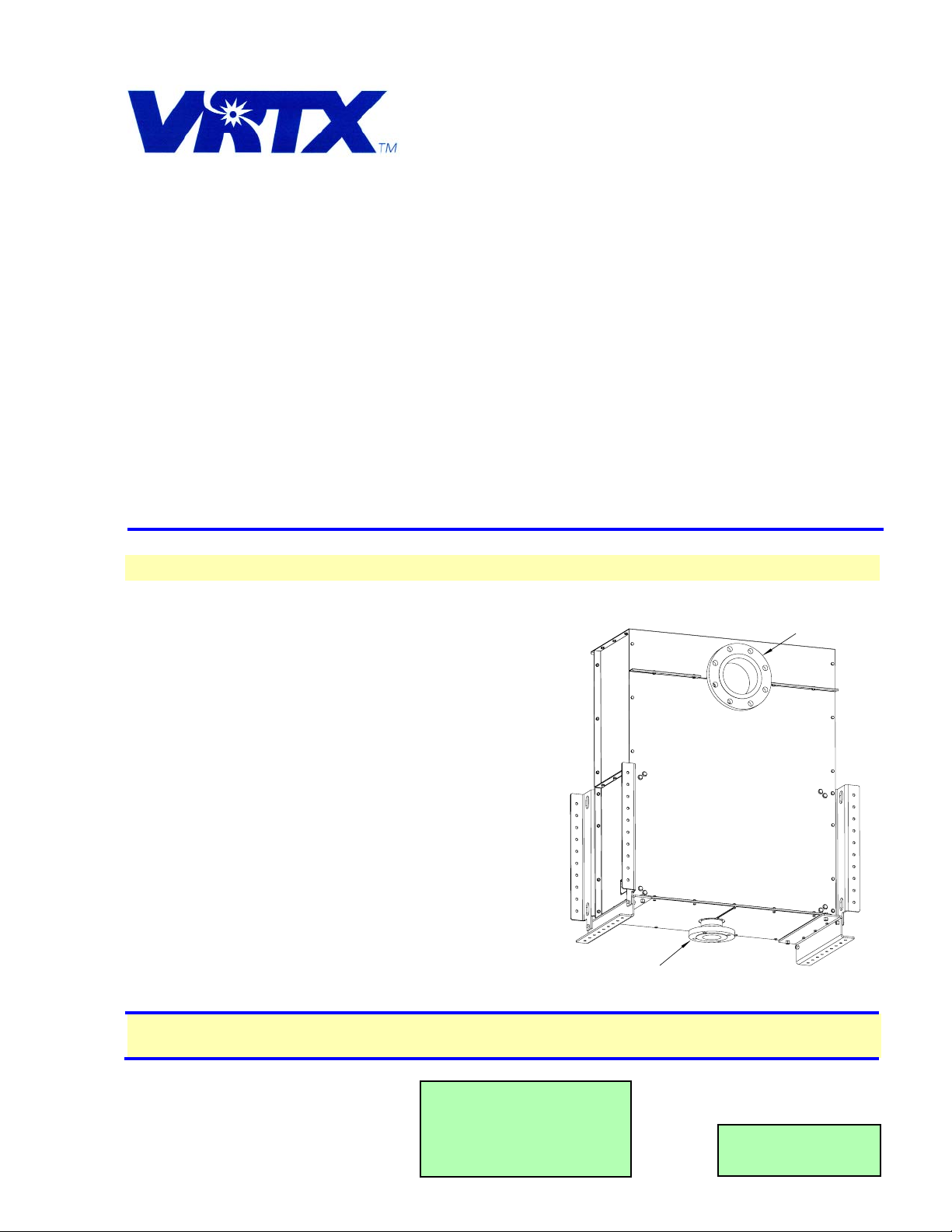
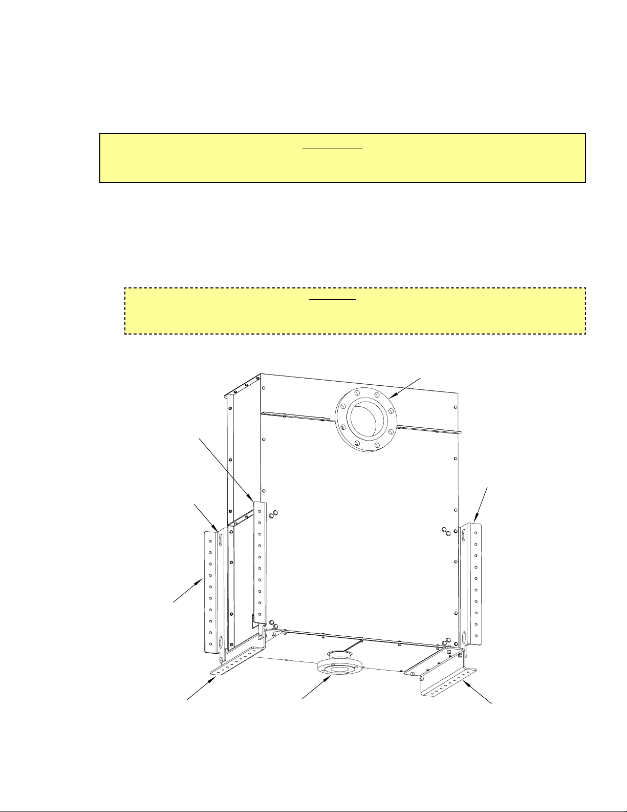
1. LIFTING AND HOISTING VRTX UNIT
1.1 The unit is designed with two (2) lifting bail holes per side mounting rail. Upon hoisting the unit, a
minimum of four (4) holes should be used, with appropriate spreader bars and rigging.
1.2 The unit is also designed to be lifted with a fork lift. When a fork lift is being used for installation, care
should be taken to avoid hitting or damaging the inlet flange, on the bottom of the unit, with the forks.
2. INSTALLATION OF UNIT
IMPORT
ANT
THE UNIT SHOULD BE MOUNTED, AS SHOWN IN FIGURE 1, WITH THE INLET ORIENTED IN A
DOWNWARD POSITION. NO OTHER MOUNTING ORIENTATION IS SUGGESTED.
The unit is designed to be mounted either by the front, rear or bottom mounting rails (see isometric view,
Figure 1).
2.1 If mounting by the front or rear rails (using two rails minimum), a minimum of eight (8) Grade 5, 3/8”
capscrews with metallic lock nuts should be used [two (2) on each end of each rail] for stability.
2.2 If mounted by the bottom rails, a minimum of four (4) Grade 5, 3/8” capscrews with metallic lock nuts
should be used [one (1) on each end of each rail] for stability.
2.3 A bellows type flex coupling is required on both the inlet and outlet plumbing connection.
CAUTION
ENSURE THAT MOUNTING LOCATION WILL ADEQUATELY SUPPORT THE 620 POUND
OPERATING WEIGHT OF THE UNIT.
Mounting Details
Figure 1
OUTLET FLANGE
6 INCH, 150 POUND
REAR MOUNTING RAIL
LIFTING BAIL HOLE
(TYPICAL)
FRONT MOUNTING RAIL
(ONE EACH SIDE)
BOTTOM MOUNTING RAIL
INLET FLANGE
3 INCH, 150 POUND
REAR MOUNTING RAIL
BOTTOM MOUNTING RAIL
Page 4

ASSEMBLED VIEW
1
2
3
2
2
2
3
8
7
6
5
4
7
9
9
10
11
5
7
8
6
12
3
3. ILLUSTRATIONS AND PARTS LISTINGS
3.1 PLUMBING ASSEMBLY
ITEM P
ART NO. DESCRIPTION QUANTITY
1 51-6061 Weldment, Tree, SS 1
2 03-0334 Clamp, RIGIDLITE, 7400, 4
4.00” (Galvanized EPDM
Seal)
3 01-2152 Connector, Pump, 4.00” 2
4 51-5869 Weldment, Center
5 03-0333 Clamp, RIDGIDLITE, 7400, 1
6.00” (Galvanized EPDM
Seal)
6 51-6063 Weldment, End 2
7 06-2895 Label, DO NOT REMOVE 1
8 04-1273 Plug, 1/8 NPT 3
9 02-0309 O-Ring, 2-163 (BUNA-N) 4
(Two per nozzle)
10 10-0592 Nozzle, 250 GPM 2
11 10-0748 Cap, Nozzle2
12 04-1337 Screw, 1/4 - 20 X 1.25 12
NOTE:
All wetted components are 304 or 316
stainless steel, unless otherwise noted.
NOTE:
The Remote VRTX Unit has no
serviceable components.
No spare parts are required for
this unit.
Illustrations and parts listings are
provided for reference purposes
only.
Page 5

3.2 SUPPORT FRAME ASSEMBLY, PART 1
4
ITEM PART NO. DESCRIPTION QUANTITY
1 30-9352 Member, Horizontal, 2 X 2 4
2 04-1461 Screw, 1/4 - 20 X 0.750 8
3 30-9366 Support, Vertical 4
4 04-1272 Nut, Lock, 3/8 - 16 17
5 04-1205 Nut, Lock, 1/4 - 20 8
6 30-9353 Bracket, Bridge 1
7 04-1258 Screw, 3/8 - 16 X 1.000 12
8 04-1343 Washer, Fender, 5
1.250 x 0.406
9 50-0384 Isolator, Sound 5
10 04-1342 Screw, 3/8 - 16 x 2.000 5
11 30-9367 Support, Bridge 4
NOTE:
The Remote VRTX Unit has no
serviceable components.
No spare parts are required for
this unit.
Illustrations and parts listings are
provided for reference purposes
only.
4
ASSEMBLED VIEW
5
7
6
5
4
2
1
3
1
2
4
3
7
3
2
1
5
9
8
10
11
2
1
4
8
5
Page 6

3.3 SUPPORT FRAME ASSEMBLY, PART 2
5
ITEM PART NO. DESCRIPTION QUANTITY
1 30-9357 Rail, Vertical, Right 2
2 30-9349 Cover, Side/Bottom 2
3 04-1461 Screw, 1/4 - 20 X 0.750 22
4 04-1258 Screw, 3/8 - 16 X 1.000 24
5 04-1205 Nut, Lock, 1/4 - 20 22
6 30-9348 Rail, Bottom 2
7 04-1272 Nut, Lock, 3/8 - 16 20
8 30-9365 Rail, Vertical Left 2
NOTE:
The Remote VRTX Unit has no serviceable
components.
No spare parts are required for this unit.
Illustrations and parts listings are provided
for reference purposes only.
ASSEMBLED VIEW
2
1
3
4
1
4
3
7
6
9
7
3
4
8
7
4
2
5
6
Page 7

ASSEMBLED VIEW, FRONT
1
ASSEMBLED VIEW, BACK
2
3
4
5
6
7
8
6
7
9
10
11
6
5
5
5
5
4
4
4
6
8
12
4
INSULATION
INSULATION
INSULATION
6
3.4 INSULATION, INTERIOR AND EXTERIOR PANELS
ITEM PART NO. DESCRIPTION QTY
1 06-2894 Nameplate,VRTX 1
2 04-0072 Rivet, 0.125 X 0.312 4
3 30-9364 Cover, Rear 1
4 04-1460 Screw, 1/4 - 20 X 0.375 27
5 04-1461 Screw, 1/4 - 20 X 0.750 16
6 04-1205 Nut, Lock, 1/4 - 20 57
ITEM P
ART NO. DESCRIPTION QTY
7 04-1357 Screw, 1/4 - 20 x 0.625 22
8 30-9350 Cover, Side/Top 2
9 30-9356 Cover, Bottom/Left 1
10 30-9355 Cover, Bottom/Right 1
11 30-9351 Cover, Front 1
12 30-9370 Cover, Top 11
NOTE:
The Remote VRTX Unit has no
serviceable components.
No spare parts are required for this
unit.
Illustrations and parts listings are
provided for reference purposes only.
Page 8

7
For further Information:
e-mail: vrtx@vrtxtech.com
Or see our Web Site
www.vrtx-technologies.com
TOP VIEW
FRONT VIEW
3.5 VIEWS
SIDE VIEW
BOTTOM VIEW
REAR VIEW
39.17"
(995 mm)
22.20"
(564 mm)
2.00"
(51 mm)
(TYP 8X)
12.50"
(318 mm)
0.08"
(2 mm)
6 INCH, 150 POUND
FLANGE OUTLET
41.69"
(1059 mm)
2.00"
(51 mm)
(TYP 9X)
6.52"
(166 mm)
3.10"
(79 mm)
49.00"
(1245 mm)
9.63"
(245 mm)
41.67"
(1058 mm)
22.20"
(564 mm)
5.63" (143 mm)
2.00"
(51 mm)
(TYP 9X)
0.88" + 0.25"
(22 mm + 6 mm)
39.67"
(1008 mm)
3 INCH, 150 POUND
FLANGE INLET
 Loading...