

Page 1
Model 605 Cold Carbonated Dispenser
Operation Manual
PN: 28-0732/03
600
Lancer Corp.
6655 Lancer Blvd.
San Antonio, Texas 78219
800-729-1500
Technical Support/Warranty: 800-729-1550
custserv@lancercorp.com
lancercorp.com
Manual PN: 28-0732/03
OCTOBER 20, 2009
FOR QUALIFIED INSTALLER ONLY
“Lancer” is the registered trademark of Lancer © 2014 by Lancer, all rights reserved.
Page 2

ABOUT THIS MANUAL
This booklet is an integral and essential part of the product and should be handed over to the operator after the
installation and preserved for any further consultation that may be necessary. Please read carefully the guidelines and
warnings contained herein as they are intended to provide the user with essential information for the continued safe
use and maintenance of the product. In addition, it provides GUIDANCE ONLY to the user on the correct services and
site location of the unit.
The installation and relocation, if necessary, of this product must be carried out by qualied personnel with up-to-date
safety and hygiene knowledge and practical experience, in accordance with current regulations.
TABLE OF CONTENTS
SPECIFICATIONS...............................................................................................................................4
PRE-INTALLATION CHECKLIST........................................................................................................5
WARNINGS/CAUTIONS..................................................................................................................6-9
1. INSTALLATION............................................................................................................................10
1.1 UNPACKING........................................................................................................................10
1.2 UNPACKING INSTALLATION KITS....................................................................................10
1.3 SELECTING A COUNER LOCATION.................................................................................10
1.4 MOUNTING THE DISPENSER...........................................................................................10
1.5 CONNECTING THE DRAIN................................................................................................11
1.6 FILLING UNIT WITH WATER..............................................................................................11
1.7 CONNECTING TO ELECTRICAL POWER.........................................................................11
1.8 CONNECTING TO WATER SUPPLY..................................................................................12
1.9 CONNECTING TO CO2 SUPPLY.......................................................................................12
1.10 CONNECTING TO BAG-IN-BOX (BIB) SYRUP SUPPLY (UNITS WITH BUILT-IN SYRUP
PUMPS)..............................................................................................................................13
1.11 CONNECTING TO REMOTE BIB SYRUP PUMPS............................................................13
1.12 CONNECTING TO REMOTE PRESSURIZED SYRUP SUPPLY......................................13
1.13 PURGING THE CARBONATION SYSTEM........................................................................13
1.14 CONNECTION FOR PLAIN WATER PRODUCT................................................................14
1.15 SETTING 3-WAY ADJUSTABLE BACK BLOCKS FOR PLAIN OR
CARBONATED WATER......................................................................................................14
1.16 ADJUSTING WATER FLOW (LEV®)..................................................................................14
1.17 ADJUSTING WATER TO SYRUP (RATIO) BRIX (LEV®)..................................................15
1.18 VALVE ACCESS (SYRUP MODULE OR SODA MODULE)...............................................15
2. SCHEDULED MAINTANANCE...................................................................................................15
2.1 DAILY...................................................................................................................................15
2.2 WEEKLY..............................................................................................................................15
2.3 MONTHLY............................................................................................................................15
2.4 EVERY SIX MONTHS.........................................................................................................15
2.5 YEARLY...............................................................................................................................16
3. DISPENSER CLEANING AND SANITIZATION..........................................................................16
3.1 GENERAL INFORMATION.................................................................................................16
3.2 CLEANING AND SANITIZING SOLUTIONS.......................................................................16
3.3 AMBIENT PROCESS..........................................................................................................16
3.4 VALVE AND SYSTEM SANITIZING....................................................................................17
3.5 MONTHLY NOZZLE/DIFFUSER SANITIZING ..................................................................17
3.6 CLEANING AND SANITIZING BEVERAGE COMPONENTS - BAG-IN-BOX
SYSTEMS...........................................................................................................................17
2
Page 3

4. TROUBLESHOOTING...........................................................................................................18-24
5. ILLUSTRATIONS, PARTS LISTINGS, AND WIRING DIAGRAMS............................................26
5.1 COMPRESSOR DECK ASSEMBLY..............................................................................26-27
5.2 MINIPUMP ASSEMBLY (FIVE FLAVOR, PN 82-3900).................................................28-29
5.3 FOAM TANK/CABINET ASSEMBLY..............................................................................30-31
5.4 CARBONATOR, WATER/SYRUP LINE ASSEMBLIES.................................................32-33
5.5 CONTROL HOUSING ASSEMBLY (PN 52-3231)...............................................................34
5.6 WIRING DIAGRAM, PN 06-3058........................................................................................35
6. DISPENSER DISPOSAL.............................................................................................................35
3
Page 4
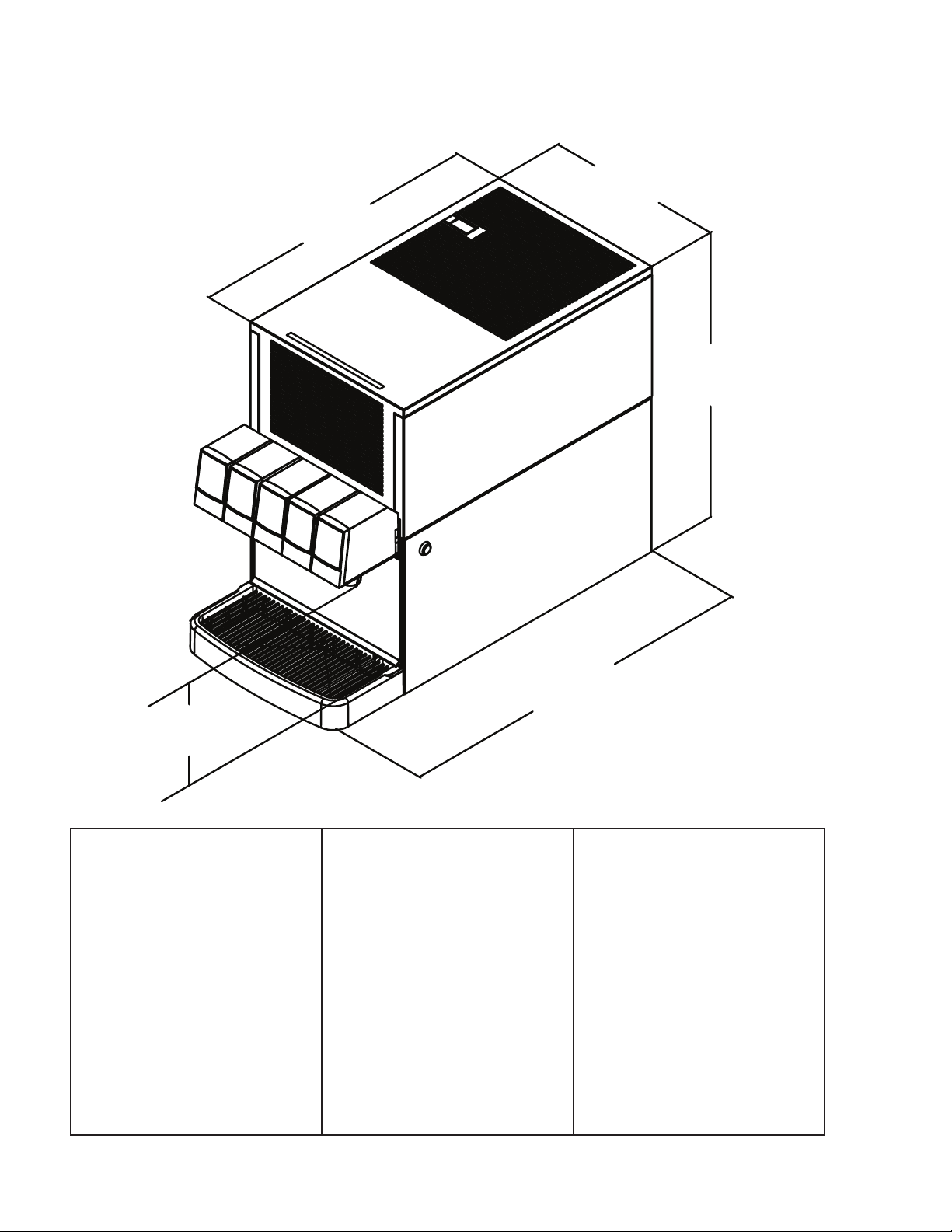
MODEL 605 SPECIFICATIONS
21.4”
(544 mm)
(335 mm)
13.2”
20.6”
(523 mm)
8”
(203 mm)
DIMENSIONS
Width: 13.5 in (343 mm)
Depth: 27.5 in (698 mm)
Height: 21.25 in (539 mm)
SPACE REQUIRED
Left Side: 1 in (25 mm)
Right side: 1 in (25 mm)
Back: 1 in (25 mm)
Top: 8 in (203.2 mm)
ELECTRICAL
230VAC/50Hz/3.5AMPs
WEIGHT
Empty: 125 lbs (56.8 kg)
Operating: 163 lbs (74.1 kg)
Shipping: 140 lbs (63.6 kg)
ICE
Bank Weight: 11-13 lbs
(5-5.9 kg)
FITTINGS
Soda Inlets: 3/8” barb
Brand syrup inlets: 3/8” barb
27.4”
(696 mm)
CARBONATOR WATER SUPPLY
Min ltered water pressure:
50 PSIG (0.345 MPA)
Min owing pressure:
25 PSIG (0.175 MPA)
Max static pressure:
50 PSIG (0.345 MPA)
CARBON DIOXIDE (CO2)
Min pressure:
70 PSIG (0.483 MPA)
Max pressure:
80 PSIG (0.552 MPA)
4
Page 5
PRE-INSTALLATION CHECKLIST
BEFORE GETTING STARTED
Each unit is tested under operating conditions and is thoroughly inspected before
shipment. At the time of shipment, the carrier accepts responsibility for the unit. Upon
receiving the unit, carefully inspect the carton for visible damage. If damage exists, have
the carrier note the damage on the freight bill and le a claim with carrier. Responsibility for
damage to the dispenser lies with the carrier.
TOOLS REQUIRED
Oetiker Pliers Slotted Screwdriver
Tubing Cutters Phillips Screwdriver
Wrench Cordless Drill
POST MIX ACCESSORIES
CO2 Regulator Set CO2 Supply
Beverage Tubing Oetiker Clamps/Fittings
Water Booster Water Regulator
Precision Cutters (if removing/replacing carbonator tank)
BIB SYSTEM
BIB Rack BIB Regulator Set
BIB Syrup Boxes
BIB Connectors - ensure you have the correct connectors for syrup lineup.
CONSIDER LOCATION OF THE FOLLOWING PRIOR TO INSTALL
Water supply lines Drain
Is the countertop level? Heating and air conditioning ducts
Grounded electrical outlet.
Enough space to install the dispenser. Include space for a top-mounted ice machine, if necessary.
Does the top-mounted ice machine have a minimum clearance on all sides?
Located away from direct sunlight or overhead lighting.
Can the countertop support the weight of the dispenser? Be sure to include the weight of an ice
machine (if necessary) plus the weight of the ice.
This unit is not suitable for use in an area where a water jet could be used.
5
Page 6

! !
WARNING/ADVERTENCIA/AVERTISSEMENT
! The dispenser is for indoor use only. This appliance is intended for use in commercial applications such as
restaurants, stores or similar. This unit is not a toy. It should not be used by children or inrm persons without
supervision. This appliance is not intended for use by persons (including children) with reduced physical, sensory
or mental capabilities, or lack of experience and knowledge, unless they have been given supervision or instruction
concerning use of the appliance by a person responsible for their safety. Cleaning and user maintenance shall not
be performed by children without supervision. This unit is not designed to dispense dairy products. The minimum/
maximum ambient operating temperature for the dispenser is 40°F to 90°F (4°C to 32°C). Do not operate unit below
minimum ambient operation conditions. Should freezing occur, cease operation of the unit and contact aurthorized
service technician. Service, cleaning and sanitizing should be accomplished only by trained personnel. Applicable
safety precautions must be observed. Instruction warnings on the product being used must be followed.
! El dispensador sólo debe usarse en interiores. Esta unidad está diseñada para su uso en aplicaciones
comerciales tales como restaurantes, tienda o similares. Esta unidad no es un juguete. No la deben usar niños ni
personas discapacitadas sin supervisión. Esta unidad no está destinada al uso por parte de personas (incluso niños)
con capacidad física, sensorial o mental reducida, o sin experiencia y conocimientos sucientes, a menos que una
persona responsable de su seguridad les haya dado supervisión o capacitación en el uso de la unidad. Limpieza y
mantenimiento de usuario no deberá ser realizada por los niños sin supervisión. Esta unidad no ha sido diseñada
para suministrar productos lácteos. La temperatura ambiente operativa mínima / máxima para el dispensador es de
40°F a 90°F (4°C a 32°C). No opere la unidad por debajo de las condiciones mínimas de funcionamiento ambiente.
En caso de ocurrir congelación, cesar la operación de la unidad y póngase en contacto con el servicio técnico
autorizado. Servicio de limpieza y desinfección debe llevarse a cabo solamente por personal especializado.
Precauciones de seguridad aplicables deben ser observadas. Advertencias de instrucciones en el producto que se
use debe ser seguido.
! Le distributeur est destiné à un usage à l’intérieur seulement. Cet appareil est conçu pour une utilisation dans des
applications commerciales telles que les restaurants, les dépanneurs ou similaires. Cet appareil n’est pas un jouet. Il
ne devrait pas être utilisé par des enfants ou des personnes inrmes sans surveillance. Cet appareil n’est pas destiné
à un usage par des personnes (y compris les enfants) ayant des capacités physiques, sensorielles ou mentales
réduites, ou manquant d’expérience et de connaissances, à moins qu’elles obtiennent de la surveillance ou des
instructions au sujet de l’utilisation de l’appareil de la part d’une personne chargée de leur sécurité. Nettoyage et
entretien de l’utilisateur ne doivent pas être effectués par des enfants sans surveillance. Cet appareil n’est pas conçu
pour distribuer des produits laitiers. La température de service ambiante minimum/maximum pour le
distributeur est de 40°F à 90°F (4°C à 32°C). Ne pas faire fonctionner l’appareil ci-dessous les conditions minimales
de fonctionnement ambiantes. Faut-gel se produisent, cesser l’exploitation de l’appareil et contactez technicien
agréé. Service de nettoyage et de désinfection doivent être effectuées uniquement par du personnel qualié. Les
mesures de sécurité applicables doivent être respectées. Avertissements Instruction sur le produit utilisé doit être
suivie.
6
Page 7
!
This unit has been factory sanitized per Lancer specications.
Listed below are six critical elements which will aid in a successful installation.
1. Fill water bath until water overows from tank overow tube.
2. The carbonator pump motor must be disconnected from the power supply (see Section 1.7) prior to connection to
water supply for initial build up of ice bank. Failure to do so will result in automatic shut off of carbonator (see item
6 below) or damage to the pump.
3. If this dispenser is installed in an area that is susceptible to ±10% variation of the nominal line voltage, consider
installing a surge protector or similar protection device.
4. There is a ve (5) minute delay which prevents the compressor and condenser fan from starting until the delay
has lapsed. If electrical current is interrupted, there is always a ve (5) minute delay before the compressor starts.
5. Supply Water Pressure: Minimum - 25 PSI (0.172 MPA); Maximum - 50 PSI (0.345 MPA); If pressure is over 50
PSIG (0.345 MPA), a water pressure regulator must be used.
6. On units with the built in water regulator, the regulator must be removed if inlet water pressure is less than 25
PSIG. (0.172 MPA)
DISPENSER INSTALLATION HIGHLIGHTS
!
!
Esta unidad ha sido saneada en fabrica por las especicaciones de Lancer.
A continuacion se relacionan 6 puntos importantes para una connecta instalacion.
1. Llene el bano-Maria hasta que el agua se desborde sobre el tubo que controla la derrama del tanque.
2. El motor de la bomba del carbonatador debe desconectarse electricamente (Ver Manual - Seccion 1.7) antes
de conectar el suministro de agua para la formacion inicial del banco de hielo. De no hacerse esto resultaria en
un bloqueo automatico del carbonatador (ver abajo el punto 6) o en danos a la bomba.
3. Si la unidad va a ser instalada en un area en la que puedan darse variaciones de voltage de + 6 - 10% de su
valor nominal, se debe considerar la conveniencia de instalar un estabilizador de corriente o sistema de
proteccion similar.
4. Hay una demora de 5 minutos que evita que el compresor y el abanico del condensador arranquen hasta pasado
ese tiempo. Si hay algun corte en la corriente electrica siempre se producira esa demora de 5 minutos antes de
arrancar el compresor.
5. Presión de suministro del agua de red: Minimo 25 PSI (0.172 MPA); Maximo 50 PSI (0.345 MPA). En unidades
sin regulador de presión incorporado, si la presión del agua es superior a 50 PSIG (0.345 MPA) se debe usar un
regulador de presión.
6. En unidades con regulador de presión incorporado, el regulador debe der eliminado cuando la presión de entrada
de agua sea inferior a 25 PSIG (0.172 MPA).
REGLES DE SECURITE POUR L’NSTALLATION DU DISTRIBUTEUR DE SODAS
!
PUNTOS IMPORTANTES EN LA UNIDAD DISPENSADORA
!
!
La proprètè da cet ensamable est assurè à I’usine sulvant les spècications èmis par Lancer .
Il est essentiel de respecter les 6 points suivants pour l’installation de l’appareil:
1. Remplir le bain-Maire jusqu’a ce que l’eau dèborde par le tuyau de trop-plein du rèservoir.
2. Le moteur de la pompe du carbonateur doit etre dèbranchè de l’alimentation èlectrique (Voir le manuel,
Section 1.7) avant l’arrivèe de l’eau pour la formation initiale de la glace. Oublier ou nègliger cette opèration
provoquera l’arret automatique du carbonateur (voir le point 6 cidessous) ou causera des dommages à la pompe.
3. Si le distributeur es installè dans une zone ou la tension èlectrique nominale est susceptible de variations de (+)
10%, il est conseillè d’installer un appaeil de protection contre les sautes de courant.
4. Un d’lai de 5 minutes empeche le compresseur et la ventilation du condesateur de se mettre en marche avant
que ce lees de temps ne se soit ècoulè. Lorsque le courant èlectrique es interrompu, il y a toujours un dèlai de 5
minutes avant que le presseur ne se mette en.
5. Pression de l’eau: Minimum 25 PSI (0.172 MPA); Maximo 50 PSI (0.345 MPA). Sur les unitès qui n’ont pas de
règulateur de pression d’eau incorprè, si la pression d’H2O est supèrieure à 50 PSIG (0.345 MPA), un règulateur
de pression d’eau doit etre utilsisè.
6. Sur les unitès avec règulateur d’eau incorporè, le règulateur doit etre enlevè si la pression d’arrivve est inferièure
à 25 PSIG (0.172 MPA)
7
Page 8
ELECTRICAL WARNING/ADVERTENCIA ELÉCTRICA/
F F
AVERTISSEMENT ÉLECTRIQUE
F Check the dispenser serial number plate for correct electrical requirements of unit. Do not plug into a wall
electrical outlet unless the current shown on the serial number plate agrees with local current available. Follow
all local electrical codes when making connections. Each dispenser must have a separate electrical circuit. Do not
use extension cords with this unit. Do not ‘gang’ together with other electrical devices on the same outlet. The
keyswitch does not disable the line voltage to the transformer primary. Always disconnect electrical power to the unit
to prevent personal injury before attempting any internal maintenance. The resettable breaker switch should not
be used as a substitute for unplugging the dispenser from the power source to service the unit. Only qualied
personnel should service internal components of electrical control housing. Make sure that all water lines are tight
and units are dry before making any electrical connections!
F Verique la placa con el número de serie del dispensador, donde encontrará los requisitos eléctricos correctos
de la unidad. No enchufe la unidad en un tomacorriente de pared a menos que la corriente indicada en la placa con
el número de serie concuerde con la corriente local disponible. Al hacer las conexiones, respete todos los códigos
eléctricos locales. Cada dispensador debe tener un circuito eléctrico independiente. No use extensiones con esta
unidad. No la conecte junto con otros dispositivos eléctricos al mismo tomacorriente. El interruptor de llave no corta
el voltaje de línea al transformador primario desconecte siempre la alimentación eléctrica a la unidad para evitar
lesiones personales antes de tratar de realizar tareas de mantenimiento. El disyuntor de sobrecarga
reseteable no se debe usar como sustituto para desenchufar el dispensador de la fuente de alimentación para
realizar tareas de servicio de la unidad. El servicio de los componentes internos de la caja de control eléctrico debe
conarse exclusivamente a personal calicado. Asegúrese de que todas las líneas de agua estén ajustadas y las
unidades estén secas antes de hacer conexiones eléctricas.
F Examinez la plaque de numéro de série du distributeur pour connaître les bonnes exigences en matière
d’électricité pour l’appareil. Ne le branchez pas à une prise électrique murale à moins que le courant indiqué sur la
plaque de numéro de série corresponde au courant local disponible. Respectez tous les codes électriques locaux
lorsque vous faites des connexions. Chaque distributrice doit avoir un circuit électrique séparé. N’utilisez pas
de cordons prolongateurs avec cet appareil. Ne pas le brancher avec d’autres appareils électriques sur la même
prise. L’interrupteur à clé ne coupe pas la tension secteur au transformateur primaire. Débranchez toujours le courant
électrique à l’appareil, an de prévenir des blessures, avant de faire un entretien interne quelconque. Le disjoncteur
réarmable ne devrait pas être utilisé au lieu de débrancher le distributeur de la source d’alimentation en électricité
pour faire de l’entretien/une réparation de l’appareil. Seul le personnel qualié devrait faire l’entretien/la réparation
des composants internes dans le logement des commandes électriques. Assurez-vous que toutes les conduites
d’eau sont étanches et que les appareils sont secs avant de faire des connexions électriques!
CO2/CARBON DIOXIDE /El ANHÍDRIDO CARBÓNICO/
5 5
DIOXYDE DE CARBONE
5 Carbon Dioxide (CO2) is a colorless, noncombustible gas with a light pungent odor. High percentages of CO2 may
displace oxygen in the blood. Prolonged exposure to CO2 can be harmful. Personnel exposed to high concentrations
of CO2 gas will experience tremors which are followed by a loss of consciousness and suffocation. If a CO2 gas leak
is suspected, immediately ventilate the contaminated area before attempting to repair the leak. Strict attention must
be observed in the prevention of CO2 gas leaks in the entire CO2 and soft drink system.
5 El anhídrido carbónico (CO2) es un gas incoloro, no combustible, con un olor pungente ligero. Altos porcentajes
de CO2 en la sangre pueden desplazar el oxígeno en la sangre. La exposición prolongada al CO2 puede ser nociva.
El personal expuesto a concentraciones altas de CO2 sufre temblores seguidos de la pérdida de la consciencia y
sofocación. Si se sospecha que existe una pérdida de CO2, ventile el área contaminada antes de tratar de reparar
la pérdida. Hay que prestar suma atención para evitar pérdidas de CO2 en todo el sistema de CO2 y de bebidas
gaseosas.
5 Le dioxyde de carbone (CO2) est plus lourd que l’air et déplace l'oxygène. Le CO2 est un gaz incolore et
incombustible, ayant une odeur un peu âcre. Des concentrations fortes de CO2 peuvent déplacer l'oxygène dans le
sang. Une exposition prolongée au CO2 peut être nocive. Le personnel exposé à de fortes concentrations de CO2
gazeux éprouvera des tremblements, suivis rapidement d'une perte de conscience et de suffocation. On doit faire très
attention de prévenir les fuites de CO2 gazeux dans le système entier de CO2 et de boisson gazeuse. Si on suspecte
qu'il y a une fuite de CO2 gazeux, aérez le secteur contaminé immédiatement avant d'essayer de réparer la fuite.
8
Page 9
AUTOMATIC AGITATION/AGITACIÓN AUTOMÁTICA/
! Units are equipped with an automatic agitation system and will activate unexpectedly. Do not place hands or
foreign objects in the water bath tank. Unplug the dispenser during servicing, cleaning, and sanitizing. To avoid
personal injury, do not attempt to lift the dispenser without assistance. For heavier dispensers, use a mechanical lift.
! Las unidades están equipadas con un sistema automático de agitación, por lo que se pueden activar
repentinamente. No ponga las manos ni objetos extraños en el compartimiento donde se guarda el hielo. Durante el
servicio, la limpieza y la esterilización, desenchufe el dispensador. Para evitar lesiones personales, no trate de
levantar el dispensador sin ayuda. Para los dispensadores más pesados, use un elevador mecánico.
! Les appareils sont équipés d’un système d’agitation automatique qui s’activera de manière inattendue. Ne mettez
pas les mains ou des corps étrangers dans le compartiment d’entreposage de glace. Débranchez le distributeur
pendant l’entretien/la réparation, le nettoyage et l’aseptisation. Pour éviter des blessures, n’essayez pas de soulever
le distributeur sans aide. Pour les distributeurs plus lourds, utilisez un chariot élévateur.
! !
WATER NOTICE/AGUA AVISO/ PRÉAVIS DE L’EAU
! Provide an adequate potable water supply. Water pipe connections and xtures directly connected to a potable
water supply must be sized, installed, and maintained according to federal, state, and local laws. The water
supply line must be at least a 3/8 inches (9.525 mm) pipe with a minimum of 25 PSI (0.172 MPA) line pressure, but
not exceeding a maximum of 50 PSI (0.345 MPA). Water pressure exceeding 50 PSI (0.345 MPA) must be reduced
to 50 PSI (0.345 MPA) with the provided pressure regulator. Use a lter in the water line to avoid equipment damage
and beverage off-taste. Check the water lter periodically, as required by local conditions. The water supply must be
protected by means of an air gap, a backow prevention device (located upstream of the CO2 injection system) or
another approved method to comply with NSF standards. A leaking inlet water check valve will allow carbonated
water to ow back through the pump when it is shut off and contaminate the water supply. Ensure the backow
prevention device complies with ASSE and local standards. It is the responsibility of the installer to ensure
compliance.
! Proporcione un suministro adecuado de agua potable. La línea de suministro de agua debe ser de una tubería de
por lo menos 3/8 pulgadas (9.525 mm) con una presión de línea mínima de 25 PSI (0.172 MPA) , pero sin superar
el máximo de 50 PSI (0.345 MPA). La presión de agua que supere los 50 PSI se debe reducir a 50 PSI (0.345 MPA)
con un regulador de presión. Use un ltro en la línea de agua para evitar daños al equipo y cierto sabor raro en las
bebidas. Verique periódicamente el ltro de agua de acuerdo con las condiciones imperantes. El suministro de
agua debe estar protegido por una separación de aire, un dispositivo de prevención del contraujo (situado antes del
sistema de inyección de CO2) u otro método aprobado para cumplir las normas NSF. Si la válvula de retención de
entrada de agua tuviera pérdidas, permitiría el contraujo del agua carbonatada a través de la bomba cuando se la
detiene y contaminaría el suministro de agua. Asegúrese de que el dispositivo de prevención del contraujo cumpla
con las normas locales y de ASSE. Es responsabilidad del instalador cumplir con estos requisitos.
! Fournissez une alimentation en eau potable adéquate. Les connexions et les dispositifs de conduite d’eau
con- nectés directement à une alimentation en eau potable doivent être calibrés, installés et maintenus selon les lois
fédérales, provinciales et locales. La conduite d’alimentation en eau doit être un tuyau d’au moins 3/8 pouces (9.525
millimètres) avec une pression de ligne minimum de 25 LPC (0.172 MPA) , mais ne doit pas dépasser un maximum
de 50 LPC (0.345 MPA). Une pression d’eau de plus de 50 LPC (0.345 MPA) doit être réduite à 550 LPC (0.345
MPA) avec le régu- lateur de pression fourni. Utilisez un ltre dans la conduite d’eau pour éviter des dommages à
l’équipement et un goût des boissons qui n’est pas juste. Vériez le ltre à eau périodiquement, selon les exigences
des conditions locales. L’alimentation en eau doit être protégée au moyen d’un intervalle d’air, un disconnecteur
hydraulique (situé en amont du système d’injection de CO2) ou une autre méthode approuvée pour se conformer
aux normes de la NSF. Un clapet antiretour pour l’eau entrante qui fuie permettra à l’eau gazeuse de repasser par
la pompe quand elle est fermée et de contaminer l’alimentation en eau. Assurez-vous que le disjoncteur hydraulique
soit conforme aux normes de l’ASSE et locales. L’installateur est responsable d’assurer la conformité.
9
Page 10

1. INSTALLATION
1.1 UNPACKING
WARNING TO AVOID PERSONAL INJURY OR DAMAGE, DO NOT ATTEMPT TO LIFT A UNIT WITHOUT HELP. FOR
HEAVIER UNITS, USE OF A MECHANICAL LIFT MAY BE APPROPRIATE. UNITS ARE EQUIPPED WITH AUTOMATIC
AGITATION. THE UNIT MAY ACTIVATE UNEXPECTEDLY. DO NOT PLACE HANDS, OR FOREIGN OBJECTS INTO
THE ICE STORAGE COMPARTMENT. UNPLUG DISPENSER FROM THE POWER SOURCE , WHEN UNIT IS BEING
SERVICED, CLEANED, OR SANITIZED.
ADVERTENCIA EVITE LAS LESIONES PERSONALES, NO TRATE DE LEVANTAR EL DISPENSADOR SIN AYUDA.
PARA LOS DISPENSADORES MÀS PESADOS USE UN ELEVADOR MECÁNICO. LAS UNIDADES EQUIPADAS CON
AGITACIÓN AUTOMÁTICA SE ACTIVAN REPENTINAMENTE. NO PONGA LAS MANOS NI OBJETOS EXTRANOS EN
EL COMPARTIMIENTO DE ALMACENAMIENTO DE HIELO. DESENCHUFE EL DISPENSADOR DURANTE TAREAS
!
A. Cut banding and remove.
B. Remove top portion of carton by lifting up.
C. Remove accessory kit and loose parts from top packaging.
D. Remove side inserts.
E. Lift unit up by plywood shipping base and remove lower portion of carton.
F. Inspect unit for concealed damage and if evident notify delivering carrier and le a claim.
G. Remove plywood shipping base from unit by moving unit so that one side is off the countertop
or table allowing access to screws on the bottom of the plywood shipping base.
NOTE: If unit is to be transported, it is advisable to leave unit secured to plywood shipping base.
H. If Unit is to be installed with optional legs, assemble legs to unit by tilting unit. DO NOT LAY
UNIT ON ITS SIDE OR BACK.
1.2 UNPACKING INSTALLATION KITS
A. Inspect kits for concealed damage and if evident, notify delivering carrier and le a claim.
B. Each kit contains a list of the parts and a drawing showing the proper assembly of the parts.
1.3 SELECTING A COUNTER LOCATION
A. Select a location close to a properly grounded electrical outlet and water supply that meets the
requirements on the specication page.
DE SERVICIO, LIMPIEZA Y ESTERILIZACIÓN.
AVERTISSEMENT POUR ÉVITER DES BLESSURES OU DES DOMMAGES, N’ESSAYEZ PAS DE SOULEVER UNE
UNITÉ SANS AIDE. POUR LES UNITÉS PLUS LOURDES, L’UTILISATION D’UN ASCENSEUR MÉCANIQUE PEUT
ÊTRE APPROPRIÉE. LES UNITÉS SONT ÉQUIPÉES D’UNE AGITATION AUTOMATIQUE. L’UNITÉ PEUT S’ACTIVER
DEMAINÉRE INATTENDUE. NE PLACEZ PAS LES MAINS, OU DES CORPS ÉTRANGERS DANS LE
COMPARTIMENT DE STOCKAGE DE GLACE. DÉBRANCHEZ LE DISTRIBUTEUR DE LA SOURCE D’ALIMENTATION
EN ÉLECTRICITÉ QUAND L’UNITÉ EST ENTRETENUE, NETTOYÉE OU ASEPTISÉE.
WARNING FAILURE TO MAINTAIN SPECIFIED CLEARANCE WILL CAUSE THE COMPRESSOR TO OVERHEAT
AND WILL RESULT IN COMPRESSOR FAILURE.
ADVERTENCIA SI NO DEJA EL ESPACIO LIBRE ESPECIFICADO EL COMPRESOR PUEDE RECALENTAR Y
FALLAR.
!
AVERTISSEMENT LE FAIT DE NE PAS MAINTENIR LE DÉGAGEMENT SPÉCIFIÉ FERA SURCHAUFFER LE
COMPRESSEUR ET AURA COMME CONSÉQUENCE UNE DÉFAILLANCE DU COMPRESSEUR.
B. Condenser air is drawn in and discharged out of the top of the unit. A minimum of eight inches
(203 mm) clearance must be maintained over the top of the unit.
C. The dispenser may be susceptible to EMC electrical interference. If this occurs, relocate the
dispenser to an alternative location. If interference is still present, contact Lancer Technical
Support.
1.4 MOUNTING THE DISPENSER
A. The dispenser is designed to be permanently mounted and sealed to the counter.
NOTE: NSF-listed units must be 1) sealed to the counter using FDA-approved silicone or 2)
elevated above the counter in accordance with NSF directives.
B. When permanently bolting the dispenser to the countertop, seal the dispenser base to
countertop with a bead of clear, FDA-approved, silicone caulk or sealant which provides a
smooth and easily-cleaned bond to the counter.
10
Page 11

1.5 CONNECTING THE DRAIN
A. Remove cup rest. Lift splash plate up and pull out and down on the bottom to remove.
B. Remove the drip tray from the unit and connect the drain tube to the drain tting located on the
back.
C. Route the drain tube to a suitable drain.
D. Reinstall the drip tray, splash plate, and cup rest.
1.6 FILLING UNIT WITH WATER
A. Remove the top cover from the unit.
B. Locate the ll tube (next to the carbonator relief valve).
C. Using a funnel or tube, ll the water bath compartment with water until it ows out of the
overow tube into the drip tray.
WARNING THE WATER BATH COMPARTMENT MUST BE FILLED WITH WATER BEFORE PLUGGING IN THE
DISPENSER. OTHERWISE, THE COMPRESSOR DECK AND CONDENSER FAN WILL NOT OPERATE.
ADVERTENCIA EL COMPARTIMIENTO DE BAÑO DE AGUA DEBE SER LLENADO CON AGUA ANTES DE
CONECTAR EL DISTRIBUIDOR. DE OTRA MANERA, LA CUBIERTA DEL COMPRESOR Y VENTILADOR DEL
CONDENSADOR NO FUNCIONAR.
!
AVERTISSEMENT LE COMPARTIMENT DE BAIN D’EAU DOIT ÊTRE REMPLI D’EAU AVANT BRANCHER LE
DISTRIBUTEUR. AUTREMENT, LE COMPRESSEUR ET LE CONDENSEUR PONT VENTILATEUR NE FONCTIONNE.
1.7 CONNECTING TO ELECTRICAL POWER
NOTE: Adhere to the ELECTRICAL Warnings/Cautions, Page 8.
GROUNDING WARNING THE DISPENSER MUST BE PROPERLY ELECTRICALLY GROUNDED TO AVOID
SERIOUS INJURY OR FATAL ELECTRICAL SHOCK. THE POWER CORD HAS A THREE-PRONG GROUNDED
PLUG. IF A THREE-HOLE GROUNDED ELECTRICAL OUTLET IS NOT AVAILABLE, USE AN APPROVED METHOD TO
GROUND THE UNIT. FOLLOW ALL LOCAL ELECTRICAL CODES WHEN MAKING CONNECTIONS. EACH
DISPENSER MUST HAVE A SEPARATE ELECTRICAL CIRCUIT. DO NOT USE EXTENSION CORDS. DO NOT
CONNECT MULTIPLE ELECTRICAL DEVICES ON THE SAME OUTLET.
ADVERTENCIA, PUESTA A TIERRA ES NECESARIO PONER A TIERRA ELÉCTRICAMENTE EL
DISPENSADOR PARA EVITAR LESIONES GRAVES E INCLUSO ELECTROCHOQUES FATALES. EL CABLE DE
ALIMENTACIÓN TIENE UN ENCHUFE PUESTO A TIERRA DE 3 CLAVIJAS. SI NO SE DISPONE DE UN TOMA
ELÉCTRICO CONECTADO A TIERRA DE TRES AGUJEROS, USE UN MÉTODO APROBADO PARA PONER A TIERRA
LA UNIDAD. AL HACER LAS CONEXIONES, RESPETE TODOS LOS CÓDIGOS ELÉCTRICOS LOCALES. CADA
F
A. If the unit is equipped with a built-in carbonator, disconnect the power supply to the carbonator
B. Check the dispenser serial number plate for correct electrical requirements of unit. Do not plug
C. Route the power supply cord to a grounded electrical outlet of the proper voltage and amperage
DISPENSADOR DEBE TENER UN CIRCUITO ELÉCTRICO INDEPENDIENTE. NO USE CABLES DE EXTENSIÓN. NO
CONECTE VARIOS DISPOSITIVOS ELÉCTRICOS AL MISMO TOMACORRIENTE.
EXIGENCES DE MISE À LA TERRE LA DISTRIBUTRICE DOIT ÊTRE MISE À LA TERRE ÉLECTRIQUEMENT
CORRECTEMENT POUR ÉVITER DES BLESSURES GRAVES OU UNE DÉCHARGE ÉLECTRIQUE MORTELLE. LE
CORDON D’ALIMENTATION A UNE FICHE À TROIS BRANCHES MISE À LA TERRE. SI AUCUNE PRISE DE
COURANT ÉLECTRIQUE À TROIS TROUS N’EST DISPONIBLE, UTILISEZ UNE MÉTHODE APPROUVÉE POUR
METTRE L’UNITÉ À LA TERRE. RESPECTEZ TOUS LES CODES ÉLECTRIQUES LOCAUX LORSQUE VOUS FAITES
DES CONNEXIONS. CHAQUE DISTRIBUTRICE DOIT AVOIR UN CIRCUIT ÉLECTRIQUE SÉPARÉ. N’UTILISEZ PAS
DE CORDONS PROLONGATEURS. NE BRANCHEZ PAS PLUSIEURS APPAREILS ÉLECTRIQUES À LA MÊME PRISE
DE COURANT.
motor by disconnecting the designated connector located near the top of the electrical control
box on the refrigeration deck.
into wall electrical outlet unless the current shown on the serial number plate agrees with
local current available.
rating, and plug in the unit. This will turn on the refrigeration system and allow it to start cooling
while completing the rest of the installation. The agitator motor will start immediately, but the
compressor and fan motor will not start until the ve (5) minute delay has elapsed.
CAUTION FAILURE TO DISCONNECT THE MOTOR POWER SUPPLY WILL DAMAGE THE CARBONATOR MOTOR,
THE PUMP AND VOID THE WARRANTY.
F
PRECAUCIÓN SI NO DESCONECTA LA ALIMENTACIÓN ELÉCTRICA DEL MOTOR PODRÍAN DAÑARSE LA BOMBA
Y EL MOTOR DEL CARBONATADO Y ANULAR LA GARANTÍA.
ATTENTION LE FAIT DE NE PAS MAINTENIR LE DÉGAGEMENT SPÉCIFIÉ FERA SURCHAUFFER LE
COMPRESSEUR ET AURA COMME CONSÉQUENCE UNE DÉFAILLANCE DU COMPRESSEUR.
11
Page 12

1.8 CONNECTING TO WATER SUPPLY
NOTE: Adhere to the WATER SUPPLY Warnings/Cautions, Page 9.
WARNING IF THE WATER SOURCE EXCEEDS 50 PSIG (0.345 MPA), USE A WATER REGULATOR KIT TO LIMIT
WATER PRESSURE TO 50 PSIG (0.345 MPA). FAILURE TO USE A REGULATOR WILL RESULT IN IMPROPER
PERFORMANCE OF THE DISPENSER.
ADVERTENCIA SI LA FUENTE DE AGUA SUPERA LOS 50 PSIG (0.345 MPA), UTILICE UN KIT REGULADOR DE
AGUA PARA LIMITAR LA PRESIÓN DE AGUA A 50 PSIG (0.345 MPA). NO USAR UN REGULADOR DARÁ LUGAR
!
A. Using appropriate tubing and ttings, connect tubing assembly to water source. DO NOT
CONNECT TO DISPENSER AT THIS TIME.
B. Flush water supply line thoroughly.
NOTE: If the water source is above 50 PSIG (0.345 MPA), cut tubing assembly and install a
water regulator. This unit meets NSF requirements for backow prevention for internally carbonated
C. Route tubing through a hole in the counter or through an opening in the rear of the dispenser.
Route tubing through the area behind the splash plate to the carbonator area. Connect to water
inlet tting.
D. Leave 12 inches (304.8 mm) of extra tubing length below the counter for servicing and moving
the dispenser.
E. Turn on water supply. Check for leaks.
F. Set to 50 PSIG (0.345 MPA) static pressure.
1.9 CONNECTING THE CO2 SUPPLY
A. Connect the high pressure CO2 regulator assembly to the CO2 cylinder. Use a new CO2 tank
washer if the regulator does not have built-in o-ring seal.
B. Place the CO2 cylinder in service location under counter and secure it with a safety chain.
C. Using appropriate tubing and ttings, connect tubing assembly to tank mount regulator using a
are seal washer (PN 05-0011). Use a back-up wrench to prevent damage to the regulator
assembly.
D. Route the gas line through a hole in the counter or through the opening in the rear of the
dispenser into the area behind the splash plate.
E. Leave 12 inches (304.8 mm) of extra tubing length below the counter for servicing and moving
the dispenser.
F. Remove the protective cap from the elbow on the back of the CO2 manifold (located on top of
minipumps on left side of unit) and connect the CO2 supply line (for units with internal syrup
pumps).
MALA EJECUCIÓN DEL DISPENSADOR.
AVERTISSEMENT SI LA SOURCE DE L’EAU DÉPASSE 50 PSIG (0.345 MPA), UTILISER UN KIT DE RÉGULATEUR
D’EAU POUR LIMITER LA PRESSION EAU A 50 PSIG (0.345 MPA). NE PAS UTILISER UN REGULATEUR
ENTRAÎNERA LA MAUVAISE EXÉCUTION DU DISTRIBUTEUR.
beverage dispensers. It is the responsibility of the installer to ensure compliance with any additional
federal, state or local codes.
WARNING DO NOT TURN ON THE CO2 SUPPLY AT THIS TIME.
ADVERTENCIA NO CONECTE TODAVÍA LA ALIMENTACIÓN DE CO2.
5
G. If the dispenser does not have internal syrup pumps, remove the cap from the CO2 barb on the
carbonator relief valve and connect to tubing.
AVERTISSEMENT N’OUVREZ PAS L’ALIMENTATION EN CO2 À CE MOMENT.
12
Page 13

1.10 CONNECTING TO BAG-IN-BOX (BIB) SYRUP SUPPLY (UNITS WITH BUILT-IN SYRUP PUMPS)
NOTE: Cut the syrup inlet tubing shipped with the installation kit into pieces eight feet (2.4M)
long. These lines can be extended up to a maximum of 12 feet (3.7 M). The maximum height of the
pumps above the lowest BIB package should not exceed eight feet (2.4M). If either the height of the
pumps or the length of the inlet line limitations are exceeded, use remote syrup pumps or
pressurized syrup containers.
A. Remove the protective caps from the syrup pump inlets and connect syrup inlet tube
assemblies furnished in the installation kit to the syrup pumps. Lubricate o-rings before installation
using an FDA-approved lubricant or water. Be careful not to cut o-rings when installing in pump.
B. Mark syrup tube assemblies at BIB hose connector end with product ID tape.
C. Route the syrup supply tubes from the unit through hole in counter or through opening in the
rear of the dispenser to the BIB syrup supply.
D. Dip the hose connectors in a cup of warm water.
E. Attach the BIB hose connectors to the appropriate syrup flavor.
1.11 CONNECTING TO REMOTE BIB SYRUP PUMPS
A. Locate the remote BIB syrup supply and pumps.
B. Attach the syrup supply tubes to the dispenser’s syrup inlet fittings (located behind the splash
plate) using a 1/4” oetiker clamp for each syrup flavor.
C. Route the syrup supply tubes to the remote syrup pumps.
D. Complete installation of the remote syrup pump system following the manufacturer’s
instructions.
1.12 CONNECTING TO REMOTE PRESSURIZED SYRUP SUPPLY
A. Connect the high pressure CO2 regulator assembly to the CO2 cylinder. Use a new CO2 tank
washer if the regulator does not have built-in o-ring seal.
B. Place the CO2 cylinder in an easily-accessed location (for example, under the counter) and
secure the CO2 cylinder with a safety chain.
C. Using tubing and fittings from the installation kit, connect the tubing assembly to the tank mount
regulator using a flare seal washer (PN 05-0011). Use a back-up wrench to prevent damage to
the regulator assembly.
D. Locate the five gallon (figal) syrup containers and the CO2 cylinder and regulator set.
E. Attach the syrup supply tube assembly to the dispenser’s syrup inlet fittings (located behind the
splash plate) using a 21/32 inch (17.0 mm) oetiker clamp for each syrup flavor.
F. Route the syrup supply tubes to the figal syrup containers and attach to the appropriate syrup
flavor.
G. Attach a CO2 supply line from each of the figal syrup containers to the low pressure regulator
and pressurize the containers.
1.13 PURGING THE CARBONATION SYSTEM
A. The relief valve for the built-in carbonator is located under the top cover behind the faucet plate
on the right side of the dispenser. Lift the yellow lever on the top of the relief valve until water
ows from the holes in the relief valve. Release the relief valve. If supply pressure is low, it may
be necessary to reconnect power to the pump and unplug the carbonator probe from the board
until water ows from the relief valve.
B. Reconnect the power supply to the carbonator pump.
C. Decrease the CO2 regulator pressure adjusting screw all the way. Open the CO2 cylinder
handle slowly. Turn the CO2 pressure regulator up slowly to 75 PSIG (0.517 MPA).
D. Open a dispensing valve until water and syrup are owing steadily from the valve.
E. Repeat Step “D” for each avor.
F. Check all of the unit’s syrup, water and CO2 connections for leaks. Repair if necessary.
NOTE: To check for CO2 leaks, close the valve on the CO2 cylinder and observe if the pressure
to the system drops with the cylinder valve closed for ve minutes. Open the cylinder valve after
check.
G. Replace the unit’s top cover, splash plate and cup rest.
13
Page 14

1.14 CONNECTION FOR PLAIN WATER PRODUCT
I.D. PANEL
(Shown in
open position)
COVER SCREW
NOZZLE (WITH
DIFFUSER INSIDE)
FLOW CONTROL
SYRUP
DecreaseIncrease
FLOW CONTROL
WATER
DecreaseIncrease
If a plain water product is desired, make sure the center water module is connected to the center
plug (marked “WATER”) on the PCB. Then follow the procedure which follows:
1.15 SETTING 3-WAY ADJUSTABLE BACK BLOCKS FOR PLAIN OR CARBONATED WATER
A. For a ve-valve unit, valve 3 can be set
to deliver either plain or carbonated
TOP VIEWS
(SHUT-OFF ORIENTATION)
water. Refer to Figure 1.
B. The shut-off stem on the left side of the
back block controls the ow of plain or
carbonated water. The stem has a
straight side and a double curved side
when looking down at the back block.
To set the adjustable back block to
3 - WAY BACK BLOCK
REAR VIEW
SY S
PW
PLAIN WATER ON
deliver plain water, turn the shut-off
stem to where the straight side of the
stem is facing to the left. To set the
back block to deliver carbonated
water, turn the shut-off stem to where
the straight side faces to the right.
LEGEND:
SY = SYRUP LINE
S = SODA LINE
PW = PLAIN WATER LINE
CARB. WATER ON
When the shut-off stem is at its
midpoint, with the straight side facing
forward, the ow of either plain or
PN 06-2874
VALVE CLOSED
carbonated water is shut off.
C. Ensure the shut-off stem is fully turned to
the desired position or the ow of water
Setting 3-Way Adjustable Back Blocks
Figure 1
will be restricted.
D. Remove valve cover from valve 3.
E. Connect the 1/4” fast-on from the water booster harness to the black side terminal on the
valve coil .
1.16 ADJUSTING WATER FLOW (LEV®)
A. The water ow can be adjusted between 1.25 oz/sec (37 ml/sec)
and 2.50 oz/sec (74 ml/sec) on all dispensing valves using the
following procedures.
B. The refridgeration unit should have been running for at least one
(1) hour before you attempt to brix the valves. The drink
temperature should be no higher than 40°F (4.4°C) when the brix
is set. This is best done after the unit has made
an ice bank.
C. Slide up ID panel until ow controls are exposed
(see Figure 2)
D. Remove nozzle by twisting counter clockwise and
pulling down.
E. Remove diffuser by pulling down.
F. Install Lancer (yellow) syrup separator (PN 54-0031) in place of
nozzle.
G. Activate dispensing valve to ll separator syrup tube.
H. Hold a Lancer brix cup under the syrup separator and dispense
water and syrup into cup for four (4) seconds. Divide number of
ounces (ml) of water in cup by four (4) to determine water ow
rate per second
I. To obtain the proper ow, use a screwdriver to adjust water ow
control (see Figure 2).
J. Repeat process for each valve.
Figure 2
Typical Valve Adjustment, LEV®
14
Page 15

1.17 ADJUSTING WATER TO SYRUP (RATIO) BRIX (LEV®)
A. Hold the Lancer brix cup under the syrup separator and activate valve. Check brix.
B. To obtain the proper brix, use screwdriver to adjust syrup ow control (see Figure 2).
C. Once proper ratio is obtained repeat to verify.
D. Remove syrup separator (PN 54-0031 installed in Section 1.16.F above).
E. Install diffuser and nozzle.
F. Slide down ID panel.
G. Repeat process for each valve.
1.18 VALVE ACCESS (SYRUP MODULE OR SODA MODULE)
A. Removal from Back Block
1. Raise valve shroud and lock in place.
2. Turn back block shut-off to the closed position (counterclockwise rotation).
3. Lower shroud and activate the valve pushbutton to relieve pressure.
4. Raise valve shroud and lock in place again.
5. Unplug valve harness from PCB.
6. Raise valve retainer.
NOTE: The retainer cannot be pulled up until the back block shut-off is properly closed.
7. Pull the valve off of the back block.
B. Mounting on Back Block
CAUTION USE CARE TO INSURE O-RING IS NOT TORN OR OTHERWISE DAMAGED. IF DAMAGED, REPLACE
O-RING.
PRECAUCIÓN TENGA CUIDADO PARA ASEGURAR O-ANILLO NO ESTÁ ROTO O DAÑADO. SI ESTÁ DAÑADO
REEMPLÁCELO O-ANILLO.
!
ATTENTION PRÉCAUTION POUR ASSURER O-RING N’EST PAS DÉCHIRÉ OU ENDOMMAGÉ. REMPLACEZ-LA SI
O-RING.
1. Check o-ring on back block. Replace o-ring, if necessary.
2. Apply 111 Lubricant (or another NSF approved lubricant) to o-ring, if necessary.
3. Press valve into the back block.
4. Lower the valve retainer to lock the valve in place.
5. Turn the back block shut-off to the open position (clockwise rotation).
6. Connect the valve harness to the proper position on the PCB.
7. Lower valve shroud.
2. SCHEDULED MAINTENANCE
2.1 DAILY
A. Remove the cup rest and wash in warm soapy water.
B. Pour warm soapy water into the drip tray and wipe with a clean cloth.
C. Using a clean cloth and warm soapy water, wipe off all exterior surfaces of the unit and nozzles.
D. Replace the cup rest.
2.2 WEEKLY
A. Remove the unit’s top cover and check the level of water in the water bath. Replenish as
required, and replace the top cover.
2.3 MONTHLY
A. Unplug the dispenser from power source.
B. Remove the top cover, and clean the dirt from the unit’s condenser using a soft brush.
C. Replace the top cover and plug the unit into the power source.
2.4 EVERY SIX MONTHS
A. Clean and sanitize the unit using the appropriate procedures outlined in Section 3.
15
Page 16

2.5 YEARLY
A. Clean water bath interior, including evaporator coils and refrigeration components.
B. Clean the entire exterior of the unit.
C. Sanitize syrup lines.
D. Check water pump screen for debris and/or clogging.
NOTE: Because of difculty in rinsing, detergent solution should not be introduced into the
carbonator.
3. DISPENSER CLEANING AND SANITIZATION
3.1 GENERAL INFORMATION
A. Lancer equipment (new or reconditioned) is shipped from the factory cleaned and sanitized
in accordance with NSF guidelines. The operator of the equipment must provide continuous
maintenance as required by this manual and/or state and local health department guidelines to
ensure proper operation and sanitation requirements are maintained.
NOTE: The cleaning procedures provided herein pertain to the Lancer equipment identied by
this manual. If other equipment is being cleaned, follow the guidelines established by the manu
facturer for that equipment.
B. Cleaning should be accomplished only by trained personnel. Sanitary gloves are to be used
during cleaning operations. Applicable safety precautions must be observed. Instruction
warnings on the product being used must be followed.
3.2 CLEANING AND SANITIZING SOLUTIONS
CLEANING SOLUTION: Mix a mild, non-abrasive detergent (e.g. Sodium Laureth Sulfate, dish
soap) with clean, potable water at a temperature of 90°F to 110°F (32°C to 43°C). The mixture
ratio is one ounce of cleaner to two gallons of water. Prepare a minimum of ve gallons of cleaning
solution. Do not use abrasive cleaners or solvents because they can cause permanent damage to
the unit. Ensure rinsing is thorough, using clean, potable water at a temperature of 90°F to 110°F.
Extended lengths of product lines may require additional cleaning solution.
SANITIZING SOLUTION: Prepare sanitizing solutions in accordance with the manufacturer’s writ-
ten recommendations and safety guidelines. The solution must provide 100 parts per million (PPM)
chlorine (e.g. Sodium Hypochlorite or bleach). A minimum of ve gallons of sanitizing solution
should be prepared. Any sanitizing solution may be used as long as it is prepared in accordance
with the man- ufacturer’s written recommendations and safety guidelines, and provides 50 to 100
parts per million (PPM) chlorine.
3.3 AMBIENT PROCESS
The ambient process is the most common method for cleaning and sanitizing dispenser equipment.
A. Prepare the Cleaning Solution,referred to in Section 3.2.
B. Fill lines at pump inlet with Cleaning Solution ( Section 3.2). The solution should be prepared in
accordance with the manufacturer’s recommendations. Make sure the lines are completely lled
and allow to stand for at least ten (10) minutes.
C. Flush the detergent solution from the lines with clean water.
D. Prepare the Sanitizing Solution, referred to in Section 3.2.
E. Fill the lines with Sanitizing Solution. Make sure that lines are completely lled and allow to
stand for ten (10) minutes.
F. Draw drinks to rell lines and ush solution from the dispenser.
G. Taste the beverage to verify that there is no off taste. If off-taste is found, ush the syrup
system again.
!
CAUTION FOLLOWING SANITIZATION, RINSE WITH END-USE PRODUCT UNTIL THERE IS NO AFTERTASTE. DO
NOT USE A FRESH WATER RINSE. THIS IS A NSF REQUIREMENT. RESIDUAL SANITIZING SOLUTION LEFT IN THE
SYSTEM CREATES A HEALTH HAZARD.
PRECAUCIÓN DESPUÉS DE LA ESTERILIZACIÓN, ENJUAGUE CON EL PRODUCTO FINAL HASTA QUE
ELIMINAR EL SABOR QUE QUEDA. NO ENJUAGUE CON AGUA FRESCA. ÉSTA ES UNA EXIGENCIA DE NSF. SI
QUEDA SOLUCIÓN DE ESTERILIZACIÓN EN EL SISTEMA, GENERA UN PELIGRO PARA LA SALUD.
ATTENTION DÉFENSE DE RINCER L’OUTIL À L’EAU FRAICHE IMMÉDIATEMENT APRÈS UN TRAITEMENT
SEPTIQUE.EN CAS DE APRÈS-GOÛT, NE PURGER AVEC LE PRODUIT FINAL UNE EXIGENCE NSF.
16
Page 17

3.4 VALVE AND SYSTEM SANITIZING
A. The complete valve and dispenser system must be sanitized during initial installation. Follow
the manufacturer’s instructions when scheduling and conducting dispenser sanitizing. The valve
may remain on the dispenser during the sanitizing process.
B. To purge syrup, shut off water at backblock and hold keypad switch down for ve seconds.
Syrup will purge for as long as the keypad switch is held down.
3.5 MONTHLY NOZZLE/DIFFUSER SANITIZING
Use the following procedure to sanitize the nozzle housing once a month:
A. Disconnect power, so the valve will not be inadvertently activated while cleaning.
B. Remove nozzle housing by twisting it counter-clockwise and pulling it down.
C. Wash the nozzle housing with the cleaning solution.
D. Immerse the nozzle housing in a bath of the sanitizing solution for 15 minutes.
E. While the parts are in the sanitizing solution, visually inspect around the nozzle mounting area
on the valve for syrup residue. Using a cloth or nozzle brush and warm water, clean this area.
F. Wipe off the valve shroud assembly and any other areas that may have been splashed by syrup.
G. Wearing sanitary gloves, remove, drain, and air dry the nozzle housing.
H. Make certain the nozzle o-ring, is in place around the nozzle mounting area on the valve. If
necessary, slide a new nozzle o-ring (PN 02-0228) onto the nozzle mounting area. (Wear
sanitary gloves while handling the o-ring.) If needed, apply 111 lubricant (or another FDA
approved lubricant) to the o-ring.
I. Wearing sanitary gloves, install the nozzle housing by inserting it into the nozzle body and
twisting it clockwise to lock it in place.
J. Connect power and replace cover.
K. Draw drinks to ush residual sanitizing solution. Taste the beverage to verify that there is no off
taste. If an off-taste is found, additional ushing may be required.
3.6 CLEANING AND SANITIZING BEVERAGE COMPONENTS - BAG-IN-BOX SYSTEMS
NOTE: Extended lengths of product lines may require more time for ushing and rinsing lines than
stated below.
A. Disconnect the syrup quick disconnect coupling from the syrup packages and connect the
coupling to a bag valve removed from an empty Bag-in-Box (BIB) package.
B. Place the syrup inlet line in a clean container lled with clean, potable, room temperature water.
Activate the valve until water is dispensed. Flush and rinse the line and ttings for a minimum
of 60 seconds to remove all traces of residual product.
C. Following the instructions as described in “Required Cleaning Supplies”: mix the appropriate
amount of cleaning solution in a clean container. Place the syrup inlet line in a container lled
with cleaning solution.
D. Activate the valve and draw sanitizing solution through the line for a minimum of 60 seconds.
This will ensure the line is ushed and lled with sanitizing solution. Allow the line to stand for
at least 30 minutes.
E. Remove the bag valve from the quick disconnect coupling and reconnect the syrup inlet line to
syrup package. Ready the unit for operation.
F. Draw drinks to rell the lines and to ush the chlorine sanitizing solution from the dispenser.
NOTE: Do not follow the sanitization procedure with a fresh water rinse.. Purge only with end-use
product until there is no aftertaste. this is an NSF requirement.
G. Test the dispenser for proper operation. Taste the dispensed product to ensure there is no
off-taste. If off-taste is found, ush the syrup system again.
H. Repeat cleaning, rinsing, and sanitizing procedures for each valve and circuit.
17
Page 18

4. TROUBLESHOOTING
TROUBLE CAUSE REMEDY
4.1 Miscellanease leakage. A. Gap between parts.
A. Tighten appropriate retaining screws
B. Damaged or improperly installed
o-rings or seals
4.2 Insufcient water ow. A. Insufcient incoming supply water
pressure.
B. Reduced ow
4.3 Insufcient syrup ow. A. Insufcent CO
pressure to syrup
2
pumps or gals.
B. Shutoff on mounting block not fully
open.
C. Foreign debris in syrup ow control.
B. Replace or adjust appropriate o-rings
or seals
A. Verify incoming supply water pressure
is a minimum of 35 PSI (0.241 MPA).
B. Remove water pump. Remove screen
from outlet port and check for debris/
clogging. Clean screen, as necessary,
and reinstall screen in outlet port.
Reinstall water pump.
A. Adjust CO2 pressure to 80 PSI (0.552
MPA) [minimum 70 PSI (0.483 MPA)] for
BIB pumps.
B. Open shutoff fully.
C. Remove syrup ow control form upper
body and clean out any foreign material
to ensure smooth free spool movement.
4.4 No product dispensed A. Water and syrup shutoffs on mounting
block not fully open.
B. The key switch on an electric valve is
in the OFF position.
C. Dispenser supply sufcient but no ow
at back block.
D. Power to circuit board interrupted.
E. Valves not receiving power.
F. Keypad inoperative.
A. Open shutoff fully.
B. Turn key switch to ON position.
C. Check dispenser for freeze-up or other
problems.
D. Reset circuit breaker on top of control
box. If breaker trips again, refer to
Section 8.22. Also check connection J10
on circuit board and check Fuse F2 on
PCB.
E. Check connectors J2 and J6 on circuit
board. Check connections at valve.
F. Check connection J13 on circuit board.
Congure valve to different switch. If
product dispenses at the new switch but
not the old switch, replace keypad.
18
Page 19

TROUBLE CAUSE REMEDY
4.5 Water only dispensed; no syrup; or
syrup only dispensed, no water
A. Water or syrup shutoff on mounting
block not fully open.
A. Open shutoff fully.
B. Improper or inadequte water or syrup
supply.
C. BIB supply too far from dispenser
D. CO2 pressure too low.
E. Stalled or inoperative BIB pump.
F. Kinked line.
4.6 Valve will not shut off. A. Cup lever may be sticking or binding.
B. Switch not actuating freely.
C. Solenoid armature not returning to
bottom position.
B. Remove valve from mounting block
and open shutoffs slightly. Check water
and syrup supply. If no supply, check
dispenser for freeze-up or other
problems. Ensure BIB connection is
engaged.
C. Check that BIB supply is within eight
feet (2.4 m) of the dispenser.
D. Check the CO2 pressure to the pump
manifold to ensure it is between 70-80
PSI (0.483-0.552 MPA)
E. Check CO2 pressure and/or replace
pump.
F. Remove kink or replace line.
A. Correct or replace lever.
B. Check switch fro free actuation.
C. Replace defective armature or spring.
4.7 Syrup only dispensed. No water, but
CO2 gas dispensed with syrup.
A. Improper water ow to dispenser.
B. Carbonator pump motor has timed out.
C. Blown fuse on circuit board.
D. Liquid level probe not connected
properly to PCB.
E. Faulty PCB assembly.
F. Faulty liquid level probe.
G. Water bath frozen.
H. Water line frozen.
A. Check for water ow to dispenser (see
Section 8.2)
B. Reset by turning the unit OFF and then
ON, by using the ON/OFF switch on top
of the unit, or unplugging unit
momentarily.
C. Check Fuse F1 on circuit board.
D. Check connections of liquid level
probe to PCB assembly.
E. Replace PCB assembly.
F. Replace liquid level probe.
G. Thaw water bath and repair faulty
component. (See refrigeration related
symptoms.)
H. See Section 8.11.
19
Page 20

TROUBLE CAUSE REMEDY
4.8 Dispenser does not dispense proper
syrup and/or water from proper nozzle.
A. Membrane switch conguration is
wrong.
A. Recongure membrane switch
following steps in Section 5.
B. Tubing is improperly routed from
module to nozzles.
4.9 Excessive foaming A. Incoming water or syrup temperature
too high.
B. CO2 pressure too high.
C. Air in BIB lines.
D. High beverage termperature.
4.10 Water continually overows from
water bath into drip tray.
4.11 Compressor starts and continues to
run until freeze up and will not cut off.
A. Loose water connection(s).
B. Flare seal washer leaks.
C. Faulty water coil.
First check that the three minute carbonator timer has not timed out. Turn unit OFF
then ON. If the pump shuts off in less than 30 seconds, the dispenser is not frozen.
A. PCB malfunctioning or faulty ice bank
probe.
B. Move water and syrup ttings to proper
nozzle.
A. Correct prior to dispenser. Consider
larger dispenser or precooler.
B. Adjust CO2 pressure downward, but
not less than 70 PSI (0.483 MPA).
C. Bleed air from BIB lines.
D. Check refrigeration system.
A. Tighten water connection(s).
B. Replace are seal washer.
C. Replace water coil.
A. Disconnect ice bank probe from PCB.
1) If compressor continues to run, check
relay in control box on refrigeration deck.
If stuck closed, replace relay. If not stuck,
replace circuit board.
2) If compressor stops, replace ice bank
probe.
B. Ice bank probe positioned improperly.
C. Ice bank probe shorted to ground.
4.12 Warm drinks. A. Restricted airow.
B. Dispenser connected to hot water
supply.
C. Refrigeration system not running.
D. Refrigerant leak.
E. Condenser fan motor not working.
F. Dirty condenser.
G. Dispenser capacity exceeded.
B. Check positioning of ice bank probe,
and replace if needed.
C. Replace ice bank probe.
A. Check clearance around sides, top
and inlet of unit. Remove objects blocking
airow through grill.
B. Switch to cold water supply.
C. See Sections 8.13 - 8.17.
D. Repair and recharge.
E. Replace condenser fan motor.
F. Clean condenser.
G. Add pre-cooler or replace with larger
dispenser.
20
Page 21

TROUBLE CAUSE REMEDY
4.13 Compressor does not start
(no hum), condensor fan motor does not
run and no ice bank.
A. There is a ve minute compressor and
condenser fandelay.
A. Allow for a ve minute delay to lapse.
B. Faulty refrigeration relay PCB.
C. Ice bank probe not completely
submerged.
D. Circuit breaker tripped.
E. Inadequate voltage.
F. PCB malfunctioning.
G. Incorrect wiring.
H. Faulty ice bank probe.
I. Transformer failure.
B. Replace refrigeration relay PCB in
control box.
C. Fill water reservoir until water ows
from overow tube.
D. Reset breaker. If problem persists,
1) determine reason and correct,
2) electrical circuit overloaded; switch to
another circuit.
E. Measure voltage across common and
run terminal on compressor. Voltage must
not drop below 90% of rated voltage.
F. Replace PCB assembly.
G. Refer to wiring diagram and correct.
H. Replace ice bank probe.
I. Reset circuit breaker on top of control
box. If breaker trips again, see Section
8.22.
4.14 Compressor does not start
(no hum), but condenser fan motor
runs.
4.15 Compressor does not start but
hums.
J. Ice bank probe not connected properly
to PCB.
A. Compressor relay or overload
malfunctioning.
B. Inadequate voltage.
C. Incorrect wiring.
D. Compressor malfunctioning.
A. Inadequate voltage.
B. Incorrect wiring.
C. Compressor relay
malfunctioning.
J. Connect ice bank probe to PCB.
A. Replace compressor relay or overload.
B. Measure voltage across common and
run terminal on compressor. Voltage must
not drop below 90% of rated voltage.
C. Refer to wiring diagram andcorrect.
D. Replace compressor.
A. Measure voltage across common and
run terminal on compressor. Voltage must
not drop below 90% of rated voltage.
B. Refer to wiring diagram and correct.
C. Replace compressor relay. Be sure to
use correct relay. Failure to use correct
relay will cause compressor failure.
D. Compressor malfunctioning.
21
D. Replace compressor or deck.
Page 22

TROUBLE CAUSE REMEDY
4.16 Compressor starts but does not
switch offstart winding (will run for only
a few seconds before internal overload
switches compressor off).
A. Inadequate voltage.
B. Incorrect wiring.
A. Measure voltage across common and
run terminal on compressor.
B. Refer to wiring diagram and correct.
4.17 Compressor starts and runs a
short time but shuts off on
overload.
4.18 Compressor runs normally, but
water line is frozen.
C. Compressor relay malfunctioning.
A. Dirty condenser.
B. Insufcient or blocked air ow.
C. Inadequate voltage.
D. Incorrect wiring.
E. Defective condenser fan motor.
F. Refrigerant leak.
G. Compressor malfunctioning.
A. Low water level in water bath.
C. Replace compressor relay. Be sure to
use correct relay. Failure to use correct
relay will causecompressor failure.
A. Clean the condenser.
B. Remove all obstructions and allow for
minimum clearances of eight inches (20.3
cm) over top.
C. Measure voltage across common and
run terminal on compressor. Voltage must
not drop below 90% of rate voltage.
D. Refer to wiring diagram and correct.
E. Replace condenser fan motor.
F. Repair and recharge.
G. Replace compressor.
A. Add water to water bath until water
runs out of overow into drip tray.
B. Syrup in water bath.
C. Water cage is out of position.
D. Low refrigerant charge/slow
refrigerant leak.
4.19 Compresor cycles on and off
frequently during the initial pulldown and/
or normal operations.
4.20 Plain water ow is insufcient. A. Insufcient incoming supply water and/
4.21 Suspect faulty PCB. A. PCB not receiving proper input
A. PCB malfunctioning.
B. Defective probe.
C. Air ow blocked.
or pressure.
voltage.
B. Green light not ashing (off or
continuously on).
B. Drain water from water bath and rell
with clean water.
C. Reposition water cage.
D. Find and repair leak. Recharge
system.
A. Replace PCB assembly.
B. Replace probe.
C. Check to ensure proper air clearance
is provided (see Section 1.4)
A. Verify incoming supply water pressure
is a minimum of zero PSI owing.
A. Check power from transformer on pins
4 and 5 of J10.
B. Replace PCB.
C. Yellow lights off and green light
is on when key switch is on.
22
C. Check fuses F1 and F2. Also check
connection at J10.
Page 23

TROUBLE CAUSE REMEDY
4.22 Circuit breaker tripping. A. Pump is shorted.
A. Disconnect pump and restore power.
If breaker does trip, then pump is OK. If
breaker doe not trip, replace pump.
4.23 BIB pump does not operate
when dispensing valve is
opened.
B. Refrigeration relay is bad.
C. Secondary wire harness is bad.
D. Transformer failure.
A. Out of CO2, CO2 not turned on, or low
CO2 pressure.
B. Out of syrup.
B. Detect short by disconnecting J10
connector (24VAC input) from PCB.
Restore power. If breaker doesn’t trip,
then replace refrigeration relay. If breaker
does trip, then refrigeration relay is OK.
Reconnect J10 connector.
C. Detect short by disconnecting both
secondary transformer fastons and
restore power. If it does not trip, locate
short in secondary harness between
transformer and PCB.
D. Detect short by disconnecting both
primary transformer fastons and restore
power. If breaker doesn’t trip, replace
transformer.
A. Replace CO2 supply, turn on CO2
supply, or adjust CO2 pressure to 70-80
PSI (0.483-0.552 MPA).
B. Replace syrup supply.
C. BIB connector not tight.
D. Kinks in syrup or gas lines.
4.24 BIB pump operates but no ow. A. Leak in syrup inlet or outlet line.
B. Defective BIB pump check valve.
4.25 BIB pump continues to operate
when bag is empty.
4.26 BIB pump fails to restart after bag
replacement.
6.27 BIB pump fails to stop when
dispensing valve is closed.
A. Leak in suction line.
B. Leaking o-ring on pump inlet tting.
A. BIB connector not on tight.
B. BIB connector is stopped up.
C. Kinks in syrup line.
A. Leak in discharge line or ttings.
B. Empty BIB.
C. Air leak on inlet line or bag connector.
C. Fasten connector tightly.
D. Straighten or replace lines.
A. Replace line.
B. Replace BIB pump.
A. Replace line.
B. Replace o-ring.
A. Tighten BIB connector.
B. Clean out or replace BIB connector.
C. Straighten or replace line.
A. Repair or replace discharge line.
B. Replace BIB.
C. Repair or replace.
23
Page 24

TROUBLE CAUSE REMEDY
4.28 Low or no carbonation. A. Low or no CO2.
A. Check CO2 supply. Adjust CO2
pressure to 70 PSI (0.483 MPA).
B. Excessive water pressure.
C. Low water pressure.
D. Worn or defective carbonator pump.
4.29 Carbonator pump not
running.
4.30 Motor is not running. A. Time not set correctly on agitation
A. Timed out.
B. Fuse blown on PCB.
C. Faulty carbonator probe.
D. Air in carbonator.
E. Faulty PCB.
board.
B. Water regulator should be set at 50
PSI (0.345 MPA)
C. Water pressure must be 25 PSIG
(0.175 MPA) owing with carbonator
pump running.
D. Replace carbonator pump.
A. Check water supply; turn machine off
and on.
B. Replace fuse F1 on PCB.
C. Disconnect J14 connector from PCB.
If pump runs with probe disconnected but
will not run with carbonator empty and
probe connected, replace probe.
D. Purge carbonator (see Section 1.14).
E. Replace PCB.
A. Ensure the LED light on the PCB
board is turning on and off.
If LED indicator is operating correctly,
ensure the motor is connected to PCB
board properly.
Replace PCB.
24
Page 25

NOTES
25
Page 26

5. ILLUSTRATIONS, PARTS LISTINGS, AND WIRING DIAGRAMS
5.1 COMPRESSOR DECK ASSEMBLY
27
16
7
18
5
32
20
26
15
2
31
1
25
3
10
9
29
28
30
11
23
12
26
17
33
14
19
4
6
13
22
21
8
24
Page 27

5.1 COMPRESSOR DECK ASSEMBLY (CONTINUED)
Item Part No. Description
- 82-3891 Deck Assy, Comp, 230/50,
Red 1
1 30-9872 Plate Assy, Compressor
Deck, Red 1
2 50-0477 Insulation, Compressor
Deck, Red 1
3 82-1950 Coil Assy, Evaporator, Red 1
4 52-1773/02 Probe Assy, EIBC Series 2,
CED
5 02-0114 Grommet, Compressor
6 04-0394 Screw, 6 - 32 x 0.500,
Phillips
7 03-0150 Retainer, Clip, Convertible
8 23-1112 Condenser, CCD, Red 1
9 82-3897 Agitator Assy, Access, Red 1
10 25-0048/01 Transformer, 230V/ 50-60Hz
11 52-3231 Control Housing Assy, Red 1
12 51-5380/01 Fan Shroud Assy, Red 1
13 82-2735/01 Fan Assy, 220V/50-60Hz, 9W
REF 07-0532 Fan Blade, 7.75”, CW, UB,
30 Degree
REF 02-0413 Silencer, 9W, Fan Motor QTY
(2)
REF 04-0060 Nut, Flat
14 23-1144 Dryer/Cap Assy, 72”
15 47-2238 Tube, Process, Compressor,
Red 1
16 47-2237/01 Tube, Suction, Red 1
17 47-0344 Process Tube, Dryer, Red 1
18 47-1655 Tube, High Side, Red 1
19 47-1656 Tube, Condenser, Out, Red 1
20 51-0061 Accumulator, 0.375 Holes
21 30-6844 Retainer, Bafe, Condenser,
Red 1
22 50-0322/01 Bafe, Condenser, Side,
Red 1
23 50-0325 Bafe, Condenser, Top,
Red 1
24 04-0518 Rivet, 0.125 DIA x 0.328 LG,
DH
25 02-0040 Seal, Extrusion
26 50-0211 Boot, 6”, Delta II
27 51-5423 Handle, Deck, Compressor,
Red 1
28 04-0576/01 Washer, Lock, Internal Tooth,
No. 8, Type A, Steel
29 04-0110 Nut, 8 - 32
30 06-0877 Label, GROUND
31 04-0753/01 Nut, Torq-Patch, 1/4 - 20 with
Washer
32 83-0047/01 Compressor Assy, 1/4HP,
240 - 220V/50Hz
REF 12-0250 Overload
REF 12-0060 Relay
- 83-0045 Compressor Assy, 1/4HP,
115V/60Hz
Item Part No. Description
REF 12-0250 Overload
REF 12-0026 Relay
- 83-0047 Compressor Assy, 1/4HP,
220-240V/50Hz
- 12-0345 Circuit Breaker, PNL MNT, 5
Amp (115V, 100V)
33 50-0347 Bafe, Condensor, Bottom
- 50-0348 Insulation, Fill Hole
27
Page 28

5.2 MINIPUMP ASSEMBLY (FIVE FLAVOR, PN 82-3900)
1
10
9
2
7
3
8
6
4
5
11
28
Page 29

5.2 MINIPUMP ASSEMBLY (FIVE FLAVOR, PN 82-3900) (CONTINUED)
Item Part No. Description
1 30-10046 Plate, Pump Sub-Assembly,
Red 1
2 04-0504 Screw, 8 - 18 x 0.375
3 04-0275 Screw, 8 - 16 x 0.427
4 05-1687 Body, Cap, Housing,
Dampener
5 01-1483 Elbow Assy, Syrup, 1/4 Barb
6 02-0089 O-Ring, 2-012, 97-0999
7 04-0359 Screw, 8 - 32 x 3.100, PHD,
PH
8 54-0091 Manifold SubAssy, 5 Flavor,
Black
9 01-1325/01 Fitting Assy, CO2, Check
10 82-0251 Pump Assy, Mini
11 54-0092 Manifold SubAssy, Gray
29
Page 30

5.3 FOAM TANK/CABINET ASSEMBLY
4
1
11
9
2
15
16
3
14
17
13
12
18
19
6
5
8
30
7
10
Page 31

5.3 FOAM TANK/CABINET ASSEMBLY (CONTINUED)
Item Part No. Description
1 23-1461 Bonnet Assy, Red 1
2 42-0135 Foam Tank Assy, Red 1
3 30-9866 Wrapper, Main Unit, Red 1
4 30-9857 Plate, Rear Access, Red 1
5 30-10046 Plate, Pump Sub-Assembly, Red 1
6 30-9858 Base, Drip Tray, Red 1
7 05-2593-01 Drip Tray, No Drain, Red 1
8 23-1462 Cup Rest, Wire, Red 1
9 30-9864 Plate, Faucet, Red 1
10 30-9863 Plate, Splash, Red 1
11 12-0097 Switch, Key Lock, Maintain, Spade
12 30-15022 Bracket, Pump Mounting, Red 1
13 86-0164 Pump, Hi-Pressure, Red 1
14 19-0116/02 Valve Assy LEV
15 82-0274 Block, Mounting Assy, LEV
16 04-1089 Screw, 10 - 32 x 1.000
17 04-0778 Screw, 6 - 32 x .375, PH, PH, MS, SS, PL
18 50-0484 Insulation, Bath, Red 1
19 50-0478 Insulation, Carb Deck, Red 1
31
Page 32

5.4 CARBONATOR, WATER/SYRUP LINE ASSEMBLIES
12
13
2
3
11
1
10
4
5
6
7
8
9
9
32
Page 33

5.4 CARBONATOR, WATER/SYRUP LINE ASSEMBLIES
Item Part No. Description
1 82-3884 Carbonator Assy
2 02-0096 Washer, Flat Plastic Probe
3 52-2224/01 Probe Assy, Carb, 600
4 48-2509 Tube Assy, Syrup #1, Red 1
5 48-2510 Tube Assy, Syrup #2, Red 1
6 48-2511 Tube Assy, Syrup #3, Red 1
7 48-2512 Tube Assy, Syrup #4, Red 1
8 48-2513 Tube Assy, Syrup #5, Red 1
9 02-0005 O-Ring
10 23-1457 Cage Assy, Water, Red 1
11 17-0341 Check Valve Assy, 3/8
- 01-0669 Body, Check Valve
- 01-0689 Sleeve
- 02-0003 O-Ring
- 03-0021 Spring
- 01-1466 Fitting, Check Valve
12 05-0011/01 Seal, Washer, 7/16-20M
13 17-0469 Relief Valve Assy, Carbonator
- 88-0013 Insulation, Tube, 6.750
33
Page 34

5.5 CONTROL HOUSING ASSEMBLY (PN 52-3231)
10
11
20
12
4
15
9
8
6
13
5
4
17
1
21
2
16
7
19
18
14
3
Item Part No. Description
1 30-5109/02 Housing, Control, Delta
2 12-0190 Block, Terminal, 16 Pos
3 04-0477 Scr, 8 - 32 x .375, PH, PH/S
4 13-0059 Bushing, 2850, Convert
5 13-0028 Relief, Strain, 7/8 Dia
6 15-1219 Power Cord Assy, New
7 52-1423/02 PCB Assy, Series II, EIBC
8 52-0904 Lead Assy, Transformer
9 52-0905 Lead Assy, Transformer
10 52-0906 Lead Assy, Compressor
11 52-0907 Lead Assy, Compressor
12 52-1210 Harness Assy, Recirc, Delta
13 52-0908 Harness Assy, Carb, Delta II
14 11-0186 Jumper, Terminal, 4 Circuit
15 11-0008 Tie, Wire
16 52-0868/01 Lead Assy, Kill Switch, Delta
17 12-0089 Switch, Kill, SPST
18 30-5108/01 Cvr, Cont Housing, W/Kill, Delta
19 04-0504 Scr, 8 - 18 x .375, PHD W/ELW, PH
20 52-2061 Lead Assy, EIBC, 2500
21 13-0047 STDR .250 Hartwell
22 64-5019 PCB Assy, ROhS, AGIT BD, RED ONE
23 05-1535 Support, PCB, 156 x .187
24 52-3221 Lead, PRI Trans, BLK/WHT, Red One
25 52-3222 Lead, PRI Trans, BLK, Red One
26 52-3213 Lead, Hot, Agit Cntrl
27 52-3214 Lead, Neut, Agit Cntrl
28 52-3059 Filter, Breaker, Lead, Ground
34
Page 35

5.6 WIRING DIAGRAM, PN 06-3058
6. DISPENSER DISPOSAL
To prevent possible harm to the environment from improper disposal, recycle the unit
by locating an authorized recycler or contact the retailer where the product was purchased.
Comply with local regulations regarding disposal of the refrigerant and insulation.
35
Page 36

Lancer Corp.
800-729-1500
Technical Support/Warranty: 800-729-1550
custserv@lancercorp.com
lancercorp.com
 Loading...